JP7608863B2 - Liquid injection nozzle and liquid injection device - Google Patents
Liquid injection nozzle and liquid injection device Download PDFInfo
- Publication number
- JP7608863B2 JP7608863B2 JP2021027342A JP2021027342A JP7608863B2 JP 7608863 B2 JP7608863 B2 JP 7608863B2 JP 2021027342 A JP2021027342 A JP 2021027342A JP 2021027342 A JP2021027342 A JP 2021027342A JP 7608863 B2 JP7608863 B2 JP 7608863B2
- Authority
- JP
- Japan
- Prior art keywords
- nozzle hole
- liquid
- injection nozzle
- radius
- curvature
- Prior art date
- Legal status (The legal status is an assumption and is not a legal conclusion. Google has not performed a legal analysis and makes no representation as to the accuracy of the status listed.)
- Active
Links
Images


Classifications
-
- B—PERFORMING OPERATIONS; TRANSPORTING
- B05—SPRAYING OR ATOMISING IN GENERAL; APPLYING FLUENT MATERIALS TO SURFACES, IN GENERAL
- B05B—SPRAYING APPARATUS; ATOMISING APPARATUS; NOZZLES
- B05B1/00—Nozzles, spray heads or other outlets, with or without auxiliary devices such as valves, heating means
- B05B1/02—Nozzles, spray heads or other outlets, with or without auxiliary devices such as valves, heating means designed to produce a jet, spray, or other discharge of particular shape or nature, e.g. in single drops, or having an outlet of particular shape
- B05B1/08—Nozzles, spray heads or other outlets, with or without auxiliary devices such as valves, heating means designed to produce a jet, spray, or other discharge of particular shape or nature, e.g. in single drops, or having an outlet of particular shape of pulsating nature, e.g. delivering liquid in successive separate quantities
-
- B—PERFORMING OPERATIONS; TRANSPORTING
- B05—SPRAYING OR ATOMISING IN GENERAL; APPLYING FLUENT MATERIALS TO SURFACES, IN GENERAL
- B05B—SPRAYING APPARATUS; ATOMISING APPARATUS; NOZZLES
- B05B1/00—Nozzles, spray heads or other outlets, with or without auxiliary devices such as valves, heating means
- B05B1/02—Nozzles, spray heads or other outlets, with or without auxiliary devices such as valves, heating means designed to produce a jet, spray, or other discharge of particular shape or nature, e.g. in single drops, or having an outlet of particular shape
- B05B1/10—Nozzles, spray heads or other outlets, with or without auxiliary devices such as valves, heating means designed to produce a jet, spray, or other discharge of particular shape or nature, e.g. in single drops, or having an outlet of particular shape in the form of a fine jet, e.g. for use in wind-screen washers
Landscapes
- Nozzles (AREA)
- Coating Apparatus (AREA)
- Cleaning By Liquid Or Steam (AREA)
- Perforating, Stamping-Out Or Severing By Means Other Than Cutting (AREA)
Description
本発明は、対象物に向かって液体を高圧で噴射して所定の処理をする液体噴射ノズル及び液体噴射装置に関する。 The present invention relates to a liquid injection nozzle and a liquid injection device that injects liquid at high pressure toward an object to perform a specified process.
従来、圧電素子を用いて高圧水の連続流を液滴化し、それを対象物に衝突させることで対象物の切断や洗浄等の処理を行う超音波ウォータージェット装置が知られている(特許文献1)。
また、連続流に泡を形成することで噴霧状の液体を吐出できる発泡ノズル構造が知られている(特許文献2)。この発泡ノズル構造は、各リブの丸く形成された後方エッジが半径Rを有する全体として円形に形成されている。ここで、半径Rのスロットの幅をSとすると、その比R:S=1:2~1:4であることが開示されている。
Conventionally, ultrasonic water jet devices are known that use piezoelectric elements to turn a continuous flow of high-pressure water into droplets and collide them with an object to perform processes such as cutting or cleaning the object (Patent Document 1).
Also, a foaming nozzle structure capable of discharging a liquid in a spray form by forming bubbles in a continuous flow is known (Patent Document 2). In this foaming nozzle structure, the rounded rear edge of each rib is formed into a circular shape as a whole having a radius R. Here, it is disclosed that, assuming that the width of the slot of radius R is S, the ratio R:S is 1:2 to 1:4.
しかしながら、上記いずれの文献にも、噴射ノズル孔の噴射口から噴射された液体の連続流が分裂してできる液滴を直進性良く飛翔させる場合において、前記液体を縮流として噴射させることで前記液滴の衝撃圧を高めることについて考慮する記載はない。
また、特許文献2の発泡ノズル構造では、噴霧が様々な方向へ偏向されるため、確実に霧状での噴射は可能となるが、液滴を直線的に噴射することはできず、液滴の衝撃圧を高めることは困難である。
However, none of the above documents mentions the consideration of increasing the impact pressure of droplets produced by splitting a continuous flow of liquid ejected from the outlet of an ejection nozzle hole in a straight line by ejecting the liquid as a contracted flow.
Furthermore, with the foaming nozzle structure of
上記課題を解決するため、本発明に係る液体噴射ノズルは、噴射ノズル孔と、前記噴射ノズル孔より径が大きくて前記噴射ノズル孔に接続する液体流路と、を有し、前記噴射ノズル孔から噴射された連続流が液滴化して生じる液滴を対象物に当てる液体噴射ノズルであって、前記噴射ノズル孔は円筒形状であり、前記噴射ノズル孔の前記液体流路に接続する入り口のエッジの曲率半径は、前記噴射ノズル孔のノズル孔径の25%以下であることを特徴とする。 To solve the above problems, the liquid injection nozzle according to the present invention has an injection nozzle hole and a liquid flow path that is larger in diameter than the injection nozzle hole and connects to the injection nozzle hole, and is a liquid injection nozzle that hits an object with droplets that are generated when a continuous flow injected from the injection nozzle hole turns into droplets, and is characterized in that the injection nozzle hole has a cylindrical shape, and the radius of curvature of the edge of the inlet of the injection nozzle hole that connects to the liquid flow path is 25% or less of the nozzle hole diameter of the injection nozzle hole.
また、本発明に係る液体噴射装置は、噴射された連続流が液滴化して生じる液滴を対象物に当てる液体噴射ノズルを備える液体噴射装置であって、前記液体噴射ノズルに液体を加圧して供給する加圧液体供給部を備え、前記液体噴射ノズルは、噴射ノズル孔と、前記噴射ノズル孔より径が大きくて前記噴射ノズル孔に接続する液体流路と、を有し、前記噴射ノズル孔は円筒形状であり、前記噴射ノズル孔の前記液体流路に接続する入り口のエッジの曲率半径は、前記噴射ノズル孔のノズル孔径の25%以下であることを特徴とする。 The liquid injection device according to the present invention is a liquid injection device having a liquid injection nozzle that converts the injected continuous flow into droplets and applies the resulting droplets to an object, and is further characterized in that the liquid injection nozzle has a pressurized liquid supply unit that pressurizes and supplies liquid to the liquid injection nozzle, the liquid injection nozzle has a jet nozzle hole and a liquid flow path that is larger in diameter than the jet nozzle hole and connects to the jet nozzle hole, the jet nozzle hole has a cylindrical shape, and the radius of curvature of the edge of the inlet of the jet nozzle hole that connects to the liquid flow path is 25% or less of the nozzle hole diameter of the jet nozzle hole.
以下、本発明について先ず概略的に説明する。
上記課題を解決するため、本発明の第1の態様に係る液体噴射ノズルは、噴射ノズル孔と、前記噴射ノズル孔より径が大きくて前記噴射ノズル孔に接続する液体流路と、を有し、前記噴射ノズル孔から噴射された連続流が液滴化して生じる液滴を対象物に当てる液体噴射ノズルであって、前記噴射ノズル孔は円筒形状であり、前記噴射ノズル孔の前記液体流路に接続する入り口のエッジの曲率半径は、前記噴射ノズル孔のノズル孔径の25%以下であることを特徴とする。
The present invention will first be briefly described below.
In order to solve the above problems, a liquid injection nozzle according to a first aspect of the present invention is a liquid injection nozzle having a injection nozzle hole and a liquid flow path having a diameter larger than that of the injection nozzle hole and connected to the injection nozzle hole, the liquid injection nozzle directing the liquid droplets produced when a continuous flow injected from the injection nozzle hole is converted into droplets onto a target object, the injection nozzle hole being cylindrical in shape, and the radius of curvature of an edge of the injection nozzle hole which connects to the liquid flow path is 25% or less of the nozzle hole diameter of the injection nozzle hole.
本態様によれば、前記噴射ノズル孔の前記液体流路に接続する入り口のエッジの曲率半径は、前記噴射ノズル孔のノズル孔径の25%以下である。これにより、前記噴射ノズル孔の噴射口から噴射された液体の連続流が分裂してできる液滴を直進性良く飛翔させることができると共に、前記液体を縮流として噴射させることが可能になる。前記縮流にすることで、縮流でない場合よりも噴射速度が高まるので、その高まった分だけ前記液滴の衝撃圧を高めることができる。 According to this aspect, the radius of curvature of the edge of the inlet of the injection nozzle hole that connects to the liquid flow path is 25% or less of the nozzle hole diameter of the injection nozzle hole. This makes it possible to make the droplets formed by splitting the continuous flow of liquid injected from the injection port of the injection nozzle hole fly in a straight line, and to eject the liquid as a contracted flow. By making the flow contract, the injection speed is increased compared to when the flow is not contracted, and the impact pressure of the droplets can be increased accordingly.
また、前記縮流の形成し易さは、前記噴射ノズル孔の前記エッジの曲率半径がゼロ、即ち真に90度であるのがよいとされている。しかし、前記エッジの曲率半径がゼロの噴射ノズル孔を作ることは困難であり、曲率半径が極力ゼロに近いものを目指して作ることになる。
そのような状況下で、本発明者らは、前記エッジの曲率半径がゼロでなくても縮流を形成することが可能である範囲があることを確認した。即ち、前記エッジの曲率半径がゼロでなくても、ある範囲まで前記縮流を形成できることを確認した。更にその確認の際に、ノズル孔径が大きくなるほど前記縮流を形成できる範囲が広くなることを発見した。本態様において、「エッジの曲率半径は、前記噴射ノズル孔のノズル孔径の25%以下」は、前記発見に基づくものである。
これにより本態様によれば、前記縮流を形成できる噴射ノズル孔を製造するに際して、漠然と前記エッジの曲率半径をゼロにすることを目指すといった意識をしなくてもよくなり、即ち、前記噴射ノズル孔のノズル孔径に応じて現実的に必要な曲率半径の大きさを把握することができ、それにより製造が容易になる。
In addition, it is said that the ease of forming the contracted flow is best when the radius of curvature of the edge of the injection nozzle hole is zero, i.e., exactly 90 degrees. However, it is difficult to create an injection nozzle hole whose edge has a radius of curvature of zero, so the aim is to create one with a radius of curvature as close to zero as possible.
Under such circumstances, the inventors have confirmed that there is a range in which a contracted flow can be formed even if the radius of curvature of the edge is not zero. In other words, it has been confirmed that the contracted flow can be formed up to a certain range even if the radius of curvature of the edge is not zero. Furthermore, during this confirmation, it was discovered that the range in which the contracted flow can be formed increases as the nozzle hole diameter increases. In this embodiment, the "edge radius of curvature is 25% or less of the nozzle hole diameter of the injection nozzle hole" is based on this discovery.
As a result, according to this aspect, when manufacturing an injection nozzle hole capable of forming the contraction flow, it is no longer necessary to be conscious of vaguely aiming to make the radius of curvature of the edge zero; in other words, it is possible to grasp the size of the radius of curvature that is actually required depending on the nozzle hole diameter of the injection nozzle hole, thereby making manufacturing easier.
本発明の第2の態様に係る液体噴射ノズルは、第1の態様において、前記エッジの曲率半径は、前記ノズル孔径の5%~10%の範囲にあることを特徴とする。 The liquid injection nozzle according to the second aspect of the present invention is the first aspect, characterized in that the radius of curvature of the edge is in the range of 5% to 10% of the nozzle hole diameter.
本態様によれば、前記エッジの曲率半径は、前記ノズル孔径の5%~10%の範囲にある。前記5%以上であれば製造の困難性は問題になりにくい。また、前記10%以下であればノズル孔径が広範囲に亘って縮流を形成できる確率が25%の場合より高い。これにより、縮流形成の確実性の高い液体噴射ノズルを製造容易にして提供することができる。 According to this aspect, the radius of curvature of the edge is in the range of 5% to 10% of the nozzle hole diameter. If it is 5% or more, manufacturing difficulties are unlikely to be an issue. Also, if it is 10% or less, the probability that the nozzle hole diameter can form a contracted flow over a wide range is higher than in the case of 25%. This makes it possible to provide a liquid injection nozzle that is easy to manufacture and has a high degree of certainty in forming a contracted flow.
本発明の第3の態様に係る液体噴射ノズルは、第1の態様又は第2の態様において、前記ノズル孔径は0.01mm~0.15mmの範囲にあることを特徴とする。 The liquid injection nozzle according to the third aspect of the present invention is characterized in that in the first or second aspect, the nozzle hole diameter is in the range of 0.01 mm to 0.15 mm.
本態様によれば、前記ノズル孔径が0.01mm~0.15mmの範囲の液体噴射ノズル孔について、前記縮流を形成できることが確認された。 According to this aspect, it was confirmed that the contracted flow can be formed for liquid injection nozzle holes with a nozzle hole diameter in the range of 0.01 mm to 0.15 mm.
本発明の第4の態様に係る液体噴射装置は、噴射された連続流が液滴化して生じる液滴を対象物に当てる液体噴射ノズルを備える液体噴射装置であって、前記液体噴射ノズルに液体を加圧して供給する加圧液体供給部を備え、前記液体噴射ノズルは第1の態様から第3の態様のいずれか一つの態様に記載のものであることを特徴とする。 The liquid injection device according to the fourth aspect of the present invention is a liquid injection device having a liquid injection nozzle that converts an injected continuous flow into droplets and applies the droplets to an object, and is characterized in that it has a pressurized liquid supply unit that pressurizes and supplies liquid to the liquid injection nozzle, and that the liquid injection nozzle is one of the first to third aspects.
本態様によれば、液体噴射装置として、第1の態様から第3の態様のいずれか一つの態様と同様の効果を得ることができる。 According to this aspect, the liquid ejection device can achieve the same effect as any one of the first to third aspects.
[実施形態1]
以下に、本発明に係る実施形態1の液体噴射ノズルを備える液体噴射装置について、図1から図5に基づいて詳細に説明する。この液体噴射装置は、液滴を噴射ノズル孔の吐出側の端面から直進性良く飛翔させることが求められる皮膚洗浄用液体噴射装置である。
尚、液体噴射装置が上記の装置に限定されないことは勿論であり、歯科治療用装置等にも適用することが可能である。
[Embodiment 1]
A liquid ejection device including a liquid ejection nozzle according to a first embodiment of the present invention will be described in detail below with reference to Figures 1 to 5. This liquid ejection device is a liquid ejection device for skin cleansing that is required to eject liquid droplets with good straightness from the end face on the ejection side of the ejection nozzle hole.
Of course, the liquid ejecting device is not limited to the above-mentioned device, and can also be applied to a dental treatment device or the like.
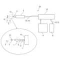
図1に示したように、本実施形態に係る液体噴射装置25は、液体3を噴射する液体噴射ノズル11を有する噴射部2と、噴射する液体3を貯留する液体タンク6と、加圧液体供給部であるポンプユニット27と、液体タンク6とポンプユニット27とをつなぐ液体3の流路10を成す液体吸引チューブ12と、ポンプユニット27と噴射部2とをつなぐ同じく流路10を成す送液チューブ14とを備える。
ポンプユニット27は、制御部4によって、送液チューブ14を通って噴射部2に送液される液体3の圧力等のポンプ動作が制御される。
As shown in FIG. 1, a
The
<液体噴射ノズル>
液体噴射ノズル11は、1つ又は複数個の噴射ノズル孔1を有し、噴射ノズル孔1から高圧の液体3が噴射されるものである。図1中の部分拡大図において、符号Fは液体噴射方向を示す。
噴射ノズル孔1から噴射された高圧の液体3は、噴射直後は連続流5であるが、液体3の表面張力によって直ぐに液滴化して液滴7の群に分裂する。液滴7の前記群は、液体噴射方向Fに一直線に並んで飛翔する。その飛翔する液滴7の群を対象物9に次々に当てることで所定の処理が実行される。
尚、図1中の部分拡大図は、図面を解り易くするために、液滴7及び連続流5の寸法が他の部材に対して大きく拡大され、実際の相対的な寸法関係は無視されている。
<Liquid injection nozzle>
The
The
In the partially enlarged view of FIG. 1, the dimensions of the
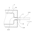
図2に示したように、液体噴射ノズル11は、噴射ノズル孔1と、噴射ノズル孔1より径が大きくて噴射ノズル孔1に接続する液体流路29とを有し、噴射ノズル孔1から噴射された連続流5が液滴化して生じる液滴7を対象物9に当てる。噴射ノズル孔1は円筒形状である。更に噴射ノズル孔1の液体流路29に接続する入り口の縁であるエッジ31の曲率半径Rは、噴射ノズル孔1のノズル孔径dの25%以下に構成されている。
即ち、エッジ31の曲率半径Rは、噴射ノズル孔1のノズル孔径dと関係付けられて設定されており、R/dが25%以下になる範囲で設定されている。
図2において、符号20は噴射ノズル孔1の孔壁面を示し、符号22は噴射口を示す。孔壁面20は直径がdの円筒形状であり、噴射口22は直径がdの円形である。
2, the
That is, the radius of curvature R of the
2,
<縮流>
図2は、液体3が噴射ノズル孔1から縮流18となって噴射された状態を表している。縮流18とは、図2に表したように、噴射ノズル孔1から噴射される連続流5が孔壁面20との間に隙間を有する状態で、即ち孔壁面20に接触しない状態で噴射される状態のことである。言い換えると、縮流18はノズル孔径dよりも小さい直径の連続流5になって噴射される状態のことである。その結果、縮流状態の噴射速度Vは縮流でない状態で噴射される連続流より速くなることが解っている。
<Constriction>
Fig. 2 shows a state in which the
本実施形態では、液体流路29も円筒形状に形成されている。尚、液体流路29は、円筒形状に限定されず、多角筒形状でもよい。
また、本実施形態では、噴射ノズル孔1の吐出側の端面13から所定の距離までの間において、液滴7の中心15の飛翔軌跡が、噴射ノズル孔1の中心軸17から半径rが0.5mm以内の範囲に収まるように構成されている。
In this embodiment, the
In addition, in this embodiment, the flight trajectory of the
<ノズル孔径と液滴のサイズ>
本実施形態では、噴射ノズル孔1のノズル孔径dは0.01mm~0.15mmの範囲で作られる。
液滴7のサイズは、非粘性の線形理論からノズル孔径dの約1.88倍になることが知られている。噴射ノズル孔1のノズル孔径dは0.01mm~0.15mmであるので、それを計算すると液滴のサイズは0.0188mm~0.282mmとなる。更に、噴射ノズル孔1の平滑さ等によって液滴サイズは多少ばらつくことを考慮すると、液滴のサイズは、平均液滴径としては約0.02mm~0.29mmとなる。
ここで、複数の液滴7は、実際には完全な球形ではなく楕円形等に変形しているものがほとんどであるので、「平均液滴径」は、最も長い径部分と最も短い径部分に基づく平均値として求めることになる。
<Nozzle hole diameter and droplet size>
In this embodiment, the nozzle hole diameter d of the
It is known that the size of the
Here, since most of the
<噴射圧力>
また、本実施形態に係る液体噴射装置25では、加圧液体供給部であるポンプユニット27は、噴射ノズル孔1から噴射される液体3の噴射圧力が0.2MPa~10MPaとなる供給圧力で液体3を供給するように構成される。
制御部4は、噴射ノズル孔1から噴射される液体3の噴射速度Vが所定の速度になるように噴射圧力を設定する。噴射速度Vが決まると飛翔する液滴7の速さも決まる。液滴7の速さは、噴射速度Vと空気抵抗の影響が表れるまで同じであり、速度Vで飛翔する。
<Injection pressure>
Furthermore, in the
The
<エッジの曲率半径Rはノズル孔径dの25%以下の説明>
(1)噴射速度Vの「解析値/理論値」から
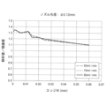
図3は、ノズル孔径dが0.12mmの場合の噴射速度Vの解析値/理論値と噴射ノズル孔1のエッジ31の曲率半径Rとの関係を示すグラフである。
ここで、噴射速度V(m/s)の「解析値」は、汎用の3次元熱流体解析ソフトウェア(FLOW-3D)を用いて、液体3の各設定流量(ml/min)50、70、90について求めた値である。また、「理論値」は、各ノズル孔径dにおいて、液体3の各設定流量(ml/min)50、70、90を、各噴射ノズル孔1のノズル断面積で除すことで決定される理論速度(m/s)である。
表1の左部分は、ノズル孔径が0.12mmの噴射ノズル孔1に対して、液体3の設定流量(ml/min)を50、70、90とした場合の対応する各理論速度(m/s)、即ち前記「理論値」が74、103、133であることを示している。
<Explanation of the edge curvature radius R being 25% or less of the nozzle hole diameter d>
(1) From the “Analytical Value/Theoretical Value” of the Ejection Velocity V FIG. 3 is a graph showing the relationship between the analytical value/theoretical value of the ejection velocity V and the radius of curvature R of the
Here, the "analytical value" of the ejection velocity V (m/s) is a value obtained for each set flow rate (ml/min) of 50, 70, and 90 of the liquid 3 using general-purpose three-dimensional thermal fluid analysis software (FLOW-3D). Also, the "theoretical value" is a theoretical velocity (m/s) determined by dividing each set flow rate (ml/min) of 50, 70, and 90 of the
The left part of Table 1 shows that for an
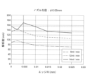
図4は、ノズル孔径が0.08mmの場合の噴射速度Vの解析値/理論値と噴射ノズル孔1のエッジ31の曲率半径Rとの関係を示すグラフである。
「解析値」は、前記3次元熱流体解析ソフトウェアを用いて、液体3の設定流量(ml/min)20、30、40について求めた値である。
表1の中央部分は、ノズル孔径が0.08mmの噴射ノズル孔1に対して、液体3の設定流量(ml/min)を20、30、40とした場合の対応する各理論速度(m/s)、即ち前記「理論値」が66、99、133であることを示している。
FIG. 4 is a graph showing the relationship between the analytical/theoretical value of the injection velocity V and the radius of curvature R of the
The "analysis values" are values obtained for set flow rates (ml/min) of 20, 30, and 40 for the liquid 3 using the three-dimensional thermal fluid analysis software.
The central part of Table 1 shows that when the set flow rate (ml/min) of the
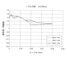
図5は、ノズル孔径が0.05mmの場合の噴射速度Vの解析値/理論値と噴射ノズル孔1のエッジ31の曲率半径Rとの関係を示すグラフである。
「解析値」は、前記3次元熱流体解析ソフトウェアを用いて、液体3の設定流量(ml/min)8、12、14について求めた値である。
表1の右部分は、ノズル孔径が0.05mmの噴射ノズル孔1に対して、液体3の設定流量(ml/min)を8、12、14とした場合の対応する各理論速度(m/s)、即ち前記「理論値」が68、102、119であることを示している。
FIG. 5 is a graph showing the relationship between the analytical/theoretical value of the injection velocity V and the radius of curvature R of the
The "analysis values" are values obtained for the set flow rates (ml/min) 8, 12, and 14 of the liquid 3 using the three-dimensional thermal fluid analysis software.
The right part of Table 1 shows that for a

図3において、噴射速度Vの「解析値」の「理論値」に対する比である「解析値/理論値」が少なくとも1.1を超えていれば、噴射速度Vが理論速度より1.1倍、即ち10%速くなっていることになる。この状態は縮流が形成されていると見ることができる。
図3において、ノズル孔径dが0.12mmでは、エッジ31の曲率半径Rが0.06mmで1.1を超えている。この場合のR/dは0.06/0.12×100=50%である。ノズル孔径dが0.12mmでは、曲率半径RをR/dが25%になるまで小さくしなくても縮流が形成されることになる。ノズル孔径dが0.12mmでは、その分、縮流を形成するための曲率半径Rの許容範囲が広いと言うことができる。
In Fig. 3, if the ratio of the "analytical value" of the injection velocity V to the "theoretical value", that is, "analytical value/theoretical value", exceeds at least 1.1, the injection velocity V is 1.1 times, i.e., 10% faster than the theoretical velocity. This state can be regarded as the formation of a contraction flow.
In Fig. 3, when the nozzle hole diameter d is 0.12 mm, the radius of curvature R of the
図4において、ノズル孔径dが0.08mmでは、エッジ31の曲率半径Rが0.04mmで1.1を超えている。この場合のR/dは0.04/0.08×100=50%である。ノズル孔径dが0.08mmでも、曲率半径RをR/dが25%になるまで小さくしなくても縮流が形成されることになる。ノズル孔径dが0.08mmでも、縮流を形成するための曲率半径Rの許容範囲が広いと言うことができる。
In Figure 4, when the nozzle hole diameter d is 0.08 mm, the radius of curvature R of the
図5において、ノズル孔径dが0.05mmでは、エッジ31の曲率半径Rが0.0125mmで1.1を超えている。この場合のR/dは0.0125/0.05×100=25%である。ノズル径が0.05mmでは、R/dが25%であるので縮流が形成されることになる。
In Figure 5, when the nozzle hole diameter d is 0.05 mm, the radius of curvature R of the
以上から、噴射ノズル孔1は、そのノズル孔径dが0.12mm、0.08mm、0.05mmのものについては、R/dが25%以下になるように作れば縮流が形成されることになることが解る。更に、ノズル孔径dが0.12mm、0.08mmのものは、R/dが50%でも縮流が形成されることになることが解る。
また、噴射ノズル孔1のノズル孔径dが0.15mmのもの、及び0.01mmのものについて、同様のデータを取得して同様の検討を行った。その結果、いずれもR/dが25%以下になるように作れば縮流が形成されることを確認した。
From the above, it can be seen that for the
In addition, similar data was obtained and a similar study was performed for the nozzle hole diameters d of the
表2は、噴射速度Vの「実測値」と前記「理論値」との比である理論速度比を、ノズル孔径dが0.12mm、0.08mm、0.05mmについて、表2中の各流量(ml/min)に対して求めたものである。ノズル孔径dが0.12mmのR/dは1.7%、0.08mmのR/dは1.3%、0.05mmのR/dは2.0%のものである。
噴射速度Vの実測値は、以下のようにして得た。
<噴射速度Vの実測値>
図12は、噴射ノズル孔1から噴射され、速度Vで飛翔する液滴7の飛翔軌跡を、高速度カメラを用いて撮影して得た高速撮影画像であり、その2~3枚(図中では3枚)の画像を選択し、着目した液滴7の移動距離Sを算出し、これを撮影時間間隔で除して液滴の速さを求め、それを噴射速度Vの実測値とした。
Table 2 shows the theoretical velocity ratio, which is the ratio of the "actual value" of the injection velocity V to the "theoretical value" mentioned above, for nozzle hole diameters d of 0.12 mm, 0.08 mm, and 0.05 mm, determined for each flow rate (ml/min) in Table 2. When the nozzle hole diameter d is 0.12 mm, R/d is 1.7%, when it is 0.08 mm, R/d is 1.3%, and when it is 0.05 mm, R/d is 2.0%.
The actual measurement of the ejection velocity V was obtained as follows.
<Measured value of ejection velocity V>
FIG. 12 shows high-speed images taken with a high-speed camera of the flight trajectory of a
具体的には、図3~図5から凡そのRの値を決定し、それから求めたR/dの値を実測値とした。
ノズル孔径dが0.12mmの場合、理論速度比が1.40、1.35、1.28なので、平均値は約1.34になる。図3からこの時のRの値は約0.002mmであるので、R/d=0.002/0.12=0.0166…≒1.7%となる。
ノズル孔径dが0.08mmの場合、理論速度比が1.44、1.42、1.35なので、平均値は約1.41になる。図4ではいずれも1.41に届いていないため、解析値/理論値が最大となるRの値を採用し、そのRの値は約0.001mmであるので、R/d=0.001/0.08=0.0125…≒1.3%となる。
ノズル孔径dが0.05mmの場合、理論速度比が1.36、1.35、1.31なので、平均値は約1.34になる。図5からこの時のRの値は約0.001mmまたは約0.004mmであるので、上記との整合性を考慮して0.001mmを採用した。よって、R/d=0.001/0.05=0.02≒2.0%となる。
Specifically, the approximate value of R was determined from FIGS. 3 to 5, and the value of R/d obtained from this was used as the actual measurement value.
When the nozzle hole diameter d is 0.12 mm, the theoretical velocity ratios are 1.40, 1.35, and 1.28, so the average value is approximately 1.34. From Figure 3, the value of R at this time is approximately 0.002 mm, so R/d = 0.002/0.12 = 0.0166... ≒ 1.7%.
When the nozzle hole diameter d is 0.08 mm, the theoretical velocity ratios are 1.44, 1.42, and 1.35, so the average value is approximately 1.41. In Figure 4, none of the values reach 1.41, so the value of R where the analytical value/theoretical value is maximum is adopted, and since the value of R is approximately 0.001 mm, R/d = 0.001/0.08 = 0.0125... ≒ 1.3%.
When the nozzle hole diameter d is 0.05 mm, the theoretical velocity ratios are 1.36, 1.35, and 1.31, so the average value is about 1.34. From Figure 5, the value of R at this time is about 0.001 mm or about 0.004 mm, so 0.001 mm was adopted in consideration of consistency with the above. Therefore, R/d = 0.001/0.05 = 0.02 ≒ 2.0%.
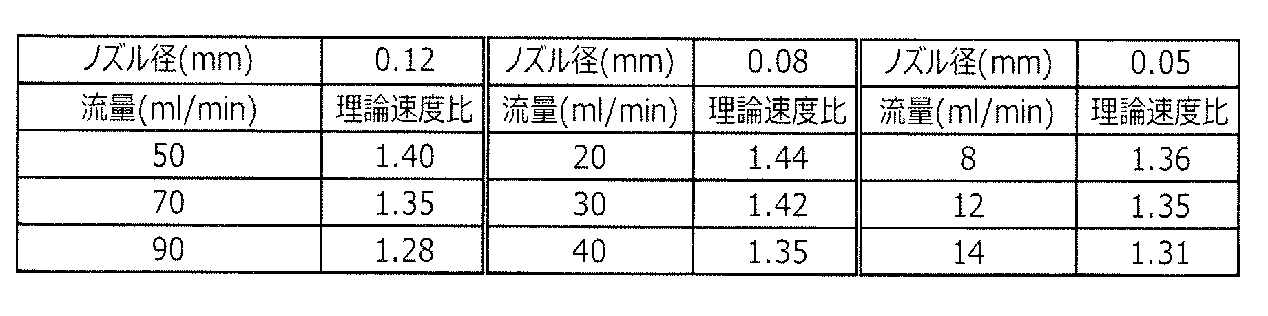
表2において、噴射速度Vの実測値と理論値の比である理論速度比の最小値は、ノズル孔径dによって異なるが、dが0.12mmでは1.28、dが0.08mmでは1.35、dが0.05mmでは1.31である。
よって、測定した各噴射ノズル孔1では実測の噴射速度Vが理論速度より全て速くなっていることが解る。即ち縮流が形成されていることになる。
更に、噴射ノズル孔1のノズル孔径dが0.15mmのもの、及び0.01mmのものについて、同様に実測値と理論値のデータを取得して同様の検討を行った。その結果、いずれもR/dが25%以下になるように作れば縮流が形成されることを確認した。
In Table 2, the minimum theoretical velocity ratio, which is the ratio of the actual value of the injection velocity V to the theoretical value, varies depending on the nozzle hole diameter d, but is 1.28 when d is 0.12 mm, 1.35 when d is 0.08 mm, and 1.31 when d is 0.05 mm.
Therefore, it is understood that the actually measured injection velocity V is faster than the theoretical velocity in all the injection nozzle holes 1. In other words, a contraction flow is formed.
Furthermore, similar studies were carried out on the nozzle hole diameters d of the
<実施形態1の効果の説明>
本実施形態によれば、噴射ノズル孔1の液体流路29に接続する入り口のエッジ31の曲率半径Rは、噴射ノズル孔1のノズル孔径dの25%以下、即ちR/dは25%以下である。これにより、噴射ノズル孔1の噴射口22から噴射された液体3の連続流5が分裂してできる液滴7を直進性良く飛翔させることができると共に、液体3を縮流18として噴射させることが可能になる。
縮流18にすることで、縮流でない場合よりも噴射速度Vが高まるので、その高まった分だけ液滴7の衝撃圧を高めることができる。
<Description of Effects of First Embodiment>
According to this embodiment, the radius of curvature R of the
By forming the contraction flow 18, the ejection velocity V becomes higher than in the case where the ejection velocity is not contraction, and the impact pressure of the
また、縮流18の形成し易さは、噴射ノズル孔1のエッジ31の曲率半径Rがゼロ、即ち真に90度である方がよいとされている。しかし、エッジ31の曲率半径Rがゼロの噴射ノズル孔1を作ることは困難であり、曲率半径Rが極力ゼロに近いものを目指して作ることになる。
本発明者らは、エッジ31の曲率半径Rがゼロでなくても縮流18を形成することが可能である範囲があることを確認した。即ち、エッジ31の曲率半径Rがゼロでなくても、ある範囲まで縮流18を形成できることを確認した。更にその確認の際に、ノズル孔径dが大きくなるほど縮流18を形成できる範囲が広くなることを発見した。本実施形態において、「エッジ31の曲率半径Rは、噴射ノズル孔1dノズル孔径dの25%以下」は、前記発見に基づくものである。
これにより本実施形態によれば、縮流18を形成できる噴射ノズル孔1を製造するに際して、漠然とエッジ31の曲率半径Rをゼロにすることを目指すといった意識をしなくてもよくなり、即ち、噴射ノズル孔1のノズル孔径dに応じて現実的に必要な曲率半径Rの大きさを把握することができ、それにより製造が容易になる。
It is said that the ease of forming the contracted flow 18 is better when the radius of curvature R of the
The inventors have confirmed that there is a range in which the contracted flow 18 can be formed even if the radius of curvature R of the
As a result, according to this embodiment, when manufacturing the
[実施形態2]
次に、本発明の実施形態2に係る液体噴射ノズル1について、図6から図11に基づいて説明する。図6~図8において、複数の破線が、各流量における基準値を示す。
本実施形態では、エッジ31の曲率半径Rのノズル孔径dに対する割合R/dが5%~10%の範囲にあるように構成される。
[Embodiment 2]
Next, a
In this embodiment, the ratio R/d of the radius of curvature R of the
<エッジの曲率半径Rはノズル孔径dの5%~10%の範囲の説明>
(1)噴射速度Vの「解析値/基準値」から
図6は、ノズル孔径dが0.12mmの場合の、噴射ノズル孔1のエッジ31の曲率半径Rに対する噴射速度Vの解析値と基準値を比較したグラフである。液体3の設定流量(ml/min)を50、70、90とした場合である。
ここで、噴射速度V(m/s)の「解析値」は、上記と同じである。「基準値」は、エッジ31の曲率半径R=0、すなわち、エッジ31が直角になるときの噴射速度の解析値を求めて、それを基準値とした。エッジ31が直角となる状態は、縮流18の形成において有利な状態と言えるので、それを基準値とした。曲率半径Rを直角としたときの噴射速度の解析値である「基準値」は、以下のように求めた。
<基準値の求め方>
図2に示したエッジ31を直角にして作成した解析モデルを用いて、前記3次元熱流体解析ソフトウェアにより、各設定流量(ml/min)における噴射速度を求めた。
<Explanation that the edge curvature radius R is in the range of 5% to 10% of the nozzle hole diameter d>
6 is a graph comparing the analytical value and the reference value of the ejection velocity V with respect to the radius of curvature R of the
Here, the "analytical value" of the ejection velocity V (m/s) is the same as above. For the "reference value", the analytical value of the ejection velocity when the radius of curvature R of the
<How to calculate the standard value>
Using an analytical model created by making the
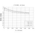
図7は、ノズル孔径dが0.08mmの場合の噴射速度Vの解析値/基準値と噴射ノズル孔1のエッジ31の曲率半径Rとの関係を示すグラフである。液体3の設定流量(ml/min)を20、30、40とした場合である。
図8は、ノズル孔径dが0.05mmの場合の噴射速度Vの解析値/基準値と噴射ノズル孔1のエッジ31の曲率半径Rとの関係を示すグラフである。液体3の設定流量(ml/min)を8、12、14とした場合である。
7 is a graph showing the relationship between the analytical value/reference value of the ejection velocity V and the curvature radius R of the
8 is a graph showing the relationship between the analytical value/reference value of the ejection velocity V and the curvature radius R of the
図6において、ノズル孔径dが0.12mmでは、エッジ31の曲率半径Rが0.012mmで基準値を上回る。この場合のR/dは、0.012/0.12×100=10%である。
図7において、ノズル孔径dが0.08mmでは、エッジ31の曲率半径Rが0.008mmで基準値を上回る。この場合のR/dは、0.008/0.08×100=10%である。
図8において、ノズル孔径dが0.05mmでは、エッジ31の曲率半径Rが0.005mmで基準値を上回る。この場合のR/dは、0.005/0.05×100=10%である。
6, when the nozzle hole diameter d is 0.12 mm, the radius of curvature R of the
7, when the nozzle hole diameter d is 0.08 mm, the radius of curvature R of the
8, when the nozzle hole diameter d is 0.05 mm, the radius of curvature R of the
以上から、噴射ノズル孔1のノズル孔径dが0.12mm、0.08mm、0.05mmのものについては、R/dが10%以下になるように作ることで、縮流18が形成される確率が高まることが解る。 From the above, it can be seen that for injection nozzle holes 1 with nozzle hole diameters d of 0.12 mm, 0.08 mm, and 0.05 mm, the probability of a contraction flow 18 being formed is increased by making R/d 10% or less.
(2)噴射速度Vの「解析値/実測値」から
図9は、ノズル孔径dが0.12mmの場合の噴射速度Vの解析値/実測値と噴射ノズル孔1のエッジ31の曲率半径Rとの関係を示すグラフである。液体3の設定流量(ml/min)を50、70、90とした場合である。
ここで、噴射速度V(m/s)の「解析値」及び「実測値」は、上記と同じである。
9 is a graph showing the relationship between the analytical value/actual measurement value of the ejection velocity V and the curvature radius R of the
Here, the "analytical value" and "measured value" of the ejection velocity V (m/s) are the same as above.
図10は、ノズル孔径dが0.08mmの場合の噴射速度Vの解析値/実測値と噴射ノズル孔1のエッジ31の曲率半径Rとの関係を示すグラフである。液体3の設定流量(ml/min)を20、30、40とした場合である。
図11は、ノズル孔径dが0.05mmの場合の噴射速度Vの解析値/実測値と噴射ノズル孔1のエッジ31の曲率半径Rとの関係を示すグラフである。液体3の設定流量(ml/min)を8、12、14とした場合である。
10 is a graph showing the relationship between the analytical value/actual measurement value of the ejection velocity V and the curvature radius R of the
11 is a graph showing the relationship between the analytical value/actual measurement value of the ejection velocity V and the curvature radius R of the
図9において、ノズル孔径dが0.12mmでは、液体3の全ての流量(ml/min)において、エッジ31の曲率半径Rが0.006mmで1をほぼ上回る。この場合のR/dは0.006/0.12×100=5%である。
図10において、ノズル孔径dが0.08mmでは、液体3の全ての流量(ml/min)において、エッジ31の曲率半径Rが0.004mmで1をほぼ上回る。この場合のR/dは0.004/0.08×100=5%である。
図11において、ノズル孔径dが0.05mmでは、液体3の全ての流量(ml/min)において、エッジ31の曲率半径Rが0.0025mmで1をほぼ上回る。この場合のR/dは0.0025/0.05×100=5%である。
9, when the nozzle hole diameter d is 0.12 mm, the radius of curvature R of the
10, when the nozzle hole diameter d is 0.08 mm, the radius of curvature R of the
11, when the nozzle hole diameter d is 0.05 mm, the radius of curvature R of the
以上から、噴射ノズル孔1のノズル孔径dが0.12mm、0.08mm、0.05mmのものについては、R/dが5%になるように作ることで、縮流18が形成される確率が高まることが解る。
即ち、噴射ノズル孔1のエッジ31の曲率半径Rをノズル孔径dの5%にすれば、確実に縮流18を形成させることができると言える。また、噴射速度Vは、理論速度の約1.3倍まで増幅され、理論上より1.3倍強い衝撃圧を発生させることができることになり、高い破砕、洗浄効果が期待することができる。
言い換えれば、理論上より約30%少ない液体3の流量(ml/min)で、噴射速度Vにより決まる所望の衝撃圧を発生させることができることになり、噴射する液体3の低流量化が図れる。
From the above, it can be seen that for injection nozzle holes 1 with nozzle hole diameters d of 0.12 mm, 0.08 mm, and 0.05 mm, the probability of the contraction flow 18 being formed is increased by making R/
That is, if the radius of curvature R of the
In other words, the desired impact pressure determined by the ejection velocity V can be generated with a flow rate (ml/min) of the liquid 3 that is approximately 30% less than the theoretical value, thereby enabling the flow rate of the ejected liquid 3 to be reduced.
本実施形態によれば、エッジ31の曲率半径Rは、ノズル孔径dの5%~10%の範囲にある。R/dが5%以上であれば製造の困難性は問題になりにくい。また、R/dが10%以下であればノズル孔径dが広範囲に亘って縮流18を形成できる確率が25%の場合より高い。これにより、縮流18の形成の確実性の高い液体噴射ノズル11を製造容易に提供することができる。
In this embodiment, the radius of curvature R of the
〔他の実施形態〕
本発明の実施形態に係る液体噴射ノズル1及び液体噴射装置25は、以上述べたような構成を有することを基本とするものであるが、本願発明の要旨を逸脱しない範囲内での部分的構成の変更や省略等を行うことは勿論可能である。
Other Embodiments
The
1 噴射ノズル孔、2 噴射部、3 液体、4 制御部、5 連続流、
6 液体タンク、7 液滴、9 対象物、10 流路、11 液体噴射ノズル、
12 液体吸引チューブ、14 送液チューブ、15 中心、17 中心軸、
20 孔壁面、21 液体流入口、22 噴射口、25 液体噴射装置、
27 加圧液体供給部(ポンプユニット)、29 液体流路、31 エッジ
F 液体噴射方向、R 曲率半径、d ノズル孔径
1 Injection nozzle hole, 2 Injection part, 3 Liquid, 4 Control part, 5 Continuous flow,
6 liquid tank, 7 droplet, 9 object, 10 flow path, 11 liquid injection nozzle,
12 liquid suction tube, 14 liquid delivery tube, 15 center, 17 central axis,
20 hole wall surface, 21 liquid inlet, 22 injection port, 25 liquid injection device,
27 Pressurized liquid supply unit (pump unit), 29 Liquid flow path, 31 Edge F Liquid ejection direction, R Curvature radius, d Nozzle hole diameter
Claims (6)
前記噴射ノズル孔より径が大きくて前記噴射ノズル孔に接続する液体流路と、を有し、
前記噴射ノズル孔から噴射された連続流が液滴化して生じる液滴を対象物に当てる液体噴射ノズルであって、
前記噴射ノズル孔は円筒形状であり、
前記噴射ノズル孔の前記液体流路に接続する入り口のエッジの曲率半径は、前記噴射ノズル孔のノズル孔径の5%~10%の範囲にある、
ことを特徴とする液体噴射ノズル。 An injection nozzle hole;
a liquid flow path having a diameter larger than that of the ejection nozzle hole and connected to the ejection nozzle hole,
A liquid injection nozzle that converts a continuous flow injected from the injection nozzle hole into droplets and applies the droplets to an object,
The injection nozzle hole is cylindrical,
The radius of curvature of the edge of the inlet of the injection nozzle hole connected to the liquid flow path is in the range of 5% to 10% of the nozzle hole diameter of the injection nozzle hole.
A liquid injection nozzle.
前記ノズル孔径は0.01mm~0.15mmの範囲にある、
ことを特徴とする液体噴射ノズル。 The liquid injection nozzle according to claim 1 ,
The nozzle hole diameter is in the range of 0.01 mm to 0.15 mm.
A liquid injection nozzle.
前記噴射ノズル孔から噴射された連続流の直径は、前記ノズル孔径よりも小さい、The diameter of the continuous flow injected from the injection nozzle hole is smaller than the nozzle hole diameter.
ことを特徴とする液体噴射ノズル。A liquid injection nozzle.
前記液滴の平均液滴径は、前記ノズル孔径よりも大きい、The average droplet diameter of the droplets is larger than the nozzle hole diameter.
ことを特徴とする液体噴射ノズル。A liquid injection nozzle.
前記噴射ノズル孔から噴射された前記連続流の速度は、前記液体流路内を流通する液体の速度よりも速い、a velocity of the continuous flow injected from the injection nozzle hole is faster than a velocity of the liquid flowing through the liquid flow path;
ことを特徴とする液体噴射ノズル。A liquid injection nozzle.
前記液体噴射ノズルに液体を加圧して供給する加圧液体供給部を備え、
前記液体噴射ノズルは請求項1から5のいずれか1項に記載のものである、
ことを特徴とする液体噴射装置。
A liquid ejection device including a liquid ejection nozzle that ejects a continuous flow of liquid into droplets and ejects the droplets onto a target object,
a pressurized liquid supply unit that pressurizes and supplies liquid to the liquid ejection nozzle,
The liquid injection nozzle is as defined in any one of claims 1 to 5 .
A liquid ejection apparatus comprising:
Priority Applications (3)
| Application Number | Priority Date | Filing Date | Title |
|---|---|---|---|
| JP2021027342A JP7608863B2 (en) | 2021-02-24 | 2021-02-24 | Liquid injection nozzle and liquid injection device |
| CN202210159086.7A CN114950751B (en) | 2021-02-24 | 2022-02-21 | Liquid ejecting nozzle and liquid ejecting apparatus |
| US17/652,174 US20220266267A1 (en) | 2021-02-24 | 2022-02-23 | Liquid jet nozzle and liquid jet device |
Applications Claiming Priority (1)
| Application Number | Priority Date | Filing Date | Title |
|---|---|---|---|
| JP2021027342A JP7608863B2 (en) | 2021-02-24 | 2021-02-24 | Liquid injection nozzle and liquid injection device |
Publications (2)
| Publication Number | Publication Date |
|---|---|
| JP2022128884A JP2022128884A (en) | 2022-09-05 |
| JP7608863B2 true JP7608863B2 (en) | 2025-01-07 |
Family
ID=82900358
Family Applications (1)
| Application Number | Title | Priority Date | Filing Date |
|---|---|---|---|
| JP2021027342A Active JP7608863B2 (en) | 2021-02-24 | 2021-02-24 | Liquid injection nozzle and liquid injection device |
Country Status (3)
| Country | Link |
|---|---|
| US (1) | US20220266267A1 (en) |
| JP (1) | JP7608863B2 (en) |
| CN (1) | CN114950751B (en) |
Citations (5)
| Publication number | Priority date | Publication date | Assignee | Title |
|---|---|---|---|---|
| JP2005103984A (en) | 2003-09-30 | 2005-04-21 | Brother Ind Ltd | Nozzle plate manufacturing method and nozzle plate |
| JP2006124892A (en) | 2004-11-01 | 2006-05-18 | Ikeuchi:Kk | One-fluid nozzle for stick flow injection |
| JP2010129840A (en) | 2008-11-28 | 2010-06-10 | Asahi Sunac Corp | Cleaning nozzle |
| JP2015139833A (en) | 2014-01-27 | 2015-08-03 | 株式会社スギノマシン | Fluid nozzle |
| JP2021023998A (en) | 2019-07-31 | 2021-02-22 | セイコーエプソン株式会社 | Liquid jet device and liquid jet method |
Family Cites Families (9)
| Publication number | Priority date | Publication date | Assignee | Title |
|---|---|---|---|---|
| NL8001874A (en) * | 1980-03-29 | 1981-11-02 | Stamicarbon | DEVICE FOR SPRAYING A LIQUID USING A GAS. |
| JP2729395B2 (en) * | 1989-03-08 | 1998-03-18 | 旭サナック株式会社 | Nozzle tip for liquid pressurized spray |
| JP2001241887A (en) * | 2000-03-02 | 2001-09-07 | Babcock Hitachi Kk | Lance with nozzle for jet cleaning |
| JP4204555B2 (en) * | 2003-01-24 | 2009-01-07 | ターボテクト、リミテッド | Method and jet nozzle for scattering droplets in a gas stream |
| WO2009091416A2 (en) * | 2007-06-22 | 2009-07-23 | Arizona Board Of Regents, Acting For And On Behalf Of Arizona State University | Gas dynamic virtual nozzle for generation of microscopic droplet streams |
| GB201006080D0 (en) * | 2010-04-13 | 2010-05-26 | Univ Salford The | Aerosol spray device |
| EP3244705B1 (en) * | 2016-05-11 | 2019-07-03 | ETH Zürich | Method and light source for providing uv or x-ray light |
| JP6865952B2 (en) * | 2016-12-07 | 2021-04-28 | 旭サナック株式会社 | 1 fluid nozzle |
| JP6161842B1 (en) * | 2017-02-15 | 2017-07-12 | 株式会社渡辺製作所 | Droplet ejection device |
-
2021
- 2021-02-24 JP JP2021027342A patent/JP7608863B2/en active Active
-
2022
- 2022-02-21 CN CN202210159086.7A patent/CN114950751B/en active Active
- 2022-02-23 US US17/652,174 patent/US20220266267A1/en active Pending
Patent Citations (5)
| Publication number | Priority date | Publication date | Assignee | Title |
|---|---|---|---|---|
| JP2005103984A (en) | 2003-09-30 | 2005-04-21 | Brother Ind Ltd | Nozzle plate manufacturing method and nozzle plate |
| JP2006124892A (en) | 2004-11-01 | 2006-05-18 | Ikeuchi:Kk | One-fluid nozzle for stick flow injection |
| JP2010129840A (en) | 2008-11-28 | 2010-06-10 | Asahi Sunac Corp | Cleaning nozzle |
| JP2015139833A (en) | 2014-01-27 | 2015-08-03 | 株式会社スギノマシン | Fluid nozzle |
| JP2021023998A (en) | 2019-07-31 | 2021-02-22 | セイコーエプソン株式会社 | Liquid jet device and liquid jet method |
Also Published As
| Publication number | Publication date |
|---|---|
| US20220266267A1 (en) | 2022-08-25 |
| CN114950751B (en) | 2024-01-26 |
| CN114950751A (en) | 2022-08-30 |
| JP2022128884A (en) | 2022-09-05 |
Similar Documents
| Publication | Publication Date | Title |
|---|---|---|
| JP6258994B2 (en) | Usage of flat jet nozzle and flat jet nozzle | |
| JP2016501333A5 (en) | ||
| CN106456915A (en) | Aerosolisation engine for liquid drug delivery background | |
| EP3408032B1 (en) | Improved swirl nozzle assembly with high efficiency mechanical break up to generate mist sprays of uniform small droplets | |
| WO2012039343A1 (en) | Liquid atomizing device and liquid atomizing method | |
| CN114950750B (en) | Liquid ejecting nozzle and liquid ejecting apparatus | |
| JP2012223752A (en) | Liquid atomization device | |
| JP7608863B2 (en) | Liquid injection nozzle and liquid injection device | |
| JP5080789B2 (en) | Nozzle device and method for forming atomization mechanism thereof | |
| JP2011098284A (en) | Nozzle for mixing gas and liquid | |
| US20020030122A1 (en) | Method and apparatus for generating water sprays, and methods of cleaning using water sprays | |
| US4378088A (en) | Liquid atomizing method and apparatus | |
| JP5452448B2 (en) | Atomizing device | |
| JP2018089597A (en) | One fluid nozzle | |
| JP7282389B2 (en) | mist nozzle | |
| JP2004050122A (en) | Nozzle | |
| JP2023064254A (en) | Aperture area determination method and droplet jetting device | |
| US20220266266A1 (en) | Liquid jet device for skin cleaning | |
| JP7729112B2 (en) | liquid injection device | |
| JP2003093926A (en) | Fluid injection nozzle | |
| JP2013103175A (en) | Liquid atomization apparatus | |
| JP2023022555A (en) | Injection nozzle and liquid injection device | |
| EP0085583A2 (en) | Liquid atomizing method and apparatus | |
| JP2025042772A (en) | Liquid injection device | |
| JP2012254457A (en) | Liquid atomizing device and liquid atomizing method |
Legal Events
| Date | Code | Title | Description |
|---|---|---|---|
| A621 | Written request for application examination |
Free format text: JAPANESE INTERMEDIATE CODE: A621 Effective date: 20231117 |
|
| A977 | Report on retrieval |
Free format text: JAPANESE INTERMEDIATE CODE: A971007 Effective date: 20240724 |
|
| A131 | Notification of reasons for refusal |
Free format text: JAPANESE INTERMEDIATE CODE: A131 Effective date: 20240730 |
|
| A521 | Request for written amendment filed |
Free format text: JAPANESE INTERMEDIATE CODE: A523 Effective date: 20240829 |
|
| TRDD | Decision of grant or rejection written | ||
| A01 | Written decision to grant a patent or to grant a registration (utility model) |
Free format text: JAPANESE INTERMEDIATE CODE: A01 Effective date: 20241119 |
|
| A61 | First payment of annual fees (during grant procedure) |
Free format text: JAPANESE INTERMEDIATE CODE: A61 Effective date: 20241202 |
|
| R150 | Certificate of patent or registration of utility model |
Ref document number: 7608863 Country of ref document: JP Free format text: JAPANESE INTERMEDIATE CODE: R150 |