JP7608859B2 - Automatic transaction device and program - Google Patents
Automatic transaction device and program Download PDFInfo
- Publication number
- JP7608859B2 JP7608859B2 JP2021023435A JP2021023435A JP7608859B2 JP 7608859 B2 JP7608859 B2 JP 7608859B2 JP 2021023435 A JP2021023435 A JP 2021023435A JP 2021023435 A JP2021023435 A JP 2021023435A JP 7608859 B2 JP7608859 B2 JP 7608859B2
- Authority
- JP
- Japan
- Prior art keywords
- door
- unit
- user
- fingers
- operation unit
- Prior art date
- Legal status (The legal status is an assumption and is not a legal conclusion. Google has not performed a legal analysis and makes no representation as to the accuracy of the status listed.)
- Active
Links
- 230000007246 mechanism Effects 0.000 claims description 60
- 238000012545 processing Methods 0.000 description 39
- 230000006870 function Effects 0.000 description 14
- 238000010586 diagram Methods 0.000 description 10
- 238000003780 insertion Methods 0.000 description 10
- 230000037431 insertion Effects 0.000 description 10
- 230000007723 transport mechanism Effects 0.000 description 8
- 238000000034 method Methods 0.000 description 6
- 238000010200 validation analysis Methods 0.000 description 6
- 230000032258 transport Effects 0.000 description 4
- 230000009471 action Effects 0.000 description 3
- 230000000694 effects Effects 0.000 description 3
- 238000004590 computer program Methods 0.000 description 2
- 238000012423 maintenance Methods 0.000 description 2
- 238000012986 modification Methods 0.000 description 2
- 230000004048 modification Effects 0.000 description 2
- 230000008859 change Effects 0.000 description 1
- 238000004891 communication Methods 0.000 description 1
- 238000000151 deposition Methods 0.000 description 1
- 239000002184 metal Substances 0.000 description 1
- 238000011017 operating method Methods 0.000 description 1
- 238000003825 pressing Methods 0.000 description 1
- 230000008569 process Effects 0.000 description 1
- 238000012797 qualification Methods 0.000 description 1
- 210000003462 vein Anatomy 0.000 description 1
Images


Landscapes
- Lock And Its Accessories (AREA)
Description
本発明は、装置およびプログラムに関する。 The present invention relates to an apparatus and a program.
従来、筐体、および筐体の扉をロックするロック機構を備える多様な装置が存在する。このような装置の一例として、現金の入金取引および出金取引などを行う自動取引装置が挙げられる。係員は、自動取引装置のロックを解除することで、筐体の扉を開き、内部ユニットにアクセスすることができる。なお、ロック機構は、内部ユニットに対して設けられてもよい。 Conventionally, there are various devices that include a housing and a locking mechanism for locking the door of the housing. One example of such a device is an automated teller machine that performs cash deposit and withdrawal transactions. By unlocking the automated teller machine, an attendant can open the door of the housing and access the internal unit. The locking mechanism may be provided for the internal unit.
上記のロック機構に関し、特許文献1には、電磁ロック機構を有する自動取引装置であって、タッチパネルに操作ボタンを表示し、当該操作ボタンへの操作に基づいて電磁ロックを解除する自動取引装置が開示されている。
Regarding the above locking mechanism,
しかし、係員が一方の手で扉を開ける方向または内部ユニットを引き出す方向に力をかけながら、他方の手でタッチパネルを操作して電磁ロックの解除を行おうとすると、扉(または内部ユニット)にかかる力が摩擦力(抵抗力)となり電磁ロックが解除されない場合があった。 However, when an attendant applies force with one hand in the direction to open the door or pull out the internal unit, while trying to release the electromagnetic lock by operating the touch panel with the other hand, the force applied to the door (or internal unit) creates friction (resistance), which sometimes prevents the electromagnetic lock from being released.
そこで、本発明は、上記問題に鑑みてなされたものであり、本発明の目的とするところは、円滑なロック解除を実現することが可能な、新規かつ改良された装置およびプログラムを提供することにある。 The present invention has been made in consideration of the above problems, and the object of the present invention is to provide a new and improved device and program that can achieve smooth unlocking.
上記課題を解決するために、本発明のある観点によれば、内部に現金を収納する収納庫を備える筐体と、前記収納庫へのアクセスを規制する、前記筐体に設けられた扉と、前記扉が閉じられた状態で前記扉をロックし、前記扉のロックの実施および解除が電磁的に制御されるロック機構と、第1のオブジェクトおよび第2のオブジェクトを表示するものであって、前記第1のオブジェクトの表示位置と前記第2のオブジェクトの表示位置との距離は、ユーザの片手の手指では前記第1のオブジェクトに触れつつ前記第2のオブジェクトに触れることができず、前記ユーザが両手の手指のそれぞれで前記第1のオブジェクトに触れつつ前記第2のオブジェクトに触れることが必要となる距離である、表示部と、前記扉に設けられるものであって、前記ロック機構による前記扉のロックが電磁的に解除された状態で前記ユーザが把持して前記扉を開閉可能であり、また前記ユーザが両手の手指のそれぞれで前記第1のオブジェクトに触れつつ前記第2のオブジェクトに触れるときには把持できない位置に設けられる把持部と、前記ユーザの手指により、前記第1のオブジェクトへ第1の接触操作が行われ、同時に前記第2のオブジェクトへ第2の接触操作が行われていることに基づき、前記ロック機構に前記扉のロックを解除させる制御部と、を備える、自動取引装置が提供される。
In order to solve the above problem, according to one aspect of the present invention, there is provided a cash register comprising: a housing having a storage unit for storing cash therein ; a door provided in the housing for restricting access to the storage unit ; a locking mechanism for locking the door when the door is closed , and for electromagnetically controlling the locking and unlocking of the door ; and a display device for displaying a first object and a second object, wherein a distance between a display position of the first object and a display position of the second object is such that a user cannot touch the first object and touch the second object with the fingers of one hand, and the user cannot touch the first object and touch the second object with the fingers of both hands. a display unit that is disposed on the door and that can be grasped by the user to open and close the door when the door is electromagnetically unlocked by the locking mechanism, and that is disposed at a position that cannot be grasped when the user is touching the first object and the second object with each of the fingers of both hands at the same time; and a control unit that causes the locking mechanism to unlock the door based on a first contact operation being performed on the first object and a second contact operation being performed on the second object by the user's fingers.
また、上記課題を解決するために、本発明の別の観点によれば、自動取引装置であって、内部に現金を収納する収納庫を備える筐体と、前記収納庫へのアクセスを規制する、前記筐体に設けられた扉と、前記扉が閉じられた状態で前記扉をロックし、前記扉のロックの実施および解除が電磁的に制御されるロック機構と、生体認証センサ、数値入力用キー、ハンドセット、タッチパネルまたは前記自動取引装置を操作するための物理ボタンのいずれかである第1の操作部と、生体認証センサ、数値入力用キー、ハンドセット、タッチパネルまたは前記自動取引装置を操作するための物理ボタンのいずれかであり、かつ、前記第1の操作部と異なる種類の操作部である第2の操作部と、前記扉に設けられるものであって、前記ロック機構による前記扉のロックが電磁的に解除された状態でユーザが把持して前記扉を開閉可能であり、また前記ユーザが両手の手指のそれぞれで前記第1の操作部に触れつつ前記第2の操作部に触れるときには把持できない位置に設けられる把持部と、前記ユーザの手指により、前記第1の操作部へ第1の接触操作が行われ、同時に前記第2の操作部へ第2の接触操作が行われていることに基づき、前記ロック機構に前記扉のロックを解除させる制御部と、を備え、前記第1の操作部と前記第2の操作部との距離は、前記ユーザの片手の手指では前記第1の操作部に触れつつ前記第2の操作部に触れることができず、前記ユーザが両手の手指のそれぞれで前記第1の操作部に触れつつ前記第2の操作部に触れることが必要となる距離である、自動取引装置が提供される。
In order to solve the above-mentioned problems, according to another aspect of the present invention, an automated transaction device includes a housing having a storage unit for storing cash therein, a door provided in the housing for restricting access to the storage unit , a locking mechanism that locks the door when the door is closed and electromagnetically controls the locking and unlocking of the door, a first operation unit which is any one of a biometric authentication sensor, a numeric input key, a handset, a touch panel, or a physical button for operating the automated transaction device, a second operation unit which is any one of a biometric authentication sensor, a numeric input key, a handset, a touch panel, or a physical button for operating the automated transaction device and is a different type of operation unit from the first operation unit, and a locking mechanism that is provided on the door and locks the door by the locking mechanism. an automatic transaction device including a gripping portion that can be gripped by a user to open and close the door with the lock on the door electromagnetically released, the gripping portion being provided in a position where the user cannot grip the door when touching the first operation portion and the second operation portion with each of the fingers of both hands; and a control portion that causes the locking mechanism to unlock the door based on a first contact operation being performed by the user's fingers on the first operation portion and simultaneously a second contact operation being performed on the second operation portion, wherein a distance between the first operation portion and the second operation portion is such that the fingers of the user's one hand cannot touch the first operation portion and the second operation portion at the same time, but the user is required to touch the first operation portion and the second operation portion with each of the fingers of both hands.
また、上記課題を解決するために、本発明の別の観点によれば、内部に現金を収納する収納庫を備える筐体、前記収納庫へのアクセスを規制する、前記筐体に設けられた扉、前記扉が閉じられた状態で前記扉をロックし、前記扉のロックの実施および解除が電磁的に制御されるロック機構、第1のオブジェクトおよび第2のオブジェクトを表示するものであって、前記第1のオブジェクトの表示位置と前記第2のオブジェクトの表示位置との距離は、ユーザの片手の手指では前記第1のオブジェクトに触れつつ前記第2のオブジェクトに触れることができず、前記ユーザが両手の手指のそれぞれで前記第1のオブジェクトに触れつつ前記第2のオブジェクトに触れることが必要となる距離である表示部、および、前記扉に設けられるものであって、前記ロック機構による前記扉のロックが電磁的に解除された状態で前記ユーザが把持して前記扉を開閉可能となり、前記ユーザが両手の手指のそれぞれで前記第1のオブジェクトに触れつつ前記第2のオブジェクトに触れるときには把持できない位置に設けられる把持部を有する自動取引装置を、前記ユーザの手指により、前記第1のオブジェクトへ第1の接触操作が行われ、同時に前記第2のオブジェクトへ第2の接触操作が行われていることに基づき、前記ロック機構に前記扉のロックを解除させる制御部と、として機能させるための、プログラムが提供される。
Further, in order to solve the above-mentioned problem, according to another aspect of the present invention, there is provided a housing having a storage unit for storing cash therein, a door provided in the housing for restricting access to the storage unit , a locking mechanism for locking the door when the door is closed and for electromagnetically controlling locking and unlocking of the door, and a display device for displaying a first object and a second object, wherein a distance between a display position of the first object and a display position of the second object is such that a user cannot touch the first object and the second object at the same time with the fingers of one hand, and the user cannot touch the first object and the second object at the same time with the fingers of both hands. a display unit that is at a distance that requires the user to touch the display unit when the door is opened, and a grip unit that is provided on the door and can be grasped by the user to open and close the door when the door is electromagnetically unlocked by the locking mechanism, and that is provided at a position that the user cannot grip when the user is touching the second object while touching the first object with each of the fingers of both hands , and a control unit that causes the locking mechanism to unlock the door based on a first contact operation being performed on the first object by the user's fingers and simultaneously a second contact operation being performed on the second object .
以上説明した本発明によれば、円滑なロック解除を実現することが可能である。 According to the present invention described above, it is possible to achieve smooth unlocking.
以下に添付図面を参照しながら、本発明の実施の形態について詳細に説明する。なお、本明細書及び図面において、実質的に同一の機能構成を有する構成要素については、同一の符号を付することにより重複説明を省略する。 The following describes in detail an embodiment of the present invention with reference to the accompanying drawings. Note that in this specification and the drawings, components having substantially the same functional configuration are designated by the same reference numerals to avoid redundant description.
また、本明細書及び図面において、実質的に同一の機能構成を有する複数の構成要素を、同一の符号の後に異なるアルファベットを付して区別する場合もある。ただし、実質的に同一の機能構成を有する複数の構成要素の各々を特に区別する必要がない場合、複数の構成要素の各々に同一符号のみを付する。 In addition, in this specification and drawings, multiple components having substantially the same functional configuration may be distinguished by adding different letters after the same reference numeral. However, if there is no particular need to distinguish between multiple components having substantially the same functional configuration, each of the multiple components will be given only the same reference numeral.
<自動取引装置の構成>
本発明の一実施形態は、筐体、扉およびロック機構を備える装置に関する。以下では、このような装置の一例として主に自動取引装置の構成を説明する。ただし、本発明の一実施形態による装置は自動取引装置に限定されず、釣銭機などの他の貨幣処理機、通帳発行機、KIOSK端末または発券機など、ロック機構を有する他の多様な装置に本発明の実施形態を適用することが可能である。
<Configuration of the automated transaction device>
One embodiment of the present invention relates to a device having a housing, a door, and a locking mechanism. The configuration of an automatic transaction device will be mainly described below as an example of such a device. However, the device according to one embodiment of the present invention is not limited to an automatic transaction device, and the embodiment of the present invention can be applied to various other devices having a locking mechanism, such as other currency processing machines such as change dispensers, bankbook issuing machines, KIOSK terminals, or ticket issuing machines.
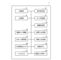
図1は、本発明の一実施形態による自動取引装置1の外観構成を示す説明図である。図2は、本発明の一実施形態による自動取引装置1の機能を示す説明図である。本発明の一実施形態による自動取引装置1は、銀行等の金融機関の支店やコンビニエンスストア等の店舗に設置され、顧客との間での取引処理を自動で行う。
Figure 1 is an explanatory diagram showing the external configuration of an
図1および図2に示したように、本発明の一実施形態による自動取引装置1は、筐体2、扉3、内部ユニット4、制御部5、記憶部6、操作表示部8、カード取扱部9、通帳取扱部9、紙幣入出金部11、硬貨入出金部12、IDカード読取部15、フロントパネル17、操作レバー18、電磁ロック機構19、生体認証センサ20、ハンドセット21、数値入力用キー22および物理ボタン23を備える。
As shown in Figures 1 and 2, an
筐体1は、自動取引装置1の外枠を構成する。筐体1の内部に、内部ユニット4、制御部5および記憶部6などが収容される。
The
扉3は、筐体1の開口を開閉する。自動取引装置1から見て顧客が位置する側を前側とすると、図1に示した例では、筐体1の前側面に扉3が設けられている。扉3が筐体1の開口を閉じている間、筐体1の内部へのアクセスが扉3により規制される。なお、図1においては扉3が自動取引装置1の前側面に位置する例を説明したが、扉3の位置は自動取引装置1の前側面に限定されず、例えば扉3は自動取引装置1の後側面に設けられてもよい。
The
内部ユニット4は、紙幣入出金部11の一部、および硬貨入出金部12の一部などを収容する。例えば、内部ユニット4は、紙幣を収納する紙幣カセット、紙幣の搬送機構、硬貨を収容する硬貨収納庫、および硬貨の搬送機構などを収容する。当該内部ユニット4は、扉3が筐体1の開口を開いている状態において、当該開口から引き出し可能に設けられている。
The
制御部5は、自動取引装置1の動作全般を制御する。例えば、制御部5は、自動取引装置1内の各部を制御して出金取引または入金取引などの取引を実行する。また、制御部5は、操作表示部8の表示を制御し、係員からの操作に基づいて電磁ロック機構19のロックを解除する。また、制御部5は、ネットワークを介して接続されるホストコンピュータとの通信を制御する。
The
記憶部6は、制御部5が実行するプログラム、プログラムの実行に用いる各種のデータ、および制御部5による処理結果等を格納する。
The
操作表示部8は、多様な表示画面を表示する表示部、および、顧客または係員により操作が行われる操作部としての機能を包含する。表示部としての機能は例えばLCDにより実現され、操作部としての機能は例えばタッチパネルにより実現される。
The
カード取扱部9は、カード挿入口9aから挿入されたカードに記録されている顧客IDや口座情報等の顧客カード情報を読み書きする。カードとしては、キャッシュカードおよびクレジットカードなどが挙げられる。顧客カード情報は、カードの磁気ストライプまたはICチップなどに記録されていてもよい。また、カード取扱部9は、明細票等に取引内容等を印刷する機能も有する。
The
紙幣入出金部10は、通帳挿入口10aから挿入された顧客の通帳の磁気ストライプ等に記録されている顧客通帳情報を読み書きする。また、紙幣入出金部10は、実行された取引の内容を顧客の通帳に記帳する。
The banknote deposit/
紙幣入出金部11は、紙幣入出金口11a、紙幣の搬送機構、紙幣の鑑別部、紙幣カセットなどを含む。入金取引においては、紙幣入出金口11aが顧客によって投入された紙幣を受入れ、鑑別部が当該紙幣を鑑別し、鑑別結果に応じた紙幣カセットに当該紙幣を搬送機構が搬送する。出金取引においては、紙幣カセットが紙幣を繰り出し、搬送機構が当該紙幣を紙幣入出金口11aに搬送し、紙幣入出金口11aが当該紙幣を排出する。
The banknote deposit/
硬貨入出金部12は、硬貨入出金口12a、硬貨の搬送機構、硬貨の鑑別部、硬貨収納庫などを含む。入金取引においては、硬貨入出金口12aが顧客によって投入された硬貨を受入れ、鑑別部が当該硬貨を鑑別し、鑑別結果に応じた硬貨収納庫に当該硬貨を搬送機構が搬送する。出金取引においては、硬貨収納庫が硬貨を放出し、搬送機構が当該硬貨を硬貨入出金口12aに搬送する。
The coin deposit/
IDカード読取部15は、銀行の行員等の係員が常に所持する係員所持カードから係員カード情報を非接触で読取る。係員カード情報としては、係員ID(係員識別子)や当該係員が作業を許可された作業資格等を示す情報が挙げられる。なお係員所持カードが磁気ストライプに係員カード情報を記憶する場合、自動取引装置1はカード取扱部9に挿入された係員所持カードから係員カード情報を読取ってもよい。
The ID
操作レバー18は、L字形状を有するレバーであり、扉3に設けられている。係員は、電磁ロック機構19によるロックが解除されている状態において操作レバー18を引くことで、扉3を開くことができる。
The operating
電磁ロック機構19は、扉3が閉じられている状態において扉3を電磁的にロックする。電磁ロック機構19は、制御部5からの指示に従って扉3のロックを解除する。なお、電磁ロック機構19はロック機構の一例であり、電磁ロック機構19に代えて他の種のロック機構が実装されてもよい。
The
生体認証センサ20は、顧客の生体情報を認証のために取得するセンサである。例えば、生体認証センサ20は、顧客の指の指紋情報または静脈情報などを生体情報として取得してもよい。
The
ハンドセット21は、顧客が係員と会話するために用いられる構成である。ハンドセット21は、係員や音声案内の音声を出力するスピーカ部、顧客の音声を収音するマイク部、およびハンドセット21を用いた操作において顧客に操作される物理的なボタンを有してもよい。
The
数値入力用キー22は、顧客が暗証番号または取引金額などの数値を入力するために設けられている。数値入力用キー22は、例えばテンキーであってもよい。物理ボタン23は、自動取引装置1を操作するために設けられている物理的なボタンである。自動取引装置1には複数の物理ボタン23が設けられていてもよい。物理ボタン23は例えば、操作表示部8の近傍に設けられ、自動取引装置1に実行させる機能を選択するためのボタンである。なお、このような数値入力用キー22および物理ボタン23が設けられる場合には、操作表示部8が操作部としての機能を包含していなくてもよい。
The
<ロックの解除方法>
本発明の一実施形態は、上述した自動取引装置1における、電磁ロック機構19によるロックの解除方法に特に関する。以下、電磁ロック機構19によるロックの解除方法を具体的に説明する。
<How to unlock>
The embodiment of the present invention particularly relates to a method for releasing the lock by the
係員は、扉3を開いて内部ユニット4を自動取引装置1内から引き出すことで、自動取引装置1の保守を行い得る。当該保守のために、係員は、まず、係員所持カードをIDカード読取部15にかざす。IDカード読取部15が係員所持カードから係員カード情報を読み取ると、制御部5が係員カード情報に基づいて係員が正当な権限を有するか否かを判断する。
An attendant can perform maintenance on the
係員が正当な権限を有する場合、制御部5は、電磁ロック機構19によるロックを解除するための解除操作画面を生成し、当該解除操作画面を操作表示部8に表示させる。制御部5は、ユーザの一例である係員の手指により第1の操作および第2の操作が解除操作画面において同時に行われていることに基づき、電磁ロック機構19に扉3のロックを解除させる。
If the attendant has proper authority, the
解除操作画面は、第1のオブジェクトおよび第2のオブジェクトを含み、上記第1の操作は第1のオブジェクトへの操作であり、上記第2の操作は第2のオブジェクトへの操作である。以下、図3を参照し、このような解除操作画面の具体例を説明する。 The release operation screen includes a first object and a second object, the first operation being an operation on the first object, and the second operation being an operation on the second object. Below, a specific example of such a release operation screen will be described with reference to FIG. 3.
図3は、解除操作画面40の具体例を示す説明図である。図3に示したように、解除操作画面40は、案内メッセージ42、扉開ボタン44A、扉開ボタン44Bおよび戻るボタン46を含む。案内メッセージ42は、扉開ボタン44Aおよび扉開ボタン44Bを同時に操作することを誘導するメッセージである。戻るボタン46は、操作手順を戻る場合に係員に操作されるボタンである。
Figure 3 is an explanatory diagram showing a specific example of the
扉開ボタン44Aは第1のオブジェクトの一例であり、扉開ボタン44Bは第2のオブジェクトの一例である。扉開ボタン44Aおよび扉開ボタン44Bは、電磁ロック機構19によるロックを解除するために係員により操作されるボタンである。
The door
これら扉開ボタン44Aの表示位置と扉開ボタン44Bの表示位置は、図3に示したように距離dだけ離隔している。距離dは、片手の手指では扉開ボタン44Aに触れつつ扉開ボタン44Bに触れることができない距離である。距離dは、例えば15cm以上であってもよい。従って、係員は、扉開ボタン44Aおよび扉開ボタン44Bの同時の操作のために、一方の手の手指で扉開ボタン44Aを操作しつつ、他方の手の手指で扉開ボタン44Bを操作する必要がある。
The display positions of the door
制御部6は、扉開ボタン44Aへの操作および扉開ボタン44Bへの操作が同時に行われている場合に、電磁ロック機構19に扉3のロックを解除させる。
The
なお、扉開ボタン44Aへの操作および扉開ボタン44Bへの操作が同時に行われていることは、扉開ボタン44Aへの操作が検出されたタイミングと、扉開ボタン44Bへの操作が検出されたタイミングとが一致することであってもよい。または、扉開ボタン44Aへの操作および扉開ボタン44Bへの操作が同時に行われていることは、扉開ボタン44Aへの操作が行われている時間幅と、扉開ボタン44Bへの操作が行われている時間幅とが、所定の長さ以上に亘って重なっていることであってもよい。
Note that the operation of the door
<作用効果>
以上説明した本発明の一実施形態によれば、多様な作用効果が得られる。例えば、本発明の一実施形態では、扉開ボタン44Aへの操作および扉開ボタン44Bへの操作が同時に行われている場合に、電磁ロック機構19が扉3のロックを解除する。扉開ボタン44Aへの操作および扉開ボタン44Bへの操作が同時に行うために、係員は、一方の手の手指で扉開ボタン44Aを操作しつつ、他方の手の手指で扉開ボタン44Bを操作することが考えられる。この場合、係員は、扉開ボタン44Aおよび扉開ボタン44Bを操作している間に扉3を開ける方向への力をかけられないので、摩擦力によりロックが解除されないという事象の発生を防止することが可能である。また扉(または内部ユニット)にかかる力によって電磁ロックが破損することを防止することが可能である。
<Action and effect>
According to the embodiment of the present invention described above, various actions and effects can be obtained. For example, in one embodiment of the present invention, when the door
また、扉開ボタン44Aの表示位置と扉開ボタン44Bの表示位置は、片手の手指では扉開ボタン44Aに触れつつ扉開ボタン44Bに触れることができない距離だけ離れている。従って、係員は、扉開ボタン44Aおよび扉開ボタン44Bの同時の操作のために、一方の手の手指で扉開ボタン44Aを操作しつつ、他方の手の手指で扉開ボタン44Bを操作する必要がある。このため、摩擦力によりロックが解除されないという事象の発生をより確実に防止することが可能である。また扉(または内部ユニット)にかかる力によって電磁ロックが破損することを確実に防止することが可能である。
In addition, the display positions of door
<変形例>
以上、本発明の一実施形態を説明した。以下では、上述した実施形態の幾つかの変形例を説明する。なお、以下に説明する各変形例は、単独で上述した実施形態に適用されてもよいし、組み合わせで上述した実施形態に適用されてもよい。また、各変形例は、上述した実施形態の構成に代えて適用されてもよいし、上述した実施形態の構成に対して追加的に適用されてもよい。
<Modification>
An embodiment of the present invention has been described above. In the following, some modified examples of the above-described embodiment will be described. Note that each modified example described below may be applied alone to the above-described embodiment, or may be applied in combination to the above-described embodiment. Also, each modified example may be applied in place of the configuration of the above-described embodiment, or may be applied in addition to the configuration of the above-described embodiment.
例えば、上記では、第1の操作が扉開ボタン44Aへの操作であり、上記第2の操作が
扉開ボタン44Bへの操作である例を説明したが、第1の操作と第2の操作の組み合わせは上記の例に限定されない。自動取引装置1は、第1の操作部および第2の操作部を有し、第1の操作は第1の操作部に対する操作であり、第2の操作は、第2の操作部に対する操作であってもよい。
For example, in the above example, the first operation is an operation on the door-
より具体的には、第1の操作部は、生体認証センサ20、ハンドセット21、数値入力用キー22、操作表示部8または物理ボタン23のいずれかであり、第2の操作部は、生体認証センサ20、ハンドセット21、数値入力用キー22、操作表示部8または物理ボタン23のいずれかであり、かつ、第1の操作部と異なる種類の操作部であってもよい。
More specifically, the first operation unit is one of the
第1の操作部が操作表示部8であり、第2の操作部が生体認証センサ20である場合、制御部5は、例えば以下に示す解除操作画面50を生成し、当該解除操作画面を操作表示部8に表示させてもよい。
When the first operation unit is the
図4は解除操作画面50の具体例を示す説明図である。図4に示したように、解除操作画面50は、案内メッセージ52、扉開ボタン54、および戻るボタン56を含む。案内メッセージ52は、扉開ボタン54および生体認証センサ20を同時に操作することを誘導するメッセージである。戻るボタン56は、操作手順を戻る場合に係員に操作されるボタンである。解除操作画面50が表示されている間に、係員が扉開ボタン54を押しながら生体認証センサ20に指を当てると、制御部5は電磁ロック機構19に扉3のロックを解除させる。
Figure 4 is an explanatory diagram showing a specific example of the
また他の例として、第1の操作部が操作表示部8であり、第2の操作部がハンドセット21である場合も、上述と同様に解除操作画面(図示せず)を生成して表示し、扉開ボタンおよびハンドセット21を同時に操作することを誘導する。第1の操作部が操作表示部8であり、第2の操作部が数値入力用キー22、または物理ボタン23である場合も同様である。
As another example, when the first operation unit is the
更に、第1の操作部および第2の操作部のいずれも操作表示部8ではない態様であってもよい。即ち、第一の操作部が生体認証センサ20、ハンドセット21、数値入力用キー22、物理ボタン23のいずれかであり、第2の操作部は、生体認証センサ20、ハンドセット21、数値入力用キー22、操作表示部8、物理ボタン23のいずれかであり、かつ、第1の操作部と異なる種類の操作部であってもよい。この場合も上述と同様に解除操作画面(図示せず)が表示され、電磁ロック機構19によるロックを解除するために第1の操作部と第2の操作部を同時に操作することを誘導する。なおこの場合の第1の操作部と第2の操作部の組み合わせは、係員が片手の手指にて第一の操作部を操作しつつ第二の操作部を操作することができない(操作することが困難である)ことが好適である。
Furthermore, neither the first nor the second operation unit may be the
このような変形例においても、係員は、第1の操作および第2の操作を行うために両手を使うので、摩擦力によりロックが解除されないという事象の発生を防止することが可能である。 Even in this type of modification, the attendant uses both hands to perform the first and second operations, making it possible to prevent the lock from failing to be released due to friction.
他の例として、第1の操作部と第2の操作部の種類は同じであってもよい。例えば、第1の操作部は第1の物理ボタンであり、第2の操作部は第1の物理ボタンと異なる第2の物理ボタンであってもよい。このとき、第1の物理ボタンと第2の物理ボタンとが、係員が片手の手指で、第1の物理ボタンに触れつつ第2の第1の物理ボタンに触れることができない距離だけ離れていれば、摩擦力によりロックが解除されないという事象の発生をより確実に防止することが可能である。また扉(または内部ユニット)にかかる力によって電磁ロックが破損することを確実に防止することが可能である。 As another example, the first operation unit and the second operation unit may be the same type. For example, the first operation unit may be a first physical button, and the second operation unit may be a second physical button different from the first physical button. In this case, if the first physical button and the second physical button are separated by a distance such that an attendant cannot touch the first physical button and the second first physical button with the fingers of one hand, it is possible to more reliably prevent the occurrence of an event in which the lock is not released due to frictional force. It is also possible to reliably prevent the electromagnetic lock from being damaged by force applied to the door (or the internal unit).
また、上記では電磁ロック機構19によるロックの対象が扉3である例を説明したが、他の対象にも本発明の実施形態を適用することが可能である。例えば、電磁ロック機構19によるロックの対象は、内部ユニット4であってもよい。すなわち、電磁ロック機構19は、内部ユニット4が筐体2に収納された状態で内部ユニット2の引き出しをロックにより制限してもよい。かかる構成では、係員が内部ユニット4を引き出す方向に力をかけることで生じる摩擦力によりロックが解除されないという事象の発生を防止することが可能である。ロックの対象を内部ユニット4とする場合、物理ボタン23は、筐体1の内部に係員が操作可能なように設けられた一つまたは複数の操作ボタン(スイッチ)であってもよい。
Although the above describes an example in which the target of the locking by the
<他の実施形態>
上記では、本発明の一実施形態として自動取引装置1を説明した。以下では、他の実施形態として、現金処理装置100の構成および動作を説明する。現金処理装置100は、例えば、スーパーマーケットやコンビニエンスストア等の小売店やディスカウントショップ等の大型量販店等の精算所に設置されたレジスタやPOS(Point Of Sales)用レジスタ等に接続された現金釣銭機である
<Other embodiments>
In the above, the
(構成)
図5は、現金処理装置100の構成を示す斜視図である。図6は、装置本体114が筐体112から引き出された状態を示す図である。
(composition)
Fig. 5 is a perspective view showing the configuration of the
筐体112は、装置本体114を収納する例えば金属製のケースである。装置本体114は、現金である硬貨や紙幣の入出金を管理する。装置本体114は、幅方向の両側にガイドレール115を有し、ガイドレール115に沿って筐体12に対して引き出し又は挿入される。装置本体114は、図示しない電磁ロック機構により、筐体112に挿入された状態でロックされる。当該ロックが解除されることにより、装置本体114は筐体112から引き出し可能となる。
The
また、装置本体114は、図6に示すように、硬貨処理ユニット120と、紙幣処理ユニット130と、操作部140と、表示部150と、を有する。なお、図6においては、硬貨処理ユニット120および紙幣処理ユニット130を有する装置本体114が一体的に引き出される例を示しているが、硬貨処理ユニット120および紙幣処理ユニット130は個別に引き出し可能であってもよい。
As shown in FIG. 6, the device
硬貨処理ユニット120は、図6に示すように幅方向の一端側の半分に設けられ、硬貨の入出金を行う。硬貨処理ユニット120は、装置の前方に、投入部122、及び排出部123を有する。投入部122は、操作者により入金硬貨が投入される投入口の機能を有する。排出部123は、装置内から出金硬貨が排出される排出口の機能を有する。
The
紙幣処理ユニット130は、図6に示すように幅方向の他端側の半分に設けられ、紙幣の入出金を行う。紙幣処理ユニット130は、装置の前方に、紙幣の投入排出部132を有する。投入排出部132は、入金紙幣の投入口と、出金紙幣の出金口の機能を有する。投入排出部132の下方には、カセット133が紙幣処理ユニット130から着脱可能に設けられる。このカセット133は、紙幣処理ユニット130から種々の目的(例えば紙幣の回収)で紙幣を取り出すために用いられる。このカセット133は図示しない機械式の鍵で紙幣処理ユニット130に固定されている。
The
押ボタン140は、操作者の操作を受け付ける。例えば、操作者は、押ボタン140の押圧により、操作表示部150に表示された選択画面にて所望の項目を選択してもよい。
The
操作表示部150は、多様な画面を表示する表示部としての機能、および操作者により操作が行われる操作部としての機能を有する。操作表示部150は、例えばタッチパネルであってもよい。
The
このような現金処理装置100は、別装置であるレジスタ装置(例えばPOS端末)(図示せず)と通信可能に接続される。現金処理装置100はレジスタ装置からの制御を受けて動作することもできる。なお、レジスタ装置もタッチパネル式の操作表示部を有していてもよい。
Such a
(動作)
続いて、現金処理装置100における装置本体114のロックの解除方法を説明する。
(Operation)
Next, a method for unlocking the device
現金処理装置100は、電磁ロック機構による装置本体114のロックを解除するための解除操作画面を生成し、当該解除操作画面を操作表示部150に表示させる。解除操作画面は、上述した実施形態と同様に、2つの扉開ボタンを含んでもよい。この場合、現金処理装置100は、2つの扉開ボタンへの操作が同時に行われている場合に、電磁ロック機構に装置本体114のロックを解除させる。
The
または、解除操作画面は1つの扉開ボタンを含んでもよい。この場合、現金処理装置100は、当該扉開ボタンへの操作と、他のハードボタン(例えば、押ボタン140)への操作が同時に行われている場合に、電磁ロック機構に装置本体114のロックを解除させる。
Alternatively, the release operation screen may include one door open button. In this case, the
または、解除操作画面は、現金処理装置100に設けられた2つのハードボタンを同時に操作することを誘導する画面であってもよい。この場合、現金処理装置100は、2つのハードボタン(例えば、2つの押ボタン140)への操作が同時に行われている場合に、電磁ロック機構に装置本体114のロックを解除させる。
Alternatively, the release operation screen may be a screen that guides the user to simultaneously operate two hard buttons provided on the
または、現金処理装置100は、レジスタ装置から受信される制御信号に基づき、電磁ロック機構に装置本体114のロックを解除させてもよい。レジスタ装置は、上述したいずれかの例による解除操作画面をレジスタ装置の操作表示部に表示し、操作者により解除操作(例えば、2つの扉開ボタンへの操作)が行われた場合に、現金処理装置100に制御信号を送信してもよい。この場合、現金処理装置100とレジスタ装置を一体的に1つの装置と捉えることもできる。
Alternatively, the
または、現金処理装置100は、現金処理装置100への操作とレジスタ装置への操作に基づき、電磁ロック機構に装置本体114のロックを解除させてもよい。例えば、レジスタ装置の操作表示部が第1の扉開ボタンを表示し、現金処理装置100の操作表示部150が第2の扉開ボタンを表示し、現金処理装置100は、第1の扉開ボタンへの操作および第2の扉開ボタンへの操作が同時に行われている場合に、電磁ロック機構に装置本体114のロックを解除させてもよい。
Alternatively, the
なお、紙幣処理ユニット130において投入排出部132の下方に設けられるカセット133の固定に、機械式の鍵に代えて、電磁ロック機構が適用されてもよい。この場合、上述した電磁ロック機構による装置本体114のロックの解除方法を、電磁ロック機構によるカセット133のロックの解除に適用することが可能である。
In addition, an electromagnetic locking mechanism may be used instead of a mechanical key to secure the
(作用効果)
当該実施形態においても、自動取引装置1の実施形態と同様に、操作者が、電磁ロック機構を解除するための第1の操作を一方の手で行い、第2の操作を他方の手で行うことが考えられる。この場合、操作者は、第1の操作および第2の操作を行っている間に装置本体114を引き出す方向への力をかけられないので、摩擦力によりロックが解除されないという事象の発生を防止することが可能である。装置本体114にかかる力によって電磁ロック機構が破損することを防止することも可能である。
(Action and Effect)
In this embodiment, as in the embodiment of the
<補足>
以上、添付図面を参照しながら本発明の好適な実施形態について詳細に説明したが、本発明はかかる例に限定されない。本発明の属する技術の分野における通常の知識を有する者であれば、特許請求の範囲に記載された技術的思想の範疇内において、各種の変更例または修正例に想到し得ることは明らかであり、これらについても、当然に本発明の技術的範囲に属するものと了解される。
<Additional Information>
Although the preferred embodiment of the present invention has been described in detail above with reference to the accompanying drawings, the present invention is not limited to such an example. It is clear that a person having ordinary knowledge in the technical field to which the present invention pertains can conceive of various modified or altered examples within the scope of the technical ideas described in the claims, and it is understood that these also naturally belong to the technical scope of the present invention.
例えば、自動取引装置1に内蔵されるCPU、ROMおよびRAMなどのハードウェアに、上述した自動取引装置1の各構成と同等の機能を発揮させるためのコンピュータプログラムも作成可能である。また、該コンピュータプログラムを記憶させた記憶媒体も提供される。
For example, a computer program can be created to cause hardware such as the CPU, ROM, and RAM built into the
1 自動取引装置
2 筐体
3 扉
4 内部ユニット
5 制御部
6 記憶部
8 操作表示部
9 カード取扱部
10 通帳取扱部
11 紙幣入出金部
12 硬貨入出金部
15 IDカード読取部
19 電磁ロック機構
20 生体認証センサ
21 ハンドセット
22 数値入力用キー
23 物理ボタン
100 現金処理装置
112 筐体
114 装置本体
120 硬貨処理ユニット
130 紙幣処理ユニット
140 押ボタン
150 操作表示部
Claims (3)
前記収納庫へのアクセスを規制する、前記筐体に設けられた扉と、
前記扉が閉じられた状態で前記扉をロックし、前記扉のロックの実施および解除が電磁的に制御されるロック機構と、
第1のオブジェクトおよび第2のオブジェクトを表示するものであって、前記第1のオブジェクトの表示位置と前記第2のオブジェクトの表示位置との距離は、ユーザの片手の手指では前記第1のオブジェクトに触れつつ前記第2のオブジェクトに触れることができず、前記ユーザが両手の手指のそれぞれで前記第1のオブジェクトに触れつつ前記第2のオブジェクトに触れることが必要となる距離である、表示部と、
前記扉に設けられるものであって、前記ロック機構による前記扉のロックが電磁的に解除された状態で前記ユーザが把持して前記扉を開閉可能であり、また前記ユーザが両手の手指のそれぞれで前記第1のオブジェクトに触れつつ前記第2のオブジェクトに触れるときには把持できない位置に設けられる把持部と、
前記ユーザの手指により、前記第1のオブジェクトへ第1の接触操作が行われ、同時に前記第2のオブジェクトへ第2の接触操作が行われていることに基づき、前記ロック機構に前記扉のロックを解除させる制御部と、
を備える、自動取引装置。 A housing having a storage compartment therein for storing cash ;
a door provided on the housing for restricting access to the storage unit ;
a lock mechanism that locks the door when the door is closed and that electromagnetically controls the locking and unlocking of the door ;
a display unit that displays a first object and a second object, the distance between a display position of the first object and a display position of the second object being such that a user is unable to touch the first object and the second object at the same time with the fingers of one hand of the user, and the user is required to touch the first object and the second object with the fingers of both hands, respectively;
a gripping portion that is provided on the door and that can be grasped by the user to open and close the door in a state where the door is electromagnetically released from the locking mechanism, and that is provided at a position that cannot be grasped by the user when the user is touching the second object while touching the first object with each of the fingers of both hands;
a control unit that causes the lock mechanism to unlock the door based on a first contact operation being performed on the first object and a second contact operation being performed on the second object by the user's finger at the same time ;
An automated transaction device comprising:
内部に現金を収納する収納庫を備える筐体と、
前記収納庫へのアクセスを規制する、前記筐体に設けられた扉と、
前記扉が閉じられた状態で前記扉をロックし、前記扉のロックの実施および解除が電磁的に制御されるロック機構と、
生体認証センサ、数値入力用キー、ハンドセット、タッチパネルまたは前記自動取引装置を操作するための物理ボタンのいずれかである第1の操作部と、
生体認証センサ、数値入力用キー、ハンドセット、タッチパネルまたは前記自動取引装置を操作するための物理ボタンのいずれかであり、かつ、前記第1の操作部と異なる種類の操作部である第2の操作部と、
前記扉に設けられるものであって、前記ロック機構による前記扉のロックが電磁的に解除された状態でユーザが把持して前記扉を開閉可能であり、また前記ユーザが両手の手指のそれぞれで前記第1の操作部に触れつつ前記第2の操作部に触れるときには把持できない位置に設けられる把持部と、
前記ユーザの手指により、前記第1の操作部へ第1の接触操作が行われ、同時に前記第2の操作部へ第2の接触操作が行われていることに基づき、前記ロック機構に前記扉のロックを解除させる制御部と、
を備え、
前記第1の操作部と前記第2の操作部との距離は、前記ユーザの片手の手指では前記第1の操作部に触れつつ前記第2の操作部に触れることができず、前記ユーザが両手の手指のそれぞれで前記第1の操作部に触れつつ前記第2の操作部に触れることが必要となる距離である、自動取引装置。 An automated transaction device,
A housing having a storage compartment therein for storing cash ;
a door provided on the housing for restricting access to the storage unit ;
a lock mechanism that locks the door when the door is closed and that electromagnetically controls the locking and unlocking of the door ;
a first operation unit which is any one of a biometric authentication sensor, a numeric input key, a handset, a touch panel, and a physical button for operating the automated transaction device;
a second operation unit which is a biometric authentication sensor, a numeric input key, a handset, a touch panel, or a physical button for operating the automated transaction device and is a different type of operation unit from the first operation unit;
a gripping portion that is provided on the door and that can be grasped by a user to open and close the door in a state where the door is electromagnetically released from the locking mechanism, and that is provided at a position that cannot be grasped by the user when the user is touching the second operation portion while touching the first operation portion with each of the fingers of both hands;
a control unit that causes the lock mechanism to unlock the door based on a first contact operation being performed on the first operation unit and a second contact operation being performed on the second operation unit at the same time by a finger of the user ;
Equipped with
An automatic transaction device, wherein the distance between the first operation unit and the second operation unit is such that the user cannot touch the first operation unit and the second operation unit at the same time with the fingers of one hand, and the user must touch the first operation unit and the second operation unit at the same time with the fingers of both hands .
前記ユーザの手指により、前記第1のオブジェクトへ第1の接触操作が行われ、同時に前記第2のオブジェクトへ第2の接触操作が行われていることに基づき、前記ロック機構に前記扉のロックを解除させる制御部と、
として機能させるための、プログラム。
an automated transaction machine comprising: a housing having a storage unit for storing cash therein ; a door provided in the housing for restricting access to the storage unit ; a locking mechanism for locking the door when the door is closed and for electromagnetically controlling the locking and unlocking of the door ; a display unit for displaying a first object and a second object, the display unit being positioned so that a distance between a display position of the first object and a display position of the second object is such that a user is unable to touch the first object and the second object at the same time with the fingers of one hand of the user, and the user is required to touch the first object and the second object with each of the fingers of both hands; and a grip unit provided on the door, the user being able to hold the door to open and close the door when the door is electromagnetically unlocked by the locking mechanism, and the grip unit being provided at a position where the user cannot hold the door when the user is touching the first object and the second object with each of the fingers of both hands .
a control unit that causes the lock mechanism to unlock the door based on a first contact operation being performed on the first object and a second contact operation being performed on the second object by the user's finger at the same time ;
A program to function as a
Priority Applications (1)
| Application Number | Priority Date | Filing Date | Title |
|---|---|---|---|
| JP2021023435A JP7608859B2 (en) | 2021-02-17 | 2021-02-17 | Automatic transaction device and program |
Applications Claiming Priority (1)
| Application Number | Priority Date | Filing Date | Title |
|---|---|---|---|
| JP2021023435A JP7608859B2 (en) | 2021-02-17 | 2021-02-17 | Automatic transaction device and program |
Publications (2)
| Publication Number | Publication Date |
|---|---|
| JP2022125698A JP2022125698A (en) | 2022-08-29 |
| JP7608859B2 true JP7608859B2 (en) | 2025-01-07 |
Family
ID=83058292
Family Applications (1)
| Application Number | Title | Priority Date | Filing Date |
|---|---|---|---|
| JP2021023435A Active JP7608859B2 (en) | 2021-02-17 | 2021-02-17 | Automatic transaction device and program |
Country Status (1)
| Country | Link |
|---|---|
| JP (1) | JP7608859B2 (en) |
Citations (4)
| Publication number | Priority date | Publication date | Assignee | Title |
|---|---|---|---|---|
| JP2012150644A (en) | 2011-01-19 | 2012-08-09 | Laurel Precision Machines Co Ltd | Currency processing machine |
| JP2016095674A (en) | 2014-11-14 | 2016-05-26 | 沖電気工業株式会社 | Automatic transaction equipment |
| JP2017191560A (en) | 2016-04-15 | 2017-10-19 | 株式会社デジアイズ | Input control device, electronic register, and pos register |
| JP2017228116A (en) | 2016-06-23 | 2017-12-28 | ローレル精機株式会社 | Currency processing apparatus |
-
2021
- 2021-02-17 JP JP2021023435A patent/JP7608859B2/en active Active
Patent Citations (4)
| Publication number | Priority date | Publication date | Assignee | Title |
|---|---|---|---|---|
| JP2012150644A (en) | 2011-01-19 | 2012-08-09 | Laurel Precision Machines Co Ltd | Currency processing machine |
| JP2016095674A (en) | 2014-11-14 | 2016-05-26 | 沖電気工業株式会社 | Automatic transaction equipment |
| JP2017191560A (en) | 2016-04-15 | 2017-10-19 | 株式会社デジアイズ | Input control device, electronic register, and pos register |
| JP2017228116A (en) | 2016-06-23 | 2017-12-28 | ローレル精機株式会社 | Currency processing apparatus |
Also Published As
| Publication number | Publication date |
|---|---|
| JP2022125698A (en) | 2022-08-29 |
Similar Documents
| Publication | Publication Date | Title |
|---|---|---|
| JP5387514B2 (en) | Banknote handling equipment | |
| JP5047257B2 (en) | Automatic transaction processing apparatus and automatic transaction processing system | |
| JP5583534B2 (en) | Automatic transaction equipment | |
| CN101894425B (en) | Automatic transaction device | |
| JP5182169B2 (en) | Automatic transaction equipment | |
| JP5974812B2 (en) | Cash processing equipment | |
| WO2006067858A1 (en) | Coin-receiving and -dispensing machine | |
| JP5115377B2 (en) | Automatic transaction equipment | |
| JP6291905B2 (en) | Money processing equipment | |
| JP7608859B2 (en) | Automatic transaction device and program | |
| JP5564767B2 (en) | Automatic transaction equipment | |
| JP4769852B2 (en) | Automatic transaction equipment | |
| JP5625773B2 (en) | Automatic transaction equipment | |
| JP6405926B2 (en) | Automatic transaction equipment | |
| JP5202152B2 (en) | Cash processing system | |
| JP4611344B2 (en) | Automatic transaction equipment | |
| JP6208007B2 (en) | Cash deposit / withdrawal machine, sales collection method, and program | |
| JP6277747B2 (en) | Deposit / withdrawal device and deposit / withdrawal program | |
| JP6435954B2 (en) | Cash processing equipment | |
| JP5458736B2 (en) | Automated trading system | |
| JP2024112346A (en) | Currency handling equipment | |
| JP6756117B2 (en) | Cash processing device | |
| JP6863186B2 (en) | Media processing equipment and automated teller machines | |
| JP2024090357A (en) | Unit storage device and cash handling device | |
| JP6561356B2 (en) | Money handling machine |
Legal Events
| Date | Code | Title | Description |
|---|---|---|---|
| A621 | Written request for application examination |
Free format text: JAPANESE INTERMEDIATE CODE: A621 Effective date: 20231109 |
|
| A977 | Report on retrieval |
Free format text: JAPANESE INTERMEDIATE CODE: A971007 Effective date: 20240628 |
|
| A131 | Notification of reasons for refusal |
Free format text: JAPANESE INTERMEDIATE CODE: A131 Effective date: 20240709 |
|
| A521 | Request for written amendment filed |
Free format text: JAPANESE INTERMEDIATE CODE: A523 Effective date: 20240909 |
|
| TRDD | Decision of grant or rejection written | ||
| A01 | Written decision to grant a patent or to grant a registration (utility model) |
Free format text: JAPANESE INTERMEDIATE CODE: A01 Effective date: 20241119 |
|
| A61 | First payment of annual fees (during grant procedure) |
Free format text: JAPANESE INTERMEDIATE CODE: A61 Effective date: 20241202 |
|
| R150 | Certificate of patent or registration of utility model |
Ref document number: 7608859 Country of ref document: JP Free format text: JAPANESE INTERMEDIATE CODE: R150 |