JP7607828B2 - Knotter device - Google Patents

Knotter device Download PDF

Info

Publication number
JP7607828B2
JP7607828B2 JP2024511460A JP2024511460A JP7607828B2 JP 7607828 B2 JP7607828 B2 JP 7607828B2 JP 2024511460 A JP2024511460 A JP 2024511460A JP 2024511460 A JP2024511460 A JP 2024511460A JP 7607828 B2 JP7607828 B2 JP 7607828B2
Authority
JP
Japan
Prior art keywords
yarn
thread
old
hook
stitch
Prior art date
Legal status (The legal status is an assumption and is not a legal conclusion. Google has not performed a legal analysis and makes no representation as to the accuracy of the status listed.)
Active
Application number
JP2024511460A
Other languages
Japanese (ja)
Other versions
JPWO2023189041A1 (en
Inventor
大雅 小松原
元 山口
政裕 ▲高▼田
基晴 中嶋
芳樹 田端
Current Assignee (The listed assignees may be inaccurate. Google has not performed a legal analysis and makes no representation or warranty as to the accuracy of the list.)
Shima Seiki Mfg Ltd
Original Assignee
Shima Seiki Mfg Ltd
Priority date (The priority date is an assumption and is not a legal conclusion. Google has not performed a legal analysis and makes no representation as to the accuracy of the date listed.)
Filing date
Publication date
Application filed by Shima Seiki Mfg Ltd filed Critical Shima Seiki Mfg Ltd
Publication of JPWO2023189041A1 publication Critical patent/JPWO2023189041A1/ja
Application granted granted Critical
Publication of JP7607828B2 publication Critical patent/JP7607828B2/en
Active legal-status Critical Current
Anticipated expiration legal-status Critical

Links

Images

Classifications

    • BPERFORMING OPERATIONS; TRANSPORTING
    • B65CONVEYING; PACKING; STORING; HANDLING THIN OR FILAMENTARY MATERIAL
    • B65HHANDLING THIN OR FILAMENTARY MATERIAL, e.g. SHEETS, WEBS, CABLES
    • B65H69/00Methods of, or devices for, interconnecting successive lengths of material; Knot-tying devices ;Control of the correct working of the interconnecting device
    • B65H69/04Methods of, or devices for, interconnecting successive lengths of material; Knot-tying devices ;Control of the correct working of the interconnecting device by knotting
    • DTEXTILES; PAPER
    • D01NATURAL OR MAN-MADE THREADS OR FIBRES; SPINNING
    • D01HSPINNING OR TWISTING
    • D01H15/00Piecing arrangements ; Automatic end-finding, e.g. by suction and reverse package rotation; Devices for temporarily storing yarn during piecing
    • BPERFORMING OPERATIONS; TRANSPORTING
    • B65CONVEYING; PACKING; STORING; HANDLING THIN OR FILAMENTARY MATERIAL
    • B65HHANDLING THIN OR FILAMENTARY MATERIAL, e.g. SHEETS, WEBS, CABLES
    • B65H2701/00Handled material; Storage means
    • B65H2701/30Handled filamentary material
    • B65H2701/31Textiles threads or artificial strands of filaments

Landscapes

  • Engineering & Computer Science (AREA)
  • Mechanical Engineering (AREA)
  • Textile Engineering (AREA)
  • Knitting Machines (AREA)

Description

本発明は、糸選択部及び糸継ぎ部を具備するノッター装置の技術に関する。 The present invention relates to technology for a knotter device having a thread selection section and a thread joining section.

従来、糸選択部及び糸継ぎ部を具備するノッター装置の技術は公知となっている。ノッター装置を用いることで、使用中の糸を色などが異なる他の糸に切り替えることができる。 Conventionally, the technology of a knotter device equipped with a thread selection section and a thread splicing section has been publicly known. By using the knotter device, the thread being used can be switched to another thread of a different color, etc.

特許文献1には、作業終了後の第1糸を切断した終端部と、次の作業の第2糸の始端部と、を糸結びする糸結び装置が開示されている。上記糸結び装置においては、捻り目に対して編目を形成する過程で糸ガイドを用いずに、編針の回転とべらの作用により編目を形成するため、編目を形成する際の安定性の点で問題があった。 Patent document 1 discloses a yarn tying device that ties the end of a cut first yarn after a work is completed to the starting end of a second yarn for the next work. In the yarn tying device, no yarn guide is used in the process of forming stitches on a twisted stitch, but stitches are formed by the rotation of the knitting needle and the action of the latch, which creates a problem in terms of stability when forming stitches.

特開2002-35460号公報JP 2002-35460 A

本発明は以上の如き状況に鑑みてなされたものであり、その解決しようとする課題は、はた結びを安定して行うことができるノッター装置を提供することである。The present invention was made in consideration of the above-mentioned circumstances, and the problem it aims to solve is to provide a knotter device that can stably tie knots.

本発明の解決しようとする課題は以上の如くであり、次にこの課題を解決するための手段を説明する。The problem that this invention aims to solve is as described above, and next we will explain the means for solving this problem.

即ち、本発明に係るノッター装置は、糸選択部及び糸継ぎ部を具備するノッター装置であって、前記糸選択部は、糸源から供給される新糸を前記糸継ぎ部へ案内する案内レバーを有し、前記糸継ぎ部は、旧糸を延伸方向とは異なる方向へ案内可能な案内部と、前記旧糸を引っ掛けると共に捻って捻り目を形成し、前記案内部により案内された前記旧糸の他の部分を引っ掛けて前記捻り目を一側に通して編目を形成し、前記案内レバーにより案内された前記新糸を前記編目に通す編針と、前記編針が前記編目を形成する際に前記旧糸が巻きつけられると共に、巻きつけを解消するように動作可能なフック部と、前記新糸を通した前記編目が前記捻り目を他側に通るように前記旧糸の張力を増加させる張力付与部と、を有するものである。
このように構成することにより、はた結びを安定して行うことができる。
In other words, the knotter device of the present invention is a knotter device equipped with a yarn selection unit and a yarn splicing unit, wherein the yarn selection unit has a guide lever that guides a new yarn supplied from a yarn source to the yarn splicing unit, and the yarn splicing unit has a guide unit capable of guiding the old yarn in a direction different from the drawing direction, a knitting needle that hooks and twists the old yarn to form a twist, hooks another part of the old yarn guided by the guide unit to pass the twist through one side to form a stitch, and passes the new yarn guided by the guide lever through the stitch, a hook unit around which the old yarn is wound when the knitting needle forms the stitch and which is operable to release the winding, and a tension imparting unit that increases the tension of the old yarn so that the stitch with the new yarn passed through passes the twist through the other side.
By configuring it in this way, the knot can be tied stably.

また、前記フック部の前記旧糸への巻きつけの解消、及び、前記張力付与部による前記旧糸への張力の増加の相対的なタイミングを任意に設定可能であるものである。
このように構成することにより、糸切れや糸結びの不良の発生を抑制することができる。
In addition, the relative timing of unwinding the hook portion from the old yarn and increasing the tension on the old yarn by the tension applying portion can be set arbitrarily.
This configuration can prevent the occurrence of thread breakage and thread knotting defects.

また、前記フック部は、前記旧糸との巻きつけを解消するタイミングを任意に変更可能に構成されるものである。
このように構成することにより、糸に応じたより最適な糸結びを実現することができる。
The hook portion is configured so that the timing at which it is released from the winding with the old yarn can be changed arbitrarily.
By configuring in this way, it is possible to realize a more optimal yarn knot according to the yarn.

また、前記フック部は、前記旧糸が配置可能な一対のフック状部材を有し、
前記編針は、前記一対のフック状部材の間に進退可能かつ軸線回りに回転可能に構成されるものである。
このように構成することにより、捻り目の形成と、続く編目の形成を安定して行うことができる。
The hook portion has a pair of hook-shaped members on which the old thread can be placed,
The knitting needle is configured to be able to advance and retreat between the pair of hook-shaped members and to be able to rotate about an axis.
By configuring in this way, the formation of the twisted stitches and the subsequent formation of the stitches can be performed stably.

また、前記案内部は、前記旧糸の前記フック部よりも下流側の部分を、前記フック部を介して前記編針と対向する位置に案内するものである。
このように構成することにより、捻り目に続けて編目を形成する工程をより安定して行うことができる。
The guide portion guides a portion of the old yarn downstream of the hook portion to a position facing the knitting needle via the hook portion.
By configuring in this way, the process of forming the stitches subsequent to the twisted stitches can be carried out more stably.

また、前記新糸が前記編目に通された後、前記編目よりも上流側において前記旧糸を保持可能な保持部と、前記保持部により前記旧糸が保持された状態で、前記新糸及び前記旧糸の不要部分を切断する切断部と、を具備し、前記張力付与部は、前記切断部による切断後に前記旧糸の張力を増加させるものである。
このように構成することにより、旧糸と新糸との糸結びを効率的に行うことできる。
The yarn spool further includes a holding section capable of holding the old yarn upstream of the stitch after the new yarn has been passed through the stitch, and a cutting section that cuts unnecessary portions of the new yarn and the old yarn while the old yarn is held by the holding section, and the tension applying section increases the tension of the old yarn after it has been cut by the cutting section.
By configuring in this way, the old yarn and the new yarn can be efficiently tied together.

また、前記張力付与部は、前記案内部を含むものである。
このように構成することにより、案内部が複数の役割を兼用することにより、簡易な構成とすることができる。
The tension applying portion includes the guide portion.
With this configuration, the guide portion can serve multiple roles, resulting in a simple configuration.

また、前記編針は、前記捻り目を多重に形成するものである。
このように構成することにより、糸の結び目をより外れ難くすることができる。
The knitting needle forms the twisted stitches in multiple layers.
By configuring it in this way, the knot of the thread can be made more difficult to come undone.

本発明の効果として、はた結びを安定して行うことができる。 The effect of the present invention is that it allows for stable knot tying.

本発明の第一実施形態に係るノッター装置を示した左上方斜視図。FIG. 1 is an upper left perspective view showing a knotter device according to a first embodiment of the present invention. (a)ノッター装置を示した概略正面図。(b)糸継ぎを行うための糸を選択している状態のノッター装置を示した概略左側面図。1A is a schematic front view of the knotter device, and FIG. 1B is a schematic left side view of the knotter device in a state in which a yarn for piecing is being selected. (a)選択した糸を糸案内レバーで引っ掛けて後方へ案内している状態を示した概略正面図。(b)使用中の糸を糸案内レバーで引っ掛けてセパレータの手前へ案内している状態を示した概略正面図。1A is a schematic front view showing a state in which a selected yarn is hooked by the yarn guide lever and guided rearward, and FIG. 糸継ぎ部を示した左前方斜視図。FIG. (a)糸継ぎ部の編針、フック及び糸ガイドを示した概略平面断面図。(b)糸継ぎ部の編針、フック及び糸ガイドを示した概略左側面図。1A is a schematic cross-sectional plan view showing a knitting needle, a hook, and a yarn guide of a yarn splicing portion, and FIG. ノッター装置の構成を示したブロック図。FIG. 2 is a block diagram showing the configuration of a knotter device. 糸継ぎの工程を示したフローチャート。1 is a flowchart showing a yarn piecing process. (a)フックに旧糸を引っ掛けた状態を示した概略平面断面図。(b)フックへの旧糸の巻きつけを解消した状態を示した概略平面断面図。1A is a schematic cross-sectional plan view showing a state in which the old yarn is hooked on the hook, and FIG. 1B is a schematic cross-sectional plan view showing a state in which the old yarn is released from the hook. (a)フックに旧糸を引っ掛けた状態を示した概略左側面断面図。(b)糸ガイドによって旧糸のバッファが形成された状態を示した概略左側面断面図。(c)編針が上側フックと下側フックとの間に進入した状態を示した概略左側面断面図。(a) A schematic left side cross-sectional view showing a state in which the old yarn is hooked on the hook, (b) A schematic left side cross-sectional view showing a state in which the old yarn buffer is formed by the yarn guide, and (c) A schematic left side cross-sectional view showing a state in which the knitting needle has entered between the upper hook and the lower hook. (a)編針が上側フックと下側フックとの間から退出して旧糸を後方へ連行した状態を示した概略左側面断面図。(b)旧糸の捻り目が形成された状態を示した概略左側面断面図。(c)編針が旧糸のバッファの部分を引っ掛けた状態を示した概略左側面断面図。1A is a schematic left side cross-sectional view showing a state in which the knitting needle has retreated from between the upper hook and the lower hook and dragged the old yarn backward, FIG. 1B is a schematic left side cross-sectional view showing a state in which the old yarn has been twisted, and FIG. 1C is a schematic left side cross-sectional view showing a state in which the knitting needle has hooked the buffer portion of the old yarn. (a)旧糸の編目が形成された状態を示した概略左側面断面図。(b)旧糸が下側フックの引掛部に巻きついた状態を示した概略左側面断面図。1A is a schematic left side cross-sectional view showing a state in which a stitch of an old yarn has been formed, and FIG. 1B is a schematic left side cross-sectional view showing a state in which the old yarn has been wound around a hook portion of a lower hook. (a)新糸がフックの前方に連行された状態を示した概略左側面断面図。(b)新糸が編目に引き込まれた状態を示した概略左側面断面図。1A is a schematic left sectional view showing a state in which the new yarn is entrained in front of the hook, and FIG. 1B is a schematic left sectional view showing a state in which the new yarn is drawn into a stitch. (a)カッターが新糸及び旧糸を切断した状態を示した概略左側面断面図。(b)新糸が編針から外れた状態を示した概略左側面断面図。1A is a schematic left side cross-sectional view showing a state in which the cutter has cut the new yarn and the old yarn, and FIG. (a)新糸が捻り目の前側まで引き出された状態を示した概略左側面断面図。(b)旧糸と新糸とが糸継ぎされた状態を示した概略左側面断面図。1A is a schematic left side cross-sectional view showing a state in which the new yarn has been pulled out to the front side of the twisted loop, and FIG. (a)旧糸の捻り目が形成された状態を示した概略左側面断面図。(b)編針が上側フックと下側フックとの間に進入した状態を示した概略左側面断面図。(c)編針が上側フックと下側フックとの間に進入した状態で半回転した状態を示した概略左側面断面図。(a) A schematic left side cross-sectional view showing a state in which a twisted loop of the old yarn is formed, (b) A schematic left side cross-sectional view showing a state in which the knitting needle has entered between the upper hook and the lower hook, and (c) A schematic left side cross-sectional view showing a state in which the knitting needle has made a half turn with the knitting needle having entered between the upper hook and the lower hook. (a)編針が前方へ移動した状態を示した概略左側面断面図。(b)編針が回転途中で旧糸を引っ掛けた状態を示した概略左側面断面図。(c)捻り目が二重に形成された状態を示した概略左側面断面図。(a) A schematic left side cross-sectional view showing a state in which the knitting needle has moved forward, (b) A schematic left side cross-sectional view showing a state in which the knitting needle has caught the old yarn during rotation, and (c) A schematic left side cross-sectional view showing a state in which a double twist has been formed.

以下では、図中の矢印U、矢印D、矢印F、矢印B、矢印L及び矢印Rで示した方向を、それぞれ上方向、下方向、前方向、後方向、左方向及び右方向と定義して説明を行う。また、図中においては、図示の簡略化のため、各構成部分の図示を適宜省略している。In the following explanation, the directions indicated by the arrows U, D, F, B, L, and R in the figures are defined as the upward, downward, forward, backward, leftward, and rightward directions, respectively. In addition, in the figures, the illustration of each component has been omitted as appropriate for the sake of simplicity.

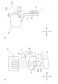
ノッター装置1は、編機において使用中の糸2と、糸源である糸コーンに巻かれた新しい糸2と、をはた結びによって糸継ぎするものである。ノッター装置1は、糸源と編機との間に配置される。より詳細には、ノッター装置1の上方には糸源が配置され、ノッター装置1の下方には編機が配置される。ノッター装置1においては、糸2が上方から下方に向けて給糸される。以下、給糸方向の上流側を「上流側」、給糸方向の下流側を「下流側」と称する。ノッター装置1は、糸選択部10、糸継ぎ部20及び制御部30を具備する。The knotter device 1 splices a thread 2 currently in use in a knitting machine with a new thread 2 wound around a thread cone, which is a thread source, by tying a hook knot. The knotter device 1 is disposed between the thread source and the knitting machine. More specifically, the thread source is disposed above the knotter device 1, and the knitting machine is disposed below the knotter device 1. In the knotter device 1, the thread 2 is fed from above downward. Hereinafter, the upstream side in the thread feeding direction is referred to as the "upstream side", and the downstream side in the thread feeding direction is referred to as the "downstream side". The knotter device 1 comprises a thread selection unit 10, a thread splicing unit 20, and a control unit 30.

図1、図2(a)及び図6等に示す糸選択部10は、糸源から供給される複数の糸2から選択された糸2を糸継ぎ部20へ案内するものである。糸選択部10は、主として、糸選択板11、糸保持12、セパレータ13、糸案内レバー14、第一糸押え15及びサクション16を具備する。The thread selection section 10 shown in Figures 1, 2(a) and 6 guides a thread 2 selected from a plurality of threads 2 supplied from a thread source to the thread splicing section 20. The thread selection section 10 mainly includes a thread selection plate 11, a thread holder 12, a separator 13, a thread guide lever 14, a first thread presser 15 and a suction 16.

糸選択板11は、糸源から供給される複数の糸2から一の糸2を選択可能に形成される。なお、糸選択板11は、糸源から供給される複数の糸2から二以上の糸2を同時に選択することもできる。以下、糸選択板11によって選択された糸2を、「新糸2a」、編機で使用中の糸2を「旧糸2b」、旧糸2b及び新糸2a以外の糸2を「待機中の糸2c」と称する。糸選択板11は、板面を左右方向に向けて複数配置される。複数の糸選択板11は、左右方向に並ぶように配置される。糸選択板11は、個別に設けられるソレノイドによって、前後に揺動可能に設けられる。糸選択板11の先端に設けられたリング11aには、糸2が挿通される。The thread selection plate 11 is formed so that one thread 2 can be selected from the multiple threads 2 supplied from the thread source. The thread selection plate 11 can also simultaneously select two or more threads 2 from the multiple threads 2 supplied from the thread source. Hereinafter, the thread 2 selected by the thread selection plate 11 is referred to as the "new thread 2a", the thread 2 being used in the knitting machine is referred to as the "old thread 2b", and the thread 2 other than the old thread 2b and the new thread 2a is referred to as the "standby thread 2c". A plurality of thread selection plates 11 are arranged with the plate surface facing left and right. The multiple thread selection plates 11 are arranged so that they are lined up in the left and right direction. The thread selection plate 11 is provided so that it can swing back and forth by a solenoid provided individually. The thread 2 is inserted into the ring 11a provided at the tip of the thread selection plate 11.

糸保持12は、糸選択板11よりも下流側に設けられる。糸保持12は、糸2を保持する保持位置と、糸2を保持しない退避位置と、に変位可能に形成される。糸保持12は、例えば空気圧で変位可能に形成される。糸保持12は、保持位置において、複数の糸2の先端付近を同時に保持することができる。より詳細には、糸保持12は、旧糸2b以外の複数の糸2を同時に保持することができる。The thread holder 12 is provided downstream of the thread selection plate 11. The thread holder 12 is formed so that it can be displaced between a holding position where it holds the thread 2 and a retracted position where it does not hold the thread 2. The thread holder 12 is formed so that it can be displaced, for example, by air pressure. In the holding position, the thread holder 12 can simultaneously hold the vicinity of the tips of multiple threads 2. More specifically, the thread holder 12 can simultaneously hold multiple threads 2 other than the old thread 2b.

セパレータ13は、給糸方向において、糸選択板11と糸保持12との間に配置される。セパレータ13は、板面を前後方向に向けた板状に形成される。セパレータ13は、旧糸2bと待機中の糸2cとを隔てることができる。具体的には、旧糸2bは、セパレータ13の後側を通って下方に導かれる。待機中の糸2は、糸選択板11の先端のリング11aを通って、セパレータ13の前側を通り、糸保持12で保持される。The separator 13 is disposed between the yarn selection plate 11 and the yarn holder 12 in the yarn feeding direction. The separator 13 is formed in a plate shape with the plate surface facing in the front-to-rear direction. The separator 13 can separate the old yarn 2b from the waiting yarn 2c. Specifically, the old yarn 2b passes through the rear side of the separator 13 and is guided downward. The waiting yarn 2 passes through the ring 11a at the tip of the yarn selection plate 11, passes the front side of the separator 13, and is held by the yarn holder 12.

糸案内レバー14は、糸選択板11により選択された新糸2aを糸継ぎ部20へ案内可能に形成される。糸案内レバー14は、前後方向に延びる軸線回りに回動可能に設けられる。糸案内レバー14は、例えばモータによって駆動される。図3(a)に示すように、糸案内レバー14は、回動の途中で先端14aにおいて新糸2aを引っ掛けることができる。糸案内レバー14の中間部には、側面突起14bが設けられる。図3(a)に示すように、糸案内レバー14は、回動の途中で側面突起14bにおいて旧糸2bを引っ掛けることができる。The thread guide lever 14 is formed so as to be able to guide the new thread 2a selected by the thread selection plate 11 to the thread splicing section 20. The thread guide lever 14 is provided so as to be able to rotate about an axis extending in the front-rear direction. The thread guide lever 14 is driven, for example, by a motor. As shown in FIG. 3(a), the thread guide lever 14 can hook the new thread 2a at the tip 14a during its rotation. A side projection 14b is provided at the middle of the thread guide lever 14. As shown in FIG. 3(a), the thread guide lever 14 can hook the old thread 2b at the side projection 14b during its rotation.

第一糸押え15は、セパレータ13の前側において、糸保持12の上流側に設けられる。第一糸押え15は、糸2を動かないように押える押え位置と、糸2を押えない退避位置と、に変位可能に形成される。第一糸押え15は、例えば空気圧で変位可能に形成される。第一糸押え15は、押え位置において、新糸2a以外の糸、すなわち旧糸2b及び待機中の糸2cの先端付近を押えることができる。The first thread presser 15 is provided upstream of the thread holder 12, in front of the separator 13. The first thread presser 15 is formed so that it can be displaced between a pressing position where it presses the thread 2 so as not to move, and a retracted position where it does not press the thread 2. The first thread presser 15 is formed so that it can be displaced, for example, by air pressure. In the pressing position, the first thread presser 15 can press the threads other than the new thread 2a, i.e., the old thread 2b and the vicinity of the tip of the waiting thread 2c.

サクション16は、糸保持12よりも下流側に設けられる。サクション16は、糸2の先端を吸引保持可能に形成される。また、サクション16は、糸継ぎ過程で生じた糸屑を吸引除去可能に形成される。The suction 16 is provided downstream of the yarn holder 12. The suction 16 is configured to be able to suck and hold the tip of the yarn 2. The suction 16 is also configured to be able to suck and remove yarn waste generated during the yarn splicing process.

このように構成された糸選択部10において1つの糸選択板11が選択されると、図2(b)に示すように、選択された糸選択板11が回動して、当該糸選択板11のリング11aに挿通された糸2である新糸2aが後方に引き込まれる。この状態で糸案内レバー14を正面視反時計回りに回動させると、図3(a)に示すように、後方に引き込まれた新糸2aが糸案内レバー14の先端に引っ掛けられるとともに、旧糸2bが側面突起14bに引っ掛けられる。さらに糸案内レバー14を正面視反時計回りに回動させると、図3(b)に示すように、新糸2aがセパレータ13の後側へ案内されるとともに、旧糸2bがセパレータ13の前側へ案内される。このようにして、糸選択部10は、糸源から供給される複数の糸2から一の新糸2aを選択し、選択された新糸2aを糸継ぎ部20へ案内することができる。When one thread selection plate 11 is selected in the thread selection section 10 configured in this manner, as shown in FIG. 2(b), the selected thread selection plate 11 rotates, and the new thread 2a, which is the thread 2 inserted into the ring 11a of the thread selection plate 11, is pulled backward. In this state, when the thread guide lever 14 is rotated counterclockwise as viewed from the front, the new thread 2a pulled backward is hooked on the tip of the thread guide lever 14, and the old thread 2b is hooked on the side protrusion 14b, as shown in FIG. 3(a). When the thread guide lever 14 is further rotated counterclockwise as viewed from the front, the new thread 2a is guided to the rear side of the separator 13, and the old thread 2b is guided to the front side of the separator 13, as shown in FIG. 3(b). In this way, the thread selection section 10 can select one new thread 2a from the multiple threads 2 supplied from the thread source and guide the selected new thread 2a to the thread splicing section 20.

図1及び図4から図6等に示す糸継ぎ部20は、糸選択部10によって選択された新糸2aと旧糸2bとを、はた結びによって糸継ぎするものである。糸継ぎ部20は、糸選択部10の下流側に設けられる。糸継ぎ部20は、主として、編針21、フック22、糸ガイド23、カッター24、第二糸押え25、第三糸押え26及びテンショナー27を具備する。The yarn splicing section 20 shown in Figures 1 and 4 to 6 etc. splices the new yarn 2a and the old yarn 2b selected by the yarn selection section 10 by tying a hook knot. The yarn splicing section 20 is provided downstream of the yarn selection section 10. The yarn splicing section 20 mainly includes a knitting needle 21, a hook 22, a yarn guide 23, a cutter 24, a second yarn presser 25, a third yarn presser 26 and a tensioner 27.

図1、図4及び図5に示す編針21は、糸継ぎをする際に編目を形成するためのものである。編針21としては、例えばべら針が用いられる。編針21は、長手方向を前後方向に向けて設けられる。編針21は、前後方向に移動可能に設けられる。編針21は、前後方向に延びる軸線回りに回転可能に設けられる。図5(a)に示すように、編針21の前端には、旧糸2b及び新糸2aを引っ掛け可能な引掛部21aが形成される。引掛部21aは、フック状に形成される。 The knitting needle 21 shown in Figures 1, 4 and 5 is for forming stitches when joining yarns. For example, a latch needle is used as the knitting needle 21. The knitting needle 21 is provided with its longitudinal direction facing the front-to-rear direction. The knitting needle 21 is provided so as to be movable in the front-to-rear direction. The knitting needle 21 is provided so as to be rotatable around an axis extending in the front-to-rear direction. As shown in Figure 5(a), a hook portion 21a is formed at the front end of the knitting needle 21, on which the old yarn 2b and the new yarn 2a can be hooked. The hook portion 21a is formed in a hook shape.

図1、図4及び図5に示すフック22は、旧糸2bを直線状に支えるものである。フック22には、編針21が編目を形成する際に旧糸2bが巻きつけられる。フック22は、編針21の前方に設けられる。フック22は、左右方向に移動可能に設けられる。フック22は、旧糸2bが配置可能な一対のフック状部材を有する。以下、上側のフック状部材を上側フック22a、下側のフック状部材を下側フック22bと称する。上側フック22aと下側フック22bとは、上下方向に間隔をあけて配置される。上側フック22aは、編針21よりも上方に配置される。下側フック22bは、編針21よりも下方に配置される。上側フック22a及び下側フック22bはそれぞれ、本体部28及び引掛部29を有する。1, 4 and 5, the hook 22 supports the old yarn 2b in a straight line. The old yarn 2b is wound around the hook 22 when the knitting needle 21 forms a stitch. The hook 22 is provided in front of the knitting needle 21. The hook 22 is provided so as to be movable in the left-right direction. The hook 22 has a pair of hook-shaped members on which the old yarn 2b can be placed. Hereinafter, the upper hook-shaped member is referred to as the upper hook 22a, and the lower hook-shaped member is referred to as the lower hook 22b. The upper hook 22a and the lower hook 22b are arranged at a distance in the vertical direction. The upper hook 22a is arranged above the knitting needle 21. The lower hook 22b is arranged below the knitting needle 21. The upper hook 22a and the lower hook 22b each have a main body portion 28 and a hook portion 29.

本体部28は、長手方向を左右方向に向けて設けられる。引掛部29は、本体部28の左端部に形成される。引掛部29は、本体部28の左端部から後方及び右方に屈曲するフック状に形成される。上側フック22a及び下側フック22bは、引掛部29において、旧糸2bを引っ掛け可能に形成される。The main body 28 is provided with its longitudinal direction facing the left-right direction. The hook portion 29 is formed at the left end of the main body 28. The hook portion 29 is formed in a hook shape that bends backward and rightward from the left end of the main body 28. The upper hook 22a and the lower hook 22b are formed at the hook portion 29 so that the old thread 2b can be hooked thereon.

このようにフック22が形成されることにより、編針21は、前後に移動することによって、上側フック22aと下側フック22bとの間に進退可能に設けられる。 By forming the hook 22 in this manner, the knitting needle 21 is arranged to be able to move back and forth between the upper hook 22a and the lower hook 22b.

図1、図4及び図5に示す糸ガイド23は、旧糸2bを延伸方向とは異なる方向へ案内可能なものである。糸ガイド23は、略L字状に形成される。より詳細には、糸ガイド23は、長手方向を略上下方向に向けた第一部分23a、及び第一部分23aの下端から右方に延びる第二部分23bを有する。第一部分23aの上端部は、左右方向に延びる軸線回りに回転可能な歯車23Aに固定される。第一部分23aは、編針21及びフック22よりも左方に設けられる。第二部分23bは、旧糸2bよりも右方まで延びるように形成される。また、糸ガイド23は、回動することによって旧糸2bに張力を付与することができる。 The yarn guide 23 shown in Figures 1, 4 and 5 is capable of guiding the old yarn 2b in a direction different from the drawing direction. The yarn guide 23 is formed in a substantially L-shape. More specifically, the yarn guide 23 has a first portion 23a whose longitudinal direction is oriented substantially in the vertical direction, and a second portion 23b extending to the right from the lower end of the first portion 23a. The upper end of the first portion 23a is fixed to a gear 23A that can rotate around an axis extending in the left-right direction. The first portion 23a is provided to the left of the knitting needle 21 and the hook 22. The second portion 23b is formed to extend to the right of the old yarn 2b. In addition, the yarn guide 23 can apply tension to the old yarn 2b by rotating.

図1及び図4に示すカッター24は、後述する第二糸押え25により旧糸2bが保持された状態で、新糸2a及び旧糸2bの不要部分を切断するものである。カッター24は、フック22よりも上流側に配置され、新糸2a及び旧糸2bの結び目よりも上流側の部分を切断可能に形成される。カッター24は、新糸2a及び旧糸2bを切断する切断位置と、旧糸2b及び新糸2aを切断しない退避位置と、に変位可能に形成される。1 and 4 cuts off unnecessary portions of the new thread 2a and the old thread 2b while the old thread 2b is held by the second thread holder 25 described below. The cutter 24 is positioned upstream of the hook 22 and is configured to be able to cut the portions of the new thread 2a and the old thread 2b upstream of the knot. The cutter 24 is configured to be able to move between a cutting position where the new thread 2a and the old thread 2b are cut, and a retracted position where the old thread 2b and the new thread 2a are not cut.

図1及び図4に示す第二糸押え25は、旧糸2bを押えるものである。第二糸押え25は、カッター24よりも下流側に配置される。第二糸押え25は、編針21及びフック22よりも上流側に配置される。第二糸押え25は、糸2を動かないように押える押え位置と、糸2を押えない退避位置と、に変位可能に形成される。第二糸押え25は、例えば空気圧で変位可能に形成される。第二糸押え25は、押え位置において、旧糸2bの結び目よりも上流側の部分を押えることができる。なお、図1及び図4においては、カッター24が切断位置に位置し、第二糸押え25が退避位置に位置している状態が示されているが、実際には、第二糸押え25が押え位置に位置しているときに、カッター24は切断位置に位置する。 The second thread presser 25 shown in Figs. 1 and 4 presses the old thread 2b. The second thread presser 25 is arranged downstream of the cutter 24. The second thread presser 25 is arranged upstream of the knitting needle 21 and the hook 22. The second thread presser 25 is formed to be displaceable between a pressing position where the thread 2 is pressed so as not to move and a retracted position where the thread 2 is not pressed. The second thread presser 25 is formed to be displaceable, for example, by air pressure. In the pressing position, the second thread presser 25 can press the part of the old thread 2b upstream of the knot. Note that Figs. 1 and 4 show a state in which the cutter 24 is located at the cutting position and the second thread presser 25 is located at the retracted position, but in reality, when the second thread presser 25 is located at the pressing position, the cutter 24 is located at the cutting position.

図1及び図4に示す第三糸押え26は、旧糸2bを押えるものである。第三糸押え26は、第二糸押え25よりも下流側に配置される。第三糸押え26は、編針21及びフック22よりも下流側に配置される。第三糸押え26は、糸2を動かないように押える押え位置と、糸2を押えない退避位置と、に変位可能に形成される。第三糸押え26は、例えば空気圧で変位可能に形成される。第三糸押え26は、押え位置において、旧糸2bの結び目よりも下流側の部分を押えることができる。 The third thread presser 26 shown in Figures 1 and 4 presses the old thread 2b. The third thread presser 26 is positioned downstream of the second thread presser 25. The third thread presser 26 is positioned downstream of the knitting needle 21 and the hook 22. The third thread presser 26 is formed so that it can be displaced between a presser position where it presses the thread 2 so as not to move, and a retracted position where it does not press the thread 2. The third thread presser 26 is formed so that it can be displaced, for example, by air pressure. In the presser position, the third thread presser 26 can press the portion of the old thread 2b downstream of the knot.

テンショナー27は、旧糸2bに張力を付与するものである。テンショナー27は、ばねによる付勢によって旧糸2bに張力を付与する付勢位置と、旧糸2bに張力を付与しない退避位置と、に変位可能に形成される。The tensioner 27 applies tension to the old thread 2b. The tensioner 27 is configured to be displaceable between a biased position where tension is applied to the old thread 2b by biasing with a spring, and a retracted position where tension is not applied to the old thread 2b.

図6に示す制御部30は、糸選択部10及び糸継ぎ部20の動作を制御するものである。制御部30は、RAM、ROM、HDD等の記憶部や、CPU等の演算処理部等を具備する。制御部30は、糸選択部10及び糸継ぎ部20の各構成部材の動作のタイミングを適宜制御することができる。制御部30は、編機と連携させて各構成部材を動作させることができ、例えば編機の編成データに基づいて糸継ぎを行うことができる。The control unit 30 shown in Figure 6 controls the operation of the yarn selection unit 10 and the yarn splicing unit 20. The control unit 30 includes a memory unit such as a RAM, ROM, HDD, etc., and an arithmetic processing unit such as a CPU. The control unit 30 can appropriately control the timing of operation of each component of the yarn selection unit 10 and the yarn splicing unit 20. The control unit 30 can operate each component in cooperation with the knitting machine, and can perform yarn splicing based on knitting data of the knitting machine, for example.

以下、図7から図14を用いて、糸継ぎする際のノッター装置1の各部材の動作について説明する。 Below, using Figures 7 to 14, we will explain the operation of each component of the knotter device 1 when splicing yarn.

まず、図7に示すステップS1において、フック22に旧糸2bを引っ掛ける。具体的には、図8(a)に示すように、フック22は、右方へ移動する。これにより、図9(a)に示すように、フック22は、引掛部29において旧糸2bを引っ掛ける。First, in step S1 shown in Fig. 7, the old thread 2b is hooked onto the hook 22. Specifically, as shown in Fig. 8(a), the hook 22 moves to the right. As a result, the hook 22 hooks the old thread 2b at the hook portion 29 as shown in Fig. 9(a).

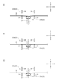
次に、ステップS2において、旧糸2bの捻り目4を形成する。具体的には、図9(b)に示すように、糸ガイド23が旋回することによって、旧糸2bのフック22よりも下流側の部分を前方へ連行する。これにより、編針21の前方に、旧糸2bの屈曲された部分が形成される。以下、旧糸2bの屈曲された部分を、バッファ3と称する。バッファ3は、下側フック22bの下方から編針21の前方に延びた後、再び下方の第三糸押え26側に延びるように屈曲する。Next, in step S2, a twist 4 is formed in the old yarn 2b. Specifically, as shown in FIG. 9(b), the yarn guide 23 rotates to bring the portion of the old yarn 2b downstream of the hook 22 forward. This forms a bent portion of the old yarn 2b in front of the knitting needle 21. Hereinafter, the bent portion of the old yarn 2b is referred to as the buffer 3. The buffer 3 extends from below the lower hook 22b to the front of the knitting needle 21, and then bends again to extend downward toward the third yarn presser 26.

次に、フック22が右方に移動して旧糸2bをさらに右方に引き込む。次に、図9(c)に示すように、編針21が、前方に移動して上側フック22aと下側フック22bとの間に進入する。フック22が左方に移動した後、図10(a)に示すように、編針21が、後方へ移動して上側フック22aと下側フック22bとの間から退出することにより、旧糸2bを引っ掛け、後方へ連行する。次に、図10(b)に示すように、編針21が半回転することによって、旧糸2bが捻られてループ状の捻り目4が形成される。Next, the hook 22 moves to the right and pulls the old yarn 2b further to the right. Next, as shown in FIG. 9(c), the knitting needle 21 moves forward and enters between the upper hook 22a and the lower hook 22b. After the hook 22 moves to the left, as shown in FIG. 10(a), the knitting needle 21 moves rearward and exits between the upper hook 22a and the lower hook 22b, thereby hooking the old yarn 2b and dragging it rearward. Next, as shown in FIG. 10(b), the knitting needle 21 rotates half a turn, twisting the old yarn 2b and forming a loop-shaped twist 4.

次に、ステップS3において、旧糸2bの編目5を形成する。具体的には、図10(c)に示すように、編針21が、前方に移動して、引掛部21aが旧糸2bのバッファ3の部分を引っ掛ける。次に、図11(a)に示すように、編針21が、後方へ移動して上側フック22aと下側フック22bとの間から退出し、旧糸2bを捻り目4に通すことにより、編目5を形成する。このとき、旧糸2bは、最初は下側フック22bの本体部28に巻きついているが、フック22が少し右方に移動すること、及び編針21が旧糸2bを後方へ引き込むことにより、図11(b)に示すように、旧糸2bは、下側フック22bの引掛部29に巻きついた状態となる。Next, in step S3, the stitch 5 of the old yarn 2b is formed. Specifically, as shown in FIG. 10(c), the knitting needle 21 moves forward, and the hook portion 21a hooks the buffer 3 portion of the old yarn 2b. Next, as shown in FIG. 11(a), the knitting needle 21 moves backward and exits between the upper hook 22a and the lower hook 22b, and the old yarn 2b is passed through the twisted stitch 4 to form the stitch 5. At this time, the old yarn 2b is initially wound around the main body portion 28 of the lower hook 22b, but as the hook 22 moves slightly to the right and the knitting needle 21 pulls the old yarn 2b backward, the old yarn 2b is wound around the hook portion 29 of the lower hook 22b as shown in FIG. 11(b).

その後、糸ガイド23が、図5(b)に示す矢印と反対方向へ旋回して元の位置に戻る。さらに、第二糸押え25が、押え位置に変位することにより、旧糸2bのフック22よりも上流側の部分を押える。After that, the yarn guide 23 rotates in the direction opposite to the arrow shown in Figure 5 (b) and returns to its original position. Furthermore, the second yarn presser 25 is displaced to the presser position, thereby pressing down the portion of the old yarn 2b upstream of the hook 22.

次に、ステップS4において、編目5に新糸2aを引き込む。具体的には、図12(a)に示すように、編針21が前方へ移動した後、図3(a)及び図3(b)に示すように糸選択部10の糸案内レバー14が回動することにより、新糸2aがフック22の前方に連行される。次に、図12(b)に示すように、編針21が、引掛部21aにおいて新糸2aを引っ掛けた状態で後方へ移動することにより、新糸2aを編目5に通す。そして、糸案内レバー14は、図2(a)に示す元の位置に戻る。Next, in step S4, the new yarn 2a is drawn into the stitch 5. Specifically, as shown in Fig. 12(a), the knitting needle 21 moves forward, and then the yarn guide lever 14 of the yarn selection unit 10 rotates as shown in Figs. 3(a) and 3(b), thereby bringing the new yarn 2a forward of the hook 22. Next, as shown in Fig. 12(b), the knitting needle 21 moves backward with the new yarn 2a hooked at the hook portion 21a, thereby passing the new yarn 2a through the stitch 5. Then, the yarn guide lever 14 returns to its original position as shown in Fig. 2(a).

次に、ステップS5において、フック22への旧糸2bの巻きつけを解消する。具体的には、図8(b)に示すように、フック22が左方へ移動することにより、旧糸2bの巻きつけられた部分が下側フック22bから外れる。Next, in step S5, the old thread 2b is unwound from the hook 22. Specifically, as shown in FIG. 8(b), the hook 22 moves to the left, causing the wound portion of the old thread 2b to come off the lower hook 22b.

次に、ステップS6において、旧糸2b及び新糸2aに張力を付与する。具体的には、カッター24が、切断位置に変位することにより、図13(a)に示すように新糸2a及び旧糸2bのフック22よりも上方の部分を切断し、切断後に退避位置に変位する。次に、編針21が、後方へ移動して、引掛部21aに引っ掛けた新糸2aを後方へ引っ張り込むことにより、新糸2aの切断後の端部を編目5側へ引っ張る。編針21が、さらに後方へ移動することにより、図13(b)に示すように、新糸2aの切断後の端部が編目5を後側に通ると共に、新糸2aが編針21の引掛部21aから外れる。Next, in step S6, tension is applied to the old yarn 2b and the new yarn 2a. Specifically, the cutter 24 is displaced to the cutting position, and cuts the parts of the new yarn 2a and the old yarn 2b above the hook 22 as shown in FIG. 13(a), and displaces to the retreated position after cutting. Next, the knitting needle 21 moves rearward and pulls the new yarn 2a hooked on the hook portion 21a rearward, thereby pulling the cut end of the new yarn 2a toward the stitch 5. The knitting needle 21 moves further rearward, and as shown in FIG. 13(b), the cut end of the new yarn 2a passes through the stitch 5 to the rear, and the new yarn 2a is released from the hook portion 21a of the knitting needle 21.

次に、旧糸2bのフック22よりも上流側の部分が第二糸押え25によって押えられた状態で、テンショナー27による張力によって旧糸2bが下流側へ引っ張られる。これにより、図14(a)に示すように、編目5及び編目5に通された新糸2aが捻り目4を通って捻り目4の前側まで引き出される。次に、第三糸押え26が、押え位置に変位することにより、旧糸2bのフック22よりも下流側の部分を押える。そして、図5(b)に示すように糸ガイド23が回転して旧糸2bを引っ掛けることによって、図14(b)に示すように、結び目が締まる方向に旧糸2b及び新糸2aに張力が付与される。さらに、第三糸押え26が退避位置に変位して、旧糸2bにテンショナー27等による張力が付与されることにより、はた結びが完成し、旧糸2bと新糸2aとが糸継ぎされる。Next, while the part of the old thread 2b upstream of the hook 22 is held down by the second thread holder 25, the old thread 2b is pulled downstream by the tension of the tensioner 27. As a result, as shown in FIG. 14(a), the stitch 5 and the new thread 2a threaded through the stitch 5 are pulled out to the front of the twisted loop 4 through the twisted loop 4. Next, the third thread holder 26 is displaced to the holding position to hold down the part of the old thread 2b downstream of the hook 22. Then, as shown in FIG. 5(b), the thread guide 23 rotates to hook the old thread 2b, and tension is applied to the old thread 2b and the new thread 2a in the direction of tightening the knot, as shown in FIG. 14(b). Furthermore, the third thread holder 26 is displaced to the retracted position, and tension is applied to the old thread 2b by the tensioner 27, etc., completing the knot, and the old thread 2b and the new thread 2a are spliced.

以上のように、本実施形態に係るノッター装置1においては、旧糸2bと新糸2aとをはた結びすることによって、固結びする場合と比べて結び目を小さくできるため、編機における編成時の抵抗を低減することができる。また、糸端部の繊維を解撚しながら交絡させることで接続するスプライサーとは異なり、旧糸2bの色と新糸2aの色とが互いに異なる場合であっても、糸の継ぎ目が滲むのを抑制することができる。As described above, in the knotter device 1 according to this embodiment, by tying the old yarn 2b and the new yarn 2a together, the knot can be made smaller than when it is tightly knotted, and therefore the resistance during knitting in the knitting machine can be reduced. Also, unlike a splicer that connects the yarn ends by untwisting and intertwining the fibers, it is possible to prevent the yarn joint from bleeding even when the colors of the old yarn 2b and the new yarn 2a are different from each other.

なお、新糸2aが弾性糸等の伸縮性を備える糸である場合は、図12(b)から図14(a)に二点鎖線の円で示す新糸2aの位置(例えば、編目5と糸案内レバー14の先端14aとの間、且つ編目5の近傍の位置)を、図示しない他の押え部材で押えながら、カッター24による切断及び編針21による新糸2aの引っ張りを行う。これにより、カッター24で新糸2aを切断したときに、結び目から、張力の高まりが解放された新糸2aが抜けてしまうのを抑制することができる。また、押え部材による押えは、糸ガイド23による結び目の締め付けを経てから解放される。 When the new yarn 2a is an elastic yarn or other stretchable yarn, the position of the new yarn 2a shown by the two-dot chain circle in Figures 12(b) to 14(a) (for example, a position between the stitch 5 and the tip 14a of the yarn guide lever 14, and in the vicinity of the stitch 5) is held down by another holding member (not shown) while the cutter 24 cuts the new yarn 2a and the knitting needle 21 pulls the new yarn 2a. This makes it possible to prevent the new yarn 2a, whose tension has been released, from coming out of the knot when the new yarn 2a is cut by the cutter 24. The holding down by the holding member is released after the knot has been tightened by the yarn guide 23.

本実施形態に係るノッター装置1において、糸選択部10及び糸継ぎ部20の各構成部材は、機械的に連動して動作するわけではなく、個別に動作する。このため、糸選択部10及び糸継ぎ部20の各構成部材の動作のタイミングは、制御部30によって個別に制御可能である。In the knotter device 1 according to this embodiment, the components of the thread selection unit 10 and the thread splicing unit 20 do not operate in a mechanically linked manner, but operate individually. Therefore, the timing of the operation of each component of the thread selection unit 10 and the thread splicing unit 20 can be individually controlled by the control unit 30.

このため、旧糸2b及び新糸2aの切れ易さや表面の摩擦度合いに応じて、フック22の旧糸2bへの巻きつけの解消、及び、テンショナー27及び糸案内レバー14による旧糸2bへの張力の増加の相対的なタイミングを任意に設定することができる。Therefore, depending on the breakability of the old thread 2b and the new thread 2a and the degree of surface friction, the relative timing of the unwinding of the hook 22 from the old thread 2b and the increase in tension on the old thread 2b by the tensioner 27 and the thread guide lever 14 can be set arbitrarily.

例えば、旧糸2b及び新糸2aの表面が比較的滑りの悪いものである場合、新糸2aを通した編目5が捻り目4を後側に上手く通り抜けることができずに、結び目が上手く形成できない場合がある。これを防止するために、下側フック22bへの旧糸2bの巻きつきを解消するタイミングを遅らせてもよい。例えば、旧糸2b及び新糸2aに張力を付与している間も、しばらく下側フック22bに旧糸2bを巻きつけた状態としてもよい。これにより、新糸2aを通した編目5を捻り目4の前側に引き出している間も、捻り目4のサイズを大きい状態で維持することができるので、新糸2aを通した編目5を捻り目4を通り易くすることができる。For example, if the surfaces of the old thread 2b and the new thread 2a are relatively slippery, the stitch 5 through which the new thread 2a is passed may not be able to pass through the twisted loop 4 to the rear side, and the knot may not be formed properly. To prevent this, the timing of unwinding the old thread 2b around the lower hook 22b may be delayed. For example, the old thread 2b may be left wound around the lower hook 22b for a while while tension is being applied to the old thread 2b and the new thread 2a. This allows the size of the twisted loop 4 to be maintained large even while the stitch 5 through which the new thread 2a is passed is being pulled out to the front side of the twisted loop 4, making it easier for the stitch 5 through which the new thread 2a is passed to pass through the twisted loop 4.

一方、旧糸2b及び新糸2aの表面が比較的滑りの良いものである場合、新糸2aを通した編目5が捻り目4の前側に引っ張られすぎて、捻り目4が裏返り新糸2aが旧糸2bに絡まる場合がある。これを防止するために、下側フック22bへの旧糸2bの巻きつきを解消するタイミングを早めてもよい。例えば、図12(a)と図12(b)との間、すなわち編目5に新糸2aを引き込む前に、下側フック22bへの旧糸2bの巻きつきを解消してもよい。これにより、捻り目4のサイズが小さくなるので、新糸2aを通した編目5が捻り目4の後側に引っ張られすぎるのを抑制できる。On the other hand, if the surfaces of the old yarn 2b and the new yarn 2a are relatively smooth, the stitch 5 through which the new yarn 2a is passed may be pulled too far toward the front of the twisted loop 4, causing the twisted loop 4 to turn inside out and the new yarn 2a to become entangled with the old yarn 2b. To prevent this, the timing for unwinding the old yarn 2b around the lower hook 22b may be accelerated. For example, the old yarn 2b may be unwound around the lower hook 22b between Figures 12(a) and 12(b), that is, before the new yarn 2a is pulled into the stitch 5. This reduces the size of the twisted loop 4, preventing the stitch 5 through which the new yarn 2a is passed from being pulled too far toward the rear of the twisted loop 4.

このように、テンショナー27及び糸ガイド23による旧糸2bへの張力の増加に対する、フック22の旧糸2bへの巻きつけの解消のタイミングを任意に設定することができる。したがって、糸切れや糸結びの不良の発生を抑制することができる。In this way, the timing for unwinding the hook 22 from the old thread 2b in response to an increase in tension on the old thread 2b by the tensioner 27 and the thread guide 23 can be set as desired. This makes it possible to prevent thread breakage and poor thread knotting.

以上、本発明の実施形態について説明したが、本発明は上記実施形態に限定されるものではなく、特許請求の範囲に記載された発明の技術的思想の範囲内で適宜の変更が可能である。 The above describes an embodiment of the present invention, but the present invention is not limited to the above embodiment and may be modified as appropriate within the scope of the technical idea of the invention described in the claims.

例えば、本実施形態においては、編針21は、捻り目4を一重に形成するものとしたが、多重に形成するものとしてもよい。以下、捻り目4を多重に形成する方法について説明する。For example, in this embodiment, the knitting needle 21 is configured to form a single twist 4, but it may be configured to form multiple twists. A method for forming multiple twists 4 will be described below.

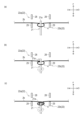
図15(a)に示すように、編針21が半回転することによって、旧糸2bが捻られてループ状の捻り目4が形成される。次に、図15(b)に示すように、編針21が、べらが捻り目4を抜けない範囲で前方に移動して、上側フック22aと下側フック22bとの間に進入する。As shown in Fig. 15(a), the knitting needle 21 rotates half a turn, twisting the old yarn 2b and forming a loop-shaped twist 4. Next, as shown in Fig. 15(b), the knitting needle 21 moves forward without the latch passing through the twist 4, and enters between the upper hook 22a and the lower hook 22b.

次に、図15(c)に示すように、編針21が、上側フック22aと下側フック22bとの間に進入した状態で半回転する。次に、図16(a)に示すように、編針21が、後方へ移動する。Next, as shown in Fig. 15(c), the knitting needle 21 rotates half a turn while being inserted between the upper hook 22a and the lower hook 22b. Next, as shown in Fig. 16(a), the knitting needle 21 moves backward.

次に、図16(b)に示すように、編針21が、これまでと同じ方向に回転する。編針21が、回転途中で、引掛部21aにおいて旧糸2bを引っ掛ける。編針21が、図16(a)に示す状態から半回転することにより、図16(c)に示すように、編針21に対して旧糸2bが2回巻きついた状態となる。これにより、捻り目4を二重に形成することができる。Next, as shown in Fig. 16(b), the knitting needle 21 rotates in the same direction as before. As the knitting needle 21 rotates, it hooks the old yarn 2b at the hook portion 21a. As the knitting needle 21 rotates half a turn from the state shown in Fig. 16(a), the old yarn 2b is wound twice around the knitting needle 21, as shown in Fig. 16(c). This allows the twist stitch 4 to be formed twice.

これにより、旧糸2bと新糸2aとの結び目をより外れ難くすることができる。なお、図15及び図16に示す工程を繰り返すことにより、捻り目4を三重以上に形成することも可能である。This makes it harder for the knot between the old thread 2b and the new thread 2a to come undone. It is also possible to form three or more twists 4 by repeating the steps shown in Figures 15 and 16.

本発明は、糸選択部及び糸継ぎ部を具備するノッター装置に適用することができる。 The present invention can be applied to a knotter device having a thread selection unit and a thread splicing unit.

1 ノッター装置
10 糸選択部
14 糸案内レバー
20 糸継ぎ部
21 編針
22 フック
23 糸ガイド
24 カッター
25 第二糸押え
26 第三糸押え
27 テンショナー
REFERENCE SIGNS LIST 1 knotter device 10 yarn selection section 14 yarn guide lever 20 yarn splicing section 21 knitting needle 22 hook 23 yarn guide 24 cutter 25 second yarn presser 26 third yarn presser 27 tensioner

Claims (8)

糸選択部及び糸継ぎ部を具備するノッター装置であって、
前記糸選択部は、
糸源から供給される新糸を前記糸継ぎ部へ案内する案内レバーを有し、
前記糸継ぎ部は、
旧糸を延伸方向とは異なる方向へ案内可能な案内部と、
前記旧糸を引っ掛けると共に捻って捻り目を形成し、前記案内部により案内された前記旧糸の他の部分を引っ掛けて前記捻り目を一側に通して編目を形成し、前記案内レバーにより案内された前記新糸を前記編目に通す編針と、
前記編針が前記編目を形成する際に前記旧糸が巻きつけられると共に、巻きつけを解消するように動作可能なフック部と、
前記新糸を通した前記編目が前記捻り目を他側に通るように前記旧糸の張力を増加させる張力付与部と、を有する、
ノッター装置。
A knotter device having a thread selection unit and a thread splicing unit,
The yarn selection unit includes:
a guide lever for guiding a new yarn supplied from a yarn source to the yarn splicing section;
The yarn splicing unit includes:
a guide section capable of guiding the old yarn in a direction different from the drawing direction;
a knitting needle that hooks and twists the old yarn to form a twisted stitch, hooks another part of the old yarn guided by the guide portion and passes the twisted stitch to one side to form a stitch, and passes the new yarn guided by the guide lever through the stitch;
a hook portion around which the old yarn is wound when the knitting needle forms the stitch, and which is operable to release the winding;
and a tension applying section that increases the tension of the old yarn so that the stitch through which the new yarn is passed passes through the twisted loop on the other side.
Knotter device.
前記フック部の前記旧糸への巻きつけの解消、及び、前記張力付与部による前記旧糸への張力の増加の相対的なタイミングを任意に設定可能である、
請求項1に記載のノッター装置。
The relative timing of unwinding the hook portion from the old yarn and increasing the tension on the old yarn by the tension applying unit can be set arbitrarily.
The knotter device according to claim 1 .
前記フック部は、前記旧糸との巻きつけを解消するタイミングを任意に変更可能に構成される、
請求項1又は請求項2に記載のノッター装置。
The hook portion is configured to be able to arbitrarily change the timing at which it is released from the winding of the old yarn.
The knotter device according to claim 1 or 2.
前記フック部は、前記旧糸が配置可能な一対のフック状部材を有し、
前記編針は、前記一対のフック状部材の間に進退可能かつ軸線回りに回転可能に構成される、
請求項1から請求項3までのいずれか一項に記載のノッター装置。
The hook portion has a pair of hook-shaped members on which the old thread can be placed,
The knitting needle is configured to be movable between the pair of hook-shaped members and rotatable around an axis.
A knotter device according to any one of claims 1 to 3.
前記案内部は、前記旧糸の前記フック部よりも下流側の部分を、前記フック部を介して前記編針と対向する位置に案内する、
請求項1から請求項4までのいずれか一項に記載のノッター装置。
The guide portion guides a portion of the old yarn downstream of the hook portion to a position facing the knitting needle via the hook portion.
A knotter device according to any one of claims 1 to 4.
前記新糸が前記編目に通された後、前記編目よりも上流側において前記旧糸を保持可能な保持部と、
前記保持部により前記旧糸が保持された状態で、前記新糸及び前記旧糸の不要部分を切断する切断部と、
を具備し、
前記張力付与部は、
前記切断部による切断後に前記旧糸の張力を増加させる、
請求項1から請求項5までのいずれか一項に記載のノッター装置。
a holding portion capable of holding the old yarn on an upstream side of the stitch after the new yarn is passed through the stitch;
a cutting unit that cuts off unnecessary portions of the new yarn and the old yarn while the old yarn is held by the holding unit;
Equipped with
The tension applying portion is
increasing the tension of the old yarn after the cutting by the cutting section;
A knotter device according to any one of claims 1 to 5.
前記張力付与部は、前記案内部を含む、
請求項1から請求項6までのいずれか一項に記載のノッター装置。
The tension applying portion includes the guide portion.
A knotter device according to any one of claims 1 to 6.
前記編針は、前記捻り目を多重に形成する、
請求項1から請求項7までのいずれか一項に記載のノッター装置。
The knitting needle forms the twisted stitches in multiple layers.
A knotter device according to any one of claims 1 to 7.
JP2024511460A 2022-03-28 2023-02-22 Knotter device Active JP7607828B2 (en)

Applications Claiming Priority (3)

Application Number Priority Date Filing Date Title
JP2022052496 2022-03-28
PCT/JP2023/006520 WO2023189041A1 (en) 2022-03-28 2023-02-22 Knotter device

Publications (2)

Publication Number Publication Date
JPWO2023189041A1 JPWO2023189041A1 (en) 2023-10-05
JP7607828B2 true JP7607828B2 (en) 2024-12-27

Family

ID=88200537

Family Applications (1)

Application Number Title Priority Date Filing Date
JP2024511460A Active JP7607828B2 (en) 2022-03-28 2023-02-22 Knotter device

Country Status (5)

Country Link
EP (1) EP4501831A1 (en)
JP (1) JP7607828B2 (en)
KR (1) KR20240165447A (en)
CN (1) CN118922364A (en)
WO (1) WO2023189041A1 (en)

Citations (1)

* Cited by examiner, † Cited by third party
Publication number Priority date Publication date Assignee Title
JP2007106548A (en) 2005-10-13 2007-04-26 Shima Seiki Mfg Ltd Splicer device

Family Cites Families (2)

* Cited by examiner, † Cited by third party
Publication number Priority date Publication date Assignee Title
JPH081254Y2 (en) * 1991-11-14 1996-01-17 ジューキ株式会社 Knotting device
JP2002035460A (en) 2000-07-28 2002-02-05 Brother Ind Ltd Yarn knotting method and apparatus

Patent Citations (1)

* Cited by examiner, † Cited by third party
Publication number Priority date Publication date Assignee Title
JP2007106548A (en) 2005-10-13 2007-04-26 Shima Seiki Mfg Ltd Splicer device

Also Published As

Publication number Publication date
KR20240165447A (en) 2024-11-22
WO2023189041A1 (en) 2023-10-05
EP4501831A1 (en) 2025-02-05
CN118922364A (en) 2024-11-08
JPWO2023189041A1 (en) 2023-10-05

Similar Documents

Publication Publication Date Title
JP4082930B2 (en) Yarn twisting device
KR101476951B1 (en) Method for preventing stitch from coming apart, device for preventing stitch from coming apart, and stitch structure
JP4110415B2 (en) Yarn splicer and handy splicer
CN101501255B (en) Yarn splicing method, yarn splicing device and products obtained therefor
GB2066315A (en) Spliced joints of spun yarn
JP7607828B2 (en) Knotter device
JP4677454B2 (en) Yarn splicing method and apparatus
JP2004027463A (en) Method for piercing spun yarn, devicefor the same and pierced up section
JP4559337B2 (en) Splicer equipment
US3892432A (en) Continuous yarn drawing method and apparatus
JP2002035460A (en) Yarn knotting method and apparatus
IT8349503A1 (en) METHOD AND APPARATUS FOR JOINING TEXTILE THREADS.
JPH11106147A (en) Multisplicer
JPH09176942A (en) Treating system for yarn
JP2022161459A (en) Yarn splicing nozzle and winding device
JPH03236897A (en) Device for threading needle in necktie sewing machine
JP2005143950A (en) Eyelet hole sewing machine
JPH0545698B2 (en)
JP2002035461A (en) Tying device
JP7309679B2 (en) rope tying device
JP2002046942A (en) Tying device
CN118531572A (en) Embroidery machine thread changing mechanism
JPH01213421A (en) Ending of twisted yarn and device therefor
JP2022113421A (en) Yarn winding device
JPH01124659A (en) Method for repairing cut warp yarn of loom

Legal Events

Date Code Title Description
A621 Written request for application examination

Free format text: JAPANESE INTERMEDIATE CODE: A621

Effective date: 20240716

TRDD Decision of grant or rejection written
A01 Written decision to grant a patent or to grant a registration (utility model)

Free format text: JAPANESE INTERMEDIATE CODE: A01

Effective date: 20241203

A61 First payment of annual fees (during grant procedure)

Free format text: JAPANESE INTERMEDIATE CODE: A61

Effective date: 20241217

R150 Certificate of patent or registration of utility model

Ref document number: 7607828

Country of ref document: JP

Free format text: JAPANESE INTERMEDIATE CODE: R150