JP7599080B2 - Optical transmitting device, optical receiving device, optical communication device, optical communication system, and control method thereof - Google Patents
Optical transmitting device, optical receiving device, optical communication device, optical communication system, and control method thereof Download PDFInfo
- Publication number
- JP7599080B2 JP7599080B2 JP2023075036A JP2023075036A JP7599080B2 JP 7599080 B2 JP7599080 B2 JP 7599080B2 JP 2023075036 A JP2023075036 A JP 2023075036A JP 2023075036 A JP2023075036 A JP 2023075036A JP 7599080 B2 JP7599080 B2 JP 7599080B2
- Authority
- JP
- Japan
- Prior art keywords
- optical
- subcarrier
- optical communication
- transmission
- receiving
- Prior art date
- Legal status (The legal status is an assumption and is not a legal conclusion. Google has not performed a legal analysis and makes no representation as to the accuracy of the status listed.)
- Active
Links
- 230000003287 optical effect Effects 0.000 title claims description 1036
- 238000004891 communication Methods 0.000 title claims description 361
- 238000000034 method Methods 0.000 title claims description 52
- 230000005540 biological transmission Effects 0.000 claims description 492
- 238000012545 processing Methods 0.000 claims description 18
- 230000000694 effects Effects 0.000 claims description 13
- 238000010586 diagram Methods 0.000 description 45
- 238000005516 engineering process Methods 0.000 description 20
- 239000013307 optical fiber Substances 0.000 description 18
- 238000013468 resource allocation Methods 0.000 description 18
- 230000010287 polarization Effects 0.000 description 10
- 238000006243 chemical reaction Methods 0.000 description 9
- 230000010355 oscillation Effects 0.000 description 8
- 238000001514 detection method Methods 0.000 description 7
- 239000011159 matrix material Substances 0.000 description 7
- 230000007423 decrease Effects 0.000 description 6
- 238000012544 monitoring process Methods 0.000 description 5
- 230000003247 decreasing effect Effects 0.000 description 4
- 230000010363 phase shift Effects 0.000 description 4
- 230000000052 comparative effect Effects 0.000 description 3
- 230000015654 memory Effects 0.000 description 3
- 230000004044 response Effects 0.000 description 3
- 101100521334 Mus musculus Prom1 gene Proteins 0.000 description 2
- 230000015556 catabolic process Effects 0.000 description 2
- 238000006731 degradation reaction Methods 0.000 description 2
- 230000002250 progressing effect Effects 0.000 description 2
- 238000004590 computer program Methods 0.000 description 1
- 239000002360 explosive Substances 0.000 description 1
- 230000002452 interceptive effect Effects 0.000 description 1
- 238000012423 maintenance Methods 0.000 description 1
- 238000007726 management method Methods 0.000 description 1
- 238000012986 modification Methods 0.000 description 1
- 230000004048 modification Effects 0.000 description 1
- 239000004065 semiconductor Substances 0.000 description 1
- 239000002699 waste material Substances 0.000 description 1
Images


Landscapes
- Optical Communication System (AREA)
Description
本発明は光送信装置、光受信装置、光通信装置、光通信システム、及びこれらの制御方法に関する。 The present invention relates to an optical transmitting device, an optical receiving device, an optical communication device, an optical communication system, and a control method thereof.
インターネットや映像配信等の広帯域マルチメディア通信サービスの爆発的な需要増加に伴い、幹線系やメトロ系ではより長距離大容量かつ高信頼な高密度波長多重光ファイバ通信システムの導入が進んでいる。また、加入者系においても、光ファイバアクセスサービスの普及が急速に進んでいる。こうした光ファイバを使用した通信システムでは、光伝送路である光ファイバの敷設コスト低減や、光ファイバ1本当たりの伝送帯域利用効率を高めることが重要である。このため、複数の異なる波長の光信号を多重化して伝送する、波長分割多重通信(WDM:Wavelength Division Multiplex)が広く用いられている。WDM技術では、1チャネルに対して1波長を使用していた。一方、最近ではWDM1チャネルの帯域あたり100Gbpsを超える伝送容量を実現可能なスーパーチャネル(SuperChannel)技術が注目を集めている。このスーパーチャネル技術では、1チャネルの帯域に対して複数の波長(サブキャリア)を使用しているため、波長を高密度に多重することができる。よって、今後、更に400Gbps、1Tbpsと伝送容量を大容量にするにあたり、このスーパーチャネル技術が重要となってくる。 With the explosive increase in demand for broadband multimedia communication services such as the Internet and video distribution, the introduction of long-distance, high-capacity, and highly reliable high-density wavelength multiplexing optical fiber communication systems is progressing in trunk and metro systems. In addition, the spread of optical fiber access services is also rapidly progressing in subscriber systems. In such communication systems using optical fibers, it is important to reduce the laying cost of optical fibers, which are optical transmission paths, and to increase the transmission bandwidth utilization efficiency per optical fiber. For this reason, wavelength division multiplexing (WDM), which multiplexes and transmits optical signals of multiple different wavelengths, is widely used. In WDM technology, one wavelength is used for one channel. On the other hand, recently, superchannel technology, which can achieve a transmission capacity of more than 100 Gbps per WDM channel band, has attracted attention. In this superchannel technology, multiple wavelengths (subcarriers) are used for the band of one channel, so wavelengths can be multiplexed at a high density. Therefore, this superchannel technology will become important in the future as transmission capacity is further increased to 400 Gbps and 1 Tbps.
特許文献1及び特許文献2には、WDMを用いた光通信に関する技術が開示されている。特許文献1には、効率的なネットワークの運用、管理及び保守を行うことができる光ネットワーク装置に関する技術が開示されている。特許文献2には、複数のサブキャリアを含む電気信号を、アナログ光変調により伝送する場合において、相互混合ノイズによる影響を低減できる光伝送装置に関する技術が開示されている。
通信ネットワークにおいては、所定のノード間におけるトラフィックには緩急がある。このため、所定のノード間における伝送は、常に最大伝送容量で行われる必要はない。一方、背景技術で説明したように、WDM技術を用いた光通信では、1チャネルに対して1波長を使用していた。このため、WDM技術を用いた光通信装置では、通信をオフにするか又は最大伝送容量で通信を行うかのいずれかしか選択肢がなく、伝送容量を中間の値に設定することはできなかった。 In a communication network, traffic between specific nodes fluctuates. For this reason, transmission between specific nodes does not always need to be performed at maximum transmission capacity. On the other hand, as explained in the background section, optical communications using WDM technology use one wavelength for one channel. For this reason, optical communications devices using WDM technology have no choice but to either turn off communications or communicate at maximum transmission capacity, and it is not possible to set the transmission capacity to an intermediate value.
これに対してスーパーチャネル技術を用いた場合は、WDMの1チャネルの帯域において複数の波長を用いているため、伝送容量を中間の値に設定することができる。この点を踏まえ、発明者は、伝送装置に対して1チャネルの帯域における複数の波長の内、一部を利用して伝送容量を中間の値にした場合、残りの波長を使用して他の伝送装置にリソースを配分できることを発見した。 In contrast, when super-channel technology is used, multiple wavelengths are used in the band of one WDM channel, so the transmission capacity can be set to an intermediate value. Based on this, the inventors have discovered that if the transmission capacity is set to an intermediate value by using some of the multiple wavelengths in the band of one channel for a transmission device, the remaining wavelengths can be used to allocate resources to other transmission devices.
上記に鑑み本発明の目的は、光通信ネットワークにおいて、効率的なリソース配分を実施できる光送信装置、光受信装置、光通信装置、光通信システム、及びこれらの制御方法を提供することである。 In view of the above, an object of the present invention is to provide an optical transmitting device, an optical receiving device, an optical communication device, an optical communication system, and a control method thereof that can perform efficient resource allocation in an optical communication network.
本発明にかかる光送信装置は、第1の光送信信号を送信する第1の送信部と、第2の光送信信号を送信する第2の送信部と、前記第1の光送信信号及び前記第2の光送信信号が一連の情報を共有する場合、前記第1の光送信信号及び前記第2の光送信信号の両方を第1の経路に出力し、前記第1の光送信信号及び前記第2の光送信信号が前記一連の情報を共有しない場合、前記第1の光送信信号及び前記第2の光送信信号のいずれか一方を第2の経路に出力する出力部と、を備える。 The optical transmission device according to the present invention includes a first transmission unit that transmits a first optical transmission signal, a second transmission unit that transmits a second optical transmission signal, and an output unit that outputs both the first optical transmission signal and the second optical transmission signal to a first path when the first optical transmission signal and the second optical transmission signal share a set of information, and outputs either the first optical transmission signal or the second optical transmission signal to a second path when the first optical transmission signal and the second optical transmission signal do not share the set of information.
本発明にかかる光受信装置は、サブキャリア受信信号を受信する第1及び第2の受信部と、入力された第1のサブキャリア受信信号及び第2のサブキャリア受信信号を前記第1及び第2の受信部に出力する切替部と、を備え、前記切替部は、前記第1及び第2のサブキャリア受信信号が一連の情報を共有する場合、前記第1及び第2のサブキャリア受信信号を同一の経路を経由して受信すると共に、前記第1のサブキャリア受信信号を前記第1の受信部に前記第2のサブキャリア受信信号を前記第2の受信部にそれぞれ出力し、前記第1のサブキャリア受信信号及び前記第2のサブキャリア受信信号が前記一連の情報を共有しない場合、前記第1及び第2のサブキャリア受信信号をそれぞれ異なる経路を経由して受信すると共に、前記第1のサブキャリア受信信号を前記第1の受信部に出力し、前記第2のサブキャリア受信信号を前記第2の受信部に出力する。 The optical receiving device according to the present invention comprises a first and a second receiving unit that receive a subcarrier reception signal, and a switching unit that outputs the input first subcarrier reception signal and the second subcarrier reception signal to the first and the second receiving units. When the first and the second subcarrier reception signals share a series of information, the switching unit receives the first and the second subcarrier reception signals via the same path and outputs the first subcarrier reception signal to the first receiving unit and the second subcarrier reception signal to the second receiving unit, respectively. When the first and the second subcarrier reception signals do not share the series of information, the switching unit receives the first and the second subcarrier reception signals via different paths, respectively, and outputs the first subcarrier reception signal to the first receiving unit and the second subcarrier reception signal to the second receiving unit.
本発明にかかる光通信装置は、第1の光送信信号を送信する第1の送信部と、第2の光送信信号を送信する第2の送信部と、前記第1の光送信信号及び前記第2の光送信信号が一連の情報を共有する場合、前記第1の光送信信号及び前記第2の光送信信号の両方を第1の経路に出力し、前記第1の光送信信号及び前記第2の光送信信号が前記一連の情報を共有しない場合、前記第1の光送信信号及び前記第2の光送信信号のいずれか一方を第2の経路に出力する出力部と、サブキャリア受信信号を受信する第1及び第2の受信部と、入力された第1のサブキャリア受信信号及び第2のサブキャリア受信信号を前記第1及び第2の受信部に出力する切替部と、を備え、前記切替部は、前記第1のサブキャリア受信信号及び前記第2のサブキャリア受信信号が一連の情報を共有する場合、前記第1のサブキャリア受信信号を前記第1の受信部に前記第2のサブキャリア受信信号を前記第2の受信部にそれぞれ出力し、前記第1のサブキャリア受信信号及び前記第2のサブキャリア受信信号が前記一連の情報を共有しない場合、前記第1のサブキャリア受信信号を前記2の受信部に出力する。 The optical communication device according to the present invention includes a first transmitting unit that transmits a first optical transmission signal, a second transmitting unit that transmits a second optical transmission signal, an output unit that outputs both the first optical transmission signal and the second optical transmission signal to a first path when the first optical transmission signal and the second optical transmission signal share a series of information, and outputs either the first optical transmission signal or the second optical transmission signal to a second path when the first optical transmission signal and the second optical transmission signal do not share the series of information, first and second receiving units that receive a subcarrier reception signal, and an input and a switching unit that outputs a first subcarrier reception signal and a second subcarrier reception signal to the first and second receiving units, and when the first subcarrier reception signal and the second subcarrier reception signal share a series of information, the switching unit outputs the first subcarrier reception signal to the first receiving unit and the second subcarrier reception signal to the second receiving unit, respectively, and when the first subcarrier reception signal and the second subcarrier reception signal do not share the series of information, the switching unit outputs the first subcarrier reception signal to the second receiving unit.
本発明にかかる光通信システムは、光送信装置と、第1及び第2の光受信装置と、を備える光通信システムであって、前記光送信装置は、第1の光送信信号を送信する第1の送信部と、第2の光送信信号を送信する第2の送信部と、前記第1の光送信信号及び前記第2の光送信信号が一連の情報を共有する場合、前記第1の光送信信号及び前記第2の光送信信号の両方を前記第1の光受信装置に出力し、前記第1の光送信信号及び前記第2の光送信信号が前記一連の情報を共有しない場合、前記第1の光送信信号及び前記第2の光送信信号のいずれか一方を前記第2の光受信装置に出力する出力部と、を備える。 The optical communication system according to the present invention is an optical communication system including an optical transmission device and first and second optical receiving devices, and the optical transmission device includes a first transmission unit that transmits a first optical transmission signal, a second transmission unit that transmits a second optical transmission signal, and an output unit that outputs both the first optical transmission signal and the second optical transmission signal to the first optical receiving device when the first optical transmission signal and the second optical transmission signal share a set of information, and outputs either the first optical transmission signal or the second optical transmission signal to the second optical receiving device when the first optical transmission signal and the second optical transmission signal do not share the set of information.
本発明にかかる光通信システムは、第1及び第2の光送信信号を送信する光送信装置と、前記第1及び第2の光送信信号を受信する第1及び第2の光受信装置と、前記光送信装置を制御するコントローラと、を備え、前記光送信装置は、前記コントローラからの指示に応じて、前記第1の光送信信号及び前記第1の光送信信号と一連の情報を共有する第2の光送信信号を前記第1の光受信装置に出力し、前記第1の光送信信号と一連の情報を共有しない第2の光送信信号を前記第2の光受信装置に出力する。 The optical communication system according to the present invention comprises an optical transmitting device that transmits first and second optical transmission signals, a first and second optical receiving device that receive the first and second optical transmission signals, and a controller that controls the optical transmitting device, and the optical transmitting device outputs the first optical transmission signal and a second optical transmission signal that shares a series of information with the first optical transmission signal to the first optical receiving device, and outputs a second optical transmission signal that does not share a series of information with the first optical transmission signal to the second optical receiving device, in response to an instruction from the controller.
本発明にかかる光通信システムは、第1及び第2の光送信装置と、光受信装置と、を備える光通信システムであって、前記光受信装置は、サブキャリア受信信号を受信する第1及び第2の受信部と、入力された第1のサブキャリア受信信号及び第2のサブキャリア受信信号を前記第1及び第2の受信部に出力する切替部と、を備え、前記切替部は、前記第1及び第2のサブキャリア受信信号が一連の情報を共有する場合、前記第1及び第2のサブキャリア受信信号を同一の光送信装置から受信すると共に、前記第1のサブキャリア受信信号を前記第1の受信部に前記第2のサブキャリア受信信号を前記第2の受信部にそれぞれ出力し、前記第1のサブキャリア受信信号及び前記第2のサブキャリア受信信号が前記一連の情報を共有しない場合、前記第1及び第2のサブキャリア受信信号をそれぞれ異なる光送信装置から受信すると共に、前記第1のサブキャリア受信信号を前記第1の受信部に出力し、前記第2のサブキャリア受信信号を前記第2の受信部に出力する。 The optical communication system according to the present invention is an optical communication system comprising a first and second optical transmission device and an optical reception device, the optical reception device comprising a first and second reception unit that receives a subcarrier reception signal, and a switching unit that outputs the input first subcarrier reception signal and second subcarrier reception signal to the first and second reception units, and when the first and second subcarrier reception signals share a series of information, the switching unit receives the first and second subcarrier reception signals from the same optical transmission device and outputs the first subcarrier reception signal to the first reception unit and the second subcarrier reception signal to the second reception unit, respectively, and when the first subcarrier reception signal and the second subcarrier reception signal do not share the series of information, the switching unit receives the first and second subcarrier reception signals from different optical transmission devices, outputs the first subcarrier reception signal to the first reception unit, and outputs the second subcarrier reception signal to the second reception unit.
本発明にかかるコントローラは、光送信装置と、第1及び第2の光受信装置と、を備える光通信システムにおいて、前記光送信装置に対し、第1の光送信信号及び前記第1の光送信信号と一連の情報を共有する第2の光送信信号を前記第1の光受信装置に出力させ、前記第1の光送信信号と一連の情報を共有しない第2の光送信信号を前記第2の光受信装置に出力させる。 In an optical communication system including an optical transmitting device and first and second optical receiving devices, the controller of the present invention causes the optical transmitting device to output a first optical transmission signal and a second optical transmission signal that shares a series of information with the first optical transmission signal to the first optical receiving device, and causes the controller to output a second optical transmission signal that does not share a series of information with the first optical transmission signal to the second optical receiving device.
本発明にかかる光通信システムの制御方法は、光送信装置と、第1及び第2の光受信装置と、を備える光通信システムの制御方法であって、前記光送信装置は、第1の光送信信号を送信する第1の送信部と、第2の光送信信号を送信する第2の送信部と、前記第1の光送信信号及び前記第2の光送信信号が一連の情報を共有する場合、前記第1の光送信信号及び前記第2の光送信信号の両方を前記第1の光受信装置に出力し、前記第1の光送信信号及び前記第2の光送信信号が前記一連の情報を共有しない場合、前記第1の光送信信号及び前記第2の光送信信号のいずれか一方を前記第2の光受信装置に出力する出力部と、を備え、前記光通信システムの通信状態に応じて前記光送信装置並びに前記第1及び第2の光受信装置をそれぞれ制御する。 The control method of the optical communication system according to the present invention is a control method of an optical communication system including an optical transmission device and first and second optical receiving devices, the optical transmission device including a first transmitting unit that transmits a first optical transmission signal, a second transmitting unit that transmits a second optical transmission signal, and an output unit that outputs both the first optical transmission signal and the second optical transmission signal to the first optical receiving device when the first optical transmission signal and the second optical transmission signal share a series of information, and outputs either the first optical transmission signal or the second optical transmission signal to the second optical receiving device when the first optical transmission signal and the second optical transmission signal do not share the series of information, and controls the optical transmission device and the first and second optical receiving devices according to the communication state of the optical communication system.
本発明にかかるプログラムは、光送信装置と、第1及び第2の光受信装置と、を備える光通信システムを制御するプログラムであって、前記光送信装置は、第1の光送信信号を送信する第1の送信部と、第2の光送信信号を送信する第2の送信部と、前記第1の光送信信号及び前記第2の光送信信号が一連の情報を共有する場合、前記第1の光送信信号及び前記第2の光送信信号の両方を前記第1の光受信装置に出力し、前記第1の光送信信号及び前記第2の光送信信号が前記一連の情報を共有しない場合、前記第1の光送信信号及び前記第2の光送信信号のいずれか一方を前記第2の光受信装置に出力する出力部と、を備え、前記光通信システムの通信状態に応じて前記光送信装置並びに前記第1及び第2の光受信装置をそれぞれ制御する処理をコンピュータに実行させるためのプログラムである。 The program according to the present invention is a program for controlling an optical communication system including an optical transmission device and first and second optical receiving devices, the optical transmission device including a first transmitting unit that transmits a first optical transmission signal, a second transmitting unit that transmits a second optical transmission signal, and an output unit that outputs both the first optical transmission signal and the second optical transmission signal to the first optical receiving device when the first optical transmission signal and the second optical transmission signal share a set of information, and outputs either the first optical transmission signal or the second optical transmission signal to the second optical receiving device when the first optical transmission signal and the second optical transmission signal do not share the set of information, and causes a computer to execute a process of controlling the optical transmission device and the first and second optical receiving devices according to the communication state of the optical communication system.
本発明にかかる光送信方法は、第1の光送信信号を生成し、第2の光送信信号を生成し、前記第1の光送信信号及び前記第2の光送信信号が一連の情報を共有する場合、前記第1の光送信信号及び前記第2の光送信信号の両方を第1の経路に出力し、前記第1の光送信信号及び前記第2の光送信信号が前記一連の情報を共有しない場合、前記第1の光送信信号及び前記第2の光送信信号のいずれか一方を第2の経路に出力する。 The optical transmission method according to the present invention generates a first optical transmission signal, generates a second optical transmission signal, and outputs both the first optical transmission signal and the second optical transmission signal to a first path if the first optical transmission signal and the second optical transmission signal share a set of information, and outputs either the first optical transmission signal or the second optical transmission signal to a second path if the first optical transmission signal and the second optical transmission signal do not share the set of information.
本発明にかかる光受信方法は、第1及び第2のサブキャリア受信信号が一連の情報を共有する場合、前記第1及び第2のサブキャリア受信信号を同一の経路を経由して受信すると共に、前記第1のサブキャリア受信信号を第1の受信部に前記第2のサブキャリア受信信号を第2の受信部にそれぞれ出力し、前記第1のサブキャリア受信信号及び前記第2のサブキャリア受信信号が前記一連の情報を共有しない場合、前記第1及び第2のサブキャリア受信信号をそれぞれ異なる経路を経由して受信すると共に、前記第1のサブキャリア受信信号を前記第1の受信部に出力し、前記第2のサブキャリア受信信号を前記第2の受信部に出力する。 In the optical receiving method according to the present invention, when the first and second subcarrier reception signals share a series of information, the first and second subcarrier reception signals are received via the same path, and the first subcarrier reception signal is output to the first receiving unit and the second subcarrier reception signal is output to the second receiving unit, respectively. When the first subcarrier reception signal and the second subcarrier reception signal do not share the series of information, the first and second subcarrier reception signals are received via different paths, and the first subcarrier reception signal is output to the first receiving unit and the second subcarrier reception signal is output to the second receiving unit.
本発明により、光通信ネットワークにおいて、効率的なリソース配分を実施できる光送信装置、光受信装置、光通信装置、光通信システム、及びこれらの制御方法を提供することができる。 The present invention provides an optical transmitting device, an optical receiving device, an optical communication device, an optical communication system, and a control method thereof that can perform efficient resource allocation in an optical communication network.
<実施の形態1>
以下、図面を参照して本発明の実施の形態について説明する。図1は、実施の形態1にかかる光送信装置1_1を示すブロック図である。図1に示すように、本実施の形態にかかる光送信装置1_1は、第1の送信部11_1、第2の送信部11_2、及び出力部12を備える。なお、以下では第1及び第2の送信部をサブキャリア送信部という場合もある。
<First embodiment>
Hereinafter, an embodiment of the present invention will be described with reference to the drawings. Fig. 1 is a block diagram showing an optical transmission device 1_1 according to the first embodiment. As shown in Fig. 1, the optical transmission device 1_1 according to the present embodiment includes a first transmission unit 11_1, a second transmission unit 11_2, and an
第1の送信部11_1は第1の光送信信号21_1を送信する。第2の送信部11_2は第2の光送信信号21_2を送信する。すなわち、第1の送信部11_1及び第2の送信部11_2の各々には送信データが供給され、第1の送信部11_1及び第2の送信部11_2は、送信データを送信するための第1の光送信信号21_1及び第2の光送信信号21_2をそれぞれ生成する。第1の光送信信号21_1及び第2の光送信信号21_2は、サブキャリアを用いて送信データを送信するための信号である。 The first transmitting unit 11_1 transmits a first optical transmission signal 21_1. The second transmitting unit 11_2 transmits a second optical transmission signal 21_2. That is, transmission data is supplied to each of the first transmitting unit 11_1 and the second transmitting unit 11_2, and the first transmitting unit 11_1 and the second transmitting unit 11_2 generate a first optical transmission signal 21_1 and a second optical transmission signal 21_2, respectively, for transmitting the transmission data. The first optical transmission signal 21_1 and the second optical transmission signal 21_2 are signals for transmitting the transmission data using a subcarrier.
本実施の形態にかかる光送信装置1_1は、複数の異なる波長の光信号を多重化して伝送するWDM技術を用いている。つまり、第1の送信部11_1及び第2の送信部11_2で生成される第1の光送信信号21_1及び第2の光送信信号21_2は異なる波長を有する。特に本実施の形態にかかる光送信装置では、WDMの1チャネルの帯域に対して複数の波長(サブキャリア)を割り当てるスーパーチャネル技術を用いることができる。このスーパーチャネル技術を用いることで、波長を高密度に多重することができ、伝送容量を大容量にすることができる。 The optical transmission device 1_1 according to this embodiment uses WDM technology to multiplex and transmit optical signals of multiple different wavelengths. That is, the first optical transmission signal 21_1 and the second optical transmission signal 21_2 generated by the first transmitting unit 11_1 and the second transmitting unit 11_2 have different wavelengths. In particular, the optical transmission device according to this embodiment can use super-channel technology to assign multiple wavelengths (subcarriers) to one channel band of WDM. By using this super-channel technology, wavelengths can be multiplexed at high density, and transmission capacity can be increased.
出力部12は、第1の光送信信号21_1及び第2の光送信信号21_2が一連の情報を共有する場合、第1の光送信信号21_1及び第2の光送信信号21_2の両方を同一の経路(例えば第1の経路26_1)に出力する。
When the first optical transmission signal 21_1 and the second optical transmission signal 21_2 share a series of information, the
一方、出力部12は、第1の光送信信号21_1及び第2の光送信信号21_2が一連の情報を共有しない場合、第1の光送信信号21_1及び第2の光送信信号21_2のいずれか一方を、第2の経路に出力する。例えば、出力部12は、第1の光送信信号21_1及び第2の光送信信号21_2が一連の情報を共有しない場合、第1の光送信信号21_1を第1の経路26_1に出力し、第2の光送信信号21_2を第2の経路26_2に出力してもよい。また、例えば、出力部12は、第1の光送信信号21_1及び第2の光送信信号21_2が一連の情報を共有しない場合、第1の光送信信号21_1を第2の経路26_2に出力し、第2の光送信信号21_2を第1の経路26_1に出力してもよい。換言すると、出力部12は、第1の光送信信号21_1及び第2の光送信信号21_2が一連の情報を共有しない場合、第1の光送信信号21_1及び第2の光送信信号21_2の各々を異なる経路に出力する。
On the other hand, when the first optical transmission signal 21_1 and the second optical transmission signal 21_2 do not share a series of information, the
ここで、第1の光送信信号21_1及び第2の光送信信号21_2が一連の情報を共有する場合とは、例えば、第1の送信部11_1及び第2の送信部11_2が第1の光送信信号21_1及び第2の光送信信号21_2を用いて所定の送信データを並列に送信する場合である。 Here, the first optical transmission signal 21_1 and the second optical transmission signal 21_2 share a series of information when, for example, the first transmitting unit 11_1 and the second transmitting unit 11_2 transmit predetermined transmission data in parallel using the first optical transmission signal 21_1 and the second optical transmission signal 21_2.
一方、第1の光送信信号21_1及び第2の光送信信号21_2が一連の情報を共有しない場合とは、例えば、第1の送信部11_1及び第2の送信部11_2が第1の光送信信号21_1及び第2の光送信信号21_2を用いて所定の送信データを独立に送信する場合である。つまり、第1の送信部11_1は第1の光送信信号21_1を用いて所定の第1の送信データを送信し、第2の送信部11_1は第2の光送信信号21_1を用いて所定の第2の送信データを送信する場合である。この場合は、第1の光送信信号21_1及び第2の光送信信号21_2がそれぞれ独立した送信データを含んでいるので、第1の光送信信号21_1及び第2の光送信信号21_2をそれぞれ別々の経路(第1の経路26_1、第2の経路26_2)に出力することができる。 On the other hand, a case where the first optical transmission signal 21_1 and the second optical transmission signal 21_2 do not share a series of information is, for example, a case where the first transmitting unit 11_1 and the second transmitting unit 11_2 independently transmit predetermined transmission data using the first optical transmission signal 21_1 and the second optical transmission signal 21_2. That is, the first transmitting unit 11_1 transmits predetermined first transmission data using the first optical transmission signal 21_1, and the second transmitting unit 11_1 transmits predetermined second transmission data using the second optical transmission signal 21_1. In this case, since the first optical transmission signal 21_1 and the second optical transmission signal 21_2 each contain independent transmission data, the first optical transmission signal 21_1 and the second optical transmission signal 21_2 can be output to separate paths (first path 26_1, second path 26_2).
ここで第1の経路26_1とは第1の光受信装置(不図示)と接続される経路であり、第2の経路26_2とは第2の光受信装置(不図示)と接続される経路である。 Here, the first path 26_1 is a path connected to a first optical receiving device (not shown), and the second path 26_2 is a path connected to a second optical receiving device (not shown).
このように、本実施の形態にかかる光送信装置1_1では、出力部12を用いて第1の光送信信号21_1及び第2の光送信信号21_2の出力先を切り替えている。よって、効率的なリソース配分を実施できる光送信装置を提供することができる。この理由について以下で詳細に説明する。
In this way, in the optical transmission device 1_1 according to the present embodiment, the output destination of the first optical transmission signal 21_1 and the second optical transmission signal 21_2 is switched using the
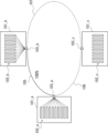
図2、図3は、比較例にかかる光通信システムを示す図であり、スーパーチャネル技術を用いた光通信システムの一例を示している。図2、図3に示す光通信システムは、光通信装置101_a~101_cを備える。光通信装置101_aは複数の送受信部102_aと単一の送受信ポート103_aとを備える。複数の送受信部102_aは各々異なる波長(サブキャリア)を用いて送受信可能に構成されている。つまり光通信装置101_aは、WDMの1チャネルの帯域に対して複数の波長(サブキャリア)を割り当てることができる。各々の送受信部102_aは各々のサブキャリアを用いて送受信可能に構成されている。光通信装置101_b、光通信装置101_cについても同様である。 Figures 2 and 3 show an optical communication system according to a comparative example, and show an example of an optical communication system using super channel technology. The optical communication system shown in Figures 2 and 3 includes optical communication devices 101_a to 101_c. The optical communication device 101_a includes multiple transceivers 102_a and a single transceiver port 103_a. The multiple transceivers 102_a are configured to be able to transmit and receive using different wavelengths (subcarriers). In other words, the optical communication device 101_a can assign multiple wavelengths (subcarriers) to one channel band of WDM. Each transceiver 102_a is configured to be able to transmit and receive using its own subcarrier. The same applies to the optical communication devices 101_b and 101_c.
図2、図3に示す光通信システムでは、光通信装置101_aと光通信装置101_bとが光ファイバ105を介して接続可能に構成されており、光通信装置101_aと光通信装置101_cとが光ファイバ106を介して接続可能に構成されており、光通信装置101_bと光通信装置101_cとが光ファイバ107を介して接続可能に構成されている。
In the optical communication system shown in Figures 2 and 3, the optical communication device 101_a and the optical communication device 101_b are configured to be connectable via
図2に示す例では、光通信装置101_aと光通信装置101_bとが光ファイバ105を介して接続されており、光通信装置101_aと光通信装置101_bとが最大伝送容量(100%)で通信を行っている場合を示している。
In the example shown in FIG. 2, optical communication device 101_a and optical communication device 101_b are connected via
通信ネットワークにおいては、所定のノード間におけるトラフィックには緩急がある。このため、光通信装置101_aと光通信装置101_bとの間における伝送は、常に最大伝送容量で行われる必要はない。背景技術で説明したように、WDM技術を用いた光通信では、1チャネルに対して1波長を使用していた。このため、WDM技術を用いた光通信装置では、通信をオフにするか又は最大伝送容量で通信を行うかのいずれかしか選択肢がなく、伝送容量を中間の値に設定することはできなかった。 In a communication network, traffic between certain nodes fluctuates. For this reason, transmission between optical communication device 101_a and optical communication device 101_b does not always need to be performed at the maximum transmission capacity. As explained in the background, in optical communication using WDM technology, one wavelength is used for one channel. For this reason, optical communication devices using WDM technology only have the option of either turning off communication or performing communication at the maximum transmission capacity, and it is not possible to set the transmission capacity to an intermediate value.
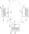
一方、スーパーチャネル技術を用いた場合は、WDMの1チャネルの帯域において複数の波長を用いているため、伝送容量を中間の値に設定することができる。このため、例えば図3に示すように、光通信装置101_aと光通信装置101_bとの間における伝送容量を最大伝送容量の50%に設定することができる。しかしこの場合は、光通信装置101_aの送受信部102_aのうち使用しない送受信部108_aが発生する。また、光通信装置101_bの送受信部102_bのうち使用しない送受信部108_bが発生する。 On the other hand, when super-channel technology is used, multiple wavelengths are used in the band of one WDM channel, so the transmission capacity can be set to an intermediate value. For this reason, for example, as shown in FIG. 3, the transmission capacity between optical communication device 101_a and optical communication device 101_b can be set to 50% of the maximum transmission capacity. However, in this case, unused transceiver unit 108_a will be generated among transceiver unit 102_a of optical communication device 101_a. Also, unused transceiver unit 108_b will be generated among transceiver unit 102_b of optical communication device 101_b.
スーパーチャネル技術を用いた場合は、各々の送受信部102_aにおいて送受信される信号は一連の情報を共有している。換言すると、各々の送受信部102_aはデータを並列に送受信している。このため、光通信装置101_aは単一のポート103_aを介して光信号を送受信するように構成されている。よって、光通信装置101_aの送受信部102_aのうち使用しない送受信部108_aが発生した場合であっても、使用しない送受信部108_aを他の光通信装置101_cとの通信に使用することができず、リソースが無駄になるという問題があった。 When super-channel technology is used, signals transmitted and received by each transceiver 102_a share a set of information. In other words, each transceiver 102_a transmits and receives data in parallel. For this reason, the optical communication device 101_a is configured to transmit and receive optical signals via a single port 103_a. Therefore, even if an unused transceiver 108_a occurs among the transceivers 102_a of the optical communication device 101_a, the unused transceiver 108_a cannot be used for communication with another optical communication device 101_c, resulting in a problem of wasted resources.
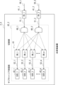
図4は本発明の効果を説明するための図である。なお、図4では光通信装置(送受信可能な光通信装置)を用いて本発明の効果について説明するが、本発明の効果は、光送信装置や光受信装置においても同様に得られることができる。 Figure 4 is a diagram for explaining the effects of the present invention. Note that in Figure 4, the effects of the present invention are explained using an optical communication device (an optical communication device capable of transmitting and receiving), but the effects of the present invention can be obtained in the same way in an optical transmitting device or an optical receiving device.
図4に示す光通信システムは、光通信装置110_a~110_cを備える。光通信装置110_aは、複数の送受信部111_a、切替部112_a、及び複数の送受信ポート113_1a、113_2aを備える。複数の送受信部111_aは各々異なるサブキャリアを用いて送受信可能に構成されている。つまり光通信装置110_aは、WDMの1チャネルの帯域において複数の波長(サブキャリア)を割り当てることができる。光通信装置110_b、光通信装置110_cについても同様である。 The optical communication system shown in FIG. 4 includes optical communication devices 110_a to 110_c. The optical communication device 110_a includes multiple transceivers 111_a, a switching unit 112_a, and multiple transceiver ports 113_1a and 113_2a. The multiple transceivers 111_a are each configured to be capable of transmitting and receiving using a different subcarrier. In other words, the optical communication device 110_a can allocate multiple wavelengths (subcarriers) in the band of one WDM channel. The same applies to the optical communication devices 110_b and 110_c.
このように光通信装置110_aは、複数の送受信ポート113_1a、113_2aを備えており、複数の送受信ポート113_1a、113_2aと接続される各々の送受信部111_aを切替部112_aを用いて切り替えることができる。よって、光通信装置110_aの複数の送受信部111_aの中に未使用の送受信部が発生した場合であっても、未使用の送受信部を他の光通信装置との通信に配分することができる。 In this way, the optical communication device 110_a has multiple transmission/reception ports 113_1a, 113_2a, and each of the transmission/reception units 111_a connected to the multiple transmission/reception ports 113_1a, 113_2a can be switched using the switching unit 112_a. Therefore, even if an unused transmission/reception unit occurs among the multiple transmission/reception units 111_a of the optical communication device 110_a, the unused transmission/reception unit can be allocated to communication with other optical communication devices.
例えば図3に示した光通信システムでは、光通信装置101_aと光通信装置101_bとの間における伝送容量を最大伝送容量の50%に設定に設定した場合は、光通信装置101_aの送受信部102_aのうち未使用の送受信部108_aが発生しリソースが無駄になっていた。これに対して図4に示した光通信システムでは、光通信装置111_aの未使用の送受信部(図3の送受信部108_aに対応)を切替部112_aを用いて送受信ポート113_2aと接続することで、未使用の送受信部を光通信装置110_cとの通信に配分することができる。よって、光通信ネットワークにおいて、効率的なリソース配分を実施できる。 For example, in the optical communication system shown in FIG. 3, when the transmission capacity between the optical communication device 101_a and the optical communication device 101_b is set to 50% of the maximum transmission capacity, an unused transceiver 108_a is generated among the transceivers 102_a of the optical communication device 101_a, resulting in a waste of resources. In contrast, in the optical communication system shown in FIG. 4, the unused transceiver (corresponding to the transceiver 108_a in FIG. 3) of the optical communication device 111_a is connected to the transceiver port 113_2a using the switching unit 112_a, so that the unused transceiver can be allocated to communication with the optical communication device 110_c. Therefore, efficient resource allocation can be implemented in the optical communication network.
このとき、光通信装置110_a及び光通信装置110_bは、光通信装置110_aの送受信ポート113_1a及び光通信装置110_bの送受信ポート113_1bを介して通信を行っている。光通信装置110_a及び光通信装置110_cは、光通信装置110_aの送受信ポート113_2a及び光通信装置110_cの送受信ポート113_1cを介して通信を行っている。光通信装置110_b及び光通信装置110_cは、光通信装置110_bの送受信ポート113_2b及び光通信装置110_cの送受信ポート113_2cを介して通信を行っている。 At this time, the optical communication device 110_a and the optical communication device 110_b communicate via the transmission/reception port 113_1a of the optical communication device 110_a and the transmission/reception port 113_1b of the optical communication device 110_b. The optical communication device 110_a and the optical communication device 110_c communicate via the transmission/reception port 113_2a of the optical communication device 110_a and the transmission/reception port 113_1c of the optical communication device 110_c. The optical communication device 110_b and the optical communication device 110_c communicate via the transmission/reception port 113_2b of the optical communication device 110_b and the transmission/reception port 113_2c of the optical communication device 110_c.
なお、図4では、各々の光通信装置110_a~110_c間における伝送容量を最大伝送容量の50%としている場合を例として示しているが、各々の光通信装置110_a~110_c間における伝送容量は、各々の切替部112_a~112_cを用いて、各々の送受信ポートに接続される各々の送受信部の数を変更することで、フレキシブルに設定することができる。 Note that FIG. 4 shows an example in which the transmission capacity between each of the optical communication devices 110_a to 110_c is 50% of the maximum transmission capacity, but the transmission capacity between each of the optical communication devices 110_a to 110_c can be flexibly set by changing the number of each of the transmission/reception units connected to each of the transmission/reception ports using each of the switching units 112_a to 112_c.
以上で説明した本実施の形態にかかる発明により、光通信ネットワークにおいて、効率的なリソース配分を実施できる光送信装置及び光送信方法を提供することができる。 The invention according to the present embodiment described above makes it possible to provide an optical transmission device and an optical transmission method that can perform efficient resource allocation in an optical communication network.
<実施の形態2>
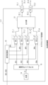
次に本発明の実施の形態2について説明する。実施の形態2では、実施の形態1で説明した光送信装置1_1の詳細な構成について説明する。図5は、実施の形態2にかかる光送信装置1_2を示すブロック図である。図5に示すように、本実施の形態にかかる光送信装置1_2は、複数のサブキャリア送信部11_1~11_m、出力部12、及び送信ポート13_1、13_2を備える。
<
Next, a second embodiment of the present invention will be described. In the second embodiment, a detailed configuration of the optical transmission device 1_1 described in the first embodiment will be described. Fig. 5 is a block diagram showing an optical transmission device 1_2 according to the second embodiment. As shown in Fig. 5, the optical transmission device 1_2 according to the present embodiment includes a plurality of subcarrier transmission units 11_1 to 11_m, an
複数のサブキャリア送信部11_1~11_mの各々には、送信データが供給される。複数のサブキャリア送信部(SCS_1~SCS_m)11_1~11_mは、送信データを送信するための光送信信号21_1~21_mをそれぞれ生成する。ここで、mは2以上の整数であり、サブキャリア送信部の数に対応している。光送信信号21_1~21_mは、サブキャリアを用いて送信データを送信するための信号である。例えば、サブキャリア送信部11_1は、サブキャリア送信部11_1に対応したサブキャリアSC1を用いて光送信信号21_1を生成する。また、サブキャリア送信部11_2は、サブキャリア送信部11_2に対応したサブキャリアSC2を用いて光送信信号21_2を生成する。このように、各々のサブキャリア送信部11_1~11_mは、各々のサブキャリア送信部11_1~11_mに対応した各々のサブキャリアSC1~SCmを用いて、各々の光送信信号21_1~21_mを生成する。 Transmission data is supplied to each of the multiple subcarrier transmitters 11_1 to 11_m. The multiple subcarrier transmitters (SCS_1 to SCS_m) 11_1 to 11_m generate optical transmission signals 21_1 to 21_m for transmitting the transmission data, respectively. Here, m is an integer equal to or greater than 2 and corresponds to the number of subcarrier transmitters. The optical transmission signals 21_1 to 21_m are signals for transmitting the transmission data using subcarriers. For example, the subcarrier transmitter 11_1 generates the optical transmission signal 21_1 using the subcarrier SC1 corresponding to the subcarrier transmitter 11_1. Also, the subcarrier transmitter 11_2 generates the optical transmission signal 21_2 using the subcarrier SC2 corresponding to the subcarrier transmitter 11_2. In this way, each of the subcarrier transmitters 11_1 to 11_m generates a respective optical transmission signal 21_1 to 21_m using a respective subcarrier SC1 to SCm corresponding to each of the subcarrier transmitters 11_1 to 11_m.
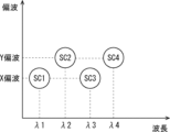
ここで各々の光送信信号21_1~21_m(換言すると、光送信信号21_1~21_mを生成する際に用いられる各々のサブキャリアSC1~SCm)は所定のパラメータを用いて設定することができる。このとき、各々の光送信信号21_1~21_mのパラメータが互いに重ならないように割り当てる。所定のパラメータとして複数のパラメータを用いた場合、複数のパラメータを軸としたマトリックス上において、各々の光送信信号21_1~21_mが互いに重ならないように配置する。例えば、所定のパラメータは、波長、偏波、時間のうちの少なくとも一つである。 Here, each of the optical transmission signals 21_1 to 21_m (in other words, each of the subcarriers SC1 to SCm used when generating the optical transmission signals 21_1 to 21_m) can be set using a predetermined parameter. At this time, the parameters of each of the optical transmission signals 21_1 to 21_m are assigned so that they do not overlap with each other. When multiple parameters are used as the predetermined parameters, each of the optical transmission signals 21_1 to 21_m is arranged on a matrix with the multiple parameters as axes so that they do not overlap with each other. For example, the predetermined parameter is at least one of the wavelength, polarization, and time.
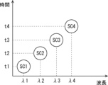
図6、図7は、サブキャリアの配置を説明するための図である。図6では、所定のパラメータとして波長と時間とを用いた場合のサブキャリアの配置の一例を示している。図6に示す場合は、波長をX軸とし時間をY軸としたマトリックス上(この場合は、XY平面上)において、各々のサブキャリアSC1~SC4を配置した際に、各々のサブキャリアSC1~SC4がマトリックス平面上において互いに重畳しないように配置している。図6に示す例では、各々のサブキャリアSC1~SC4の波長をそれぞれλ1~λ4に設定し、更に各々のサブキャリアSC1~SC4を時間t1~t4で時分割している。つまり、サブキャリアSC1はパラメータ(λ1、t1)、サブキャリアSC2はパラメータ(λ2、t2)、サブキャリアSC3はパラメータ(λ3、t3)、サブキャリアSC4はパラメータ(λ4、t4)を用いて設定することができる。 Figures 6 and 7 are diagrams for explaining the arrangement of subcarriers. Figure 6 shows an example of the arrangement of subcarriers when wavelength and time are used as the predetermined parameters. In the case shown in Figure 6, when each of the subcarriers SC1 to SC4 is arranged on a matrix (in this case, on an XY plane) with wavelength on the X axis and time on the Y axis, the subcarriers SC1 to SC4 are arranged so that they do not overlap with each other on the matrix plane. In the example shown in Figure 6, the wavelengths of each of the subcarriers SC1 to SC4 are set to λ1 to λ4, respectively, and each of the subcarriers SC1 to SC4 is time-divided by time t1 to t4. In other words, the subcarrier SC1 can be set using parameters (λ1, t1), the subcarrier SC2 can be set using parameters (λ2, t2), the subcarrier SC3 can be set using parameters (λ3, t3), and the subcarrier SC4 can be set using parameters (λ4, t4).
また、図7では、所定のパラメータとして波長と偏波とを用いた場合のサブキャリアの配置の一例を示している。図7に示す場合は、波長をX軸とし偏波をY軸としたマトリックス上(この場合は、XY平面上)において、各々のサブキャリアSC1~SC4を配置した際に、各々のサブキャリアSC1~SC4がマトリックス平面上において互いに重畳しないように配置している。図7に示す例では、各々のサブキャリアSC1~SC4の波長をそれぞれλ1~λ4に設定し、更に各々のサブキャリアSC1~SC4の偏波をX偏波、Y偏波に設定している。つまり、サブキャリアSC1はパラメータ(λ1、X偏波)、サブキャリアSC2はパラメータ(λ2、Y偏波)、サブキャリアSC3はパラメータ(λ3、X偏波)、サブキャリアSC4はパラメータ(λ4、Y偏波)を用いて設定することができる。 Also, FIG. 7 shows an example of subcarrier arrangement when wavelength and polarization are used as the predetermined parameters. In the case shown in FIG. 7, when each of the subcarriers SC1 to SC4 is arranged on a matrix (in this case, on the XY plane) with the wavelength on the X axis and the polarization on the Y axis, the subcarriers SC1 to SC4 are arranged so that they do not overlap with each other on the matrix plane. In the example shown in FIG. 7, the wavelengths of each of the subcarriers SC1 to SC4 are set to λ1 to λ4, respectively, and the polarizations of each of the subcarriers SC1 to SC4 are set to X polarization and Y polarization. In other words, the subcarrier SC1 can be set using parameters (λ1, X polarization), the subcarrier SC2 can be set using parameters (λ2, Y polarization), the subcarrier SC3 can be set using parameters (λ3, X polarization), and the subcarrier SC4 can be set using parameters (λ4, Y polarization).
このように、各々の光送信信号21_1~21_mのパラメータが互いに重ならないように割り当てることで、サブキャリア間の相互干渉の影響を低減することができる。なお、図6、図7では2つのパラメータを用いて各々のサブキャリアを設定した場合について説明したが、本実施の形態では3つ以上のパラメータを用いて各々のサブキャリアを設定してもよい。 In this way, by assigning the parameters of each of the optical transmission signals 21_1 to 21_m so that they do not overlap with each other, it is possible to reduce the effect of mutual interference between the subcarriers. Note that although the case where each subcarrier is set using two parameters has been described in Figures 6 and 7, in this embodiment, each subcarrier may be set using three or more parameters.
また上記パラメータとして波長を含む場合、複数のサブキャリア送信部11_1~11_mは、各々のサブキャリアSC1~SCmを生成するための光源(単一波長の光を出力する光源。不図示。)をそれぞれ備えていてもよい。例えば光源は、レーザダイオードを用いて構成することができる。 When the above parameters include wavelength, each of the multiple subcarrier transmitters 11_1 to 11_m may include a light source (a light source that outputs light of a single wavelength; not shown) for generating each of the subcarriers SC1 to SCm. For example, the light source may be configured using a laser diode.
また、サブキャリア送信部11_1~11_mは、所定の変調方式を用いて光送信信号21_1~21_mを変調してもよい。変調方式としては、振幅偏移変調(ASK)、周波数偏移変調(FSK)、位相偏移変調(PSK)、直交振幅変調(QAM)、四位相偏移変調(QPSK)などを挙げることができる。直交振幅変調(QAM)としては、例えば16QAM、64QAM、128QAM、256QAM等を用いることができる。 The subcarrier transmitters 11_1 to 11_m may also modulate the optical transmission signals 21_1 to 21_m using a predetermined modulation method. Examples of the modulation method include amplitude shift keying (ASK), frequency shift keying (FSK), phase shift keying (PSK), quadrature amplitude modulation (QAM), and quadrature phase shift keying (QPSK). For quadrature amplitude modulation (QAM), for example, 16QAM, 64QAM, 128QAM, and 256QAM can be used.
出力部12は、複数のサブキャリア送信部11_1~11_mから出力された各々の光送信信号21_1~21_mを、複数の送信ポート(PS_1、PS_2)13_1、13_2に選択的に出力する。ここで送信ポート13_1、13_2は、実施の形態1で説明した第1の経路26_1及び第2の経路26_2にそれぞれ対応している。このとき出力部12は、複数の光送信信号が多重化された光送信信号22_1を送信ポート13_1に出力する。例えば、出力部12が光送信信号21_1~21_5を送信ポート13_1に出力した場合、送信ポート13_1には光送信信号21_1~21_5が多重化された光送信信号22_1が供給される。同様に、出力部12は、複数の光送信信号が多重化された光送信信号22_2を送信ポート13_2に出力する。例えば、出力部12が光送信信号21_6~21_10を送信ポート13_2に出力した場合、送信ポート13_2には光送信信号21_6~21_10が多重化された光送信信号22_2が供給される。
The
出力部12は、各々の送信ポート13_1、13_2に供給される光送信信号21_1~21_mを任意かつ動的に切り替えることができる。例えば、出力部12は制御手段(不図示)を用いて制御される。
The
複数の送信ポート13_1、13_2は、出力部12から出力された光送信信号22_1、22_2(換言すると、サブキャリア送信部11_1~11_mから出力された光送信信号21_1~21_m)を送信可能に構成されている。つまり、送信ポート13_1は、接続先である第1の光受信装置(不図示)に光送信信号23_1(光送信信号22_1と同一)を出力する。また、送信ポート13_2は、接続先である第2の光受信装置(不図示)に光送信信号23_2(光送信信号22_2と同一)を出力する。 The multiple transmission ports 13_1, 13_2 are configured to be capable of transmitting optical transmission signals 22_1, 22_2 output from the output unit 12 (in other words, optical transmission signals 21_1 to 21_m output from the subcarrier transmission units 11_1 to 11_m). That is, the transmission port 13_1 outputs an optical transmission signal 23_1 (same as the optical transmission signal 22_1) to a first optical receiving device (not shown) to which it is connected. Also, the transmission port 13_2 outputs an optical transmission signal 23_2 (same as the optical transmission signal 22_2) to a second optical receiving device (not shown) to which it is connected.
なお、本実施の形態では、光送信装置1_2が2つの送信ポート13_1、13_2を備える場合を例として説明した。しかし、光送信装置1_2が備える送信ポートの数は、3つ以上であってもよい。送信ポートの数が3つ以上である場合、出力部12は、複数のサブキャリア送信部11_1~11_mから出力された各々の光送信信号21_1~21_mを、3以上の送信ポートに選択的に出力することができる。
In the present embodiment, the optical transmitting device 1_2 has two transmission ports 13_1, 13_2. However, the number of transmission ports provided in the optical transmitting device 1_2 may be three or more. When the number of transmission ports is three or more, the
このように本実施の形態にかかる光送信装置では、図5に示すように、複数の送信ポート13_1、13_2と出力部12とを設け、出力部12を用いて、複数のサブキャリア送信部11_1~11_mから出力された各々の光送信信号21_1~21_mを各々の送信ポート13_1、13_2に選択的に出力している。よって、例えば、送信ポート13_1を介して第1の光受信装置(不図示)にデータを送信している際に、使用していないサブキャリア送信部11_mが発生した場合、未使用のサブキャリア送信部11_mを用いて、送信ポート13_2を介して第2の光受信装置(不図示)にデータを送信することができる。
As shown in FIG. 5, the optical transmission device according to this embodiment is provided with a plurality of transmission ports 13_1, 13_2 and an
また、出力部12を用いて、それぞれの送信ポート13_1、13_2に供給される光送信信号21_1~21_mを動的に切り替えることで、送信ポート13_1を介した通信における伝送容量と、送信ポート13_2を介した通信における伝送容量とを、動的に調整することができる。
In addition, by dynamically switching the optical transmission signals 21_1 to 21_m supplied to each of the transmission ports 13_1 and 13_2 using the
以上で説明した本実施の形態にかかる発明により、光通信ネットワークにおいて、効率的なリソース配分を実施できる光送信装置及び光送信方法を提供することができる。 The invention according to the present embodiment described above makes it possible to provide an optical transmission device and an optical transmission method that can perform efficient resource allocation in an optical communication network.
<実施の形態3>
次に、本発明の実施の形態3について説明する。図8は、本実施の形態にかかる光送信装置1_3を示すブロック図である。本実施の形態にかかる光送信装置1_3では、実施の形態2で説明した光送信装置1_2と比べて、光源14、サブキャリア生成部15、及び信号変換部16を備えている点が異なる。これ以外は実施の形態2で説明した光送信装置1_2と同様であるので、同一の構成要素には同一の符号を付し、重複した説明は省略する。
<Third embodiment>
Next, a third embodiment of the present invention will be described. Fig. 8 is a block diagram showing an optical transmission device 1_3 according to this embodiment. The optical transmission device 1_3 according to this embodiment is different from the optical transmission device 1_2 described in the second embodiment in that it includes a
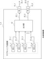
図8に示すように本実施の形態にかかる光送信装置1_3は、複数のサブキャリア送信部11’_1~11’_m、出力部12、送信ポート13_1、13_2、光源14、サブキャリア生成部15、及び信号変換部16を備える。
As shown in FIG. 8, the optical transmission device 1_3 according to this embodiment includes a plurality of subcarrier transmission units 11'_1 to 11'_m, an
光源14は単一のキャリアC1(単一波長の光)を出力する光源であり、例えばレーザダイオードを用いて構成することができる。光源14で生成されたキャリアC1はサブキャリア生成部15に出力される。
The
サブキャリア生成部15は、光源14で生成されたキャリアC1を用いて複数のサブキャリアSC1~SCmを生成し、生成された各々のサブキャリアSC1~SCmを各々のサブキャリア送信部11’_1~11’_mに供給する。このとき、サブキャリア生成部15は、光源14で生成されたキャリアC1を所定の変調方式を用いて変調することで複数のサブキャリアSC1~SCmを生成してもよい。
The
例えばサブキャリア生成部15は、光源14で生成されたキャリアC1を直交周波数分割多重方式(OFDM)を用いて変調することで、互いに直交している複数のサブキャリアSC1~SCmを生成してもよい。また、サブキャリア生成部15は、ナイキストWDM方式を用いて、複数のサブキャリアSC1~SCmを生成してもよい。このように、OFDM方式やナイキストWDM方式を用いて複数のサブキャリアSC1~SCmを生成することで、周波数間隔をシンボルレート間隔まで狭めることができ、スーパーチャネル技術を利用した通信において、周波数利用効率を高めることができる。
For example, the
例えば、各々のサブキャリア送信部11_1~11_m(実施の形態2参照)が備える各々の光源を用いてサブキャリアを生成した場合は、図9に示すように、各々のサブキャリアSC1~SC4の間隔は広くなる。一方、本実施の形態のように、光源14で生成されたキャリアC1をOFDM方式で変調することでサブキャリアを生成した場合は、図10に示すように、各々のサブキャリアSC1~SC4の間隔は図9に示す場合よりも狭くなり、周波数利用効率を高めることができる。
For example, when subcarriers are generated using the light sources provided in each of the subcarrier transmitters 11_1 to 11_m (see embodiment 2), the spacing between each of the subcarriers SC1 to SC4 becomes wider, as shown in FIG. 9. On the other hand, when subcarriers are generated by modulating the carrier C1 generated by the
このとき、各々のサブキャリアSC1~SCmの間隔は一定であることが好ましい。つまり、各々のサブキャリアSC1~SCmの波長間隔が変動する場合は、各々のサブキャリアSC1~SCmの波長の変動を考慮する必要があり、周波数利用効率が低下する。よって、本実施の形態にかかる光送信装置1_3では、光源14として単一光源を用いている。これにより、各々のサブキャリアSC1~SCmの間隔を一定にすることができる。
In this case, it is preferable that the spacing between each of the subcarriers SC1 to SCm is constant. In other words, if the wavelength spacing between each of the subcarriers SC1 to SCm varies, it is necessary to take into account the variation in the wavelength of each of the subcarriers SC1 to SCm, which reduces the frequency utilization efficiency. Therefore, in the optical transmission device 1_3 according to this embodiment, a single light source is used as the
信号変換部16は、入力された送信データDS1、DS2を直並列変換し、直並列変換されたデータDP1~DPmをそれぞれサブキャリア送信部11’_1~11’_mに出力する。サブキャリア送信部11’_1は、サブキャリアSC1を用いてデータDP1を送信するための光送信信号21_1を生成する。サブキャリア送信部11’_2は、サブキャリアSC2を用いてデータDP2を送信するための光送信信号21_2を生成する。このように、サブキャリア送信部11’_mは、サブキャリアSCmを用いてデータDPmを送信するための光送信信号21_mを生成する。
The
よって本実施の形態にかかる光送信装置1_3では、複数のサブキャリア送信部11’_1~11’_mは、各々のサブキャリア送信部11’_1~11’_mに対応した各々のサブキャリアSC1~SCmを用いて送信データDP1~DPmを並列に送信することができる。 Therefore, in the optical transmission device 1_3 according to this embodiment, the multiple subcarrier transmitters 11'_1 to 11'_m can transmit the transmission data DP1 to DPm in parallel using the subcarriers SC1 to SCm corresponding to each of the subcarrier transmitters 11'_1 to 11'_m.
つまり、複数のサブキャリア送信部11’_1~11’_mのうち送信ポート13_1を介して光送信信号22_1を送信する各々のサブキャリア送信部は、第1のデータを並列に送信することができる。また、複数のサブキャリア送信部11’_1~11’_mのうち送信ポート13_2を介して光送信信号22_2を送信する各々のサブキャリア送信部は、第2のデータを並列に送信することができる。 In other words, among the multiple subcarrier transmitters 11'_1 to 11'_m, each subcarrier transmitter that transmits the optical transmission signal 22_1 via the transmission port 13_1 can transmit the first data in parallel. Also, among the multiple subcarrier transmitters 11'_1 to 11'_m, each subcarrier transmitter that transmits the optical transmission signal 22_2 via the transmission port 13_2 can transmit the second data in parallel.
具体的に説明すると、例えば光送信装置1_3がサブキャリア送信部11’_1~11’_10を備えており、これらのサブキャリア送信部11’_1~11’_10のうち、サブキャリア送信部11’_1~11’_6が第1のデータDS1を送信ポート13_1を介して送信するものとする。また、サブキャリア送信部11’_7~11’_10が第2のデータDS2を送信ポート13_2を介して送信するものとする。 Specifically, for example, the optical transmitter 1_3 includes subcarrier transmitters 11'_1 to 11'_10, and among these subcarrier transmitters 11'_1 to 11'_10, subcarrier transmitters 11'_1 to 11'_6 transmit the first data DS1 via transmission port 13_1. Also, subcarrier transmitters 11'_7 to 11'_10 transmit the second data DS2 via transmission port 13_2.
この場合、信号変換部16は、入力された第1のデータDS1を直並列変換し、直並列変換された第1のデータDP1~DP6をそれぞれサブキャリア送信部11’_1~11’_6に出力する。サブキャリア送信部11’_1~11’_6はそれぞれ、サブキャリアSC1~SC6を用いて第1のデータDP1~DP6を送信するための光送信信号21_1~21_6を生成する。出力部12は、生成された光送信信号21_1~21_6を送信ポート13_1に出力する。これにより、多重化された光送信信号22_1が送信ポート13_1から出力される。よって、各々のサブキャリア送信部11’_1~11’_6は、直並列変換された第1のデータDS1を送信ポート13_1を介して並列に送信することができる。このとき、送信ポート13_1を介して送信される送信データのデータ幅は、送信ポート13_1に接続されるサブキャリア送信部11’_1~11’_6の数(つまり、データDP1~DP6)に対応している。
In this case, the
また、信号変換部16は、入力された第2のデータDS2を直並列変換し、直並列変換された第2のデータDP7~DP10をそれぞれサブキャリア送信部11’_7~11’_10に出力する。サブキャリア送信部11’_7~11’_10はそれぞれ、サブキャリアSC7~SC10を用いて第2のデータDP7~DP10を送信するための光送信信号21_7~21_10を生成する。出力部12は、生成された光送信信号21_7~21_10を送信ポート13_2に出力する。これにより、多重化された光送信信号22_2が送信ポート13_2から出力される。よって、各々のサブキャリア送信部11’_7~11’_10は、直並列変換された第2のデータDS2を送信ポート13_2を介して並列に送信することができる。このとき、送信ポート13_2を介して送信される送信データのデータ幅は、送信ポート13_2に接続されるサブキャリア送信部11’_7~11’_10の数(つまり、データDP7~DP10)に対応している。
The
送信ポート13_1を介して送信される送信データのデータ幅、及び送信ポート13_2を介して送信される送信データのデータ幅は、複数のサブキャリア送信部11’_1~11’_mから出力された各々の光送信信号21_1~21_mの出力先を、出力部12を用いて変更することで調整することができる。
The data width of the transmission data transmitted through transmission port 13_1 and the data width of the transmission data transmitted through transmission port 13_2 can be adjusted by changing the output destination of each of the optical transmission signals 21_1 to 21_m output from the multiple subcarrier transmission units 11'_1 to 11'_m using the
本実施の形態にかかる発明においても、光通信ネットワークにおいて、効率的なリソース配分を実施できる光送信装置及び光送信方法を提供することができる。 The invention according to this embodiment also provides an optical transmission device and an optical transmission method that can perform efficient resource allocation in an optical communication network.
<実施の形態4>
次に、本発明の実施の形態4について説明する。図11は、本実施の形態にかかる光送信装置1_4を示すブロック図である。本実施の形態にかかる光送信装置1_4では、実施の形態1乃至3で説明した光送信装置1_1~1_3が備える出力部12の具体的な構成例を示している。これ以外は実施の形態1乃至3で説明した光送信装置1_1~1_3と同様であるので、同一の構成要素には同一の符号を付し、重複した説明は省略する。
<Fourth embodiment>
Next, a fourth embodiment of the present invention will be described. Fig. 11 is a block diagram showing an optical transmission device 1_4 according to this embodiment. In the optical transmission device 1_4 according to this embodiment, a specific configuration example of the
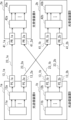
図11に示すように、本実施の形態にかかる光送信装置1_4が備える出力部12_1は、切替部30と光合波器31_1、31_2とを備える。切替部30は、各々のサブキャリア送信部11_1~11_mから出力された光送信信号21_1~21_mの出力先を光合波器31_1または光合波器31_2のいずれか一方に切り替える。切替部30は、例えばm入力、m×2出力の光マトリックススイッチを用いて構成することができる。ここで、切替部30のm入力は各々の光送信信号21_1~21_mの数に対応している。例えば、切替部30は、制御手段(不図示)を用いて制御される。
As shown in FIG. 11, the output unit 12_1 of the optical transmission device 1_4 according to this embodiment includes a
複数の光合波器31_1、31_2は、各々の送信ポート13_1、13_2と対応するように設けられ、切替部30から出力された各々の光送信信号21_1~21_mを合波する。つまり、光合波器31_1は、切替部30から出力された各々の光送信信号を合波して多重化し、多重化された光送信信号22_1を送信ポート13_1に出力する。同様に、光合波器31_2は、切替部30から出力された各々の光送信信号を合波して多重化し、多重化された光送信信号22_2を送信ポート13_2に出力する。
Multiple optical multiplexers 31_1, 31_2 are provided corresponding to the respective transmission ports 13_1, 13_2, and multiplex the respective optical transmission signals 21_1 to 21_m output from the switching
このように、本実施の形態にかかる光送信装置1_4では、切替部30と光合波器31_1、31_2とを用いて出力部12_1を構成している。よって、各々の送信ポート13_1、13_2に供給される光送信信号21_1~21_mを動的に切り替えることができる。
In this way, in the optical transmission device 1_4 according to this embodiment, the output section 12_1 is configured using the
なお、切替部30は、図12に示す光送信装置1_5が備える出力部12_2のように、複数の光スイッチSW_1~SW_mを用いて構成してもよい。この場合、複数の光スイッチSW_1~SW_mは、各々のサブキャリア送信部11_1~11_mと対応するように設けられ、各々のサブキャリア送信部11_1~11_mから出力された光送信信号21_1~21_mの出力先を、光合波器31_1または光合波器31_2に切り替える。
The switching
例えば光スイッチSW_1は、サブキャリア送信部11_1と対応するように設けられており、サブキャリア送信部11_1から出力された光送信信号21_1を、光合波器31_1または光合波器31_2のいずれか一方に出力する。光スイッチSW_2は、サブキャリア送信部11_2と対応するように設けられており、サブキャリア送信部11_2から出力された光送信信号21_2を、光合波器31_1または光合波器31_2のいずれか一方に出力する。各々の光スイッチSW_1~SW_mは、制御手段(不図示)を用いて制御される。 For example, optical switch SW_1 is provided to correspond to subcarrier transmitter 11_1, and outputs optical transmission signal 21_1 output from subcarrier transmitter 11_1 to either optical multiplexer 31_1 or optical multiplexer 31_2. Optical switch SW_2 is provided to correspond to subcarrier transmitter 11_2, and outputs optical transmission signal 21_2 output from subcarrier transmitter 11_2 to either optical multiplexer 31_1 or optical multiplexer 31_2. Each of the optical switches SW_1 to SW_m is controlled using a control means (not shown).
また、出力部は、図13に示す光送信装置1_6が備える出力部12_3のように、光合波器32と光分波器33とを用いて構成してもよい。この場合、光合波器32は、各々のサブキャリア送信部11_1~11_mから出力された各々の光送信信号21_1~21_mを合波して多重化し、多重化された光信号25を光分波器33に出力する。光分波器33は、光合波器32から出力された多重化された光信号25に含まれている各々の光送信信号21_1~21_mを送信ポート13_1、13_2に選択的に出力する。
The output unit may also be configured using an
例えば光分波器33は、多重化された光信号25に含まれている光送信信号21_1を、送信ポート13_1または送信ポート13_2のいずれか一方に出力する。また、光分波器33は、多重化された光信号25に含まれている光送信信号21_2を、送信ポート13_1または送信ポート13_2のいずれか一方に出力する。
For example, the
例えば、光分波器33は、多重化された光信号25に含まれている各々の光送信信号21_1~21_mを、波長に応じて送信ポート13_1、13_2に選択的に出力してもよい。
For example, the
<実施の形態5>
次に、本発明の実施の形態5について説明する。図14は、実施の形態5にかかる光受信装置2_1を示すブロック図である。図14に示すように、本実施の形態にかかる光受信装置2_1は、切替部42、第1の受信部43_1および第2の受信部43_2を備える。なお、以下では第1及び第2の受信部をサブキャリア受信部という場合もある。
<Fifth embodiment>
Next, a fifth embodiment of the present invention will be described. Fig. 14 is a block diagram showing an optical receiving device 2_1 according to the fifth embodiment. As shown in Fig. 14, the optical receiving device 2_1 according to the present embodiment includes a
切替部42は、入力された各々の光受信信号51_1、51_2を受信し、これらに含まれるサブキャリア受信信号52_1、52_2を第1の受信部43_1および第2の受信部43_2に選択的に出力する。換言すると切替部42は、光受信信号51_1、51_2に含まれるサブキャリア受信信号の出力先(第1及び第2の受信部43_1、43_2)を任意かつ動的に切り替えることができる。例えば、切替部42は制御手段(不図示)を用いて制御される。
The switching
第1の受信部43_1は、サブキャリア受信信号52_1を用いて伝送されたデータを受信する。第2の受信部43_2は、サブキャリア受信信号52_2を用いて伝送されたデータを受信する。第1の受信部43_1及び第2の受信部43_2は、各々のサブキャリア受信信号52_1、52_2を検波するための検波部(不図示)を備える。各々の検波部は局部発振器を備えていてもよい。 The first receiving unit 43_1 receives data transmitted using the subcarrier reception signal 52_1. The second receiving unit 43_2 receives data transmitted using the subcarrier reception signal 52_2. The first receiving unit 43_1 and the second receiving unit 43_2 each include a detection unit (not shown) for detecting the subcarrier reception signals 52_1 and 52_2. Each detection unit may include a local oscillator.
本実施の形態にかかる光受信装置2_1では、切替部42は、第1のサブキャリア受信信号52_1及び第2のサブキャリア受信信号52_2が一連の情報を共有する場合、第1のサブキャリア受信信号52_1及び第2のサブキャリア受信信号52_2を同一の経路を経由して受信する。例えば、切替部42は、第1のサブキャリア受信信号52_1及び第2のサブキャリア受信信号52_2が含まれている光受信信号51_1を受信することで、第1のサブキャリア受信信号52_1及び第2のサブキャリア受信信号52_2を同一の経路を経由して受信することができる。このとき、切替部42は、第1のサブキャリア受信信号52_1を第1の受信部43_1に、第2のサブキャリア受信信号52_2を第2の受信部43_2にそれぞれ出力する。
In the optical receiving device 2_1 according to this embodiment, when the first subcarrier reception signal 52_1 and the second subcarrier reception signal 52_2 share a series of information, the switching
一方、切替部42は、第1のサブキャリア受信信号52_1及び第2のサブキャリア受信信号52_2が一連の情報を共有しない場合、第1のサブキャリア受信信号52_1及び第2のサブキャリア受信信号52_2をそれぞれ異なる経路を経由して受信する。例えば光受信信号51_1に第1のサブキャリア受信信号52_1が含まれており、光受信信号51_2に第2のサブキャリア受信信号52_2が含まれている場合、切替部42は光受信信号51_1及び光受信信号51_1を受信することで、第1のサブキャリア受信信号52_1及び第2のサブキャリア受信信号52_2をそれぞれ異なる経路を経由して受信することができる。このとき、切替部42は、第1のサブキャリア受信信号を第1の受信部43_1に出力し、第2のサブキャリア受信信号を第2の受信部43_2に出力する。
On the other hand, when the first subcarrier reception signal 52_1 and the second subcarrier reception signal 52_2 do not share a series of information, the switching
ここで、第1のサブキャリア受信信号52_1及び第2のサブキャリア受信信号52_2が一連の情報を共有する場合とは、例えば、第1のサブキャリア受信信号52_1及び第2のサブキャリア受信信号52_2を用いて所定のデータが並列に伝送される場合である。 Here, the first subcarrier reception signal 52_1 and the second subcarrier reception signal 52_2 share a series of information when, for example, predetermined data is transmitted in parallel using the first subcarrier reception signal 52_1 and the second subcarrier reception signal 52_2.
一方、第1のサブキャリア受信信号52_1及び第2のサブキャリア受信信号52_2が一連の情報を共有しない場合とは、例えば、第1のサブキャリア受信信号52_1及び第2のサブキャリア受信信号52_2が所定のデータを独立に伝送する場合である。例えば、第1の光送信装置(不図示)が第1のデータを第1のサブキャリア受信信号52_1を用いて伝送し、第2の光送信装置(不図示)が第2のデータを第2のサブキャリア受信信号52_2を用いて伝送する場合である。このとき、光受信装置2_1は、第1の光送信装置(不図示)から伝送された第1のサブキャリア受信信号52_1を第1の経路を経由して受信し、第2の光送信装置(不図示)から伝送された第2のサブキャリア受信信号52_2を第2の経路を経由して受信する。 On the other hand, when the first subcarrier reception signal 52_1 and the second subcarrier reception signal 52_2 do not share a series of information, for example, the first subcarrier reception signal 52_1 and the second subcarrier reception signal 52_2 transmit predetermined data independently. For example, the first optical transmission device (not shown) transmits the first data using the first subcarrier reception signal 52_1, and the second optical transmission device (not shown) transmits the second data using the second subcarrier reception signal 52_2. In this case, the optical reception device 2_1 receives the first subcarrier reception signal 52_1 transmitted from the first optical transmission device (not shown) via the first path, and receives the second subcarrier reception signal 52_2 transmitted from the second optical transmission device (not shown) via the second path.
このように、本実施の形態にかかる光受信装置2_1では、第1のサブキャリア受信信号52_1及び第2のサブキャリア受信信号52_2を、第1の受信部43_1及び第2の受信部43_2に切替部42を用いて選択的に出力している。
In this way, in the optical receiving device 2_1 according to this embodiment, the first subcarrier reception signal 52_1 and the second subcarrier reception signal 52_2 are selectively output to the first receiving unit 43_1 and the second receiving unit 43_2 using the
よって実施の形態1で説明した理由と同様の理由により、光通信ネットワークにおいて、効率的なリソース配分を実施できる光受信装置及び光受信方法を提供することができる。 Therefore, for the same reasons as those explained in the first embodiment, it is possible to provide an optical receiving device and an optical receiving method capable of performing efficient resource allocation in an optical communication network.
<実施の形態6>
次に、本発明の実施の形態6について説明する。図15は、実施の形態6にかかる光受信装置2_2を示すブロック図である。実施の形態6では、実施の形態5で説明した光受信装置2_1の詳細な構成について説明する。図15に示すように、本実施の形態にかかる光受信装置2_2は、複数の受信ポート41_1、41_2、切替部42、サブキャリア受信部43_1~43_m、及び信号処理部45を備える。
<Sixth embodiment>
Next, a sixth embodiment of the present invention will be described. Fig. 15 is a block diagram showing an optical receiving device 2_2 according to the sixth embodiment. In the sixth embodiment, a detailed configuration of the optical receiving device 2_1 described in the fifth embodiment will be described. As shown in Fig. 15, the optical receiving device 2_2 according to the present embodiment includes a plurality of receiving ports 41_1, 41_2, a switching
複数の受信ポート(PR_1、PR_2)41_1、41_2は、光受信装置2_2に供給された多重化された光受信信号50_1、50_2をそれぞれ受信し、受信した光受信信号51_1、51_2をそれぞれ切替部42に出力する。受信ポート41_1、41_2はそれぞれ、異なる光送信装置から伝送された光受信信号50_1、50_2を受信することができる。例えば、受信ポート41_1は第1の光送信装置(不図示)から伝送された光受信信号50_1を受信し、受信ポート41_2は第2の光送信装置(不図示)から伝送された光受信信号50_2を受信することができる。
The multiple receiving ports (PR_1, PR_2) 41_1, 41_2 respectively receive the multiplexed optical receiving signals 50_1, 50_2 supplied to the optical receiving device 2_2, and output the received optical receiving signals 51_1, 51_2 to the
切替部42は、複数の受信ポート41_1、41_2で受信した各々の光受信信号51_1、51_2に含まれる各々のサブキャリア受信信号52_1~52_mを、複数のサブキャリア受信部(SCR_1~SCR_m)43_1~43_mに選択的に出力する。換言すると、多重化されている各々の光受信信号51_1、51_2は、切替部42において各々のサブキャリア受信信号52_1~52_mに分離される。そして、分離された各々のサブキャリア受信信号52_1~52_mは、各々のサブキャリア受信信号52_1~52_mに対応するサブキャリア受信部43_1~43_m(つまり、各々の波長のサブキャリア受信信号を受信できるサブキャリア受信部)にそれぞれ出力される。このとき、1つのサブキャリア受信部43_mには1つのサブキャリア受信信号52_mが入力される。
The switching
切替部42は、各々のサブキャリア受信信号52_1~52_mの出力先(サブキャリア受信部43_1~43_m)を任意かつ動的に切り替えることができる。例えば、切替部42は制御手段(不図示)を用いて制御される。
The switching
サブキャリア受信部43_1は、サブキャリア受信信号52_1を用いて伝送されたデータを受信する。サブキャリア受信部43_2は、サブキャリア受信信号52_2を用いて伝送されたデータを受信する。このように、サブキャリア受信部43_mは、サブキャリア受信信号52_mを用いて伝送された各々のデータを受信する。各々のサブキャリア受信部43_1~43_mは、各々のサブキャリア受信信号52_1~52_mを検波するための検波部(不図示)を備える。各々の検波部は局部発振器を備えていてもよい。つまり、各々のサブキャリア受信部43_1~43_mは、各々の局部発振器で生成された局部発振光と入力された各々のサブキャリア受信信号52_1~52_mとを干渉させることで、各々のサブキャリア受信部43_1~43_mに対応したサブキャリア受信信号52_1~52_mを受信することができる。 The subcarrier receiving unit 43_1 receives data transmitted using the subcarrier reception signal 52_1. The subcarrier receiving unit 43_2 receives data transmitted using the subcarrier reception signal 52_2. In this way, the subcarrier receiving unit 43_m receives each data transmitted using the subcarrier reception signal 52_m. Each of the subcarrier receiving units 43_1 to 43_m includes a detection unit (not shown) for detecting each of the subcarrier reception signals 52_1 to 52_m. Each detection unit may include a local oscillator. In other words, each of the subcarrier receiving units 43_1 to 43_m can receive the subcarrier reception signals 52_1 to 52_m corresponding to each of the subcarrier receiving units 43_1 to 43_m by causing interference between the local oscillation light generated by each of the local oscillators and each of the input subcarrier reception signals 52_1 to 52_m.
各々のサブキャリア受信信号52_1~52_mは、所定の変調方式を用いて変調されていてもよい。この場合、サブキャリア受信部43_1~43_mは、所定の変調方式で変調されたサブキャリア受信信号52_1~52_mからデータを読み出すための回路を備えている。所定の変調方式としては、振幅偏移変調(ASK)、周波数偏移変調(FSK)、位相偏移変調(PSK)、直交振幅変調(QAM)、四位相偏移変調(QPSK)などを挙げることができる。直交振幅変調(QAM)としては、例えば16QAM、64QAM、128QAM、256QAM等を用いることができる。 Each of the subcarrier reception signals 52_1 to 52_m may be modulated using a predetermined modulation method. In this case, the subcarrier reception units 43_1 to 43_m are provided with a circuit for reading data from the subcarrier reception signals 52_1 to 52_m modulated by the predetermined modulation method. Examples of the predetermined modulation method include amplitude shift keying (ASK), frequency shift keying (FSK), phase shift keying (PSK), quadrature amplitude modulation (QAM), and quadrature phase shift keying (QPSK). As the quadrature amplitude modulation (QAM), for example, 16QAM, 64QAM, 128QAM, 256QAM, etc. can be used.
また、本実施の形態にかかる光受信装置2_2では、複数のサブキャリア受信部43_1~43_mのうち受信ポート41_1を介してサブキャリア受信信号(光受信信号50_1)を受信した各々のサブキャリア受信部は、直並列変換された第1のデータを並列に受信することができる。また、複数のサブキャリア受信部43_1~43_mのうち第2の受信ポート41_2を介してサブキャリア受信信号(光受信信号50_2)を受信した各々のサブキャリア受信部は、直並列変換された第2のデータを並列に受信することができる。換言すると、受信ポート41_1を介して受信した光受信信号50_1に含まれるサブキャリア受信信号の各々は一連の情報を共有している。また、受信ポート41_2を介して受信した光受信信号50_2に含まれるサブキャリア受信信号の各々は一連の情報を共有している。 In the optical receiving device 2_2 according to the present embodiment, each of the subcarrier receiving units 43_1 to 43_m that receives a subcarrier receiving signal (optical receiving signal 50_1) via the receiving port 41_1 can receive the serial-to-parallel converted first data in parallel. Also, each of the subcarrier receiving units 43_1 to 43_m that receives a subcarrier receiving signal (optical receiving signal 50_2) via the second receiving port 41_2 can receive the serial-to-parallel converted second data in parallel. In other words, each of the subcarrier receiving signals included in the optical receiving signal 50_1 received via the receiving port 41_1 shares a series of information. Also, each of the subcarrier receiving signals included in the optical receiving signal 50_2 received via the receiving port 41_2 shares a series of information.
具体的に説明すると、例えば光受信装置2_2がサブキャリア受信部43_1~43_10を備えており、これらのサブキャリア受信部43_1~43_10のうち、サブキャリア受信部43_1~43_6が第1のデータを受信ポート41_1を介して受信するものとする。また、サブキャリア受信部43_7~43_10が第2のデータを受信ポート41_2を介して受信するものとする。 To explain in more detail, for example, the optical receiving device 2_2 is equipped with subcarrier receiving units 43_1 to 43_10, and among these subcarrier receiving units 43_1 to 43_10, subcarrier receiving units 43_1 to 43_6 receive the first data via receiving port 41_1. Also, subcarrier receiving units 43_7 to 43_10 receive the second data via receiving port 41_2.
この場合、光受信装置2_2は第1の光送信装置(不図示)から伝送された光受信信号50_1を受信ポート41_1を介して受信する。そして、サブキャリア受信部43_1~43_6は、光受信信号50_1に含まれるサブキャリア受信信号52_1~52_6を各々受信することで、第1のデータ(第1の光送信装置で直並列変換されたデータ)を並列に受信することができる。このように並列に伝送されてきた第1のデータは、後段の信号処理部45で直列のデータに変換することができる。
In this case, the optical receiving device 2_2 receives the optical receiving signal 50_1 transmitted from the first optical transmitting device (not shown) via the receiving port 41_1. Then, the subcarrier receiving units 43_1 to 43_6 can receive the first data (data converted from serial to parallel by the first optical transmitting device) in parallel by respectively receiving the subcarrier receiving signals 52_1 to 52_6 contained in the optical receiving signal 50_1. The first data transmitted in parallel in this way can be converted to serial data by the
同様に、光受信装置2_2は第2の光送信装置(不図示)から伝送された光受信信号50_2を受信ポート41_2を介して受信する。そして、サブキャリア受信部43_7~43_10は、光受信信号50_2に含まれるサブキャリア受信信号52_7~52_10を各々受信することで、第2のデータ(第2の光送信装置で直並列変換されたデータ)を並列に受信することができる。このように並列に伝送されてきた第2のデータは、後段の信号処理部45で直列のデータに変換することができる。
Similarly, the optical receiving device 2_2 receives the optical receiving signal 50_2 transmitted from the second optical transmitting device (not shown) via the receiving port 41_2. Then, the subcarrier receiving units 43_7 to 43_10 can receive the second data (data converted from serial to parallel by the second optical transmitting device) in parallel by respectively receiving the subcarrier receiving signals 52_7 to 52_10 contained in the optical receiving signal 50_2. The second data transmitted in parallel in this way can be converted to serial data by the
例えば、各々のサブキャリア受信部43_1~43_mは光電変換器(不図示)を備えている。各々の光電変換器は、サブキャリア受信信号52_1~52_mを電気信号に変換し、当該電気信号を受信信号53_1~53_mとして信号処理部45に出力する。光電変換器には、例えばフォトダイオードを用いることができる。
For example, each of the subcarrier receiving units 43_1 to 43_m includes an opto-electrical converter (not shown). Each opto-electrical converter converts the subcarrier receiving signals 52_1 to 52_m into an electrical signal, and outputs the electrical signal to the
信号処理部45は、サブキャリア受信部43_1~43_mから出力された受信信号53_1~53_mに対して所定の処理を行いデータを生成する。また、信号処理部45は、各々のサブキャリア受信信号52_1~52_m間の相互干渉の影響を補償してもよい。つまり、信号処理部45において各々のサブキャリア受信部43_1~43_mを同時に処理することで、例えばクロストークの補償や非線形光学効果(相互位相変調(XPM)、四光波混合(FWM)など)の補償を行うことができる。例えば信号処理部45は、各々のサブキャリア受信信号52_1~52_mに応じて、各々のサブキャリア受信部43_1~43_mが備える各々の局部発振器を制御することで、各々のサブキャリア受信信号52_1~52_m間の相互干渉の影響を補償してもよい。
The
スーパーチャネル技術では、1チャネルの帯域において複数の波長(サブキャリア)を使用しており、波長が高密度に多重されている。このため、サブキャリア間における相互干渉の影響が大きい。本実施の形態にかかる光受信装置では、複数の異なるサブキャリアを同一の光受信装置で受信しており、一つのサブキャリアに影響する隣接するサブキャリアも同時にモニタすることができる。このため、サブキャリア受信信号間の相互干渉の影響を補償するための補償パラメータを設定することができる。 In super-channel technology, multiple wavelengths (subcarriers) are used in one channel band, and the wavelengths are multiplexed at high density. This means that the effects of mutual interference between subcarriers are large. In the optical receiving device according to this embodiment, multiple different subcarriers are received by the same optical receiving device, and adjacent subcarriers that affect one subcarrier can also be monitored simultaneously. This makes it possible to set compensation parameters to compensate for the effects of mutual interference between subcarrier reception signals.
なお、本実施の形態では、光受信装置2_2が2つの受信ポート41_1、41_2を備える場合を例として説明した。しかし、光受信装置2_2が備える受信ポートの数は、3つ以上であってもよい。 In the present embodiment, the optical receiving device 2_2 is described as having two receiving ports 41_1 and 41_2. However, the number of receiving ports provided in the optical receiving device 2_2 may be three or more.
実施の形態1で説明した場合と同様に、光受信装置が1つの受信ポートしか備えていない場合は次のような問題が生じる。すなわち、光受信装置が1つの受信ポートを介して第1の光送信装置(不図示)からデータを受信している際に、使用していないサブキャリア受信部が発生した場合は、この未使用のサブキャリア受信部が使用できず、リソースが無駄になるという問題があった。つまり、受信ポートが1つしかない場合は、未使用のサブキャリア受信部を用いて他の光送信装置からデータを受信することができず、未使用のサブキャリア受信部が無駄になるという問題があった。 As in the case described in the first embodiment, if the optical receiving device has only one receiving port, the following problem occurs. That is, when the optical receiving device is receiving data from a first optical transmitting device (not shown) via one receiving port, if an unused subcarrier receiving unit occurs, this unused subcarrier receiving unit cannot be used, resulting in a problem of wasting resources. In other words, if there is only one receiving port, the unused subcarrier receiving unit cannot be used to receive data from other optical transmitting devices, resulting in a problem of wasting the unused subcarrier receiving unit.
そこで本実施の形態にかかる光受信装置2_2では、図15に示すように、複数の受信ポート41_1、41_2と切替部42とを設け、切替部42を用いて、複数の受信ポート41_1、41_2で受信した各々の光受信信号51_1、51_2に含まれる各々のサブキャリア受信信号52_1~52_mを、複数のサブキャリア受信部43_1~43_mに選択的に出力している。よって、例えば、未使用のサブキャリア受信部が発生した場合に、空いている受信ポートを介して他の光送信装置(不図示)から光受信信号を受信し、未使用のサブキャリア受信部においてこの光受信信号を用いてデータを受信することができる。
In the optical receiving device 2_2 according to the present embodiment, as shown in FIG. 15, multiple receiving ports 41_1, 41_2 and a
なお、上記では1つのサブキャリア受信部43_mに1つのサブキャリア受信信号52_mが入力される場合について説明したが、本実施の形態にかかる光受信装置2_2では、1つのサブキャリア受信部43_mに複数のサブキャリア受信信号が入力され、1つのサブキャリア受信部43_mで複数のサブキャリア受信信号を選択的に受信するように構成してもよい。この場合は、各々のサブキャリア受信部43_1~43_mに局部発振器(不図示)を設け、局部発振器から出力された特定波長の局部発振光と入力された複数のサブキャリア受信信号(多重化されたサブキャリア受信信号)とを干渉させることで、複数のサブキャリア受信信号の中から特定のサブキャリア受信信号(つまり、特定波長に対応したサブキャリア受信信号)を選択的に受信することができる。このように、複数のサブキャリア受信信号が1つのサブキャリア受信部43_mに入力されることを許容することで、切替部42の構成を簡素化することができる。
In the above, a case where one subcarrier reception signal 52_m is input to one subcarrier reception unit 43_m has been described, but in the optical receiving device 2_2 according to this embodiment, multiple subcarrier reception signals may be input to one subcarrier reception unit 43_m, and the multiple subcarrier reception signals may be selectively received by one subcarrier reception unit 43_m. In this case, a local oscillator (not shown) is provided in each of the subcarrier reception units 43_1 to 43_m, and a specific subcarrier reception signal (i.e., a subcarrier reception signal corresponding to a specific wavelength) can be selectively received from the multiple subcarrier reception signals by interfering with the local oscillation light of a specific wavelength output from the local oscillator and the multiple subcarrier reception signals (multiplexed subcarrier reception signals) input. In this way, the configuration of the switching
以上で説明した本実施の形態にかかる発明により、光通信ネットワークにおいて、効率的なリソース配分を実施できる光受信装置及び光受信方法を提供することができる。 The invention according to the present embodiment described above makes it possible to provide an optical receiving device and an optical receiving method that can perform efficient resource allocation in an optical communication network.
<実施の形態7>
次に、本発明の実施の形態7について説明する。図16は、本実施の形態にかかる光受信装置2_3を示すブロック図である。本実施の形態にかかる光受信装置2_3では、複数のサブキャリア受信部が局部発振器(LO)を共有している点が実施の形態6にかかる光受信装置2_2と異なる。これ以外は実施の形態6で説明した光受信装置2_2と同様であるので、同一の構成要素には同一の符号を付し、重複した説明は省略する。
<Seventh embodiment>
Next, a seventh embodiment of the present invention will be described. Fig. 16 is a block diagram showing an optical receiving device 2_3 according to this embodiment. The optical receiving device 2_3 according to this embodiment differs from the optical receiving device 2_2 according to the sixth embodiment in that a local oscillator (LO) is shared by a plurality of subcarrier receiving units. Other than this, the optical receiving device 2_3 is similar to the optical receiving device 2_2 described in the sixth embodiment, so the same components are given the same reference numerals and duplicated descriptions are omitted.
図16に示すように、本実施の形態にかかる光受信装置2_3は、複数の受信ポート41_1、41_2、切替部42、サブキャリア受信部43_1~43_6、局部発振器44_1、44_2及び信号処理部45を備える。本実施の形態にかかる光受信装置2_3では、複数のサブキャリア受信部が局部発振器を共有している。すなわち、複数のサブキャリア受信部43_1~43_3は、局部発振器44_1を共有している。また、複数のサブキャリア受信部43_4~43_6は、局部発振器44_2を共有している。図16に示す例では、サブキャリア受信部の数を6としている(m=6)が、サブキャリア受信部の数はこれ以外であってもよい。このとき、局部発振器の数はサブキャリア受信部の数に応じて増やすことができる。また、図16に示す例では、1つの局部発振器を3つのサブキャリア受信部で共有している例を示すが、1つの局部発振器を共有するサブキャリア受信部の数は2つであってもよく、また4つ以上であってもよい。
As shown in FIG. 16, the optical receiving device 2_3 according to the present embodiment includes a plurality of receiving ports 41_1, 41_2, a switching
切替部42は、複数の受信ポート41_1、41_2で受信した各々の光受信信号51_1、51_2に含まれる各々のサブキャリア受信信号52_1~52_6を、複数のサブキャリア受信部43_1~43_6に選択的に出力する。換言すると、多重化されている各々の光受信信号51_1、51_2は、切替部42において各々のサブキャリア受信信号52_1~52_6に分離される。そして、分離された各々のサブキャリア受信信号52_1~52_6は、各々のサブキャリア受信信号52_1~52_6に対応するサブキャリア受信部43_1~43_6にそれぞれ出力される。このとき、1つのサブキャリア受信部に1つのサブキャリア受信信号が入力される。
The switching
切替部42は、各々のサブキャリア受信信号52_1~52_6の出力先を任意かつ動的に切り替えることができる。例えば、切替部42は制御手段(不図示)を用いて制御される。
The switching
サブキャリア受信部43_1~43_6は、各々のサブキャリア受信信号52_1~52_6を用いて伝送された各々のデータを受信する。各々のサブキャリア受信部43_1~43_6は、各々のサブキャリア受信信号52_1~52_6を検波するための検波部(不図示)を備える。このとき、各々のサブキャリア受信部43_1~43_6が備える検波部は、局部発振器44_1、44_2から出力された局部発振光を用いて検波を行うことができる。 The subcarrier receiving units 43_1 to 43_6 receive the data transmitted using the subcarrier receiving signals 52_1 to 52_6. Each of the subcarrier receiving units 43_1 to 43_6 includes a detection unit (not shown) for detecting each of the subcarrier receiving signals 52_1 to 52_6. At this time, the detection unit included in each of the subcarrier receiving units 43_1 to 43_6 can perform detection using the local oscillation light output from the local oscillators 44_1 and 44_2.
つまりサブキャリア受信部43_1~43_3は、局部発振器44_1から出力された局部発振光を用いて各々のサブキャリア受信信号52_1~52_3を検波することができる。このとき、局部発振器44_1は、各々のサブキャリア受信信号52_1~52_3に対応した波長(各々のサブキャリア受信信号52_1~52_3と干渉する波長)を有する局部発振光を生成する。すなわち、サブキャリア受信信号52_1~52_3の波長が互いに近接している場合は、局部発振器44_1から出力された局部発振光が単一の波長を有する局部発振光であっても、各々のサブキャリア受信信号52_1~52_3は当該局部発振光と干渉する。よって、各々のサブキャリア受信部43_1~43_3は、局部発振器44_1から出力された局部発振光を用いて各々のサブキャリア受信信号52_1~52_3を検波することができる。 That is, the subcarrier receiving units 43_1 to 43_3 can detect each of the subcarrier receiving signals 52_1 to 52_3 using the local oscillation light output from the local oscillator 44_1. At this time, the local oscillator 44_1 generates local oscillation light having a wavelength corresponding to each of the subcarrier receiving signals 52_1 to 52_3 (a wavelength that interferes with each of the subcarrier receiving signals 52_1 to 52_3). That is, when the wavelengths of the subcarrier receiving signals 52_1 to 52_3 are close to each other, even if the local oscillation light output from the local oscillator 44_1 has a single wavelength, each of the subcarrier receiving signals 52_1 to 52_3 interferes with the local oscillation light. Therefore, each of the subcarrier receiving units 43_1 to 43_3 can detect each of the subcarrier receiving signals 52_1 to 52_3 using the local oscillation light output from the local oscillator 44_1.
同様に、サブキャリア受信部43_4~43_6は、局部発振器44_2から出力された局部発振光を用いて各々のサブキャリア受信信号52_4~52_6を検波することができる。このとき、局部発振器44_2は、各々のサブキャリア受信信号52_4~52_6に対応した波長(各々のサブキャリア受信信号52_4~52_6と干渉する波長)を有する局部発振光を生成する。すなわち、サブキャリア受信信号52_4~52_6の波長が互いに近接している場合は、局部発振器44_2から出力された局部発振光が単一の波長を有する局部発振光であっても、各々のサブキャリア受信信号52_4~52_6は当該局部発振光と干渉する。よって、各々のサブキャリア受信部43_4~43_6は、局部発振器44_2から出力された局部発振光を用いて各々のサブキャリア受信信号52_4~52_6を検波することができる。例えば局部発振器44_1、44_2は、レーザダイオードを用いて構成することができる。 Similarly, the subcarrier receiving units 43_4 to 43_6 can detect each of the subcarrier receiving signals 52_4 to 52_6 using the local oscillator light output from the local oscillator 44_2. At this time, the local oscillator 44_2 generates local oscillator light having a wavelength corresponding to each of the subcarrier receiving signals 52_4 to 52_6 (a wavelength that interferes with each of the subcarrier receiving signals 52_4 to 52_6). In other words, when the wavelengths of the subcarrier receiving signals 52_4 to 52_6 are close to each other, even if the local oscillator light output from the local oscillator 44_2 is a local oscillator light having a single wavelength, each of the subcarrier receiving signals 52_4 to 52_6 interferes with the local oscillator light. Therefore, each of the subcarrier receiving units 43_4 to 43_6 can detect each of the subcarrier receiving signals 52_4 to 52_6 using the local oscillator light output from the local oscillator 44_2. For example, local oscillators 44_1 and 44_2 can be constructed using laser diodes.
例えば、各々のサブキャリア受信部43_1~43_6は光電変換器(不図示)を備えている。各々の光電変換器は、サブキャリア受信信号52_1~52_6を電気信号に変換し、当該電気信号を受信信号53_1~53_6として信号処理部45に出力する。光電変換器には、例えばフォトダイオードを用いることができる。
For example, each of the subcarrier receiving units 43_1 to 43_6 includes an opto-electrical converter (not shown). Each opto-electrical converter converts the subcarrier receiving signals 52_1 to 52_6 into an electrical signal, and outputs the electrical signal to the
信号処理部45は、サブキャリア受信部43_1~43_6から出力された受信信号53_1~53_6に対して所定の処理を行いデータを生成する。また信号処理部45は、サブキャリア受信部43_1~43_6から出力された受信信号53_1~53_6に応じて、局部発振器44_1、44_2を制御することができる。換言すると、光受信信号51_1、51_2に含まれるサブキャリア受信信号52_1~52_6に応じて局部発振器44_1、44_2が制御される。
The
例えば信号処理部45は、複数のサブキャリア受信部に対応したサブキャリア受信信号が光受信信号51_1、51_2に含まれていない場合、複数のサブキャリア受信部で共有している局部発振器をオフ状態としてもよい。具体的に説明すると、サブキャリア受信部43_1~43_3に対応するサブキャリア受信信号52_1~52_3の全てが光受信信号51_1、51_2に含まれていない場合、サブキャリア受信部43_1~43_3で共有している局部発振器44_1をオフ状態とすることができる。同様に、サブキャリア受信部43_4~43_6に対応するサブキャリア受信信号52_4~52_6の全てが光受信信号51_1、51_2に含まれていない場合、サブキャリア受信部43_4~43_6で共有している局部発振器44_2をオフ状態とすることができる。このような制御により、不要な局部発振器をオフ状態とすることができ、光受信装置2_3の消費電力を低減することができる。
For example, when the optical reception signal 51_1, 51_2 does not include a subcarrier reception signal corresponding to a plurality of subcarrier reception units, the
また、実施の形態6の場合と同様に、信号処理部45において複数のサブキャリア受信信号を同時に処理することで、例えばクロストークの補償や非線形光学効果(相互位相変調(XPM)、四光波混合(FWM)など)の補償を行うことができる。
Also, as in the sixth embodiment, multiple subcarrier reception signals can be processed simultaneously in the
以上で説明した本実施の形態にかかる発明により、光通信ネットワークにおいて、効率的なリソース配分を実施できる光受信装置及び光受信方法を提供することができる。 The invention according to the present embodiment described above makes it possible to provide an optical receiving device and an optical receiving method that can perform efficient resource allocation in an optical communication network.
<実施の形態8>
次に、本発明の実施の形態8について説明する。図17は、本実施の形態にかかる光受信装置2_4を示すブロック図である。本実施の形態にかかる光受信装置2_4では、実施の形態5乃至7で説明した光受信装置2_1~2_3が備える切替部42の具体的な構成例を示している。これ以外は実施の形態5乃至7で説明した光受信装置2_1~2_3と同様であるので、同一の構成要素には同一の符号を付し、重複した説明は省略する。
<Embodiment 8>
Next, an eighth embodiment of the present invention will be described. Fig. 17 is a block diagram showing an optical receiving device 2_4 according to this embodiment. In the optical receiving device 2_4 according to this embodiment, a specific configuration example of the switching
図17に示すように、本実施の形態にかかる光受信装置2_4が備える切替部42_1は、光分岐器60_1、60_2と光切替スイッチ61とを備える。光分岐器60_1、60_2は、各々の受信ポート41_1、41_2と対応するように設けられ、各々の受信ポート41_1、41_2で受信した光受信信号51_1、51_2を分岐して、光切替スイッチ61に出力する。
As shown in FIG. 17, the switching unit 42_1 of the optical receiving device 2_4 according to this embodiment includes optical splitters 60_1 and 60_2 and an
光切替スイッチ61は、各々の光分岐器60_1、60_2で分岐された光受信信号を入力し、これらを各々のサブキャリア受信部43_1~43_mに選択的に出力する。例えば、光切替スイッチ61はm×2入力、m出力の光マトリックススイッチを用いて構成することができる。ここで、光切替スイッチ61のm出力はサブキャリア受信部43_1~43_mの数に対応している。例えば、光切替スイッチ61は、制御手段(不図示)を用いて制御される。
The
このように、本実施の形態にかかる光受信装置2_4では、光分岐器60_1、60_2と光切替スイッチ61とを用いて切替部42_1を構成している。よって、各々のサブキャリア受信部43_1~43_mに供給されるサブキャリア受信信号52_1~52_mを動的に切り替えることができる。
In this way, in the optical receiving device 2_4 according to this embodiment, the switching unit 42_1 is configured using the optical splitters 60_1 and 60_2 and the
なお、光切替スイッチ61は、図18に示す光受信装置2_5が備える切替部42_2のように、複数の光スイッチSW_1~SW_mを用いて構成してもよい。この場合、光スイッチSW_1~SW_mは、各々のサブキャリア受信部43_1~43_mと対応するように設けられ、各々の光分岐器60_1、60_2で分岐された光受信信号の中から各々のサブキャリア受信部43_1~43_mに出力する光受信信号を選択して出力する。
The
例えば、光スイッチSW_1はサブキャリア受信部43_1と対応するように設けられており、光分岐器60_1、60_2で分岐された光受信信号の中から、サブキャリア受信部43_1に対応するサブキャリア受信信号52_1を選択し、当該選択したサブキャリア受信信号52_1をサブキャリア受信部43_1に出力する。光スイッチSW_2はサブキャリア受信部43_2と対応するように設けられており、光分岐器60_1、60_2で分岐された光受信信号の中から、サブキャリア受信部43_2に対応するサブキャリア受信信号52_2を選択し、当該選択したサブキャリア受信信号52_2をサブキャリア受信部43_2に出力する。各々の光スイッチSW_1~SW_mは、制御手段(不図示)を用いて制御される。例えば光スイッチSW_1~SW_mは、波長選択型の光スイッチで構成することができる。 For example, the optical switch SW_1 is provided to correspond to the subcarrier receiving unit 43_1, and selects the subcarrier receiving signal 52_1 corresponding to the subcarrier receiving unit 43_1 from among the optical reception signals branched by the optical branchers 60_1 and 60_2, and outputs the selected subcarrier receiving signal 52_1 to the subcarrier receiving unit 43_1. The optical switch SW_2 is provided to correspond to the subcarrier receiving unit 43_2, and selects the subcarrier receiving signal 52_2 corresponding to the subcarrier receiving unit 43_2 from among the optical reception signals branched by the optical branchers 60_1 and 60_2, and outputs the selected subcarrier receiving signal 52_2 to the subcarrier receiving unit 43_2. Each of the optical switches SW_1 to SW_m is controlled using a control means (not shown). For example, the optical switches SW_1 to SW_m can be configured as a wavelength selection type optical switch.
また、例えば実施の形態6の後半で説明した光受信装置のように、サブキャリア受信部43_1~43_mがそれぞれ、特定のサブキャリア受信信号を選択的に受信することができるのであれば、1つのサブキャリア受信部43_mに複数のサブキャリア受信信号が入力されるようにしてもよい。この場合は、例えば光スイッチSW_1~SW_mのそれぞれは、複数のサブキャリア受信信号を1つのサブキャリア受信部43_mに出力することができる。
Also, for example, as in the optical receiving device described in the latter half of
また切替部は、図19に示す光受信装置2_6が備える切替部42_3のように、光合波器62と光分波器63とを用いて構成してもよい。光合波器62は、各々の受信ポート41_1、41_2で受信した光受信信号51_1、51_2を合波して多重化し、多重化された光信号64を光分波器63に出力する。光分波器63は、多重化された光信号64に含まれている各々のサブキャリア受信信号52_1~52_mを、各々のサブキャリア受信部43_1~43_mに選択的に出力する。
The switching unit may also be configured using an
つまり光分波器63は、多重化された光信号64に含まれているサブキャリア受信信号52_1を、サブキャリア受信部43_1に出力する。また、光分波器63は、多重化された光信号64に含まれているサブキャリア受信信号52_2を、サブキャリア受信部43_2に出力する。
That is, the
例えば、光分波器63は、多重化された光信号64に含まれている各々のサブキャリア受信信号52_1~52_mを、波長に応じてサブキャリア受信部43_1~43_mに選択的に出力することができる。この場合、光分波器63は、波長選択型の光分波器63を用いて構成することができる。
For example, the
また、例えば実施の形態6の後半で説明した光受信装置のように、サブキャリア受信部43_1~43_mがそれぞれ、特定のサブキャリア受信信号を選択的に受信することができるのであれば、1つのサブキャリア受信部43_mに複数のサブキャリア受信信号が入力されるようにしてもよい。この場合は、例えば光分波器62は、多重化された光信号63の中に含まれる複数のサブキャリア受信信号を1つのサブキャリア受信部43_mに出力することができる。例えば、光分波器63の代わりに光分岐器を用いてもよい。
Also, for example, as in the optical receiving device described in the latter half of
<実施の形態9>
次に、本発明の実施の形態9について説明する。図20は、本実施の形態にかかる光通信装置3を示すブロック図である。本実施の形態にかかる光通信装置3は送受信可能な光通信装置であり、実施の形態1で説明した光送信装置1_1と実施の形態5で説明した光受信装置2_1とを組み合わせた構成となっている。
<Ninth embodiment>
Next, a ninth embodiment of the present invention will be described. Fig. 20 is a block diagram showing an
図20に示すように、本実施の形態にかかる光通信装置3は、第1の送信部11_1、第2の送信部11_2、出力部12、切替部42、第1の受信部43_1、及び第2の受信部43_2を備える。光送信信号22_1及び光受信信号51_1は、第1の経路を介して送受信可能に構成されている。また、光送信信号22_2及び光受信信号51_2は、第2の経路を介して送受信可能に構成されている。
As shown in FIG. 20, the
なお、第1の送信部11_1、第2の送信部11_2、及び出力部12の構成及び動作については、実施の形態1で説明した光送信装置1_1の場合と同様であるので重複した説明は省略する。また、切替部42、第1の受信部43_1、及び第2の受信部43_2の構成及び動作については、実施の形態5で説明した光受信装置2_1の場合と同様であるので重複した説明は省略する。
The configurations and operations of the first transmitting unit 11_1, the second transmitting unit 11_2, and the
また、本実施の形態にかかる光通信装置3においても、実施の形態2乃至4で説明した光送信装置1_2~1_6の構成を適用してもよく、また実施の形態6乃至8で説明した光受信装置2_2~2_6の構成を適用してもよい。
In addition, the
以上で説明した本実施の形態にかかる発明より、光通信ネットワークにおいて、効率的なリソース配分を実施できる光通信装置及び光通信方法を提供することができる。 The invention according to the present embodiment described above makes it possible to provide an optical communication device and an optical communication method capable of performing efficient resource allocation in an optical communication network.
<実施の形態10>
次に、本発明の実施の形態10について説明する。図21は、本実施の形態にかかる光通信システムを示すブロック図である。図21に示すように、本実施の形態にかかる光通信システムは、光送信装置1と、当該光送信装置1と通信を行う光受信装置70_1、70_2とを備える。光送信装置1には、実施の形態1乃至4で説明した光送信装置1_1~1_6を用いることができる。
<Tenth embodiment>
Next, a tenth embodiment of the present invention will be described. Fig. 21 is a block diagram showing an optical communication system according to this embodiment. As shown in Fig. 21, the optical communication system according to this embodiment includes an
光送信装置1は、複数のサブキャリア送信部11_1~11_m、出力部12、及び送信ポート13_1、13_2を備える。複数のサブキャリア送信部11_1~11_mは、サブキャリアを用いてデータを送信する光送信信号21_1~21_mをそれぞれ生成する。出力部12は、複数のサブキャリア送信部11_1~11_mから出力された各々の光送信信号21_1~21_mを送信ポート13_1または送信ポート13_2に選択的に出力する。なお、光送信装置1の構成及び動作については、実施の形態1乃至4で説明した光送信装置1_1~1_6と同様であるので重複した説明は省略する。
The
送信ポート13_1は光受信装置70_1の受信ポート71_1と光ファイバを介して接続され、送信ポート13_2は光受信装置70_2の受信ポート71_2と光ファイバを介して接続されている。光送信装置1は、光受信装置70_1に送信ポート13_1を介して光送信信号23_1を送信する。また、光送信装置1は、光受信装置70_2に送信ポート13_2を介して光送信信号23_2を送信する。光送信信号23_1は、複数の光送信信号21_mが多重化された信号である。光受信装置70_1が備える受信部72_1は、このような多重化された光送信信号を受信可能に構成されている。同様に、光送信信号23_2は、複数の光送信信号21_mが多重化された信号である。光受信装置70_2が備える受信部72_2は、このような多重化された光送信信号を受信可能に構成されている。
The transmission port 13_1 is connected to the reception port 71_1 of the optical receiving device 70_1 via an optical fiber, and the transmission port 13_2 is connected to the reception port 71_2 of the optical receiving device 70_2 via an optical fiber. The
複数のサブキャリア送信部11_1~11_mのうち送信ポート13_1を介して光送信信号を送信する各々のサブキャリア送信部は、直並列変換された第1のデータを光受信装置70_1に並列に送信してもよい。また、複数のサブキャリア送信部11_1~11_mのうち送信ポート13_2を介して光送信信号を送信する各々のサブキャリア送信部は、直並列変換された第2のデータを光受信装置70_2に並列に送信してもよい。 Of the multiple subcarrier transmitters 11_1 to 11_m, each subcarrier transmitter that transmits an optical transmission signal via transmission port 13_1 may transmit serial-to-parallel converted first data in parallel to the optical receiving device 70_1. Also, of the multiple subcarrier transmitters 11_1 to 11_m, each subcarrier transmitter that transmits an optical transmission signal via transmission port 13_2 may transmit serial-to-parallel converted second data in parallel to the optical receiving device 70_2.
つまり、光送信装置1は、光受信装置70_1に送信する第1のデータを直並列変換し、当該直並列変換された各々のデータを送信するための光送信信号をサブキャリア送信部で生成して光受信装置70_1に送信する。光受信装置70_1は、光送信信号23_1に含まれる直並列変換されたデータを受信し、受信した直並列変換されたデータを並直列変換することで、並直列変換された第1のデータを取得することができる。光受信装置70_2に送信される第2のデータについても同様である。
In other words, the
また、本実施の形態にかかる光通信システムでは、光送信装置1と光受信装置70_1との間の伝送容量は、送信ポート13_1に光送信信号を出力するサブキャリア送信部11_1~11_mの数に基づき決定される。同様に、光送信装置1と光受信装置70_2との間の伝送容量は、送信ポート13_2に光送信信号を出力するサブキャリア送信部11_1~11_mの数に基づき決定される。換言すると、光送信信号23_1の伝送容量と光送信信号23_2の伝送容量の比は、送信ポート13_1に接続されるサブキャリア送信部の数と送信ポート13_2に接続されるサブキャリア送信部の数との比に対応している。例えば、光送信装置1と光受信装置70_1との間の伝送容量を増加させる場合は、出力部12を制御して、送信ポート13_1に接続されるサブキャリア送信部の数を増加させる。
In the optical communication system according to the present embodiment, the transmission capacity between the
また、光送信装置1と光受信装置70_1との間の伝送には第1の波長帯域のサブキャリアを用いてもよく、光送信装置1と光受信装置70_2との間の伝送には第2の波長帯域のサブキャリアを用いてもよい。ここで、第1の波長帯域と第2の波長帯域は互いに波長が重ならない帯域である。例えば、これらの波長帯域は、WDMで用いられているCバンド、Lバンド、Sバンド等である。
In addition, a subcarrier in a first wavelength band may be used for transmission between the
また、光送信装置1と光受信装置70_1との間の通信の設定は、光送信装置1と光受信装置70_1との間の距離、通信を行う時間帯、及び光送信装置1と光受信装置70_1との間の伝送経路の状態の少なくとも一つに応じて決定してもよい。また、光送信装置1と光受信装置70_1との間の通信におけるサブキャリアの波長帯域の割り当て、光信号の経路、及び変調方式の少なくとも一つを用いて、光送信装置1と光受信装置70_1との間の通信の設定を行ってもよい。光送信装置1と光受信装置70_2との間の通信の設定についても同様である。
The settings for communication between the
例えば、光送信装置1と光受信装置70_1との間の通信距離が長くなるにつれて、1つのサブキャリア当たりの多値度を減少させると共にサブキャリアの数を増加させてもよい。逆に、光送信装置1と光受信装置70_1との間の通信距離が短くなるにつれて、1つのサブキャリア当たりの多値度を増加させると共にサブキャリアの数を減少させてもよい。
For example, as the communication distance between the
直交振幅変調(QAM)を用いた場合を例として具体的に説明すると、光送信装置1と光受信装置70_1との間の通信距離が長い場合、128QAMや256QAM等の変調方式を用いて1つのサブキャリア当たりの多値度を増加させると、ビット誤り率が増加する。よってこの場合は、16QAMや64QAM等の変調方式を用いて、1つのサブキャリア当たりの多値度を減少させる。また、この場合は1つのサブキャリアに含まれる情報量が少なくなるので、この分だけサブキャリアの数を増加させる。
To give a specific example of a case where quadrature amplitude modulation (QAM) is used, if the communication distance between the
一方、光送信装置1と光受信装置70_1との間の通信距離が短い場合は、128QAMや256QAM等の変調方式を用いて1つのサブキャリア当たりの多値度を増加させることができる。この場合は、1つのサブキャリアに含まれる情報量を増加させることができるので、この分だけサブキャリアの数を減少させることができる。
On the other hand, if the communication distance between the
また、例えば、光送信装置1と光受信装置70_1との間の伝送経路が悪化した場合(光ファイバにテンションが作用した場合など)は、例えば1つのサブキャリア当たりの多値度を減少させてもよい。このように1つのサブキャリア当たりの多値度を減少させることで、ビット誤り率の増加を抑制することができる。
In addition, for example, if the transmission path between the
なお、上記で説明したような光通信システムにおける通信の取り決めは、光送信装置1及び光受信装置70_1、70_1が決定することができる。
The communication arrangements in the optical communication system described above can be determined by the
以上で説明した本実施の形態にかかる発明により、光通信ネットワークにおいて、効率的なリソース配分を実施できる光通信システム及び光通信システムの制御方法を提供することができる。 The invention according to the present embodiment described above can provide an optical communication system and a method for controlling the optical communication system that can perform efficient resource allocation in an optical communication network.
<実施の形態11>
次に、本発明の実施の形態11について説明する。図22は、本実施の形態にかかる光通信システムを示すブロック図である。図22に示すように、本実施の形態にかかる光通信システムは、光送信装置1と、当該光送信装置1と通信を行う光受信装置70_1、70_2と、コントローラ80とを備える。なお、本実施の形態にかかる光通信システムは、コントローラ80を備える点以外は、実施の形態10で説明した光通信システムと同様であるので重複した説明は省略する。また、本実施の形態においても、光送信装置1には、実施の形態1乃至4で説明した光送信装置1_1~1_6を用いることができる。
<
Next, an eleventh embodiment of the present invention will be described. FIG. 22 is a block diagram showing an optical communication system according to this embodiment. As shown in FIG. 22, the optical communication system according to this embodiment includes an
コントローラ80は、光送信装置1及び光受信装置70_1、70_2をそれぞれ制御するために設けられている。つまり、コントローラ80は、光送信装置1と光受信装置70_1の通信状態及び光送信装置1と光受信装置70_2の通信状態に応じて、光送信装置1や光受信装置70_1、70_2を制御することができる。
The
図23はコントローラ80の構成例を示すブロック図である。図23に示すように、コントローラ80は、監視部81及び設定部82を備える。監視部81は、光通信システムの通信状態、つまり光送信装置1と光受信装置70_1の通信状態及び光送信装置1と光受信装置70_2の通信状態を監視する。設定部82は、監視部81における監視結果に応じて、光送信装置1や光受信装置70_1、70_2をそれぞれ設定する。
Fig. 23 is a block diagram showing an example of the configuration of the
コントローラ80は、光送信装置1と光受信装置70_1との通信で使用するサブキャリア送信部や光送信装置1と光受信装置70_2との通信で使用するサブキャリア送信部を設定することができる。このとき、コントローラ80は、光送信装置1が備える出力部12の設定を変更することで、各々の光受信装置70_1、70_2との通信で使用するサブキャリア送信部を変更することができる。
The
例えばコントローラ80は、送信ポート13_1、13_2に光送信信号を出力するサブキャリア送信部11_1~11_mの数を制御することで、光送信装置1と光受信装置70_1との間の伝送容量及び光送信装置1と光受信装置70_2との間の伝送容量を変更することができる。
For example, the
またコントローラ80は、光送信装置1と光受信装置70_1との通信で使用するサブキャリアの波長帯域や光送信装置1と光受信装置70_2との通信で使用するサブキャリアの波長帯域を設定することができる。例えばコントローラ80は、光送信装置1と光受信装置70_1との間の通信には第1の波長帯域のサブキャリアが用いられるように、また光送信装置1と光受信装置70_2との間の通信には第2の波長帯域のサブキャリアが用いられるように設定することができる。ここで、第1の波長帯域と第2の波長帯域は互いに波長が重ならない帯域である。例えば、これらの波長帯域は、WDMで用いられているCバンド、Lバンド、Sバンド等である。
The
またコントローラ80は、光送信装置1と光受信装置70_1との間の距離、通信を行う時間帯、及び光送信装置1と光受信装置70_1との間の伝送経路の状態の少なくとも一つに応じて、光送信装置1と光受信装置70_1との間の通信の設定を行うことができる。またコントローラ80は、光送信装置1と光受信装置70_1との間の通信におけるサブキャリアの波長帯域の割り当て、光信号の経路、及び変調方式の少なくとも一つを用いて、光送信装置1と光受信装置70_1との間の通信の設定を行ってもよい。光送信装置1と光受信装置70_2との間の通信の設定についても同様である。
The
例えばコントローラ80は、光送信装置1と光受信装置70_1との間の通信距離が長くなるにつれて、1つのサブキャリア当たりの多値度を減少させると共にサブキャリアの数を増加させてもよい。逆に、光送信装置1と光受信装置70_1との間の通信距離が短くなるにつれて、1つのサブキャリア当たりの多値度を増加させると共にサブキャリアの数を減少させてもよい。光送信装置1と光受信装置70_2との間の通信における変調方式についても同様である。
For example, the
また、コントローラ80は、光送信装置1と光受信装置70_1との間の伝送経路が悪化した場合(光ファイバにテンションが作用した場合など)は、例えば1つのサブキャリア当たりの多値度を減少させてもよい。このように1つのサブキャリア当たりの多値度を減少させることで、ビット誤り率の増加を抑制することができる。光送信装置1と光受信装置70_2との間の通信における変調方式についても同様である。
In addition, when the transmission path between the
本実施の形態では1つの光送信装置と2つの光受信装置とで構成された光通信システムを例として挙げたが、光通信システムを構成する光送信装置及び光受信装置はこれ以上備えていてもよい。この場合もコントローラ80は、光通信システム全体が最適な通信状態となるように光送信装置や光受信装置を設定することができる。
In this embodiment, an optical communication system composed of one optical transmitting device and two optical receiving devices is given as an example, but the optical communication system may include more optical transmitting devices and optical receiving devices. In this case, the
ここで最適な通信状態はユーザに応じて任意に決定することができる。一例を挙げると、通信コストを最小化する通信状態、通信の信頼性を最大化する通信状態(つまり、通信が途切れないことを最優先とした通信状態であり、冗長経路を考慮した通信状態)、通信速度を重視した通信状態(常に最短経路となるような通信状態)、波長使用効率が最大となる通信状態などである。 The optimal communication state can be determined arbitrarily by the user. Examples include a communication state that minimizes communication costs, a communication state that maximizes communication reliability (i.e., a communication state that prioritizes uninterrupted communication and takes redundant routes into consideration), a communication state that prioritizes communication speed (a communication state that always uses the shortest route), a communication state that maximizes wavelength usage efficiency, etc.
またコントローラ80は、光送信装置や光受信装置から報告されるネットワークの状態の変化(例えば光伝送路における障害や光通信信号の劣化など)に関する情報を収集し、ネットワークの状態の変化に追従するように、また光通信システム全体が最適な通信状態となるように光送信装置や光受信装置を再設定することができる。
The
以上で説明した本実施の形態にかかる発明により、光通信ネットワークにおいて、効率的なリソース配分を実施できる光通信システム及び光通信システムの制御方法を提供することができる。また、光通信システム全体が最適な通信状態となるような光通信システム及び光通信システムの制御方法を提供することができる。 The invention according to the present embodiment described above can provide an optical communication system and a method for controlling the optical communication system that can perform efficient resource allocation in an optical communication network. It can also provide an optical communication system and a method for controlling the optical communication system that can bring the entire optical communication system into an optimal communication state.
<実施の形態12>
次に、本発明の実施の形態12について説明する。本実施の形態では、本発明にかかる光通信システムを集中制御型のネットワークに適用した場合について説明する。図24は、本実施の形態にかかる光通信システムを示すブロック図である。図24に示すように、本実施の形態にかかる光通信システムは、コントローラ80及び複数のノードA~D(85_a~85_d)を備える。コントローラ80は、実施の形態11で説明したコントローラ80と対応している。また複数のノードA~D(85_a~85_d)は、通信ネットワークを構成する要素である。複数のノードA~D(85_a~85_d)には、例えば実施の形態1乃至4で説明した光送信装置1_1~1_6、実施の形態5乃至8で説明した光受信装置2_1~2_6、または実施の形態9で説明した光通信装置3を用いることができる。
<Twelfth embodiment>
Next, a twelfth embodiment of the present invention will be described. In this embodiment, a case where the optical communication system according to the present invention is applied to a centralized control network will be described. FIG. 24 is a block diagram showing an optical communication system according to this embodiment. As shown in FIG. 24, the optical communication system according to this embodiment includes a
コントローラ80は、各ノード85_a~85_dの通信状態を監視し、各ノード85_a~85_dの通信状態に応じて、各ノード85_a~85_dを制御する。コントローラ80は、各ノード85_a~85_dを制御するための制御信号86_a~86_dを各ノード85_a~85_dに出力する。
The
コントローラ80は、各ノード85_a~85_dで使用するリソース配分の取り決め(例えば、使用するサブキャリア送受信部の取り決め)や光信号の経路の取り決めを行うことができる。例えばコントローラ80は、ノード85_aとノード85_bとの通信で使用するサブキャリアを決定することで、ノード85_aとノード85_bとの間の伝送容量を変更することができる。
The
またコントローラ80は、各ノード85_a~85_d間における通信で使用するサブキャリアの波長帯域を設定することができる。例えばコントローラ80は、ノード85_aとノード85_bとの間の通信には第1の波長帯域のサブキャリアが用いられるように、またノード85_aとノード85_dとの間の通信には第2の波長帯域のサブキャリアが用いられるように設定することができる。ここで、第1の波長帯域と第2の波長帯域は互いに波長が重ならない帯域である。例えば、これらの波長帯域は、WDMで用いられているCバンド、Lバンド、Sバンド等である。
The
またコントローラ80は、各ノード85_a~85_d間の距離、通信を行う時間帯、及び各ノード85_a~85_d間の伝送経路の状態の少なくとも一つに応じて、各ノード85_a~85_d間の通信の設定を行うことができる。ここで通信を行う時間帯とは、例えば所定の時間帯(昼夜間)、所定の時期、所定のイベント(バックアップの実施等)の時間帯等である。またコントローラ80は、各ノード85_a~85_d間の通信におけるサブキャリアの波長帯域の割り当て、光信号の経路、及び変調方式の少なくとも一つを用いて、各ノード85_a~85_d間の通信の設定を行ってもよい。
The
例えばコントローラ80は、ノード85_aとノード85_bとの間の通信距離が長くなるにつれて、1つのサブキャリア当たりの多値度を減少させると共にサブキャリアの数を増加させてもよい。逆に、ノード85_aとノード85_bとの間の通信距離が短くなるにつれて、1つのサブキャリア当たりの多値度を増加させると共にサブキャリアの数を減少させてもよい。他のノード間における変調方式についても同様である。
For example, the
また、コントローラ80は、ノード85_aとノード85_bとの間の伝送経路が悪化した場合(光ファイバにテンションが作用した場合など)は、例えば1つのサブキャリア当たりの多値度を減少させてもよい。このように1つのサブキャリア当たりの多値度を減少させることで、ビット誤り率の増加を抑制することができる。他のノード間における変調方式についても同様である。
In addition, when the transmission path between node 85_a and node 85_b deteriorates (when tension acts on the optical fiber, for example), the
本実施の形態では4つのノード85_a~85_dを備える光通信システムを例として挙げたが、光通信システムを構成するノードの数はこれ以上であってもよい。 In this embodiment, an optical communication system having four nodes 85_a to 85_d is given as an example, but the number of nodes constituting the optical communication system may be more than this.
コントローラ80は、光通信システム全体が最適な通信状態となるように光送信装置や光受信装置を設定することができる。ここで最適な通信状態はユーザに応じて任意に決定することができる。一例を挙げると、通信コストを最小化する通信状態、通信の信頼性を最大化する通信状態(つまり、通信が途切れないことを最優先とした通信状態であり、冗長経路を考慮した通信状態)、通信速度を重視した通信状態(常に最短経路となるような通信状態)、波長使用効率が最大となる通信状態などである。
The
またコントローラ80は、光送信装置や光受信装置から報告されるネットワークの状態の変化(例えば光伝送路における障害や光通信信号の劣化など)に関する情報を収集し、ネットワークの状態の変化に追従するように、また光通信システム全体が最適な通信状態となるように光送信装置や光受信装置を再設定することができる。
The
例えば、ノード85_aからノード85_bに最短経路87_1でデータを伝送している際に、この最短経路87_1に障害が発生した場合、コントローラ80は、通信が途切れないように、ノード85_aとノード85_dとをつなぐ経路87_2、ノード85_dとノード85_cとをつなぐ経路87_3、及びノード85_cとノード85_bとをつなぐ経路87_4を経由してノード85_bにデータを伝送する冗長経路に切り替えることができる。
For example, if a failure occurs in the shortest path 87_1 while data is being transmitted from node 85_a to node 85_b, the
以上で説明した本実施の形態にかかる発明により、光通信ネットワークにおいて、効率的なリソース配分を実施できる光通信システム及び光通信システムの制御方法を提供することができる。また、光通信システム全体が最適な通信状態となるような光通信システム及び光通信システムの制御方法を提供することができる。 The invention according to the present embodiment described above can provide an optical communication system and a method for controlling the optical communication system that can perform efficient resource allocation in an optical communication network. It can also provide an optical communication system and a method for controlling the optical communication system that can bring the entire optical communication system into an optimal communication state.
<実施の形態13>
次に、本発明の実施の形態13について説明する。図25は、本実施の形態にかかる光通信システムを示すブロック図である。図25に示すように、本実施の形態にかかる光通信システムは、光受信装置2と、当該光受信装置2と通信を行う光送信装置75_1、75_2とを備える。光受信装置2には、実施の形態5乃至8で説明した光受信装置2_1~2_6を用いることができる。
<
Next, a thirteenth embodiment of the present invention will be described. Fig. 25 is a block diagram showing an optical communication system according to this embodiment. As shown in Fig. 25, the optical communication system according to this embodiment includes an
光受信装置2は、受信ポート41_1、41_2、切替部42、及び複数のサブキャリア受信部43_1~43_mを備える。受信ポート41_1、41_2はそれぞれ、多重化された光受信信号50_1、50_2を受信する。切替部42は、受信ポート41_1、41_2で受信した各々の光受信信号51_1、51_2に含まれる各々のサブキャリア受信信号52_1~52_mを複数のサブキャリア受信部43_1~43_mに選択的に出力する。複数のサブキャリア受信部43_1~43_mは、サブキャリア受信信号52_1~52_mに含まれる各々のデータを受信する。なお、光受信装置2の構成及び動作については、実施の形態5乃至8で説明した光受信装置2_1~2_6と同様であるので重複した説明は省略する。
The
光送信装置75_1が備える送信部77_1は、複数のサブキャリアを用いて生成された多重化された光送信信号を送信可能に構成されている。光送信装置75_2が備える送信部77_2は、複数のサブキャリアを用いて生成された多重化された光送信信号を送信可能に構成されている。受信ポート41_1は光送信装置75_1の送信ポート76_1と光ファイバを介して接続され、受信ポート41_2は光送信装置75_2の送信ポート76_2と光ファイバを介して接続されている。光受信装置2は、光送信装置75_1から伝送された光受信信号50_1を受信ポート41_1を介して受信する。また、光受信装置2は、光送信装置75_2から伝送された光受信信号50_2を受信ポート41_2を介して受信する。
The transmitting unit 77_1 of the optical transmitting device 75_1 is configured to be capable of transmitting a multiplexed optical transmission signal generated using multiple subcarriers. The transmitting unit 77_2 of the optical transmitting device 75_2 is configured to be capable of transmitting a multiplexed optical transmission signal generated using multiple subcarriers. The receiving port 41_1 is connected to the transmitting port 76_1 of the optical transmitting device 75_1 via an optical fiber, and the receiving port 41_2 is connected to the transmitting port 76_2 of the optical transmitting device 75_2 via an optical fiber. The
このとき、複数のサブキャリア受信部43_1~43_mのうち受信ポート41_1を介して光受信信号を受信する各々のサブキャリア受信部は、光送信装置75_1から送信された第1のデータ(直並列変換されたデータ)を並列に受信してもよい。また、複数のサブキャリア受信部43_1~43_mのうち受信ポート41_2を介して光受信信号を受信する各々のサブキャリア受信部は、光送信装置75_2から送信された第2のデータ(直並列変換されたデータ)を並列に受信してもよい。 At this time, each of the subcarrier receivers 43_1 to 43_m that receives the optical reception signal via reception port 41_1 may receive the first data (serial-parallel converted data) transmitted from the optical transmitter 75_1 in parallel. Also, each of the subcarrier receivers 43_1 to 43_m that receives the optical reception signal via reception port 41_2 may receive the second data (serial-parallel converted data) transmitted from the optical transmitter 75_2 in parallel.
つまり、光送信装置75_1は、光受信装置2に送信する第1のデータを直並列変換し、当該直並列変換された各々のデータを各々の光送信信号を用いて光受信装置2に送信する。光受信装置2は、光送信装置75_1から送信された光送信信号(つまり、光受信信号50_1)に含まれるサブキャリア受信信号をサブキャリア受信部で受信する。そして、サブキャリア受信信号に含まれるデータを並直列変換することで、並直列変換された第1のデータを取得することができる。光送信装置75_2から光受信装置2に送信される第2のデータについても同様である。
That is, the optical transmitting device 75_1 serial-to-parallel converts the first data to be transmitted to the
また、本実施の形態にかかる光通信システムでは、光受信装置2と光送信装置75_1との間の伝送容量は、受信ポート41_1に接続されるサブキャリア受信部の数に対応している。同様に、光受信装置2と光送信装置75_2との間の伝送容量は、受信ポート41_2に接続されるサブキャリア受信部の数に対応している。例えば、光受信装置2と光送信装置75_1との間の伝送容量を増加させる場合は、切替部42を制御して、受信ポート41_1に接続されるサブキャリア受信部の数を増加させる。
In addition, in the optical communication system according to this embodiment, the transmission capacity between the
また、光受信装置2と光送信装置75_1との間の伝送には第1の波長帯域のサブキャリアを用いてもよく、また光受信装置2と光送信装置75_2との間の伝送には第2の波長帯域のサブキャリアを用いてもよい。ここで、第1の波長帯域と第2の波長帯域は互いに波長が重ならない帯域である。例えば、これらの波長帯域は、WDMで用いられているCバンド、Lバンド、Sバンド等である。
In addition, a subcarrier in a first wavelength band may be used for transmission between the
また、光受信装置2と光送信装置75_1との間の通信の設定は、光受信装置2と光送信装置75_1との間の距離、通信を行う時間帯、及び光受信装置2と光送信装置75_1との間の伝送経路の状態の少なくとも一つに応じて決定してもよい。また、光受信装置2と光送信装置75_1との間の通信におけるサブキャリアの波長帯域の割り当て、光信号の経路、及び変調方式の少なくとも一つを用いて、光受信装置2と光送信装置75_1との間の通信の設定を行ってもよい。光受信装置2と光送信装置75_2との間の通信の設定についても同様である。
The settings for communication between the
例えば、光受信装置2と光送信装置75_1との間の通信距離が長くなるにつれて、1つのサブキャリア当たりの多値度を減少させると共にサブキャリアの数を増加させてもよい。逆に、光受信装置2と光送信装置75_1との間の通信距離が短くなるにつれて、1つのサブキャリア当たりの多値度を増加させると共にサブキャリアの数を減少させてもよい。光受信装置2と光送信装置75_2との間の通信における変調方式についても同様である。
For example, as the communication distance between the
また、例えば、光受信装置2と光送信装置75_1との間の伝送経路が悪化した場合(光ファイバにテンションが作用した場合など)は、例えば1つのサブキャリア当たりの多値度を減少させてもよい。このように1つのサブキャリア当たりの多値度を減少させることで、ビット誤り率の増加を抑制することができる。
In addition, for example, if the transmission path between the
なお、上記で説明したような光通信システムにおける通信の取り決めは、光受信装置2と光送信装置75_1、75_1が決定してもよい。また、本実施の形態にかかる光通信システムは、実施の形態11で説明した光通信システムのようにコントローラを備えていてもよい。本実施の形態においても、コントローラは、光受信装置2と光送信装置75_1の通信状態及び光受信装置2と光送信装置75_2の通信状態に応じて、光受信装置2や光送信装置75_1、75_2を制御してもよい。
The communication arrangement in the optical communication system as described above may be determined by the
以上で説明した本実施の形態にかかる発明により、光通信ネットワークにおいて、効率的なリソース配分を実施できる光通信システム及び光通信システムの制御方法を提供することができる。 The invention according to the present embodiment described above can provide an optical communication system and a method for controlling the optical communication system that can perform efficient resource allocation in an optical communication network.
<実施の形態14>
次に、本発明の実施の形態14について説明する。図26は、本実施の形態にかかる光通信システムを示すブロック図である。図26に示すように、本実施の形態にかかる光通信システムは、光送信装置1a、1b及び光受信装置2a、2bを備える。
<
Next, a fourteenth embodiment of the present invention will be described. Fig. 26 is a block diagram showing an optical communication system according to this embodiment. As shown in Fig. 26, the optical communication system according to this embodiment includes
光送信装置1aは、複数のサブキャリア送信部11a、出力部12a、及び送信ポート13_1a、13_2aを備える。光送信装置1bは、複数のサブキャリア送信部11b、出力部12b、及び送信ポート13_1b、13_2bを備える。光送信装置1a、1bには、実施の形態1乃至4で説明した光送信装置1_1~1_6を用いることができる。例えば、サブキャリア送信部11a、11bは、図5の複数のサブキャリア送信部11_1~11_mに対応しており、出力部12a、12bは図5の出力部12に対応しており、送信ポート13_1a、13_2a、13_1b、13_2bは図5の送信ポート13_1、13_2に対応している。
The
光受信装置2aは、受信ポート41_1a、41_2a、切替部42a、及び複数のサブキャリア受信部43aを備える。光受信装置2bは、受信ポート41_1b、41_2b、切替部42b、及び複数のサブキャリア受信部43bを備える。光受信装置2a、2bには、実施の形態5乃至8で説明した光受信装置2_1~2_6を用いることができる。例えば、受信ポート41_1a、41_2a、41_1b、41_2bは図15の受信ポート41_1、41_2に対応しており、切替部42a、42bは図15の切替部42に対応しており、サブキャリア受信部43a、43bは図15のサブキャリア受信部43_1~43_mに対応している。
The
図26に示すように、光送信装置1aの送信ポート13_1aは、光受信装置2aの受信ポート41_1aと接続されている。光送信装置1aの送信ポート13_2aは、光受信装置2bの受信ポート41_1bと接続されている。光送信装置1bの送信ポート13_1bは、光受信装置2aの受信ポート41_2aと接続されている。光送信装置1bの送信ポート13_2bは、光受信装置2bの受信ポート41_2bと接続されている。
As shown in FIG. 26, the transmission port 13_1a of the
このとき、光送信装置1aは、第1の波長帯域の複数のサブキャリアを用いて生成された光送信信号23_1aを用いて、光受信装置2aにデータを送信する。また、光送信装置1aは、第2の波長帯域の複数のサブキャリアを用いて生成された光送信信号23_2aを用いて、光受信装置2bにデータを送信する。また、光送信装置1bは、第2の波長帯域の複数のサブキャリアを用いて生成された光送信信号23_1bを用いて、光受信装置2aにデータを送信する。また、光送信装置1bは、第1の波長帯域の複数のサブキャリアを用いて生成された光送信信号23_2bを用いて、光受信装置2bにデータを送信する。ここで、第1の波長帯域と第2の波長帯域は互いに波長が重ならない帯域である。例えば、これらの波長帯域は、WDMで用いられているCバンド、Lバンド、Sバンド等である。
At this time, the
光送信装置1a、1bと光受信装置2a、2bとの通信で用いられる各々の光送信信号23_1a、23_2a、23_1b、23_2bの波長帯域の組み合わせを上記のようにすることで、光送信装置1a、1bと光受信装置2a、2bとの通信において使用されるサブキャリアの波長帯域が重複することを抑制することができる。
By combining the wavelength bands of the optical transmission signals 23_1a, 23_2a, 23_1b, and 23_2b used in the communication between the
なお、本実施の形態にかかる光通信システムにおいても、光送信装置1a、1b及び光受信装置2a、2bの通信の設定は、光送信装置1a、1bと光受信装置2a、2bとの間の距離、通信を行う時間帯、及び光送信装置1a、1bと光受信装置2a、2bとの間の伝送経路の状態の少なくとも一つに応じて決定してもよい。また、光送信装置1a、1bと光受信装置2a、2bとの間の通信におけるサブキャリアの波長帯域の割り当て、光信号の経路、及び変調方式の少なくとも一つを用いて、光送信装置1a、1bと光受信装置2a、2bとの間の通信の設定を行ってもよい。
In the optical communication system according to the present embodiment, the settings for communication between the
以上で説明した本実施の形態にかかる発明により、光通信ネットワークにおいて、効率的なリソース配分を実施できる光通信システム及び光通信システムの制御方法を提供することができる。 The invention according to the present embodiment described above can provide an optical communication system and a method for controlling the optical communication system that can perform efficient resource allocation in an optical communication network.
<実施の形態15>
次に、本発明の実施の形態15について説明する。図27は、本実施の形態にかかる光通信システムを示すブロック図である。図27に示すように、本実施の形態にかかる光通信システムは、光通信装置3a~3dを備える。ここで光通信装置3a~3dは送受信可能な光通信装置である。
<
Next, a fifteenth embodiment of the present invention will be described. Fig. 27 is a block diagram showing an optical communication system according to this embodiment. As shown in Fig. 27, the optical communication system according to this embodiment includes
光通信装置3aは、サブキャリア送受信部91a、光送受信信号切替部92a、及び送受信ポート93_1a、93_2aを備える。光通信装置3bは、サブキャリア送受信部91b、光送受信信号切替部92b、及び送受信ポート93_1b、93_2bを備える。光通信装置3cは、サブキャリア送受信部91c、光送受信信号切替部92c、及び送受信ポート93_1c、93_2cを備える。光通信装置3dは、サブキャリア送受信部91d、光送受信信号切替部92d、及び送受信ポート93_1d、93_2dを備える。光通信装置3a~3dには、実施の形態9(図20参照)で説明した光通信装置3を用いることができる。より詳細な構成については、図5(実施の形態2)及び図15(実施の形態6)参照。
The
ここで、光通信装置3aのサブキャリア送受信部91aは、図5のサブキャリア送信部11_1~11_m及び図15のサブキャリア受信部43_1~43_mを含み、光送受信信号切替部92aは図5の出力部12及び図15の切替部42を含み、送受信ポート93_1a、93_2aは図5の送信ポート13_1、13_2及び図15の受信ポート41_1、41_2に対応している。他の光通信装置3b~3dについても同様である。
Here, the subcarrier transmission/
図27に示すように、光通信装置3aの送受信ポート93_1aは、光通信装置3cの送受信ポート93_1cと接続されている。光通信装置3aの送受信ポート93_2aは、光通信装置3dの送受信ポート93_1dと接続されている。光通信装置3bの送受信ポート93_1bは、光通信装置3cの送受信ポート93_2cと接続されている。光通信装置3bの送受信ポート93_2bは、光通信装置3dの送受信ポート93_2dと接続されている。
As shown in FIG. 27, the transmission/reception port 93_1a of the
このとき、光通信装置3aと光通信装置3cは、第1の波長帯域の複数のサブキャリアを用いて生成された光信号25_1を用いて通信を行う。また、光通信装置3aと光通信装置3dは、第2の波長帯域の複数のサブキャリアを用いて生成された光信号25_2を用いて通信を行う。また、光通信装置3bと光通信装置3cは、第2の波長帯域の複数のサブキャリアを用いて生成された光信号25_3を用いて通信を行う。また、光通信装置3bと光通信装置3dは、第1の波長帯域の複数のサブキャリアを用いて生成された光信号25_4を用いて通信を行う。ここで、第1の波長帯域と第2の波長帯域は互いに波長が重ならない帯域である。例えば、これらの波長帯域は、WDMで用いられているCバンド、Lバンド、Sバンド等である。
At this time, the
光通信装置3a~3d間での通信で用いられる各々の光信号25_1~25_4の波長帯域の組み合わせを上記のようにすることで、光通信装置3a~3d間での通信において使用されるサブキャリアの波長帯域が重複することを抑制することができる。
By combining the wavelength bands of the optical signals 25_1 to 25_4 used in the communication between the
なお、本実施の形態にかかる光通信システムにおいても、光通信装置3a~3d間での通信の設定は、光通信装置3a、3bと光通信装置3c、3dとの間の距離、通信を行う時間帯、及び光通信装置3a、3bと光通信装置3c、3dとの間の伝送経路の状態の少なくとも一つに応じて決定してもよい。また、光通信装置3a、3bと光通信装置3c、3dとの間の通信におけるサブキャリアの波長帯域の割り当て、光信号の経路、及び変調方式の少なくとも一つを用いて、光通信装置3a、3bと光通信装置3c、3dとの間の通信の設定を行ってもよい。
In the optical communication system according to the present embodiment, the settings for communication between the
以上で説明した本実施の形態にかかる発明により、光通信ネットワークにおいて、効率的なリソース配分を実施できる光通信システム及び光通信システムの制御方法を提供することができる。 The invention according to the present embodiment described above can provide an optical communication system and a method for controlling the optical communication system that can perform efficient resource allocation in an optical communication network.
上述の実施の形態では、本発明をハードウェアの構成として説明したが、本発明は、これに限定されるものではない。本発明は、任意の処理を、CPU(Central Processing Unit)にコンピュータプログラムを実行させることにより実現することも可能である。 In the above embodiment, the present invention has been described as a hardware configuration, but the present invention is not limited to this. The present invention can also be realized by having a CPU (Central Processing Unit) execute a computer program to perform any process.
プログラムは、様々なタイプの非一時的なコンピュータ可読媒体(non-transitory computer readable medium)を用いて格納され、コンピュータに供給することができる。非一時的なコンピュータ可読媒体は、様々なタイプの実体のある記録媒体(tangible storage medium)を含む。非一時的なコンピュータ可読媒体の例は、磁気記録媒体(例えばフレキシブルディスク、磁気テープ、ハードディスクドライブ)、光磁気記録媒体(例えば光磁気ディスク)、CD-ROM(Read Only Memory)、CD-R、CD-R/W、半導体メモリ(例えば、マスクROM、PROM(Programmable ROM)、EPROM(Erasable PROM)、フラッシュROM、RAM(random access memory))を含む。また、プログラムは、様々なタイプの一時的なコンピュータ可読媒体(transitory computer readable medium)によってコンピュータに供給されてもよい。一時的なコンピュータ可読媒体の例は、電気信号、光信号、及び電磁波を含む。一時的なコンピュータ可読媒体は、電線及び光ファイバ等の有線通信路、又は無線通信路を介して、プログラムをコンピュータに供給できる。 The program can be stored and supplied to the computer using various types of non-transitory computer readable media. Non-transitory computer readable media include various types of tangible storage media. Examples of non-transitory computer readable media include magnetic recording media (e.g., flexible disks, magnetic tapes, hard disk drives), magneto-optical recording media (e.g., magneto-optical disks), CD-ROMs (Read Only Memory), CD-Rs, CD-R/Ws, and semiconductor memories (e.g., mask ROMs, PROMs (Programmable ROMs), EPROMs (Erasable PROMs), flash ROMs, and RAMs (random access memories)). The program may also be supplied to the computer by various types of transitory computer readable media. Examples of transitory computer readable media include electrical signals, optical signals, and electromagnetic waves. The transitory computer readable media can supply the program to the computer via wired communication paths such as electric wires and optical fibers, or wireless communication paths.
以上、実施の形態を参照して本願発明を説明したが、本願発明は上記によって限定されるものではない。本願発明の構成や詳細には、発明のスコープ内で当業者が理解し得る様々な変更をすることができる。 The present invention has been described above with reference to the embodiment, but the present invention is not limited to the above. Various modifications that can be understood by a person skilled in the art can be made to the configuration and details of the present invention within the scope of the invention.
1、1_1~1_6 光送信装置
2、2_1~2_6 光受信装置
3 光通信装置
11、11_1~11_m サブキャリア送信部
12 光送信信号切替部
13 送信ポート
14 光源
15 サブキャリア生成部
16 信号変換部
21_1~21_m 光送信信号
22_1、22_2 光送信信号
23_1、23_2 光送信信号
26_1 第1の経路
26_2 第2の経路
30 切替部
31_1、31_2 光合波器
32 光合波器
33 光分波器
41_1、41_2 受信ポート
42 切替部
43_1~43_m サブキャリア受信部
44_1、44_2 局部発振器
45 信号処理部
51_1、51_2 光受信信号
52_1~52_m サブキャリア受信信号
53_1~53_6 受信信号
60_1、60_2 光分岐器
61 光切替スイッチ
62 光合波器
63 光分波器
64 多重化された光信号
80 コントローラ
81 監視部
82 設定部
1, 1_1 to 1_6
Claims (9)
第1の光通信装置に接続される第1の経路、または、第2の光通信装置に接続される第2の経路を介して、前記複数の光信号を入出力する入出力部と、
前記第1の光通信装置との間の伝送容量と前記第2の光通信装置との間の伝送容量とを動的に切り替える切替部と、
サブキャリア受信信号間の相互干渉の影響を補償するための補償パラメータを設定する信号処理部と、を備え、
前記切替部は、前記第2の光通信装置との間の伝送容量を増加させる場合、前記第1の経路を介して入出力される複数の光信号のうちの一部の光信号の入出力先を、前記第2の経路へ切り替える、
光通信装置。 a plurality of transceivers for respectively transmitting and receiving a plurality of optical signals corresponding to a plurality of subcarriers included in one channel;
an input/output unit that inputs and outputs the plurality of optical signals via a first path connected to a first optical communication device or a second path connected to a second optical communication device;
a switching unit that dynamically switches a transmission capacity between the first optical communication device and the second optical communication device;
A signal processing unit that sets compensation parameters for compensating for the effect of mutual interference between subcarrier reception signals ,
the switching unit switches input/output destinations of some optical signals among a plurality of optical signals input/output via the first path to the second path when increasing a transmission capacity between the second optical communication device and the first optical communication device.
Optical communication equipment.
請求項1に記載の光通信装置。 The switching unit switches an input/output destination of an optical signal of an unused subcarrier among the plurality of optical signals.
2. The optical communication device according to claim 1.
請求項2に記載の光通信装置。 the switching unit determines the number of subcarriers to be used in the first path in accordance with a transmission capacity between the first optical communication device and the first optical communication device.
3. The optical communication device according to claim 2.
請求項1に記載の光通信装置。 The switching unit switches an input/output destination of an optical signal from an unused transceiver unit among the plurality of transceivers.
2. The optical communication device according to claim 1.
請求項4に記載の光通信装置。 the switching unit determines the number of optical signals of the transmitting/receiving unit to be used in the first path in accordance with a transmission capacity between the first optical communication device and the first optical communication device.
5. The optical communication device according to claim 4.
前記切替部は、前記複数の送受信部と前記第1及び第2の送受信ポートとの接続を切り替える、
請求項1~5のいずれか一項に記載の光通信装置。 the input/output unit includes a first transmission/reception port connected to a first optical communication device and a second transmission/reception port connected to a second optical communication device;
The switching unit switches connections between the plurality of transmitting/receiving units and the first and second transmitting/receiving ports.
6. An optical communication device according to claim 1.
請求項6に記載の光通信装置。 when a transmission capacity between the first optical communication device and the plurality of transceivers is changed in a state in which the plurality of transceivers are connected to the first transceiver port, the switching unit switches the connection of some of the plurality of transceivers to the second transceiver port.
7. The optical communication device according to claim 6.
前記第1の光通信装置は、
1つのチャネルに含まれる複数のサブキャリアに対応する複数の光信号をそれぞれ送受信する複数の送受信部と、
前記第2の光通信装置に接続される第1の経路、または、前記第3の光通信装置に接続される第2の経路を介して、前記複数の光信号を入出力する入出力部と、
前記第1の光通信装置と前記第2の光通信装置との間の伝送容量と前記第1の光通信装置と前記第3の光通信装置との間の伝送容量とを動的に切り替える切替部と、
サブキャリア受信信号間の相互干渉の影響を補償するための補償パラメータを設定する信号処理部と、を備え、
前記切替部は、前記第1の光通信装置と前記第3の光通信装置との間の伝送容量を増加させる場合、前記第1の経路を介して入出力される複数の光信号のうちの一部の光信号の入出力先を、前記第2の経路へ切り替える、
光通信システム。 A first optical communication device, a second optical communication device and a third optical communication device are provided.
The first optical communication device is
a plurality of transceivers for respectively transmitting and receiving a plurality of optical signals corresponding to a plurality of subcarriers included in one channel;
an input/output unit that inputs and outputs the plurality of optical signals via a first path connected to the second optical communication device or a second path connected to the third optical communication device;
a switching unit that dynamically switches between a transmission capacity between the first optical communication device and the second optical communication device and a transmission capacity between the first optical communication device and the third optical communication device;
A signal processing unit that sets compensation parameters for compensating for the effect of mutual interference between subcarrier reception signals ,
the switching unit switches input/output destinations of some of the optical signals input/output via the first path to the second path when increasing a transmission capacity between the first optical communication device and the third optical communication device.
Optical communication system.
第1の光通信装置に接続される第1の経路、または、第2の光通信装置に接続される第2の経路を介して、前記複数の光信号を入出力し、
サブキャリア受信信号間の相互干渉の影響を補償するための補償パラメータを設定し、
前記第2の光通信装置との間の伝送容量を増加させる場合、前記第1の経路を介して入出力される複数の光信号のうちの一部の光信号の入出力先を、前記第2の経路へ切り替える、
光通信方法。 Transmitting and receiving a plurality of optical signals corresponding to a plurality of subcarriers included in one channel,
inputting and outputting the plurality of optical signals via a first path connected to a first optical communication device or a second path connected to a second optical communication device;
Setting compensation parameters for compensating for the effect of mutual interference between the subcarrier received signals;
when increasing a transmission capacity between the second optical communication device and the first optical communication device, a destination of some of the optical signals input/output via the first path is switched to the second path;
Optical communication method.
Priority Applications (1)
| Application Number | Priority Date | Filing Date | Title |
|---|---|---|---|
| JP2023075036A JP7599080B2 (en) | 2019-08-14 | 2023-04-28 | Optical transmitting device, optical receiving device, optical communication device, optical communication system, and control method thereof |
Applications Claiming Priority (3)
| Application Number | Priority Date | Filing Date | Title |
|---|---|---|---|
| JP2019148701A JP6908076B2 (en) | 2018-01-16 | 2019-08-14 | Optical transmitters, optical receivers, optical communication devices, optical communication systems, and their control methods |
| JP2021109785A JP7306433B2 (en) | 2019-08-14 | 2021-07-01 | Optical transmitter, optical receiver, optical communication device, optical communication system, and control method thereof |
| JP2023075036A JP7599080B2 (en) | 2019-08-14 | 2023-04-28 | Optical transmitting device, optical receiving device, optical communication device, optical communication system, and control method thereof |
Related Parent Applications (1)
| Application Number | Title | Priority Date | Filing Date |
|---|---|---|---|
| JP2021109785A Division JP7306433B2 (en) | 2019-08-14 | 2021-07-01 | Optical transmitter, optical receiver, optical communication device, optical communication system, and control method thereof |
Publications (2)
| Publication Number | Publication Date |
|---|---|
| JP2023086981A JP2023086981A (en) | 2023-06-22 |
| JP7599080B2 true JP7599080B2 (en) | 2024-12-13 |
Family
ID=77918548
Family Applications (2)
| Application Number | Title | Priority Date | Filing Date |
|---|---|---|---|
| JP2021109785A Active JP7306433B2 (en) | 2019-08-14 | 2021-07-01 | Optical transmitter, optical receiver, optical communication device, optical communication system, and control method thereof |
| JP2023075036A Active JP7599080B2 (en) | 2019-08-14 | 2023-04-28 | Optical transmitting device, optical receiving device, optical communication device, optical communication system, and control method thereof |
Family Applications Before (1)
| Application Number | Title | Priority Date | Filing Date |
|---|---|---|---|
| JP2021109785A Active JP7306433B2 (en) | 2019-08-14 | 2021-07-01 | Optical transmitter, optical receiver, optical communication device, optical communication system, and control method thereof |
Country Status (1)
| Country | Link |
|---|---|
| JP (2) | JP7306433B2 (en) |
Families Citing this family (9)
| Publication number | Priority date | Publication date | Assignee | Title |
|---|---|---|---|---|
| JP7306433B2 (en) * | 2019-08-14 | 2023-07-11 | 日本電気株式会社 | Optical transmitter, optical receiver, optical communication device, optical communication system, and control method thereof |
| JP2021133199A (en) * | 2020-02-28 | 2021-09-13 | 株式会社三洋物産 | Pachinko machine |
| JP2021133200A (en) * | 2020-02-28 | 2021-09-13 | 株式会社三洋物産 | Pachinko machine |
| JP2021133198A (en) * | 2020-02-28 | 2021-09-13 | 株式会社三洋物産 | Game machine |
| JP2021186294A (en) * | 2020-05-29 | 2021-12-13 | 株式会社三洋物産 | Game machine |
| JP2022012088A (en) * | 2020-06-30 | 2022-01-17 | 株式会社三洋物産 | Game machine |
| JP2022012090A (en) * | 2020-06-30 | 2022-01-17 | 株式会社三洋物産 | Game machine |
| JP2022012089A (en) * | 2020-06-30 | 2022-01-17 | 株式会社三洋物産 | Game machine |
| JP7735647B1 (en) * | 2024-07-26 | 2025-09-09 | Nttイノベーティブデバイス株式会社 | Terahertz communication system |
Citations (4)
| Publication number | Priority date | Publication date | Assignee | Title |
|---|---|---|---|---|
| US20110274425A1 (en) | 2010-05-07 | 2011-11-10 | Klaus Grobe | Method for providing protection in an optical communication network against connection failures |
| WO2012147889A1 (en) | 2011-04-27 | 2012-11-01 | 日本電信電話株式会社 | Optical communication device, optical path switching device, and network |
| JP2016167655A (en) | 2015-03-09 | 2016-09-15 | 三菱電機株式会社 | Optical transmission device and differential delay compensation method between adjacent channels applied to optical transmission device |
| JP7306433B2 (en) | 2019-08-14 | 2023-07-11 | 日本電気株式会社 | Optical transmitter, optical receiver, optical communication device, optical communication system, and control method thereof |
Family Cites Families (4)
| Publication number | Priority date | Publication date | Assignee | Title |
|---|---|---|---|---|
| JP5121687B2 (en) | 2008-12-16 | 2013-01-16 | 株式会社日立製作所 | Optical branch multiplexing system and optical branch multiplexing apparatus |
| JP2010226389A (en) | 2009-03-23 | 2010-10-07 | Nippon Telegr & Teleph Corp <Ntt> | Light focusing apparatus and light focusing method |
| US8644710B2 (en) | 2011-06-15 | 2014-02-04 | Verizon Patent And Licensing Inc. | Optical transport having full and flexible bandwidth and channel utilization |
| JP2014220575A (en) | 2013-05-01 | 2014-11-20 | 富士通株式会社 | Optical transmission device, optical transmission system and optical transmission method |
-
2021
- 2021-07-01 JP JP2021109785A patent/JP7306433B2/en active Active
-
2023
- 2023-04-28 JP JP2023075036A patent/JP7599080B2/en active Active
Patent Citations (4)
| Publication number | Priority date | Publication date | Assignee | Title |
|---|---|---|---|---|
| US20110274425A1 (en) | 2010-05-07 | 2011-11-10 | Klaus Grobe | Method for providing protection in an optical communication network against connection failures |
| WO2012147889A1 (en) | 2011-04-27 | 2012-11-01 | 日本電信電話株式会社 | Optical communication device, optical path switching device, and network |
| JP2016167655A (en) | 2015-03-09 | 2016-09-15 | 三菱電機株式会社 | Optical transmission device and differential delay compensation method between adjacent channels applied to optical transmission device |
| JP7306433B2 (en) | 2019-08-14 | 2023-07-11 | 日本電気株式会社 | Optical transmitter, optical receiver, optical communication device, optical communication system, and control method thereof |
Also Published As
| Publication number | Publication date |
|---|---|
| JP7306433B2 (en) | 2023-07-11 |
| JP2021158696A (en) | 2021-10-07 |
| JP2023086981A (en) | 2023-06-22 |
Similar Documents
| Publication | Publication Date | Title |
|---|---|---|
| JP7599080B2 (en) | Optical transmitting device, optical receiving device, optical communication device, optical communication system, and control method thereof | |
| US11637633B2 (en) | Optical transmission apparatus, optical reception apparatus, optical communications apparatus, optical communication system, and methods of controlling them | |
| JP5398839B2 (en) | Variable bandwidth communication method, variable bandwidth communication device, transmission bandwidth determination device, transmission bandwidth determination method, node device, communication channel setting system, and communication channel setting method | |
| JP6387835B2 (en) | Transmission apparatus and transmission method | |
| Ji | Software defined optical network | |
| US11350189B2 (en) | Dynamic allocation of network resources in datacenters | |
| US10014971B2 (en) | Credit based approach to calculating optical paths | |
| JP6908076B2 (en) | Optical transmitters, optical receivers, optical communication devices, optical communication systems, and their control methods | |
| JP6572980B2 (en) | Optical transmitter, optical receiver, optical communication device, optical communication system, and control methods thereof | |
| US11153014B2 (en) | Transmitting apparatus and transmitting method | |
| US9893804B1 (en) | Credit based approach to optimizing optical transmission | |
| Ji et al. | Optical layer traffic grooming in flexible optical WDM (FWDM) networks | |
| Pavarangkoon et al. | A routing and wavelength assignment scheme supporting multiple light-source nodes in optical carrier-distributed networks | |
| Nikolaidis | Leveraging FlexGrid and Advanced Modulations in a Multi-Layer, Inter-Datacenter Network | |
| Yan et al. | Hardware-programmable optical networks | |
| JP6875868B2 (en) | Optical transmission equipment and optical transmission system | |
| JP3324605B2 (en) | Transmission equipment | |
| Tomkos et al. | Enabling technologies for evolving flexible/elastic optical transmission and expected benefits from their introduction in the networks | |
| WO2013017451A1 (en) | Method and apparatus for routing and bandwidth assignment in wavelength multiplexed optical transmission | |
| WO2013044954A1 (en) | Optical transmission apparatus | |
| JP2018198395A (en) | Photoreceiver | |
| JP2015185761A (en) | Optical multicarrier generator |
Legal Events
| Date | Code | Title | Description |
|---|---|---|---|
| A621 | Written request for application examination |
Free format text: JAPANESE INTERMEDIATE CODE: A621 Effective date: 20230428 |
|
| A711 | Notification of change in applicant |
Free format text: JAPANESE INTERMEDIATE CODE: A711 Effective date: 20240321 |
|
| A131 | Notification of reasons for refusal |
Free format text: JAPANESE INTERMEDIATE CODE: A131 Effective date: 20240625 |
|
| A521 | Request for written amendment filed |
Free format text: JAPANESE INTERMEDIATE CODE: A523 Effective date: 20240814 |
|
| TRDD | Decision of grant or rejection written | ||
| A01 | Written decision to grant a patent or to grant a registration (utility model) |
Free format text: JAPANESE INTERMEDIATE CODE: A01 Effective date: 20241015 |
|
| A711 | Notification of change in applicant |
Free format text: JAPANESE INTERMEDIATE CODE: A711 Effective date: 20241108 |
|
| A61 | First payment of annual fees (during grant procedure) |
Free format text: JAPANESE INTERMEDIATE CODE: A61 Effective date: 20241112 |
|
| R150 | Certificate of patent or registration of utility model |
Ref document number: 7599080 Country of ref document: JP Free format text: JAPANESE INTERMEDIATE CODE: R150 |