JP7589134B2 - Vehicle control device - Google Patents
Vehicle control device Download PDFInfo
- Publication number
- JP7589134B2 JP7589134B2 JP2021201544A JP2021201544A JP7589134B2 JP 7589134 B2 JP7589134 B2 JP 7589134B2 JP 2021201544 A JP2021201544 A JP 2021201544A JP 2021201544 A JP2021201544 A JP 2021201544A JP 7589134 B2 JP7589134 B2 JP 7589134B2
- Authority
- JP
- Japan
- Prior art keywords
- lane
- vehicle
- congestion
- unit
- detector
- Prior art date
- Legal status (The legal status is an assumption and is not a legal conclusion. Google has not performed a legal analysis and makes no representation as to the accuracy of the status listed.)
- Active
Links
Images


Classifications
-
- G—PHYSICS
- G08—SIGNALLING
- G08G—TRAFFIC CONTROL SYSTEMS
- G08G1/00—Traffic control systems for road vehicles
- G08G1/01—Detecting movement of traffic to be counted or controlled
- G08G1/0104—Measuring and analyzing of parameters relative to traffic conditions
- G08G1/0137—Measuring and analyzing of parameters relative to traffic conditions for specific applications
- G08G1/0145—Measuring and analyzing of parameters relative to traffic conditions for specific applications for active traffic flow control
-
- G—PHYSICS
- G08—SIGNALLING
- G08G—TRAFFIC CONTROL SYSTEMS
- G08G1/00—Traffic control systems for road vehicles
- G08G1/123—Traffic control systems for road vehicles indicating the position of vehicles, e.g. scheduled vehicles; Managing passenger vehicles circulating according to a fixed timetable, e.g. buses, trains, trams
Landscapes
- Physics & Mathematics (AREA)
- General Physics & Mathematics (AREA)
- Chemical & Material Sciences (AREA)
- Analytical Chemistry (AREA)
- Engineering & Computer Science (AREA)
- Radar, Positioning & Navigation (AREA)
- Remote Sensing (AREA)
- Control Of Driving Devices And Active Controlling Of Vehicle (AREA)
- Traffic Control Systems (AREA)
Description
本発明は、外界を検出するセンサからの情報に基づいて車両を制御する車両用制御装置に関する。 The present invention relates to a vehicle control device that controls a vehicle based on information from a sensor that detects the outside world.
撮影部で取得した画像を用いて車両の台数を検出し、検出結果に基づいて自車両の前方を走行する車両の集合状態を推定する技術が知られている(特許文献1参照)。 A technology is known that detects the number of vehicles using images captured by a camera and estimates the state of the collection of vehicles traveling ahead of the vehicle based on the detection results (see Patent Document 1).
渋滞中は、オクルージョン(occlusion)の発生により車両の全てを撮影できないことがある。そのため、従来の技術ではオクルージョンによる影響で渋滞の推定が困難になる。 During traffic jams, it may not be possible to capture all of the vehicles due to occlusion. Therefore, with conventional technology, it is difficult to estimate the traffic jam due to the effects of occlusion.
本発明の一態様である車両用制御装置は、自車両の周囲の外界を撮像して物標の位置情報を取得するカメラと、カメラの撮像領域内における検出対象からの反射波に基づいて物標の位置情報を取得する検出器と、カメラおよび検出器でそれぞれ取得された位置情報に基づいて、自車両の走行制御に用いる制御用物標を設定する設定部と、カメラおよび検出器でそれぞれ取得された位置情報に基づいて、自車両が走行する自レーンに隣接する他レーンの渋滞状態を判断する判断部と、判断部で他レーンが渋滞であると判断されている場合に、設定部に対し、渋滞を構成する車列に沿った他レーンおよび自レーンの境界を含む特定領域に新規に設定する制御用物標から車列を構成する他車両を除外するように制限する制限部と、を備える。 A vehicle control device according to one aspect of the present invention includes a camera that captures an image of the external world surrounding the host vehicle to acquire position information of targets; a detector that acquires position information of targets based on reflected waves from detection objects within the camera's imaging area; a setting unit that sets a control target to be used for driving control of the host vehicle based on the position information acquired by the camera and the detector, respectively; a determination unit that determines a congestion state of other lanes adjacent to the host vehicle's lane based on the position information acquired by the camera and the detector, respectively; and a restriction unit that, when the determination unit determines that the other lanes are congested, restricts the setting unit to exclude other vehicles in the vehicle line from the control targets that are newly set in a specific area including the boundaries of the host lane and other lanes along the vehicle line that constitutes the congestion.
本発明によれば、渋滞時にオクルージョンがもたらす影響を抑制することが可能になる。 The present invention makes it possible to reduce the effects of occlusion during traffic jams.
以下、図1および図2を参照して本発明の実施の形態について説明する。
本発明の実施の形態に係る車両用制御装置は、自動運転機能を有する車両、すなわち自動運転車両と、自動運転機能を有しない手動運転車両の両方に適用することができる。手動運転車両は、運転支援機能を備える車両を含む。以下では、車両用制御装置を自動運転車両に適用する例を説明する。
なお、実施の形態に係る車両用制御装置が適用される車両を、他車両と区別して自車両と呼ぶことがある。
Hereinafter, an embodiment of the present invention will be described with reference to FIG. 1 and FIG.
The vehicle control device according to the embodiment of the present invention can be applied to both vehicles having an automatic driving function, i.e., automatic driving vehicles, and manually driven vehicles not having an automatic driving function. Manually driven vehicles include vehicles equipped with a driving assistance function. An example of applying the vehicle control device to an automatically driven vehicle will be described below.
The vehicle to which the vehicle control device according to the embodiment is applied may be referred to as the host vehicle to distinguish it from other vehicles.
自車両は、内燃機関(エンジン)を走行駆動源として有するエンジン車両、走行モータを走行駆動源として有する電気自動車、エンジンと走行モータとを走行駆動源として有するハイブリッド車両のいずれであってもよい。自車両(自動運転車両)は、ドライバによる運転操作が不要な自動運転モードでの走行だけでなく、ドライバの運転操作による手動運転モード(運転支援機能を使用可能)での走行も可能である。 The vehicle may be an engine vehicle that uses an internal combustion engine (engine) as its driving source, an electric vehicle that uses a driving motor as its driving source, or a hybrid vehicle that uses an engine and a driving motor as its driving sources. The vehicle (autonomous vehicle) can be driven not only in an autonomous driving mode in which no driving operation by the driver is required, but also in a manual driving mode (driving assistance functions can be used) in which the driver operates the vehicle.
<自動運転に係る概略構成>
先ず、自動運転に係る概略構成について説明する。図1は、実施の形態に係る車両用制御装置を有する自動運転車両の車両制御システム100の全体構成を概略的に示すブロック図である。図1に示すように、車両制御システム100は、コントローラ10と、CAN通信線等を介してコントローラ10にそれぞれ通信可能に接続された外部センサ群1と、内部センサ群2と、入出力装置3と、測位ユニット4と、地図データベース5と、ナビゲーション装置6と、通信ユニット7と、走行用のアクチュエータACとを主に有する。
<Outline of Autonomous Driving Configuration>
First, a schematic configuration related to autonomous driving will be described. Fig. 1 is a block diagram showing a schematic overall configuration of a
外部センサ群1は、自車両の周辺情報である外部状況を検出する複数のセンサ(外部センサ)の総称である。例えば、外部センサ群1にはレーザ(Laser)光を照射して反射光を検出することで、自車両の周辺の物体の位置(自車両からの距離および方向)を検出するライダ(LiDAR;Laser Imaging Detection and Ranging)、電磁波を照射し反射波を検出することで、自車両の周辺の物体の位置を検出するレーダ(Radar)、CCD(Charge Coupled Device)またはCMOS(Complementary Metal Oxide Semiconductor)センサ等の撮像素子を有し、自車両の周辺を撮像するカメラなどが含まれる。撮像素子は、イメージセンサ(image sensor)とも称される。ライダおよびレーダは、カメラの撮像領域内で物体を検出することができる。ライダおよびレーダは、検出器と呼んでもよい。
The
内部センサ群2は、自車両の走行状態を検出する複数のセンサ(内部センサ)の総称である。内部センサ群2には、例えば、自車両の走行速度(車速)を検出する車速センサ、自車両の前後方向および左右方向の加速度を検出する加速度センサ、自車両の回転や向きの変化を角速度として検知するジャイロセンサ、走行駆動源の回転数を検出する回転数センサ等が含まれる。手動運転モードでのドライバの運転操作、例えばアクセルペダルの操作、ブレーキペダルの操作、ステアリングホイールの操作等を検出するセンサも内部センサ群2に含まれる。
The
入出力装置3は、ドライバから指令が入力されたり、ドライバに対し情報が出力されたりする装置の総称である。例えば入出力装置3には、操作部材の操作によりドライバが各種指令を入力する各種スイッチ、ドライバが音声で指令を入力するマイク、ドライバに表示画像を介して情報を提供するディスプレイ、ドライバに音声で情報を提供するスピーカなどが含まれる。
The input/
測位ユニット(GNSS;Global Navigation Satellite System ユニット)4は、測位衛星から送信された測位用の信号を受信する測位センサを有する。測位センサを内部センサ群2に含めることもできる。測位衛星は、GPS衛星や準天頂衛星などの人工衛星である。測位ユニット4は、測位センサが受信した測位情報を利用して、自車両の現在位置(緯度、経度、高度)を測定する。
The positioning unit (GNSS; Global Navigation Satellite System unit) 4 has a positioning sensor that receives positioning signals transmitted from positioning satellites. The positioning sensor can also be included in the
地図データベース5は、ナビゲーション装置6に用いられる一般的な地図情報を記憶する装置であり、例えばハードディスクや半導体素子により構成される。地図情報には、道路の位置情報、道路形状(曲率など)の情報、交差点や分岐点の位置情報が含まれる。
なお、地図データベース5に記憶される地図情報は、コントローラ10の記憶部12に記憶される高精度な地図情報とは異なる。
The
It should be noted that the map information stored in the
ナビゲーション装置6は、ドライバにより入力された目的地までの道路上の目標経路を探索するとともに、目標経路に沿った案内を行う装置である。目的地の入力および目標経路に沿った案内は、入出力装置3を介して行われる。目標経路は、測位ユニット4により測定された自車両の現在位置と、地図データベース5に記憶された地図情報とに基づいて演算される。外部センサ群1の検出値を用いて自車両の現在位置を測定することもでき、この現在位置と記憶部12に記憶された高精度な地図情報とに基づいて目標経路を演算するようにしてもよい。
The
通信ユニット7は、インターネット網や携帯電話網等に代表される無線通信網を含むネットワークを介して図示しない各種サーバと通信し、地図情報、走行履歴情報および交通情報などを定期的に、あるいは任意のタイミングでサーバから取得する。ネットワークには、公衆無線通信網だけでなく、所定の管理地域ごとに設けられた閉鎖的な通信網、例えば無線LAN、Wi-Fi(登録商標)、Bluetooth(登録商標)等も含まれる。取得した地図情報は、地図データベース5や記憶部12に出力され、地図情報が更新される。
The communication unit 7 communicates with various servers (not shown) via networks including wireless communication networks such as the Internet and mobile phone networks, and acquires map information, driving history information, traffic information, and the like from the servers periodically or at any time. Networks include not only public wireless communication networks, but also closed communication networks set up for each specified management area, such as wireless LAN, Wi-Fi (registered trademark), Bluetooth (registered trademark), and the like. The acquired map information is output to the
アクチュエータACは、自車両の走行を制御するための走行用アクチュエータである。走行駆動源がエンジンである場合、アクチュエータACには、エンジンのスロットルバルブの開度(スロットル開度)を調整するスロットル用アクチュエータが含まれる。走行駆動源が走行モータである場合、走行モータがアクチュエータACに含まれる。自車両の制動装置を作動するブレーキ用アクチュエータと転舵装置を駆動する転舵用アクチュエータもアクチュエータACに含まれる。 Actuator AC is a driving actuator for controlling the driving of the host vehicle. When the driving source for driving is an engine, actuator AC includes a throttle actuator that adjusts the opening of the throttle valve (throttle opening) of the engine. When the driving source for driving is a driving motor, actuator AC includes the driving motor. Actuator AC also includes a brake actuator that operates the braking device of the host vehicle and a steering actuator that drives the steering device.
コントローラ10は、電子制御ユニット(ECU; Electronic Control Unit)により構成される。より具体的には、コントローラ10は、CPU(マイクロプロセッサ)等の演算部11と、ROM(Read Only Memory)、RAM(Random Access Memory)等の記憶部12と、I/Oインターフェース等の図示しないその他の周辺回路とを有するコンピュータを含んで構成される。なお、エンジン制御用ECU、走行モータ制御用ECU、制動装置用ECU等、機能の異なる複数のECUを別々に設けることができるが、図1では、便宜上、これらECUの集合としてコントローラ10が示される。
The
記憶部12には、高精度の道路地図情報が記憶される。この道路地図情報には、道路の位置情報、道路形状(曲率など)の情報、道路の勾配の情報、交差点や分岐点の位置情報、車線(走行レーン(Lane)と呼んでもよい)数の情報、走行レーンの幅員および走行レーン毎の位置情報(走行レーンの中央位置や走行レーン位置の境界線の情報)、地図上の目印としてのランドマーク(信号機、標識、建物等)の情報、路面の凹凸などの路面プロファイルの情報が含まれる。ランドマークの情報(ランドマーク情報)には、ランドマークの形状(輪郭)、特性、位置などの情報が含まれる。
High-precision road map information is stored in the
演算部11は、機能的構成として、自車位置認識部13と、外界認識部14と、行動計画生成部15と、走行制御部16と、渋滞判定/確定部17とを有する。
The
自車位置認識部13は、測位ユニット4で得られた自車両の位置情報および地図データベース5の地図情報に基づいて、地図上の自車両の位置(自車位置)を認識する。記憶部12に記憶された地図情報と、外部センサ群1が検出した自車両の周辺情報とを用いて自車位置を認識してもよく、これにより自車位置を高精度に認識することができる。なお、道路上や道路脇の外部に設置されたセンサで自車位置を測定可能であるとき、そのセンサと通信ユニット7を介して通信することにより、自車位置を認識することもできる。
The vehicle
外界認識部14は、ライダ、レーダ、カメラ等の外部センサ群1からの信号に基づいて自車両の周囲の外部状況を認識する。例えば自車両の周辺を走行する周辺車両(前方車両、後方車両、および側方車両)の位置や速度や加速度、自車両の周囲に停車または駐車している周辺車両の位置、および他の物体の位置や状態などを認識する。他の物体には、標識、信号機、道路の区画線や停止線等の標示、建物、ガードレール、電柱、看板、歩行者、自転車、トンネル入口等が含まれる。他の物体の状態には、信号機の色(赤、青、黄)、歩行者や自転車の移動速度や向きなどが含まれる。
The external
外部センサ群1の検出対象である物体を物標と呼ぶ。物標には、人と物の両方および移動体と静止物体の両方が含まれる。外界認識部14は、外部センサ群1を構成する異なる種類のセンサ(例えばカメラと検出器)の検出データを統合的に処理(フュージョン処理)し、各センサにより同一物標が検出されたか否かを判定するとともに、物標の位置データを導出する。例えば同一物標が検出された場合に、検出データの座標変換やデータの補完、平均化等のフュージョン処理を行って物標の位置データを導出する。これにより物標の位置を精度よく認識することができる。
The object that is the target of detection by the
行動計画生成部15は、例えばナビゲーション装置6で演算された目標経路と、記憶部12に記憶された地図情報と、自車位置認識部13で認識された自車位置と、外界認識部14で認識された外部状況(物標)とに基づいて、現時点から所定時間先までの自車両の走行軌道(目標軌道)を生成する。目標経路上に目標軌道の候補となる複数の軌道が存在するときには、行動計画生成部15は、その中から法令を順守し、かつ効率よく安全に走行する等の基準を満たす最適な軌道を選択し、選択した軌道を目標軌道とする。そして、行動計画生成部15は、生成した目標軌道に応じた行動計画を生成する。行動計画生成部15は、先行車両を追い越すための追い越し走行、走行レーンを変更するレーンチェンジ走行、先行車両に追従する追従走行、走行レーンを逸脱しないように維持するレーンキープ走行、定速走行、減速走行または加速走行等に対応した種々の行動計画を生成する。行動計画生成部15は、目標軌道を生成する際に、まず走行態様を決定し、走行態様に基づいて目標軌道を生成する。
The action
走行制御部16は、自動運転モードにおいて、行動計画生成部15で生成された目標軌道に沿って自車両が走行するように各アクチュエータACを制御する。より具体的には、走行制御部16は、自動運転モードにおいて道路勾配などにより定まる走行抵抗を考慮して、行動計画生成部15で算出された単位時間毎の目標加速度を得るための要求駆動力を算出する。そして、例えば内部センサ群2により検出された実加速度が目標加速度となるようにアクチュエータACをフィードバック制御する。すなわち、自車両が目標車速および目標加速度で走行するようにアクチュエータACを制御する。
なお、手動運転モードでは、走行制御部16は、内部センサ群2により取得されたドライバからの走行指令(ステアリング操作等)に応じて各アクチュエータACを制御する。
In the autonomous driving mode, the driving
In the manual driving mode, the driving
渋滞判定/確定部17は、外部センサ群1を構成するセンサ(カメラと検出器)からの信号に基づいて、渋滞状態を判定する。実施の形態では、高速道路等で自車両が走行する自レーンと隣接する他レーン(進行方向左に隣接する場合に左レーンと呼び、進行方向右に隣接する場合に右レーンと呼ぶ)における渋滞状態を判定する。判定処理の詳細については後述する。
The congestion judgment/
実施の形態に係る外界認識部14では、カメラとレーダ等の異なる種類の外部センサ群1の検出値に基づいて同一物標の位置データを求める。ただし、その際に物標の過検知を防ぐため、物標が検知された後、ただちに当該物標を車両制御に用いられる制御用物標として扱うのではなく、当該物標が所定時間(第3所定時間と呼ぶ)以上連続して検知される場合に、当該物標を制御用物標として設定する。例えば、カメラが所定の周期で撮像を繰返して複数フレームのカメラ画像を取得する場合に、連続するフレームのカメラ画像から当該物標が続けて検知される回数が、第3閾値(=第3所定時間/所定の周期)を超えると、第3所定時間以上連続して検知されたと判断して制御用物標とする。第3所定時間は、自車両から物体までの距離等に応じて変更してもよい。
In the external
しかしながら、自車両が走行する自レーンの左レーンまたは右レーンで渋滞が発生している場合に、左レーンまたは右レーンで渋滞を構成する車列の一部を外界認識部14が新たな物標(車両)として過検知してしまう場合がある。
例えば、先行車両の認識結果に基づいて自車両のアクセル制御とブレーキ制御の双方を自動的に行い、自車両と先行車両との車間距離を適切に維持しながら先行車両に追従走行するクルーズコントロール(Adaptive Cruise Control;ACC)中に上記過検知が行われると、自車両が走行する自レーンに渋滞が生じていないにもかかわらず、過検知により生成された物標に基づいてブレーキ制御が行われてしまう。
However, when congestion occurs in the left or right lane of the lane in which the vehicle is traveling, the external
For example, if the above-mentioned overdetection occurs during adaptive cruise control (ACC), which automatically performs both accelerator control and brake control of the vehicle based on the recognition results of the preceding vehicle and drives the vehicle following the preceding vehicle while maintaining an appropriate distance between the vehicle and the preceding vehicle, brake control will be performed based on the target generated by the overdetection even if there is no congestion in the lane in which the vehicle is traveling.
上述した渋滞時における物標の過検知を抑えるため、実施の形態では以下のように車両用制御装置を構成する。すなわち、実施の形態に係る車両用制御装置は、渋滞判定/確定部17が自レーンに隣接する他レーンについての渋滞状態を判断する。
外界認識部14は、渋滞判定/確定部17で渋滞であると確定判断されている場合には、他レーンで渋滞を構成する車列をひと塊として扱う。外界認識部14は、ひと塊の車列の領域(特定領域と呼ぶ)に沿う自レーンおよび他レーンの境界付近で新たに検知された物標(車両)については、原則として制御用物標として扱わないことにする。ただし、特定領域で検知された物標を外界認識部14が制御用物標として扱う例外も定めておく。
一方、外界認識部14は、渋滞判定/確定部17で渋滞でないと確定判断されている場合には、通常どおり、検知された物標が第3所定時間以上連続して検知される場合に、当該物標を制御用物標として扱う。
このような車両用制御装置について、渋滞判定/確定部17で行う処理を中心に、以下に詳細に説明する。
In order to suppress overdetection of targets during the above-described traffic jams, the vehicle control device according to the embodiment is configured as follows: That is, in the vehicle control device according to the embodiment, the traffic jam determination/
When the traffic jam determination/
On the other hand, if the traffic congestion judgment/
Such a vehicle control device will be described in detail below, focusing on the processing performed by the traffic congestion determination/
図2は、実施の形態に係る車両用制御装置30の要部構成を示すブロック図である。この車両用制御装置30は、図1の車両制御システム100の一部を構成する。図2に示すように、車両用制御装置30は、カメラ1aと、第1検出器1b-1と、第2検出器1b-2と、第3検出器1b-3と、第4検出器1b-4と、第5検出器1b-5と、コントローラ10と、アクチュエータACとを有する。カメラ1aおよび第1検出器1b-1~第5検出器1b-5は、外部センサ群1を構成する6つのセンサに対応する。
FIG. 2 is a block diagram showing the main configuration of a
図3は、外部センサ群1(6つのセンサ)で検出される検出範囲を例示する図である。車両制御システム100を搭載する自車両200は、走行する自レーン60を前方(図3において上方向)へ走行している。自レーン60の右側に隣接するレーンは右レーン70であり、自レーン60の左側に隣接するレーンは左レーン50である。
Figure 3 is a diagram illustrating the detection range detected by external sensor group 1 (six sensors). The
符号R1aを付した一点鎖線領域は、カメラ1aの検出範囲(撮像領域に対応)を示す。符号R1b-1を付した破線領域は、第1検出器1b-1の検出範囲を示す。符号R1b-2を付した破線領域は、第2検出器1b-2の検出範囲を示す。符号R1b-3を付した破線領域は、第3検出器1b-3の検出範囲を示す。符号R1b-4を付した破線領域は、第4検出器1b-4の検出範囲を示す。符号R1b-5を付した破線領域は、第5検出器1b-5の検出範囲を示す。
The dashed line area marked with the symbol R1a indicates the detection range (corresponding to the imaging area) of
図2のカメラ1aは、上記CCDまたはCMOSセンサ等の撮像素子を有する単眼カメラであり、図1の外部センサ群1の一部を構成する。カメラ1aは、例えば自車両200の前部の所定位置に取り付けられた全方位カメラ(360度カメラとも呼ばれる)である。カメラ1aは、撮像領域R1aに含まれる自車両200の前方空間、左右の側方空間、および後方空間を連続的に撮像し、物標の画像(カメラ画像)を取得する。物標には自車両200の周囲を走行する車両と、構造物等が含まれる。外界認識部14は、カメラ画像に基づいて、物標の位置と種類とを認識することができる。例えば、全方位画像のうちの前方空間を二次元に変換したカメラ画像の横(水平)方向をx方向、縦(鉛直)方向をy方向とすると、カメラ画像上のx方向の位置により物標の車幅方向の位置が、y方向の位置により物標の高さ方向と進行方向における位置とを求めることができる。つまり、カメラ1aにより物標の位置データ(位置情報)を取得することができる。左右の側方空間および後方空間についても同様である。
2 is a monocular camera having an imaging element such as the CCD or CMOS sensor, and constitutes a part of the
第1検出器1b-1~第5検出器1b-5は、それぞれが検出対象(物標)からの反射波に基づいて自車両200から物標までの距離を検出する検出器であり、レーダおよびライダのいずれか一方または両方を含む。外界認識部14は、各検出器1b-1~1b-5の検出データにより、自車両200の中心位置を基準とした物標の位置データ(位置情報)を取得することができる。位置データには物標の位置と速度のデータとが含まれる。第1検出器1b-1~第5検出器1b-5によるそれぞれの検出範囲R1b-1~R1b-5は、カメラ1aの撮像領域R1aに含まれる。したがって、カメラ1aで検知された物標と、第1検出器1b-1~第5検出器1b-5で検知された物標とが同一である場合、センサフュージョン処理を行うことで、当該物標の位置および速度を導出できる。
The
図2のコントローラ10は、演算部11(図1)が担う機能的構成として、渋滞判定/確定部17と、走行制御部16と、外界認識部14とを有する。渋滞判定/確定部17は、センサ別判定部17aと、統合判定部17bと、確定判断部17cとを含む。外界認識部14は、設定部14aと、制限部14bとを含む。
The
<フローチャートの説明>
渋滞判定/確定部17が行う自車両200の自レーン60に隣接する左レーン50および右レーン70に対する渋滞判定および渋滞確定判断処理の詳細について、図4および図5に例示するフローチャートを参照して説明する。
<Explanation of the flow chart>
The details of the congestion determination and congestion confirmation process for the
図4および図5は、図2のコントローラ10で実行される処理のうち、特に渋滞判定/確定部17で行われる処理の一例を示すフローチャートである。図4、図5のフローチャートに示す処理は、例えばカメラ1aおよび第1検出器1b-1~第5検出器1b-5により撮像または位置情報の検出がそれぞれ所定周期で開始されると、直近のカメラ画像および直近の検出データに基づいて行われる。
Figures 4 and 5 are flowcharts showing an example of the processing executed by the
図4のステップS10において、渋滞判定/確定部17は、隣接レーン(左レーン50および右レーン70)の物標数を数えてステップS20へ進む。渋滞判定/確定部17は外界認識部14へ指令を送ることにより、例えばカメラ画像に対して所定の画像処理を行わせ、画像処理後のカメラ画像から左レーン50および右レーン70にそれぞれ写る車両の数をカウントさせる。画像処理には、二値化、エッジ(edge)検出、特徴量抽出処理等の少なくとも一つを含めてよい。
In step S10 of FIG. 4, the congestion judgment/
ステップS20において、渋滞判定/確定部17は、数えた物標数を所定値と比較する。渋滞判定/確定部17は、物標数>所定値が成立する場合にステップS20を肯定判定してステップS30へ進み、物標数>所定値が成立しない場合にはステップS20を否定判定して図5のステップS180へ進む。
In step S20, the traffic jam judgment/
ステップS30において、渋滞判定/確定部17は、外部センサ群1を構成する6つのセンサ毎に、カメラ画像または検出データに基づく車両を抽出してステップS40へ進む。渋滞判定/確定部17は外界認識部14へ指令を送ることにより、カメラ1aのカメラ画像に基づく車両の抽出と、第1検出器1b-1~第5検出器1b-5の各検出データに基づく車両の抽出とを行わせる。
In step S30, the traffic jam determination/
ステップS40において、渋滞判定/確定部17は、抽出した車両を進行方向に昇順に並びかえてステップS50へ進む。車両の並びかえは、外部センサ群1を構成する6つのセンサ毎に、左レーン50および右レーン70に分けて行うものとする。
In step S40, the traffic jam judgment/
ステップS50において、渋滞判定/確定部17は、並びかえた車両間の車間距離をそれぞれ算出してステップS60へ進む。車間距離の算出は、外部センサ群1を構成する6つのセンサ毎に位置変換した各車両の中心位置に基づいて、センサ毎に左レーン50および右レーン70に分けて行うものとする。
In step S50, the congestion judgment/
ステップS60において、渋滞判定/確定部17は、車間距離が所定距離未満の車両をグループ化してステップS70へ進む。グループ化は、外部センサ群1を構成する6つのセンサ毎に、左レーン50および右レーン70に分けて行うものとする。
In step S60, the traffic jam judgment/
ステップS70において、渋滞判定/確定部17は、グループの車両数を所定台数と比較する。渋滞判定/確定部17は、グループの車両数>所定台数が成立する場合にステップS70を肯定判定してステップS80へ進み、グループの車両数>所定台数が成立しない場合にはステップS70を否定判定して図5のステップS180へ進む。上記判定は、外部センサ群1を構成する6つのセンサ毎に、左レーン50および右レーン70に分けて行うものとする。所定台数は、6つのセンサ毎に定めてもよい。
In step S70, the congestion judgment/
ステップS80において、渋滞判定/確定部17は、グループ内の全車両の絶対速度を所定速度と比較する。渋滞判定/確定部17は、全車両の絶対速度≦所定速度が成立する場合にステップS80を肯定判定してステップS90へ進み、全車両の絶対速度≦所定速度が成立しない場合にはステップS80を否定判定して図5のステップS180へ進む。上記判定は、外部センサ群1を構成する6つのセンサ毎に、左レーン50および右レーン70に分けて行うものとする。所定速度は、6つのセンサ間で共通に定めてよい。
In step S80, the traffic jam judgment/
ステップS90において、渋滞判定/確定部17は、センサ別判定部17aで以下のようにセンサ別渋滞判定を行う。渋滞判定/確定部17は、上記ステップS70およびステップS80の双方の条件を満たした場合に、左レーン50および右レーン70毎、かつ、外部センサ群1を構成する6つのセンサ毎の渋滞の可能性を判定する。図6Aは、センサ別渋滞判定の結果を例示する図である。
In step S90, the traffic congestion determination/
図6Aにおいて左欄は、センサの種別を示す。カッコ内は、自車両200の中心位置から見た当該センサの検出範囲の方向を示す。
図6Aにおいて中央欄は、左レーン50に対するセンサ別渋滞判定の結果を示す。「渋滞」は、渋滞の可能性があると判定したことを示す。(1)は、渋滞の可能性ありを示すフラグである。「×」は、渋滞の可能性がないと判定したことを示す。(0)は、渋滞の可能性なしを示すフラグである。
6A, the left column indicates the type of sensor, and the value in parentheses indicates the direction of the detection range of the sensor as viewed from the center position of the
In Fig. 6A, the center column shows the result of the congestion judgment by the sensor for the
図6Aにおいて右欄は、右レーン70に対するセンサ別渋滞判定の結果を示す。「×」は、渋滞の可能性がないと判定したことを示す。(0)は、渋滞の可能性なしを示すフラグである。「渋滞」は、渋滞の可能性があると判定したことを示す。(1)は、渋滞の可能性ありを示すフラグである。
渋滞判定/確定部17は、センサ別判定部17aで以上のようなセンサ別渋滞判定を行うと、ステップS100へ進む。なお、図6Aに示す「渋滞」および「×」は、判定内容の例示であり、図3に例示した自車両200の周囲に図示された車両数とは無関係である。
In Fig. 6A, the right column shows the results of the congestion determination by the sensor for the
When the traffic congestion determination/
ステップS100において、渋滞判定/確定部17は、センサ別渋滞判定の結果に基づき、統合判定部17bで以下のように統合渋滞判定を左右のレーン毎に行う。図6Bは、統合渋滞判定の結果を例示する図である。図6Bにおいて中央欄は、左レーン50に対する統合渋滞判定の結果を示す。「TRUE」は、渋滞であると仮判定したことを示す。図6Bにおいて右欄は、右レーン70に対する統合渋滞判定の結果を示す。「FALSE」は、渋滞でないと仮判定したことを示す。
In step S100, the congestion judgment/
実施の形態では、カメラ1aの画角が渋滞を判定する領域の全体をカバーする。換言すると、カメラ1aの撮像領域R1aの中に渋滞を判定する領域が設定されている。これに対して、自車両200の前方を検知する第1検出器1b-1、自車両200の左右別に前または後を検知する第2検出器1b-2~第5検出器1b-5は、いずれも渋滞を判定する領域の一部をカバーする。そのため、統合判定部17bは、カメラ画像に基づいて渋滞の可能性ありが判定され(フラグ(1))、かつ、第1検出器1b-1~第5検出器1b-5の出力データの少なくとも一つに基づいて渋滞の可能性ありが判定されている場合(フラグ(1))に、そのレーンについては渋滞であると仮判定する。
また、統合判定部17bは、カメラ画像に基づいて渋滞の可能性なしが判定されている場合(フラグ(0))は、そのレーンについては渋滞でないと仮判定する。さらに、統合判定部17bは、第1検出器1b-1~第5検出器1b-5の出力データの全てに基づいて渋滞の可能性なしが判定されている場合(フラグ(0))は、そのレーンについては渋滞でないと仮判定する。統合判定部17bは、以上のような統合渋滞判定を行うと、図5のステップS110へ進む。
統合判定部17bで行う統合渋滞判定をまとめると以下のとおりである。
(I)第1検出器1b-1~第5検出器1b-5の間で、それぞれの出力データに基づくフラグの論理和(OR)を算出する。
(II)上記(I)の算出結果と、カメラ1aで得たカメラ画像に基づくフラグとの論理積
(AND)を算出する。
(III)上記(II)の算出結果が(1)の場合に、そのレーンについて渋滞であると仮判定
する。
(IV)上記(II)の算出結果が(0)の場合に、そのレーンについて渋滞でないと仮判定
する。
In the embodiment, the angle of view of the
Moreover, when it is determined based on the camera image that there is no possibility of congestion (flag (0)), the integrated judgment unit 17b provisionally judges that there is no congestion in that lane. Furthermore, when it is determined based on all of the output data from the
The integrated congestion determination performed by the integrated determination unit 17b can be summarized as follows.
(I) A logical sum (OR) of flags based on the output data of the
(II) A logical product (AND) of the result of the calculation in (I) above and a flag based on the camera image obtained by the
(III) If the result of the calculation in (II) above is (1), it is provisionally determined that the lane is congested.
(IV) If the result of the calculation in (II) above is (0), it is provisionally determined that there is no congestion in that lane.
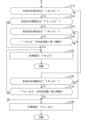
図5のステップS110~ステップS180において、渋滞判定/確定部17は、確定判断部17cで渋滞であるか、渋滞でないかの確定判断を行う。図7は、ステップS110~ステップS180において処理を行う条件と、その処理内容を示す図である。
In steps S110 to S180 in FIG. 5, the congestion determination/
ステップS110において、確定判断部17cは、今回の渋滞判定が"TRUE"か否かを判定する。確定判断部17cは、直近の統合渋滞判定が"TRUE"である場合にステップS110を肯定判定してステップS120へ進み、直近の統合渋滞判定が"TRUE"でない場合にはステップS110を否定判定してステップS160へ進む。上記判定は、左レーン50および右レーン70に分けて行うものとする。
In step S110, the
ステップS120において、確定判断部17cは、前回の渋滞確定が"FALSE"か否かを判定する。確定判断部17cは、直近の渋滞確定判断(後述のステップS180で行われる)が"FALSE"である場合にステップS120を肯定判定してステップS130へ進み、直近の渋滞確定判断(後述のステップS150で行われる)が"FALSE"でない場合にはステップS120を否定判定してステップS150へ進む。上記判定は、左レーン50および右レーン70に分けて行うものとする。
In step S120, the
ステップS130において、確定判断部17cは、前回の渋滞判定が"TRUE"か否かを判定する。確定判断部17cは、前回の統合渋滞判定が"TRUE"である場合にステップS130を肯定判定してステップS140へ進み、前回の統合渋滞判定が"TRUE"でない場合にはステップS130を否定判定してステップS180へ進む。上記判定は、左レーン50および右レーン70に分けて行うものとする。
In step S130, the
ステップS140において、確定判断部17cは、渋滞判定"TRUE"の判定回数を第1閾値と比較する。確定判断部17cは、連続する"TRUE"の判定回数>第1閾値が成立する場合にステップS140を肯定判定してステップS150へ進み、連続する"TRUE"の判定回数>第1閾値が成立しない場合にはステップS140を否定判定してステップS180へ進む。ステップS150へ進む場合は、渋滞判定"TRUE"の判定回数をカウントするカウンタを初期値0に戻す。ステップS180へ進む場合は、渋滞判定"TRUE"の判定回数をカウントするカウンタを+1進める。
In step S140, the
連続する"TRUE"の判定回数>第1閾値が成立する場合とは、図4および図5による処理を所定の周期で繰返す場合に、統合渋滞判定による渋滞であるとの仮判定が所定時間(=第1閾値×所定の周期)よりも長く継続される場合に対応する。
上記判定は、左レーン50および右レーン70に分けて行うものとする。
The case where the number of consecutive "TRUE" judgments > the first threshold value is established corresponds to the case where, when the processing in Figures 4 and 5 is repeated at a predetermined period, the provisional judgment that there is a traffic jam based on the integrated traffic jam judgment continues for longer than a predetermined time (= first threshold value x predetermined period).
The above determination is made separately for the
ステップS150において、確定判断部17cは、渋滞であると渋滞確定判断をして図5による処理を終了する。「TRUE」は、渋滞であると確定判断したことを示す。
上記確定判断は、左レーン50および右レーン70に分けて行うものとする。
In step S150, the
The above-mentioned determination is made separately for the
上述したステップS110を否定判定して進むステップS160において、確定判断部17cは、前回の渋滞確定が"TRUE"か否かを判定する。確定判断部17cは、直近の渋滞確定判断(上記ステップS150で行われる)が"TRUE"である場合にステップS160を肯定判定してステップS170へ進み、直近の渋滞確定判断(後述のステップS180で行われる)が"TRUE"でない場合にはステップS160を否定判定してステップS180へ進む。上記判定は、左レーン50および右レーン70に分けて行うものとする。
In step S160, which is reached after making a negative judgment at step S110 described above, the
ステップS170において、確定判断部17cは、渋滞判定"FALSE"の判定回数を第2閾値と比較する。確定判断部17cは、連続する"FALSE"の判定回数>第2閾値が成立する場合にステップS170を肯定判定してステップS180へ進み、連続する"FALSE"の判定回数>第2閾値が成立しない場合にはステップS170を否定判定してステップS150へ進む。ステップS180へ進む場合は、渋滞判定"FALSE"の判定回数をカウントするカウンタを初期値0に戻す。ステップS150へ進む場合は、渋滞判定"FALSE"の判定回数をカウントするカウンタを+1進める。
In step S170, the
連続する"FALSE"の判定回数>第2閾値が成立する場合とは、図4および図5による処理を所定の周期で繰返す場合に、統合渋滞判定による渋滞でないとの仮判定が所定時間(=第2閾値×所定の周期)よりも長く継続される場合に対応する。
なお、第2閾値は、第1閾値よりも大きな値とする。この理由は、第1閾値が過検知を抑制することを目的にするのに対し、第2閾値がヒステリシスを与えることを目的にすることによる。このように構成することにより、渋滞であるとする確定判断と、渋滞でないとする確定判断とが頻?に繰返される現象を防ぐことが可能になる。
上記判定は、左レーン50および右レーン70に分けて行うものとする。
The case where the number of consecutive "FALSE" judgments > the second threshold value is established corresponds to the case where, when the processing in Figures 4 and 5 is repeated at a predetermined period, the provisional judgment that there is no congestion based on the integrated congestion judgment continues for longer than a predetermined time (= second threshold value x predetermined period).
The second threshold is set to a value larger than the first threshold. The reason for this is that the first threshold is intended to suppress overdetection, whereas the second threshold is intended to provide hysteresis. By configuring in this way, it is possible to prevent a phenomenon in which a definite determination that there is a traffic jam and a definite determination that there is no traffic jam are frequently repeated.
The above determination is made separately for the
ステップS180において、確定判断部17cは、渋滞でないと渋滞確定判断をして図5による処理を終了する。「FALSE」は、渋滞でないと確定判断したことを示す。
上記確定判断は、左レーン50および右レーン70に分けて行うものとする。
In step S180, the
The above-mentioned determination is made separately for the
<渋滞であると確定判断されている場合における例外>
上述したように、外界認識部14は、渋滞判定/確定部17の確定判断部17cで渋滞であると確定判断されている場合には、他レーン(左レーン50、右レーン70)で渋滞を構成する車列C(図3)をひと塊として扱う。ひと塊の車列Cの領域(特定領域)に沿う自レーン60と他レーン(左レーン50、右レーン70)との境界付近で新たに検知された物標(車両)については、設定部14aは、制限部14bにより制限されるため、原則として制御用物標として設定しない。
しかしながら、渋滞判定/確定部17の確定判断部17cで渋滞であると確定判断されている場合において、例えば特定領域で検知された物標の角度(進行方向に対する角度)が外部センサ群1を構成する6つのセンサの少なくとも一つで検知されている場合には、例外として制限部14bによる制限が解除される。そのため、設定部14aは、当該物標を制御用物標として設定する。
<Exceptions when it is determined that there is a traffic jam>
As described above, when the
However, when the
具体例をあげると、渋滞の車列Cから抜け出た車両が強引に自レーン60の自車両200の前に割り込む場合に相当する。例外を設けたことにより、割り込みした物標に基づいてブレーキ制御が行われ、自車両200を適切に減速させる制御が可能になる。
As a specific example, this corresponds to a case where a vehicle that has left a jammed line of vehicles C forcibly cuts in front of the
以上説明した実施の形態によれば、以下のような作用効果を奏する。
(1)実施の形態に係る車両用制御装置30を有する車両制御システム100は、自車両200の周囲の外界を撮像して物標の位置情報を取得するカメラ1aと、カメラ1aの撮像領域内における検出対象からの反射波に基づいて物標の位置情報を取得する第1検出器1b-1~第5検出器1b-5と、カメラ1aおよび第1検出器1b-1~第5検出器1b-5でそれぞれ取得された位置情報に基づいて、自車両200の走行制御に用いる制御用物標を設定する設定部14aと、カメラ1aおよび第1検出器1b-1~第5検出器1b-5でそれぞれ取得された位置情報に基づいて、自車両200が走行する自レーン60に隣接する他レーンとしての左レーン50および右レーン70の渋滞状態を判断する判断部としての渋滞判定/確定部17と、渋滞判定/確定部17で左レーン50および/または右レーン70が渋滞であると判断されている場合に、渋滞を構成する車列Cに沿った左レーン50および/または右レーン70と自レーン60との境界を含む特定領域で、設定部14aが制御用物標を新規に設定することを制限する制限部14bとを備える。
このように構成したので、渋滞時にオクルージョンがもたらす影響を抑制することが可能になる。例えば、渋滞を構成するひと塊の車列Cの一部車両が車列Cの別の車両で一時的に隠されるオクルージョンが発生し、隠された車両が再び現れた場合に、この車両を新たな制御用物標に設定することが制限される。換言すると、渋滞の車列Cの一部を新たな物標として過検知することが抑制される。この結果として、自車両200が走行する自レーン60に渋滞が生じていないにもかかわらず、過検知により生成された制御用物標に基づいて自車両200にブレーキ制御が行われることが防止される。
According to the embodiment described above, the following advantageous effects are achieved.
(1) A
With this configuration, it is possible to suppress the effects of occlusion during congestion. For example, when occlusion occurs in which a part of a group of vehicles C that constitutes a congestion is temporarily hidden by another vehicle in the traffic line C, and the hidden vehicle reappears, setting this vehicle as a new control target is restricted. In other words, overdetection of a part of the traffic line C in the congestion as a new target is suppressed. As a result, braking control of the
(2)車両用制御装置30において、カメラ1aおよび第1検出器1b-1~第5検出器1b-5は、それぞれ所定の周期で位置情報の取得を繰返し、判断部としての渋滞判定/確定部17は、カメラ1aおよび第1検出器1b-1~第5検出器1b-5でそれぞれ取得された直近の位置情報に基づいて他レーンとしての左レーン50および右レーン70の渋滞状態の判断を繰返す。
このように構成したので、渋滞判定/確定部17は、新しい位置情報に基づいて適切に左レーン50および右レーン70の渋滞状態の判断を繰返すことが可能になる。
(2) In the
With this configuration, the congestion judgment/
(3)車両用制御装置30において、判断部としての渋滞判定/確定部17は、カメラ1aの撮像領域R1aにおける他レーンとしての左レーン50および右レーン70の渋滞の可能性の有無と、第1検出器1b-1~第5検出器1b-5による検出範囲R1b-1~R1b-5における左レーン50および右レーン70の渋滞の可能性の有無と、をそれぞれ判定するセンサ別判定部17aと、センサ別判定部17aでカメラ1aの撮像領域R1aにおいて左レーン50、および/または右レーン70の渋滞の可能性ありが判定され、かつ、検出器の検出範囲R1b-1~R1b-5において左レーン50、および/または右レーン70の渋滞の可能性ありが判定された場合に、左レーン50、および/または右レーン70が渋滞であると仮判定する統合判定部17bと、統合判定部17bで左レーン50、および/または右レーン70が渋滞であるとの仮判定が続く回数が第1閾値を超えると、左レーン50、および/または右レーン70が渋滞であると確定判断する確定判断部17cとを含む。
センサ別判定部17aを有することにより、渋滞の可能性の有無の判定をセンサ別に分けて行わない場合と比べて、判定処理を簡単にすることが可能になる。
また、統合判定部17bを有することにより、カメラ1aの撮像領域R1aのみにおいて渋滞の可能性ありが判定された場合または第1検出器1b-1~第5検出器1b-5の検出範囲R1b-1~R1b-5のみにおいて渋滞の可能性ありが判定された場合に、ただちに左レーン50、および/または右レーン70が渋滞であると仮判定する場合と比べて、渋滞の可能性ありとする判定の信頼性を高めることが可能になる。
さらに、確定判断部17cを有することにより、左レーン50および/または右レーン70が渋滞であるとの1回の仮判定でただちに渋滞であると確定判断する場合と比べて、過検知等を避けて渋滞状態を適切に判断することが可能になる。
(3) In the
By providing the sensor-
In addition, by having the integrated judgment unit 17b, when it is judged that there is a possibility of traffic congestion only in the imaging area R1a of the
Furthermore, by having the
(4)車両用制御装置30において、統合判定部17bは、センサ別判定部17aでカメラ1aの撮像領域R1aにおいて左レーン50、および/または右レーン70の渋滞の可能性なしが判定される、または、第1検出器1b-1~第5検出器1b-5の検出範囲R1b-1~R1b-5において左レーン50、および/または右レーン70の渋滞の可能性なしが判定される場合に、左レーン50、および/または右レーン70が渋滞でないと仮判定し、確定判断部17cは、左レーン50および/または右レーン70が渋滞であるとの確定判断の後に、左レーン50および/または右レーン70が渋滞でないとの仮判定が続く回数が第2閾値を超えると、左レーン50および/または右レーン70が渋滞でないと確定判断する。
このように構成したので、左レーン50および/または右レーン70が渋滞でないとの1回の仮判定でただちに渋滞でないと確定判断する場合と比べて、過検知等を避けて渋滞状態を適切に判断することが可能になる。
(4) In the
With this configuration, it is possible to appropriately judge the congestion state while avoiding overdetection, etc., compared to a case where a definitive judgment is immediately made that the
(5)車両用制御装置30において、第2閾値は第1閾値よりも大きい。
このように構成したので、渋滞であるとする確定判断と、渋滞でないとする確定判断とが頻繁に繰返される現象を防ぐことが可能になる。
(5) In the
With this configuration, it is possible to prevent a phenomenon in which a definite judgment that there is a traffic jam and a definite judgment that there is no traffic jam are frequently repeated.
上記実施の形態は、種々の形態に変形することができる。以下、変形例について説明する。
(変形例1)
上述した実施の形態では、カメラ1aが全方位カメラで構成される場合を例示したが、必ずしも全方位カメラでなくてもよい。例えば、自車両200の前方空間を撮像する第1カメラ1a-1、自車両200の左右の側方空間をそれぞれ撮像する第2カメラ1a-2、第3カメラ1a-3、および後方空間を撮像する第4カメラ1a-4でそれぞれ撮像した4つのカメラ画像を取得する構成にしてもよい。4つのカメラ画像をつなぎ合わせると、全方位の空間のカメラ画像に相当する。
The above embodiment can be modified in various ways, and modifications will be described below.
(Variation 1)
In the above embodiment, the
(変形例2)
上記実施の形態では、レーダやライダを第1検出器1b-1~第5検出器1b-5として用いる場合を例示したが、カメラ1aの撮像領域R1aにおける検出対象からの反射波に基づき物標の位置情報を取得するように構成されるものであれば、検出器の構成はいかなるものでもよい。
(Variation 2)
In the above embodiment, examples have been given of using radar or lidar as the
以上の説明はあくまで一例であり、本発明の特徴を損なわない限り、上述した実施の形態および変形例により本発明が限定されるものではない。上記実施の形態と変形例を任意に組合せることも可能である。 The above description is merely an example, and the present invention is not limited to the above-mentioned embodiment and modifications, as long as the characteristics of the present invention are not impaired. The above-mentioned embodiment and modifications can be combined in any manner.
1a カメラ、1b-1~1b-5 第1~第5検出器、10 コントローラ、14 外界認識部、14a 設定部、14b 制限部、16 走行制御部、17 渋滞判定/確定部、17a センサ別判定部、17b 統合判定部、17c 確定判断部、30 車両用制御装置、AC アクチュエータ
1a camera, 1b-1 to 1b-5
Claims (6)
前記カメラの撮像領域内における検出対象からの反射波に基づいて物標の位置情報を取得する検出器と、
前記カメラおよび前記検出器でそれぞれ取得された前記位置情報に基づいて、前記自車両の走行制御に用いる制御用物標を設定する設定部と、
前記カメラおよび前記検出器でそれぞれ取得された前記位置情報に基づいて、前記自車両が走行する自レーンに隣接する他レーンの渋滞状態を判断する判断部と、
前記判断部で前記他レーンが渋滞であると判断されている場合に、前記設定部に対し、前記渋滞を構成する車列に沿った前記他レーンおよび前記自レーンの境界を含む特定領域に新規に設定する前記制御用物標から前記車列を構成する他車両を除外するように制限する制限部と、を備えることを特徴とする車両用制御装置。 A camera that captures an image of the external environment around the vehicle and acquires position information of a target;
a detector that acquires position information of a target based on a reflected wave from a detection object within an imaging area of the camera;
a setting unit that sets a control target to be used for driving control of the host vehicle based on the position information acquired by the camera and the detector, respectively;
a determination unit that determines a congestion state of another lane adjacent to the lane in which the host vehicle is traveling based on the position information acquired by the camera and the detector, respectively;
and a restriction unit that, when the judgment unit determines that the other lane is congested , restricts the setting unit to exclude other vehicles in the traffic jam from the control targets that are newly set in a specific area that includes the boundaries of the other lane and the vehicle's own lane along the traffic jam.
前記検出器は、さらに、前記自レーンに対する前記他車両の割り込みを示す情報を取得し、The detector further acquires information indicating an intrusion of the other vehicle into the own lane,
前記制限部は、前記検出器で前記割り込みを示す情報が取得されると、前記設定部に対する前記制限を解除する、the restriction unit releases the restriction on the setting unit when the detector acquires information indicating the interrupt.
ことを特徴とする車両用制御装置。A vehicle control device comprising:
前記カメラおよび前記検出器は、それぞれ所定の周期で位置情報の取得を繰返し、
前記判断部は、前記カメラおよび前記検出器でそれぞれ取得された直近の前記位置情報に基づいて前記他レーンの渋滞状態の判断を繰返すことを特徴とする車両用制御装置。 3. The vehicle control device according to claim 1,
The camera and the detector each repeatedly acquire position information at a predetermined cycle;
The vehicle control device, wherein the determination unit repeatedly determines the congestion state of the other lane based on the most recent position information acquired by the camera and the detector, respectively.
前記判断部は、
前記カメラの撮像領域における前記他レーンの渋滞の可能性の有無と、前記検出器による検出範囲における前記他レーンの渋滞の可能性の有無と、をそれぞれ判定するセンサ別判定部と、
前記センサ別判定部で前記カメラの撮像領域において前記他レーンの渋滞の可能性ありが判定され、かつ、前記検出器の検出範囲において前記他レーンの渋滞の可能性ありが判定された場合に、前記他レーンが渋滞であると仮判定する統合判定部と、
前記統合判定部で前記他レーンが渋滞であるとの前記仮判定が続く回数が第1閾値を超えると、前記他レーンが渋滞であると確定判断する確定判断部と、を含むことを特徴とする車両用制御装置。 4. The vehicle control device according to claim 3 ,
The determination unit is
a sensor-specific determination unit that determines whether or not there is a possibility of congestion in the other lane in an imaging area of the camera and whether or not there is a possibility of congestion in the other lane in a detection range of the detector;
an integrated determination unit that provisionally determines that the other lane is congested when the sensor-specific determination unit determines that there is a possibility of congestion in the other lane in the imaging area of the camera and determines that there is a possibility of congestion in the other lane in the detection range of the detector; and
A vehicle control device comprising: a confirmation judgment unit that makes a definitive judgment that the other lane is congested when the number of times the integrated judgment unit continues to make the provisional judgment that the other lane is congested exceeds a first threshold value.
前記統合判定部は、前記センサ別判定部で前記カメラの撮像領域において前記他レーンの渋滞の可能性なしが判定される、または、前記検出器の検出範囲において前記他レーンの渋滞の可能性なしが判定される場合に、前記他レーンが渋滞でないと仮判定し、
前記確定判断部は、前記他レーンが渋滞であるとの前記確定判断の後に、前記他レーンが渋滞でないとの仮判定が続く回数が第2閾値を超えると、前記他レーンが渋滞でないと確定判断することを特徴とする車両用制御装置。 5. The vehicle control device according to claim 4 ,
The integrated determination unit provisionally determines that the other lane is not congested when the sensor-specific determination unit determines that there is no possibility of congestion in the other lane in the imaging area of the camera, or determines that there is no possibility of congestion in the other lane in the detection range of the detector,
The vehicle control device is characterized in that the definitive judgment unit makes a definitive judgment that the other lane is not congested when the number of consecutive provisional judgments that the other lane is not congested after the definitive judgment that the other lane is congested exceeds a second threshold value.
前記第2閾値は前記第1閾値よりも大きいことを特徴とする、車両用制御装置。 6. The vehicle control device according to claim 5 ,
The control device for a vehicle, wherein the second threshold value is greater than the first threshold value.
Priority Applications (2)
| Application Number | Priority Date | Filing Date | Title |
|---|---|---|---|
| JP2021201544A JP7589134B2 (en) | 2021-12-13 | 2021-12-13 | Vehicle control device |
| CN202211505337.9A CN116264036A (en) | 2021-12-13 | 2022-11-28 | vehicle control device |
Applications Claiming Priority (1)
| Application Number | Priority Date | Filing Date | Title |
|---|---|---|---|
| JP2021201544A JP7589134B2 (en) | 2021-12-13 | 2021-12-13 | Vehicle control device |
Publications (2)
| Publication Number | Publication Date |
|---|---|
| JP2023087256A JP2023087256A (en) | 2023-06-23 |
| JP7589134B2 true JP7589134B2 (en) | 2024-11-25 |
Family
ID=86722956
Family Applications (1)
| Application Number | Title | Priority Date | Filing Date |
|---|---|---|---|
| JP2021201544A Active JP7589134B2 (en) | 2021-12-13 | 2021-12-13 | Vehicle control device |
Country Status (2)
| Country | Link |
|---|---|
| JP (1) | JP7589134B2 (en) |
| CN (1) | CN116264036A (en) |
Citations (4)
| Publication number | Priority date | Publication date | Assignee | Title |
|---|---|---|---|---|
| JP2016203745A (en) | 2015-04-20 | 2016-12-08 | トヨタ自動車株式会社 | Vehicle traveling control device |
| JP2018109591A (en) | 2017-01-06 | 2018-07-12 | 三菱自動車工業株式会社 | Automatic operation control device |
| JP2021167121A (en) | 2020-04-09 | 2021-10-21 | 株式会社Soken | Vehicle control device |
| JP2021172107A (en) | 2020-04-17 | 2021-11-01 | 日産自動車株式会社 | Driving support method and driving support device |
Family Cites Families (5)
| Publication number | Priority date | Publication date | Assignee | Title |
|---|---|---|---|---|
| JP5185663B2 (en) * | 2008-03-12 | 2013-04-17 | 富士重工業株式会社 | Vehicle driving support device |
| CN103413436B (en) * | 2013-06-21 | 2015-05-06 | 中国航天系统工程有限公司 | Road network running condition analysis system based on fuel consumption acquisition |
| JP7043295B2 (en) * | 2018-03-07 | 2022-03-29 | 本田技研工業株式会社 | Vehicle control devices, vehicle control methods, and programs |
| JP7170862B2 (en) * | 2019-05-22 | 2022-11-14 | 三菱電機株式会社 | Driving support device and driving support method |
| JP2021009624A (en) * | 2019-07-02 | 2021-01-28 | 本田技研工業株式会社 | Vehicle control devices, vehicle control methods, and programs |
-
2021
- 2021-12-13 JP JP2021201544A patent/JP7589134B2/en active Active
-
2022
- 2022-11-28 CN CN202211505337.9A patent/CN116264036A/en active Pending
Patent Citations (4)
| Publication number | Priority date | Publication date | Assignee | Title |
|---|---|---|---|---|
| JP2016203745A (en) | 2015-04-20 | 2016-12-08 | トヨタ自動車株式会社 | Vehicle traveling control device |
| JP2018109591A (en) | 2017-01-06 | 2018-07-12 | 三菱自動車工業株式会社 | Automatic operation control device |
| JP2021167121A (en) | 2020-04-09 | 2021-10-21 | 株式会社Soken | Vehicle control device |
| JP2021172107A (en) | 2020-04-17 | 2021-11-01 | 日産自動車株式会社 | Driving support method and driving support device |
Also Published As
| Publication number | Publication date |
|---|---|
| CN116264036A (en) | 2023-06-16 |
| JP2023087256A (en) | 2023-06-23 |
Similar Documents
| Publication | Publication Date | Title |
|---|---|---|
| US11130492B2 (en) | Vehicle control device, vehicle control method, and storage medium | |
| JP7165093B2 (en) | vehicle control system | |
| CN113320541B (en) | Vehicle control device, vehicle control method, and storage medium | |
| CN110435646B (en) | A vehicle blind spot target tracking method | |
| CN114973644B (en) | Road information generating device | |
| US12509075B2 (en) | Vehicle control device, vehicle control method, and storage medium | |
| US20240051529A1 (en) | Vehicle control device, vehicle control method, and storage medium | |
| US12371016B2 (en) | Vehicle control device, vehicle control method, and storage medium | |
| CN114987529B (en) | Map generation device | |
| US12097879B2 (en) | Vehicle control device, vehicle control method, and storage medium | |
| JP2022121835A (en) | Distance calculation device and vehicle position estimation device | |
| JP2022123239A (en) | Line recognition device | |
| JP7765321B2 (en) | Road recognition device and driving assistance device | |
| JP7543196B2 (en) | Driving control device | |
| JP2022151012A (en) | map generator | |
| JP7589134B2 (en) | Vehicle control device | |
| US20240326872A1 (en) | Travel control apparatus | |
| JP2025000337A (en) | Map generation apparatus | |
| JP7572868B2 (en) | Driving control device | |
| JP7604267B2 (en) | Map Generator | |
| JP7578496B2 (en) | Vehicle control device | |
| JP7776391B2 (en) | Vehicle detection device | |
| US12447958B2 (en) | Travel control apparatus | |
| JP7707238B2 (en) | Map generating device and map generating system | |
| JP7739206B2 (en) | road recognition device |
Legal Events
| Date | Code | Title | Description |
|---|---|---|---|
| A621 | Written request for application examination |
Free format text: JAPANESE INTERMEDIATE CODE: A621 Effective date: 20231128 |
|
| A977 | Report on retrieval |
Free format text: JAPANESE INTERMEDIATE CODE: A971007 Effective date: 20240815 |
|
| A131 | Notification of reasons for refusal |
Free format text: JAPANESE INTERMEDIATE CODE: A131 Effective date: 20240820 |
|
| A521 | Request for written amendment filed |
Free format text: JAPANESE INTERMEDIATE CODE: A523 Effective date: 20240917 |
|
| TRDD | Decision of grant or rejection written | ||
| A01 | Written decision to grant a patent or to grant a registration (utility model) |
Free format text: JAPANESE INTERMEDIATE CODE: A01 Effective date: 20241112 |
|
| A61 | First payment of annual fees (during grant procedure) |
Free format text: JAPANESE INTERMEDIATE CODE: A61 Effective date: 20241113 |
|
| R150 | Certificate of patent or registration of utility model |
Ref document number: 7589134 Country of ref document: JP Free format text: JAPANESE INTERMEDIATE CODE: R150 |