JP7588972B2 - Imaging system, manufacturing system, control method, article manufacturing method, control program, and recording medium - Google Patents
Imaging system, manufacturing system, control method, article manufacturing method, control program, and recording medium Download PDFInfo
- Publication number
- JP7588972B2 JP7588972B2 JP2020107619A JP2020107619A JP7588972B2 JP 7588972 B2 JP7588972 B2 JP 7588972B2 JP 2020107619 A JP2020107619 A JP 2020107619A JP 2020107619 A JP2020107619 A JP 2020107619A JP 7588972 B2 JP7588972 B2 JP 7588972B2
- Authority
- JP
- Japan
- Prior art keywords
- camera
- image
- cameras
- synchronization
- monocular
- Prior art date
- Legal status (The legal status is an assumption and is not a legal conclusion. Google has not performed a legal analysis and makes no representation as to the accuracy of the status listed.)
- Active
Links
Images


Classifications
-
- H—ELECTRICITY
- H04—ELECTRIC COMMUNICATION TECHNIQUE
- H04N—PICTORIAL COMMUNICATION, e.g. TELEVISION
- H04N17/00—Diagnosis, testing or measuring for television systems or their details
- H04N17/002—Diagnosis, testing or measuring for television systems or their details for television cameras
-
- B—PERFORMING OPERATIONS; TRANSPORTING
- B25—HAND TOOLS; PORTABLE POWER-DRIVEN TOOLS; MANIPULATORS
- B25J—MANIPULATORS; CHAMBERS PROVIDED WITH MANIPULATION DEVICES
- B25J19/00—Accessories fitted to manipulators, e.g. for monitoring, for viewing; Safety devices combined with or specially adapted for use in connection with manipulators
- B25J19/02—Sensing devices
- B25J19/021—Optical sensing devices
- B25J19/023—Optical sensing devices including video camera means
-
- G—PHYSICS
- G01—MEASURING; TESTING
- G01S—RADIO DIRECTION-FINDING; RADIO NAVIGATION; DETERMINING DISTANCE OR VELOCITY BY USE OF RADIO WAVES; LOCATING OR PRESENCE-DETECTING BY USE OF THE REFLECTION OR RERADIATION OF RADIO WAVES; ANALOGOUS ARRANGEMENTS USING OTHER WAVES
- G01S17/00—Systems using the reflection or reradiation of electromagnetic waves other than radio waves, e.g. lidar systems
- G01S17/88—Lidar systems specially adapted for specific applications
- G01S17/89—Lidar systems specially adapted for specific applications for mapping or imaging
-
- H—ELECTRICITY
- H04—ELECTRIC COMMUNICATION TECHNIQUE
- H04N—PICTORIAL COMMUNICATION, e.g. TELEVISION
- H04N13/00—Stereoscopic video systems; Multi-view video systems; Details thereof
- H04N13/20—Image signal generators
- H04N13/204—Image signal generators using stereoscopic image cameras
- H04N13/239—Image signal generators using stereoscopic image cameras using two two-dimensional [2D] image sensors having a relative position equal to or related to the interocular distance
-
- H—ELECTRICITY
- H04—ELECTRIC COMMUNICATION TECHNIQUE
- H04N—PICTORIAL COMMUNICATION, e.g. TELEVISION
- H04N13/00—Stereoscopic video systems; Multi-view video systems; Details thereof
- H04N13/20—Image signal generators
- H04N13/204—Image signal generators using stereoscopic image cameras
- H04N13/254—Image signal generators using stereoscopic image cameras in combination with electromagnetic radiation sources for illuminating objects
-
- H—ELECTRICITY
- H04—ELECTRIC COMMUNICATION TECHNIQUE
- H04N—PICTORIAL COMMUNICATION, e.g. TELEVISION
- H04N13/00—Stereoscopic video systems; Multi-view video systems; Details thereof
- H04N13/20—Image signal generators
- H04N13/271—Image signal generators wherein the generated image signals comprise depth maps or disparity maps
-
- H—ELECTRICITY
- H04—ELECTRIC COMMUNICATION TECHNIQUE
- H04N—PICTORIAL COMMUNICATION, e.g. TELEVISION
- H04N13/00—Stereoscopic video systems; Multi-view video systems; Details thereof
- H04N13/20—Image signal generators
- H04N13/296—Synchronisation thereof; Control thereof
-
- H—ELECTRICITY
- H04—ELECTRIC COMMUNICATION TECHNIQUE
- H04N—PICTORIAL COMMUNICATION, e.g. TELEVISION
- H04N13/00—Stereoscopic video systems; Multi-view video systems; Details thereof
- H04N2013/0074—Stereoscopic image analysis
- H04N2013/0081—Depth or disparity estimation from stereoscopic image signals
Landscapes
- Engineering & Computer Science (AREA)
- Multimedia (AREA)
- Signal Processing (AREA)
- Physics & Mathematics (AREA)
- Electromagnetism (AREA)
- Mechanical Engineering (AREA)
- Robotics (AREA)
- Remote Sensing (AREA)
- Radar, Positioning & Navigation (AREA)
- General Physics & Mathematics (AREA)
- Computer Networks & Wireless Communication (AREA)
- Health & Medical Sciences (AREA)
- Biomedical Technology (AREA)
- General Health & Medical Sciences (AREA)
- Studio Devices (AREA)
- Stereoscopic And Panoramic Photography (AREA)
- Testing, Inspecting, Measuring Of Stereoscopic Televisions And Televisions (AREA)
- Length Measuring Devices By Optical Means (AREA)
Description
本発明は複数のカメラの撮像タイミングを同期させて、前記複数のカメラにより被写体の画像を撮像する撮像方法、撮像システム、そのような撮像方法、撮像システムを利用した製造システム、および物品の製造方法に関する。 The present invention relates to an imaging method and imaging system for capturing images of a subject using multiple cameras by synchronizing the imaging timing of the multiple cameras, a manufacturing system that uses such an imaging method and imaging system, and a method for manufacturing an article.
近年、工業製品などの生産ラインにおいて、人手による組立作業に代わって、ロボット装置などを含む組立生産装置による組立作業が行われている。 In recent years, in production lines for industrial products, assembly work has been replaced by assembly production equipment, including robotic devices.
このような生産システムにおいて、組立作業に必要なワークの計測や検査を行うために、ワークを分布的に2次元ないし3次元計測のためのカメラおよび画像処理装置が用いられることがある。例えば、計測や検査に奥行き方向の情報が必要な場合には、2台以上の複数のカメラによりステレオカメラを構成し、三角測量の原理によって対象物の3次元計測を行う手法が用いられる。この種の3次元計測では、複数のカメラで撮像された複数の画像中の物体位置のカメラ毎の違い(視差)を計算し、この視差を奥行き量に変換することにより3次元情報を取得する。 In such production systems, cameras and image processing devices may be used to measure and inspect the work required for assembly work in a distributed manner in two or three dimensions. For example, when depth information is required for measurement or inspection, a stereo camera is configured using two or more cameras, and a method is used to perform three-dimensional measurement of the target object using the principles of triangulation. In this type of three-dimensional measurement, the difference (parallax) between the positions of objects in multiple images captured by the multiple cameras is calculated, and three-dimensional information is obtained by converting this parallax into a depth amount.
この種の3次元計測では、カメラないしワークが相対移動、あるいは相対的に振動するような状態でワークを精密に計測することがある。このような場合、ステレオカメラを構成する複数のカメラ間で撮像時間ずれが生じると、カメラ間で画像中の物体位置がずれてしまうために、視差が正確に計算できなくなる。その場合、奥行きなどの3次元情報を正確に得ることができない。このため、複数のカメラ間で時間ずれが生じないように、撮像のタイミングを正確に同期させる必要がある。 In this type of 3D measurement, the workpiece may be precisely measured while the camera or workpiece is moving or vibrating relative to one another. In such cases, if there is a time lag in imaging between the multiple cameras that make up the stereo camera, the object position in the images will shift between the cameras, making it impossible to accurately calculate parallax. In that case, 3D information such as depth cannot be obtained accurately. For this reason, it is necessary to precisely synchronize the timing of imaging to prevent time lag between the multiple cameras.
ステレオカメラを構成する複数のカメラ間で撮像のタイミングを合わせるために、従来では、一方のカメラから他方のカメラを制御するための通信手段を備えた構成(特許文献1)が知られている。このような構成により、一方のカメラから他方のカメラへ任意のタイミングで撮像指示を出力でき、カメラ間の撮像の時間差を少なくすることができる。また、ステレオカメラを構成する複数のカメラそれぞれに、撮像時刻を画像と対応付けて記憶する機能を備え、撮像時刻に基づき、計測に用いる一方のカメラと他方のカメラがほぼ同じ時刻に撮像した画像を選択する構成(特許文献2)も知られている。 In order to synchronize the timing of imaging between the multiple cameras that make up a stereo camera, a configuration equipped with a communication means for one camera to control the other cameras (Patent Document 1) is known in the past. With such a configuration, imaging instructions can be output from one camera to the other camera at any timing, and the time difference in imaging between the cameras can be reduced. Also known is a configuration (Patent Document 2) in which each of the multiple cameras that make up the stereo camera has a function for storing the imaging time in association with the image, and an image that is used for measurement and that was captured at approximately the same time by one camera and the other camera is selected based on the imaging time.
特許文献1の構成では、ステレオカメラを構成する複数のカメラそれぞれに、トリガ信号を送受信するための通信手段が必要である。これにより、カメラ部分が大型・高価になり、カメラ間の距離が離れていたりカメラ間の配線が困難であったりする環境ではステレオカメラを構成できない場合がある。
In the configuration of
また、特許文献2の構成では、それぞれのカメラに対して撮像時刻を画像と対応付けて記憶する機能が必要である。これにより、システムが複雑で高価になる他、それぞれのカメラの撮像開始時刻や撮像周期が異なっている場合には、カメラ間の撮像の時間差を正確に合わせることができない問題がある。
The configuration of
本発明は、上記の問題点に鑑み、照明光を利用した簡単安価かつ小型軽量な構成により、ステレオカメラを構成する複数のカメラの撮像タイミングの同期ずれを検出できるようにすることにある。 In consideration of the above problems, the present invention aims to detect misalignment of the image capture timing of multiple cameras that make up a stereo camera using a simple, inexpensive, small, lightweight configuration that uses illumination light.
本開示の第1態様は、撮像システムにおいて、照明装置と、当該照明装置で照明された領域の画像を撮像する第1のカメラおよび第2のカメラと、制御装置と、を備え、前記制御装置は、前記第1および第2のカメラそれぞれで、所定の時間間隔の撮像タイミングで画像を撮像させる際に、前記照明装置を所定の時間間隔の点灯/消灯パターンで照明光を照射するように制御することで、前記第1および第2のカメラに前記撮像タイミングに応じた輝度パターンを含む画像を撮像させ、前記第1のカメラで撮像された画像の前記輝度パターンと、前記第2のカメラで撮像された画像の前記輝度パターンとを用いて、前記第1のカメラと前記第2のカメラの前記撮像タイミングの同期ずれを検出し、検出した前記同期ずれに基づいて、前記第1のカメラまたは前記第2のカメラの初期化または電源OFFを伴う処理で前記第1のカメラまたは前記第2のカメラの前記撮像タイミングを変更して同期合わせを行い、前記照明装置の前記所定の時間間隔は、前記第1および第2のカメラのフレームレートよりも短いことを特徴とする撮像システムである。
本開示の第2態様は、照明装置と、当該照明装置で照明された領域の画像を撮像する第1のカメラおよび第2のカメラと、制御装置と、を有する撮像システムにおける前記制御装置の制御方法であって、前記照明装置を所定の時間間隔の点灯/消灯パターンで照明光を照射するように制御する工程と、前記照明光が照明されている状態で、前記第1および第2のカメラのそれぞれにおいて所定の時間間隔の撮像タイミングで撮像され、前記撮像タイミングに応じた輝度パターンを含む画像を取得する工程と、前記第1のカメラで撮像された画像の前記輝度パターンと、前記第2のカメラで撮像された画像の前記輝度パターンとを用いて、前記第1のカメラと前記第2のカメラの前記撮像タイミングの同期ずれを検出する工程と、検出した前記同期ずれに基づいて、前記第1のカメラまたは前記第2のカメラの初期化または電源OFFを伴う処理で前記第1のカメラまたは前記第2のカメラの前記撮像タイミングを変更して同期合わせを行う工程と、を有し、前記照明装置の前記所定の時間間隔は、前記第1および前記第2のカメラのフレームレートよりも短いことを特徴とする制御方法である。
A first aspect of the present disclosure is an imaging system comprising: an illumination device; a first camera and a second camera that capture an image of an area illuminated by the illumination device; and a control device, wherein the control device controls the illumination device to irradiate illumination light in an on/off pattern at a predetermined time interval when causing each of the first and second cameras to capture an image at an imaging timing of a predetermined time interval, thereby causing the first and second cameras to capture an image including a luminance pattern according to the imaging timing, detects a synchronization deviation between the imaging timing of the first camera and the second camera using the luminance pattern of the image captured by the first camera and the luminance pattern of the image captured by the second camera, and changes the imaging timing of the first camera or the second camera to synchronize them based on the detected synchronization deviation through processing involving initialization or power OFF of the first camera or the second camera, and the predetermined time interval of the illumination device is shorter than a frame rate of the first and second cameras.
A second aspect of the present disclosure is a control method for a control device in an imaging system having a lighting device, a first camera and a second camera that capture an image of an area illuminated by the lighting device , and a control device , the control method comprising the steps of: controlling the lighting device to irradiate illumination light in an on /off pattern at a predetermined time interval; acquiring images captured by each of the first and second cameras at an imaging timing at a predetermined time interval while the illumination light is being applied, the images including a luminance pattern corresponding to the imaging timing; detecting a synchronization deviation between the imaging timing of the first camera and the second camera using the luminance pattern of the image captured by the first camera and the luminance pattern of the image captured by the second camera based on the detected synchronization deviation; and changing the imaging timing of the first camera or the second camera to perform synchronization by processing involving initialization or power OFF of the first camera or the second camera, wherein the predetermined time interval of the lighting device is shorter than a frame rate of the first and second cameras.
上記構成によれば、複数カメラをトリガするための通信手段や撮像タイミング制御手段を必要とせず、照明光を利用した簡単安価かつ小型軽量な構成により、ステレオカメラを構成する複数のカメラの撮像タイミングの同期ずれを検出することができる。 The above configuration does not require communication means or imaging timing control means for triggering the multiple cameras, and can detect misalignment of the imaging timing of the multiple cameras that make up the stereo camera with a simple, inexpensive, compact, and lightweight configuration that uses illumination light.
以下、添付図面を参照して本発明を実施するための形態につき説明する。なお、以下に示す構成はあくまでも一例であり、例えば細部の構成については本発明の趣旨を逸脱しない範囲において当業者が適宜変更することができる。また、本実施形態で取り上げる数値は参考数値の例示に過ぎない。 Below, a description will be given of an embodiment of the present invention with reference to the attached drawings. Note that the configuration shown below is merely an example, and those skilled in the art can appropriately modify the detailed configuration, for example, without departing from the spirit of the present invention. Also, the numerical values used in this embodiment are merely examples of reference values.
<実施形態1>
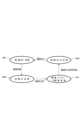
図1(a)は本実施形態における複数カメラを用いてステレオカメラを構成する撮像システムの構成を示している。図1(a)の撮像システムでは、ステレオカメラ1が画像処理装置2に接続されている。ステレオカメラ1と画像処理装置2の接続ケーブルは両者間の通信インターフェースを構成し、電源線、撮像データを送受信するための通信線、通信制御などに用いられるIO線などを含む。これらのうち、この通信インターフェースは、例えば、USB(Universal Serial Bus)のような規格に基づき構成することができる。ステレオカメラ1は、それぞれの撮像光軸を適当な基線長だけ離間させて配置した単眼カメラ101、102を備える。ステレオカメラ1の単眼カメラ101、102で撮像された画像データは、上記の通信インターフェースを介して画像処理装置2に対して伝送することができる。また、ステレオカメラ1の画像処理装置2などから上記の通信インターフェースを介して受信した設定コマンドなどに従い、撮像時の設定情報である撮像パラメータを制御することができる。この撮像パラメータには、露光時間、ゲイン、画像サイズなどが含まれる。また、ステレオカメラ1は、上記の通信インターフェースのIO線を介してステレオカメラ1に、同期ずれ検出のための発光体として設けた、同期ずれ検出照明104~107の発光タイミングを制御することができる。
<
FIG. 1A shows the configuration of an imaging system that uses multiple cameras to configure a stereo camera in this embodiment. In the imaging system of FIG. 1A, a
本実施形態では、ステレオカメラ1は、被写体の3次元情報を計測するために用いられる。例えば、ステレオカメラ1は、ロボット装置、ロボット装置を制御するロボット制御装置のような生産機器とともに物品を製造する生産ラインに配置される。このような構成では、ロボット制御装置がステレオカメラ1によりワークのような被写体を3次元計測した結果に基づき、ロボット装置を制御することができる。なお、本実施例のステレオカメラ1は、複数カメラで構成された撮像システムの構成部材の一例として例示するものに過ぎない。例えば、後述の撮像制御は、何らかの目的で複数のカメラにより同期撮像(同期撮像)を行う任意の撮像システムにおいて実施することができる。例えば、本実施形態の撮像制御を適用可能な複数カメラで構成された撮像システムには、自由視点映像を撮像するための多視点カメラなどが含まれる。
In this embodiment, the
上記のように、図1(a)のステレオカメラ1は、それぞれの撮像光軸を所定の基線長だけ離間して配置された単眼カメラ101、102を備える。本実施形態では、単眼カメラ101、102の前面には照明基板103が配置され、照明基板103には同期ずれ検出照明104~107が設置されている。同期ずれ検出照明104~107は、同一の発光タイミングで単眼カメラ101、102が撮像可能な照明光を照射する照明装置を構成する。
As described above, the
本実施形態では、同期ずれ検出照明104~107は単眼カメラ101、102の共通視野108の外側に配置してある。このような構成では、同期ずれ検出照明104~107によって3次元計測が可能な空間領域である共通視野108の領域が狭められることなく、撮像を行うことができる。
In this embodiment, the synchronization
また、同期ずれ検出照明104、105は単眼カメラ101の個別視野内に、同期ずれ検出照明106、107は単眼カメラ102の個別視野内にそれぞれ配置される。このような構成により、同期ずれ検出照明104~107からの出射光は、単眼カメラ101、102に必ず入射する。
Furthermore, the synchronization
図1(b)は同期ずれ検出照明の配置を示している。同図では図示の上、下方向が、ステレオカメラ1の上部、下部にそれぞれ相当する。同図に示すように、同期ずれ検出照明104、106は単眼カメラ101、102の上部に配置され、同期ずれ検出照明105、107は単眼カメラ101、102の下部に配置されている。同期ずれ検出照明104と106の駆動電源ラインは並列に接続され、両光源は発光タイミングが相互に遅延することなく、同一の発光タイミングで同期して駆動される。同様に、同期ずれ検出照明105と107の駆動電源ラインは並列に接続され、両光源は発光タイミングが相互に遅延することなく、同一の発光タイミングで同期して駆動される。
Figure 1 (b) shows the arrangement of the synchronization error detection illumination. In the figure, the top and bottom directions correspond to the top and bottom of the
照明基板103の前面には3次元計測で用いる照明(不図示)を配置する。この3次元計測用の照明には、測定方式に応じた例えば、パターン投光器などを配置することができる。上記のような構成では、同期ずれ検出照明104~107専用の駆動基板を配置せずに済み、ステレオカメラ1を小型化することができる。
A light (not shown) used for three-dimensional measurement is placed on the front side of the
図1(a)に示す画像処理装置2は演算を行う、例えばCPUないしFPGAと、ROMおよびRAMからなるメモリ部と、外部と通信を行うインターフェース(I/F)部などのハードウェアにより構成することができる。図1(a)では、画像処理装置2は201~205の機能ブロックとして示されている。なお、本実施形態の画像処理装置2は、後述するようにステレオカメラ1の撮像制御機能も含んでおり、概念的には、画像処理を介して撮像制御を行う制御装置と考えてもよい。
The
ここで、図15に図1の画像処理装置2を構成する制御系の具体的なハードウェア構成の一例につき説明しておく。図1に示す画像処理装置2を構成する各機能ブロックは、図15のような構成では、CPU1601とその周辺のハードウェア、ないしCPU1601により実行されるソフトウェアによって実現できる。画像処理ないし撮像制御に用いられる記憶部は、ROM1602、RAM1603、外部記憶装置1606(HDD)などの記憶領域により構成される。
Here, FIG. 15 illustrates an example of a specific hardware configuration of the control system that constitutes the
図15の制御系は、主制御手段としてのCPU1601、記憶装置としてのROM1602、およびRAM1603を備えた構成である。ROM1602には、本実施形態の制御処理手順を実現するためのCPU1601の制御プログラムや定数情報などを格納しておくことができる。また、RAM1603は、その制御手順を実行する時にCPU1601のワークエリアなどとして使用される。また、図15の制御系には、外部記憶装置1606が接続されている。外部記憶装置1606は、本発明の実施には必ずしも必要ではない場合があるが、HDDやSSD、ネットワークマウントされた他のシステムの外部記憶装置などから構成することができる。
The control system of FIG. 15 is configured to include a
本実施形態の制御を実現するためのCPU1601の制御プログラムは、上記の外部記憶装置1606やROM1602の(例えばEEPROM領域)のような記憶部に格納しておく。その場合、本実施形態の制御手順を実現するためのCPU1601の制御プログラムは、ネットワークインターフェース1607を介して、上記の各記憶部に供給し、また新しい(別の)プログラムに更新することができる。あるいは、後述の制御手順を実現するためのCPU1601の制御プログラムは、各種の磁気ディスクや光ディスク、フラッシュメモリなどの記憶手段と、そのためのドライブ装置を経由して、上記の各記憶部に供給し、またその内容を更新することができる。本実施形態の制御手順を実現するためのCPU1601の制御プログラムを格納した状態における各種の記憶手段、記憶部、ないし記憶デバイスは、本発明の制御手順を格納したコンピュータ読み取り可能な記録媒体を構成することになる。
The control program of the
ネットワークインターフェース1607は、例えばIEEE 802.3のような有線通信、IEEE 802.11、802.15のような無線通信による通信規格を用いて構成することができる。このネットワークインターフェース1607、およびネットワーク1608を介して、CPU1601は、他の装置1104と通信することができる。例えばステレオカメラ1がネットワーク接続されるものとすれば、この他の装置1104は、例えばステレオカメラ1に相当する。ステレオカメラ1がネットワーク接続以外の規格によって接続される場合には、インターフェース1605を用いる。インターフェース1605は、他の周辺機器と接続するために用いられるものであってもよい。
The
また、図15の制御系に、必要に応じてユーザインターフェース装置400(UI装置)を設けることができる。ユーザインターフェース装置400は、例えばLCDディスプレイ、キーボード、ポインティングデバイス(マウス、ジョイスティック、ジョグダイヤルなど)などから成るGUI装置などであってもよい。ユーザインターフェース装置400は、撮像した画像や、後述の同期合わせ処理、同カメラによる3次元計測処理の進行状態、結果などをユーザに通知したり、あるいは撮像パラメータや同期合わせに関する制御定数を設定したりするために用いることができる。
In addition, a user interface device 400 (UI device) can be provided in the control system of FIG. 15 as necessary. The
図1(a)に示すように、画像処理装置2は、カメラ制御部201、照明制御部202、同期ずれ量演算部203、同期合わせ制御部204、3次元計測部205の機能ブロックを有している。例えば、これらの制御部(機能ブロック)はFPGA内のハードウェアブロックにより実現してもよく、また、上記のCPU1601が例えばROM1602などに記憶されているプログラムを読み込み実行することによって実現してもよい。
As shown in FIG. 1(a), the
以下、図1(a)の画像処理装置2の各機能ブロック(201~205)の概要につき説明する。カメラ制御部201は、単眼カメラ101、102の撮像動作を制御する。この制御の詳細については、単眼カメラ101、102の内部構成を説明する時に改めて詳述するが、ここでは各部の概要を説明する。
Below, we will provide an overview of each functional block (201 to 205) of the
本実施形態において、撮像を行う場合、最初に、単眼カメラ101、102に電源供給し、カメラ制御部201から初期化指示を送信する。単眼カメラ101、102の初期化が完了したら、単眼カメラ101、102に撮像パラメータの変更指示を送信する。この撮像パラメータには、例えば露光時間、ゲイン、画像サイズ、あるいはさらに光学系によっては焦点距離などのパラメータが含まれる場合もある。
In this embodiment, when capturing an image, first, power is supplied to the
撮像パラメータの調整が完了すると、カメラ制御部201は動画出力開始指示を送信し、単眼カメラ101、102から動画を出力させる。また、この時、照明制御部202が撮像条件に応じて、3次元計測用の照明や、同期ずれ検出照明104~107の駆動条件を決定する。カメラ制御部201は、他機能ブロックからの画像取得指示を受信したら、動画データから静止画を切り取り、静止画データを取得する機能を有する。
When the adjustment of the imaging parameters is complete, the
また、カメラ制御部201が、イメージセンサ302(図2参照)への電源供給を停止すると、動画出力が停止する。その後、上記電源供給、初期化を行うと上記のプロセスを再度実行させることができ、これにより、動画出力を再開することができる。以上のようにして、カメラ制御部201は動画出力開始タイミングを制御する。
When the
照明制御部202は、同期ずれ検出照明104~107の発光タイミングを制御する。この照明制御は、例えば、IO線を介して、同期ずれ検出照明104~107に対してPWM(Pulse Width Modulation)信号を送信することにより行う。上述のように、同期ずれ検出照明104、106の駆動電源ラインは照明基板103内で導通しているため、同期発光が可能である。同様に同期ずれ検出照明105、107も同期発光が可能である。なお、例えば、照明制御部202が点灯/消灯コマンドを出力した場合に実際に対象の照明光源が点灯/消灯するまでの遅延時間はごく短い。例えば、照明光源の駆動制御に対する応答時間は、単眼カメラ101、102の撮像制御時間、例えばこれらカメラの1フレーム時間(例えば1/24秒、1/30秒、1/60秒など)よりも充分、短い。即ち、同期ずれ検出照明104~107の制御速度(制御時間)は、動画の撮像制御速度(制御時間)よりも充分高速(短時間)であるものとする。
The
同期ずれ量演算部203は、単眼カメラ101、102の撮像タイミングの同期ずれ量を演算する。同期ずれ量の算出方法の詳細については後述する。
The synchronization deviation
同期合わせ制御部204は、同期ずれ量演算部203で同期ずれを検出すると、単眼カメラ101、102の撮像タイミングの同期合わせを行う。この同期合わせの詳細については後述する。
When the synchronization deviation
3次元計測部205は、ステレオカメラ1の単眼カメラ101、102で撮像した画像を用いて、3次元計測を行う。単眼カメラ101、102で撮像した画像に対する3次元計測部205は、ステレオマッチング処理から求めた視差量と、ステレオカメラ校正から求めた内部パラメータおよび外部パラメータを用いて三角測量の原理により距離を算出することができる。
The three-
上記のステレオマッチング処理では、例えば、単眼カメラ101の撮像画像を基準画像として、単眼カメラ102の撮像画像内から対応している画素、即ち、被写体の同じ特定部位が撮像されている画素をマッチングにより求める。このステレオマッチング処理としては、例えば、SAD(Sum of Absolute Difference)、SSD(Sum of Squared Difference)などのブロックマッチング法が知られている。このような公知のマッチング処理の手法は、本実施形態でも用いることができる。
In the above stereo matching process, for example, the image captured by the
上記の内部パラメータ、外部パラメータなどは、例えばOpenCVのような(デジタル)カメラに係る画像処理ライブラリで用いられている概念と同等である。内部パラメータは、レンズの焦点距離やひずみ特性などの光学特性を意味し、外部パラメータは、ステレオカメラ内の2つのカメラの相対位置・姿勢を意味する。内部パラメータや外部パラメータは、予め形状が既知な校正チャートを撮像し、最適化手法を用いて算出しておくことができる。単眼カメラ101、102に関して事前に算出しておいた内部パラメータ、外部パラメータは画像処理装置2内の例えばROMに保存しておく。
The above internal parameters, external parameters, etc. are equivalent to the concepts used in image processing libraries related to (digital) cameras, such as OpenCV. The internal parameters refer to optical characteristics such as the focal length and distortion characteristics of the lens, and the external parameters refer to the relative position and orientation of the two cameras in the stereo camera. The internal parameters and external parameters can be calculated in advance by capturing an image of a calibration chart with a known shape and using an optimization method. The internal parameters and external parameters calculated in advance for the
なお、本実施形態では、画像処理装置2はステレオカメラ1と別装置として説明するが、いわゆるスマートカメラのように、画像処理装置2がステレオカメラ1に内蔵されていてもよい。このような構成では、ステレオカメラ1と画像処理装置2の配線が不要になり、システムの設置工数を大幅に削減できる。
In this embodiment, the
次に、単眼カメラ101、102の内部構成について説明する。本実施形態の単眼カメラ101、102は携帯用モジュールカメラ、WEBカメラなどの比較的小型安価なカメラである。本実施形態では、単眼カメラ101、102は、それぞれ単体のユニットとして購入できる製品であり、これらカメラを一体の筐体やフレームに組み込んでステレオカメラ1を構成するものとする。単眼カメラ101、102は、上記の筐体やフレームによって、所定の基線長だけ離間して相互に位置決めされる。本実施形態では、単眼カメラ101、102は、ゲンロック機能などの外部同期信号への同期機能や、撮像時刻を出力するタイムスタンプ機能を必要としない。本実施形態によれば、上記のようにして、入手が容易で比較的安価な単眼カメラ101、102のユニットからステレオカメラ1を構成することができる。
Next, the internal configuration of the
図2は、単眼カメラ101の内部構成の一例を示している。単眼カメラ102の構成も単眼カメラ101と同様であるものとする。この単眼カメラ101は、集光部301とイメージセンサ302、センサ制御部303、画像フォーマット変更部304、電源制御部305が一体化された構造である。
Figure 2 shows an example of the internal configuration of
集光部301はレンズであり、集光した光をイメージセンサ302に入射するための撮像光学系を構成する。
The focusing
イメージセンサ302は例えば、CCD(Charge Coupled Device:電荷結合素子)、CMOS(Complementary Metal Oxide Semiconductor:相補形金属酸化膜半導体)の撮像素子である。センサ制御部303に送信する画像は、例えば、MIPI CSI-2(Mobile Industry Processor Interface Camera Serial Interface -2)に準拠する所謂RAW画像フォーマットとする。ただし、イメージセンサ302の規格や出力画像フォーマットはこれらに限定されることなく、任意であり、当業者が自由に選択することができる。
The
ここで、単眼カメラ101の上記の機能ブロック(303~305)の概要について説明する。センサ制御部303と、画像フォーマット変更部304、電源制御部305は、FPGAと、ROMおよびRAMからなるメモリ部と、外部と通信を行うインターフェース(I/F)部を有している電子回路である。これらの各ブロックおよび、イメージセンサ302は単眼カメラ101内部で相互に電気的に接続される。
Here, we will provide an overview of the above-mentioned functional blocks (303 to 305) of the
センサ制御部303は、画像処理装置2内のカメラ制御部201と通信し、イメージセンサ302の状態遷移を制御する。ここで、図3に本実施形態のイメージセンサ302の動作状態の遷移を示す。図3に示すように、イメージセンサ302の動作状態は、電源OFF状態401、初期化状態402、撮像パラメータ調整状態403、動画出力状態404の4つの状態を有する。これらの各状態は次のようなものである。
The
電源OFF状態401は、イメージセンサ302に電源が供給されていない状態である。センサ制御部303は、画像処理装置2内のカメラ制御部201からの電源供給指示を受信すると、イメージセンサ302に電源を供給する。イメージセンサ302に電源が供給されると、イメージセンサ302は初期化状態402に遷移する。
The power OFF
初期化状態402は、イメージセンサ302の初期化を行っている状態である。まず、センサ制御部303がイメージセンサ302にクロック信号を供給する。センサ制御部303は、画像処理装置2内のカメラ制御部201からの初期化開始指示を受信したら、イメージセンサ302に初期化信号を送信する。このようにして初期化が完了すると、センサ制御部303とイメージセンサ302間で通信を行えるようになり、撮像パラメータ調整状態403に遷移する。
The
また、撮像パラメータ調整状態403は、センサ制御部303がイメージセンサ302の撮像パラメータを調整可能な状態である。撮像パラメータは、例えば、露光時間、ゲイン、画像サイズ等である。この状態において、センサ制御部303が画像処理装置2のカメラ制御部201から、上記の撮像パラメータ変更指示を受信すると、イメージセンサ302に対して例えば制御コマンドを送り、撮像パラメータが格納されているレジスタ値を書き換える。
The imaging
センサ制御部303は、画像処理装置2のカメラ制御部201から動画出力開始指示を受信すると、イメージセンサ302に対して動画出力開始信号を送信し、動画出力状態404に遷移させる。
When the
図3の動画出力状態404は、イメージセンサ302が動画データを画像フォーマット変更部304に対して、出力し続けている状態である。この状態において、センサ制御部303が画像処理装置2内のカメラ制御部201から動画出力停止指示を受信すると、イメージセンサ302への電源供給を停止し、動画出力を停止させる。これにより、本実施形態のイメージセンサ302は電源OFF状態401に遷移する。
The
図3の電源OFF状態401に単眼カメラ101(102も同様)が遷移した後は、画像処理装置2内のカメラ制御部201がセンサ制御部303を介して上記のイメージセンサ302の再度状態遷移を行わせることにより、動画の再出力が可能となる。以上のように、画像処理装置2は、単眼カメラ101、102の動画出力開始(あるいは終了)タイミングを制御することができる。
After the monocular camera 101 (and likewise 102) transitions to the
なお、以上では、単眼カメラ101(102も同様)が動画出力状態404から、電源OFF状態401にしか遷移できない構成について説明した。しかしながら、イメージセンサ302が動画出力状態404から初期化状態402への状態遷移機能を有している場合には、単眼カメラ101(102も同様)を動画出力状態404から初期化状態402へ状態遷移させることができる。このような状態遷移機能がイメージセンサ302に実装されている場合には、電源オフを経由しなくても、例えば単眼カメラ101、102の同期合せのために動画出力タイミングを変更できる可能性がある。
The above describes a configuration in which the monocular camera 101 (as well as 102) can only transition from the
また、単眼カメラ101(102も同様)のイメージセンサ302が、撮像モード変更機能として、動画モードにした場合に動画出力開始し、静止画モードにしたら動画出力を停止する機能を有するような構成も考えられる。このようなカメラ構成では、撮像モードを動画モードと静止画モードの間で切り換えることにより、電源オフを経由しなくても、例えば単眼カメラ101、102の同期合せのために動画出力タイミングを変更できる可能性がある。
It is also possible to configure the
本実施形態では主に、単眼カメラ101、102を動画出力状態404から電源OFF状態401へ切り換えることにより、リセットし、両カメラの同期合せのために動画出力開始タイミングを変更する制御につき説明する。しかしながら、上記のような他の状態遷移機能や、撮像モード切り換えを行うことにより、例えば単眼カメラ101、102の同期合せのために動画出力タイミングを変更してもよい。
In this embodiment, the
図2において、イメージセンサ302とセンサ制御部303間の制御インターフェースは、例えば、IO端子とI2C(Inter-Integrated Circuit)によって構成することができる。また、本実施形態の画像フォーマット変更部304は、イメージセンサ302から受信したRAW画像フォーマットを、画像処理装置2に送信するための画像フォーマットに変更する機能を有している。ここで画像フォーマット変更部304がサポートする画像フォーマットは、例えばUVC(USB Video Class)に準拠しているフォーマットなどである。ただし、画像フォーマット変更部304がUVC以外の他の画像フォーマットをサポートしていても構わない。
In FIG. 2, the control interface between the
また、電源制御部305は、画像処理装置2から電源供給の指令を受信すると、センサ制御部303と画像フォーマット変更部304に電源を供給する機能を有する。この電源供給の指令により、単眼カメラ101、102の状態を電源OFF状態401から初期化状態402に移行させることができる。イメージセンサ302への電源供給は、上記のようにセンサ制御部303を介して制御される。
The power
(同期ずれ量の算出方法)
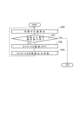
ここで、本実施形態において、ステレオカメラの単眼カメラ101、102の同期ずれ量の算出手法につき説明する。図4は同期ずれの検出手順を、図5は単眼カメラ101、102から出力された画像の一例を経時的に示している。
(Method of calculating the amount of synchronization deviation)
Here, a description will be given of a method for calculating the amount of synchronization deviation between the
図4のステップS10からS15までは、本実施形態における同期ずれ検出のための発光撮像工程に、ステップS16は本実施形態における同期ずれ検出のための画像処理工程に相当する。 Steps S10 to S15 in FIG. 4 correspond to the light emission imaging process for detecting synchronization deviation in this embodiment, and step S16 corresponds to the image processing process for detecting synchronization deviation in this embodiment.
図4のステップS10では、画像処理装置2のカメラ制御部201から送信された動画出力開始指示に基づき、センサ制御部303が単眼カメラ101を動画出力状態404に遷移させる。続いて、同期ずれ量演算部203はカメラ制御部201に単眼カメラ101の動画出力開始指示を送るように指示する。これにより任意のタイミングで単眼カメラ101で撮像された画像を取得できるようになる。
In step S10 of FIG. 4, the
ステップS11では、画像処理装置2のカメラ制御部201から送信された動画出力開始指示に基づき、センサ制御部303が単眼カメラ102を動画出力状態404に遷移させる。続いて、同期ずれ量演算部203はカメラ制御部201に単眼カメラ102の動画出力開始指示を送るように指示する。これにより任意のタイミングで単眼カメラ102で撮像された画像を取得できるようになる。
In step S11, the
ステップS12では、同期ずれ検出照明104~107の制御を開始する。上述のように、同期ずれ検出照明104~107を点灯/消灯させる制御は、単眼カメラ101および102で出力される動画のフレームレートよりも高速に実行されることが望ましい。ただし、本実施形態では、説明の簡単化のため、フレームレートと照明の点灯/消灯制御の周期が等しい場合について説明する。まず、ステップS12では、同期ずれ量演算部203は照明制御部202に指令し、一定時間Δt[ms]後に同期ずれ検出照明104と106を同時に点灯させる。次に、同様にして一定時間Δt[ms]後に同期ずれ検出照明105と107を同時に点灯させる。次に、同様にして一定時間Δt[ms]後に同期ずれ検出照明104と106を同時に点灯させる。次に、同様にして一定時間Δt[ms]後に同期ずれ検出照明105と107を同時に点灯させる。このように同期ずれ検出照明104と106、105と107を交互に一定時間Δt[ms]のインターバルで点灯させる処理は、ステップS13、S14で単眼カメラ101、102の画像を取得する処理の間、ステップS15まで繰り返し行う。
In step S12, control of the synchronization
ステップS13では単眼カメラ101の画像を取得する。この時、同期ずれ量演算部203は、カメラ制御部201に画像取得指示を送り、単眼カメラ101から送信される動画データから静止画を切り取り、その静止画データを取得する。ステップS14では単眼カメラ102の画像を取得する。この時、同期ずれ量演算部203は、カメラ制御部201に画像取得指示を送り、単眼カメラ102から送信される動画データから静止画を切り取り、その静止画データを取得する。
In step S13, an image from the
ステップS15では、同期ずれ量演算部203は照明制御部202に指令し、同期ずれ検出照明104~107を消灯する。続いて、ステップS16において、例えば以下のようにしてステップS13とステップS14で得られた画像から同期ずれ量を算出する。
In step S15, the synchronization deviation
図5において、601A~606Aは各時刻における単眼カメラ101から出力された画像を示している。同図では、時刻t1から一定の時間Δt経過したときの時刻をt2、t3、t4…と示している。即ち、時刻t2はt1+Δt、時刻t3はt2+Δt、時刻t4はt3+Δtである。
In FIG. 5, 601A to 606A show images output from the
図5において、601Aは時刻t1における同期ずれ検出照明104と106が点灯中に撮像された画像である。602Aは時刻t2における同期ずれ検出照明104~107が点灯中に撮像された画像である。603Aは時刻t3における同期ずれ検出照明105と107が点灯中に撮像された画像である。604Aは時刻t4における同期ずれ検出照明104~107が消灯中に撮像された画像である。この後の時刻の画像605A、606A…は601A~602Aと同じような画像が繰り返し出力される。一方、601B~606Bも単眼カメラ101と同様に各時刻における単眼カメラ102から出力された画像である。
In FIG. 5, 601A is an image captured at time t1 while the synchronization
同期ずれ検出照明104~107は、時刻t12で同期ずれ検出照明104~107すべてが点灯し、時刻t23で同期ずれ検出照明105と107だけが点灯する。さらに、時刻t34で同期ずれ検出照明104~107すべてが消灯し、時刻t45で同期ずれ検出照明104と106だけが点灯する動作が続き、このような照明パターンが繰り返されている。この例では、各照明の時刻t12、t23、t34、t45の間隔もΔtであり、時刻t1と時刻t12の差はΔt/2とする。
At time t12, all of the synchronization
例えば、ここで、ステップS13とステップS14で得られた画像が時刻t3で得られる603Aと603Bの画像であるとする。この場合、実際に603Aが撮像された時刻は時刻t23から時刻t34までの間で、603Bが撮像された時刻はt12から時刻t23までの間である。この例では、検出された単眼カメラ101、102の同期ずれ量はΔt以下である。そのため、例えば、同等の画像パターン(輝度パターン)を両カメラで撮像した画像から検索する画像処理を介して、単眼カメラ101、102の同期ずれ量を算出することができる。
For example, assume that the images obtained in steps S13 and S14 are images of 603A and 603B obtained at time t3. In this case, 603A was actually captured between time t23 and time t34, and 603B was captured between time t12 and time t23. In this example, the detected amount of synchronization deviation between
本実施の形態では、検出照明104~107の点灯・消灯を切り換える間隔Δtと、撮影間隔Δtが等しい場合について説明した。照明の切り換え間隔をより短くすると、より高精度に同期ずれを検出することができる。例えば、照明の切り替え時間をΔt/2とすると、Δt以下の分解能で同期ずれ量を検出することができる。
In this embodiment, a case has been described in which the interval Δt for switching on and off the
ただし、照明の切り替え時間が高速すぎると、正しく同期ずれを検出できない場合がある。例えば、本実施の形態のように、上下ОN、上のみОN、下のみОN、上下ОFFの4段階で照明点灯・消灯を切り替える場合について説明する。その場合はΔt/4よりも早い周期で切り替えると、同期ずれ量がΔtあった場合に、単眼カメラ101と102で同じ照明条件下の画像が撮影されてしまうためである。このように、照明切り替え時間は、撮影間隔Δtを、照明条件の段階数で割った時間よりも長い時間が望ましい。
However, if the lighting switching time is too fast, it may not be possible to correctly detect synchronization errors. For example, as in this embodiment, a case will be described in which the lighting is switched on and off in four stages: top and bottom ON, top only ON, bottom only ON, and top and bottom OFF. In this case, if the switching is performed at a cycle faster than Δt/4,
なお、同期ずれ検出照明104~107の点灯・消灯を切り換える間隔Δtは、予め実測して求めてもよい。例えば、同期ずれ量算出の前に、単眼カメラ101と102を動画出力状態にした後に、一度だけ同期ずれ検出照明104~107を点灯する。そして、単眼カメラ101、102から出力された画像が604Aのように消灯している画像から、602Aのように点灯している画像に変わる時刻の差に基づき決定してもよい。
The interval Δt for switching on and off the synchronization
また、通常、撮像画像の周辺部分は、歪みが大きく3次元計測などの画像処理に使用しない場合が多い。また、単眼カメラ101と102の共通視野でない部分は、後の3次元計測では使用しない。即ち、本実施形態では同期ずれ検出照明104~107が上述の画像処理に使用しない部分のみに影響を与えるように配置している。このため、上記のような照明制御であれば、後の3次元計測中も同期ずれを常に検出できる。
Also, typically, the peripheral parts of a captured image are highly distorted and are often not used for image processing such as 3D measurement. Also, parts that are not in the common field of view of the
また、本実施形態では、同期ずれ検出照明104~107は4つ用いたが、単眼カメラ101、102に同時に影響を与えるような場所に同期ずれ検出照明を配置すれば、同期ずれ検出照明は1つだけ配置する構成でもよい。逆に、同期ずれ検出照明の発光態様、例えば、発光色や発光パターンを異ならせ、個々の同期ずれ検出照明を識別できるような構成としてもよい。この場合、例えば撮像されている画像から点灯している同期ずれ検出照明を判別できる。このことを利用して、例えば同期ずれ検出照明の数をもっと増やしてもよい。このような構成によって、より高精度に同期ずれ量を算出できる可能性がある。
In addition, in this embodiment, four synchronization
(同期合わせ)
ここで図6を参照して、上記のようにして検出した同期ずれ量に基づき、単眼カメラ101、102を同期合わせする手法の一例につき説明する。図6は、同期合わせの手順を示している。
(Synchronization)
An example of a method for synchronizing the
図6のステップS20では、上述のようにして同期ずれ量を算出する。ステップS21では、算出した同期ずれ量が規定値以内かを判定する。もし算出した同期ずれ量が規定値以内であるならば(ステップS21のYES)、図6の処理に続き、3次元計測処理を行う。また、規定値以上であるならば(ステップS21のNO)、ステップS22に進む。 In step S20 of FIG. 6, the amount of synchronization deviation is calculated as described above. In step S21, it is determined whether the calculated amount of synchronization deviation is within a specified value. If the calculated amount of synchronization deviation is within the specified value (YES in step S21), the process of FIG. 6 is continued, and three-dimensional measurement processing is performed. If the amount of synchronization deviation is equal to or greater than the specified value (NO in step S21), the process proceeds to step S22.
ステップS22では、同期合せのための処理として、単眼カメラ102の電源をOFFにする。この同期合せ制御は、図3に示すような単眼カメラ101、102の状態遷移態様を利用したものである。
In step S22, the power supply of the
ステップS22に続き、ステップS23では、同期ずれしている単眼カメラのうち1つ、例えば、単眼カメラ102を動画出力状態404(図3)にする。これにより、単眼カメラ102は、図3で説明したように、電源OFF状態401からは初期化状態402、撮像パラメータ調整状態403を経て動画出力状態404に移行する。ステップS23の後、処理はステップS20に進む。この時、単眼カメラ102が動画出力状態404になるまでの時間は、ある程度ランダムな過程により定まるものとする。従って、複数回、上記のステップS20~S23の処理を繰り返すことによって、いずれ同期ずれ量が規定値以内となる。
Following step S22, in step S23, one of the out-of-sync monocular cameras, for example,
以上のように、本実施形態では、同期ずれ検出照明を所定のインターバルで点灯駆動するパターン、即ち照明光パターンを利用して、単眼カメラ101、102により撮像された画像中の輝度パターンを介して、両カメラの同期ずれ量を検出することができる。そして、同期ずれ量が規定値を超えている場合に、単眼カメラ101、102の一方を電源OFFし、初期化することにより、比較的ランダムな過程を利用して、両者の同期合わせを行う。
As described above, in this embodiment, the amount of synchronization deviation between the two cameras can be detected through the brightness pattern in the images captured by the
本実施形態では、同期ずれ検出照明104~107が3次元計測に影響を与えない位置に配置してあるため、同期ずれ検出は3次元計測中の時間帯にも実行できる。そして、上記の同期合わせ処理は、例えば、ステレオカメラ1が計測処理を行っていない時間帯を利用して行うことができる。本実施形態では、このような制御により、3次元計測の計測時間を延長することなしにステレオカメラ1を構成する単眼カメラ101、102の同期合わせが可能である。
In this embodiment, since the synchronization
<実施形態2>
上述した実施形態1では、同期ずれ検出照明104~107をステレオカメラ1に内蔵している。しかしながら、ステレオカメラ1の構成をより簡単安価、小型軽量にするには、本実施形態のように外部照明を用いて同期ずれ検出を行う構成も考えられる。
<
In the above-described first embodiment, the synchronization out-of-
以下では、実施形態1とは異なるハードウェアや制御系の構成の部分について図示、説明し、実施形態1と同様の部分については上記と同様の構成、作用が可能であるものとし、その詳細な説明については省略する。
Below, only the hardware and control system configurations that differ from those of
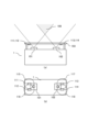
本実施形態では、図7に示すように、外部照明130は単眼カメラ101および単眼カメラ102の共通視野108内に配置する。本実施形態では、この外部照明130を同期ずれ検出照明として用いる。外部照明130は同期ずれ検出の専用照明であってもよく、また、他の画像処理等の用途に使用する照明であってもよい。
In this embodiment, as shown in FIG. 7, the
また、本実施形態でも、単眼カメラ101、102の動画撮像制御における1フレーム時間(例えば1/24秒、1/30秒、1/60秒など)よりも充分短いものとする。即ち、同期ずれ検出照明104~107の制御速度(制御時間)は、動画の撮像制御速度(制御時間)よりも充分高速(短時間)である。本実施形態においても、同期ずれ検出と同期合せに関する制御手順は、図4、図6で説明したものとほぼ同じである。
In this embodiment, the control speed (control time) of the synchronization out-of-sync detection lights 104-107 is also sufficiently shorter than the one frame time (e.g., 1/24 seconds, 1/30 seconds, 1/60 seconds, etc.) in the video capture control of the
ただし、単眼カメラ101、102がローリングシャッターである場合と、グローバルシャッターである場合とで、同期検出ずれの手法が多少異なるものとなる。以下図8(a)~(c)を参照して本実施形態の同期検出ずれ方法を説明する。
However, the method for detecting synchronous deviation differs slightly depending on whether the
図8(a)は、単眼カメラ101および102がローリングシャッターである場合に外部照明130を用いて撮像される画像の一例を示している。図8(b)は、図8(a)のような状況で撮像される画像の高さ方向に関する輝度値の平均値の一例を示したグラフである。
Figure 8(a) shows an example of an image captured using
上記のように、同期ずれ検出制御は実施形態1とほぼ同様に行うことができる(図4)。図4のステップS12では、外部照明130を一定時間点灯する。この一定時間の点灯は単眼カメラ101、102の1フレーム時間に対して短く。点灯指令後、外部照明130は一定時間の後、消灯し、本実施形態の場合、図4のステップS15は必要ない。
As described above, synchronization deviation detection control can be performed in a manner similar to that of the first embodiment (FIG. 4). In step S12 of FIG. 4, the
ステップS13では、単眼カメラ101の画像を取得する。取得された画像は701Aのような画像となる(図8(a))。続いて、ステップS14では、単眼カメラ102の画像を取得する。取得された画像は701Bのような画像となる(図8(a))。外部照明130の光は、単眼カメラ101、102のローリングシャッターである場合、図8(a)のようにライン状に撮像される。ローリングシャッターでは、カメラの各画素(ないし各撮像ライン)の露光が順次オンとなるためである。
In step S13, an image is acquired from the
ステップS16では、図8(a)のように撮像された画像から、次のようにして同期ずれ量を算出する。ここでは、例えば、単眼カメラ101、102のフレームレート(FPS)をF、画像サイズの高さをH、幅をWとする。
In step S16, the amount of synchronization deviation is calculated from the image captured as shown in FIG. 8(a) as follows. Here, for example, the frame rate (FPS) of the
単眼カメラ101の取得された画像701Aにおいて、幅方向に各画素の輝度値の平均値を算出し、輝度値が最も高い画像の高さをH1とする。ここでいう輝度値は0~255の256階調であらわされるものとする。単眼カメラ102の画像を取得された画像701Bにおいて、幅方向に各画素の輝度値の平均値を算出し、輝度値が最も高い画像の高さをH2とした時、同期ずれ量は(H2-H1)/(F×H)と算出できる。
In
即ち、本実施形態において、単眼カメラ101、102がローリングシャッターである場合、撮像された、同期ずれ検出照明として用いる外部照明130の光像の画像中での位置に基づき、単眼カメラ101、102の同期ずれ量を算出する。
In other words, in this embodiment, when the
なお、以上では、単眼カメラ101および102がローリングシャッターの場合、取得画像において幅方向に各画素の輝度値の平均値を算出し、輝度値が最も高い画像の高さを用いるものとした。しかしながら、幅方向に各画素の輝度値の平均値を算出し、画像の高さ方向の輝度値の重心を用いてもよい。
In the above, when the
また、本実施形態において、単眼カメラ101および102がグローバルシャッターである場合は、同期ずれ検出は次のような演算により行える。図8は、単眼カメラ101、102がグローバルシャッターである場合に図8(c)はグローバルシャッターにおける撮像画像の図である。
In addition, in this embodiment, when the
この例でも、同期ずれ検出手順は実施形態1とほぼ同様である(図4)。ステップS12では、外部照明130を1フレーム時間に対して短い一定時間点灯し、消灯する。この例でも、図4のステップS15は不要である。ステップS13では、単眼カメラ101の画像を取得する。ステップS13で取得された画像は702Aのような画像となる。ステップS14では、単眼カメラ102の画像を取得する。ステップS14で取得された画像は702Bのような画像となる。
In this example, the synchronization error detection procedure is almost the same as in the first embodiment (Figure 4). In step S12, the
単眼カメラ101、102がグローバルシャッターである場合は、画素ないし撮像ラインが一斉に露光するよう制御される。このため、もし、外部照明130の点灯区間と撮像タイミングの関係が単眼カメラ101、102で異なっている場合、即ち両カメラが同期ずれしている場合には、画素全体の光量が図8(c)のように異ったものとなる。
When the
単眼カメラ101、102がグローバルシャッターである場合、ステップS16では、次のようにして同期ずれ量を算出する。ここでは、単眼カメラ101と102のフレーレート(FPS)がF、常時外部照明が点灯している間に単眼カメラ101または102で撮像された画像の、全画素の平均輝度をLmaxとする。また、常時外部照明が消灯している間に単眼カメラ101または102で撮像された画像の、全画素の平均輝度をLminとする。好ましくはLmaxは255未満である(8ビット量子化の場合)。そして、ステップS12で、外部照明130を点灯する時間tを1/Fとし、画像702Aの全画素の平均輝度をLa、画像702Bの全画素の平均輝度をLbとした時の、同期ずれ量は(La-Lb)/(Lmax-Lmin)と算出できる。
If the
即ち、本実施形態において、単眼カメラ101、102がグローバルシャッターである場合、撮像された、同期ずれ検出照明として用いる外部照明130を撮像した画像の輝度(ないし濃度)の比に基づき、単眼カメラ101、102の同期ずれ量を算出する。
That is, in this embodiment, when the
以上のように、本実施形態によれば、同期ずれ検出照明の光像の位置や画像の(平均)輝度に基づき、単眼カメラ101、102の同期ずれ量を算出することができる。
As described above, according to this embodiment, the amount of synchronization deviation between the
<実施形態3>
実施形態1では、同期ずれ検出照明104、105を単眼カメラ101の個別視野内に、同期ずれ検出照明106、107は単眼カメラ102の個別視野内にそれぞれ配置した。しかし、単眼カメラ101、102と同期ずれ検出照明104~107の距離が短いため、共通視野108ではなく、単眼カメラ101、102の個別視野である範囲はそれほど広くない。これにより、同期ずれ検出照明104~107の設置位置を微調整する作業が難しくなる可能性がある。
<Embodiment 3>
In the first embodiment, the synchronization
また、同期ずれ検出照明104、105、および106、107が単眼カメラ101、102の個別視野内に配置されているため、例えば、単眼カメラ101の撮像画像のみを用いて、2次元画像処理で計測を行う場合に、計測範囲が狭くなる課題がある。
In addition, because the synchronization
本実施形態では、上記を考慮し、同期ずれ検出照明104~107の異なる配置につき考察する。 In this embodiment, taking the above into consideration, we consider different arrangements of the out-of-sync detection lights 104-107.
以下では、実施形態1とは異なるハードウェアや制御系の構成の部分について図示、説明し、実施形態1と同様の部分については上記と同様の構成、作用が可能であるものとし、その詳細な説明については省略する。
Below, only the hardware and control system configurations that differ from those of
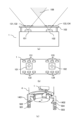
本実施形態では、図9(a)に示すように、照明基板103を介して同期ずれ検出照明111~114は単眼カメラ101、102の視野外に配置されている。 この場合、図9(b)に示すように、同期ずれ検出照明111、113を単眼カメラ101、102の上部に、同期ずれ検出照明112、114を単眼カメラ101、102の下部に配置している。同期ずれ検出照明111、113の駆動電源ラインは電気的に接続され、発光タイミングについては同時点灯/消灯が可能である。同様に、同期ずれ検出照明112、114の駆動電源ラインは電気的に接続され、発光タイミングについては同時点灯/消灯が可能である。
In this embodiment, as shown in FIG. 9(a), the synchronization error detection illuminators 111-114 are arranged outside the field of view of the
図9(b)のように、同期ずれ検出照明111、112の照射範囲115、116内に単眼カメラ101のレンズを含み、同期ずれ検出照明113、114の照射範囲117、118内に単眼カメラ102のレンズを含む。
As shown in FIG. 9(b), the lens of the
このような照明配置、および照射範囲の設定によると、同期ずれ検出照明111~114から強い光をレンズに向かって照射すると、単眼カメラ101、102内の鏡筒内部などで光の散乱、いわゆる迷光が発生する。同期ずれ検出照明111~114を点灯した状態で、単眼カメラ101、102を撮像した場合、レンズフレアが発生した画像を撮像できる。つまり、例えば、同期ずれ検出照明111を点灯して、単眼カメラ101で撮像した場合、同期ずれ検出照明111がある右上近傍だけが明るい画像を撮像することができる。
With this lighting arrangement and illumination range setting, when strong light is irradiated toward the lens from the synchronization deviation detection illuminations 111-114, light scattering, or so-called stray light, occurs inside the lens barrel of the
このように、本実施形態では、同期ずれ検出照明111~114が単眼カメラ101、102の撮影画角を外して配置されているが、その照射範囲は単眼カメラ101、102の撮影光学系の入射開口を一部、カバーしている。これにより、鏡筒内の迷光を利用して各照明の入射光を撮像することができる。
In this way, in this embodiment, the synchronization
本実施形態では、同期ずれ検出照明111~114の点灯によって、画像の一部領域の明るさが制御されることになる。これを利用して、実施形態1で示した、ステップS16(図4)の方法で、同期ずれ量を検出することができる。
In this embodiment, the brightness of a portion of the image is controlled by turning on the synchronization
本実施形態では、同期ずれ検出照明111~114は単眼カメラ101、102の視野外にあるため、両カメラは全視野が遮られることなく撮像することが可能となる。さらに、視野外近傍であれば同期ずれ検出照明111~114を設置すればよく、照明位置の微調整は不要となる。
In this embodiment, the synchronization error detection lighting 111-114 is outside the field of view of the
あるいは、本実施形態の変形例としては、次のような構成が考えられる。図10(a)、(b)に示すように、ステレオカメラ1の前面側に同期ずれ検出照明121~124を配置し、照明基板103のカメラ側に拡散板125を配置する。そして、照明基板103の裏面に拡散板125を設置し、同期ずれ検出照明121~124は拡散板125に対して光を照射する。この場合、拡散板125のサイズ、形状は、拡散光の照射範囲内に、単眼カメラ101、102のレンズを含むように取る。このような構成においても、同期ずれ検出照明121~124の発光により、上記同様に単眼カメラ101、102の鏡筒内で迷光を発生させ、レンズフレアが発生した画像を撮像できる。そして上記同様の手法を用いて同期合わせを行うことができる。
Alternatively, the following configuration can be considered as a modified example of this embodiment. As shown in Figs. 10(a) and (b), the synchronization
上記のように、カメラ側に同期ずれ検出照明121~124を配置し、拡散板125を用いる構成によれば、同期ずれ検出照明121~124から単眼カメラ101、102までの光路長を2倍にすることができる。従って、照明基板103を単眼カメラ101、102に近づけても、拡散板125からの拡散光の照射範囲を広くできる。これにより、照明基板103を単眼カメラ101、102に近接して配置できるようになり、ステレオカメラ1廻りの構成を小型化できる利点がある。
As described above, by arranging the synchronization deviation detection illuminations 121-124 on the camera side and using the
<実施形態4>
上述した実施形態1、2では、同期ずれ検出照明をステレオカメラ1のユニットに組み込んである。そのため、ステレオカメラ1のユニットが大型化・高価格化してしまう可能性がある。
<
In the above-described first and second embodiments, the synchronization deviation detection illumination is incorporated into the unit of the
本実施形態では、再帰反射材を利用してステレオカメラ1のユニット部分を比較的、小型軽量化できるような構成例を示す。また、本実施形態では、併せてステレオカメラ1をロボット装置の視覚系として用いる場合に有用な構成を示す。このロボット装置は、ワークから工業製品などの物品を製造するため、ステレオカメラ1とともに物品の生産ライン(生産システム)に配置される。ステレオカメラ1はロボット装置が操作する、例えばワークなどの3次元計測を行うために用いることができる。例えば、ステレオカメラ1によりワークやその組み付け部位を3次元計測し、それらの奥行きなどを含む3次元情報を取得し、取得した3次元情報に基づき、ロボット装置の動作を制御することができる。
In this embodiment, a configuration example is shown in which the unit part of the
以下では、実施形態1とは異なるハードウェアや制御系の構成の部分について図示、説明し、実施形態1と同様の部分については上記と同様の構成、作用が可能であるものとし、その詳細な説明については省略する。
Below, only the hardware and control system configurations that differ from those of
本実施形態では、図11(a)、(b)に示すように、同期ずれ検出照明131~134は照明基板103の前面に設置される。これら同期ずれ検出照明131~134の照射方向は、単眼カメラ101、102に向かう方向とは逆方向である。即ち、本実施形態では、同期ずれ検出照明の照明光は測定対象物に向かって照射する。また、図11(b)に示すように、同期ずれ検出照明131、132は、単眼カメラ101周辺に設置され、同期ずれ検出照明133、134は、単眼カメラ102周辺に設置される。また、図11(b)に示すように、同期ずれ検出照明131、133は単眼カメラ101、102の上部に、同期ずれ検出照明132、134は単眼カメラ101、102の下部に配置されている。同期ずれ検出照明131、133の駆動電源ラインは電気的に接続され、発光タイミングについては同時点灯/消灯が可能である。同様に、同期ずれ検出照明132、134の駆動電源ラインは電気的に接続され、発光タイミングについては同時点灯/消灯が可能である。
In this embodiment, as shown in Figs. 11(a) and (b), the synchronization
図11(c)に示すように、本実施形態のステレオカメラ1はロボット装置のロボットハンド4に装着されている。このような構成により、ステレオカメラ1で計測した測定対象物の3次元計測結果に基づき、例えば、ロボット装置のロボットハンド4の位置姿勢を制御することができる。
As shown in FIG. 11(c), the
ロボットハンド4は把持装置としてフィンガ1401、1402を備え、これらフィンガ1401、1402で測定対象物を把持することができる。そして、本実施形態では、フィンガ1401の先端部には、再帰反射マーク501を、中腹部には再帰反射マーク502を装着してある。同様に、フィンガ1402の先端部には再帰反射マーク503を、中腹部には再帰反射マーク504を装着してある。再帰反射マーク501~504はプラスチック材料などから構成することができ、これらの装着方法としてはネジ止めなどの他、接着など任意である。
The
再帰反射マーク501~504の装着位置ないしステレオカメラ1の配置位置で定まる、両者の相対位置関係は、ステレオカメラ1の共通視野108に再帰反射マーク501~504が含まれるよう決定する。
The relative positional relationship between the retroreflective marks 501-504, which is determined by the mounting positions of the retroreflective marks 501-504 or the position of the
同期ずれ検出照明131~134は、好ましくは指向性が高い照明光源により構成する。例えば、同期ずれ検出照明131を点灯させた場合、再帰反射マーク501近傍にのみ照明光が照射されるよう構成する。同様に同期ずれ検出照明132、133、134は、それぞれ再帰反射マーク502、503、504近傍にのみ照射されるよう構成する。
The out-of-
以上のように、同期ずれ検出照明131~134は単眼カメラ101、102の近傍に配置すれば、再帰反射マーク501~504からの反射光が単眼カメラ101、102に入射することになる。
As described above, if the synchronization deviation detection lighting 131-134 is placed near the
例えば、同期ずれ検出照明131、133を点灯して、単眼カメラ101、102で撮像した場合、再帰反射マーク501、503付近だけが明るい画像を撮像することができる。このように、画像の一部領域の明るさを制御できるため、実施形態1で示した、ステップS16(図4)の手法を用いて、同期ずれ量を検出することができる。
For example, when the synchronization
上記構成によれば、ある程度の光路長を確保した上で単眼カメラ101、102方向に照射する照明を設置する必要がなくなる。単眼カメラ101、102に入射可能な照明を設置するには、照明基板103と単眼カメラ101、102間の距離を長くなりがちである。しかしながら、本実施形態ではこのような照明方向を取る必要がなく、ステレオカメラ1廻りのユニットを小型化できる。
The above configuration eliminates the need to install lighting that illuminates in the direction of the
なお、照明基板103には、単眼カメラ101、102のそれぞれの撮影画角を確保するための開口を設けるか、あるいは照明基板103を透明材料などから構成すればよい。この点は本明細書における他の実施形態でも同様である。
The
また、本実施形態の同期ずれ検出照明131~134は、ステレオカメラ1で3次元計測のための照明として兼用してもよい。これにより、専用照明を設置することなく、単眼カメラ101、102の同期合わせが可能となり、ステレオカメラ1を簡単安価に構成できる。
The synchronization
本実施形態では、ステレオカメラ1をロボットハンド4に設置しているため、ステレオカメラ1とロボットハンド4の相対位置関係は変化しない。つまり、再帰反射マーク501~504は常時、ステレオカメラ1の共通視野内に入る。なお、再帰反射マークをワークなどの被写体側に配置する構成も考えられる。そのような構成では撮像箇所が複数ある場合、撮像箇所ごとに再帰反射材を設置する必要がある。これに対して、上記のようにロボットハンド4に再帰反射材を配置する構成では、再帰反射材を配置する準備工数が少なくなり、製造システムに係る設置作業は極めて容易に行える。
In this embodiment, the
なお、本実施形態では、再帰反射マーク501~504の4枚構成にしたが、再帰反射マークの数は任意であり、必要な撮像仕様に応じて増減して構わない。例えば、共通視野108の伸びる方向のほぼすべてを含む領域に、再帰反射マークを1枚貼付け、再帰反射マークからの反射光を実施形態2の同期ずれ検出照明の照明光と同様に取り扱い、実施形態2に示した手法で同期合わせを行うようにしてもよい。
In this embodiment, the system is configured with four
<実施形態5>
上述の実施形態1~4、特に実施形態1では、同期合わせを行う手法として、同期ずれ量が規定値以内となるまで、繰り返し1つの単眼カメラを電源OFF状態401(図3)として初期化する、というランダムな過程を利用する制御を示した。即ち、同期ずれ量が既定値以内になるまで、1つの単眼カメラを電源OFF状態401~初期化状態402~撮像パラメータ調整状態403~動画出力状態404と、繰返し状態遷移させる。同期合わせが完了するまでにかかる時間は確率に左右される。また、同期合わせがなかなか収束せず、実用上問題となる時間が経過してしまう可能性も否定できない。
<Embodiment 5>
In the above-mentioned first to fourth embodiments, particularly in the first embodiment, a control method using a random process was shown in which one monocular camera is repeatedly initialized in the power OFF state 401 (FIG. 3) until the amount of synchronization deviation falls within a specified value. That is, one monocular camera is repeatedly changed from the
即ち、上記のような制御では、特に同期ずれ量の既定値の許容範囲が狭い場合などでは、同期合わせが完了するまでに長時間かかる、また同期合わせが完了しない場合も考えられる。即ち、同期合わせにかかる時間を見積もることが難しい。また、別の問題として、カメラ間で露光周期のバラツキが大きい場合には、いったん同期合わせをした後に長時間が経過すると再度、同期ずれが生じ、時間とともにずれ量が拡大してしまうという可能性もある。 In other words, with the above control, it may take a long time to complete synchronization, or it may not be possible to complete synchronization at all, especially if the tolerance range for the default synchronization deviation is narrow. In other words, it is difficult to estimate the time required for synchronization. Another problem is that if there is a large variation in the exposure cycle between cameras, synchronization deviation may occur again if a long time has passed since synchronization was achieved, and the deviation may increase over time.
本実施形態では、3次元計測の期間中のタイミングで同期ずれを検出し、単眼カメラ101と単眼カメラ102が動画出力状態で連続的に出力する画像の内、最も同期ずれの少ない画像ペアを選択する構成を考え、これにより上記の問題に対処する。
In this embodiment, the above problem is addressed by detecting synchronization deviations during the 3D measurement period and selecting the image pair with the least synchronization deviation from among the images that are continuously output from
以下では、実施形態1とは異なるハードウェアや制御系の構成の部分について図示、説明し、実施形態1と同様の部分については上記と同様の構成、作用が可能であるものとし、その詳細な説明については省略する。
Below, only the hardware and control system configurations that differ from those of
本実施形態では、複数カメラの撮像システムの構成、ステレオカメラ1の各構成要素、画像処理装置2の各構成要素については、実施形態1~4と同様であるものとし、主に画像の選択を介して行う同期合わせの手法につき、説明する。
In this embodiment, the configuration of the multiple camera imaging system, the components of the
同期ずれ量の算出方法については、実施形態1~4と同様の手法により行う。ただし、本実施形態では、同期ずれ量に応じて動画出力状態となっている単眼カメラ102の画像は前後の少なくとも1フレーム分以上の複数フレームの画像を記憶部(メモリ、画像メモリ)から破棄せずにメモリ上に保管しておくものとする。
The method for calculating the amount of synchronization deviation is the same as in the first to fourth embodiments. However, in this embodiment, when the
(同期合わせ方法)
図12は、本実施形態における画像の選択を介して行う同期合わせの手順を示している。図12のステップS30では、同期ずれ量を算出する。これは上述の実施形態で示したいずれかの手法によって取得する。ただし、同期ずれ量を算出する際に、動画出力状態となっている単眼カメラ102の画像は前後のフレームの画像を破棄せずにメモリ上に保管しておく。
(Synchronization method)
Fig. 12 shows the procedure for synchronizing through image selection in this embodiment. In step S30 in Fig. 12, the amount of synchronization deviation is calculated. This is obtained by any of the methods shown in the above-mentioned embodiments. However, when calculating the amount of synchronization deviation, images from the
ステップS31では、単眼カメラ102の単眼カメラ101に対する同期ずれ(進み)量が+1/2フレーム以上か否かを判定する。例えば単眼カメラ101、102のフレームレートが25FPS(1フレームあたり0.04秒)であれば、単眼カメラ102の単眼カメラ101に対する同期ずれ(進み)量が+0.02秒以上か否かを判定する。+1/2フレーム以上であるならば(ステップS31のYES)、その後ステップS35へ進む。また、+1/2フレーム未満であるならば(ステップS31のNO)、その後ステップS32へ進む。
In step S31, it is determined whether the amount of synchronization deviation (lead) of
ステップS32では、単眼カメラ102の単眼カメラ101に対する同期ずれ(進み)量が-1/2フレーム以下か否かを判定する。例えば単眼カメラ101、102のフレームレートが25FPSであれば、単眼カメラ102の単眼カメラ101に対する同期ずれ(進み)量が-0.02秒以下か否かを判定する。-1/2フレーム以下であるならば(ステップS32のYES)、その後ステップS34へ進む。また、-1/2フレームより大きいならば(ステップS32のNO)、その後ステップS33へ進む。
In step S32, it is determined whether the amount of synchronization deviation (lead) of
ステップS33では、単眼カメラ101の画像と単眼カメラ102の画像を同期合わせされた画像ペアとして選定する。ステップS34では、単眼カメラ101の画像とメモリ上に保管された単眼カメラ102の次のフレームの画像を、同期合わせされた画像ペアとして選定する。
In step S33, the image from
ステップS35では、単眼カメラ101の画像とメモリ上に保管された単眼カメラ102の前のフレームの画像を、同期合わせされた画像ペアとして選定する。
In step S35, the image from
以上では、単眼カメラ101と102の同期ずれ量が1フレーム以内である場合に適用可能な同期合わせ手法である。しかしながら、もし、単眼カメラ101と102の同期ずれ量が1フレームを超える場合には、例えば、同期ずれ量(フレーム単位)のうち整数部分の数値を用いてフレームをシフトさせる。その上で、シフトされたフレームの画像を基準として、小数点以下部分の数値を用いて上記と同様に使用する画像を選択することができる。
The above is a synchronization method that can be applied when the amount of synchronization deviation between the
例えば、ここで単眼カメラ102が単眼カメラ101に対して2.4フレーム進んでいるとする。この場合には、単眼カメラ102の取得画像より2フレーム前の画像を基準とし、同期ずれ量0.4フレームを、ステップS31で判定し、1/2フレーム以上進んでいないのでステップS32の判定へ進む。ステップS32の判定では、1/2フレーム以上遅れていないのでステップS33へ進み、2フレーム前の画像を基準として画像ペアを選択する。この場合には、結果的に単眼カメラ101の画像と、単眼カメラ102の画像の2フレーム前の画像が画像ペアとなる。
For example, suppose
上記のようにして3次元計測に用いる画像として何フレーム離れた画像をペアとするかは、例えば3次元計測前や、3次元計測処理を行っていない時間に予め決定しておくこともできる。即ち、単眼カメラ101の画像に対する単眼カメラ102の画像として、単眼カメラ101と同時に取得した画像を使用するか、単眼カメラ101と同時に取得した画像の前のフレーム、あるいは次のフレームの画像を使うか、を予め決定しておく。もしくは、同期合わせ処理を3次元計測ごとに実行し、単眼カメラ101の画像に対する単眼カメラ102の画像として使用するフレームを決定してもよい。
As described above, the number of frames apart to pair images for use in 3D measurement can be determined in advance, for example, before 3D measurement or at a time when 3D measurement processing is not being performed. That is, it is determined in advance whether to use an image acquired simultaneously with the
なお、本実施形態では単眼カメラ101の画像に対応する単眼カメラ102の画像として使用するフレームを決定したが、逆に、単眼カメラ102の画像に対応する単眼カメラ101の画像として使用するフレームを決定してもよい。また、基準とするカメラを3次元計測に係る諸条件に応じて切り換えるような制御を行ってもよい。
In this embodiment, a frame is determined to be used as an image of
また、本実施形態による同期合わせは、複数カメラの同期合わせ全般に適用可能である。しかしながら、本実施形態3次元計測中に同期ずれ検出照明を点灯させる場合には、好ましくはステレオカメラ1の各単眼カメラはグローバルシャッタカメラで構成する。もし、本実施形態による同期合わせをローリングシャッタカメラで構成されたステレオカメラに適用する場合には、計測に使用する画像上で、照明光が撮像されるタイミングのラインが帯状に明るくなりノイズとなる。そのため、3次元計測の妨げになる可能性がある。このようにグローバルシャッタカメラを用いることにより、同期合わせ照明の3次元計測に対する影響を低減することができる。
The synchronization according to this embodiment can be applied to the synchronization of multiple cameras in general. However, if the synchronization deviation detection illumination is turned on during the three-dimensional measurement of this embodiment, each monocular camera of the
あるいは、ローリングシャッタカメラから成るステレオカメラを用い、3次元計測中に同期ずれ検出照明を点灯させる場合には、次のような構成を取ってもよい。例えば、実施形態1のように単眼カメラ101および102の共通視野ではない、3次元計測では使用しない領域に同期ずれ検出照明を配置する構成とすることが考えられる。このような構成により、同期ずれ検出照明により3次元計測を妨げることなく、撮像タイミングの同期合わせを行うことができる。
Alternatively, when using a stereo camera consisting of rolling shutter cameras and turning on the synchronization deviation detection illumination during 3D measurement, the following configuration may be used. For example, as in
本実施形態のように同期ずれ量の大きさに基づき、3次元計測に用いるフレーム画像を選択する構成によれば、同期合わせが完了するまでにかかる時間は確率に左右されない。同期合わせが完了するまでにかかる所要時間を短時間かつ一定に保つことができる。また、同期合わせ処理は、3次元計測の度に実行することもでき、長時間計測を継続しても同期ずれが生じないという効果を期待できる。 According to the configuration of this embodiment in which frame images to be used for 3D measurement are selected based on the magnitude of the synchronization deviation, the time required to complete synchronization is not dependent on probability. The time required to complete synchronization can be kept short and constant. In addition, the synchronization process can be performed every time 3D measurement is performed, and it is expected that synchronization deviation will not occur even if measurement is continued for a long period of time.
<実施形態6>
上述した実施形態1~5では、ステレオカメラ1を単眼カメラ101、102の2台のカメラを用いて構成したが、3台以上のカメラを用いることも考えられる。3次元計測に用いる2台のカメラ以外に単眼カメラを設けておけば、例えば3次元計測中の2台のカメラの同期ずれ量を監視し、3次元計測に用いる単眼カメラのペア(組合せ)を切り換えることができる。3次元計測に用いる単眼カメラの組合せを切り換えるタイミングとしては、3次元計測中の2台のカメラの同期ずれ量が大きくなった時が考えられる。また、定期的なタイミングで、3次元計測に用いる単眼カメラのペア(組合せ)を切り換えるような制御も考えられる。その場合、例えば、後述のように単眼カメラ101、102のペアを2組用意しておき、片方のペアで3次元計測中に他方のペアで予め同期ずれ検出と、それに基づく同期合わせを行っておく制御などを行うことができる。
<Embodiment 6>
In the above-described first to fifth embodiments, the
上述した実施形態1~5では、単眼カメラ101、102の間で露光周期のバラツキが大きいような場合、いったん同期合わせをした後に長時間が経過すると再度同期ずれが生じ、時間とともにずれ量が拡大してしまう可能性がある。また、同期ずれ検出照明の配置などによっては、同期がずれた場合、同期を合わせるためには一度、3次元計測を中断する必要が生じる。本実施形態によれば、3台以上の複数の単眼カメラを用いて上記のような問題に対処できる。
In the above-mentioned first to fifth embodiments, if there is a large variation in the exposure period between the
以下では、実施形態1とは異なるハードウェアや制御系の構成の部分について図示、説明し、実施形態1と同様の部分については上記と同様の構成、作用が可能であるものとし、その詳細な説明については省略する。
Below, only the hardware and control system configurations that differ from those of
図13に一例を示すが、本実施形態では、ステレオカメラ1には、3つのカメラ、単眼カメラ101、単眼カメラ102、単眼カメラ110を配置する。図13は図1(b)と同等の様式でステレオカメラ1の構成を示している。単眼カメラ101、単眼カメラ102は、実施形態1と同等に所定の基線長だけ、離間して配置される。この時、単眼カメラ101と単眼カメラ110の撮像光学系が離間する基線長が単眼カメラ101、102の基線長と同じになるよう配置してある。
As shown in FIG. 13 as an example, in this embodiment, three cameras,
そして、同図に示すように、単眼カメラ101、102、110に対して同期ずれ検出照明104~107および109を配置する。同期ずれ検出照明107は、両カメラの中間に配置し、単眼カメラ102、または110のために共用できるような構成としてある。
As shown in the figure, synchronization
このような構成により、例えば3次元計測中の単眼カメラ101、102の同期ずれ量を監視し、例えば同期ずれが生じた際に、3次元計測に用いるカメラの系統を切り換えることができる。例えば、3次元計測に用いるカメラの系統を単眼カメラ101、102の第1の組合せから単眼カメラ101、110の第2の組合せに切り換える。このような構成により、3次元計測と並行して3次元計測を遅滞させることなく同期合わせを行うことができる。
With this configuration, for example, the amount of synchronization deviation between the
逆に、単眼カメラ101、110で3次元計測をしている間に、単眼カメラ101、110の同期ずれ量を監視することができる。そして、同期ずれが生じた際に単眼カメラ101、102に3次元計測に用いるカメラを切り換える。これにより、単眼カメラ101と単眼カメラ102で計測を継続することができる。このようにして、2つのステレオ撮像系の3次元計測と、同期合わせの役割を必要に応じて交互に切り換えることにより、3次元計測を中断、遅滞させることなく、常に同期の取れたステレオ撮像系により3次元計測を続行することができる。
Conversely, while 3D measurement is being performed with
(計測カメラ切り換え方法)
ここで、2つのステレオ撮像系を構成する単眼カメラ101、102、110の切り換え制御の具体例を図14に示す。図14は、これらカメラの切り換え制御手順の一例を示している。
(Measuring camera switching method)
A specific example of switching control of the
図14のステップS40では、単眼カメラ101と単眼カメラ102で3次元計測を開始する。ステップS41では、単眼カメラ101と単眼カメラ102の同期ずれ量を算出する。この同期ずれ量の算出の手法としては、同期ずれ検出照明104~107を用いた実施形態1と同等の手法を用いることができる。
In step S40 of FIG. 14, three-dimensional measurement is started by the
ステップS42では、単眼カメラ101、102の同期ずれ量が所定の閾値以上かを判定する。単眼カメラ101、102の同期ずれ量が閾値以内であるならば(ステップ42のNO)、ステップS41に復帰して再度、同期ずれ量を確認する。また、単眼カメラ101、102の同期ずれ量が閾値以上であるならば(ステップS42のYES)、ステップS43に進む。
In step S42, it is determined whether the amount of synchronization deviation between the
ステップS43では、単眼カメラ101と単眼カメラ110の同期合わせを開始する。この同期合わせ処理は、例えば実施形態1におけるように、同期ずれ量が規定値以内となるまで単眼カメラ110の電源OFF~初期化…の状態遷移を繰り返し行う手法によって行うことができる。また、単眼カメラ101、110の同期合わせ上述の他の手法によって行ってもよい。
In step S43, synchronization between the
ステップS44では、3次元計測に用いる撮像系を単眼カメラ101と単眼カメラ110の側に切り換えて、3次元計測を開始する。即ち、3次元計測に用いるカメラを単眼カメラ101および単眼カメラ102から、単眼カメラ101および単眼カメラ110に切り換える。その後、同期ずれ量を監視するカメラと、同期合わせをするカメラを変えながら、所期の3次元計測が終了するまでステップS41からステップS44までを繰り返す。
In step S44, the imaging system used for 3D measurement is switched to
以上では、ステレオカメラ1を構成する複数の単眼カメラが3つである例を示したが、より多数の単眼カメラによりステレオカメラ1を構成してもよい。例えば、単眼カメラを4つ以上用い、同期ずれ量を算出する撮像系と、同期合わせする撮像系を切り換えてもよい。このように同期ずれ量を算出する撮像系と、同期合わせする撮像系を並列的に動作させることができる構成には大きなメリットがある。例えば、ある単眼カメラの撮像系で3次元計測中に、並行して別の単眼カメラの撮像系で同期合せを実行することができる。この構成では、例えば3次元計測のための撮像系を切り換える必要が生じた場合には、図14に示したような同期合せ処理の処理時間を必要とせず、高速に、既に同期合せ済みの撮像系への切り換えを行うことができる。
Although the above shows an example in which the
なお、図13に示した単眼カメラ102および単眼カメラ110と、単眼カメラ101の左右の位置関係は、図13の図示とは異なる位置関係であっても構わない。例えば、単眼カメラ101を中心として、単眼カメラ102と単眼カメラ110を一直線上になるような配置も考えられるし、3つの単眼カメラが正三角形をなすような等間隔配置であってもよい。また、以上では、単眼カメラ101と単眼カメラ102、あるいは単眼カメラ101と単眼カメラ110のそれぞれの組を3次元計測に用いるものとして説明した。しかしながら、単眼カメラの配置によっては単眼カメラ102と単眼カメラ110の組を計測に用いても構わない。
The left-right positional relationship between
以上に示した実施形態の構成はあくまでも一例であって、本発明を逸脱しない範囲で、当業者には種々の設計変更が可能である。例えば、以上では、同期撮像を行う複数の単眼カメラは、3次元計測のためのステレオカメラを構成するものとして説明した。しかしながら、本発明のハードウェア構成や撮像制御が、何らかの目的で同期撮像を行う必要のある、複数の単眼カメラで構成された撮像システムにおいて実施できるのはいうまでもない。 The configuration of the embodiment shown above is merely an example, and various design changes are possible for those skilled in the art without departing from the scope of the present invention. For example, in the above, multiple monocular cameras performing synchronous imaging have been described as constituting a stereo camera for three-dimensional measurement. However, it goes without saying that the hardware configuration and imaging control of the present invention can be implemented in an imaging system composed of multiple monocular cameras that need to perform synchronous imaging for some purpose.
また、以上に示した実施形態のステレオカメラ1はロボット装置のロボットハンド4に設けられる構成を説明したが、これに限られない。制御装置に設けられる記憶装置の情報に基づき、伸縮、屈伸、上下移動、左右移動もしくは旋回の動作またはこれらの複合動作を自動的に行うことができる機械に適用可能である。
In addition, the
1…ステレオカメラ、2…画像処理装置、101、102、110…単眼カメラ、103…照明基板、108…共通視野、104~107、109、111~114、121~124、131~134…同期ずれ検出照明、115~118…照射範囲、125…拡散板、130…外部照明、201…カメラ制御部、202…照明制御部、203…同期ずれ量演算部、204…同期合わせ制御部、205…3次元計測部、301…集光部、302…イメージセンサ、4…ロボットハンド、1401、1402…フィンガ、501~504…再帰反射マーク。 1... stereo camera, 2... image processing device, 101, 102, 110... monocular camera, 103... lighting board, 108... common field of view, 104-107, 109, 111-114, 121-124, 131-134... synchronization deviation detection lighting, 115-118... irradiation range, 125... diffusion plate, 130... external lighting, 201... camera control unit, 202... lighting control unit, 203... synchronization deviation amount calculation unit, 204... synchronization adjustment control unit, 205... three-dimensional measurement unit, 301... light collection unit, 302... image sensor, 4... robot hand, 1401, 1402... fingers, 501-504... retroreflective marks.
Claims (17)
照明装置と、
当該照明装置で照明された領域の画像を撮像する第1のカメラおよび第2のカメラと、
制御装置と、を備え、
前記制御装置は、
前記第1および第2のカメラそれぞれで、所定の時間間隔の撮像タイミングで画像を撮像させる際に、前記照明装置を所定の時間間隔の点灯/消灯パターンで照明光を照射するように制御することで、前記第1および第2のカメラに前記撮像タイミングに応じた輝度パターンを含む画像を撮像させ、
前記第1のカメラで撮像された画像の前記輝度パターンと、前記第2のカメラで撮像された画像の前記輝度パターンとを用いて、前記第1のカメラと前記第2のカメラの前記撮像タイミングの同期ずれを検出し、
検出した前記同期ずれに基づいて、前記第1のカメラまたは前記第2のカメラの初期化または電源OFFを伴う処理で前記第1のカメラまたは前記第2のカメラの前記撮像タイミングを変更して同期合わせを行い、
前記照明装置の前記所定の時間間隔は、前記第1および第2のカメラのフレームレートよりも短いことを特徴とする撮像システム。 In the imaging system,
A lighting device;
a first camera and a second camera for capturing an image of an area illuminated by the illumination device;
A control device,
The control device includes:
When the first and second cameras are caused to capture images at imaging timings of a predetermined time interval, the lighting device is controlled to irradiate illumination light in a light-on/light-off pattern at a predetermined time interval, thereby causing the first and second cameras to capture images including a luminance pattern according to the imaging timings;
detecting a synchronization error between the image capturing timings of the first camera and the second camera by using the luminance pattern of the image captured by the first camera and the luminance pattern of the image captured by the second camera;
based on the detected synchronization deviation, performing a process involving initialization or power OFF of the first camera or the second camera to change the image capturing timing of the first camera or the second camera to perform synchronization;
11. An imaging system, comprising: an imaging device, the predetermined time interval for the illumination device being shorter than a frame rate of the first and second cameras.
前記制御装置は、
前記第1のカメラが第1の時刻に撮像した第1の画像と、前記第2のカメラが第2の時刻に撮像した第2の画像と、から、前記第1の時刻と前記第2の時刻との差に基づく量を算出し、
前記量が規定値以内かどうかを判定することにより、前記同期ずれが発生しているか否かを検出する撮像システム。 3. The imaging system according to claim 1,
The control device includes:
calculating an amount based on a difference between a first image captured by the first camera at a first time and a second image captured by the second camera at a second time;
The imaging system detects whether or not the synchronization error has occurred by determining whether or not the amount is within a specified value.
前記第1のカメラまたは前記第2のカメラが、被写体の3次元情報を取得するステレオカメラを構成する撮像システム。 4. The imaging system according to claim 1,
An imaging system in which the first camera or the second camera constitutes a stereo camera that acquires three-dimensional information of a subject.
前記照明装置を構成する発光体が、前記第1および第2のカメラを互いに位置決めする筐体に装着されている撮像システム。 5. The imaging system according to claim 1,
An imaging system in which a light emitter constituting the illumination device is mounted in a housing that positions the first and second cameras relative to each other.
前記照明装置を構成する発光体の照射方向が前記第1および第2のカメラの撮像光学系に向かう照射方向を含む撮像システム。 6. The imaging system according to claim 1,
An imaging system in which the irradiation direction of a light-emitting body constituting the illumination device includes an irradiation direction toward the imaging optical systems of the first and second cameras.
前記照明装置は、前記第1のカメラの撮像領域に配置された第1の発光体と前記第2のカメラの撮像領域に配置された第2の発光体とを含み、
前記第1の発光体と前記第2の発光体とは、駆動電源ラインが共通に接続され、同じ発光タイミングで照明光を照射する撮像システム。 7. The imaging system according to claim 1,
the illumination device includes a first light emitter arranged in an imaging area of the first camera and a second light emitter arranged in an imaging area of the second camera;
The first light emitter and the second light emitter are connected to a common drive power supply line and emit illumination light at the same light emission timing.
前記照明装置は、前記第1および第2のカメラの共通視野の内に設置されている撮像システム。 8. The imaging system according to claim 1,
The imaging system, wherein the illumination device is located within a common field of view of the first and second cameras.
前記制御装置は、前記画像における前記輝度パターンの位置に基づいて同期ずれを検出する撮像システム。 9. The imaging system according to claim 1,
The control device detects synchronization deviation based on a position of the luminance pattern in the image.
前記制御装置は、前記画像における前記輝度パターンの比率に基づいて前記同期ずれを検出する撮像システム。 9. The imaging system according to claim 1,
The control device detects the synchronization error based on a ratio of the luminance patterns in the image.
前記画像における前記輝度パターンは、照明光が点灯状態で撮像された部分と、照明光が消灯状態で撮像された部分とによって形成される撮像システム。 11. The imaging system according to claim 1,
An imaging system, wherein the luminance pattern in the image is formed by a portion captured with an illumination light turned on and a portion captured with the illumination light turned off.
ワークを操作するロボット装置と、
前記撮像システムの前記第1および第2のカメラにより取得した前記ワークの3次元情報に基づき、前記ロボット装置を制御するロボット制御装置と、を備えた製造システム。 An imaging system according to any one of claims 1 to 11,
A robot device for manipulating a workpiece;
a robot control device that controls the robot device based on three-dimensional information of the workpiece acquired by the first and second cameras of the imaging system.
前記照明装置から照射された照明光を反射する再帰反射材が、前記ロボット装置の把持装置に装着され、前記再帰反射材により反射された前記照明光を前記第1および第2のカメラにより撮像し、前記制御装置が前記反射された照明光の像に対する画像処理を介して、前記第1および第2のカメラの撮像タイミングの同期ずれを検出する製造システム。 13. The manufacturing system of claim 12,
A manufacturing system in which a retroreflective material that reflects illumination light emitted from the lighting device is attached to a gripping device of the robot device, the illumination light reflected by the retroreflective material is captured by the first and second cameras, and the control device detects a synchronization discrepancy in the imaging timing of the first and second cameras through image processing of the image of the reflected illumination light.
前記照明装置を所定の時間間隔の点灯/消灯パターンで照明光を照射するように制御する工程と、
前記照明光が照明されている状態で、前記第1および第2のカメラのそれぞれにおいて所定の時間間隔の撮像タイミングで撮像され、前記撮像タイミングに応じた輝度パターンを含む画像を取得する工程と、
前記第1のカメラで撮像された画像の前記輝度パターンと、前記第2のカメラで撮像された画像の前記輝度パターンとを用いて、前記第1のカメラと前記第2のカメラの前記撮像タイミングの同期ずれを検出する工程と、
検出した前記同期ずれに基づいて、前記第1のカメラまたは前記第2のカメラの初期化または電源OFFを伴う処理で前記第1のカメラまたは前記第2のカメラの前記撮像タイミングを変更して同期合わせを行う工程と、を有し、
前記照明装置の前記所定の時間間隔は、前記第1および前記第2のカメラのフレームレートよりも短いことを特徴とする制御方法。 1. A method for controlling a control device in an imaging system having a lighting device, a first camera and a second camera that capture an image of an area illuminated by the lighting device, and a control device , the method comprising the steps of:
controlling the lighting device to emit illumination light in a turn-on/turn-off pattern at a predetermined time interval;
acquiring images captured by the first and second cameras at image capturing timings at a predetermined time interval while the illumination light is applied, the images including a luminance pattern corresponding to the image capturing timings;
detecting a synchronization error between the image capturing timings of the first camera and the second camera by using the luminance pattern of an image captured by the first camera and the luminance pattern of an image captured by the second camera;
and changing the image capturing timing of the first camera or the second camera to perform synchronization based on the detected synchronization deviation through a process involving initialization or power OFF of the first camera or the second camera,
4. A method for controlling a lighting device, comprising: a step of: detecting a frame rate of the first and second cameras;
Priority Applications (3)
| Application Number | Priority Date | Filing Date | Title |
|---|---|---|---|
| JP2020107619A JP7588972B2 (en) | 2020-06-23 | 2020-06-23 | Imaging system, manufacturing system, control method, article manufacturing method, control program, and recording medium |
| US17/349,527 US20210400252A1 (en) | 2020-06-23 | 2021-06-16 | Imaging method, imaging system, manufacturing system, and method for manufacturing a product |
| CN202110678706.3A CN113840133B (en) | 2020-06-23 | 2021-06-18 | Imaging method, imaging system, manufacturing system, and method for manufacturing product |
Applications Claiming Priority (1)
| Application Number | Priority Date | Filing Date | Title |
|---|---|---|---|
| JP2020107619A JP7588972B2 (en) | 2020-06-23 | 2020-06-23 | Imaging system, manufacturing system, control method, article manufacturing method, control program, and recording medium |
Publications (3)
| Publication Number | Publication Date |
|---|---|
| JP2022003730A JP2022003730A (en) | 2022-01-11 |
| JP2022003730A5 JP2022003730A5 (en) | 2023-06-06 |
| JP7588972B2 true JP7588972B2 (en) | 2024-11-25 |
Family
ID=78962706
Family Applications (1)
| Application Number | Title | Priority Date | Filing Date |
|---|---|---|---|
| JP2020107619A Active JP7588972B2 (en) | 2020-06-23 | 2020-06-23 | Imaging system, manufacturing system, control method, article manufacturing method, control program, and recording medium |
Country Status (3)
| Country | Link |
|---|---|
| US (1) | US20210400252A1 (en) |
| JP (1) | JP7588972B2 (en) |
| CN (1) | CN113840133B (en) |
Families Citing this family (3)
| Publication number | Priority date | Publication date | Assignee | Title |
|---|---|---|---|---|
| JP7619014B2 (en) * | 2020-11-17 | 2025-01-22 | セイコーエプソン株式会社 | Molding machine management system and computer program |
| CN118696545A (en) * | 2022-02-18 | 2024-09-24 | 索尼集团公司 | Information processing device, information processing method and information processing program |
| WO2025041988A1 (en) * | 2023-08-21 | 2025-02-27 | 삼성전자 주식회사 | Electronic device comprising plurality of cameras, and operating method thereof |
Citations (5)
| Publication number | Priority date | Publication date | Assignee | Title |
|---|---|---|---|---|
| JP2004117049A (en) | 2002-09-24 | 2004-04-15 | Fuji Heavy Ind Ltd | Stereo image processing apparatus and stereo image processing method |
| JP2012138671A (en) | 2010-12-24 | 2012-07-19 | Kyocera Corp | Stereo camera device |
| JP2014175931A (en) | 2013-03-11 | 2014-09-22 | Canon Inc | Photographing system, imaging apparatus, and control method therefor |
| JP2018061138A (en) | 2016-10-05 | 2018-04-12 | 株式会社東芝 | Imaging system, processor, common visual field detection method, and common visual field detection program |
| WO2018101034A1 (en) | 2016-11-29 | 2018-06-07 | ソニー株式会社 | Imaging device, imaging control method, and program |
Family Cites Families (7)
| Publication number | Priority date | Publication date | Assignee | Title |
|---|---|---|---|---|
| JP4899149B2 (en) * | 2006-02-13 | 2012-03-21 | 株式会社ジェイエイアイコーポレーション | Frame sequential color camera system |
| US20070229850A1 (en) * | 2006-04-04 | 2007-10-04 | Boxternal Logics, Llc | System and method for three-dimensional image capture |
| US9608725B2 (en) * | 2012-12-27 | 2017-03-28 | Panasonic Intellectual Property Corporation Of America | Information processing program, reception program, and information processing apparatus |
| US8988509B1 (en) * | 2014-03-20 | 2015-03-24 | Gopro, Inc. | Auto-alignment of image sensors in a multi-camera system |
| US20160189387A1 (en) * | 2014-12-24 | 2016-06-30 | Lensbricks Technology Private Limited | Methods and Apparatus for Depth Sensing |
| JP6790752B2 (en) * | 2015-11-20 | 2020-11-25 | 株式会社リコー | Image reader, image forming device and image reading method |
| US10705598B2 (en) * | 2017-05-09 | 2020-07-07 | Microsoft Technology Licensing, Llc | Tracking wearable device and handheld object poses |
-
2020
- 2020-06-23 JP JP2020107619A patent/JP7588972B2/en active Active
-
2021
- 2021-06-16 US US17/349,527 patent/US20210400252A1/en not_active Abandoned
- 2021-06-18 CN CN202110678706.3A patent/CN113840133B/en active Active
Patent Citations (5)
| Publication number | Priority date | Publication date | Assignee | Title |
|---|---|---|---|---|
| JP2004117049A (en) | 2002-09-24 | 2004-04-15 | Fuji Heavy Ind Ltd | Stereo image processing apparatus and stereo image processing method |
| JP2012138671A (en) | 2010-12-24 | 2012-07-19 | Kyocera Corp | Stereo camera device |
| JP2014175931A (en) | 2013-03-11 | 2014-09-22 | Canon Inc | Photographing system, imaging apparatus, and control method therefor |
| JP2018061138A (en) | 2016-10-05 | 2018-04-12 | 株式会社東芝 | Imaging system, processor, common visual field detection method, and common visual field detection program |
| WO2018101034A1 (en) | 2016-11-29 | 2018-06-07 | ソニー株式会社 | Imaging device, imaging control method, and program |
Also Published As
| Publication number | Publication date |
|---|---|
| US20210400252A1 (en) | 2021-12-23 |
| JP2022003730A (en) | 2022-01-11 |
| CN113840133A (en) | 2021-12-24 |
| CN113840133B (en) | 2025-03-11 |
Similar Documents
| Publication | Publication Date | Title |
|---|---|---|
| JP7588972B2 (en) | Imaging system, manufacturing system, control method, article manufacturing method, control program, and recording medium | |
| US8866114B2 (en) | Vision measuring device | |
| TWI631849B (en) | Apparatus for generating depth image | |
| KR100497636B1 (en) | Electronic component mounting apparatus | |
| CN113170042B (en) | Information processing apparatus, information processing system, and device information acquisition method | |
| JP2018119942A (en) | Imaging apparatus, monitoring method thereof, and program | |
| US9435646B2 (en) | Displacement detection device and operating method thereof | |
| US20190182418A1 (en) | Grouped Photography Studio Lighting System with Software Driven and Simultaneous Wireless Dimming Control and Related Photography System | |
| JP5973704B2 (en) | Projection control apparatus and projection control method | |
| KR101288030B1 (en) | Hybrid 3D scanner | |
| US20140043439A1 (en) | Method for operating a camera and a projector in a synchronized manner | |
| JP2013124941A (en) | Distance measuring apparatus and distance measuring method | |
| TWI293110B (en) | Apparatus for and method of measuring image | |
| US20220028117A1 (en) | System, information processing method, method of manufacturing product, and recording medium | |
| WO2016031350A1 (en) | Control device, control method, and program | |
| US7581313B2 (en) | Component mounting method and mounter | |
| US20160212396A1 (en) | Display apparatus capable of seamlessly displaying a plurality of projection images on screen | |
| JP2006292385A (en) | Visual information processing system and visual information processing method thereof | |
| US10533845B2 (en) | Measuring device, measuring method, system and manufacturing method | |
| US20150092104A1 (en) | Strobe device and photography device provided with same | |
| JP2022003729A (en) | Imaging method, imaging system, manufacturing system, and manufacturing method of goods | |
| JP2022003728A (en) | Imaging method, imaging system, manufacturing system, and method for manufacturing article | |
| US20160191878A1 (en) | Image projection device | |
| JP2009159572A (en) | Light receiving unit and optical communication device | |
| CN109981993A (en) | Depth camera projector power consumption control method and its application |
Legal Events
| Date | Code | Title | Description |
|---|---|---|---|
| A521 | Request for written amendment filed |
Free format text: JAPANESE INTERMEDIATE CODE: A523 Effective date: 20230526 |
|
| A621 | Written request for application examination |
Free format text: JAPANESE INTERMEDIATE CODE: A621 Effective date: 20230526 |
|
| A977 | Report on retrieval |
Free format text: JAPANESE INTERMEDIATE CODE: A971007 Effective date: 20240513 |
|
| A131 | Notification of reasons for refusal |
Free format text: JAPANESE INTERMEDIATE CODE: A131 Effective date: 20240702 |
|
| A521 | Request for written amendment filed |
Free format text: JAPANESE INTERMEDIATE CODE: A523 Effective date: 20240822 |
|
| A131 | Notification of reasons for refusal |
Free format text: JAPANESE INTERMEDIATE CODE: A131 Effective date: 20240910 |
|
| A521 | Request for written amendment filed |
Free format text: JAPANESE INTERMEDIATE CODE: A523 Effective date: 20240930 |
|
| TRDD | Decision of grant or rejection written | ||
| A01 | Written decision to grant a patent or to grant a registration (utility model) |
Free format text: JAPANESE INTERMEDIATE CODE: A01 Effective date: 20241015 |
|
| A61 | First payment of annual fees (during grant procedure) |
Free format text: JAPANESE INTERMEDIATE CODE: A61 Effective date: 20241113 |
|
| R150 | Certificate of patent or registration of utility model |
Ref document number: 7588972 Country of ref document: JP Free format text: JAPANESE INTERMEDIATE CODE: R150 |