JP7588970B2 - Visual Distinction of Primary and Secondary Activation in Electrophysiological Maps - Google Patents
Visual Distinction of Primary and Secondary Activation in Electrophysiological Maps Download PDFInfo
- Publication number
- JP7588970B2 JP7588970B2 JP2020100736A JP2020100736A JP7588970B2 JP 7588970 B2 JP7588970 B2 JP 7588970B2 JP 2020100736 A JP2020100736 A JP 2020100736A JP 2020100736 A JP2020100736 A JP 2020100736A JP 7588970 B2 JP7588970 B2 JP 7588970B2
- Authority
- JP
- Japan
- Prior art keywords
- activation
- processor
- primary
- bipolar intracardiac
- intracardiac egm
- Prior art date
- Legal status (The legal status is an assumption and is not a legal conclusion. Google has not performed a legal analysis and makes no representation as to the accuracy of the status listed.)
- Active
Links
Images

Classifications
-
- A—HUMAN NECESSITIES
- A61—MEDICAL OR VETERINARY SCIENCE; HYGIENE
- A61B—DIAGNOSIS; SURGERY; IDENTIFICATION
- A61B5/00—Measuring for diagnostic purposes; Identification of persons
- A61B5/24—Detecting, measuring or recording bioelectric or biomagnetic signals of the body or parts thereof
- A61B5/316—Modalities, i.e. specific diagnostic methods
- A61B5/318—Heart-related electrical modalities, e.g. electrocardiography [ECG]
- A61B5/339—Displays specially adapted therefor
-
- A—HUMAN NECESSITIES
- A61—MEDICAL OR VETERINARY SCIENCE; HYGIENE
- A61B—DIAGNOSIS; SURGERY; IDENTIFICATION
- A61B5/00—Measuring for diagnostic purposes; Identification of persons
- A61B5/0033—Features or image-related aspects of imaging apparatus, e.g. for MRI, optical tomography or impedance tomography apparatus; Arrangements of imaging apparatus in a room
- A61B5/0035—Features or image-related aspects of imaging apparatus, e.g. for MRI, optical tomography or impedance tomography apparatus; Arrangements of imaging apparatus in a room adapted for acquisition of images from more than one imaging mode, e.g. combining MRI and optical tomography
-
- A—HUMAN NECESSITIES
- A61—MEDICAL OR VETERINARY SCIENCE; HYGIENE
- A61B—DIAGNOSIS; SURGERY; IDENTIFICATION
- A61B5/00—Measuring for diagnostic purposes; Identification of persons
- A61B5/0033—Features or image-related aspects of imaging apparatus, e.g. for MRI, optical tomography or impedance tomography apparatus; Arrangements of imaging apparatus in a room
- A61B5/004—Features or image-related aspects of imaging apparatus, e.g. for MRI, optical tomography or impedance tomography apparatus; Arrangements of imaging apparatus in a room adapted for image acquisition of a particular organ or body part
- A61B5/0044—Features or image-related aspects of imaging apparatus, e.g. for MRI, optical tomography or impedance tomography apparatus; Arrangements of imaging apparatus in a room adapted for image acquisition of a particular organ or body part for the heart
-
- A—HUMAN NECESSITIES
- A61—MEDICAL OR VETERINARY SCIENCE; HYGIENE
- A61B—DIAGNOSIS; SURGERY; IDENTIFICATION
- A61B5/00—Measuring for diagnostic purposes; Identification of persons
- A61B5/06—Devices, other than using radiation, for detecting or locating foreign bodies ; Determining position of diagnostic devices within or on the body of the patient
- A61B5/061—Determining position of a probe within the body employing means separate from the probe, e.g. sensing internal probe position employing impedance electrodes on the surface of the body
- A61B5/062—Determining position of a probe within the body employing means separate from the probe, e.g. sensing internal probe position employing impedance electrodes on the surface of the body using magnetic field
-
- A—HUMAN NECESSITIES
- A61—MEDICAL OR VETERINARY SCIENCE; HYGIENE
- A61B—DIAGNOSIS; SURGERY; IDENTIFICATION
- A61B5/00—Measuring for diagnostic purposes; Identification of persons
- A61B5/06—Devices, other than using radiation, for detecting or locating foreign bodies ; Determining position of diagnostic devices within or on the body of the patient
- A61B5/061—Determining position of a probe within the body employing means separate from the probe, e.g. sensing internal probe position employing impedance electrodes on the surface of the body
- A61B5/063—Determining position of a probe within the body employing means separate from the probe, e.g. sensing internal probe position employing impedance electrodes on the surface of the body using impedance measurements
-
- A—HUMAN NECESSITIES
- A61—MEDICAL OR VETERINARY SCIENCE; HYGIENE
- A61B—DIAGNOSIS; SURGERY; IDENTIFICATION
- A61B5/00—Measuring for diagnostic purposes; Identification of persons
- A61B5/24—Detecting, measuring or recording bioelectric or biomagnetic signals of the body or parts thereof
- A61B5/25—Bioelectric electrodes therefor
- A61B5/279—Bioelectric electrodes therefor specially adapted for particular uses
- A61B5/28—Bioelectric electrodes therefor specially adapted for particular uses for electrocardiography [ECG]
- A61B5/283—Invasive
- A61B5/287—Holders for multiple electrodes, e.g. electrode catheters for electrophysiological study [EPS]
-
- A—HUMAN NECESSITIES
- A61—MEDICAL OR VETERINARY SCIENCE; HYGIENE
- A61B—DIAGNOSIS; SURGERY; IDENTIFICATION
- A61B5/00—Measuring for diagnostic purposes; Identification of persons
- A61B5/24—Detecting, measuring or recording bioelectric or biomagnetic signals of the body or parts thereof
- A61B5/316—Modalities, i.e. specific diagnostic methods
- A61B5/318—Heart-related electrical modalities, e.g. electrocardiography [ECG]
- A61B5/333—Recording apparatus specially adapted therefor
-
- A—HUMAN NECESSITIES
- A61—MEDICAL OR VETERINARY SCIENCE; HYGIENE
- A61B—DIAGNOSIS; SURGERY; IDENTIFICATION
- A61B5/00—Measuring for diagnostic purposes; Identification of persons
- A61B5/24—Detecting, measuring or recording bioelectric or biomagnetic signals of the body or parts thereof
- A61B5/316—Modalities, i.e. specific diagnostic methods
- A61B5/318—Heart-related electrical modalities, e.g. electrocardiography [ECG]
- A61B5/346—Analysis of electrocardiograms
- A61B5/349—Detecting specific parameters of the electrocardiograph cycle
- A61B5/35—Detecting specific parameters of the electrocardiograph cycle by template matching
-
- A—HUMAN NECESSITIES
- A61—MEDICAL OR VETERINARY SCIENCE; HYGIENE
- A61B—DIAGNOSIS; SURGERY; IDENTIFICATION
- A61B5/00—Measuring for diagnostic purposes; Identification of persons
- A61B5/24—Detecting, measuring or recording bioelectric or biomagnetic signals of the body or parts thereof
- A61B5/316—Modalities, i.e. specific diagnostic methods
- A61B5/318—Heart-related electrical modalities, e.g. electrocardiography [ECG]
- A61B5/367—Electrophysiological study [EPS], e.g. electrical activation mapping or electro-anatomical mapping
-
- A—HUMAN NECESSITIES
- A61—MEDICAL OR VETERINARY SCIENCE; HYGIENE
- A61B—DIAGNOSIS; SURGERY; IDENTIFICATION
- A61B5/00—Measuring for diagnostic purposes; Identification of persons
- A61B5/68—Arrangements of detecting, measuring or recording means, e.g. sensors, in relation to patient
- A61B5/6846—Arrangements of detecting, measuring or recording means, e.g. sensors, in relation to patient specially adapted to be brought in contact with an internal body part, i.e. invasive
- A61B5/6847—Arrangements of detecting, measuring or recording means, e.g. sensors, in relation to patient specially adapted to be brought in contact with an internal body part, i.e. invasive mounted on an invasive device
- A61B5/6852—Catheters
-
- A—HUMAN NECESSITIES
- A61—MEDICAL OR VETERINARY SCIENCE; HYGIENE
- A61B—DIAGNOSIS; SURGERY; IDENTIFICATION
- A61B5/00—Measuring for diagnostic purposes; Identification of persons
- A61B5/68—Arrangements of detecting, measuring or recording means, e.g. sensors, in relation to patient
- A61B5/6846—Arrangements of detecting, measuring or recording means, e.g. sensors, in relation to patient specially adapted to be brought in contact with an internal body part, i.e. invasive
- A61B5/6867—Arrangements of detecting, measuring or recording means, e.g. sensors, in relation to patient specially adapted to be brought in contact with an internal body part, i.e. invasive specially adapted to be attached or implanted in a specific body part
- A61B5/6869—Heart
-
- A—HUMAN NECESSITIES
- A61—MEDICAL OR VETERINARY SCIENCE; HYGIENE
- A61B—DIAGNOSIS; SURGERY; IDENTIFICATION
- A61B5/00—Measuring for diagnostic purposes; Identification of persons
- A61B5/72—Signal processing specially adapted for physiological signals or for diagnostic purposes
- A61B5/7203—Signal processing specially adapted for physiological signals or for diagnostic purposes for noise prevention, reduction or removal
-
- A—HUMAN NECESSITIES
- A61—MEDICAL OR VETERINARY SCIENCE; HYGIENE
- A61B—DIAGNOSIS; SURGERY; IDENTIFICATION
- A61B5/00—Measuring for diagnostic purposes; Identification of persons
- A61B5/74—Details of notification to user or communication with user or patient; User input means
- A61B5/742—Details of notification to user or communication with user or patient; User input means using visual displays
- A61B5/7425—Displaying combinations of multiple images regardless of image source, e.g. displaying a reference anatomical image with a live image
-
- G—PHYSICS
- G06—COMPUTING OR CALCULATING; COUNTING
- G06T—IMAGE DATA PROCESSING OR GENERATION, IN GENERAL
- G06T11/00—2D [Two Dimensional] image generation
- G06T11/40—Filling a planar surface by adding surface attributes, e.g. colour or texture
-
- A—HUMAN NECESSITIES
- A61—MEDICAL OR VETERINARY SCIENCE; HYGIENE
- A61B—DIAGNOSIS; SURGERY; IDENTIFICATION
- A61B5/00—Measuring for diagnostic purposes; Identification of persons
- A61B5/68—Arrangements of detecting, measuring or recording means, e.g. sensors, in relation to patient
- A61B5/6887—Arrangements of detecting, measuring or recording means, e.g. sensors, in relation to patient mounted on external non-worn devices, e.g. non-medical devices
- A61B5/6891—Furniture
-
- A—HUMAN NECESSITIES
- A61—MEDICAL OR VETERINARY SCIENCE; HYGIENE
- A61B—DIAGNOSIS; SURGERY; IDENTIFICATION
- A61B5/00—Measuring for diagnostic purposes; Identification of persons
- A61B5/74—Details of notification to user or communication with user or patient; User input means
- A61B5/742—Details of notification to user or communication with user or patient; User input means using visual displays
- A61B5/743—Displaying an image simultaneously with additional graphical information, e.g. symbols, charts, function plots
Landscapes
- Health & Medical Sciences (AREA)
- Life Sciences & Earth Sciences (AREA)
- Engineering & Computer Science (AREA)
- Physics & Mathematics (AREA)
- Public Health (AREA)
- Biophysics (AREA)
- Biomedical Technology (AREA)
- Heart & Thoracic Surgery (AREA)
- Medical Informatics (AREA)
- Molecular Biology (AREA)
- Surgery (AREA)
- Animal Behavior & Ethology (AREA)
- General Health & Medical Sciences (AREA)
- Veterinary Medicine (AREA)
- Pathology (AREA)
- Cardiology (AREA)
- Nuclear Medicine, Radiotherapy & Molecular Imaging (AREA)
- Radiology & Medical Imaging (AREA)
- Signal Processing (AREA)
- Physiology (AREA)
- Computer Vision & Pattern Recognition (AREA)
- Psychiatry (AREA)
- Artificial Intelligence (AREA)
- Human Computer Interaction (AREA)
- General Physics & Mathematics (AREA)
- Theoretical Computer Science (AREA)
- Measurement And Recording Of Electrical Phenomena And Electrical Characteristics Of The Living Body (AREA)
- Lubricants (AREA)
- Mechanical Operated Clutches (AREA)
- Packaging For Recording Disks (AREA)
Description
本発明は、概して、電気生理学的マッピングに関し、特に、心臓電気生理学的マップの可視化に関する。 The present invention relates generally to electrophysiological mapping, and more particularly to visualization of cardiac electrophysiological maps.
マッピングされた心臓電気生理学的(electrophysiological、EP)信号を視覚化するための方法は、特許文献において以前に提案されている。例えば、米国特許出願公開第2010/0268059号は、患者の心臓の静脈網内のさまざまな位置に設置されたカテーテルを介して取得された心臓情報にアクセスすることを含む方法を記載している。心臓情報は、位置情報、電気的情報、及び機械的情報を含む。本方法は、局所電気的活性化時間を解剖学的位置にマッピングして、電気的活性化時間のマップを生成する。本方法は、局所機械的活性化時間を解剖学的位置にマッピングして、機械的活性化時間のマップを生成する。本方法は、対応する局所機械的活性化時間から局所電気的活性化時間を減算することによって電気機械的遅延マップを更に生成し、少なくとも電気機械的遅延マップをディスプレイにレンダリングする。 Methods for visualizing mapped cardiac electrophysiological (EP) signals have been previously proposed in the patent literature. For example, U.S. Patent Application Publication No. 2010/0268059 describes a method that includes accessing cardiac information acquired via catheters placed at various locations within the venous network of a patient's heart. The cardiac information includes location information, electrical information, and mechanical information. The method maps local electrical activation times to anatomical locations to generate a map of electrical activation times. The method maps local mechanical activation times to anatomical locations to generate a map of mechanical activation times. The method further generates an electromechanical delay map by subtracting the local electrical activation times from the corresponding local mechanical activation times, and renders at least the electromechanical delay map on a display.
別の例として、米国特許出願公開第2012/0237093号は、体腔の三次元的表面上の位置と、その位置を表す二次元座標フレーム内の座標との間に、一対一対応を構築することからなる方法を記載している。本方法はまた、その位置での、それぞれの時変電位を記録することも含む。本方法は、二次元座標フレームのマップを表示すること、及びその位置の座標に対応するマップ内の位置で、時変電位のそれぞれのグラフィック表現を提示することを更に含む。一実施形態では、グラフィック表現は、電位に応じて選択される長さを有する、長方形バーを含む。別の実施形態では、グラフィック表現は、電位に応じて選択される色を有する、バーを含む。 As another example, U.S. Patent Application Publication No. 2012/0237093 describes a method that comprises establishing a one-to-one correspondence between locations on a three-dimensional surface of a body cavity and coordinates in a two-dimensional coordinate frame that represent the locations. The method also includes recording each time-varying potential at the locations. The method further includes displaying a map of the two-dimensional coordinate frame and presenting a graphical representation of each of the time-varying potentials at a location in the map that corresponds to the coordinates of the location. In one embodiment, the graphical representation includes a rectangular bar having a length selected in response to the potential. In another embodiment, the graphical representation includes a bar having a color selected in response to the potential.
本発明の一実施形態は、心臓の少なくとも一部分の解剖学的マップを受信することを含む方法を提供する。少なくとも解剖学的マップの1つの領域について、位置、及びその位置で測定されたそれぞれの双極心臓内電位図(electrogram、EGM)信号を受信する。双極心臓内EGM信号において、一次活性化及び二次活性化を識別する。識別された一次活性化及び二次活性化を含む、領域上の双極心臓内EGM信号の表面表現が導出される。表面表現は、解剖学的マップに重ね合わせられて提示される。 One embodiment of the present invention provides a method that includes receiving an anatomical map of at least a portion of a heart. For at least one region of the anatomical map, locations and respective bipolar intracardiac electrogram (EGM) signals measured at the locations are received. Primary and secondary activations are identified in the bipolar intracardiac EGM signal. A surface representation of the bipolar intracardiac EGM signal over the region including the identified primary and secondary activations is derived. The surface representation is presented superimposed on the anatomical map.
いくつかの実施形態では、表面表現を提示することは、視覚的インジケータの第1の型を使用して一次活性化を提示することと、視覚的インジケータの第2の型を使用して二次活性化を提示することとを含む。 In some embodiments, presenting the surface representation includes presenting a primary activation using a first type of visual indicator and presenting a secondary activation using a second type of visual indicator.
いくつかの実施形態では、視覚的インジケータの第1及び第2の型は、第1及び第2の異なる幾何学的形状を含む。他の実施形態では、視覚的インジケータの第1及び第2の型は、第1及び第2の異なる色を有する。 In some embodiments, the first and second types of visual indicators include first and second different geometric shapes. In other embodiments, the first and second types of visual indicators have first and second different colors.
一実施形態では、視覚的インジケータの第1及び第2の型は、局所活性化時間(Local Activation Time、LAT)を表す。 In one embodiment, the first and second types of visual indicators represent Local Activation Time (LAT).
別の実施形態では、双極心臓内EGM信号の中の1つの双極心臓内EGM信号の一次活性化及び二次活性化を識別することは、(a)双極心臓内EGM信号のノイズレベルを選択することと、(b)選択されたノイズレベルを超える双極心臓内EGM信号の極大値に、活性化としてラベル付けすることと、(c)所与の心周期にわたって、最大絶対値を有する活性化に、一次活性化としてラベル付けし、かつ他の活性化に、二次活性化としてラベル付けすることと、を含む。 In another embodiment, identifying a primary activation and a secondary activation of a bipolar intracardiac EGM signal among the bipolar intracardiac EGM signals includes (a) selecting a noise level of the bipolar intracardiac EGM signal, (b) labeling a local maximum of the bipolar intracardiac EGM signal that exceeds the selected noise level as an activation, and (c) labeling the activation having the largest absolute value over a given cardiac cycle as a primary activation and labeling the other activation as a secondary activation.
また、本発明の実施形態によれば、メモリ及びプロセッサを含むシステムが更に提供される。メモリは、心臓の少なくとも一部分の解剖学的マップを記憶するように構成される。プロセッサは、(i)解剖学的マップの少なくとも1つの領域について、位置及びその位置で測定されたそれぞれの双極心臓内電位図(EGM)信号を受信するように、(ii)双極心臓内EGM信号において、一次活性化及び二次活性化を識別するように、(iii)識別された一次活性化及び二次活性化を含む、領域上の双極心臓内EGM信号の表面表現を導出するように、かつ(iv)解剖学的マップに重ね合わせられた表面表現を提示するように構成される。 Also provided in accordance with an embodiment of the present invention is a system including a memory and a processor. The memory is configured to store an anatomical map of at least a portion of the heart. The processor is configured to (i) receive locations and respective bipolar intracardiac electrogram (EGM) signals measured at the locations for at least one region of the anatomical map, (ii) identify primary and secondary activations in the bipolar intracardiac EGM signals, (iii) derive a surface representation of the bipolar intracardiac EGM signals over the region including the identified primary and secondary activations, and (iv) present the surface representation superimposed on the anatomical map.
本発明は、以下の「発明を実施するための形態」を図面と併せて考慮することで、より完全に理解されよう。 The invention will be more fully understood when considered in conjunction with the drawings in the following detailed description of the invention.
概論
患者の心臓電気生理学的(EP)異常状態を特徴付けるために、カテーテルベースのEPマッピングシステムを使用して、患者の心室などの心臓の少なくとも一部のEPマップを生成することができる。典型的なカテーテルベースのEPマッピング手技では、検知電極を備えたカテーテルの遠位端が、EP信号を検知するために心臓に挿入される。システムを動作させている医師が遠位端を心臓の内部に移動させるときに、EPマッピングシステムは、さまざまな心臓位置におけるEP信号、並びに遠位端のそれぞれの位置を取得する。これらの取得された信号に基づいて、マッピングシステムのプロセッサは、必要なEPマップを生成する。
In order to characterize a patient's cardiac electrophysiological (EP) abnormalities, a catheter-based EP mapping system can be used to generate an EP map of at least a portion of the patient's heart, such as a ventricle. In a typical catheter-based EP mapping procedure, a distal end of a catheter equipped with sensing electrodes is inserted into the heart to sense EP signals. As a physician operating the system moves the distal end inside the heart, the EP mapping system acquires EP signals at various cardiac locations, as well as the respective positions of the distal end. Based on these acquired signals, a processor of the mapping system generates the required EP map.
いくつかの場合では、EPマッピングシステムのプロセッサは、例えば心臓の少なくとも一部分のボリューム(3D)レンダリングによって視覚化された心臓解剖図に重ね合わせられた、測定されたEPマップを提示する。かかるEPオーバレイレンダリングは、心臓の不規則性を診断する際に非常に有用であり得る。例えば、解剖学的マップに重ね合わせられたセイル又はバーの形態の双極心臓内電位図(EGM)振幅を使用することができ、そこで、セイル又はバーの高さは、視覚化された位置(position)での双極心臓内EGM信号振幅の測定値を与える。 In some cases, the processor of the EP mapping system presents the measured EP map superimposed on a cardiac anatomical map visualized, for example, by a volumetric (3D) rendering of at least a portion of the heart. Such EP overlay renderings can be very useful in diagnosing cardiac irregularities. For example, bipolar intracardiac electrogram (EGM) amplitudes in the form of sails or bars superimposed on the anatomical map can be used, where the height of the sails or bars gives a measurement of the bipolar intracardiac EGM signal amplitude at the visualized position.
半透明のセイルの形態の双極心臓内EGM振幅のリップルマッピング可視化のための方法は、該出願が本特許出願の譲受人に譲渡され、その開示が参照により本明細書に組み込まれる、2018年12月20日に出願された、米国特許出願第16/228,426号、名称「Electrophysiological ripple-mapping visualization method」記載されている。 A method for ripple mapping visualization of bipolar intracardiac EGM amplitudes in the form of a translucent sail is described in U.S. patent application Ser. No. 16/228,426, entitled "Electrophysiological ripple-mapping visualization method," filed Dec. 20, 2018, which is assigned to the assignee of the present patent application and the disclosure of which is incorporated herein by reference.
しかしながら、単一の心周期中に複数の異常なEP活性化(例えば、重複電位、遅延電位、分裂信号)が存在する場合、(例えば、セイル又はバーの形態の)リップルマッピングによる明らかな可視化は非常に困難である。 However, when multiple abnormal EP activations (e.g., overlapping potentials, late potentials, split signals) are present during a single cardiac cycle, clear visualization by ripple mapping (e.g., in the form of sails or bars) is very difficult.
下に記載する本発明の実施形態は、各心周期を解析して、双極心臓内EGM信号における、一次活性化、及び1つ又は2つ以上の二次活性化(存在する場合又はしない場合がある)を識別する。最大双極心臓内EGM絶対値(ピークツーピーク)による活性化は、一次活性化であると想定され、全ての他の活性化(複数可)は、二次活性化である。活性化が一次であるか二次であるかに応じて、プロセッサは、3Dレンダリング上に、ぞれぞれ、視覚的インジケータの第1の型又は視覚的インジケータの第2の型を表す。視覚的インジケータの型は、例えば、小さい幾何学的形状(例えば、ドット、小さい正方形)を含むことができ、該形状は、異なる色を有することができる。別の例として、視覚的インジケータは、一次活性化の双極心臓内EGM値が検出されたか、又は二次活性化の双極心臓内EGM値が検出されたかに従って、点滅モードなどの他の異なる外観を有することができる。明確にするため、医師は、任意の所与の時点で、マップ上の唯一の活性化を提示するように選択することができる。 The embodiments of the invention described below analyze each cardiac cycle to identify a primary activation and one or more secondary activations (which may or may not be present) in the bipolar intracardiac EGM signal. The activation with the largest bipolar intracardiac EGM absolute value (peak-to-peak) is assumed to be the primary activation, and all other activation(s) are secondary activations. Depending on whether the activation is primary or secondary, the processor represents a first type of visual indicator or a second type of visual indicator, respectively, on the 3D rendering. The type of visual indicator may include, for example, small geometric shapes (e.g., dots, small squares), which may have different colors. As another example, the visual indicator may have other different appearances, such as a blinking mode, according to whether a bipolar intracardiac EGM value of primary activation or a bipolar intracardiac EGM value of secondary activation is detected. For clarity, the physician may choose to present only one activation on the map at any given time.
一例として、一実施形態では、開示される方法は、小さいドットを使用し、このドットは、二次活性化が存在するときには常に青色になり、一次活性化が存在するときには常に白色になる(又は医師が選択した任意の他の色になる)。 As an example, in one embodiment, the disclosed method uses a small dot that is blue whenever secondary activation is present and white whenever primary activation is present (or any other color selected by the physician).
通常、プロセッサは、プロセッサが、上で概略を述べたプロセッサ関連工程及び機能の各々を実行することを可能にする、特定のアルゴリズムを含むソフトウェアにプログラム化されている。 Typically, the processor is programmed with software that contains specific algorithms that enable the processor to perform each of the processor-related steps and functions outlined above.
活性化の型に従って異なる視覚形態の視覚的インジケータ(ドットなど)によって双極心臓内EGM活性化データを3D心臓解剖図上に重ね合わせるための、開示される可視化技術は、医師が、分裂EP信号、重複EP電位、及び遅延EP電位などの異常な挙動を組織位置が示していることを容易に確かめることを可能にする。 The disclosed visualization technique for overlaying bipolar intracardiac EGM activation data on a 3D cardiac anatomy with visual indicators (such as dots) of different visual forms according to activation type allows the physician to easily ascertain which tissue locations are exhibiting abnormal behavior such as split EP signals, duplicated EP potentials, and delayed EP potentials.
したがって、特別な注意を医師に要求する、心臓内の迷入組織の位置の可視化を容易にすることは、カテーテルベースのEPマッピング手技の診断値を向上させることができる。 Therefore, facilitating visualization of the location of errant tissue within the heart, which requires special attention from the physician, can improve the diagnostic value of catheter-based EP mapping procedures.
システムの説明
図1は、本発明の一実施形態による、心臓の三次元(3D)ナビゲーション及び電気生理学的(EP)信号解析システム20の概略的な絵画図である。システム20は、実質的に任意の生理学的パラメータ又はそのようなパラメータの組み合わせを解析するように構成され得る。本明細書の説明において、一例として、解析される信号は、心臓内EGM及び/又は心臓外(体表)心電図(electrocardiogram、ECG)の電位-時間関係であると想定される。かかる関係を完全に特徴付けるために、プロセッサ40は、双極心臓内EGM信号を使用して、局所活性化時間(LAT)マップなどのEPマップ(例えば)を生成することができる。LATマップを生成するための1つの方法が、その開示が参照により本明細書に組み込まれる、米国特許第9,050,011号に記載されている。
System Description Figure 1 is a schematic, pictorial diagram of a cardiac three-dimensional (3D) navigation and electrophysiological (EP)
本開示の文脈では、「解剖学的マップ」という用語は、心臓の少なくとも一部分の三次元形状をモデル化し、また、その上に重ね合わせられた1つ又は2つ以上のパラメータを有し得る、マップを指すことができる。EPマップは、1つ又は2つ以上の電気生理学的パラメータが重ね合わせられた解剖学的マップの1つの特殊な場合である。LATマップは、EPマップの一例であり、したがって、同じく一種の解剖学的マップと考えられる。 In the context of this disclosure, the term "anatomical map" may refer to a map that models the three-dimensional shape of at least a portion of the heart and may have one or more parameters superimposed thereon. An EP map is a special case of an anatomical map with one or more electrophysiological parameters superimposed thereon. An LAT map is an example of an EP map and is therefore also considered a type of anatomical map.
図1は、システム20がプローブ24を使用して心臓34の実際の電気的活性を測定する、調査手技を示す。典型的には、プローブ24は、システム20を使用する医師28によって実施されるマッピング手技の間に患者26の身体の中に挿入されるカテーテルを備える。プローブ24の遠位端32は、電極22を有すると想定される。手技中、患者26は、接地電極23に取り付けられると想定される。加えて、電極29は、心臓34領域において患者26の皮膚に取り付けられると想定される。一実施形態では、プローブ24は、プローブが心腔の一部分の上を運動するときに、局所双極心臓内EGMを取得する。これらの時点で、プローブ24の位置も記録される。測定した信号は、上述のように、及び数ある用法の中でも、患者26の心臓34の壁組織の少なくとも一部のLATマップを作成するために使用される。
1 illustrates an investigation procedure in which the
システム20は、メモリ44と通信する処理ユニット42を備える、システムプロセッサ40によって制御される。いくつかの実施形態では、システムプロセッサ40に含まれるメモリ44は、患者26の心臓34の壁組織の少なくとも一部のLAT及び/又は双極心臓内EGMマップ62を記憶する。プロセッサ40は、典型的にはコンソール46内に載置されており、該コンソールは、医師28がプロセッサと対話するために使用する典型的にはマウス又はトラックボールなどのポインティングデバイス39を含む操作制御部38を備える。
The
上に記載したように、及び下に更に詳細に記載するように、プロセッサ40(特に処理ユニット42)は、プローブ追跡モジュール30と、ECGモジュール36と、ECG活性化型可視化モジュール35と、を備え、これらは、心臓26の解剖図の一部分の3Dレンダリング上に(すなわち、活性化が一次であるか異常であるかに応じて色を変化させるドットの形態で)双極心臓内EGM活性化を視覚化するために使用される。ECGモジュール36は、電極22及び電極29からの実際の電気信号を受信するよう連結されている。モジュールは、実際の信号を解析するように構成され、ディスプレイ48上に、標準的なECG形式で、典型的には、時間と共に変動するグラフ式表現で、解析の結果を提示することができる。
As described above and in more detail below, the processor 40 (particularly the processing unit 42) comprises a
プローブ追跡モジュール30は、典型的には、患者26の心臓内で、プローブ24の遠位端32の位置を追跡する。追跡モジュールは、当該技術分野において既知であるいかなるプローブ位置追跡方法を使用してもよい。例えば、モジュール30は、磁場ベースの位置追跡サブシステムを動作させることができる。(簡単にするために、かかるサブシステムの構成要素は、図1に示していない)。プロセッサ40は、追跡モジュール30を使用して遠位端32の位置を測定することができる。加えて、追跡モジュール30とECGモジュール36の両方を使用することによって、プロセッサは、遠位端の位置だけでなく、これらの特定の位置(location)において検出される実際の電気信号のLATも測定することができる。
The
代替的に又は追加的に、追跡モジュール30は、電極23と電極29と電極22との間のインピーダンス、並びに、プローブ上に位置し得る他の電極に対するインピーダンスを測定することによって、プローブ24を追跡してもよい。(この場合には、電極22及び/又は電極29は、双極心臓内EGM及び位置追跡信号を提供することができる)。Biosense Webster(カリフォルニア州アーバイン)社により製造されるCarto 3(登録商標)システムは、磁場位置追跡と位置追跡に関するインピーダンス測定の両方を位置追跡に使用する。
Alternatively or additionally, tracking
プロセッサ40によって行われる動作及び可視化の結果は、ディスプレイ48上で医師28に提示され、該ディスプレイは、典型的には、医師に対するグラフィックユーザインターフェース、電極22によって検知された双極心臓内EGM信号の視覚的表現、及び/又は調査されている間の心臓34の画像若しくはマップを提示する。一実施形態では、EP活性化型可視化モジュール35は、活性化の型(例えば、一次又は異常)に従ってさまざまな色のドットとして表される双極心臓内EGM活性化と重ね合わせられたLATマップを医師に提示する。
The results of the operations and visualizations performed by the
プロセッサ40は、典型的には、本明細書に記載されている機能を実行するようにプログラムされたソフトウェアを有する汎用コンピュータを備える。具体的には、プロセッサ40は、下に記載するように、開示される工程をプロセッサ40が行うことを可能にする、図3を含む本明細書に開示される専用のアルゴリズムを実行する。プロセッサ40によって実行されるソフトウェアは、例えば、電子的な形でネットワークを介してプロセッサ40にダウンロードされてもよいが、代替的に若しくは追加的に、ソフトウェアが磁気メモリ、光学メモリ若しくは電子メモリなどの非一時的な有形の媒体に提供及び/又は記憶されてもよい。
The
電気生理学的マップにおける一次及び二次活性化の視覚的区別
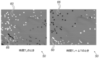
図2は、本発明の一実施形態による、心室解剖図50の一部分に重ね合わせられた、2つの連続する時間での、双極心臓内電位図(EGM)活性化型のドットマッピング可視化を示すボリュームレンダリングを抜粋したものである。
Visual Distinction of Primary and Secondary Activation in Electrophysiological Maps FIG. 2 is an excerpt of a volume rendering showing dot mapping visualization of bipolar intracardiac electrogram (EGM) activation types at two successive times, superimposed on a portion of a
図2は、解剖学的マップに重ね合わせられた双極心臓内EGM活性化の型に従う、双極心臓内EGM信号の表面表現の表示された映像(例えば、システム20のディスプレイ48に表示される映像)からの、時間T0及びT0+ΔTでとった、2つの画面キャプチャを示す。図2に示されるように、キャプチャした一次パターン及び異常パターンは、典型的に数分の1秒程度である時間ステップΔTの範囲で変化する。
2 shows two screen captures taken at times T0 and T0 + ΔT from a displayed image (e.g., the image displayed on
図2では、ドット60及び66によって視覚化された、解析された活性化は、プロセッサ40によってグレースケールの解剖学的マップ上に重ね合わせられ、ドット60及び66の色は、ドット位置における双極心臓内EGM活性化型の指示を与える。図2では、白色ドット60は、一次活性化を指し、一方で、黒いドット66は、二次の異常な活性化を示す。
In FIG. 2, the analyzed activation, visualized by
いくつかの実施形態では、開示されるように双極心臓内EGM信号を視覚化するために、プロセッサ40は、以下の工程を適用することによって、双極心臓内EGM信号を解析する。
(i)双極心臓内EGM信号を事前にフィルタ処理し、定常基線を取得した後に、双極心臓内EGM信号のノイズレベルを選択する。
(ii)ピークが選択されたノイズレベルを超えたときには常に、双極心臓内EGM信号の絶対値の極大値に、活性化としてラベル付けする。
(iii)心拍毎に、所与の可視化ウインドウスケール上で、双極心臓内EGMの最大絶対値を有する活性化に、一次活性化としてラベル付けし、他の活性化に、二次活性化としてラベル付けする。
(iv)最初の視覚的インジケータ(例えば、黒色ドット)を心臓マップ上に配置し、最初の視覚的インジケータを、一次活性化を示す位置のための第1の視覚的インジケータ(例えば、白色ドット)に、又は二次活性化を示す位置のための第2の視覚的インジケータ(例えば、青色ドット)(又は医師が選択する任意の色若しくは形状)に変化させる。
In some embodiments, to visualize the bipolar intracardiac EGM signal as disclosed, the
(i) Selecting the noise level of the bipolar intracardiac EGM signal after pre-filtering the bipolar intracardiac EGM signal and obtaining a constant baseline.
(ii) Local maxima in the absolute value of the bipolar intracardiac EGM signal are labeled as activations whenever the peaks exceed a selected noise level.
(iii) For each beat, the activation with the largest absolute value of the bipolar intracardiac EGM on a given visualization window scale is labeled as the primary activation, and the other activation is labeled as the secondary activation.
(iv) placing an initial visual indicator (e.g., a black dot) on the cardiac map and changing the initial visual indicator to a first visual indicator (e.g., a white dot) for locations indicating primary activation or to a second visual indicator (e.g., a blue dot) for locations indicating secondary activation (or any color or shape selected by the physician);
いくつかの実施形態では、ノイズレベルは、信号の特定のパーセンタイルに従って、プロセッサ40によって動的に設定することができる(例えば、ノイズレベルは、双極心臓内EGM信号の最後の10秒のスライディングウインドウ内の双極心臓内EGMの絶対値の10番目のパーセンタイルとして設定することができる)。ノイズレベルは、定数を乗算した(例えば、最後の10秒のスライディングウインドウにわたる標準偏差に2を掛ける)、スライディングウインドウにわたる双極心臓内EGM信号の絶対値の標準偏差に従って、動的に設定することができる。一次活性化の特定のパーセンテージと少なくとも同程度の高さ(例えば、一次活性化の90%)の活性化を、一次活性化とみなすことができる。一次活性化及び二次活性化が、非常に類似した時間に発生した場合、すなわち、所与の数ミリ秒(例えば、25ミリ秒)の以内で一致した場合、二次活性化は、一次(すなわち、一次活性化波形の特徴)とみなすことができる。
In some embodiments, the noise level can be dynamically set by the
一実施形態では、双極心臓内EGM信号の絶対値の代わりに、プロセッサは、信号の一次導関数を確認することができる。次いで、プロセッサは、導関数の最大絶対値を探して、一次活性化と二次活性化とを区別する。 In one embodiment, instead of the absolute value of the bipolar intracardiac EGM signal, the processor can look at the first derivative of the signal. The processor then looks for the maximum absolute value of the derivative to distinguish between primary and secondary activation.
いくつかの実施形態では、一次活性化又は二次活性化が双極心臓内EGM波形のQRS群と一致した場合は、異なる色とすることができる。「QRSと一致する」という定義は、それぞれのR波ピークから数ミリ秒以内の所定の範囲内とすることができる。代替的に、QRS群を検出することができ、QRS時間間隔全体を考慮することができる。任意に、ユーザは、QRS群の周囲の数ミリ秒の範囲を指定することができる。例えば、プロセッサは、QRS群の5ミリ秒後まで、QRSの開始5ミリ秒前の間隔と一致する黄色ドットに色付けすることができる。 In some embodiments, primary or secondary activations may be a different color if they coincide with the QRS complex of a bipolar intracardiac EGM waveform. The definition of "coincident with QRS" may be within a predetermined range of a few milliseconds from the respective R-wave peak. Alternatively, the QRS complex may be detected and the entire QRS time interval may be considered. Optionally, the user may specify a range of a few milliseconds around the QRS complex. For example, the processor may color a yellow dot that coincides with the interval 5 milliseconds before the onset of the QRS up to 5 milliseconds after the QRS complex.
一実施形態では、一次活性化又は二次活性化がペーシングピークと一致する場合、一次活性化又は二次活性化は、異なる色とすることができる。「ペーシングピークと一致する」という定義は、ペーシングピークのタイミングを中心に所与の数ミリ秒の範囲内に発生する一次活性化又は二次活性化として与えることができる。 In one embodiment, if a primary or secondary activation coincides with a pacing peak, the primary or secondary activation may be a different color. A definition of "coinciding with a pacing peak" may be given as a primary or secondary activation occurring within a given range of a few milliseconds around the timing of the pacing peak.
図2に示される例示的なドットマッピング可視化は、単に概念を明確にする目的で選択されている。別の形状(例えば、ダイヤモンド形状)を使用して活性化を表すこと、ドット60及び66を詳細に視認するために拡大鏡効果を使用すること、及びその他などの、さまざまな追加的な可視化ツールを適用することができる。
The exemplary dot mapping visualization shown in FIG. 2 has been chosen solely for the purposes of conceptual clarity. Various additional visualization tools can be applied, such as using different shapes (e.g., diamond shapes) to represent activation, using a magnifying glass effect to view
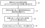
図3は、本発明の一実施形態による、図2に示される双極心臓内電位図(EGM)活性型のドットマッピング可視化のための方法を概略的に例示するフローチャートである。アルゴリズムは、提示された実施形態に従って、双極心臓内EGM活性化型割り当て工程70において、プロセッサ40が、上に記載したステップ(i)~(iv)を使用して解析された双極心臓内EGM活性化型を、心室50のラットマップ表面にわたるなどの、心室の解剖学的マップにわたるそれぞれの位置に割り当てることから始まる過程を実行する。
Figure 3 is a flow chart that generally illustrates a method for dot mapping visualization of the bipolar intracardiac electrogram (EGM) activation types shown in Figure 2, according to an embodiment of the present invention. The algorithm executes a process that begins with the
次に、形状及び色選択工程72で、プロセッサ40は、活性化の型に従って、幾何学的形状及び形状色(例えば、一次のために白色、二次のために青色)を選択する。次に、双極心臓内EGM活性化データ点の重ね合わせ工程74で、プロセッサ40は、各解析された位置の活性化型に従って、色分けされた形状を解剖学的マップに重ね合わせる。最後に、マップ表示工程76で、プロセッサ40は、結果として生じる可視化(例えば、図2のドット60及び66などの、活性化型に従って色付けした、重ね合わせられたドットを含むLATマップ)をディスプレイ48上で医師28に提示する。
Next, in a shape and
図3に示される例示的なフローチャートは、単に概念を明確にする目的で選択されている。本実施形態は、アルゴリズムの追加的な工程も含む。その例としては、ドット60と66との間の伝導矢印などの追加的な可視化が挙げられる。かかる追加的なステップは、より単純化されたフローチャートを提供するために、本明細書の開示から意図的に取り除かれている。
The exemplary flow chart shown in FIG. 3 has been selected solely for the purposes of conceptual clarity. This embodiment also includes additional steps of the algorithm, such as additional visualizations, such as a conducting arrow between
本明細書に記載されている実施形態は、主として心臓マッピングを対象にしたものであるが、本明細書に記載される方法お及びシステムは、脳組織のEPマッピングなどの他の用途にも使用することができる。 Although the embodiments described herein are directed primarily to cardiac mapping, the methods and systems described herein may also be used for other applications, such as EP mapping of brain tissue.
上に述べた実施形態は例として挙げたものであり、本発明は上述に具体的に示し説明したものに限定されない点が理解されよう。むしろ本発明の範囲は、上述のさまざまな特徴の組み合わせ及びその一部の組み合わせの両方、並びに上述の説明を読むことで当業者により想到されるであろう、また従来技術において開示されていないそれらの変形及び修正を含むものである。参照により本特許出願に援用される文献は、これらの援用文献において、いずれかの用語が本明細書において明示的又は暗示的になされた定義と矛盾して定義されている場合には、本明細書における定義のみを考慮するものとする点を除き、本出願の一部とみなすものとする。 It will be understood that the above-described embodiments are given by way of example, and that the present invention is not limited to what has been specifically shown and described above. Rather, the scope of the present invention includes both combinations and subcombinations of the various features described above, as well as variations and modifications thereof that would occur to one skilled in the art upon reading the above description and that are not disclosed in the prior art. Documents incorporated by reference into this patent application are to be considered as part of this application, except that if any term is defined in such incorporated documents in a manner that is inconsistent with the definition expressly or impliedly given herein, then only the definition in this specification shall be considered.
〔実施の態様〕
(1) 方法であって、
心臓の少なくとも一部分の解剖学的マップを受信することと、
前記解剖学的マップの少なくとも1つの領域について、位置及び前記位置で測定されたそれぞれの双極心臓内電位図(EGM)信号を受信することと、
前記双極心臓内EGM信号において、一次活性化及び二次活性化を識別することと、
識別された前記一次活性化及び前記二次活性化を含む、前記領域上の前記双極心臓内EGM信号の表面表現を導出することと、
前記解剖学的マップに重ね合わせられた前記表面表現を提示することと、を含む、方法。
(2) 前記表面表現を提示することが、視覚的インジケータの第1の型を使用して前記一次活性化を提示することと、視覚的インジケータの第2の型を使用して前記二次活性化を提示することと、を含む、実施態様1に記載の方法。
(3) 前記視覚的インジケータの前記第1及び第2の型が、第1及び第2の異なる幾何学的形状を含む、実施態様2に記載の方法。
(4) 前記視覚的インジケータの前記第1及び第2の型が、第1及び第2の異なる色を有する、実施態様2に記載の方法。
(5) 前記視覚的インジケータの前記第1及び第2の型が、局所活性化時間(LAT)を表す、実施態様2に記載の方法。
[Embodiment]
(1) A method comprising the steps of:
receiving an anatomical map of at least a portion of the heart;
receiving locations and respective bipolar intracardiac electrogram (EGM) signals measured at said locations for at least one region of said anatomical map;
identifying primary and secondary activation in the bipolar intracardiac EGM signal;
deriving a surface representation of the bipolar intracardiac EGM signal over the region including the identified primary and secondary activations;
presenting the surface representation superimposed on the anatomical map.
2. The method of claim 1, wherein presenting the surface representation comprises presenting the primary activation using a first type of visual indicator and presenting the secondary activation using a second type of visual indicator.
3. The method of claim 2, wherein the first and second types of visual indicators comprise first and second different geometric shapes.
4. The method of claim 2, wherein the first and second types of visual indicators have first and second distinct colors.
5. The method of claim 2, wherein the first and second types of visual indicators represent local activation times (LAT).
(6) 前記双極心臓内EGM信号の中の1つの双極心臓内EGM信号の前記一次活性化及び前記二次活性化を識別することが、
前記双極心臓内EGM信号のノイズレベルを選択することと、
選択された前記ノイズレベルを超える前記双極心臓内EGM信号の極大値に、活性化としてラベル付けすることと、
所与の心周期にわたって、最大絶対値を有する活性化に、一次活性化としてラベル付けし、かつ他の活性化に、二次活性化としてラベル付けすることと、を含む、実施態様1に記載の方法。
(7) システムであって、
心臓の少なくとも一部分の解剖学的マップを記憶するように構成されたメモリと、
プロセッサと、を備え、前記プロセッサは、
前記解剖学的マップの少なくとも1つの領域について、位置及び前記位置で測定されたそれぞれの双極心臓内電位図(EGM)信号を受信するように、
前記双極心臓内EGM信号において、一次活性化及び二次活性化を識別するように、
識別された前記一次活性化及び前記二次活性化を含む、前記領域上の前記双極心臓内EGM信号の表面表現を導出するように、かつ
前記解剖学的マップに重ね合わせられた前記表面表現を提示するように構成されている、システム。
(8) 前記プロセッサが、視覚的インジケータの第1の型を使用して前記一次活性化を提示することと、視覚的インジケータの第2の型を使用して前記二次活性化を提示することとによって、前記表面表現を提示するように構成されている、実施態様7に記載のシステム。
(9) 前記視覚的インジケータの型の前記第1及び第2の型が、第1及び第2の異なる幾何学的形状を含む、実施態様8に記載のシステム。
(10) 前記視覚的インジケータの型の前記第1及び第2の型が、第1及び第2の異なる色を有する、実施態様8に記載のシステム。
(6) identifying the primary activation and the secondary activation of a bipolar intracardiac EGM signal among the bipolar intracardiac EGM signals,
selecting a noise level for said bipolar intracardiac EGM signal;
labeling as activations local maxima of the bipolar intracardiac EGM signal that exceed the selected noise level;
2. The method of claim 1, comprising labeling the activation having the largest absolute value as the primary activation and labeling other activations as secondary activations over a given cardiac cycle.
(7) A system comprising:
a memory configured to store an anatomical map of at least a portion of the heart;
a processor, the processor comprising:
receiving, for at least one region of the anatomical map, locations and respective bipolar intracardiac electrogram (EGM) signals measured at the locations;
identifying primary and secondary activation in the bipolar intracardiac EGM signal;
derive a surface representation of the bipolar intracardiac EGM signal over the region including the identified primary and secondary activations; and present the surface representation superimposed on the anatomical map.
8. The system of claim 7, wherein the processor is configured to present the surface representation by presenting the primary activation using a first type of visual indicator and presenting the secondary activation using a second type of visual indicator.
9. The system of claim 8, wherein the first and second types of visual indicators include first and second different geometric shapes.
10. The system of claim 8, wherein the first and second types of visual indicators have first and second different colors.
(11) 前記視覚的インジケータの前記第1及び第2の型が、局所活性化時間(LAT)を表す、実施態様8に記載のシステム。
(12) 前記プロセッサが、前記双極心臓内EGM信号の中の1つの双極心臓内EGM信号の前記一次活性化及び前記二次活性化を、
前記双極心臓内EGM信号のノイズレベルを選択することと、
選択された前記ノイズレベルを超える前記双極心臓内EGM信号の極大値に、活性化としてラベル付けすることと、
所与の心周期にわたって、最大絶対値を有する活性化に、一次活性化としてラベル付けし、かつ他の活性化に、二次活性化としてラベル付けすることと、
によって、識別するように構成されている、実施態様7に記載のシステム。
11. The system of claim 8, wherein the first and second types of visual indicators represent local activation times (LAT).
(12) The processor further comprises:
selecting a noise level for said bipolar intracardiac EGM signal;
labeling as activations local maxima of the bipolar intracardiac EGM signal that exceed the selected noise level;
labeling the activation having the largest absolute value as the primary activation and the other activation as the secondary activation over a given cardiac cycle;
The system of claim 7, wherein the system is configured to identify the
Claims (10)
前記プロセッサが、心臓の少なくとも一部分の解剖学的マップを受信することと、
前記解剖学的マップの少なくとも1つの領域について、前記プロセッサが、位置及び前記位置で測定されたそれぞれの双極心臓内電位図(EGM)信号を受信することと、
前記双極心臓内EGM信号において、前記プロセッサが、一次活性化及び二次活性化を識別することと、
前記プロセッサが、前記双極心臓内EGM信号の中の1つの双極心臓内EGM信号の前記一次活性化及び前記二次活性化を識別することが、
(i)前記プロセッサが、前記双極心臓内EGM信号のノイズレベルを選択することと、
(ii)前記プロセッサが、選択された前記ノイズレベルを超える前記双極心臓内EGM信号の極大値に、活性化としてラベル付けすることと、
(iii)前記プロセッサが、前記活性化としてラベル付けされた前記極大値のうち、所与の心周期にわたって、最大絶対値を有する極大値に、一次活性化としてラベル付けし、かつ他の極大値に、二次活性化としてラベル付けすることと、を含み、
前記プロセッサが、識別された前記一次活性化及び前記二次活性化を含む、前記領域上の前記双極心臓内EGM信号の表面表現を導出することと、
前記プロセッサが、前記解剖学的マップに重ね合わせられた前記表面表現を提示することと、を含む、システムの作動方法。 1. A method of operating a system including a processor, comprising :
receiving an anatomical map of at least a portion of a heart ;
for at least one region of the anatomical map, the processor receiving locations and respective bipolar intracardiac electrogram (EGM) signals measured at the locations;
identifying , by the processor, primary and secondary activation in the bipolar intracardiac EGM signal;
the processor identifying the primary activation and the secondary activation of a bipolar intracardiac EGM signal among the bipolar intracardiac EGM signals;
(i) the processor selecting a noise level for the bipolar intracardiac EGM signal;
(ii) the processor labeling as activations local maxima of the bipolar intracardiac EGM signal that exceed the selected noise level;
(iii) the processor labels, among the maxima labeled as activations, a local maximum having a largest absolute value over a given cardiac cycle as a primary activation and labels other local maxima as secondary activations;
the processor deriving a surface representation of the bipolar intracardiac EGM signal over the region including the identified primary activation and the secondary activation;
and wherein the processor presents the surface representation superimposed on the anatomical map.
心臓の少なくとも一部分の解剖学的マップを記憶するように構成されたメモリと、
プロセッサと、を備え、前記プロセッサは、
前記解剖学的マップの少なくとも1つの領域について、位置及び前記位置で測定されたそれぞれの双極心臓内電位図(EGM)信号を受信するように、
前記双極心臓内EGM信号において、一次活性化及び二次活性化を識別するように、
識別された前記一次活性化及び前記二次活性化を含む、前記領域上の前記双極心臓内EGM信号の表面表現を導出するように、かつ
前記解剖学的マップに重ね合わせられた前記表面表現を提示するように構成され、
前記プロセッサが、さらに、前記双極心臓内EGM信号の中の1つの双極心臓内EGM信号の前記一次活性化及び前記二次活性化を、
(i)前記双極心臓内EGM信号のノイズレベルを選択することと、
(ii)選択された前記ノイズレベルを超える前記双極心臓内EGM信号の極大値に、活性化としてラベル付けすることと、
(iii)前記活性化としてラベル付けされた前記極大値のうち、所与の心周期にわたって、最大絶対値を有する極大値に、一次活性化としてラベル付けし、かつ他の極大値に、二次活性化としてラベル付けすることと、
によって、識別するように構成されている、システム。 1. A system comprising:
a memory configured to store an anatomical map of at least a portion of the heart;
a processor, the processor comprising:
receiving, for at least one region of the anatomical map, locations and respective bipolar intracardiac electrogram (EGM) signals measured at the locations;
identifying primary and secondary activation in the bipolar intracardiac EGM signal;
deriving a surface representation of the bipolar intracardiac EGM signal over the region including the identified primary and secondary activations; and presenting the surface representation superimposed on the anatomical map ;
The processor further comprises: filtering the primary activation and the secondary activation of a bipolar intracardiac EGM signal among the bipolar intracardiac EGM signals;
(i) selecting a noise level for said bipolar intracardiac EGM signal;
(ii) labeling as activations local maxima of the bipolar intracardiac EGM signal that exceed the selected noise level;
(iii) labeling, among the maxima labeled as activations, a maximum having a largest absolute value over a given cardiac cycle as a primary activation and labeling other maxima as secondary activations;
A system configured to identify a
Applications Claiming Priority (2)
| Application Number | Priority Date | Filing Date | Title |
|---|---|---|---|
| US16/437,090 US11344245B2 (en) | 2019-06-11 | 2019-06-11 | Visually differentiating primary and secondary activations on electrophysiological maps |
| US16/437,090 | 2019-06-11 |
Publications (2)
| Publication Number | Publication Date |
|---|---|
| JP2020199265A JP2020199265A (en) | 2020-12-17 |
| JP7588970B2 true JP7588970B2 (en) | 2024-11-25 |
Family
ID=71083473
Family Applications (1)
| Application Number | Title | Priority Date | Filing Date |
|---|---|---|---|
| JP2020100736A Active JP7588970B2 (en) | 2019-06-11 | 2020-06-10 | Visual Distinction of Primary and Secondary Activation in Electrophysiological Maps |
Country Status (5)
| Country | Link |
|---|---|
| US (1) | US11344245B2 (en) |
| EP (1) | EP3750478B1 (en) |
| JP (1) | JP7588970B2 (en) |
| CN (1) | CN112057039B (en) |
| IL (1) | IL275196B2 (en) |
Families Citing this family (6)
| Publication number | Priority date | Publication date | Assignee | Title |
|---|---|---|---|---|
| US11160485B2 (en) * | 2020-04-01 | 2021-11-02 | Biosense Webster (Israel) Ltd. | Propagation map of a heart chamber with areas demonstrating fractionated electrograms |
| US12539068B2 (en) * | 2020-04-21 | 2026-02-03 | St. Jude Medical, Cardiology Division, Inc. | System and method for mapping cardiac activity |
| US12082881B2 (en) * | 2021-03-22 | 2024-09-10 | Biosense Webster (Israel) Ltd. | Visualizing multiple parameters overlaid on an anatomical map |
| EP4626317A1 (en) * | 2022-12-01 | 2025-10-08 | Biosense Webster (Israel) Ltd. | Point of interest (poi) map for cardiac arrhythmia diagnosis |
| US12324669B2 (en) | 2022-12-21 | 2025-06-10 | Biosense Webster (Israel) Ltd. | Detecting local activation source in atrial fibrillation |
| US20250344983A1 (en) * | 2024-05-10 | 2025-11-13 | Biosense Webster (Israel) Ltd. | Cardiac map advanced ripple mode with gui |
Citations (4)
| Publication number | Priority date | Publication date | Assignee | Title |
|---|---|---|---|---|
| US20140180151A1 (en) | 2012-12-20 | 2014-06-26 | Boston Scientific Scimed, Inc. | Suppression of global activation signals during anatomical mapping |
| US20140236034A1 (en) | 2013-02-19 | 2014-08-21 | Biotronik Se & Co. Kg | Method for the detection of subcutanous cardiac signals and a cardiac device for use in detecting subcutaneous cardiac signals |
| JP2018502643A (en) | 2015-01-07 | 2018-02-01 | セント・ジュード・メディカル,カーディオロジー・ディヴィジョン,インコーポレイテッド | System, method, and apparatus for visualizing cardiac timing information using animation |
| JP2019506971A (en) | 2016-03-01 | 2019-03-14 | セント・ジュード・メディカル,カーディオロジー・ディヴィジョン,インコーポレイテッド | Method and system for mapping cardiac activity |
Family Cites Families (12)
| Publication number | Priority date | Publication date | Assignee | Title |
|---|---|---|---|---|
| US7907994B2 (en) * | 2007-01-11 | 2011-03-15 | Biosense Webster, Inc. | Automated pace-mapping for identification of cardiac arrhythmic conductive pathways and foci |
| US8478388B2 (en) | 2009-04-07 | 2013-07-02 | Pacesetter, Inc. | Cardiac coordinate system for motion analysis |
| US10918298B2 (en) | 2009-12-16 | 2021-02-16 | The Board Of Trustees Of The University Of Illinois | High-speed, high-resolution electrophysiology in-vivo using conformal electronics |
| US8948837B2 (en) * | 2011-01-13 | 2015-02-03 | Rhythmia Medical, Inc. | Electroanatomical mapping |
| US8897516B2 (en) | 2011-03-16 | 2014-11-25 | Biosense Webster (Israel) Ltd. | Two-dimensional cardiac mapping |
| US9050011B2 (en) | 2012-12-26 | 2015-06-09 | Biosense Webster (Israel) Ltd. | Removal of artifacts from map data |
| US9814406B2 (en) | 2013-11-19 | 2017-11-14 | Pacesetter, Inc. | Method and system to identify motion data associated with consistent electrical and mechanical behavior for a region of interest |
| US10925511B2 (en) | 2014-07-24 | 2021-02-23 | Cardiosolv Ablation Technologies, Inc. | System and method for cardiac ablation |
| US9955889B2 (en) * | 2014-11-03 | 2018-05-01 | Biosense Webster (Israel) Ltd. | Registration maps using intra-cardiac signals |
| US9949657B2 (en) * | 2015-12-07 | 2018-04-24 | Biosense Webster (Israel) Ltd. | Displaying multiple-activation areas on an electroanatomical map |
| US10136828B2 (en) * | 2016-03-31 | 2018-11-27 | Biosense Webster (Israel) Ltd. | Mapping of atrial fibrillation |
| CN110622254B (en) * | 2017-05-17 | 2024-04-05 | 圣犹达医疗用品心脏病学部门有限公司 | System and method for mapping local activation times |
-
2019
- 2019-06-11 US US16/437,090 patent/US11344245B2/en active Active
-
2020
- 2020-06-07 IL IL275196A patent/IL275196B2/en unknown
- 2020-06-10 EP EP20179139.9A patent/EP3750478B1/en active Active
- 2020-06-10 JP JP2020100736A patent/JP7588970B2/en active Active
- 2020-06-11 CN CN202010528304.0A patent/CN112057039B/en active Active
Patent Citations (4)
| Publication number | Priority date | Publication date | Assignee | Title |
|---|---|---|---|---|
| US20140180151A1 (en) | 2012-12-20 | 2014-06-26 | Boston Scientific Scimed, Inc. | Suppression of global activation signals during anatomical mapping |
| US20140236034A1 (en) | 2013-02-19 | 2014-08-21 | Biotronik Se & Co. Kg | Method for the detection of subcutanous cardiac signals and a cardiac device for use in detecting subcutaneous cardiac signals |
| JP2018502643A (en) | 2015-01-07 | 2018-02-01 | セント・ジュード・メディカル,カーディオロジー・ディヴィジョン,インコーポレイテッド | System, method, and apparatus for visualizing cardiac timing information using animation |
| JP2019506971A (en) | 2016-03-01 | 2019-03-14 | セント・ジュード・メディカル,カーディオロジー・ディヴィジョン,インコーポレイテッド | Method and system for mapping cardiac activity |
Also Published As
| Publication number | Publication date |
|---|---|
| EP3750478A1 (en) | 2020-12-16 |
| IL275196A (en) | 2020-12-31 |
| CN112057039A (en) | 2020-12-11 |
| EP3750478B1 (en) | 2023-06-07 |
| US11344245B2 (en) | 2022-05-31 |
| EP3750478C0 (en) | 2023-06-07 |
| IL275196B1 (en) | 2023-03-01 |
| CN112057039B (en) | 2025-09-05 |
| JP2020199265A (en) | 2020-12-17 |
| IL275196B2 (en) | 2023-07-01 |
| US20200390353A1 (en) | 2020-12-17 |
Similar Documents
| Publication | Publication Date | Title |
|---|---|---|
| JP7588970B2 (en) | Visual Distinction of Primary and Secondary Activation in Electrophysiological Maps | |
| AU2015261709B2 (en) | Differential mapping of a body organ | |
| EP2982293A1 (en) | Wavefront analysis based on ablation parameters | |
| US8620417B2 (en) | Graphic user interface for physical parameter mapping | |
| JP7676179B2 (en) | Ventricular propagation map with areas showing segmented electrograms | |
| JP7588982B2 (en) | Re-annotation of electroanatomical maps | |
| IL289283A (en) | Incorporating a confidence level into an electrophysiological (ep) map | |
| CN112842353A (en) | Mapping local activation times of sinus and non-sinus cardiac cycles | |
| EP3614913B1 (en) | Connectivity analysis for arrhythmia drivers | |
| EP3669772B1 (en) | Electrophysiological ripple mapping visualization method | |
| EP4079217A1 (en) | Improved electrophysiological (ep) map coloration by considering outliers | |
| EP4518761B1 (en) | Detecting potential slow-conduction cardiac tissue areas in stable arrhythmias | |
| US20240285216A1 (en) | Local ecg annotation visualization | |
| EP4599768A1 (en) | Local ecg annotation visualization |
Legal Events
| Date | Code | Title | Description |
|---|---|---|---|
| A621 | Written request for application examination |
Free format text: JAPANESE INTERMEDIATE CODE: A621 Effective date: 20230609 |
|
| A977 | Report on retrieval |
Free format text: JAPANESE INTERMEDIATE CODE: A971007 Effective date: 20240315 |
|
| A131 | Notification of reasons for refusal |
Free format text: JAPANESE INTERMEDIATE CODE: A131 Effective date: 20240423 |
|
| A521 | Request for written amendment filed |
Free format text: JAPANESE INTERMEDIATE CODE: A523 Effective date: 20240716 |
|
| TRDD | Decision of grant or rejection written | ||
| A01 | Written decision to grant a patent or to grant a registration (utility model) |
Free format text: JAPANESE INTERMEDIATE CODE: A01 Effective date: 20241015 |
|
| A61 | First payment of annual fees (during grant procedure) |
Free format text: JAPANESE INTERMEDIATE CODE: A61 Effective date: 20241113 |
|
| R150 | Certificate of patent or registration of utility model |
Ref document number: 7588970 Country of ref document: JP Free format text: JAPANESE INTERMEDIATE CODE: R150 |