JP7588960B2 - Imaging device - Google Patents
Imaging device Download PDFInfo
- Publication number
- JP7588960B2 JP7588960B2 JP2020032453A JP2020032453A JP7588960B2 JP 7588960 B2 JP7588960 B2 JP 7588960B2 JP 2020032453 A JP2020032453 A JP 2020032453A JP 2020032453 A JP2020032453 A JP 2020032453A JP 7588960 B2 JP7588960 B2 JP 7588960B2
- Authority
- JP
- Japan
- Prior art keywords
- vibration
- mode
- shooting
- vibration device
- release button
- Prior art date
- Legal status (The legal status is an assumption and is not a legal conclusion. Google has not performed a legal analysis and makes no representation as to the accuracy of the status listed.)
- Active
Links
Images


Classifications
-
- G—PHYSICS
- G03—PHOTOGRAPHY; CINEMATOGRAPHY; ANALOGOUS TECHNIQUES USING WAVES OTHER THAN OPTICAL WAVES; ELECTROGRAPHY; HOLOGRAPHY
- G03B—APPARATUS OR ARRANGEMENTS FOR TAKING PHOTOGRAPHS OR FOR PROJECTING OR VIEWING THEM; APPARATUS OR ARRANGEMENTS EMPLOYING ANALOGOUS TECHNIQUES USING WAVES OTHER THAN OPTICAL WAVES; ACCESSORIES THEREFOR
- G03B17/00—Details of cameras or camera bodies; Accessories therefor
- G03B17/02—Bodies
-
- G—PHYSICS
- G06—COMPUTING OR CALCULATING; COUNTING
- G06F—ELECTRIC DIGITAL DATA PROCESSING
- G06F3/00—Input arrangements for transferring data to be processed into a form capable of being handled by the computer; Output arrangements for transferring data from processing unit to output unit, e.g. interface arrangements
- G06F3/01—Input arrangements or combined input and output arrangements for interaction between user and computer
- G06F3/016—Input arrangements with force or tactile feedback as computer generated output to the user
-
- G—PHYSICS
- G06—COMPUTING OR CALCULATING; COUNTING
- G06F—ELECTRIC DIGITAL DATA PROCESSING
- G06F3/00—Input arrangements for transferring data to be processed into a form capable of being handled by the computer; Output arrangements for transferring data from processing unit to output unit, e.g. interface arrangements
- G06F3/01—Input arrangements or combined input and output arrangements for interaction between user and computer
- G06F3/03—Arrangements for converting the position or the displacement of a member into a coded form
- G06F3/033—Pointing devices displaced or positioned by the user, e.g. mice, trackballs, pens or joysticks; Accessories therefor
- G06F3/0362—Pointing devices displaced or positioned by the user, e.g. mice, trackballs, pens or joysticks; Accessories therefor with detection of 1D translations or rotations of an operating part of the device, e.g. scroll wheels, sliders, knobs, rollers or belts
-
- H—ELECTRICITY
- H04—ELECTRIC COMMUNICATION TECHNIQUE
- H04N—PICTORIAL COMMUNICATION, e.g. TELEVISION
- H04N23/00—Cameras or camera modules comprising electronic image sensors; Control thereof
- H04N23/50—Constructional details
- H04N23/51—Housings
-
- H—ELECTRICITY
- H04—ELECTRIC COMMUNICATION TECHNIQUE
- H04N—PICTORIAL COMMUNICATION, e.g. TELEVISION
- H04N23/00—Cameras or camera modules comprising electronic image sensors; Control thereof
- H04N23/60—Control of cameras or camera modules
- H04N23/63—Control of cameras or camera modules by using electronic viewfinders
- H04N23/631—Graphical user interfaces [GUI] specially adapted for controlling image capture or setting capture parameters
- H04N23/632—Graphical user interfaces [GUI] specially adapted for controlling image capture or setting capture parameters for displaying or modifying preview images prior to image capturing, e.g. variety of image resolutions or capturing parameters
-
- H—ELECTRICITY
- H04—ELECTRIC COMMUNICATION TECHNIQUE
- H04N—PICTORIAL COMMUNICATION, e.g. TELEVISION
- H04N23/00—Cameras or camera modules comprising electronic image sensors; Control thereof
- H04N23/60—Control of cameras or camera modules
- H04N23/667—Camera operation mode switching, e.g. between still and video, sport and normal or high- and low-resolution modes
-
- H—ELECTRICITY
- H04—ELECTRIC COMMUNICATION TECHNIQUE
- H04N—PICTORIAL COMMUNICATION, e.g. TELEVISION
- H04N23/00—Cameras or camera modules comprising electronic image sensors; Control thereof
- H04N23/70—Circuitry for compensating brightness variation in the scene
- H04N23/73—Circuitry for compensating brightness variation in the scene by influencing the exposure time
-
- H—ELECTRICITY
- H04—ELECTRIC COMMUNICATION TECHNIQUE
- H04N—PICTORIAL COMMUNICATION, e.g. TELEVISION
- H04N23/00—Cameras or camera modules comprising electronic image sensors; Control thereof
- H04N23/95—Computational photography systems, e.g. light-field imaging systems
- H04N23/958—Computational photography systems, e.g. light-field imaging systems for extended depth of field imaging
- H04N23/959—Computational photography systems, e.g. light-field imaging systems for extended depth of field imaging by adjusting depth of field during image capture, e.g. maximising or setting range based on scene characteristics
-
- H—ELECTRICITY
- H04—ELECTRIC COMMUNICATION TECHNIQUE
- H04N—PICTORIAL COMMUNICATION, e.g. TELEVISION
- H04N23/00—Cameras or camera modules comprising electronic image sensors; Control thereof
- H04N23/60—Control of cameras or camera modules
- H04N23/62—Control of parameters via user interfaces
Landscapes
- Engineering & Computer Science (AREA)
- General Engineering & Computer Science (AREA)
- Multimedia (AREA)
- Signal Processing (AREA)
- Theoretical Computer Science (AREA)
- Human Computer Interaction (AREA)
- Physics & Mathematics (AREA)
- General Physics & Mathematics (AREA)
- Computing Systems (AREA)
- Studio Devices (AREA)
- Camera Bodies And Camera Details Or Accessories (AREA)
- Apparatuses For Generation Of Mechanical Vibrations (AREA)
Description
本発明は、振動デバイスを有するデジタルカメラ、等々の撮像装置に関する。 The present invention relates to imaging devices such as digital cameras that have a vibration device.
近年、美術館などの雑音を気にする静かな環境下でも撮影したい要望が増えている。 In recent years, there has been an increasing demand for shooting in quiet environments where noise is a concern, such as museums.
一般的に撮像装置はシャッタ機構を制御して撮影する機械シャッタ方式(以下、メカシャッタという)のため、ユーザは撮影時の機械シャッタの動作による振動や音が発生する。 Generally, imaging devices use a mechanical shutter system (hereafter referred to as a mechanical shutter) that controls the shutter mechanism to take pictures, so users experience vibrations and noise caused by the operation of the mechanical shutter when taking pictures.
それにより撮影した操作感を得られるが、静かな環境下では撮影をすることができない。 This gives you the feeling of being able to shoot, but you cannot shoot in a quiet environment.
そこで、最近ではメカシャッタに加え、撮像素子を電子的に制御して撮影する電子シャッタ方式(以下、電子シャッタという)を搭載した撮像装置が増えている。 As a result, in addition to mechanical shutters, there has been an increase in imaging devices equipped with an electronic shutter system (hereafter referred to as electronic shutter) that electronically controls the image sensor to capture images.
しかし、電子シャッタはメカシャッタの機構が動かないため無音で撮れる一方で、ユーザはメカシャッタで得ていた撮影した操作感を得ることができない。 However, while electronic shutters allow for silent shooting because the mechanical shutter mechanism does not move, users cannot get the same feeling of control when taking pictures as they do with a mechanical shutter.
特許文献1には、ユーザが入力操作を行うと、撮像装置内に配置した複数の振動デバイスを駆動することで、撮影した操作感をユーザに伝達する構成が開示されている。
しかし、特許文献1はメカシャッタで得ていた撮影した操作感を得るために、複数の振動デバイスを同時に駆動することで大きな振動を発生させる。
However, in
そのため、静かな環境下では振動デバイスの駆動音が騒音となる可能性がある。また、撮像装置はメカシャッタと電子シャッタの両方を搭載している場合が多くなっている。 As a result, the driving sound of the vibration device may become audible in a quiet environment. Also, imaging devices are increasingly equipped with both mechanical and electronic shutters.
そのため、ユーザが選択したシャッタ方式に応じて振動デバイスの振動制御を行わないと、ユーザがメカシャッタを選択し振動デバイスによる撮影した操作感が不要の場合でも、レリーズボタン操作時に振動デバイスを駆動させてしまう。 Therefore, if the vibration of the vibration device is not controlled according to the shutter method selected by the user, the vibration device will be activated when the release button is operated, even if the user selects a mechanical shutter and does not need the feeling of taking pictures using the vibration device.
つまり、メカシャッタの動作で発生した振動に、振動デバイスによる振動が加わることで、ユーザに違和感ある操作感を与えてしまう可能性がある。 In other words, the vibrations generated by the operation of the mechanical shutter, combined with the vibrations from the vibration device, may give the user an uncomfortable feeling when operating the device.
さらに、撮像装置は電子シャッタによる連写撮影枚数が秒間数十枚程度の高速撮影が可能になっている。 In addition, imaging devices are now capable of high-speed continuous shooting at several tens of frames per second using an electronic shutter.
そのため、単写撮影時と同じ振動パターンでユーザに撮影した操作感を与えると、連写の撮影間隔に対して振動デバイスによる振動間隔が遅れ、ユーザに違和感を与えてしまう可能性がある。 Therefore, if the user is given the sensation of taking a picture using the same vibration pattern as when taking a single shot, the interval between vibrations caused by the vibrating device may be delayed compared to the interval between shots when taking continuous shots, which may cause the user to feel uncomfortable.
そこで本発明の目的は、ユーザが選択した様々な撮影設定に応じて、適宜振動デバイスの振動パターンを変更する。 The object of the present invention is to appropriately change the vibration pattern of a vibration device according to various shooting settings selected by the user.
そして、静かな環境下での撮影に対応し、尚且つユーザに違和感ない撮影した操作感を与えることが可能な撮像装置を提供することである。 And the goal is to provide an imaging device that can handle shooting in a quiet environment and gives the user a natural feeling when shooting.
その課題を解決するために、本発明は、複数の撮影モードに切り替え可能な撮像装置において、レリーズボタンと、前記レリーズボタンに対するユーザーの操作に応じた触覚をユーザーに伝えるために前記撮像装置を振動させる振動デバイスと、前記振動デバイスの駆動を制御する複数の振動パターンを有する振動制御手段と、を備え、前記振動制御手段は、撮影モードが電子シャッタを用いた撮影を行うモードである場合において、連写する撮影の枚数が多いときは連写する撮影の枚数が少ないときに比べて、前記振動デバイスの振動継続時間を短く設定するよう構成したことを特徴とする。 In order to solve this problem, the present invention provides an imaging device switchable between a plurality of shooting modes, comprising a release button, a vibration device which vibrates the imaging device to convey to a user a tactile sensation in response to the user's operation of the release button, and a vibration control means having a plurality of vibration patterns which control the driving of the vibration device, wherein when the shooting mode is a mode for shooting using an electronic shutter, the vibration control means is configured to set the vibration duration of the vibration device to be shorter when a large number of shots are taken in continuous shooting than when a small number of shots are taken in continuous shooting .
本発明によれば、ユーザが選択した様々な撮影設定に応じて、適宜振動デバイスの振動パターンを変更する。 According to the present invention, the vibration pattern of the vibration device is appropriately changed according to various shooting settings selected by the user.
そのため、静かな環境下での撮影に対応し、尚且つユーザに違和感ない撮影した操作感を与えることを可能とする撮像装置を提供することができる。 As a result, it is possible to provide an imaging device that can handle shooting in a quiet environment and allows the user to feel comfortable when shooting.
(撮像装置の一例)
以下、本発明の実施の形態による撮像装置の一例について、図1~図6を参照して説明する。
(An example of an imaging device)
Hereinafter, an example of an imaging device according to an embodiment of the present invention will be described with reference to FIGS.
図1は、交換レンズを装着可能な撮像装置としてのレンズ交換式デジタルカメラ(以下、カメラという)の本体斜視図である。 Figure 1 is a perspective view of the main body of an interchangeable lens digital camera (hereafter referred to as the camera) that is an imaging device to which an interchangeable lens can be attached.
図1(a)はカメラ100の前面本体斜視図、図1(b)はカメラ100の背面本体斜視図である。図1(c)はカメラ100に装着する交換レンズ102の装着前の状態図である。図1(d)は振動デバイス109の内部構造を説明する図である。
Figure 1(a) is a perspective view of the front body of the
カメラ100の前面には、ユーザがカメラ100を把持するためにカメラ100の前方に突出するフロントグリップ202が設けられている。
The front of the
また、カメラ100の前面中央には、交換レンズ102を着脱可能とするマウント部107が設けられている。
In addition, a
交換レンズ102の外周には、回転操作リング103が設けられている。
A
回転操作リング103は、ユーザが交換レンズ102の光軸回りで回転操作可能であり、ユーザは、焦点位置や露出値等の撮像条件を変更する機能を回転操作リング103に割り当てることができる。
The
カメラ100の上面には、電源レバー104、モードダイアル105、レリーズボタン106を備える。
The top surface of the
電源レバー104は、ユーザのレバー操作により、カメラ100の電源オン/オフを切り替える操作手段である。
The
モードダイアル105は、ユーザの回転操作により各種撮像モードを切り替える操作手段である。
The
各種撮像モードには、シャッタ速度や絞り値等の撮像条件をユーザが任意に設定可能なマニュアル静止画撮像モード、自動で適正な露光量が得られるオート静止画撮像モードおよび動画を撮像するための動画撮像モード等がある。 The various imaging modes include a manual still image capture mode, which allows the user to set imaging conditions such as shutter speed and aperture value, an auto still image capture mode, which automatically obtains the appropriate exposure, and a video capture mode for capturing videos.
レリーズボタン106は、ユーザの押圧操作により撮像を開始する撮影開始操作手段(撮影入力手段)である。フロントグリップ202の内側には、後述する振動デバイス109が取り付けられている。
The
レリーズボタン106は、SW1で撮影準備動作を開始し、SW2で操作開始動作(露光開始)を指示する機能がある。
The
振動デバイス109は、例えばリニアアクチュエータ(LRA)タイプや圧電素子タイプの振動デバイスであり、振動強度(振幅)や振動周波数等の振動パラメータの可変設定が可能である。
The
振動デバイス109は、回転操作リング103、モードダイアル105およびレリーズボタン106等の操作部材のユーザ操作に応じて振動を発生する。
The
さらに、振動デバイス109は、振動パラメータを変更することで、様々な振動パターンの振動を発生させることができる。
Furthermore, the
カメラ100の背面には、背面操作部(操作手段)110と、表示部111とが設けられている。
The rear surface of the
カメラ100の電源がオン状態であり、静止画または動画撮像モードが設定されているとき、表示部111には、不図示の撮像素子に撮像されている被写体像の画像信号(スルー画像)が表示される。
When the
また、表示部111には、シャッタ速度や絞り値等の撮像条件を示す撮像パラメータが表示される。
The
そして、ユーザは表示部111の表示を見ながら背面操作部110を操作することによって撮像パラメータの設定値を変更することが可能である。
The user can change the settings of the imaging parameters by operating the
また、背面操作部110は、記録された撮像画像の再生を指示するための再生ボタン1101を含み、該再生ボタン1101をユーザが操作することで、撮像画像が表示部111に再生表示される。
The
また、背面操作部110は、動画撮影を指示するための動画ボタン1102を含み、該動画ボタン1102をユーザが操作することで、動画撮影の開始、そして停止を行う。
The
カメラ100のマウント部107には、電気接点群108を備えている。カメラ100は、マウント部107に装着された交換レンズ102との通信や電源供給は、電気接点群108を介して行われる。
The
(振動デバイス109の内部構造)
図1(d)は、フロントグリップ202の内側に取り付けられた振動デバイス109の内部構造を示している。
(Internal structure of the vibration device 109)
FIG. 1D shows the internal structure of the
LRA(リニアレゾナントアクチュエーター)タイプの振動デバイス109は、振動子109a、マグネット109b、バネ109c、コイル109dおよびベース109eにより構成されている。
The LRA (linear resonant actuator)
振動子109aは、マグネット109bを保持し、かつベース109eに対してバネ109cにより移動可能に結合されている。
The
コイル109dは、マグネット109bの近傍に配置され、システムシステム制御部115(図2参照)と電気的に接続される。
コイル109dは、システムシステム制御部115から電流を与えられることで電磁力を発生し、その電磁力とマグネット109bとの間の吸着力また反発力により振動子109aが往復運動し、振動デバイス109に振動が発生する。
When a current is applied to the
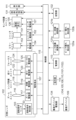
(カメラシステム全体のブロック図)
図2は、カメラ100の電気的および光学的な構成を示している。
(Block diagram of the entire camera system)
FIG. 2 shows the electrical and optical configuration of the
カメラ100は、後述する各部に電源を供給する電源部113と、前述した電源レバー104、モードダイアル105、レリーズボタン106および背面操作部110を含む操作部114とを有する。
The
カメラ100および交換レンズ102からなるカメラシステム全体の制御は、システム制御部115によって行われる。
The entire camera system consisting of the
この際、交換レンズ102は、前述した電気接点群107を介してシステム制御部115との通信を行う。
At this time, the
システム制御部115は、不図示のメモリに格納されている制御プログラムを読み出して実行することで、カメラシステム全体を制御する。
The
交換レンズ102は、光軸方向に移動して変倍を行うズームレンズを含むズームユニット116と、光軸に対して直交するX/Y軸方向に移動(シフト)して像振れを低減(補正)するシフトレンズを含むレンズ防振ユニット118とを有する。
The
また、交換レンズ102は、光量調節機能を有する絞りユニット122と、光軸方向に移動して焦点調節を行うフォーカスレンズを含むフォーカスユニット124とを有する。
The
さらに、交換レンズ102は、回転操作リング103の回転を検出する回転検出部133を有する。
Furthermore, the
システム制御部115は、回転操作リング103が操作されて回転検出部133を介して変倍の指示が入力される。
When the
その場合、交換レンズ102に設けられたズーム駆動部117を介してズームユニット116の駆動を制御することで変倍を行わせる。
In this case, the magnification is changed by controlling the drive of the
また、システム制御部115は、操作部114から受けた絞り値の設定値または画像処理部131から取得した輝度信号に応じて、交換レンズ102に設けられた絞り駆動部123を介して絞りユニット122の駆動を制御する。
In addition, the
また、システム制御部115は、画像処理部131から取得した焦点信号に応じて、交換レンズ102に設けられたフォーカス駆動部125を介してフォーカスユニット124の駆動を制御することで、オートフォーカスを行う。
In addition, the
カメラ100には、ピッチ防振演算部121aとヨー防振演算部121bが設けられている。
The
ピッチ防振演算部121aは、ピッチ振れ検出部120aからの振れ信号を用いてレンズ防振ユニット118(シフトレンズ)とセンサ防振ユニット130(撮像素子126)のY軸方向でのシフト位置を算出する。
The pitch vibration
また、ヨー防振演算部121bは、ヨー振れ検出部120bからの振れ信号を用いてレンズ防振ユニット118とセンサ防振ユニット130のX軸方向でのシフト位置を算出する。
The yaw vibration
カメラ100には、センサ防振ユニット130を駆動するセンサ駆動部127が設けられている。交換レンズ102には、レンズ防振ユニット118を駆動する防振駆動部119が設けられている。
The
システム制御部115は、ピッチおよびヨー防振演算部121a,121bが算出したピッチ/ヨー方向のシフト位置に応じて、レンズ防振ユニット118とセンサ防振ユニット130のシフト位置を制御する。
The
その場合、防振駆動部119とセンサ駆動部127を介してレンズ防振ユニット118とセンサ防振ユニット130のシフト位置を制御する。
In this case, the shift positions of the lens vibration isolation unit 118 and the sensor
これにより、像振れを補正する防振動作が行われる。 This performs an anti-shake operation to correct image shake.
カメラ100には、メインミラーとサブミラー(不図示)から成るミラーユニット153と、これを駆動するミラー駆動部154とを有する。
The
カメラ100には、機械式のフォーカルプレーンシャッタ(不図示)から成るシャッタユニット151と、これを駆動するシャッタ駆動部152とを有する。
The
また、システム制御部115は、レリーズボタン106による撮像指示操作に応じて、ミラー駆動部154とシャッタ駆動部152を介してシャッタユニット151とミラーユニット153の駆動を制御する。
In addition, the
これにより、交換レンズ102により形成された光学像が撮像素子126に露光され、撮像素子126によって光電変換され撮像信号として出力される。
As a result, the optical image formed by the
画像処理部131は、撮像信号に対して各種画像処理を行って画像信号を生成し、SDカードなどの記憶部132に記憶される。
The
表示部111は、画像処理部131から出力された画像信号(スルー画像)を表示したり、記憶部132に記録された撮像画像を再生表示したりする。
The
システム制御部115は、回転操作リング103や操作部114の操作を検出すると、振動デバイス駆動部134に振動デバイス109に対して駆動信号を出力し、振動デバイス109に振動を発生させる。
When the
このように、振動デバイス109が図1(a)に示したフロントグリップ202に振動を与える。
In this way, the
よって、フロントグリップ202を把持するユーザに対して回転操作リング103の回転操作に対するクリック感や操作部114の操作に対する操作感を与えることができる。
This allows the user holding the
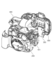
(カメラ100の各ユニットを展開した展開斜視図)
図3は、カメラ100の各ユニットを展開した展開斜視図である。
(Expanded perspective view of each unit of the camera 100)
FIG. 3 is an exploded perspective view of the
カメラ100は、内部構造体101とフロントカバーユニット200、上面カバーユニット400、リアカバーユニット500から構成され、システム制御部115は、該内部構造体101にビス締結されている。
The
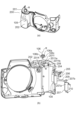
(フロントカバーユニット200)
図4(a)は、フロントカバーユニット200の前面斜視図であり、図4(b)はフロントカバーユニット200の背面分解斜視図である。
(Front cover unit 200)
4A is a front perspective view of the
フロントカバーユニット200は、外装カバーである樹脂製のフロントカバー201と、表層に弾性を有し、且つユーザが把持するためのフロントグリップ202を有する。
The
フロントグリップ202は、フロントカバー201の外側から組み付けられ、不図示の両面テープにより固定される。
The
レリーズボタン106の裏面には、該レリーズボタン106の押込方向(以下、R軸方向という)に延設された押し子106aと当接部106bを有する。
The back surface of the
レリーズボタン106の押し子106aには、Eリング204を装着する溝部106cを有する。
The
フロントカバー201は、レリーズボタン106を収容する収納部2011を有する。
The
フロントカバー201は、収納部2011にはレリーズボタン106の押し子106aと当接部106bがそれぞれ挿通する貫通孔2011aと2011bを有する。
The
レリーズボタン106は、フロントカバーの外側から収納部2011に組み込まれ、フロントカバー201の内側まで貫通してきた押し子106aの溝部106cにEリング204を組み込まれる。
The
撮影条件の設定変更や撮影の開始と終了を指示するレリーズボタン106は、Eリング204によりフロントカバー201に対する抜け止めとしている。
The
振動減衰部材208は矩形形状の部品で、ゴムやエラストマなど小さな力で大きく変形し、大きな弾性変形領域を持った材料で構成されている。
The
振動減衰部材208は、フロントカバー201の内側に備える台座2014に不図示の両面テープにより固定される。
The
レリーズボタン106の2段階押圧操作の検出は、押し込み量に応じて第1スイッチ(SW1)及び第2スイッチ(SW2)が順にオンするように構成された後述する3枚の接片(2051、2052、2053)から成るスイッチユニット205で行われる。
The two-stage pressing operation of the
スイッチユニット205には、複数の回路が配線されたフレキシブル基板209を有し、3枚の接片(2051、2052、2053)は、フレキシブル基板209の各回路とそれぞれ接触し電気的に接続されている。
The
さらに、フレキシブル基板209には、振動デバイス109を駆動するための各回路も配線され、振動デバイス109とフレキシブル基板209の各回路が電気的に接続されている。
Furthermore, the
フレキシブル基板209は、システム制御部115(図2参照)に接続される。スイッチユニット205は、フロントカバーの内側にビス206により固定される。
The
保持部品207には、振動デバイスを固定する基面207aと、基面207aから延設しR軸方向に弾性変形可能な振動伝搬部207bを有する。
The holding
振動デバイス109は、保持部品207の基面207aに不図示の両面テープにより固定される。
The
振動デバイス109が固定された保持部品207は、フロントカバーの内側にビス210により固定される。
The holding
撮影条件の設定変更や撮影の開始と終了を指示するレリーズボタン106が操作されていない状態(以下、通常状態)において、振動伝搬部207bは、振動減衰部材208に当接するように構成されている。
When the
上述のように、レリーズボタン106、スイッチユニット205、振動デバイス109を固定する保持部材207、振動減衰部材208は同一のフロントカバー201に固定される。
As described above, the
上述のようにフロントカバー201に部品を組み付けることで、組み付けによる組立公差を小さくすることができるので、関連部品の位置関係を容易に調整することが可能となる。
Assembling parts to the
図5(a)は、レリーズボタンの直上から見たフロントカバーユニット200を示し、図5(b)(c)(d)は、図5(a)中のA-A線とB-B線での断面を拡大して示す。
Figure 5(a) shows the
A-A線、B-B線は、それぞれレリーズボタン106の押し子106aの中心軸を通っている。
Lines A-A and B-B each pass through the central axis of the
図5の通常状態は、レリーズボタン106が押下されていない、すなわちレリーズボタン106が初期位置に位置する状態を示している。
The normal state in Figure 5 shows the state in which the
図5のSW1状態は、レリーズボタン106が押下され、第一のスイッチ(SW1)がオンとなる状態を示している。
The SW1 state in Figure 5 shows the state in which the
図5のSW2状態は、SW1状態からさらにレリーズボタン106が押下され、第二のスイッチ(SW2)がオンとなる状態を示している。
The SW2 state in Figure 5 shows the state in which the
スイッチユニット205は、フロントカバー201の内側にビス206で固定される。
The
スイッチユニット205は、レリーズボタン106側から第一の接片2051、第二の接片2052、第三の接片2053から構成され、各接片は互いに絶縁されている。
The
第一の接片2051の自由端は、レリーズボタン106の押し子106aの先端に圧接することで、レリーズボタン106を上方へ付勢する。
The free end of the
レリーズボタン106は、押し子106bの溝部106cに組み付けられたEリング204がフロントカバー201の収納部2011の下端に当接することで、レリーズボタン106のR軸方向の上方位置を規制する。
The
第二の接片2052と第三の接片2053の自由端は、フロントカバーの位置規制部2015、2016に当接することで、第二の接片2052と第三の接片2053の自由端のR軸方向の位置を規制する。
The free ends of the
図5(b)の通常状態からレリーズボタン106を第一の接片2051の弾性力に抗して押し込む。
From the normal state shown in Figure 5 (b), press the
よって、図5(b)SW1オン状態のように、第一の接片2051は弾性変形して第二の接片2052に接触し、第一のスイッチ(SW1)がオンとなる。
As a result, as shown in FIG. 5(b) in the SW1 ON state, the
第一スイッチ(SW1)がオンされると、フォーカス駆動部125がフォーカスユニット124を駆動してピント調整を行う。
When the first switch (SW1) is turned on, the
また、絞り駆動部123が絞りユニット122を駆動して自動露出調節(AE)を行い、システム制御部115により自動ホワイトバランス(AWB)、EF(フラッシュプリ発光)処理等の撮影準備を行う。
The
そして、レリーズボタン106をさらに押し込むと、図5(b)S2オン状態のように、第二の接片2052は第三の接片2053に接触して、第二のスイッチ(S2)がオンとなる。
When the
第二スイッチ(SW2)がオンされると、シャッタ駆動部152がシャッタユニット151を駆動して、交換レンズ102により形成された光学像が撮像素子126に露光される。
When the second switch (SW2) is turned on, the
図5(c)は、レリーズボタン106が通常状態における当接部106bと振動伝搬部207bおよび振動減衰部材208の位置関係と、振動デバイス109から発生した振動の伝搬の様子を示す。
Figure 5 (c) shows the positional relationship between the
図5(c)に示す通常状態では、振動減衰部材208は振動伝搬部207bにより圧接された状態になる。
In the normal state shown in FIG. 5(c), the
振動デバイス109で発生した振動は、保持部品207の基面207aを介して振動伝搬部207bへ伝搬する。
The vibrations generated by the
振動伝搬部207bへ伝搬される振動は、振動減衰部材208と当接する区間L1で減衰する。
The vibrations transmitted to the
そのため、振動伝搬部207bの自由端側の区間L2へ伝搬される振動は、振動デバイス109で発生した振動と比べ、小さいものとなっている。
Therefore, the vibration propagated to section L2 on the free end side of
また、通常状態において、振動伝搬部207bは、レリーズボタン106とは離間しているため、レリーズボタン106には振動伝搬部207bから直接振動が伝わらない。
In addition, in the normal state, the
つまり、通常状態において振動デバイス109を駆動しても、可動部であるレリーズボタン106や弾性変形可能な振動伝搬部207bが振動することで発生する雑音は最小限に抑えることが可能となる。
In other words, even when the
図5(d)は、レリーズボタン106がSW1/SW2オン状態における当接部106bと振動伝搬部207bおよび振動減衰部材208の位置関係と、振動デバイス109から発生した振動の伝搬の様子を示す。
Figure 5 (d) shows the positional relationship between the
図5(d)SW1オン状態になる直前において、レリーズボタンの当接部106bは、振動伝搬部207bと当接し始め、振動伝搬部材207bが下方に押され始める。
Figure 5 (d) Just before SW1 is turned on, the
つまり、ユーザがレリーズボタン106を押し下げると振動伝搬部207bが振動減衰部材208を圧接する量が徐々に減る。
In other words, when the user presses down on the
図5(d)SW1/S2オン状態では、振動伝搬部207bは振動減衰部材208と接触しない位置まで下方に移動する。
Figure 5 (d) When SW1/S2 is in the ON state, the
このように、ユーザがレリーズボタン106を操作しSW1/S2オン状態の位置では、振動伝搬部207bはレリーズボタンの当接部106bと接触し、振動減衰部材208と離間する位置関係になる。
In this way, when the user operates the
振動デバイス109の振動は、保持部品207の基面207aを介して振動伝搬部207bへ伝搬し、振動が大きく減衰しないまま、レリーズボタン106の当接部106bを介して、レリーズボタン106の外観表面106dへ伝搬する。
The vibration of the
SW1・S2オン状態において振動デバイス109の振動を小さくしても、振動が大きく減衰することなく、レリーズボタン106を操作する指に振動による操作感を与えることが可能となる。
Even if the vibration of the
つまり、レリーズボタン106を操作した際に、振動デバイス109の振動により発生する雑音は最小限に抑えることが可能となる。
In other words, when the
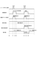
(撮像時における制御部115のタイミングチャート)
図6は、図2に示したカメラ100の撮像時における制御部115が行う処理の進行を示すタイミングチャートである。
(Timing chart of the
FIG. 6 is a timing chart showing the progress of the processing performed by the
図6において、時刻t0からt4の間にスルー画像が表示部111に表示される。また、ピッチ方向振れ検出部120aおよびヨー方向振れ検出部120bは常時、カメラ100の振れを検出している。
In FIG. 6, a through image is displayed on the
次に、時刻t1では、ユーザによるレリーズボタン107の半押し操作(SW1)が検出されることに応じて制御部115による振動デバイス動作処理が開始され、制御部115から振動デバイス109に駆動信号が送られる。
Next, at time t1, in response to detection of a half-press (SW1) of the
この駆動信号に応じて振動デバイス109が時刻t1からt2の期間に振動してユーザに半押し操作した触覚(触感)をフィードバックする。
In response to this drive signal, the
振動デバイス109に駆動信号が送られた直後の時刻t1からt3の期間に、制御部115は、AF、AEおよびAWB処理を実行する。
During the period from time t1 to t3 immediately after a drive signal is sent to the
次に、時刻t2において、ユーザによるレリーズボタン107の全押し操作(SW2)が検出されると、制御部115による振動デバイス動作処理が開始され、制御部115から振動デバイス109に駆動信号が送られる。
Next, at time t2, when a full press (SW2) of the
この駆動信号に応じて振動デバイスが時刻t4からt5の期間に振動してユーザに全押し操作した触覚(触感)をフィードバックする。 In response to this drive signal, the vibration device vibrates during the period from time t4 to t5, providing the user with haptic feedback (feeling) of the full press operation.
振動デバイス109に駆動信号が送られた直後の時刻t4からt6の期間に行う露光処理の説明を行う。
The exposure process performed during the period from time t4 to t6 immediately after a drive signal is sent to the
その期間に、制御部115は、ピッチ方向振れ検出部120aおよびヨー方向振れ検出部120bによって検出された振れ信号に基づいてレンズシフトユニット118とセンサユニット126を駆動して手振れを補正し、撮像部126に露光処理を行わせる。
During that period, the
図6のタイミングチャートにおいて、SW2の検出に応じた振動デバイス109の振動発生期間(t4~t5)は、手振れ補正が行われる振れ信号検出期間と手振れ補正を行いながら露光する期間(t4~t6)と重なっている。
In the timing chart of FIG. 6, the period (t4 to t5) during which vibration is generated by the
つまり、振動デバイス109が駆動されて振動を発生したときに、ピッチ方向振れ検出部120aとヨー方向振れ検出部120bやレンズシフトユニット118とセンサユニット126に影響を与えてしまうと、手振れ補正結果に影響が出る可能性がある。
In other words, when the
このため、レリーズボタン操作時は、他の操作部材操作時と異なり、振動デバイスの振動を小さくし、ピッチ方向振れ検出部120a、ヨー方向振れ検出部120b、レンズシフトユニット118およびセンサユニット126への影響を最小限にする必要がある。
For this reason, when the release button is operated, unlike when other operating members are operated, it is necessary to reduce the vibration of the vibration device and minimize the effect on the pitch direction
図5で説明した通り、レリーズボタン操作時は、振動伝搬部207bはレリーズボタンの当接部106bと接触している。
As explained in FIG. 5, when the release button is operated, the
そのため、振動デバイス109の振動を小さくしても、レリーズボタン106を操作する指に振動による操作感を与えることが可能となる。
Therefore, even if the vibration of the
つまり、レリーズボタン106を操作した際に、振動デバイス109の振動により発生する雑音は最小限に抑えつつ、ユーザに撮影した操作感を与えることを可能としている。
In other words, when the
(カメラ100の振動デバイス管理パターン)
カメラ100の振動デバイス管理パターンについて、図7を参照して説明する。カメラ100に備えられた振動デバイス109は、特定の振動パターンに基づいて制御される。
(Vibration device management pattern of camera 100)
The vibration device management pattern of the
振動パターンは、振動デバイス109を駆動させる際の振動周波数、振動自体の強さを調整できる振幅、触覚(触感)を感じ取れる時間に関する振動持続時間などが振動パターンを決めるパラメータに含まれる。
The parameters that determine the vibration pattern include the vibration frequency when driving the
例えば、カメラ100のレリーズボタン106や操作部114を操作された場合、振動パターンが各撮影設定の状態に関わらず同じパターンである。
For example, when the
その場合、ユーザが求める操作感に対して異なる操作感を与えてしまい、違和感を与えてしまうことが考えられる。 In that case, the user may experience a different operating feel than they are expecting, which may cause discomfort.
そこで、本発明はユーザの各撮影設定に対応した振動パターンに基づいて振動デバイス109を駆動させることができるようにした。
Therefore, the present invention makes it possible to drive the
図7に示すような振動パターン管理テーブル(以降、管理テーブル)に管理データ情報としてカメラ100の記憶部132で記憶され、制御部115はユーザが設定した撮影設定に対応した振動パターンに変更することができる。
The vibration pattern management table (hereinafter, the management table) as shown in FIG. 7 is stored in the
(連写設定と振動デバイス管理テーブルとを関連付けた図)
まず、図7(a)は、本発明の実施形態の一例として、レリーズボタン106操作時の振動デバイス109の動作モードにおいて、静音モードやシャッタ方式、連写設定と振動デバイス管理テーブルとを関連付けた図である。
(A diagram showing the relationship between the continuous shooting setting and the vibration device management table)
First, FIG. 7A is a diagram showing an example of an embodiment of the present invention in which the silent mode, shutter mode, and continuous shooting settings are associated with a vibration device management table in the operation mode of the
ユーザがメカシャッタを選択している場合は、撮影時のメカシャッタの動作による振動や音が発生するため、レリーズボタン106を操作した時に振動デバイス109は特に動作しない。
If the user has selected the mechanical shutter, vibrations and noises will be generated by the operation of the mechanical shutter when taking a picture, so the
つまり、記憶部132は、メカシャッタモードの管理テーブルを記憶されていない。
In other words, the
電子シャッタは、メカシャッタの限界シャッタ速度を上回るシャッタ速度で撮影可能であるため、露出の自由度を高め、高輝度な環境下においても光量を調整するフィルターを使用することなく撮影領域を広げてくれる。 The electronic shutter allows shooting at shutter speeds faster than the limit of mechanical shutters, increasing the freedom of exposure and expanding the shooting range even in high-brightness environments without the need for filters to adjust the amount of light.
しかし、電子シャッタの場合、ユーザはメカシャッタで得られていた撮影した操作感を得ることができない。つまり、ユーザが電子シャッタを選択している場合は、メカシャッタ動作の振動に代わる操作感をユーザに伝達する必要がある。 However, with an electronic shutter, the user cannot get the same feeling of control when taking a picture that they get with a mechanical shutter. In other words, when a user selects an electronic shutter, it is necessary to convey to the user a feeling of control that replaces the vibration of a mechanical shutter operation.
つまり、記憶部132は、電子シャッタモードの管理テーブルT1が管理されている。
In other words, the
管理テーブルT1は、レリーズボタン106に固有の共振周波数付近で振動デバイス109を振動させることで、効率よく振動を発生させ、ユーザに操作感を与えることが可能な振動パターンが管理されている。
Management table T1 manages vibration patterns that can efficiently generate vibrations and provide the user with a sense of operation by vibrating the
また、ユーザが静かな環境下での撮影に適した静音モードを選択している場合は、制御部115は自ずと電子シャッタ静音モードに切り替える。
Also, if the user selects the silent mode, which is suitable for shooting in a quiet environment, the
電子シャッタモードと同様に、撮影した操作感をユーザに伝達するが、振動デバイス109により発生する雑音は最小限にする必要がある。
As with the electronic shutter mode, the feeling of taking a picture is conveyed to the user, but the noise generated by the
つまり、記憶部132は、振動デバイス109の振動により発生する雑音を最小限に抑えた管理パターンT3が管理されている。
In other words, the
例えば、管理パターンT1に対して、共振周波数付近に設定された振動周波数のパラメータはそのままで、振幅のパラメータを小さくしても良いし、共振周波数付近に設定された振動周波数のパラメータを変更し、更に振幅のパラメータも小さくしても良い。 For example, for management pattern T1, the parameters of the vibration frequency set near the resonant frequency may be left unchanged and the parameters of the amplitude may be reduced, or the parameters of the vibration frequency set near the resonant frequency may be changed and the parameters of the amplitude may also be reduced.
さらに、電子シャッタの場合、撮影設定次第で連写枚数が秒間数十枚を超える高速連写が可能である。 In addition, with an electronic shutter, high-speed continuous shooting is possible, exceeding dozens of frames per second, depending on the shooting settings.
高速連写撮影時に、単写撮影時と同じ振動パターンで駆動させると、高速連写撮影の間隔に対して、単写撮影時の振動デバイスの振動継続時間が大きい。 When using the same vibration pattern during high-speed continuous shooting as during single shot shooting, the duration of vibration of the vibration device during single shot shooting is longer than the interval between high-speed continuous shot shooting.
そのため、徐々に撮影と振動のタイミングが合わなくなりユーザに違和感ある操作感を与えてしまう可能性がある。 As a result, the timing of the capture and vibration may gradually become out of sync, giving the user an uncomfortable feeling when operating the device.
つまり、記憶部132は、単写撮影時の管理テーブルT1やT3に対して少なくとも振動継続時間を小さくし、高速連写撮影の間隔に対応した管理テーブルT2やT4が管理されている。
In other words, the
カメラ100に搭載された振動デバイス109の応答速度上、振動継続時間を小さくする変更が対応できない場合は、さらに振幅のパラメータを変更することで高速連写撮影の間隔に対応しても良い。
If the response speed of the
(管理テーブルT1)
図7(b)は、前述した4種類の管理テーブルの内、管理テーブルT1とT2を例として示した図である。
(Management Table T1)
FIG. 7B is a diagram showing management tables T1 and T2 as examples of the four types of management tables mentioned above.
図7(b)で示す通り、管理テーブルは各シャッタ速度に対応した振動パターンが管理されている。 As shown in Figure 7 (b), the management table manages vibration patterns corresponding to each shutter speed.
各振動パターンのパラメータの詳細は記載しないが、振動デバイス109を駆動するための振動周波数、振幅、振動継続時間等を組み合わせた振動の合成波形が管理されている。
The parameters of each vibration pattern will not be described in detail, but a composite vibration waveform that combines vibration frequency, amplitude, vibration duration, etc. to drive the
図7(b)に示すT1-15の振動パラメータは、シャッタ速度の遅いT1-10の振動パラメータに対して、少なくとも振動継続時間のパラメータを小さいものに変更している。 The vibration parameters of T1-15 shown in FIG. 7(b) are changed to a smaller value for at least the vibration duration parameter compared to the vibration parameters of T1-10, which has a slow shutter speed.
この変更により、メカシャッタで得られていたシャッタ速度を早くしたことを認知させる操作感を与えることが可能である。 This change makes it possible to give the user a feeling of awareness that the shutter speed has been increased compared to what was achieved with a mechanical shutter.
連写設定がONに設定されると、撮影時のシャッタ速度が速くなるにつれ、連写撮影枚数が多くなる。 When the continuous shooting setting is set to ON, the faster the shutter speed when shooting, the more continuous shots will be taken.
つまり、記憶部132は、シャッタ速度に応じた連写撮影の間隔に対応可能な管理パターンT2が管理されている。
In other words, the
例えば、図7(b)に示すT2-15は、連写設定がOFFに設定されたT1-15に対して、少なくとも振動継続時間のパラメータを小さいものに変更している。この変更により、電子シャッタの高速連写撮影の間隔にあった操作感を与えることが可能となる。 For example, in T2-15 shown in FIG. 7(b), at least the vibration duration parameter has been changed to a smaller value compared to T1-15, which has the continuous shooting setting set to OFF. This change makes it possible to provide an operational feel that matches the intervals between high-speed continuous shooting with the electronic shutter.
カメラ100に搭載された振動デバイス109の応答速度次第で、振動継続時間を小さくする変更が対応できない場合は、さらに振幅のパラメータを変更することで高速連写撮影の間隔に対応しても良い。
If the response speed of the
図7(b)に示すT1-10のように撮影時のシャッタ速度が遅く連写撮影の間隔が、T1-10の振動継続時間より大きくなる場合、連写設定がONであっても連写設定OFFの振動パターンと同じものを格納して良い。 When the shutter speed during shooting is slow and the interval between continuous shots is longer than the vibration duration of T1-10, as in T1-10 shown in Figure 7(b), the same vibration pattern as when the continuous shooting setting is OFF may be stored even if the continuous shooting setting is ON.
(T2やT4の振動パターン)
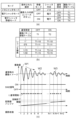
図7(c)は、連写撮影に対応した管理テーブルT2やT4の振動パターンにおいて、高速連写時の撮影間隔に対して、単写撮影時の振動デバイスの振動継続時間が大きい場合の振動イメージを示した図である。
(T2 and T4 vibration patterns)
FIG. 7C is a diagram showing an image of vibration when the vibration duration of the vibration device during single shot shooting is longer than the shooting interval during high-speed continuous shooting in the vibration patterns of management tables T2 and T4 corresponding to continuous shooting.
制御部115はSW2信号がONになったことを検出すると、制御部115は管理パターンを参照して、シャッタ速度に対応した振動パターンで振動デバイス109を駆動する。
When the
制御部115がSW2信号を検出して1枚目の撮影時は、単写撮影時と同じ振動パターンW1で振動デバイスを駆動させる。
When the
その後も制御部115がSW2信号を検出し続けた場合、2枚目、3枚目と徐々に振動デバイスから発生する振幅を小さくし振動収束時間を短くすることで、高速連写時の撮影間隔に対応可能な振動パターンW2にする。
If the
ここで、振動パターンW1から振動パターンW2へ急激に変化させてしまうと、ユーザは振動の大幅な変化を違和感として感じてしまう恐れがある。 If the vibration pattern suddenly changes from W1 to W2, the user may feel uncomfortable with the large change in vibration.
そのため、記憶部132は、連写撮影に対応した図7(c)のような振動パターンW1からW2へ徐々に減衰させる振動パターンが記憶されている。
For this reason, the
その後は、振動デバイス109は連写撮影の間隔に対応可能な振動パターンW2で一定の振動で駆動し、ユーザに撮影が継続していることを認知させる操作感を与える。
After that, the
また、連写撮影を長時間続けた場合、撮影した情報を記憶する記憶部132のバッファやSDカードなどの記録メディアの容量が足りなくなり、連写撮影は強制的に終了することになることがある。
In addition, if continuous shooting continues for a long period of time, the capacity of the buffer of the
ユーザは自分の意図しないときに連写撮影が強制的に終了するため、大事な撮影シーンを撮り逃してしまう可能性がある。 The user may miss an important shot because the continuous shooting mode is forcibly terminated at an unintended time.
そこで、連写撮影中に、記憶部のバッファがある閾値に達したところで、振動パターンW2とは異なる振動パターンW3で駆動させても良い。 Therefore, when the buffer of the memory unit reaches a certain threshold during continuous shooting, the camera may be driven with vibration pattern W3, which is different from vibration pattern W2.
または、一定の撮影枚数N枚目や一定の撮影枚数毎に、振動パターンW2とは異なる振動パターンW3で振動デバイスを駆動させても良い。 Alternatively, the vibration device may be driven with vibration pattern W3, which is different from vibration pattern W2, after a certain number of shots N or after every certain number of shots.
このことにより、連写撮影が強制的に終了する事前にユーザに知らせたり、連写撮影の枚数がどれ位に達したかをユーザに知らせることができる。 This allows the user to be notified before continuous shooting is forcibly terminated, and to be informed of the number of continuous shots that have been taken.
上記のように管理テーブルT1乃至T4に振動パターンが記憶されていることで、各撮影設定に対応した振動パターンで振動デバイス109を振動させることができる。
By storing vibration patterns in management tables T1 to T4 as described above, it is possible to vibrate the
(図8~図13に示すフローチャート)
以上説明した振動デバイス109の振動制御について、図8~図13に示すフローチャートを参照して、説明を行う。
(Flowcharts shown in FIGS. 8 to 13)
The vibration control of the
まず、カメラ100の電源レバー104や再生ボタン1101を操作すると、制御部115は、ステップS101にて、起動方法を調べる。
First, when the
この結果、再生ボタン1101で起動していればステップS102へ進み、再生モード処理を実行し、電源レバー104で起動していればステップS103へ進む。
If the device was started using the
次のステップS103では、制御部115は、操作部114の入力を監視し、撮影動作を開始しない操作部入力では、ステップS104へ進み、操作入力処理を実行する。
In the next step S103, the
一方、撮影動作を開始するレリーズボタン106や動画ボタン1102が操作されると、ステップS105へ進み、撮影開始処理が実行される。
On the other hand, when the
これらの再生モード、操作入力処理および撮影開始処理の詳細は、図9乃至図10を用いて後述する。 Details of these playback modes, operation input processing, and shooting start processing will be described later using Figures 9 and 10.
ステップS105での撮影開始処理のルーチンが終了すると、次のステップS106へ進み、制御部115は電源の状態を判定する。
When the routine for starting shooting in step S105 is completed, the process proceeds to the next step S106, where the
そして、電源がオフされていなければステップS101へ戻り、電源がオフされていれば、制御部115はシステム終了の処理を行う。
If the power is not turned off, the process returns to step S101, and if the power is turned off, the
(ステップS102における再生モード処理)
次に、図9のフローチャートを用いて、図8のステップS102における再生モード処理について説明する。
(Playback Mode Processing in Step S102)
Next, the playback mode process in step S102 in FIG. 8 will be described with reference to the flowchart in FIG.
まず、ステップS201でSDカードなどの記録メディアに格納された撮影画像を表示し、次のステップS202で制御部115は操作部114の入力を監視する。
First, in step S201, a captured image stored in a recording medium such as an SD card is displayed, and in the next step S202, the
ステップS202にて撮影動作を開始する操作部が操作されると、次のステップS203へ進み、撮像した画像データを逐次表示するスルー表示状態に設定してこの再生モード処理のルーチンを終了する。 When the operation unit is operated to start the shooting operation in step S202, the process proceeds to the next step S203, where the camera is set to a through-display state in which the captured image data is displayed sequentially, and the playback mode processing routine ends.
ステップS202にて撮影動作を開始しない操作部が操作されると、ステップS204へ進み、入力操作処理が実行される。 If an operation unit that does not start a shooting operation is operated in step S202, the process proceeds to step S204, where input operation processing is executed.
ステップS204での入力操作処理のルーチンが終了すると、ステップS202へ戻り、次の操作部の入力に備える。 When the input operation processing routine in step S204 is completed, the process returns to step S202 to prepare for the next operation input.
(ステップS104における操作入力処理)
次に、図10のフローチャートを用いて、図8のステップS104における操作入力処理について説明する。
(Operation Input Processing in Step S104)
Next, the operation input process in step S104 in FIG. 8 will be described with reference to the flowchart in FIG.
まず、ステップS301にて、制御部115は振動デバイス109の静音モード設定状態を調べ、静音モードがONに設定されていたならば、ステップS302へ進んで、振動デバイスの動作モードを静音モードに設定する。
First, in step S301, the
一方、静音モードがOFFに設定されていたならば、ステップS303へ進み、振動デバイスの動作モードを通常モードに設定する。 On the other hand, if the silent mode is set to OFF, proceed to step S303 and set the operating mode of the vibration device to normal mode.
なお、振動デバイス109の動作モードの設定は、制御部115の内部メモリ或いは記憶部132に記憶する。
The operating mode setting of the
次のステップS304にて、制御部115は、前のステップS302あるいはS303で設定された振動デバイスの動作モードに基づいて、振動デバイス109を駆動するように指令する。
In the next step S304, the
これにより、制御部115は、振動デバイス駆動部134を制御して、振動デバイス109を振動させ、ユーザに操作部を入力した操作感をフィードバックする。
As a result, the
次のステップS305にて、制御部115はカメラ100の電源状態を判定し、電源がOFFされていれば、制御部115はシステム終了の処理を行い、電源がONされていれば、この再生モード処理のルーチンを終了する。
In the next step S305, the
(ステップS105における撮影開始処理)
次に、図11のフローチャートを用いて、図8のステップS105における撮影開始処理について説明する。
(Shooting start process in step S105)
Next, the shooting start process in step S105 in FIG. 8 will be described with reference to the flowchart in FIG.
まず、ステップS401にて、制御部115は撮影モードを調べる。この結果、動画撮影であればステップS402へ進み、動画モード処理を実行し、静止画撮影であればステップS403へ進む。
First, in step S401, the
次のステップS403では、制御部115はシャッタの動作モードを調べ、電子シャッタモードがONに設定されていたならば、ステップS404へ進み、振動デバイスの動作モード状態を調べる。
In the next step S403, the
静音モードがONに設定されていたならば、ステップS405へ進み、電子シャッタ静音モード処理を実行し、静音モードがOFFに設定されていたならば、ステップS406へ進み、カメラ100に取り付けられているレンズ102を確認する。
If silent mode is set to ON, proceed to step S405 and execute electronic shutter silent mode processing; if silent mode is set to OFF, proceed to step S406 and check the
例えば、望遠レンズやマクロレンズなどの手振れに対して敏感度の高いレンズであれば、S405へ進む。 For example, if the lens is highly sensitive to camera shake, such as a telephoto lens or macro lens, proceed to S405.
ステップS406で、例えばズームレンズなどの手ブレに対して敏感度の高い領域と低い領域を持つレンズの場合は、次のステップS407へ進み、ユーザが設定している撮像光学系の焦点距離と、その焦点距離における敏感度を確認する。 In step S406, if the lens has areas of high and low sensitivity to camera shake, such as a zoom lens, the process proceeds to the next step S407, where the focal length of the imaging optical system set by the user and the sensitivity at that focal length are confirmed.
敏感度が所定の値よりも高い場合は、ステップ405へ進み、低い場合はステップS408へ進み、電子シャッタモード処理を実行する。 If the sensitivity is higher than the predetermined value, proceed to step S405; if it is lower, proceed to step S408 and execute electronic shutter mode processing.
一方、ステップS403で、電子シャッタモードがOFFに設定されていたならば、ステップS407へ進む。 On the other hand, if the electronic shutter mode is set to OFF in step S403, proceed to step S407.
そして、制御部115は、モードダイアル105が特定の撮影モード(以下プラスムービーオートモードと呼ぶ)に設定されているかどうかを調べる。
Then, the
ここで、プラスムービーオートモードは、静止画撮影した時に、静止画の記録を行うとともに、静止画撮影前の所定秒数の動画を同時に記録するため、撮影時に発生する動作音は小さくすることが望まれている。 In Plus Movie Auto mode, when a still image is shot, the camera records the still image and simultaneously records a certain number of seconds of video before the still image is shot, so it is desirable to keep the operating noise generated during shooting to a minimum.
それ故に、プラスムービーオートモードに設定されていたならば、ステップS405へ進み、電子シャッタ静音モード処理を実行する。 Therefore, if the Plus Movie Auto mode is set, proceed to step S405 and execute electronic shutter silent mode processing.
そして、プラスムービーオートモードの他のモードに設定されていたならば、ステップS408へ進み、メカシャッタモード処理を実行する。このように、撮影モードやシャッタモードの設定状態を監視することで、適切な振動デバイスの動作モードを選択可能にしている。 If the mode is set to a mode other than Plus Movie Auto mode, the process proceeds to step S408 and executes mechanical shutter mode processing. In this way, by monitoring the setting status of the shooting mode and shutter mode, it is possible to select an appropriate operating mode for the vibration device.
次に、図12~図14のフローチャートを用いて、図11の振動デバイスの各動作モードにおける処理について説明する。 Next, the processing in each operation mode of the vibration device in FIG. 11 will be explained using the flowcharts in FIG. 12 to FIG. 14.
(動画モードにおける処理)
図12のフローチャートを用いて、動画モードにおける処理について説明する。
(Processing in Movie Mode)
The process in the moving image mode will be described with reference to the flowchart in FIG.
まず、ステップS501にて、制御部115はレリーズボタン106が押されてレリーズSW1がONされていたならば、次のステップS502へ進む。
First, in step S501, if the
動画ボタン1101が押されて動画SWがONされていたならば、ステップS503へ進む。ステップS502では、制御部115は操作部の入力を監視し、レリーズSW2がONされていればステップS503へ進み、振動デバイスの動作モードを静音モードに設定する。
If the
一方、レリーズSW2が一定時間以上OFFの状態が続けば、ステップS504に進み、レリーズSW1の状態を監視する。 On the other hand, if release SW2 remains OFF for a certain period of time or longer, proceed to step S504 and monitor the state of release SW1.
レリーズSW1がONの状態であれば、ステップS502へ戻り、レリーズSW1がOFFの状態であれば、この動画モード処理のルーチンを終了する。 If release SW1 is ON, return to step S502; if release SW1 is OFF, end this video mode processing routine.
ステップS505では、設定された振動デバイスの動作モードに基づいて、振動デバイスを動作するように指令する。 In step S505, a command is issued to operate the vibration device based on the set vibration device operation mode.
次のステップS506では、引き続き操作部の入力を監視し、撮影を停止する操作部の入力でない場合は、ステップS507にて、静音モードで振動デバイスを動作するように指令し、ステップS506に戻る。 In the next step S506, the input from the operation unit continues to be monitored, and if the input from the operation unit is not an input to stop image capture, in step S507, a command is issued to operate the vibration device in silent mode, and the process returns to step S506.
ステップS506で、撮影を停止する操作部の入力である場合は、この動画モード処理のルーチンを終了する。 In step S506, if the input from the operation unit is to stop recording, the video mode processing routine is terminated.
このように、動画撮影中では、振動デバイスは常に静音モードで動作し、振動デバイスの駆動音を少なくしつつ、ユーザに操作部を操作した操作感を与えることができる。 In this way, during video capture, the vibration device always operates in silent mode, reducing the drive noise of the vibration device while still giving the user the feeling of operating the operation unit.
(電子シャッタモードと電子シャッタ静音モードにおける処理)
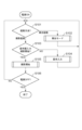
図13のフローチャートを用いて、電子シャッタモードと電子シャッタ静音モードにおける処理について説明する。
(Processing in electronic shutter mode and silent electronic shutter mode)
The processing in the electronic shutter mode and silent electronic shutter mode will be described with reference to the flowchart in FIG.
電子シャッタモードと電子シャッタ静音モードは、後述するステップS605とS607の振動デバイスの動作モード(振動モード)の設定値が異なるだけである。 The only difference between the electronic shutter mode and silent electronic shutter mode is the setting value of the vibration device operation mode (vibration mode) in steps S605 and S607 described below.
まず、ステップS601にて、制御部115はレリーズSW2の状態を監視し、レリーズSW2がONであれば、ステップS602に進む。
First, in step S601, the
レリーズSW2がONされていなければ、ステップS603でレリーズSW1の状態を監視する。 If release SW2 is not ON, the state of release SW1 is monitored in step S603.
ステップS603で、レリーズSW1がONであれば、ステップS601に戻り、レリーズSW1がOFFであれば、この電子シャッタモード処理のルーチンを終了する。 In step S603, if release SW1 is ON, the process returns to step S601, and if release SW1 is OFF, the electronic shutter mode processing routine ends.
次に、ステップS602で制御部115は撮影するシャッタ速度を確認し、ステップS604で制御部115は、連写撮影の設定を確認する。
Next, in step S602, the
連写撮影の設定がOFF(単写撮影)であれば、ステップS605に進み、振動デバイスの動作モードを電子シャッタの単写モードに設定する。 If the continuous shooting setting is OFF (single shooting), proceed to step S605 and set the operating mode of the vibration device to the electronic shutter single shooting mode.
つまり、制御部115は、次のステップS606にて、図6に示す管理テーブルT1に基づいて、シャッタ速度に応じた振動パターンを参照して、振動デバイスに指令を行う。
In other words, in the next step S606, the
これにより、電子シャッタによる静止画撮影中においても、振動デバイスを駆動させ、メカシャッタが動作したような操作感をユーザに与える。 This allows the vibration device to be activated even while capturing still images using the electronic shutter, giving the user the sensation of using a mechanical shutter.
一方、ステップS604で連写撮影の設定がONであれば、ステップS607に進み、振動デバイスの動作モード(振動モード)を電子シャッタの連写モードに設定する。 On the other hand, if the continuous shooting setting is ON in step S604, the process proceeds to step S607, where the operation mode (vibration mode) of the vibration device is set to the electronic shutter continuous shooting mode.
次のステップS608にて、図6に示す管理テーブルT2に基づいて、シャッタ速度に応じた振動パターンを参照して、振動デバイスに指令を行う。 In the next step S608, a command is issued to the vibration device by referencing the vibration pattern corresponding to the shutter speed based on the management table T2 shown in FIG. 6.
その後、ステップS609でレリーズSW2の状態を監視し続ける。 Then, in step S609, the state of release SW2 continues to be monitored.
S609でレリーズSW2がONの状態が続けば、ステップS608の振動デバイスの動作を継続して、連写撮影している間、ユーザに撮影した操作感を与え続けることができる。 If release SW2 remains ON in S609, the operation of the vibration device in step S608 continues, allowing the user to continue to feel as if they are taking pictures while continuous shooting is being performed.
ステップS609でレリーズSW2がOFFになれば、この電子シャッタモードの処理のルーチンを終了する。 If release SW2 is turned OFF in step S609, the electronic shutter mode processing routine ends.
ここで、電子シャッタ静音モードの場合は、前述したステップS605、S607の振動デバイスの動作モードの設定値が電子シャッタ静音モード用の値になる。 Here, in the case of electronic shutter silent mode, the setting values of the vibration device operation mode in steps S605 and S607 described above will be the values for electronic shutter silent mode.
(メカシャッタモードにおける処理)
図14のフローチャートを用いて、メカシャッタモードにおける処理について説明する。
(Processing in mechanical shutter mode)
The process in the mechanical shutter mode will be described with reference to the flow chart of FIG.
まず、ステップS701にて、制御部115はレリーズSW2の状態を監視し、レリーズSW2がONであれば、ステップS702に進み、レリーズSW2がOFFであれば、ステップS703でレリーズSW1の状態を監視する。
First, in step S701, the
ステップS703で、レリーズSW1がONであれば、ステップS701に戻り、レリーズSW1がOFFであれば、このメカシャッタモードの処理のルーチンを終了する。 In step S703, if release SW1 is ON, the process returns to step S701, and if release SW1 is OFF, the mechanical shutter mode processing routine ends.
次に、ステップS702でレリーズSW1の状態を監視し、レリーズSW1がONであれば、ステップS701に戻り、レリーズSW1がOFFであれば、このメカシャッタモード処理のルーチンを終了する。 Next, in step S702, the state of release SW1 is monitored, and if release SW1 is ON, the process returns to step S701, and if release SW1 is OFF, the mechanical shutter mode processing routine is terminated.
このように、メカシャッタモードにおいては、撮影した際にはメカシャッタ動作による振動や音によりユーザに撮影した操作感を与えることができる為、振動デバイスを駆動する必要はない。 In this way, in mechanical shutter mode, the vibration and sound produced by the mechanical shutter operation can give the user the feeling of taking a picture, so there is no need to activate the vibration device.
本実施例の撮像装置は、撮影の露光開始と露光終了を指示する撮影開始操作手段105、106、110と、撮影開始操作手段に対するユーザーの操作に応じた触覚(触感)をユーザーに伝えるために撮像装置を振動させる振動デバイス109とを有する。
The imaging device of this embodiment has shooting start operation means 105, 106, and 110 that instruct the start and end of exposure for shooting, and a
また、振動デバイスの駆動を制御する複数の振動パターンを有する振動制御手段134と、を有する。 It also has vibration control means 134 that has multiple vibration patterns that control the driving of the vibration device.
振動制御手段134は、撮影記録の期間中、撮影モード及び撮影開始操作手段105、106、110に対するユーザーの操作に応じて振動デバイス109の振動パラメータを変更する。
During the shooting and recording period, the vibration control means 134 changes the vibration parameters of the
振動デバイスの振動パラメータは、振動周波数、振幅、振動継続時間を含んでいる。 Vibration parameters of a vibration device include vibration frequency, amplitude, and vibration duration.
振動デバイスが取り付けられた外装部材201と、振動デバイスに接触している振動伝搬部材207と、撮影開始操作手段106が第一の位置から第二の位置に操作されたことを検出する検出手段205とを有する。
It has an
振動デバイスは、第二の位置の撮影開始状態において撮像開始操作手段を振動させる第1の振動モードと、記第一の位置において前記外装部材を振動させる第2の振動モードを有する。 The vibration device has a first vibration mode that vibrates the imaging start operation means in the imaging start state in the second position, and a second vibration mode that vibrates the exterior member in the first position.
第一の位置において撮影開始操作手段が振動伝搬部材と接触せず、第二の位置又は撮影開始操作手段が第二の位置に達する前において撮影開始操作手段が振動伝搬部材に接触する。 At the first position, the shooting start operating means does not come into contact with the vibration transmission member, and at the second position or before the shooting start operating means reaches the second position, the shooting start operating means comes into contact with the vibration transmission member.
撮影モードは、メカシャッタモードと電子シャッタモードとを有する。 Shooting modes include mechanical shutter mode and electronic shutter mode.
振動制御手段は、メカシャッタモードである場合、振動デバイスの駆動をOFFに設定し、電子シャッタモードである場合、振動デバイスの駆動をONに設定する。 The vibration control means sets the vibration device to OFF when in mechanical shutter mode, and sets the vibration device to ON when in electronic shutter mode.
振動制御手段は、静音モードである場合、振動デバイスの振動を小さく設定し、非静音モードである場合、振動デバイスの振動を大きく設定する。 The vibration control means sets the vibration of the vibration device to low when in silent mode, and sets the vibration of the vibration device to high when in non-silent mode.
電子シャッタモードは、振動デバイスの静音モードと振動デバイスの非静音モードとを有する。 The electronic shutter modes include a silent mode for the vibration device and a non-silent mode for the vibration device.
振動制御手段は、静音モードである場合、振動デバイスの振動を小さく設定し、非静音モードである場合、振動デバイスの振動を大きく設定する。 The vibration control means sets the vibration of the vibration device to low when in silent mode, and sets the vibration of the vibration device to high when in non-silent mode.
振動制御手段は、電子シャッタのシャッタ速度が速いとき電子シャッタのシャッタ速度が遅いときに比べて、振動デバイスの振動継続時間を短く設定する。 The vibration control means sets the vibration duration of the vibration device to be shorter when the electronic shutter has a fast shutter speed than when the electronic shutter has a slow shutter speed.
振動制御手段は、電子シャッタのシャッタ速度が速いとき電子シャッタのシャッタ速度が遅いときに比べて、振動デバイスの振幅を小さく設定しても良い。 The vibration control means may set the amplitude of the vibration device to be smaller when the electronic shutter has a fast shutter speed than when the electronic shutter has a slow shutter speed.
振動制御手段は、電子シャッタの連写する撮影の枚数が多いとき電子シャッタの連写する撮影の枚数が少ないときに比べて、振動デバイスの振動継続時間を短く設定する。 The vibration control means sets the vibration duration of the vibration device to be shorter when the number of images captured continuously by the electronic shutter is large than when the number of images captured continuously by the electronic shutter is small.
振動制御手段は、電子シャッタの連写する撮影の枚数が多いとき電子シャッタの連写する撮影の枚数が少ないときに比べて、振動デバイスの振幅を小さく設定しても良い。 The vibration control means may set the amplitude of the vibration device to be smaller when the number of images captured continuously by the electronic shutter is large than when the number of images captured continuously by the electronic shutter is small.
振動制御手段は、1秒間の撮影の枚数の速度が所定の閾値以上に設定されている場合の振動デバイスの振幅が1秒間の撮影の枚数の速度が所定の閾値未満に設定されている場合の振動デバイスの振幅よりも小さく設定する。 The vibration control means sets the amplitude of the vibration device when the rate of the number of shots taken per second is set to a predetermined threshold or higher to be smaller than the amplitude of the vibration device when the rate of the number of shots taken per second is set to be less than the predetermined threshold.
撮像光学系の焦点距離が長いときの振動デバイスの振動が撮像光学系の焦点距離が短いときの振動デバイスの振動よりも小さい。 The vibration of the vibration device when the focal length of the imaging optical system is long is smaller than the vibration of the vibration device when the focal length of the imaging optical system is short.
上述のように、撮影設定に応じて適切に振動デバイスの振動制御を行うことで、振動デバイスの駆動が騒音になることなく、ユーザに違和感ない操作感を与えることができる撮像装置を提供することが可能となる。以上説明した各実施例は代表的な例にすぎず、本発明の実施に際しては、各実施例に対して種々の変形や変更が可能である。 As described above, by appropriately controlling the vibration of the vibration device according to the shooting settings, it is possible to provide an imaging device that can give the user a natural operating feel without the drive of the vibration device becoming noisy. The embodiments described above are merely representative examples, and various modifications and variations are possible when implementing the present invention.
106 レリーズボタン
109 振動デバイス
134 振動デバイス駆動部
106
Claims (8)
レリーズボタンと、前記レリーズボタンに対するユーザーの操作に応じた触覚をユーザーに伝えるために前記撮像装置を振動させる振動デバイスと、前記振動デバイスの駆動を制御する複数の振動パターンを有する振動制御手段と、を備え、
前記振動制御手段は、撮影モードが電子シャッタを用いた撮影を行うモードである場合において、連写する撮影の枚数が多いときは連写する撮影の枚数が少ないときに比べて、前記振動デバイスの振動継続時間を短く設定することを特徴とする撮像装置。 In an imaging device that can be switched between a plurality of imaging modes,
a release button; a vibration device that vibrates the imaging device to convey a tactile sensation to a user in response to the user's operation of the release button; and vibration control means having a plurality of vibration patterns that controls the driving of the vibration device,
The imaging device is characterized in that, when the shooting mode is a mode in which shooting is performed using an electronic shutter, the vibration control means sets the vibration duration of the vibration device to be shorter when the number of consecutive shots is large compared to when the number of consecutive shots is small.
前記振動デバイスは、前記第二の位置の撮影開始状態において前記レリーズボタンを振動させる第1の振動モードと、前記第一の位置において前記外装部材を振動させる第2の振動モードを備え、
前記第一の位置において前記レリーズボタンが前記振動伝搬部材と接触せず、前記第二の位置又は前記レリーズボタンが前記第二の位置に達する前において前記レリーズボタンが前記振動伝搬部材に接触することを特徴とする請求項1又は2に記載の撮像装置。 a vibration transmitting member in contact with the vibration device; and a detection means for detecting that the release button has been operated from a first position to a second position,
the vibration device has a first vibration mode for vibrating the release button in a shooting start state at the second position, and a second vibration mode for vibrating the exterior member at the first position;
3. An imaging device as described in claim 1 or 2, characterized in that the release button does not contact the vibration propagation member at the first position, and the release button contacts the vibration propagation member at the second position or before the release button reaches the second position.
前記振動制御手段は、前記静音モードである場合、前記振動デバイスの振動を小さく設定し、前記非静音モードである場合、前記振動デバイスの振動を大きく設定することを特徴とする請求項4に記載の撮像装置。 the mode for photographing using the electronic shutter includes a silent mode of the vibration device and a non-silent mode of the vibration device;
5. The imaging device according to claim 4, wherein the vibration control means sets the vibration of the vibration device to be small when in the silent mode, and sets the vibration of the vibration device to be large when in the non-silent mode.
Priority Applications (2)
| Application Number | Priority Date | Filing Date | Title |
|---|---|---|---|
| JP2020032453A JP7588960B2 (en) | 2020-02-27 | 2020-02-27 | Imaging device |
| US17/180,482 US11687158B2 (en) | 2020-02-27 | 2021-02-19 | Imaging apparatus including a vibration device to provide touch sense to the user based on imaging mode |
Applications Claiming Priority (1)
| Application Number | Priority Date | Filing Date | Title |
|---|---|---|---|
| JP2020032453A JP7588960B2 (en) | 2020-02-27 | 2020-02-27 | Imaging device |
Publications (2)
| Publication Number | Publication Date |
|---|---|
| JP2021136615A JP2021136615A (en) | 2021-09-13 |
| JP7588960B2 true JP7588960B2 (en) | 2024-11-25 |
Family
ID=77463627
Family Applications (1)
| Application Number | Title | Priority Date | Filing Date |
|---|---|---|---|
| JP2020032453A Active JP7588960B2 (en) | 2020-02-27 | 2020-02-27 | Imaging device |
Country Status (2)
| Country | Link |
|---|---|
| US (1) | US11687158B2 (en) |
| JP (1) | JP7588960B2 (en) |
Families Citing this family (18)
| Publication number | Priority date | Publication date | Assignee | Title |
|---|---|---|---|---|
| JP1638776S (en) * | 2018-05-15 | 2019-08-13 | ||
| JP1638779S (en) * | 2018-05-15 | 2019-08-13 | ||
| JP1629825S (en) * | 2018-05-15 | 2019-04-22 | ||
| JP1637187S (en) * | 2018-05-15 | 2019-07-22 | ||
| JP1638777S (en) * | 2018-05-15 | 2019-08-13 | ||
| JP1629824S (en) * | 2018-05-15 | 2019-04-22 | ||
| JP1633586S (en) * | 2018-05-15 | 2019-06-10 | ||
| JP1629820S (en) * | 2018-05-15 | 2019-04-22 | ||
| JP1636781S (en) * | 2018-05-15 | 2019-07-22 | ||
| JP1638780S (en) * | 2018-05-15 | 2019-08-13 | ||
| JP1629828S (en) * | 2018-05-15 | 2019-04-22 | ||
| JP1636779S (en) * | 2018-05-15 | 2019-07-22 | ||
| JP7410623B2 (en) * | 2020-02-27 | 2024-01-10 | キヤノン株式会社 | Electronics |
| JP7438848B2 (en) * | 2020-05-15 | 2024-02-27 | キヤノン株式会社 | Imaging device |
| JP2023104706A (en) * | 2022-01-18 | 2023-07-28 | キヤノン株式会社 | VIBRATION DEVICE, IMAGING DEVICE, CONTROL METHOD OF VIBRATION DEVICE, AND PROGRAM |
| JP2023150183A (en) * | 2022-03-31 | 2023-10-16 | ソニーグループ株式会社 | Imaging device |
| JP2023154673A (en) * | 2022-04-07 | 2023-10-20 | キヤノン株式会社 | Imaging apparatus and control method for the same |
| JP2024179407A (en) * | 2023-06-15 | 2024-12-26 | キヤノン株式会社 | Imaging device and control method thereof |
Citations (7)
| Publication number | Priority date | Publication date | Assignee | Title |
|---|---|---|---|---|
| JP2005173038A (en) | 2003-12-09 | 2005-06-30 | Sony Corp | camera |
| JP2005352927A (en) | 2004-06-14 | 2005-12-22 | Sony Corp | Input device and electronic device |
| JP2006243091A (en) | 2005-03-01 | 2006-09-14 | Alps Electric Co Ltd | Camera |
| JP2012237870A (en) | 2011-05-11 | 2012-12-06 | Olympus Imaging Corp | Drive control device |
| WO2018135313A1 (en) | 2017-01-20 | 2018-07-26 | ソニー株式会社 | Imaging device, imaging method, and program |
| JP2019185023A (en) | 2018-04-03 | 2019-10-24 | キヤノン株式会社 | Electronic device, and control method and program for electronic device |
| JP2020005250A (en) | 2018-06-25 | 2020-01-09 | キヤノン株式会社 | Imaging apparatus having vibration device |
Family Cites Families (4)
| Publication number | Priority date | Publication date | Assignee | Title |
|---|---|---|---|---|
| JP4892829B2 (en) | 2004-11-15 | 2012-03-07 | ソニー株式会社 | Vibration generator, input / output device with tactile function, and electronic device thereof |
| JPWO2012081182A1 (en) * | 2010-12-13 | 2014-05-22 | パナソニック株式会社 | Electronics |
| WO2012176441A1 (en) * | 2011-06-23 | 2012-12-27 | 株式会社ニコン | Imaging device |
| JP7331697B2 (en) * | 2017-10-30 | 2023-08-23 | ソニーグループ株式会社 | Vibration generator, vibration control method and program |
-
2020
- 2020-02-27 JP JP2020032453A patent/JP7588960B2/en active Active
-
2021
- 2021-02-19 US US17/180,482 patent/US11687158B2/en active Active
Patent Citations (7)
| Publication number | Priority date | Publication date | Assignee | Title |
|---|---|---|---|---|
| JP2005173038A (en) | 2003-12-09 | 2005-06-30 | Sony Corp | camera |
| JP2005352927A (en) | 2004-06-14 | 2005-12-22 | Sony Corp | Input device and electronic device |
| JP2006243091A (en) | 2005-03-01 | 2006-09-14 | Alps Electric Co Ltd | Camera |
| JP2012237870A (en) | 2011-05-11 | 2012-12-06 | Olympus Imaging Corp | Drive control device |
| WO2018135313A1 (en) | 2017-01-20 | 2018-07-26 | ソニー株式会社 | Imaging device, imaging method, and program |
| JP2019185023A (en) | 2018-04-03 | 2019-10-24 | キヤノン株式会社 | Electronic device, and control method and program for electronic device |
| JP2020005250A (en) | 2018-06-25 | 2020-01-09 | キヤノン株式会社 | Imaging apparatus having vibration device |
Also Published As
| Publication number | Publication date |
|---|---|
| JP2021136615A (en) | 2021-09-13 |
| US20210271325A1 (en) | 2021-09-02 |
| US11687158B2 (en) | 2023-06-27 |
Similar Documents
| Publication | Publication Date | Title |
|---|---|---|
| JP7588960B2 (en) | Imaging device | |
| US11442340B2 (en) | Electronic apparatus, electronic apparatus control method and storage medium | |
| JP2011160067A (en) | Camera shake correcting device and method, camera module, and cellular phone | |
| JP2006074652A (en) | Imaging apparatus | |
| JP2011158551A (en) | Camera module and cellular phone | |
| US11415862B2 (en) | Electronic apparatus | |
| CN110636189B (en) | Image pickup apparatus having vibration device | |
| US11218619B2 (en) | Image capturing apparatus, method for the same, and storage medium where while an image sensor is located in an area an optical member and a vibration transmission member are not in contact with each other | |
| US11539886B2 (en) | Camera with shutter release control of frame rate | |
| US11500466B2 (en) | Image pickup apparatus with vibration device | |
| US11297235B2 (en) | Optical apparatus having vibration device | |
| JP7676247B2 (en) | optical equipment | |
| JP7247009B2 (en) | Imaging device with vibration device | |
| JP7187230B2 (en) | Electronic equipment with vibration device | |
| JP7746342B2 (en) | Optical control device, optical device and control method thereof | |
| US20260006325A1 (en) | Electronic apparatus | |
| JP7309432B2 (en) | Optical instrument with vibration device | |
| WO2019194037A1 (en) | Electronic apparatus, electronic apparatus control method and program | |
| JP2025073518A (en) | Accessory, accessory control method, and program | |
| JP2023009598A (en) | Imaging apparatus | |
| JP2023180872A (en) | Electronics | |
| JP2024146573A (en) | Electronics and Accessories | |
| JP2023180873A (en) | Electronics | |
| JP2020049424A (en) | Electronic apparatus and control method thereof | |
| JP2011160066A (en) | Camera shake correcting device and method, camera module, and cellular phone |
Legal Events
| Date | Code | Title | Description |
|---|---|---|---|
| RD01 | Notification of change of attorney |
Free format text: JAPANESE INTERMEDIATE CODE: A7421 Effective date: 20200324 |
|
| A621 | Written request for application examination |
Free format text: JAPANESE INTERMEDIATE CODE: A621 Effective date: 20230113 |
|
| A977 | Report on retrieval |
Free format text: JAPANESE INTERMEDIATE CODE: A971007 Effective date: 20231117 |
|
| RD01 | Notification of change of attorney |
Free format text: JAPANESE INTERMEDIATE CODE: A7421 Effective date: 20231213 |
|
| A131 | Notification of reasons for refusal |
Free format text: JAPANESE INTERMEDIATE CODE: A131 Effective date: 20240109 |
|
| A521 | Request for written amendment filed |
Free format text: JAPANESE INTERMEDIATE CODE: A523 Effective date: 20240214 |
|
| A131 | Notification of reasons for refusal |
Free format text: JAPANESE INTERMEDIATE CODE: A131 Effective date: 20240604 |
|
| A521 | Request for written amendment filed |
Free format text: JAPANESE INTERMEDIATE CODE: A523 Effective date: 20240724 |
|
| A131 | Notification of reasons for refusal |
Free format text: JAPANESE INTERMEDIATE CODE: A131 Effective date: 20240806 |
|
| A521 | Request for written amendment filed |
Free format text: JAPANESE INTERMEDIATE CODE: A523 Effective date: 20241002 |
|
| TRDD | Decision of grant or rejection written | ||
| A01 | Written decision to grant a patent or to grant a registration (utility model) |
Free format text: JAPANESE INTERMEDIATE CODE: A01 Effective date: 20241015 |
|
| A61 | First payment of annual fees (during grant procedure) |
Free format text: JAPANESE INTERMEDIATE CODE: A61 Effective date: 20241113 |
|
| R150 | Certificate of patent or registration of utility model |
Ref document number: 7588960 Country of ref document: JP Free format text: JAPANESE INTERMEDIATE CODE: R150 |