JP7588943B2 - Wafer jig, robot system, communication method, and robot teaching method - Google Patents
Wafer jig, robot system, communication method, and robot teaching method Download PDFInfo
- Publication number
- JP7588943B2 JP7588943B2 JP2022571972A JP2022571972A JP7588943B2 JP 7588943 B2 JP7588943 B2 JP 7588943B2 JP 2022571972 A JP2022571972 A JP 2022571972A JP 2022571972 A JP2022571972 A JP 2022571972A JP 7588943 B2 JP7588943 B2 JP 7588943B2
- Authority
- JP
- Japan
- Prior art keywords
- wafer
- hand
- wafer jig
- jig
- robot
- Prior art date
- Legal status (The legal status is an assumption and is not a legal conclusion. Google has not performed a legal analysis and makes no representation as to the accuracy of the status listed.)
- Active
Links
Images


Classifications
-
- H—ELECTRICITY
- H10—SEMICONDUCTOR DEVICES; ELECTRIC SOLID-STATE DEVICES NOT OTHERWISE PROVIDED FOR
- H10P—GENERIC PROCESSES OR APPARATUS FOR THE MANUFACTURE OR TREATMENT OF DEVICES COVERED BY CLASS H10
- H10P72/00—Handling or holding of wafers, substrates or devices during manufacture or treatment thereof
- H10P72/30—Handling or holding of wafers, substrates or devices during manufacture or treatment thereof for conveying, e.g. between different workstations
- H10P72/33—Handling or holding of wafers, substrates or devices during manufacture or treatment thereof for conveying, e.g. between different workstations into and out of processing chamber
- H10P72/3302—Mechanical parts of transfer devices
-
- B—PERFORMING OPERATIONS; TRANSPORTING
- B25—HAND TOOLS; PORTABLE POWER-DRIVEN TOOLS; MANIPULATORS
- B25J—MANIPULATORS; CHAMBERS PROVIDED WITH MANIPULATION DEVICES
- B25J11/00—Manipulators not otherwise provided for
- B25J11/0095—Manipulators transporting wafers
-
- B—PERFORMING OPERATIONS; TRANSPORTING
- B25—HAND TOOLS; PORTABLE POWER-DRIVEN TOOLS; MANIPULATORS
- B25J—MANIPULATORS; CHAMBERS PROVIDED WITH MANIPULATION DEVICES
- B25J13/00—Controls for manipulators
- B25J13/006—Controls for manipulators by means of a wireless system for controlling one or several manipulators
-
- B—PERFORMING OPERATIONS; TRANSPORTING
- B25—HAND TOOLS; PORTABLE POWER-DRIVEN TOOLS; MANIPULATORS
- B25J—MANIPULATORS; CHAMBERS PROVIDED WITH MANIPULATION DEVICES
- B25J13/00—Controls for manipulators
- B25J13/08—Controls for manipulators by means of sensing devices, e.g. viewing or touching devices
- B25J13/088—Controls for manipulators by means of sensing devices, e.g. viewing or touching devices with position, velocity or acceleration sensors
-
- B—PERFORMING OPERATIONS; TRANSPORTING
- B25—HAND TOOLS; PORTABLE POWER-DRIVEN TOOLS; MANIPULATORS
- B25J—MANIPULATORS; CHAMBERS PROVIDED WITH MANIPULATION DEVICES
- B25J15/00—Gripping heads and other end effectors
- B25J15/0014—Gripping heads and other end effectors having fork, comb or plate shaped means for engaging the lower surface on a object to be transported
-
- B—PERFORMING OPERATIONS; TRANSPORTING
- B25—HAND TOOLS; PORTABLE POWER-DRIVEN TOOLS; MANIPULATORS
- B25J—MANIPULATORS; CHAMBERS PROVIDED WITH MANIPULATION DEVICES
- B25J15/00—Gripping heads and other end effectors
- B25J15/06—Gripping heads and other end effectors with vacuum or magnetic holding means
- B25J15/0616—Gripping heads and other end effectors with vacuum or magnetic holding means with vacuum
-
- B—PERFORMING OPERATIONS; TRANSPORTING
- B25—HAND TOOLS; PORTABLE POWER-DRIVEN TOOLS; MANIPULATORS
- B25J—MANIPULATORS; CHAMBERS PROVIDED WITH MANIPULATION DEVICES
- B25J19/00—Accessories fitted to manipulators, e.g. for monitoring, for viewing; Safety devices combined with or specially adapted for use in connection with manipulators
- B25J19/02—Sensing devices
-
- B—PERFORMING OPERATIONS; TRANSPORTING
- B25—HAND TOOLS; PORTABLE POWER-DRIVEN TOOLS; MANIPULATORS
- B25J—MANIPULATORS; CHAMBERS PROVIDED WITH MANIPULATION DEVICES
- B25J9/00—Program-controlled manipulators
- B25J9/16—Program controls
- B25J9/1628—Program controls characterised by the control loop
- B25J9/163—Program controls characterised by the control loop learning, adaptive, model based, rule based expert control
-
- B—PERFORMING OPERATIONS; TRANSPORTING
- B25—HAND TOOLS; PORTABLE POWER-DRIVEN TOOLS; MANIPULATORS
- B25J—MANIPULATORS; CHAMBERS PROVIDED WITH MANIPULATION DEVICES
- B25J9/00—Program-controlled manipulators
- B25J9/16—Program controls
- B25J9/1656—Program controls characterised by programming, planning systems for manipulators
- B25J9/1664—Program controls characterised by programming, planning systems for manipulators characterised by motion, path, trajectory planning
-
- B—PERFORMING OPERATIONS; TRANSPORTING
- B25—HAND TOOLS; PORTABLE POWER-DRIVEN TOOLS; MANIPULATORS
- B25J—MANIPULATORS; CHAMBERS PROVIDED WITH MANIPULATION DEVICES
- B25J9/00—Program-controlled manipulators
- B25J9/16—Program controls
- B25J9/1679—Program controls characterised by the tasks executed
- B25J9/1692—Calibration of manipulator
-
- H—ELECTRICITY
- H10—SEMICONDUCTOR DEVICES; ELECTRIC SOLID-STATE DEVICES NOT OTHERWISE PROVIDED FOR
- H10P—GENERIC PROCESSES OR APPARATUS FOR THE MANUFACTURE OR TREATMENT OF DEVICES COVERED BY CLASS H10
- H10P72/00—Handling or holding of wafers, substrates or devices during manufacture or treatment thereof
- H10P72/06—Apparatus for monitoring, sorting, marking, testing or measuring
- H10P72/0606—Position monitoring, e.g. misposition detection or presence detection
-
- H—ELECTRICITY
- H10—SEMICONDUCTOR DEVICES; ELECTRIC SOLID-STATE DEVICES NOT OTHERWISE PROVIDED FOR
- H10P—GENERIC PROCESSES OR APPARATUS FOR THE MANUFACTURE OR TREATMENT OF DEVICES COVERED BY CLASS H10
- H10P72/00—Handling or holding of wafers, substrates or devices during manufacture or treatment thereof
- H10P72/50—Handling or holding of wafers, substrates or devices during manufacture or treatment thereof for positioning, orientation or alignment
-
- H—ELECTRICITY
- H10—SEMICONDUCTOR DEVICES; ELECTRIC SOLID-STATE DEVICES NOT OTHERWISE PROVIDED FOR
- H10P—GENERIC PROCESSES OR APPARATUS FOR THE MANUFACTURE OR TREATMENT OF DEVICES COVERED BY CLASS H10
- H10P72/00—Handling or holding of wafers, substrates or devices during manufacture or treatment thereof
- H10P72/70—Handling or holding of wafers, substrates or devices during manufacture or treatment thereof for supporting or gripping
- H10P72/76—Handling or holding of wafers, substrates or devices during manufacture or treatment thereof for supporting or gripping using mechanical means, e.g. clamps or pinches
- H10P72/7602—Handling or holding of wafers, substrates or devices during manufacture or treatment thereof for supporting or gripping using mechanical means, e.g. clamps or pinches the wafers being placed on a robot blade or gripped by a gripper for conveyance
-
- H—ELECTRICITY
- H10—SEMICONDUCTOR DEVICES; ELECTRIC SOLID-STATE DEVICES NOT OTHERWISE PROVIDED FOR
- H10P—GENERIC PROCESSES OR APPARATUS FOR THE MANUFACTURE OR TREATMENT OF DEVICES COVERED BY CLASS H10
- H10P72/00—Handling or holding of wafers, substrates or devices during manufacture or treatment thereof
- H10P72/70—Handling or holding of wafers, substrates or devices during manufacture or treatment thereof for supporting or gripping
- H10P72/76—Handling or holding of wafers, substrates or devices during manufacture or treatment thereof for supporting or gripping using mechanical means, e.g. clamps or pinches
- H10P72/7604—Handling or holding of wafers, substrates or devices during manufacture or treatment thereof for supporting or gripping using mechanical means, e.g. clamps or pinches the wafers being placed on a susceptor, stage or support
-
- H—ELECTRICITY
- H10—SEMICONDUCTOR DEVICES; ELECTRIC SOLID-STATE DEVICES NOT OTHERWISE PROVIDED FOR
- H10P—GENERIC PROCESSES OR APPARATUS FOR THE MANUFACTURE OR TREATMENT OF DEVICES COVERED BY CLASS H10
- H10P72/00—Handling or holding of wafers, substrates or devices during manufacture or treatment thereof
- H10P72/70—Handling or holding of wafers, substrates or devices during manufacture or treatment thereof for supporting or gripping
- H10P72/78—Handling or holding of wafers, substrates or devices during manufacture or treatment thereof for supporting or gripping using vacuum or suction, e.g. Bernoulli chucks
Landscapes
- Engineering & Computer Science (AREA)
- Robotics (AREA)
- Mechanical Engineering (AREA)
- Human Computer Interaction (AREA)
- Computer Networks & Wireless Communication (AREA)
- Container, Conveyance, Adherence, Positioning, Of Wafer (AREA)
- Manipulator (AREA)
- Numerical Control (AREA)
Description
本開示は、ウエハを取り扱うロボットにおける治具の使用に関する。 The present disclosure relates to the use of a jig in a wafer handling robot.
従来から、半導体ウエハ(半導体基板)を製造するクリーンルーム内に配置され、半導体ウエハを搬送するロボットに、半導体ウエハの搬送位置を自動教示するロボットシステムが知られている。特許文献1は、この種の基板搬送用マニピュレータを開示する。Conventionally, robot systems have been known that are arranged in clean rooms where semiconductor wafers (semiconductor substrates) are manufactured, and that automatically teach a robot that transports the semiconductor wafer the transport position of the semiconductor wafer.
特許文献1の基板搬送用マニピュレータは、教示治具を保持可能なハンドと、ハンドを支持するアーム部と、を備える。このマニピュレータでは、教示治具から導出された教示治具用信号伝達ケーブルが、ハンド基端部に設けたコネクタ接続部で接続され、アームの内部に導入してコントローラと接続されている。特許文献1の構成では、教示動作中に、教示治具用信号伝達ケーブルが一定の姿勢に保たれる。特許文献1は、これにより、ケーブルが周辺装置に引っ掛かって治具や装置を破損してしまったりする問題を回避できるとする。The substrate transport manipulator in
特許文献1の構成では、電気信号を伝達するために、治具とロボットコントローラとの間を接続する電気ケーブルが必要になる。従って、治具の小型化等が困難であった。また、電気ケーブルが必要な構成は、例えば、塵埃の発生を嫌う半導体を取り扱う用途に適していない場合があった。In the configuration of
本開示は以上の事情に鑑みてされたものであり、その目的は、ロボットとの通信ケーブルを要しないウエハ治具、及び当該ウエハ治具を用いるロボットシステムを提供することにある。 This disclosure has been made in consideration of the above circumstances, and its purpose is to provide a wafer jig that does not require a communication cable with a robot, and a robot system that uses the wafer jig.
本開示の解決しようとする課題は以上の如くであり、次にこの課題を解決するための手段とその効果を説明する。The problem that this disclosure aims to solve is as described above. Next, we will explain the means for solving this problem and its effects.
本開示の第1の観点によれば、以下の構成のウエハ治具が提供される。即ち、このウエハ治具は、ハンドと、状態検出部と、を備えるロボットに用いられる。前記ハンドは、ウエハを搬送可能である。前記状態検出部は、前記ハンドがウエハを保持する部材の状態、又は、前記ハンドがウエハを吸着する負圧の状態を検出する。前記ウエハ治具は、前記ハンド側へ情報を出力するための情報出力部を備える。前記情報出力部は、前記状態検出部の検出結果を変化させることにより、当該状態検出部を介して、前記ハンド側へ情報を出力する。前記ハンドは、前記ウエハを押圧する押圧部材を備える。前記状態検出部は、前記押圧部材の位置を検出する位置センサである。前記情報出力部は、前記押圧部材を押圧に抗して退避させるアクチュエータを備える。 According to a first aspect of the present disclosure, there is provided a wafer jig having the following configuration. That is, the wafer jig is used in a robot including a hand and a state detection unit. The hand is capable of transporting a wafer. The state detection unit detects the state of a member by which the hand holds a wafer, or the state of negative pressure at which the hand adsorbs the wafer. The wafer jig includes an information output unit for outputting information to the hand. The information output unit outputs information to the hand via the state detection unit by changing the detection result of the state detection unit. The hand includes a pressing member that presses the wafer. The state detection unit is a position sensor that detects the position of the pressing member. The information output unit includes an actuator that retracts the pressing member against the pressing force.
本開示の第2の観点によれば、以下の通信方法が提供される。即ち、この通信方法では、ロボットと、ウエハ治具と、の間で、前記ウエハ治具が前記ハンド側へ情報を送信する。前記ロボットは、ウエハを搬送可能なハンドがウエハを保持する部材の状態、又は、前記ハンドがウエハを吸着する負圧の状態を検出可能な状態検出部を備える。前記ウエハ治具は、前記ハンドにより保持されることが可能である。通信方法は、第1工程と、第2工程と、を含む。前記第1工程では、前記ウエハ治具が前記ハンドにより保持された状態とする。前記第2工程では、前記ウエハ治具が備える情報出力部が、前記情報に応じて、前記状態検出部の検出結果を変化させる。前記ハンドは、前記ウエハを押圧する押圧部材を備える。前記状態検出部は、前記押圧部材の位置を検出する位置センサである。前記情報出力部は、前記押圧部材を押圧に抗して退避させるアクチュエータを備える。 According to a second aspect of the present disclosure, the following communication method is provided. That is, in this communication method, between a robot and a wafer jig, the wafer jig transmits information to the hand side. The robot includes a state detection unit capable of detecting a state of a member by which a hand capable of transporting a wafer holds a wafer, or a state of negative pressure at which the hand adsorbs a wafer. The wafer jig can be held by the hand. The communication method includes a first step and a second step. In the first step, the wafer jig is held by the hand. In the second step, an information output unit included in the wafer jig changes a detection result of the state detection unit according to the information. The hand includes a pressing member that presses the wafer. The state detection unit is a position sensor that detects a position of the pressing member. The information output unit includes an actuator that causes the pressing member to retreat against the pressing force.
これにより、ウエハ治具が、ロボットが備える構成の一部(状態検出部)を利用して、ロボット(ひいては、ロボットを制御する制御部)と通信することが可能になる。通信ケーブルが不要になるため、ウエハ治具の小型化、簡素化、軽量化を実現できるとともに、ロボットの動きの自由度を好適に維持することができる。簡素な構成でウエハ治具側から情報を送信することができる。 This allows the wafer jig to communicate with the robot (and thus the control unit that controls the robot) using part of the configuration of the robot (the state detection unit). Because no communication cable is required, the wafer jig can be made smaller, simpler, and lighter, while maintaining the robot's freedom of movement. Information can be transmitted from the wafer jig using a simple configuration.
本開示によれば、ロボットとの通信ケーブルを要しないウエハ治具、及び当該ウエハ治具を用いるロボットシステムを提供することができる。 The present disclosure provides a wafer jig that does not require a communication cable with a robot, and a robot system that uses the wafer jig.
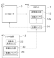
次に、図面を参照して、開示される実施の形態を説明する。図1は、本開示のロボットシステム100の構成を示す斜視図である。図2は、ロボットシステム100の一部の構成を示すブロック図である。図3は、第1実施形態のウエハ治具2の構成を示す平面図である。図4は、図3の状態から電動シリンダ28が押圧部材70を強制的に退避させた様子を示す平面図である。図5は、第1実施形態のウエハ治具2を用いて対象物9を検出する様子を示す部分斜視図である。Next, the disclosed embodiments will be described with reference to the drawings. FIG. 1 is a perspective view showing the configuration of a
図1に示すロボットシステム100は、クリーンルーム等の作業空間内でロボット1に作業を行わせるシステムである。このロボットシステム100は、例えば、ロボット1(具体的には、後述のハンド10)の位置を効率的かつ正確に教示する自動教示を行うことができる。The
ロボットシステム100は、ロボット1と、ウエハ治具(通信治具)2と、コントローラ(制御部)5と、を備える。The
ロボット1は、例えば、図略の保管容器に保管されるウエハ(ワーク)を搬送するウエハ移載ロボットとして機能する。本実施形態では、ロボット1は、SCARA(スカラ)型の水平多関節ロボットによって実現される。SCARAは、Selective Compliance Assembly Robot Armの略称である。The
ロボット1は、図1に示すように、ハンド(エンドエフェクタ)10と、マニピュレータ11と、姿勢検出部12と、を備える。As shown in FIG. 1, the
ハンド10は、エンドエフェクタの一種であって、概ね、平面視でV字状又はU字状に形成されている。ハンド10は、マニピュレータ11(具体的には、後述の第2リンク16)の先端に支持されている。ハンド10は、第2リンク16に対して、上下方向に延びる第3軸c3を中心として回転する。The
ハンド10は、エッジグリップ型のハンドとして構成されている。ハンド10の先端側及び根元側のそれぞれに、ウエハを保持するためのエッジガイド部6が複数設けられている。エッジガイド部6は、円板状のウエハの外周面に接触することができる。The
ハンド10には、押圧機構7が設けられている。押圧機構7は、ハンド10の根元側に配置されている。押圧機構7は、ハンド10の上に載ったウエハの外周面に接触して、ウエハをハンド10の先端側へ押す。この結果、押圧機構7は、ハンド10の先端側のエッジガイド部6との間で、ウエハを挟んで保持することができる。The
押圧機構7は、図3に示すように、押圧部材70と、伝達部材71と、空気圧シリンダ72と、スライド部材73と、位置センサ74と、を備える。As shown in FIG. 3, the
押圧部材70は、ウエハの外周面に接触可能な部材である。押圧部材70は、ハンド10の対称軸A1に沿って移動可能に設けられている。The pressing
押圧部材70には、伝達部材71が連結されている。伝達部材71は、ハンド10の対称軸A1に沿って細長く形成されている。伝達部材71は、ハンド10に形成される孔又は溝の内部に配置されている。伝達部材71は、押圧部材70と空気圧シリンダ72とを連結する。A
空気圧シリンダ72は、伝達部材71を介して押圧部材70を駆動する。空気圧シリンダは、流体圧シリンダの一種である。空気圧シリンダ72に代えて、他の直動アクチュエータを用いることもできる。The pneumatic cylinder 72 drives the pressing
空気圧シリンダ72は、ロッド72aと、シリンダ部材72bと、を備える。The pneumatic cylinder 72 comprises a
ロッド72aは、対称軸A1に沿って配置されている。シリンダ部材72bは中空状に形成され、その内部には、ピストン72cが配置されている。ロッド72aの一部がシリンダ部材72bに差し込まれ、その端部がピストン72cに連結されている。ピストン72cと反対側におけるロッド72aの端部が、伝達部材71に連結されている。シリンダ部材72bは、マニピュレータ11の内部に配置された配管等を介して、図略の圧縮空気源に接続されている。シリンダ部材72bの内部に形成されたシリンダ室に圧縮空気を供給すると、ロッド72aがシリンダ部材72bから進出するように駆動される。この結果、押圧部材70をハンド10の先端に向かって変位させることができる。The
スライド部材73は、ロッド72a又は伝達部材71における適宜の位置に取り付けられている。ハンド10には、図略の案内部材(例えば、レール)が設けられている。この案内部材は、スライド部材73の移動方向を案内する。スライド部材73は、ロッド72a、伝達部材71及び押圧部材70の移動と連動して、対称軸A1に沿って移動することができる。The
位置センサ74は、スライド部材73の位置を検出することができる。位置センサ74は、コントローラ5と電気的に接続されており、検出した押圧部材70の位置情報をコントローラ5に出力する。位置センサ74は、例えば、スライド部材73の可動ストロークの中途にある所定位置を境界として、スライド部材73が所定位置よりもハンド10の先端側に進出していればONとなり、ハンド10の先端側から退避していればOFFとなるように構成することができる。The
押圧部材70が進出状態と退避状態との間で切り換わるのに応じて、押圧部材70の位置が変化する。従って、位置センサ74は、押圧部材70の状態を検出する状態検出部であるということができる。The position of the pressing
マニピュレータ11は、主として、基台13と、昇降軸14、複数のリンク(ここでは、第1リンク15及び第2リンク16)と、を備える。The
基台13は、地面(例えば、クリーンルームの床面)に固定される。基台13は、昇降軸14を支持するベース部材として機能する。The
昇降軸14は、基台13に対して上下方向に移動する。この昇降により、第1リンク15、第2リンク16、及びハンド10の高さを変更することができる。The lifting
第1リンク15は、昇降軸14の上部に支持されている。第1リンク15は、昇降軸14に対して、上下方向に延びる第1軸c1を中心として回転する。これにより、第1リンク15の姿勢を水平面内で変更することができる。The
第2リンク16は、第1リンク15の先端に支持されている。第2リンク16は、第1リンク15に対して、上下方向に延びる第2軸c2を中心として回転する。これにより、第2リンク16の姿勢を水平面内で変更することができる。The
姿勢検出部12は、複数の回転センサ12aを備える。回転センサ12aは、例えば、エンコーダから構成される。それぞれの回転センサ12aは、ハンド10、第1リンク15、第2リンク16を駆動する図略の駆動モータのそれぞれの回転位置を検出する。各回転センサ12aは、コントローラ5と電気的に接続されており、検出された回転位置をコントローラ5に送信する。The
ウエハ治具2は、ウエハを模擬した治具であり、全体として略円板状に形成されている。ウエハ治具2は、図3に示すように、本体21と、対象物検出センサ22と、情報出力部23と、を備える。The
本体21は、円形の平板状に形成されている。本体21の径は、ロボット1が搬送対象とするウエハの径と等しい。本体21の形状がウエハを実質的に模擬していれば良く、本体21の材料がウエハと同一である必要はない。The
対象物検出センサ22は、対象物9を検出するために用いられる。対象物検出センサ22は、例えば、発光部と受光部を備える反射型センサとして構成される。対象物検出センサ22の発光部及び受光部は、本体21の下部であって、円形の本体21の中心部に設けられている。対象物検出センサ22が照射する光の光軸は、本体21の中心軸上に位置する。The
対象物9は、例えば、図5に示すように、細長い円錐台状に形成されている。対象物9は、ハンド10の移動可能範囲内における適宜の場所に、上下に向けて配置される。対象物9の上端の面は、光を反射可能に形成されている。対象物9の上面に、反射シート等が貼られても良い。
As shown in Fig. 5, for example, the
情報出力部23は、ハンド10に設けられた押圧機構7を介して、ハンド10側(即ち、コントローラ5)へ情報を出力するために用いられる。The
本実施形態において、情報出力部23は、直動アクチュエータの一種である電動シリンダ28を備える。電動シリンダ28は、例えば、ボールネジ機構と、ネジ軸を駆動する電動モータと、を用いて構成することができる。しかしながら、情報出力部23の構成はこれに限定されず、例えばソレノイドによって情報出力部23を構成することもできる。In this embodiment, the
電動シリンダ28は、出力ロッド(強制退避部材)28aと、シリンダ部材28bと、を備える。The
出力ロッド28aは、細長い部材として構成される。ウエハ治具2をハンド10に保持したとき、出力ロッド28aは、対称軸A1に沿うように配置される。このとき、出力ロッド28aの先端面は、ハンド10が備える前述の押圧部材70と対向する。The
シリンダ部材28bには、図略の電動モータが配置されている。電動モータは、後述のバッテリー26からの電力で動作する。電動モータの回転により、出力ロッド28aがシリンダ部材28bから進出するように駆動される。出力ロッド28aの移動方向は、ウエハ治具2をハンド10に保持したときに、ハンド10の対称軸A1に沿うように定められる。An electric motor (not shown) is disposed in the
図3に示すように、本実施形態のウエハ治具2は、増幅器25と、バッテリー26と、を更に備える。As shown in FIG. 3, the
増幅器25は、対象物検出センサ22の検出信号を増幅するために用いられる。増幅器25は、本体21の上に設けられている。増幅器25は、対象物検出センサ22及びバッテリー26に電気的に接続されている。増幅器25は、バッテリー26からの電力で動作し、対象物検出センサ22から受信した検出信号を増幅する。増幅された検出信号の電圧は、所定の電圧と、図略の比較器によって比較される。比較器は、比較結果を、動作信号として情報出力部23に出力する。
The
バッテリー26は、対象物検出センサ22、増幅器25及び情報出力部23等に電力を供給する。
The
電動シリンダ28の電動モータは、比較器からの信号が変化するのに応じて駆動され、出力ロッド28aの進出/退避を切り替える。The electric motor of the
出力ロッド28aが退避している図3の状態では、ハンド10の押圧部材70は、ウエハ治具2の本体21の外周面に接触して保持する。従って、ハンド10の位置センサ74はON状態である。In the state shown in FIG. 3 in which the
出力ロッド28aが進出している図4の状態では、出力ロッド28aが、空気圧シリンダ72の押圧力に抗して押圧部材70を強制的に退避させる。従って、ハンド10の位置センサ74はOFF状態である。In the state shown in FIG. 4 in which the
従って、比較器は、情報出力部23(電動シリンダ28)の電動モータを制御して本開示の通信方法を実現するための情報出力制御部として実質的に機能する。 Therefore, the comparator essentially functions as an information output control unit for controlling the electric motor of the information output unit 23 (electric cylinder 28) to realize the communication method of the present disclosure.
上記のように構成されたウエハ治具2は、ハンド10に設けられた押圧機構7の位置センサ74を介して、コントローラ5と通信することができる。詳細は後述する。The
コントローラ5は、CPU、ROM、RAM、補助記憶装置等を備える公知のコンピュータとして構成されている。補助記憶装置は、例えばHDD、SSD等として構成される。補助記憶装置には、ロボット1を制御するためのロボット制御プログラム等が記憶されている。The
コントローラ5は、予め定められる動作プログラム又はユーザから入力される移動指令等に従って、上述のロボット1の各部を駆動するそれぞれの駆動モータに指令値を出力して制御し、予め定められる指令位置にハンド10を移動させる。The
次に、本実施形態のロボットシステム100において、本開示の通信方法により、ウエハ治具2の検出結果から得られたハンド10の検出位置に基づいて、ロボット1への指令位置を補正するロボット教示方法について、詳細に説明する。Next, a detailed description will be given of a robot teaching method in the
ウエハ治具2は、非使用時には、適宜の保管位置に保管されている。ロボット1は、コントローラ5からの制御指令に応じて、保管位置にあるウエハ治具2を保持する(第1工程)。この状態が図3に示されている。When not in use, the
ウエハ治具2がハンド10によって保持される前は、ウエハ治具2の情報出力部23において、電動シリンダ28の出力ロッド28aは退避状態となっている。出力ロッド28aの先端面は、本体21の外縁よりも内側に位置している。押圧機構7の押圧部材70は、ハンド10の先端側に進出して、ウエハ治具2の本体21に接触して押圧する。ウエハ治具2がハンド10によって保持された状態では、押圧部材70は進出側に移動しているので、位置センサ74はON状態である。Before the
ロボット1は、保持したウエハ治具2を所定の位置へ搬送する。搬送後、ウエハ治具2の対象物検出センサ22は、対象物9の近傍に位置している。The
その後、ロボット1は、ウエハ治具2とともにハンド10を、平面視で適当な範囲内で様々な方向に動かしながら、対象物9を対象物検出センサ22によって走査する。本実施形態において、対象物9の上面の形状は円形状となっている。従って、その円の少なくとも3点の位置を対象物検出センサ22で検知できれば、円の中心を特定できる。本実施形態では、平面視で、対象物9の上面の円の中心が、後述の位置補正のための基準位置となっている。Thereafter, the
この走査の過程で、ウエハ治具2において、対象物検出センサ22により対象物9が検出されると、電動シリンダ28の電動モータが動作し、出力ロッド28aが図4に示すようにハンド10の根元側へ進出する(第2工程)。本体21xの外縁から突出する出力ロッド28aによって、押圧部材70が図5の太線矢印で示すように退避側に押し込まれる。この結果、位置センサ74はON状態からOFF状態に切り換わる。従って、コントローラ5は、対象物検出センサ22による対象物9の検知の有無を、位置センサ74を通じて認識することができる。During this scanning process, when the
ロボット1の公差等によって、ロボット1に指令したハンド10の位置と、ハンド10の実際の位置との間にズレが生じる場合がある。本実施形態によれば、ウエハ治具2によって対象物9を走査した結果に基づいて上記のズレを特定し、ロボット1への指令位置を補正することができる。Due to the tolerance of the
以下、簡単に説明する。コントローラ5は、対象物9を対象物検出センサ22で検知した3点のそれぞれに相当する、ロボット1への指令位置を予め記憶している。コントローラ5は、3点の指令位置を通過する円の中心に相当する指令位置を、公知の方法で計算する。このように計算された指令位置と、ハンド10の中心を対象物9の中心と一致させるために従前に使われていた指令位置と、の間にズレがある場合、コントローラ5は、このズレ量を計算で取得する。このズレ量は、例えば平面ベクトルで表すことができる。コントローラ5は、元の指令位置からズレ量のベクトルを減算することで、指令位置のオフセットを補正する。補正後の指令位置をコントローラ5がロボット1に与えることにより、ロボット1の動作精度を高めることができる。
A brief explanation is given below. The
ウエハ治具2はウエハを模した形状となっているので、ハンド10はウエハ治具2を、通常のウエハと同様に取り扱うことができる。従って、上述した走査及び位置補正の一連の動作を自動的に行うことが容易である。
Because the
ウエハ治具2は、押圧機構7の位置センサ74を介して、対象物検出センサ22により対象物9が検出されたことをコントローラ5に通知する。このように、電動シリンダ28の出力ロッド28aが押圧機構7の押圧部材70を押し込んで退避させることで情報の伝達が行われるので、ウエハ治具2とハンド10とを繋ぐ電気ケーブルを不要とすることができる。これにより、構成の簡素化、軽量化を実現することができる。また、電気ケーブルが不要になるので、塵埃の発生を抑制することができる。更に、ロボットが従来から備えることが多い押圧機構7を使用する構成であるので、既存のロボットへの適用も容易である。The
以上に説明したように、本実施形態のウエハ治具2は、ハンド10と、位置センサ74と、を備えるロボット1に用いられる。ハンド10は、ウエハを搬送可能である。位置センサ74は、ハンド10においてウエハを保持する押圧部材70の状態を検出する。ウエハ治具2は、ハンド10側へ情報を出力するための情報出力部23を備える。情報出力部23は、位置センサ74の検出結果を変化させることにより、位置センサ74を介してハンド10側へ情報を出力する。As described above, the
これにより、ウエハ治具2が、ロボット1が備える構成の一部(押圧機構7)を利用して、ロボット1と通信することが可能になる。通信ケーブルが不要になるため、ウエハ治具2の小型化、簡素化、軽量化を実現できるとともに、ロボット1の動きの自由度を好適に維持することができる。This allows the
また、本実施形態のウエハ治具2は、対象物9を検出する対象物検出センサ22を備える。情報出力部23は、対象物検出センサ22が対象物9を検出したか否かを、情報として出力する。In addition, the
これにより、ウエハ治具2側で対象物9を検出したか否かを、ロボット1側で認識することができる。This allows the
また、本実施形態では、対象物検出センサ22は、当該ウエハ治具2の中心に設けられている。
In addition, in this embodiment, the
これにより、ウエハ治具2の中心に対応する位置から対象物9を検出することになるので、対象物9を検出したウエハ治具2の位置を正確に把握することができる。This allows the
また、本実施形態では、ハンド10によりウエハ治具2が保持された状態において、対象物検出センサ22はハンド10の中心に位置する。
In addition, in this embodiment, when the
これにより、位置制御の基準として用いられることが多いハンド10の中心位置における検出結果を得ることができる。従って、例えば、検出結果を位置制御のために用いることで、ロボット1の動作精度を高めることができる。This makes it possible to obtain detection results at the center position of the
また、本実施形態のウエハ治具2において、ハンド10は、ウエハを押圧する押圧部材70を備える。位置センサ74は、押圧部材70の位置を検出する。In addition, in the
これにより、簡素な構成でウエハ治具2側から情報を送信することができる。This allows information to be transmitted from the
また、本実施形態のウエハ治具2において、情報出力部23は、電動シリンダの動作によって情報を出力する。
In addition, in the
これにより、例えば圧縮空気源からの配管をウエハ治具2に接続しなくても、バッテリー26から供給される電気エネルギーを用いて、コントローラ5との通信を行うことができる。従って、ウエハ治具2の取扱いが容易になる。This allows communication with the
次に、第2実施形態を説明する。図6は、第2実施形態のウエハ治具2xの構成を示す平面図である。図7は、第2実施形態のウエハ治具2xの構成を示す一部断面模式図である。なお、本実施形態の説明においては、前述の実施形態と同一又は類似の部材には図面に同一の符号を付し、説明を省略する場合がある。Next, a second embodiment will be described. FIG. 6 is a plan view showing the configuration of a
本実施形態のロボットは、吸着グリップ型のハンド10xを備える。ハンド10xには、図6に示すように、ウエハを吸着して保持するための吸引口17が複数(本実施形態においては3つ)形成されている。それぞれの吸引口17は、負圧流路(経路)80を介して、負圧源8と接続されている。負圧流路80の途中には、負圧センサ81が接続されている。The robot of this embodiment is equipped with a suction
負圧センサ81は、負圧用の圧力センサとして構成される。負圧センサ81は、コントローラ5と電気的に接続されており、検出した圧力をコントローラ5に送信する。負圧センサ81は、ハンド10xがウエハを吸着する負圧の状態を検出する状態検出部の一種である。The
ウエハ治具2xは、本体21xを備える。本体21xには貫通孔21aが形成されている。The
この貫通孔21aは、3つの吸引口17のうち1つに対応する位置に設けられている。具体的には、貫通孔21aは、ハンド10xの手首部に近い側の吸引口17に対応して形成されている。図7に示すように、ウエハ治具2xがハンド10xにより保持された状態において、吸引口17の内部空間と、貫通孔21aの内部空間と、が接続される。This through
ウエハ治具2xは、情報出力部23xを備える。情報出力部23xは、空気シリンダ27と、電動シリンダ(アクチュエータ)29と、を備える。The
空気シリンダ27は、図7に示すように、中空状のシリンダ部材27aを備える。シリンダ部材27aの内部には、ピストン27bが軸方向移動可能に配置されている。シリンダ部材27aの内部空間は、ピストン27bによって2つに区画される。区画された一側の空間である接続室27cは、前述の貫通孔21aに接続されている。
As shown in Fig. 7, the
電動シリンダ29は、例えばボールネジ機構及び電動モータを用いて構成することができる。電動シリンダ29のロッド29aの先端が、空気シリンダ27のシリンダ部材27aの内部に差し込まれて、ピストン27bに固定されている。The
この構成で、ハンド10xがウエハ治具2xを保持すると、吸引口17は、貫通孔21aを介して接続室27cと接続される。
In this configuration, when the
ロボット1は、ウエハ治具2xとともにハンド10xを、平面視で適当な範囲内で様々な方向に動かしながら、対象物9を対象物検出センサ22によって走査する。対象物検出センサ22が対象物9を検出した場合、電動シリンダ29が駆動され、空気シリンダ27におけるピストン27bを適宜のストロークで往復移動させる。この結果、接続室27cの容積が変化するので、負圧流路80の負圧が強くなったり弱くなったりする。負圧センサ81は、この圧力変化を検出する。このように、コントローラ5は、対象物検出センサ22による対象物9の検知の有無を、負圧センサ81を通じて認識することができる。The
以上に説明したように、本実施形態において、ハンド10xには、ウエハを吸着可能な吸引口17が形成される。ロボット1は、吸引口17と負圧源8とを繋ぐ負圧流路80の負圧を検出する負圧センサ81を備える。ウエハ治具2xは、ハンド10xによって吸着されるときに吸引口17に接続される接続室27cを備える。ウエハ治具2xの情報出力部23xは、接続室27cの容積を変更する電動シリンダ29を備える。As described above, in this embodiment, the
これにより、ウエハを吸着する負圧を利用して、情報をウエハ治具2xからコントローラ5へ伝達することができる。This allows information to be transmitted from the
以上に本開示の好適な実施の形態を説明したが、上記の構成は例えば以下のように変更することができる。 Although a preferred embodiment of the present disclosure has been described above, the above configuration can be modified, for example, as follows:
対象物検出センサ22は、非接触型のセンサであっても良いし、接触型であっても良い。The
ウエハ治具2,2xは、対象物9の検出以外の目的(言い換えれば、ロボット1の位置補正以外の目的)で用いられても良い。
The
バッテリー26は、1次電池として構成することも、2次電池として構成することもできる。バッテリー26を2次電池として構成した場合、ウエハ治具2の保管位置又は別の位置に、バッテリー26への充電を行うための充電装置が配置されることが好ましい。これにより、自動充電を実現することができる。The
本明細書で開示する要素の機能は、開示された機能を実行するように構成又はプログラムされた汎用プロセッサ、専用プロセッサ、集積回路、ASIC(Application Specific Integrated Circuits)、従来の回路、及び/又は、それらの組合せ、を含む回路又は処理回路を使用して実行することができる。プロセッサは、トランジスタやその他の回路を含むため、処理回路又は回路と見なされる。本開示において、回路、ユニット、又は手段は、列挙された機能を実行するハードウェア、又は、列挙された機能を実行するようにプログラムされたハードウェアである。ハードウェアは、本明細書に開示されているハードウェアであっても良いし、あるいは、列挙された機能を実行するようにプログラム又は構成されているその他の既知のハードウェアであっても良い。ハードウェアが回路の一種と考えられるプロセッサである場合、回路、手段、又はユニットはハードウェアとソフトウェアの組合せであり、ソフトウェアはハードウェア及び/又はプロセッサの構成に使用される。The functions of the elements disclosed herein can be performed using circuits or processing circuits, including general purpose processors, special purpose processors, integrated circuits, ASICs (Application Specific Integrated Circuits), conventional circuits, and/or combinations thereof, configured or programmed to perform the disclosed functions. A processor is considered a processing circuit or circuit because it includes transistors and other circuits. In this disclosure, a circuit, unit, or means is hardware that performs the recited functions or hardware that is programmed to perform the recited functions. The hardware may be hardware disclosed herein or other known hardware that is programmed or configured to perform the recited functions. When the hardware is a processor, which is considered a type of circuit, the circuit, means, or unit is a combination of hardware and software, and the software is used to configure the hardware and/or the processor.
Claims (9)
前記ハンドがウエハを保持する部材の状態、又は、前記ハンドがウエハを吸着する負圧の状態を検出する状態検出部と、
を備えるロボットに用いられるウエハ治具であって、
前記ハンド側へ情報を出力するための情報出力部を備え、
前記情報出力部は、前記状態検出部の検出結果を変化させることにより、当該状態検出部を介して、前記ハンド側へ情報を出力し、
前記ハンドは、前記ウエハを押圧する押圧部材を備え、
前記状態検出部は、前記押圧部材の位置を検出する位置センサであり、
前記情報出力部は、前記押圧部材を押圧に抗して退避させるアクチュエータを備えることを特徴とするウエハ治具。 A hand capable of transporting a wafer;
a state detection unit that detects a state of a member that holds the wafer by the hand or a state of a negative pressure that the hand adsorbs the wafer;
A wafer jig for use in a robot comprising:
an information output unit for outputting information to the hand side,
the information output unit outputs information to the hand side via the state detection unit by changing a detection result of the state detection unit;
the hand includes a pressing member that presses the wafer,
the state detection unit is a position sensor that detects a position of the pressing member,
The wafer jig , wherein the information output section includes an actuator for retracting the pressing member against a pressing force .
前記ハンドがウエハを保持する部材の状態、又は、前記ハンドがウエハを吸着する負圧の状態を検出する状態検出部と、
を備えるロボットに用いられるウエハ治具であって、
前記ハンド側へ情報を出力するための情報出力部を備え、
前記情報出力部は、前記状態検出部の検出結果を変化させることにより、当該状態検出部を介して、前記ハンド側へ情報を出力し、
前記ハンドには、ウエハを吸着可能な吸引口が形成され、
前記状態検出部は、前記吸引口と負圧源とを繋ぐ経路の負圧を検出する負圧センサであり、
前記ウエハ治具は、前記ハンドによって吸着されるときに前記吸引口に接続される接続室を備え、
前記情報出力部は、前記接続室の容積を変更するアクチュエータを備えることを特徴とするウエハ治具。 A hand capable of transporting a wafer;
a state detection unit that detects a state of a member that holds the wafer by the hand or a state of a negative pressure that the hand adsorbs the wafer;
A wafer jig for use in a robot comprising:
an information output unit for outputting information to the hand side,
the information output unit outputs information to the hand side via the state detection unit by changing a detection result of the state detection unit;
The hand is provided with a suction port capable of suctioning a wafer,
the state detection unit is a negative pressure sensor that detects a negative pressure in a path connecting the suction port and a negative pressure source,
the wafer jig includes a connection chamber that is connected to the suction port when the wafer jig is sucked by the hand,
The wafer jig , wherein the information output unit includes an actuator for changing a volume of the connection chamber .
前記ハンドがウエハを保持する部材の状態、又は、前記ハンドがウエハを吸着する負圧の状態を検出する状態検出部と、
を備えるロボットに用いられるウエハ治具であって、
前記ハンド側へ情報を出力するための情報出力部を備え、
前記情報出力部は、前記状態検出部の検出結果を変化させることにより、当該状態検出部を介して、前記ハンド側へ情報を出力し、
前記情報出力部は、電動アクチュエータの動作によって情報を出力することを特徴とするウエハ治具。 A hand capable of transporting a wafer;
a state detection unit that detects a state of a member that holds the wafer by the hand or a state of a negative pressure that the hand adsorbs the wafer;
A wafer jig for use in a robot comprising:
an information output unit for outputting information to the hand side,
the information output unit outputs information to the hand side via the state detection unit by changing a detection result of the state detection unit;
The wafer jig , wherein the information output unit outputs information by the operation of an electric actuator .
対象物を検出する対象物検出センサを備え、
前記情報出力部は、前記対象物検出センサが前記対象物を検出したか否かを、前記情報として出力することを特徴とするウエハ治具。 The wafer jig according to any one of claims 1 to 3 ,
An object detection sensor is provided to detect an object,
The wafer jig, wherein the information output section outputs, as the information, whether or not the object detection sensor has detected the object.
前記対象物検出センサは、当該ウエハ治具の中心に設けられていることを特徴とするウエハ治具。 5. The wafer jig according to claim 4 ,
A wafer jig, wherein the object detection sensor is provided at the center of the wafer jig.
前記ハンドにより前記ウエハ治具が保持された状態において、前記対象物検出センサは、前記ハンドの中心に位置することを特徴とするウエハ治具。 6. The wafer jig according to claim 5 ,
A wafer jig, characterized in that, when the wafer jig is held by the hand, the object detection sensor is located at the center of the hand.
前記ハンドによって前記ウエハ治具を保持可能なロボットと、
前記ロボットに指令を与えて制御する制御部と、
を備え、
前記制御部は、前記状態検出部を介して、前記ウエハ治具側から情報を受信することを特徴とするロボットシステム。 A wafer jig according to any one of claims 1 to 3 ;
a robot capable of holding the wafer jig by the hand;
A control unit that issues commands to the robot to control it;
Equipped with
The robot system according to claim 1, wherein the control unit receives information from the wafer jig via the state detection unit.
前記ハンドにより保持されることが可能なウエハ治具と、
の間で、前記ウエハ治具が前記ハンド側へ情報を送信する通信方法であって、
前記ウエハ治具が前記ハンドにより保持された状態とする第1工程と、
前記ウエハ治具が備える情報出力部が、前記情報に応じて、前記状態検出部の検出結果を変化させる第2工程と、
を含み、
前記ハンドは、前記ウエハを押圧する押圧部材を備え、
前記状態検出部は、前記押圧部材の位置を検出する位置センサであり、
前記情報出力部は、前記押圧部材を押圧に抗して退避させるアクチュエータを備えることを特徴とする通信方法。 a robot including a state detection unit capable of detecting a state of a member that holds a wafer by a hand capable of transporting a wafer, or a state of a negative pressure at which the hand adsorbs a wafer;
a wafer jig capable of being held by the hand;
A communication method in which the wafer jig transmits information to the hand side,
a first step of holding the wafer jig by the hand;
a second step in which an information output unit included in the wafer jig changes a detection result of the state detection unit in response to the information;
Including,
the hand includes a pressing member that presses the wafer,
the state detection unit is a position sensor that detects a position of the pressing member,
The communication method according to the present invention, wherein the information output unit includes an actuator that retracts the pressing member against a pressing force .
Applications Claiming Priority (3)
| Application Number | Priority Date | Filing Date | Title |
|---|---|---|---|
| US17/131,082 | 2020-12-22 | ||
| US17/131,082 US11845179B2 (en) | 2020-12-22 | 2020-12-22 | Wafer jig, robot system, communication method, and robot teaching method |
| PCT/JP2021/042427 WO2022137918A1 (en) | 2020-12-22 | 2021-11-18 | Wafer jig, robot system, communication method, and robot teaching method |
Publications (2)
| Publication Number | Publication Date |
|---|---|
| JPWO2022137918A1 JPWO2022137918A1 (en) | 2022-06-30 |
| JP7588943B2 true JP7588943B2 (en) | 2024-11-25 |
Family
ID=82023942
Family Applications (1)
| Application Number | Title | Priority Date | Filing Date |
|---|---|---|---|
| JP2022571972A Active JP7588943B2 (en) | 2020-12-22 | 2021-11-18 | Wafer jig, robot system, communication method, and robot teaching method |
Country Status (6)
| Country | Link |
|---|---|
| US (1) | US11845179B2 (en) |
| JP (1) | JP7588943B2 (en) |
| KR (1) | KR20230144527A (en) |
| CN (1) | CN116918055A (en) |
| TW (1) | TWI791355B (en) |
| WO (1) | WO2022137918A1 (en) |
Families Citing this family (3)
| Publication number | Priority date | Publication date | Assignee | Title |
|---|---|---|---|---|
| US11654578B2 (en) * | 2020-09-17 | 2023-05-23 | Kawasaki Jukogyo Kabushiki Kaisha | Robot system and offset acquisition method |
| JP7660006B2 (en) * | 2021-03-24 | 2025-04-10 | 株式会社Screenホールディングス | SUBSTRATE PROCESSING APPARATUS, TEACHING INFORMATION GENERATION METHOD, AND TEACHING SET |
| JP2024078532A (en) * | 2022-11-30 | 2024-06-11 | 株式会社安川電機 | Substrate transport robot system and method for teaching substrate transport robot |
Citations (3)
| Publication number | Priority date | Publication date | Assignee | Title |
|---|---|---|---|---|
| JP2006332543A (en) | 2005-05-30 | 2006-12-07 | Dainippon Screen Mfg Co Ltd | Substrate conveyance teaching method and substrate transport device |
| JP2010137300A (en) | 2008-12-09 | 2010-06-24 | Yaskawa Electric Corp | Manipulator for substrate conveyance taught by teaching tool |
| WO2020137991A1 (en) | 2018-12-27 | 2020-07-02 | 川崎重工業株式会社 | Substrate transporting robot and automated teaching method |
Family Cites Families (21)
| Publication number | Priority date | Publication date | Assignee | Title |
|---|---|---|---|---|
| JPH05102056A (en) * | 1991-10-11 | 1993-04-23 | Rohm Co Ltd | Wafer support |
| WO2000033359A2 (en) * | 1998-12-02 | 2000-06-08 | Kensington Laboratories, Inc. | Specimen holding robotic arm end effector |
| US6615113B2 (en) * | 2001-07-13 | 2003-09-02 | Tru-Si Technologies, Inc. | Articles holders with sensors detecting a type of article held by the holder |
| US7140655B2 (en) * | 2001-09-04 | 2006-11-28 | Multimetrixs Llc | Precision soft-touch gripping mechanism for flat objects |
| CN100431806C (en) * | 2001-09-07 | 2008-11-12 | 株式会社安川电机 | Wafer position teaching method and jig for teaching |
| US6678581B2 (en) * | 2002-01-14 | 2004-01-13 | Taiwan Semiconductor Manufacturing Co. Ltd | Method of calibrating a wafer edge gripping end effector |
| JP3888620B2 (en) * | 2002-01-22 | 2007-03-07 | 東京エレクトロン株式会社 | Substrate delivery position detection method and teaching device in substrate transport apparatus |
| US6813543B2 (en) * | 2002-10-08 | 2004-11-02 | Brooks-Pri Automation, Inc. | Substrate handling system for aligning and orienting substrates during a transfer operation |
| JP4064361B2 (en) * | 2004-03-15 | 2008-03-19 | 川崎重工業株式会社 | Method for acquiring position information of transfer position of transfer device |
| JP4047826B2 (en) * | 2004-03-25 | 2008-02-13 | 東京エレクトロン株式会社 | Vertical heat treatment apparatus and automatic teaching method for transfer mechanism |
| EP2298509B1 (en) * | 2008-05-27 | 2021-08-25 | Rorze Corporation | Transport apparatus and position-teaching method |
| US8970820B2 (en) * | 2009-05-20 | 2015-03-03 | Nikon Corporation | Object exchange method, exposure method, carrier system, exposure apparatus, and device manufacturing method |
| US8792084B2 (en) * | 2009-05-20 | 2014-07-29 | Nikon Corporation | Exposure apparatus, exposure method, and device manufacturing method |
| JP5447431B2 (en) * | 2011-05-09 | 2014-03-19 | 株式会社安川電機 | Robot system |
| JP6042564B2 (en) * | 2013-12-06 | 2016-12-14 | エーファウ・グループ・エー・タルナー・ゲーエムベーハー | Apparatus and method for aligning substrates |
| JP6384195B2 (en) * | 2014-08-20 | 2018-09-05 | 株式会社安川電機 | Robot system and robot teaching method |
| US10395956B2 (en) * | 2016-03-04 | 2019-08-27 | Kawasaski Jukogyo Kabushiki Kaisha | Substrate transfer apparatus and method of teaching substrate transfer robot |
| JP2018069413A (en) * | 2016-11-01 | 2018-05-10 | セイコーエプソン株式会社 | Robot system |
| JP2019155536A (en) * | 2018-03-13 | 2019-09-19 | 株式会社東芝 | Holding device, flight body, and conveyance system |
| US10923375B2 (en) * | 2018-11-28 | 2021-02-16 | Brooks Automation, Inc. | Load port module |
| CN113874173B (en) * | 2019-02-08 | 2025-02-14 | 安川美国有限公司 | Through-beam automatic teaching |
-
2020
- 2020-12-22 US US17/131,082 patent/US11845179B2/en active Active
-
2021
- 2021-11-18 JP JP2022571972A patent/JP7588943B2/en active Active
- 2021-11-18 WO PCT/JP2021/042427 patent/WO2022137918A1/en not_active Ceased
- 2021-11-18 KR KR1020237023408A patent/KR20230144527A/en not_active Withdrawn
- 2021-11-18 CN CN202180085676.3A patent/CN116918055A/en active Pending
- 2021-12-22 TW TW110148038A patent/TWI791355B/en active
Patent Citations (3)
| Publication number | Priority date | Publication date | Assignee | Title |
|---|---|---|---|---|
| JP2006332543A (en) | 2005-05-30 | 2006-12-07 | Dainippon Screen Mfg Co Ltd | Substrate conveyance teaching method and substrate transport device |
| JP2010137300A (en) | 2008-12-09 | 2010-06-24 | Yaskawa Electric Corp | Manipulator for substrate conveyance taught by teaching tool |
| WO2020137991A1 (en) | 2018-12-27 | 2020-07-02 | 川崎重工業株式会社 | Substrate transporting robot and automated teaching method |
Also Published As
| Publication number | Publication date |
|---|---|
| WO2022137918A1 (en) | 2022-06-30 |
| US11845179B2 (en) | 2023-12-19 |
| JPWO2022137918A1 (en) | 2022-06-30 |
| TW202228948A (en) | 2022-08-01 |
| TWI791355B (en) | 2023-02-01 |
| US20220193917A1 (en) | 2022-06-23 |
| KR20230144527A (en) | 2023-10-16 |
| CN116918055A (en) | 2023-10-20 |
Similar Documents
| Publication | Publication Date | Title |
|---|---|---|
| JP7588943B2 (en) | Wafer jig, robot system, communication method, and robot teaching method | |
| US7445260B2 (en) | Gripping type hand | |
| US9156160B2 (en) | Robot system, calibration method, and method for producing to-be-processed material | |
| TWI696537B (en) | Substrate transfer robot and its operation method | |
| US20140277722A1 (en) | Robot system, calibration method, and method for producing to-be-processed material | |
| US12275601B2 (en) | Wafer transfer apparatus and wafer transfer method | |
| US20200368862A1 (en) | Connecting device and connecting method | |
| JP2005286019A (en) | Substrate gripping device | |
| JP7340010B2 (en) | SUBSTRATE TRANSFER ROBOT AND SUBSTRATE TRANSFER METHOD | |
| TW201806067A (en) | Sensor based auto-calibration wafer | |
| US6752442B2 (en) | Workpiece handling end-effector and a method for processing workpieces using a workpiece handling end-effector | |
| JP7576631B2 (en) | Wafer jig, robot system, communication method, and robot teaching method | |
| WO2018139574A1 (en) | Conveyance system and operation method thereof | |
| US12508722B2 (en) | Holding device, control method, control device, and robot system | |
| US20230116525A1 (en) | Substrate holding hand and substrate transferring robot | |
| JP2002264065A (en) | Wafer transfer robot | |
| KR200436002Y1 (en) | Double arm robot | |
| KR102810077B1 (en) | Industrial robot and industrial robot teaching method | |
| US10867821B2 (en) | Substrate transfer robot and method of teaching edge position of target body | |
| JP7550042B2 (en) | Robot and teaching method | |
| US20250375879A1 (en) | Robot system, robot control method, and robot control program | |
| JP2022142908A (en) | Robot hand and control method of robot hand |
Legal Events
| Date | Code | Title | Description |
|---|---|---|---|
| A621 | Written request for application examination |
Free format text: JAPANESE INTERMEDIATE CODE: A621 Effective date: 20230523 |
|
| A131 | Notification of reasons for refusal |
Free format text: JAPANESE INTERMEDIATE CODE: A131 Effective date: 20240711 |
|
| A521 | Request for written amendment filed |
Free format text: JAPANESE INTERMEDIATE CODE: A523 Effective date: 20240829 |
|
| TRDD | Decision of grant or rejection written | ||
| A01 | Written decision to grant a patent or to grant a registration (utility model) |
Free format text: JAPANESE INTERMEDIATE CODE: A01 Effective date: 20241112 |
|
| A61 | First payment of annual fees (during grant procedure) |
Free format text: JAPANESE INTERMEDIATE CODE: A61 Effective date: 20241112 |
|
| R150 | Certificate of patent or registration of utility model |
Ref document number: 7588943 Country of ref document: JP Free format text: JAPANESE INTERMEDIATE CODE: R150 |