JP7588939B2 - Tunnel Construction System - Google Patents
Tunnel Construction System Download PDFInfo
- Publication number
- JP7588939B2 JP7588939B2 JP2021001319A JP2021001319A JP7588939B2 JP 7588939 B2 JP7588939 B2 JP 7588939B2 JP 2021001319 A JP2021001319 A JP 2021001319A JP 2021001319 A JP2021001319 A JP 2021001319A JP 7588939 B2 JP7588939 B2 JP 7588939B2
- Authority
- JP
- Japan
- Prior art keywords
- marker
- markers
- virtual
- normal
- self
- Prior art date
- Legal status (The legal status is an assumption and is not a legal conclusion. Google has not performed a legal analysis and makes no representation as to the accuracy of the status listed.)
- Active
Links
- 238000010276 construction Methods 0.000 title claims description 14
- 239000003550 marker Substances 0.000 claims description 118
- 239000007921 spray Substances 0.000 claims description 19
- 230000004397 blinking Effects 0.000 description 30
- 238000000034 method Methods 0.000 description 12
- 238000009434 installation Methods 0.000 description 11
- 238000010586 diagram Methods 0.000 description 10
- 238000001514 detection method Methods 0.000 description 8
- 238000005516 engineering process Methods 0.000 description 7
- 229910000831 Steel Inorganic materials 0.000 description 6
- 239000010959 steel Substances 0.000 description 6
- 238000004891 communication Methods 0.000 description 4
- 238000005507 spraying Methods 0.000 description 3
- 230000003321 amplification Effects 0.000 description 2
- 238000007796 conventional method Methods 0.000 description 2
- 239000000428 dust Substances 0.000 description 2
- 238000007667 floating Methods 0.000 description 2
- 230000006870 function Effects 0.000 description 2
- 238000003199 nucleic acid amplification method Methods 0.000 description 2
- 230000003287 optical effect Effects 0.000 description 2
- 230000008569 process Effects 0.000 description 2
- 238000002310 reflectometry Methods 0.000 description 2
- XLYOFNOQVPJJNP-UHFFFAOYSA-N water Substances O XLYOFNOQVPJJNP-UHFFFAOYSA-N 0.000 description 2
- 238000009412 basement excavation Methods 0.000 description 1
- 238000005452 bending Methods 0.000 description 1
- 230000008901 benefit Effects 0.000 description 1
- 230000005540 biological transmission Effects 0.000 description 1
- 230000000694 effects Effects 0.000 description 1
- 239000000463 material Substances 0.000 description 1
- 230000007246 mechanism Effects 0.000 description 1
- 239000002184 metal Substances 0.000 description 1
- 230000002093 peripheral effect Effects 0.000 description 1
- 230000004044 response Effects 0.000 description 1
Images


Landscapes
- Lining And Supports For Tunnels (AREA)
Description
本発明はトンネル施工の支保工建込みなどを行う施工システムに係り、特にトンネル施工の支保工建込みにおける支保工建て込み位置及びコンクリート吹き付け位置などの位置検出システムに関するものである。
The present invention relates to a construction system for erecting shoring in tunnel construction, and more particularly to a position detection system for detecting the position of shoring erection and the position of concrete spraying in erecting shoring in tunnel construction.
一般的にトンネル施工においては、トンネル掘削後、掘削したトンネル内部が崩れないようにアーチ状の鋼製の支え(支保工と称されている)を一定間隔で配置する。
前記支保工は、掘削後のトンネル断面の崩落を防ぎ、断面を安定的に支保する役割を有するものである。
In general, in tunnel construction, after the tunnel is excavated, arch-shaped steel supports (known as shoring) are placed at regular intervals to prevent the inside of the excavated tunnel from collapsing.
The support structure has the role of preventing the collapse of the tunnel cross section after excavation and of providing stable support for the cross section.
ここで、鋼製の支保工は、H形鋼と呼ばれる鋼材をトンネルのアーチ形状に曲げて作製される。例えば、左右2つの支保工部材を中央上部(天端)で繋ぎ合わせてアーチ状の支保工を形成し、これをトンネルの断面に沿って建て込む。これら支保工は所定の間隔をあけてトンネル内に複数箇所建て込まれる。そして、トンネル内の地山にコンクリートが吹き付けられ、トンネル内地山の強化が図られるものとなる。 The steel supports are made by bending steel material called H-shaped steel into the arch shape of the tunnel. For example, two support members on the left and right are connected at the top center (top) to form an arch-shaped support, which is then erected along the cross section of the tunnel. These supports are erected in multiple places within the tunnel at specified intervals. Concrete is then sprayed onto the ground inside the tunnel to strengthen it.
前記支保工の建込みにはエレクターと呼ばれる専用の建機が用いられる。エレクターには、支保工を掴むクランプを先端に備えたブームの他、作業者が載って作業するためのバスケット6が搭載される。
また、エレクターには、その後の工程で用いられるコンクリート吹付機が一体になって形成されたものも存在する。
A special construction machine called an erector is used to erect the shoring. The erector is equipped with a boom equipped with a clamp at the tip to grip the shoring, and a basket 6 for workers to stand on and work on.
In addition, some erectors are integrated with concrete sprayers that are used in subsequent processes.
前述したように、支保工の建込みに際しては、左右の支保工部材を天端部で例えばボルト・ナットなどの連結具にて繋ぎ合わせる必要があり、該作業は作業者がバスケット6に載って行う。また、タイロッドと呼ばれる支保工と支保工の間隔を一定に保つ位置合わせの為の金具を挿入する作業も行われる。 As mentioned above, when erecting the shoring, it is necessary to connect the left and right shoring members at the top end with connectors such as bolts and nuts, and this work is carried out by a worker standing on the basket 6. In addition, the work of inserting metal fittings called tie rods to keep the distance between the shorings constant and to align them is also carried out.
これら作業は高所作業であるだけでなく、常に崩落の危険性が伴うトンネル切羽直下での作業のため作業者の安全を確保することが重要であると共に、前記支保工の建て込み位置の安全かつ正確な位置検出を行うことなどが課題とされている。 Not only is this work done at height, but it is also done directly below the tunnel face, where there is a constant risk of collapse, so it is important to ensure the safety of the workers, and another challenge is to safely and accurately detect the position of the support structure.
ここで、支保工建込み位置検出などを行うトンネル施工システムに関する従来技術としては、鋼製支保工建込みロボットを使用して行うシステムが一般的に知られている。
この従来技術は、支保工にプリズムを取り付け、例えば後方のトータルステーションからレーザー光を投射することで位置を測量する。そして、トータルステーションには、プリズムの自動検出/追尾機能付きの機器を使用して支保工の建て込みが行われる。
Here, as a conventional technique for a tunnel construction system that detects the position of shoring installation, etc., a system that uses a steel shoring installation robot is generally known.
In this conventional technology, a prism is attached to the support and its position is measured by projecting a laser beam from a total station behind it.The total station then uses equipment with an automatic prism detection/tracking function to erect the support.
支保工は1~1.5m間隔で配置され、建て込まれるが、建込み後には支保工に取り付けられたプリズムは、その価格が高額であるため再度の使用に供するものとして回収される。回収方法は、作業者が手で取り外すか、もしくはワイヤ等を予め取り付けておき、設置後に引っ張って外す。そのため、従来の前記システムでは作業者の安全が完全には確保されていないとの課題と共に、従来システムで使用されるロボットは費用が極めて高額であるとの課題もあった。
The supports are placed at intervals of 1 to 1.5 m and erected, but after erection, the prisms attached to the supports are collected for reuse due to their high price. They are either removed by hand by workers, or a wire is attached in advance and pulled out after installation. Therefore, the conventional system has the problem that the safety of workers is not completely ensured, and the robots used in the conventional system are extremely expensive.
かくして、本発明は前記従来の課題を解決するために創案されたものであり、支保工建て込み作業を行う作業者の安全が確保できると共に、確実、迅速、容易に支保工の建て込み作業などが行え、従来の様にプリズムを回収する作業も必要とせず、かつ建て込み作業などの作業コストを極めて安価にしうるトンネル施工システムを提供することを目的とするものである。
Thus, the present invention has been devised to solve the above-mentioned problems of the conventional art, and aims to provide a tunnel construction system which ensures the safety of workers performing support erection work, enables support erection work to be performed reliably, quickly and easily, does not require the work of retrieving prisms as in the conventional art, and can reduce the labor costs of erection work and the like extremely.
本発明は、
エレクターの幅方向両側から揺動可能に突設する少なくとも一対のブームと、該少なくとも一対のブームの先端に取り付けられたクランプと、該クランプが各々握持する支保工部材と、支保工部材の長手方向両端側に少なくとも2個取り付けられ、照射された近赤外線光を反射する仮想マーカと、
可動するブームに設けられたクランプあるいは吹付ノズルに取り付けられ、異なる点滅周期が与えられて各々個別認識できると共に、各々の取り付け位置が認識できる点滅自発光型の構成を有する通常マーカと、
前記仮想マーカ及び通常マーカからの光を取得する間隔をあけて設置された複数の近赤外線カメラと、
前記複数の近赤外線カメラが取得した前記仮想マーカ及び通常マーカからの光から前記仮想マーカ及び通常マーカの座標位置を算出する演算制御部と、
算出された前記仮想マーカ及び通常マーカの座標位置を保存する記憶部と、
前記演算制御部は前記仮想マーカの取り外し後、前記通常マーカを移動させた後の通常マーカの座標位置から仮想マーカの座標位置を算出する手段を、有する、
ことを特徴とし、
または、
エレクターの幅方向両側から揺動可能に突設する一対のブームと、一対のブームの先端に取り付けられたクランプと、該クランプが各々握持する支保工部材と、支保工部材の長手方向両端側に少なくとも2個取り付けられ、照射された近赤外線光を反射する仮想マーカと、
可動するブームに設けられたクランプあるいは吹付ノズルに取り付けられ、異なる点滅周期が与えられて各々個別認識できると共に、各々の取り付け位置が認識できる点滅自発光型の構成を有する通常マーカと、
前記仮想マーカ及び通常マーカからの光を取得する間隔をあけて設置された複数の近赤外線カメラと、
前記複数の近赤外線カメラが取得した前記仮想マーカ及び通常マーカからの光から前記仮想マーカ及び通常マーカの座標位置を算出する演算制御部と、
算出された前記仮想マーカ及び通常マーカの座標位置を保存する記憶部と、
前記演算制御部は前記仮想マーカの取り外し後、前記通常マーカを移動させた後の通常マーカの座標位置から仮想マーカの座標位置を算出する手段を有し、
前記演算制御部で座標位置が算出された仮想マーカの取り外し後、前記通常マーカを移動させた後の通常マーカの座標位置から仮想マーカの移動した座標位置をリアルタイムに認識出来る、
ことを特徴とし、
または、
前記点滅自発光型の通常マーカは、増幅回路によって光の輝度をアップできる、
ことを特徴とするものである。
The present invention relates to
At least a pair of booms protruding from both sides in the width direction of the erector in a swingable manner, clamps attached to the tips of the at least a pair of booms, support members that are gripped by the clamps, and at least two virtual markers attached to both ends in the longitudinal direction of the support members and reflecting irradiated near-infrared light;
A normal marker having a self-luminous flashing configuration that is attached to a clamp or a spray nozzle provided on a movable boom and that is given a different flashing cycle so that each can be individually recognized and each mounting position can be recognized;
A plurality of near-infrared cameras installed at intervals to acquire light from the virtual markers and the normal markers;
an arithmetic and control unit that calculates coordinate positions of the virtual markers and the normal markers from the light from the virtual markers and the normal markers acquired by the multiple near-infrared cameras;
a storage unit that stores the calculated coordinate positions of the virtual marker and the normal marker;
The arithmetic and control unit has a means for calculating a coordinate position of the virtual marker from a coordinate position of the normal marker after the virtual marker is removed and the normal marker is moved.
It is characterized by:
or
A pair of booms protruding from both sides of the erector in a swingable manner, clamps attached to the ends of the pair of booms, support members that are gripped by the clamps, and at least two virtual markers attached to both ends of the support members in the longitudinal direction and that reflect irradiated near-infrared light;
A normal marker having a self-luminous flashing configuration that is attached to a clamp or a spray nozzle provided on a movable boom and that is given a different flashing cycle so that each can be individually recognized and each mounting position can be recognized;
A plurality of near-infrared cameras installed at intervals to acquire light from the virtual markers and the normal markers;
an arithmetic and control unit that calculates coordinate positions of the virtual markers and the normal markers from the light from the virtual markers and the normal markers acquired by the multiple near-infrared cameras;
a storage unit that stores the calculated coordinate positions of the virtual marker and the normal marker;
the calculation control unit has a means for calculating a coordinate position of the virtual marker from a coordinate position of the normal marker after the virtual marker is removed and the normal marker is moved,
After removing the virtual marker whose coordinate position has been calculated by the arithmetic control unit, the coordinate position of the virtual marker can be recognized in real time from the coordinate position of the normal marker after the normal marker is moved.
It is characterized by:
or
The brightness of the flashing self-illuminating normal marker can be increased by an amplifier circuit.
It is characterized by the above.
本発明によれば、支保工建て込み作業を行う作業者の安全が確保できると共に、確実、迅速、容易に支保工の建て込み作業などが行え、従来の様にプリズムを回収する作業も必要とせず、かつ建て込み作業などの作業コストを極めて安価にしうるとの優れた効果を奏する。
According to the present invention, the safety of workers performing shoring erection work can be ensured, and shoring erection work can be performed reliably, quickly and easily. There is no need for the work of retrieving prisms as in the conventional method, and the work costs for erection work and the like can be made extremely cheap, which is an excellent effect.
以下、本発明を図に示す実施例に基づいて説明する。 The present invention will now be described with reference to the embodiment shown in the figures.
(実施例1:例えば円形の平面マーカを用いた支保工位置の常時検出)
図1、図2、図3に本発明のトンネル施工システムに使用するエレクター3の構成を示す。
該エレクター3は、車両本体8と、例えば、この車両本体8の幅方向両側から突設された一対のブーム9と該ブーム9に先端に設けられたクランプ5を有して構成されている。
(Example 1: Continuous detection of support position using, for example, a circular planar marker)
1, 2 and 3 show the configuration of the erector 3 used in the tunnel construction system of the present invention.
The erector 3 is composed of a vehicle body 8, for example, a pair of booms 9 protruding from both sides in the width direction of the vehicle body 8, and a clamp 5 provided at the tip of the boom 9.
ここで、図示するように、一対のブーム9は、上下、左右など広角度に自在に揺動できる様油圧シリンダなどの揺動部材が用いられて構成されている。そして、ブーム9の先端側に接続されたクランプ5も後述する支保工部材4などを握持できるよう油圧シリンダなどの揺動部材が用いられて構成されている。
As shown in the figure, the pair of booms 9 are configured using a swinging member such as a hydraulic cylinder so that they can swing freely over a wide angle, including up and down and left and right. The clamp 5 connected to the tip of the boom 9 is also configured using a swinging member such as a hydraulic cylinder so that it can grip the
なお、図示する様に、左右に設けられたブーム9の他、サブブーム38が設けられる場合がある。サブブーム38が設けられる場合は比較的大きいトンネル内に大型の支保工1を建て込む場合に使用される。車両本体8の幅方向両側から各々突設されたブーム9とサブブーム38に各々設けられたクランプ5とで大型の支保工部材4を2カ所で握持し、アーチ状をなす様に繋げて支保工1をトンネル内の所定位置に建て込むものとなる。
As shown in the figure, in addition to the booms 9 provided on the left and right, a sub-boom 38 may also be provided. When a sub-boom 38 is provided, it is used when erecting a large support 1 inside a relatively large tunnel. The
図4に示すように前記クランプ5により握持された所定の湾曲形状を有する支保工部材4の長手方向両端側には各々平面マーカ11が取り付けられる。該平面マーカ11は、安価で使い捨て可能な反射型の円形平面マーカ11として発明され、開発されたものである。すなわち、平面マーカ11の背面には例えばマグネットシートが貼り付けられており、H形鋼で構成された支保工部材4への取り付けが極めて容易とされる。また安価であるが故に、支保工1の建て込み後に回収する必要もない。なお、これら平面マーカ11は後述する複数の近赤外線カメラ12の受光レンズ面44と対面する箇所に取り付けられるものとなる(図9参照)。平面マーカ11から反射する反射光を近赤外線カメラ12が受光するためである。
As shown in FIG. 4, a
前記平面マーカ11は、支保工部材4について、支保工1の天端部(上端中央)となる部分と根本部(左右下端)となる部分との少なくとも2ヶ所に貼り付けられるものとなる。そして、該平面マーカ11は、左右各々のクランプ5で握持された支保工部材4の両端側、すなわち、左右の支保工部材4が天端部(上端中央)でつなぎ合わされて支保工1が形成される際の目印となる機能を果たす。
The
モーションキャプチャ用の近赤外線カメラ12は、例えば、車両本体8上に複数台搭載される。また、符号13は、近赤外線光を所定の平面マーカ11に投光して照射する投光体を示す(図9参照)。尚、投光体13は近赤外線カメラ12の表面外周面に設けられているが、近赤外線カメラ12とは別部材として設けても構わない。なお、ここで使用される近赤外線光は、例えば約850nmの波長の近赤外線光が使用される。
For example, multiple near-
本実施例では、モーションキャプチャ用の近赤外線カメラ12及び投光体13は、エレクター3の例えば、車両本体8上に例えば幅方向左右に2台ずつ設置されており、ブーム9及びクランプ5の前記稼働範囲を撮影範囲として撮影できるものとなっている。
In this embodiment, the near-
前述したように、平面マーカ11と複数の近赤外線カメラ12の受光レンズ面44とは対面する様設定されていなければならない。そうでなければ、投光体が投射した近赤外線につき、平面マーカ11で反射した反射光が近赤外線カメラ12で受光できないからである。
As mentioned above, the
なお、前記平面マーカ11は、高反射率を有するだけでなく、入射光が光源方向に反射する再帰反射する特徴も有しており、前記近赤外線カメラ12と平面マーカ11は必ずしも一直線上に位置して対峙した状態でなくともよい。
The
そして、近赤外線カメラ12は平面マーカ11と対面できるよう設置位置がある程度微調整できるものであることが好ましい。しかし、一度近赤外線カメラ12の設置位置を決定した後は、モーションキャプチャアプリの稼働後に、その設置位置や角度を変更してはならない。
It is preferable that the installation position of the near-
ここで、前記近赤外線カメラ12の当初の設置位置及び設置画角の設定に際しては、なるべく最小限のカメラ台数でブーム9及びクランプ5の稼働を捉えるべく、例えば偶数台を組み合わせてそれを交差させる向きで設置することなどが考えられる。
そして、近赤外線カメラ12は、投光体13から照射された近赤外線光が平面マーカ11に当たって反射する近赤外線光を捉えるものとなる。
Here, when setting the initial installation position and installation angle of the near-
The near-
すなわち、近赤外線カメラ12が前記反射する近赤外線光を捉え、これにより、例えば、左右のクランプ5に握持された支保工部材4に取り付けられた例えば2つの平面マーカ11の座標を認識することが出来、該座標認識のデータをPC25に送出し、PC25では、前記演算制御部20において、モーションキャプチャ技術を応用したソフトウェアを用いて平面マーカ11の座標を認識する。そして、認識した座標から相対的にクランプ5に握持された支保工部材4の座標位置を計算していく。そして、順次計算される座標位置を認識しながら、左右のブーム9及びクランプ5を稼働操作し、左右のクランプ5で握持された支保工部材4についてアーチ状をなす支保工1として繋ぎ合わせ、トンネル地山の所定位置に前記つなぎ合わされた支保工1を建て込んでいくものとなる。尚、前記支保工部材4に貼り付けた平面マーカ11は、2つ以上貼り付けても構わないものであり、2つに限定されない。
That is, the near-
本実施例のトンネル施工システムは、前記したように、エレクター3におけるブーム9及びクランプ5の稼働動作を、いわゆる前記説明したモーションキャプチャ技術を用いて、第一に、リアルタイムに前記ブーム9及びクランプ5の稼働動作を、例えば、エレクター3に搭載されたディスプレイ14に表示出来、該ディスプレイ14上のブーム9及びクランプ5の位置を表示する画像を確認しながら操作者がトンネル内地山2に対しての支保工1の建て込み作業が行える様に構成されている。
As described above, the tunnel construction system of this embodiment is configured to, firstly, display the operating operations of the boom 9 and clamp 5 in the erector 3 in real time using the so-called motion capture technology described above, for example, on a
さらに、第二にトンネル内地山2に対しての支保工1の建て込み作業を行っている大量の建て込み位置データについてリアルタイムにPC25等に記録、保存できるものとしている。
Secondly, a large amount of erection position data during the erection work of the shoring 1 into the ground 2 inside the tunnel can be recorded and stored in real time on a
よって、エレクター3の操作者は、前記リアルタイムで取得されたブーム9及びクランプ5の稼働動作をディスプレイ14上に描画された映像で確認すると共に前記既に記録、保存された建て込み位置データをも参酌しながら建て込み作業を行えるものとなる。よって、従来、目視で確認した建て込み作業においては、死角が存在することも考えられたが、ディスプレイ14上の確認作業に死角がほぼ存在することはないものとなった。
The operator of the erector 3 can therefore check the operating operations of the boom 9 and clamp 5 acquired in real time on the images displayed on the
ところで、モーションキャプチャ技術には複数の手法が存在するが、本実施例のモーションキャプチャ技術は光学式モーションキャプチャ技術である。
この光学式キャプチャ技術の基本的な仕組みとしては、対象物(ここでは支保工部材4)に反射率が高く、入射光が光源方向に反射する再帰反射する特徴をも有する平面マーカ11を設置し、目に見えない近赤外線光(波長850nm程度)を発する照明を投光体13から対象物に当て、近赤外線カメラ12により平面マーカ11からの反射光を撮影するものである。
Incidentally, there are a number of different motion capture techniques, but the motion capture technique used in this embodiment is optical motion capture technique.
The basic mechanism of this optical capture technology is to place a
前記近赤外線カメラ12にて取得した画像はデータとしてPC25に転送され、該画像データはソフトウェア処理により、背景とマーカ反射光の輝度差を利用してマーカ部分の画像のみが抽出される。
そして、PC25に取り込まれた画像において、例えば、画面上の左上隅を原点として、各平面マーカ11の重心座標をピクセル単位で各々測定する。これにより各々の平面マーカ11の2次元でのX方向及びY方向の位置がほぼ認識できる。
さらに、複数台の近赤外線カメラ12にて平面マーカ11からの反射光を同時撮影することで、ステレオビジョンの要領で視差を基に奥行き方向の建て込み距離が認識され、Z方向の位置も計算することができる。
The image captured by the near-
Then, in the image captured by the
Furthermore, by simultaneously capturing the reflected light from the
尚、近赤外線カメラ12においては、該近赤外線カメラ12で取得する画像に画角の制限があるため、対象物のサイズが大きい場合、前記近赤外線カメラ12で全ての平面マーカ11を同時に撮影することが出来ない場合がある。
この場合、PC25の演算制御部20において予め平面マーカ11の相対位置を計算しグループ化しておくことが考えられる。そうすることにより、一部の平面マーカ11を近赤外線カメラ12で捉えれば、撮影範囲外の平面マーカ11であっても、PC25の演算制御部20で前記撮影範囲外の平面マーカ11位置を予測して算出することが出来るものとなる。
Furthermore, since the image captured by the near-
In this case, it is conceivable to calculate the relative positions of the
このグループ化の手法を用いると、撮影範囲外だけでなく、可動中に生ずる撮影範囲内での近赤外線カメラ12による反射光の撮影の死角に対しても常時追跡が出来るようになっているのである。
This grouping technique makes it possible to constantly track not only outside the shooting range, but also in blind spots where the near-
ここで、PC25には、図10に示す様に、送信部18、受信部19、演算制御部20、記憶部21、入力部22を有して構成されている。さらに、ディスプレイ14と接続されており、PC25の情報がディスプレイ14上に表示できるものとなっている。
As shown in FIG. 10, the
さらに、PC25はインターネット回線などの通信回線網23を介して外部のサーバコンピュータ24などと接続されており、該サーバコンピュータ24は、PC25の情報を受信し、該情報を記憶、保存できるものとなっている。
尚、演算制御部20は、支保工建て込み計画図読み込み部31、支保工建て込み計画図形成部32、支保工建て込み位置読み込み部33、支保工建て込み位置描画部34を有している。
Furthermore, the
In addition, the
よって、例えば、前記サーバコンピュータ24から支保工建て込み位置計画図のデータをPC25が受信すると、演算制御部20の支保工建て込み位置計画図読み込み部31で読み込み、支保工建て込み位置計画図形成部32で平面図が形成されて、ディスプレイ14に表示されると共に、トンネル内地山面にその図が投射することもできる。
Therefore, for example, when the
操作者は、ブーム9及びクランプ5を稼働操作し、例えばトンネルの地山面に投射された支保工建て込み位置に基づいて建て込んでいく。すると、その建て込み作業を支保工建て込み位置読み込み部33がリアルタイムに読み取って、支保工建て込み位置描画部34によって前記支保工建て込み位置計画図上に例えば異なる色で描画し表示していくのである。
The operator operates the boom 9 and clamp 5, for example, and erects the shoring based on the shoring erection position projected on the ground surface of the tunnel. The shoring erection
そして、これらのデータはリアルタイムに記憶部21に送出され、記憶部21に保存される。また、保存されたデータは通信回線網23を介してサーバコンピュータ24へ送信され、そこで保存されると共に、記録として残すことが出来る。
These data are then sent in real time to the
(実施例2:仮想マーカ10の手法を用いた支保工位置の常時検出)
次に、実施例2の構成について説明する。
本実施例においては、様々なトンネル形状に対応してさらに正確な位置における支保工建て込みを達成すべく、支保工1自体には平面マーカ11を直接取り付けない手法とした。
すなわち、図5に示すように、平面マーカ11は、エレクター3の左右ブーム9の先端に設けられたクランプ5に取り付けるものとする。
(Example 2: Continuous detection of support position using the method of virtual marker 10)
Next, the configuration of the second embodiment will be described.
In this embodiment, in order to achieve more accurate positioning of the supports in response to various tunnel shapes, a method is adopted in which the
That is, as shown in Figure 5, the
そして、支保工部材4の天端部と根本部との2点には、当初(初期登録時)のみ仮のマーカすなわち仮想マーカ10を取り付け、クランプ5の平面マーカ11との相対位置をPC25に初期登録しておく。そして、登録後は、支保工部材4の仮想マーカ10の2点は取り外す。
Then, temporary markers, i.e.,
そして、作業時においては、クランプ5の平面マーカ11の位置を検出して、PC25にて支保工部材4の仮想マーカ10の2点の移動後の位置を計算する。なお、近赤外線カメラ12はエレクター3の車両本体8に取り付けてあるため、前記クランプ5に貼り付けた平面マーカ11についても前記近赤外線カメラ12から見える側、換言すれば近赤外線カメラ12の受光レンズ面44と対面する箇所に貼り付けるものとする。
During work, the position of the
また、実施例1のように支保工1に直接平面マーカ11を貼り付ける場合とは異なり、クランプ5に貼り付けた平面マーカ11は容易に取り外すことができ、使い捨てにすることなく、繰り返し使用できるとの利点がある。
In addition, unlike the first embodiment in which the
本実施例において仮想マーカ10を用いる手法は、事前に検出したい位置に仮想マーカ10を設置(例えば青色の丸印)しておき、実際に使用するマーカ(例えば平面マーカ11、橙色の丸印)と併せて1つの「多面体」としてグループ化し、モーションキャプチャのアプリケーションソフトに登録する手法である。
しかして、実際に使用するマーカ(例えば平面マーカ11、橙色の丸印)は最低3個用意し、非対称に設置するものとなる。そして、この3個のマーカにより、空間上の前記「多面体」を一意に決定することが可能となる。
The method of using the
In this way, at least three markers (e.g., the
よって、作業時においては、前記平面マーカ11のみを近赤外線カメラ12で検出することで、PC25を用いてその相対位置から 仮想マーカ10の位置が算出できるものとなる。
Therefore, during work, by detecting only the
(実施例3:自発光マーカ35を用いた支保工1及び吹付ノズル36位置の常時検出)
実施例3の構成につき説明する。
実施例3の構成は、いわゆる反射マーカを使用するのではなく、自ら光る自発光マーカ35を用いた支保工及び吹付機における吹付ブーム7先端に取り付けられた吹付ノズル36位置の常時検出ができる構成としたものである。
(Example 3: Continuous detection of support 1 and spray nozzle 36 positions using self-luminous marker 35)
The configuration of the third embodiment will be described.
The configuration of Example 3 is such that, rather than using a so-called reflective marker, a self-illuminating marker 35 is used to enable constant detection of the position of a spray nozzle 36 attached to the end of a spray boom 7 in a support and spray machine.
支保工建込み時のトンネル内環境につき、現場によってはトンネル内部空間内に水滴や土埃などが多く浮遊していることがある。その場合、従来技術のように反射型のマーカを用いると、投光体13より投光された光が平面マーカ11に到達するまでに乱反射が起こる。すると、前記乱反射光により近赤外線カメラ12はマーカ位置を正確に捉えることが出来なくなる場合がある。
また平面マーカ11の反射光は、近赤外線カメラ12で捉える時点で、輝度が低下して充分な精度が得られない。
そこで、本件発明者らはマーカ自体が近赤外光を発する自発光マーカ35を発明したものである。
Regarding the environment inside a tunnel when erecting shoring, depending on the site, there may be a lot of water droplets and dust floating in the tunnel's internal space. In that case, if a reflective marker is used as in the conventional technology, the light projected by the
Furthermore, when the reflected light from the
Therefore, the present inventors have invented a self-luminous marker 35 that itself emits near-infrared light.
本実施例での自発光マーカ35は、反射型と比べ光の経路が半分で済むため、輝度の低下を抑えられる。特に、空間内に水滴などが存在して乱反射が起こる場合、近赤外線カメラ12にはマーカが中心にぼやけて見えるため、半径が少し大きく検出されるが、依然マーカ中心位置を正確に検出することが可能なのである。なお、自発光マーカ35は取付位置付近に電源(例えば、充電式モバイルバッテリを使用する)があることが必要である。
The self-luminous marker 35 in this embodiment requires only half the light path compared to the reflective type, which reduces the decrease in brightness. In particular, when water droplets or the like are present in the space and cause diffuse reflection, the marker appears blurred at the center to the near-
従って、自発光マーカ35の近傍位置には、バッテリー39などが納められたベースステーション43が設けられる。そして、自発光マーカ35とバッテリーとは有線で接続される。なお、平面マーカ11とは異なり、自発光マーカ35は使い捨ては想定していない。
Therefore, a base station 43 containing a battery 39 and other components is provided near the self-luminous marker 35. The self-luminous marker 35 and the battery are connected by wire. Note that, unlike the
支保工建込みに際しては、この自発光マーカ35はクランプ5の3カ所に取り付けるものとなる。これにより確実な支保工建込みが行える。
なお、支保工部材4の天端部と根本部との2点には、初期登録時のみ仮のマーカすなわち仮想マーカ10としての自発光マーカ35を取り付け、クランプ5の自発光マーカ35との相対位置をPC25に登録しておく。そして、登録後は、支保工部材4の仮想マーカ10としての自発光マーカ35の2点は取り外す。
When erecting the support, the self-luminous markers 35 are attached to three points of the clamp 5. This allows the support to be erected reliably.
Incidentally, self-luminous markers 35 serving as temporary markers, i.e.,
そして、作業時においては、クランプ5の自発光マーカ35の位置を検出して、PC25にて支保工部材4の前記支保工部材4の仮想マーカ10の移動した位置の2点を計算する。なお、近赤外線カメラ12は車両本体8に取り付けてあるため、自発光マーカ35は前記近赤外線カメラ12から見える側に取り付けておくものとする。
During work, the position of the self-luminous marker 35 of the clamp 5 is detected, and the
ここで、本実施例において仮想マーカ10としての自発光マーカ35を用いる手法は、事前に検出したい位置に仮想マーカ10を設置しておき、実際に使用するマーカ、例えばクランプに取り付けた自発光マーカ35と併せて1つの「多面体」としてグループ化し、モーションキャプチャのアプリケーションソフトに登録する手法である。そして、登録後は、前記仮想マーカ10としての自発光マーカ35を取り外す手法である。
The method of using the self-luminous marker 35 as the
しかして、実際に使用するマーカ、例えばクランプに取り付ける自発光マーカ35は最低3個用意し、非対称に設置するものとなる。そして、この3個の自発光マーカ35により、空間上の前記「多面体」を一意に決定することが可能となる。 The markers actually used, for example the self-luminous markers 35 attached to the clamp, are prepared in a minimum of three pieces and are installed asymmetrically. These three self-luminous markers 35 make it possible to uniquely determine the "polyhedron" in space.
よって、作業時においては、前記クランプ5に取り付けた自発光マーカ35のみを近赤外線カメラ12で検出することで、PC25を用いてその相対位置から仮想マーカ10として使用した自発光マーカ35の位置が算出できるものとなる。
Therefore, during operation, by detecting only the self-luminous marker 35 attached to the clamp 5 with the near-
ここで、モーションキャプチャの手法は前記の実施例の場合と同様である。
しかし、車両本体8上に搭載されたモーションキャプチャ用の近赤外線カメラ12は、投光体13を必要としない。自発光マーカ35からの光を受光するカメラでよい。そして、使用される近赤外線光は、自発光する例えば、約850nmの波長の近赤外線光である。
Here, the motion capture technique is the same as in the previous embodiment.
However, the near-
前記近赤外線カメラ12、エレクター3の例えば、車両本体8上に例えば幅方向左右に少なくとも2台ずつ設置されており、ブーム9及びクランプ5の前記稼働範囲を撮影範囲として撮影できるものとなっている。
The near-
ここで、前記近赤外線カメラ12の設置位置及び設置画角の設定は、なるべく最小限のカメラ台数でブーム9及びクランプ5の稼働を捉えるべく、例えば偶数台を組み合わせてそれを交差させる向きで設置することなどが考えられる。
そして、近赤外線カメラ12は、自発光マーカ35から発光された近赤外線光を捉えるものとなる。
Here, the installation position and installation angle of the near-
The near-
すなわち、近赤外線カメラ12が前記近赤外線光を捉え、これにより、例えば、支保工部材4を握持した左右のクランプ5に取り付けられた自発光マーカ35の座標を認識することが出来、該座標認識のデータをPC25に送出し、PC25では、前記演算制御部20において、モーションキャプチャ技術を応用したソフトウェアを用いて自発光マーカ35及び取り外した仮想マーカ10としての自発光マーカ35の座標を認識する。そして、認識した座標から相対的にクランプ5に握持された支保工部材4の建て込み位置を計算していく。そして、順次計算される座標位置を認識しながら、左右のブーム9及びクランプ5を稼働操作し、左右のクランプ5で握持された支保工部材4についてアーチ状をなす支保工1として繋ぎ合わせ、トンネル地山の所定位置に前記つなぎ合わされた支保工1を建て込んでいくものとなる。
That is, the near-
本実施例のトンネル施工システムは、前記したように、エレクター3におけるブーム9及びクランプ5の稼働動作を、いわゆる前記説明したモーションキャプチャ技術を用いて、第一に、リアルタイムに前記ブーム9及びクランプ5の稼働動作を、例えば、エレクター3に搭載されたディスプレイ14に表示出来、該ディスプレイ14上のブーム9及びクランプ5の位置を表示する画像を確認しながら操作者がトンネル内地山に対しての支保工1の建て込み作業が行える様に構成されている。
As described above, the tunnel construction system of this embodiment is configured to, firstly, display the operating operations of the boom 9 and clamp 5 in the erector 3 in real time using the so-called motion capture technology described above, for example, on a
さらに、第二にトンネル内地山に対しての支保工1の建て込み作業を行っている大量の建て込み位置データについてリアルタイムにPC25等に記録、保存できるものとしている。
Secondly, a large amount of erection position data during the erection work of the shoring 1 into the ground inside the tunnel can be recorded and stored in real time on a
よって、エレクター3の操作者は、前記リアルタイムで取得されたブーム9及びクランプ5の稼働動作をディスプレイ14上に描画された映像で確認すると共に前記既に記録、保存された建て込み位置データをも参酌しながら建て込み作業を行えるものとなる。よって、従来、目視で確認した建て込み作業においては、死角が存在することも考えられたが、ディスプレイ14上の確認作業に死角がほぼ存在することはないものとなった。
The operator of the erector 3 can therefore check the operating operations of the boom 9 and clamp 5 acquired in real time on the images displayed on the
なお、本実施例では、仮想マーカ10として支保工部材4の2点に自発光マーカ35を取り付けたが、この自発光マーカ35に変えて前述した平面マーカ11を仮想マーカ10として使用しても構わない。しかしながら、その場合は、投光体13を用いる必要がある。平面マーカ11からの反射光を近赤外線カメラ12で取得する必要があるからである。
In this embodiment, self-luminous markers 35 are attached to two points on the
ところで、前記自発光マーカ35は、トンネル空間内の浮遊物にも強い為、特にコンクリート粉塵が舞うコンクリート吹付の工程での吹付ブーム7及び吹付ノズル36の位置検出にも使用できる。
すなわち、吹付ノズル36の先端部に自発光マーカ35を取り付けて、前記吹付ノズル36の位置が検出できるのである。
Incidentally, since the self-luminous marker 35 is resistant to floating objects in the tunnel space, it can also be used to detect the positions of the spray boom 7 and the spray nozzle 36, particularly during the concrete spraying process where concrete dust is in the air.
That is, by attaching a self-luminous marker 35 to the tip of the spray nozzle 36, the position of the spray nozzle 36 can be detected.
なお、吹付ノズル36の先端部に自発光マーカ35を取り付けることが難しい場合は、仮想マーカ10の手法によりノズル先端位置を検出する手法でも構わない。その場合、吹付ブーム7あるいは吹付ノズル36に複数(3個以上)の自発光マーカ35を取り付けるとより正確に位置検出できる。
If it is difficult to attach a self-luminous marker 35 to the tip of the spray nozzle 36, the nozzle tip position may be detected using the
(実施例4:点滅型自発光マーカ37を用いた支保工及び吹付機位置の常時検出)
実施例4の構成につき説明する。
トンネル空間内に複数のマーカが取り付けられた対象物が複数存在する場合、各々の位置は検出可能であるが、対象物(例えば支保工部材4など)が交差したり回転等の動きがある場合、対象物のどの位置にどのマーカが取り付けられているか分からなくなることがある(これはマーカ入替り現象と称されている)。
(Example 4: Continuous detection of support and spray machine positions using a flashing self-luminous marker 37)
The configuration of the fourth embodiment will be described.
When there are multiple objects with multiple markers attached within a tunnel space, the position of each can be detected, but when the objects (such as support members 4) intersect or rotate or move, it can become unclear which marker is attached to which position on the object (this is known as the marker replacement phenomenon).
その場合、例えば、近赤外線カメラ12のフレームレートを考慮した同期機能を持つ点滅型自発光マーカ37が効果を発揮するものとなる。本件発明者らは独自に本件発明に関するエレクター用に前記点滅型自発光マーカ37及び点滅型自発光マーカ37の輝度などの増幅回路を含むハードウェアを発明した。
In that case, for example, a blinking self-luminous marker 37 with a synchronization function that takes into account the frame rate of the near-
各々の点滅型自発光マーカ37の近傍位置にベースステーション43が設けられており、該ベースステーション43内には、例えばバッテリー39、同期信号受信器42、増幅回路40などが収納されている。
また、エレクター3側には同期信号送信器41が設けられ、該同期信号送信器41から各々の点滅型自発光マーカ37側に同期信号が送信される。
そして、各々の点滅型自発光マーカ37は、自己の同期信号を受信し、これにより独自の信号周期による点滅を行う。
A base station 43 is provided in the vicinity of each of the flashing self-luminous markers 37, and the base station 43 contains, for example, a battery 39, a synchronization signal receiver 42, an amplifier circuit 40, and the like.
In addition, a synchronization signal transmitter 41 is provided on the erector 3 side, and a synchronization signal is transmitted from the synchronization signal transmitter 41 to each of the flashing self-luminous markers 37 side.
Each blinking self-luminous marker 37 receives its own synchronization signal and blinks at its own signal cycle.
なお、PC25側では、各々の点滅型自発光マーカ37についてそれぞれの信号周期で点滅することが認識できるものとなっており、それぞれの信号周期での点滅が、いわば各々の点滅型自発光マーカ37のIDとなっているのである。よって、たとえ近赤外線カメラ12によって捉えられた自発光がいずれの位置に取り付けられた点滅型自発光マーカ37から照射された光か目視などで判断ができない場合であっても、前記IDを検索することでいずれの位置に取り付けられた点滅型自発光マーカ37であるかが判断できるものとなる。
The
すなわち、本件発明者らが発明した点滅型自発光マーカ37を用いることで、全ての点滅型自発光マーカ37は異なる信号周期で点滅を繰り返す。従って、異なる信号周期で点滅を繰り返す点滅型自発光マーカ37は、その異なる信号周期での点滅の違いによりいずれの位置に取り付けられた点滅型自発光マーカ37であるかが判別できるものとなる。 In other words, by using the blinking self-luminous markers 37 invented by the inventors of the present invention, all of the blinking self-luminous markers 37 blink repeatedly at different signal cycles. Therefore, it is possible to determine in which position the blinking self-luminous marker 37 is attached based on the difference in the blinking at the different signal cycles.
このように、検出された点滅型自発光マーカ37がいずれの座標位置にある点滅型自発光マーカ37であるかが一意に決まるため、マーカの入れ替わりを防ぐことが出来る。
なお、該点滅型自発光マーカ37は、使い捨てを想定しておらず、また、ブーム9のクランプ5や吹付ノズル36などの可動部に設置することが好ましい。
In this way, it is uniquely determined which coordinate position the detected blinking type self-luminous marker 37 is at, so that swapping of the markers can be prevented.
Incidentally, the flashing self-luminous marker 37 is not intended to be disposable, and is preferably installed on a movable part such as the clamp 5 of the boom 9 or the spray nozzle 36 .
さらに詳細に説明すると、まず、本件発明の点滅型自発光マーカ37に、例えば異なったパルス波形のパルス信号、すなわち、異なる信号周期で点滅を繰り返すパルス信号を振り分ける。
これにより、それぞれの点滅型自発光マーカ37は異なる信号周期で点滅を繰り返すことができる。しかも、前記異なった信号周期の点滅が点滅型自発光マーカ37のそれぞれのIDになるのである。そのIDを有する点滅型自発光マーカ37の取り付け位置をあらかじめ認識しておけば、たとえ、近赤外線カメラ12でいずれかの点滅型自発光マーカ37の取り付け位置が目視などで判断できなくなっても、前記IDの違いにより点滅型自発光マーカ37の取り付け位置が判断できることになるのである。
To explain in more detail, first, for example, pulse signals with different pulse waveforms, that is, pulse signals that repeatedly blink with different signal periods, are assigned to the blinking type self-luminous marker 37 of the present invention.
This allows each blinking type self-luminous marker 37 to repeatedly blink at different signal cycles. Moreover, the blinking at the different signal cycles becomes the ID of each blinking type self-luminous marker 37. If the attachment positions of the blinking type self-luminous markers 37 having those IDs are recognized in advance, then even if the attachment positions of any of the blinking type self-luminous markers 37 cannot be determined visually by the near-
このように、点滅型自発光マーカ37全てに、例えば異なった信号周期の点滅をIDにして振り分け、次いでラベリングを行う。これによりすべての点滅型自発光マーカ37の取り付け位置が認識できる。 In this way, all the blinking self-luminous markers 37 are assigned IDs, for example based on the blinking of different signal periods, and then labeled. This makes it possible to identify the attachment positions of all the blinking self-luminous markers 37.
ところで、点滅型自発光マーカ37は、例えば取り付け位置近傍に設置されたバッテリーから電源供給を受け、それぞれの点滅型自発光マーカ37を点滅させる。
この点滅に際しては、増幅回路40によって点滅型自発光マーカ37の光源であるLEDの輝度を増幅させることができる。この輝度向上により、さらに近赤外線カメラ12からの認識度を向上させることができる。
Incidentally, the blinking self-luminous markers 37 receive power from, for example, a battery installed near the mounting position, causing each blinking self-luminous marker 37 to blink.
During this blinking, the luminance of the LED, which is the light source of the blinking self-luminous marker 37, can be amplified by the amplifier circuit 40. This increase in luminance can further improve the degree of recognition by the near-
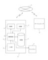
図6は本発明の本実施例の構成を含んだシステム概要図であり、図6から理解されるように、それぞれの点滅型自発光マーカ37の近傍位置には電源としてのバッテリー39、LEDの輝度を増幅させる増幅回路40及び同期信号送信器41からの同期信号を受信する同期信号受信器42が設置されている。
そして、前記同期信号送信器41と同期信号受信器42との信号の送受信によっていずれの取り付け位置にある点滅型自発光マーカ37かが認識できるものとなっている。
FIG. 6 is a system overview diagram including the configuration of this embodiment of the present invention. As can be seen from FIG. 6, a battery 39 as a power source, an amplifier circuit 40 that amplifies the brightness of the LED, and a synchronization signal receiver 42 that receives a synchronization signal from a synchronization signal transmitter 41 are installed in the vicinity of each flashing self-luminous marker 37.
By transmitting and receiving signals between the synchronization signal transmitter 41 and the synchronization signal receiver 42, it is possible to identify the mounting position of the blinking self-luminous marker 37.
1 支保工
2 地山
3 エレクター
4 支保工部材
5 クランプ
6 バスケット
7 吹付ブーム
8 車両本体
9 ブーム
10 仮想マーカ
11 平面マーカ
12 近赤外線カメラ
13 投光体
14 ディスプレイ
18 送信部
19 受信部
20 演算制御部
21 記憶部
22 入力部
23 通信回線網
24 サーバコンピュータ
25 PC
32 支保工建て込み位置計画図形成部
33 支保工建て込み位置読み込み部
34 支保工建て込み位置描画部
35 自発光マーカ
36 吹付ノズル
37 点滅型自発光マーカ
38 サブブーム
39 バッテリー
40 増幅回路
41 同期信号送信器
42 同期信号受信器
43 ベースステーション
44 受光レンズ面
Reference Signs List 1 shoring 2 ground 3
32 Support erection position
Claims (3)
可動するブームに設けられたクランプあるいは吹付ノズルに取り付けられ、異なる点滅周期が与えられて各々個別認識できると共に、各々の取り付け位置が認識できる点滅自発光型の構成を有する通常マーカと、
前記仮想マーカ及び通常マーカからの光を取得する間隔をあけて設置された複数の近赤外線カメラと、
前記複数の近赤外線カメラが取得した前記仮想マーカ及び通常マーカからの光から前記仮想マーカ及び通常マーカの座標位置を算出する演算制御部と、
算出された前記仮想マーカ及び通常マーカの座標位置を保存する記憶部と、
前記演算制御部は前記仮想マーカの取り外し後、前記通常マーカを移動させた後の通常マーカの座標位置から仮想マーカの座標位置を算出する手段を、有する、
ことを特徴とするトンネル施工システム。
At least a pair of booms protruding from both sides in the width direction of the erector in a swingable manner, clamps attached to the tips of the at least a pair of booms, support members that are gripped by the clamps, and at least two virtual markers attached to both ends in the longitudinal direction of the support members and reflecting irradiated near-infrared light;
A normal marker having a flashing self-luminous configuration that is attached to a clamp or a spray nozzle provided on a movable boom and is given a different flashing cycle so that each can be individually recognized and each mounting position can be recognized;
A plurality of near-infrared cameras installed at intervals to acquire light from the virtual markers and the normal markers;
an arithmetic and control unit that calculates coordinate positions of the virtual markers and the normal markers from the light from the virtual markers and the normal markers acquired by the multiple near-infrared cameras;
a storage unit that stores the calculated coordinate positions of the virtual marker and the normal marker;
The arithmetic and control unit has a means for calculating a coordinate position of the virtual marker from a coordinate position of the normal marker after the virtual marker is removed and the normal marker is moved.
A tunnel construction system characterized by:
可動するブームに設けられたクランプあるいは吹付ノズルに取り付けられ、異なる点滅周期が与えられて各々個別認識できると共に、各々の取り付け位置が認識できる点滅自発光型の構成を有する通常マーカと、
前記仮想マーカ及び通常マーカからの光を取得する間隔をあけて設置された複数の近赤外線カメラと、
前記複数の近赤外線カメラが取得した前記仮想マーカ及び通常マーカからの光から前記仮想マーカ及び通常マーカの座標位置を算出する演算制御部と、
算出された前記仮想マーカ及び通常マーカの座標位置を保存する記憶部と、
前記演算制御部は前記仮想マーカの取り外し後、前記通常マーカを移動させた後の通常マーカの座標位置から仮想マーカの座標位置を算出する手段を有し、
前記演算制御部で座標位置が算出された仮想マーカの取り外し後、前記通常マーカを移動させた後の通常マーカの座標位置から仮想マーカの移動した座標位置をリアルタイムに認識出来る、
ことを特徴とするトンネル施工システム。
A pair of booms protruding from both sides of the erector in a swingable manner, clamps attached to the ends of the pair of booms, support members that are gripped by the clamps, and at least two virtual markers attached to both ends of the support members in the longitudinal direction and that reflect irradiated near-infrared light;
A normal marker having a self-luminous flashing configuration that is attached to a clamp or a spray nozzle provided on a movable boom and that is given a different flashing cycle so that each can be individually recognized and each mounting position can be recognized;
A plurality of near-infrared cameras installed at intervals to acquire light from the virtual markers and the normal markers;
an arithmetic and control unit that calculates coordinate positions of the virtual markers and the normal markers from the light from the virtual markers and the normal markers acquired by the multiple near-infrared cameras;
a storage unit that stores the calculated coordinate positions of the virtual marker and the normal marker;
the calculation control unit has a means for calculating a coordinate position of the virtual marker from a coordinate position of the normal marker after the virtual marker is removed and the normal marker is moved,
After removing the virtual marker whose coordinate position has been calculated by the arithmetic control unit, the coordinate position of the virtual marker can be recognized in real time from the coordinate position of the normal marker after the normal marker is moved.
A tunnel construction system characterized by:
ことを特徴とする請求項1または請求項2記載のトンネル施工システム。
The brightness of the flashing self-illuminating normal marker can be increased by an amplifier circuit.
3. A tunnel construction system according to claim 1 or 2.
Priority Applications (1)
| Application Number | Priority Date | Filing Date | Title |
|---|---|---|---|
| JP2021001319A JP7588939B2 (en) | 2021-01-07 | 2021-01-07 | Tunnel Construction System |
Applications Claiming Priority (1)
| Application Number | Priority Date | Filing Date | Title |
|---|---|---|---|
| JP2021001319A JP7588939B2 (en) | 2021-01-07 | 2021-01-07 | Tunnel Construction System |
Publications (2)
| Publication Number | Publication Date |
|---|---|
| JP2022106383A JP2022106383A (en) | 2022-07-20 |
| JP7588939B2 true JP7588939B2 (en) | 2024-11-25 |
Family
ID=82457133
Family Applications (1)
| Application Number | Title | Priority Date | Filing Date |
|---|---|---|---|
| JP2021001319A Active JP7588939B2 (en) | 2021-01-07 | 2021-01-07 | Tunnel Construction System |
Country Status (1)
| Country | Link |
|---|---|
| JP (1) | JP7588939B2 (en) |
Families Citing this family (2)
| Publication number | Priority date | Publication date | Assignee | Title |
|---|---|---|---|---|
| KR20250154637A (en) | 2024-04-19 | 2025-10-29 | 한국철도기술연구원 | Supplementary device and method for position information of unmanned multi copters in GPS dead zones within railroad tunnels |
| KR102809119B1 (en) * | 2024-11-15 | 2025-05-19 | 에이치디씨랩스 주식회사 | Electronic device for detecting defect in interior construction based on artificial intelligence model and method operation thereof |
Citations (7)
| Publication number | Priority date | Publication date | Assignee | Title |
|---|---|---|---|---|
| JP2004078791A (en) | 2002-08-22 | 2004-03-11 | Hitachi Ltd | Personal authentication device and administrative system using the device |
| JP2006030127A (en) | 2004-07-21 | 2006-02-02 | Japan Science & Technology Agency | Camera calibration system and three-dimensional measurement system |
| JP2006057238A (en) | 2004-08-17 | 2006-03-02 | Enzan Kobo:Kk | Drilling positioning control method for rock drill-equipped truck |
| JP2015009008A (en) | 2013-07-01 | 2015-01-19 | 株式会社ディテクト | Golf swing analysis system |
| JP2019173393A (en) | 2018-03-28 | 2019-10-10 | 前田建設工業株式会社 | Steel support work building method and building system |
| JP2020088591A (en) | 2018-11-26 | 2020-06-04 | 国立大学法人 筑波大学 | Video processing system and video processing device |
| JP2020097821A (en) | 2018-12-17 | 2020-06-25 | ドリルマシン株式会社 | Drilling system |
Family Cites Families (4)
| Publication number | Priority date | Publication date | Assignee | Title |
|---|---|---|---|---|
| JPS58168790A (en) * | 1982-03-29 | 1983-10-05 | 星野 謙三 | Drilling method |
| JPS6285581A (en) * | 1985-10-09 | 1987-04-20 | Sharp Corp | Audio signal transmitter using infrared rays |
| JPH112507A (en) * | 1997-06-12 | 1999-01-06 | Mitsubishi Heavy Ind Ltd | Position detecting method for supply segment in tunnel excavator |
| ITUA20161939A1 (en) * | 2016-03-23 | 2017-09-23 | Cp Tech S R L | APPARATUS FOR THE POSITIONING OF A CENTINA OF SUPPORT AND CONSOLIDATION OF AN EXCAVATION |
-
2021
- 2021-01-07 JP JP2021001319A patent/JP7588939B2/en active Active
Patent Citations (7)
| Publication number | Priority date | Publication date | Assignee | Title |
|---|---|---|---|---|
| JP2004078791A (en) | 2002-08-22 | 2004-03-11 | Hitachi Ltd | Personal authentication device and administrative system using the device |
| JP2006030127A (en) | 2004-07-21 | 2006-02-02 | Japan Science & Technology Agency | Camera calibration system and three-dimensional measurement system |
| JP2006057238A (en) | 2004-08-17 | 2006-03-02 | Enzan Kobo:Kk | Drilling positioning control method for rock drill-equipped truck |
| JP2015009008A (en) | 2013-07-01 | 2015-01-19 | 株式会社ディテクト | Golf swing analysis system |
| JP2019173393A (en) | 2018-03-28 | 2019-10-10 | 前田建設工業株式会社 | Steel support work building method and building system |
| JP2020088591A (en) | 2018-11-26 | 2020-06-04 | 国立大学法人 筑波大学 | Video processing system and video processing device |
| JP2020097821A (en) | 2018-12-17 | 2020-06-25 | ドリルマシン株式会社 | Drilling system |
Also Published As
| Publication number | Publication date |
|---|---|
| JP2022106383A (en) | 2022-07-20 |
Similar Documents
| Publication | Publication Date | Title |
|---|---|---|
| US11408728B2 (en) | Registration of three-dimensional coordinates measured on interior and exterior portions of an object | |
| JP6746250B2 (en) | Drilling system | |
| US20180003498A1 (en) | Visual positioning system and method based on high reflective infrared identification | |
| JP7588939B2 (en) | Tunnel Construction System | |
| CN110736446B (en) | Pose identification system and method for cantilever type heading machine | |
| CN101451836B (en) | Surveying system | |
| US20160343125A1 (en) | Method of Performing and Monitoring a Processing Step on a Workpiece | |
| JP7278022B2 (en) | Rock bolt drilling system using self-luminous markers | |
| CN114838668B (en) | Tunnel displacement monitoring method and system | |
| JP2005043088A (en) | Survey guidance device | |
| JP2001285681A (en) | Calibration system, target device, and calibration method | |
| CN103635777B (en) | For the structure measurement unit at the edge and corner of following the trail of, measure and mark adjacently situated surfaces | |
| JP2006031642A (en) | Self-position specification method of mobile object | |
| CN112097637B (en) | Measuring device | |
| JP2021173727A (en) | Work management system, work management method, and work management program therefor | |
| CN214426656U (en) | Pipeline inner wall detection system | |
| JP2019173393A (en) | Steel support work building method and building system | |
| CN2601390Y (en) | Handpiece attitude laser measurer for miniature push bench | |
| CN112265912A (en) | Integrated operation system and method of lorry-mounted crane | |
| JP2022024410A (en) | Construction member measurement method and measurement system for that | |
| JP6252830B2 (en) | Telemetry system | |
| JPH0545117A (en) | Optical 3D position measurement method | |
| CN118023797A (en) | Automatic welding system and method based on indication guidance | |
| KR102488176B1 (en) | Equipment for Leveling | |
| US11935292B2 (en) | Method and a system for analyzing a scene, room or venue |
Legal Events
| Date | Code | Title | Description |
|---|---|---|---|
| A521 | Request for written amendment filed |
Free format text: JAPANESE INTERMEDIATE CODE: A523 Effective date: 20210119 |
|
| A621 | Written request for application examination |
Free format text: JAPANESE INTERMEDIATE CODE: A621 Effective date: 20231204 |
|
| A977 | Report on retrieval |
Free format text: JAPANESE INTERMEDIATE CODE: A971007 Effective date: 20240621 |
|
| A131 | Notification of reasons for refusal |
Free format text: JAPANESE INTERMEDIATE CODE: A131 Effective date: 20240625 |
|
| A601 | Written request for extension of time |
Free format text: JAPANESE INTERMEDIATE CODE: A601 Effective date: 20240821 |
|
| A521 | Request for written amendment filed |
Free format text: JAPANESE INTERMEDIATE CODE: A523 Effective date: 20240902 |
|
| TRDD | Decision of grant or rejection written | ||
| A01 | Written decision to grant a patent or to grant a registration (utility model) |
Free format text: JAPANESE INTERMEDIATE CODE: A01 Effective date: 20241112 |
|
| A61 | First payment of annual fees (during grant procedure) |
Free format text: JAPANESE INTERMEDIATE CODE: A61 Effective date: 20241112 |
|
| R150 | Certificate of patent or registration of utility model |
Ref document number: 7588939 Country of ref document: JP Free format text: JAPANESE INTERMEDIATE CODE: R150 |