JP7588024B2 - Shock absorbing components for vehicle frames - Google Patents
Shock absorbing components for vehicle frames Download PDFInfo
- Publication number
- JP7588024B2 JP7588024B2 JP2021064863A JP2021064863A JP7588024B2 JP 7588024 B2 JP7588024 B2 JP 7588024B2 JP 2021064863 A JP2021064863 A JP 2021064863A JP 2021064863 A JP2021064863 A JP 2021064863A JP 7588024 B2 JP7588024 B2 JP 7588024B2
- Authority
- JP
- Japan
- Prior art keywords
- vehicle body
- section
- closed cross
- absorbing member
- section members
- Prior art date
- Legal status (The legal status is an assumption and is not a legal conclusion. Google has not performed a legal analysis and makes no representation as to the accuracy of the status listed.)
- Active
Links
- 230000035939 shock Effects 0.000 title claims description 53
- 239000011324 bead Substances 0.000 claims description 21
- 210000001503 joint Anatomy 0.000 claims description 15
- 238000003466 welding Methods 0.000 claims description 14
- 239000000463 material Substances 0.000 description 6
- 229910000831 Steel Inorganic materials 0.000 description 4
- 238000010586 diagram Methods 0.000 description 4
- 238000005192 partition Methods 0.000 description 4
- 239000010959 steel Substances 0.000 description 4
- 230000000694 effects Effects 0.000 description 3
- 239000000725 suspension Substances 0.000 description 3
- 239000000446 fuel Substances 0.000 description 2
- 230000002452 interceptive effect Effects 0.000 description 2
- 238000004519 manufacturing process Methods 0.000 description 2
- 239000013585 weight reducing agent Substances 0.000 description 2
- 230000009471 action Effects 0.000 description 1
- 230000004075 alteration Effects 0.000 description 1
- 230000008859 change Effects 0.000 description 1
- 230000006866 deterioration Effects 0.000 description 1
- 230000013011 mating Effects 0.000 description 1
- 230000004048 modification Effects 0.000 description 1
- 238000012986 modification Methods 0.000 description 1
- 230000003014 reinforcing effect Effects 0.000 description 1
Images


Landscapes
- Body Structure For Vehicles (AREA)
Description
本発明は、車体フレームの先端部に衝突時の衝撃力を吸収するために設けられる車体フレーム用の衝撃吸収部材に関する。 The present invention relates to an impact absorbing member for a vehicle body frame that is installed at the tip of the vehicle body frame to absorb the impact force during a collision.
図1に示すように、トラック、バス、RV等の車両の車体フレーム1として、車幅方向に間隔を隔てて車長方向に延出された一対のサイドメンバ2と、これらサイドメンバ2の間に車長方向に間隔を隔てて架け渡された複数のクロスメンバ3とを備えたラダーフレームが知られている。サイドメンバ2の先端には、車体フレーム1用の衝撃吸収部材(図1の太線部分)4が備えられており、衝突時にバンパー5に衝撃が加わったとき、衝撃吸収部材4が軸圧壊することで衝撃力を吸収するようになっている。
As shown in Figure 1, a ladder frame is known as a
図2(a)、図2(b)に示すように、従来の衝撃吸収部材4として、車体の前後方向に延出されたコ字断面材5a、5bを一組向き合わせて最中状に溶接してなる四角筒体6が知られている。なお、7は溶接ビードである。斯様な筒状の衝撃吸収部材4は、軸方向(車体の前後方向)から荷重を受けたとき、軸方向に平行な稜線8の数が増えるほど耐荷重が上がる。しかし、四角筒体6からなる衝撃吸収部材4は、内部の稜線8の数が4本しかなく、耐荷重を増大させることが困難であった。
As shown in Figures 2(a) and 2(b), a conventional
耐荷重を増大できる衝撃吸収部材4として、四角筒体ではなく多角形(五角形以上)の筒体とし、内部における軸方向に平行な稜線の数を4以上としたものが知られている(特許文献1、2参照)。しかし、衝撃吸収部材4は、図1に示すように、車体フレーム1の一部を兼ねるため、様々な部品(車体ボディーやサスペンションを支持するブラケット等)を衝撃吸収部材4の外面に取り付ける場合があり、衝撃吸収部材4が多角形の筒体であると、それらの部品を衝撃吸収部材4の外面に取り付けることが困難となり得る。すなわち、衝撃吸収部材4の外面に他部品を取り付けることを考慮すると、現在、四角筒体6である衝撃吸収部材4を多角形化(五角形以上)することは、相手部品規格等の制約を受けるため、困難な場合が多い。
As a
別の衝撃吸収部材4として、四角筒体の内部に仕切板を挿入し、仕切板によって耐荷重を増大させるようにしたものが知られている(特許文献3参照)。しかし、四角筒体の内部に仕切板を挿入して組み付けることは困難であり、生産性に課題がある。また、仕切板が内部に収納されているため、仕切板の分の重量がアップし、車両(トラック、バス、RV等)の燃費悪化を招く。
Another type of
また、筒状に形成された衝撃吸収部材4の外面に孔や凹部等の脆弱部を形成し、軸方向(車体の前後方向)から衝撃を受けたときの変形モードを制御することも通常行われている(特許文献4参照)。しかし、衝撃吸収部材4の外面に脆弱部として孔や凹部等を設けると、衝撃吸収部材4の外面に、上述のように様々な部品(車体ボディーやサスペンションを支持するブラケット等)を取り付ける際、孔や凹部などから成る脆弱部によって部品の取り付けが妨げられることがある。
It is also common to form weak parts such as holes and recesses on the outer surface of the cylindrically formed
以上の事情を考慮して創案された本発明の目的は、車体の前後方向から衝撃を受けて軸圧壊する際の耐荷重を増大でき、外面に部品を取り付ける際の自由度を確保でき、生産性が高く、軽量で、軸圧壊するときの変形モードを制御できる車体フレーム用の衝撃吸収部材を提供することにある。 The object of the present invention, which was devised in consideration of the above circumstances, is to provide an impact absorbing member for a vehicle frame that can increase the load resistance when the vehicle body is subjected to an impact from the front or rear direction and collapses axially, ensures freedom when attaching parts to the outer surface, is highly productive, is lightweight, and can control the deformation mode when collapsing axially.
上記目的を達成すべく創案された本発明によれば、車体の前後方向に延びる閉断面部材が二本車幅方向に隣接配置され、双方の閉断面部材の側面が付き合わせられた状態で、閉断面部材同士が溶接されて一体化された車体フレーム用の衝撃吸収部材であって、閉断面部材が、車体の前後方向に延びる一組のコ字断面材を向き合わせて車体前後方向に沿って連続溶接された溶接ビードを有する最中型閉断面部材であり、最中型閉断面部材が二本車幅方向に隣接配置されて側面同士が付き合わせられた状態で車体前後方向に沿って連続溶接された溶接ビードによって一体化されており、最中型閉断面部材同士が溶接された後には外から見えなくなる最中型閉断面部材の側面の突き合わせ部に、車体の前後方向から荷重を受けた際に変形の起点となる孔および凹部の少なくとも一方から成る脆弱部が形成されている、ことを特徴とする車体フレーム用の衝撃吸収部材が提供される。 According to the present invention, which has been devised to achieve the above-mentioned object, there is provided an impact absorbing member for a vehicle body frame, in which two closed cross-section members extending in the fore-and-aft direction of the vehicle body are arranged adjacent to each other in the vehicle width direction, and the closed cross-section members are welded together with their side surfaces butted together to form an integrated shock absorbing member, wherein the closed cross-section members are mid-size closed cross-section members having a weld bead formed by facing a pair of U-shaped cross-section members extending in the fore-and-aft direction of the vehicle body and continuously welding them along the fore-and-aft direction of the vehicle body, and the two mid-size closed cross-section members are arranged adjacent to each other in the vehicle width direction and integrated with their side surfaces butted together by a weld bead formed continuously along the fore-and-aft direction of the vehicle body, and a weak portion consisting of at least one of a hole and a recess which becomes a starting point of deformation when a load is applied from the fore-and-aft direction of the vehicle body is formed at the butt joint of the side of the mid-size closed cross-section member, which cannot be seen from the outside after the mid-size closed cross-section members are welded together.
本発明に係る車体フレーム用の衝撃吸収部材においては、最中型閉断面部材が、大型のコ字断面材とその内方に嵌るサイズの小型のコ字断面材とを向き合わせて車体前後方向に沿って連続隅肉溶接された溶接ビードを有し、かかる最中型閉断面部材が、二本、小型のコ字断面材同士を接するように車幅方向に隣接配置されて車体前後方向に沿って連続溶接された溶接ビードによって一体化されていてもよい。 In the impact absorbing member for a vehicle body frame of the present invention, a mid-sized closed cross-section member has a large U-shaped cross-section member and a small U-shaped cross-section member of a size that fits inside it, facing each other with a weld bead formed by continuous fillet welding along the fore-and-aft direction of the vehicle body , and two such mid-sized closed cross-section members may be arranged adjacent to each other in the vehicle width direction so that the small U-shaped cross-section members are in contact with each other and are integrated by a weld bead formed continuously along the fore-and-aft direction of the vehicle body.
本発明に係る車体フレーム用の衝撃吸収部材においては、脆弱部が、閉断面部材同士の側面の突き合わせ部の夫々に、車体前後方向の同じ位置に形成されていてもよい。 In the shock absorbing member for a vehicle body frame according to the present invention, the weak parts may be formed at the same positions in the fore-and-aft direction of the vehicle body at each of the butt joints on the side surfaces of the closed cross-section members.
本発明に係る車体フレーム用の衝撃吸収部材においては、脆弱部が、閉断面部材同士の側面の突き合わせ部の夫々に、車体前後方向に位置をずらして形成されていてもよい。 In the shock absorbing member for a vehicle body frame according to the present invention, the weak parts may be formed at each of the butt joints on the side surfaces of the closed cross-section members, with the weak parts being shifted in position in the fore-and-aft direction of the vehicle body.
本発明に係る車体フレーム用の衝撃吸収部材によれば、次のような効果を発揮できる。
(1)車体の前後方向に延びる衝撃吸収用の閉断面部材が二本車幅方向に隣接配置され、双方の閉断面部材の側面が付き合わせられた状態で、閉断面部材同士が溶接されて一体化されているので、内部における軸方向に平行な稜線の数が、閉断面部材が一本の場合の二倍となり、車体の前後方向から衝撃を受けて軸圧壊する際の耐荷重が増大する。
(2)閉断面部材同士が溶接された後には外から見えなくなる閉断面部材の側面の突き合わせ部に、車体の前後方向から荷重を受けた際に変形の起点となる孔および凹部の少なくとも一方から成る脆弱部が形成されているので、衝撃吸収部材の外面に部品を取り付ける際、脆弱部を構成する孔や凹部によって部品の取り付けが妨げられる事態を回避でき、部品の取り付けの自由度を確保できる。
(3)孔や凹部などの脆弱部が側面に形成された閉断面部材を、二本、側面同士を付き合わせて溶接した構造となっているので、孔や凹部などの脆弱部が外面から見えない衝撃吸収部材を容易に製造でき、生産性が高い。
(4)脆弱部を構成する孔が軽量孔となり、脆弱部を構成する凹部が肉抜き凹部となるので、軽量化を推進できる。
(5)閉断面部材同士の突き合わせ部に形成された脆弱部(孔、凹部)の車体前後方向に沿った位置や大きさを適宜変更することで、軸圧壊するときの変形モードを制御できる。
(6)以上要するに、本発明に係る車体フレーム用の衝撃吸収部材によれば、車体の前後方向から衝撃を受けて軸圧壊する際の耐荷重を増大でき、外面に部品を取り付ける際の自由度を確保でき、生産性が高く、軽量で、軸圧壊するときの変形モードを制御できる。
The shock absorbing member for a vehicle body frame according to the present invention can provide the following effects.
(1) Two closed cross-section members for absorbing impact, extending in the fore-and-aft direction of the vehicle body, are arranged adjacent to each other in the vehicle width direction, and with the sides of the two closed cross-section members butted together, the closed cross-section members are welded together to form an integrated body. As a result, the number of ridges parallel to the axial direction inside the body is twice as many as in the case of a single closed cross-section member, thereby increasing the load-bearing capacity when the body is subjected to axial collapse upon impact from the fore-and-aft direction of the vehicle body.
(2) A weak portion consisting of at least one of a hole and a recess, which becomes the starting point of deformation when a load is applied from the fore-aft direction of the vehicle body, is formed at the butt joint of the side of the closed cross-section member, which becomes invisible from the outside after the closed cross-section members are welded together. Therefore, when attaching parts to the outer surface of the impact absorbing member, it is possible to avoid a situation in which the attachment of the parts is hindered by the holes or recesses that constitute the weak portion, and it is possible to ensure freedom in attaching the parts.
(3) Since the structure is formed by welding two closed cross-section components, each of which has a weak portion such as a hole or a recess formed on its side, together with its side surface butted against each other, it is possible to easily manufacture an impact absorbing component in which the weak portion such as the hole or recess is not visible from the outside, resulting in high productivity.
(4) The holes constituting the fragile portions are lightening holes, and the recesses constituting the fragile portions are lightening recesses, which contributes to weight reduction.
(5) By appropriately changing the position and size, along the fore-and-aft direction of the vehicle body, of the weak portions (holes, recesses) formed at the butt joints between the closed cross-section members, the deformation mode during axial collapse can be controlled.
(6) In summary, the shock absorbing member for a vehicle body frame of the present invention can increase the load capacity when the vehicle body receives an impact from the front or rear direction and undergoes axial collapse, ensures freedom in attaching parts to the outer surface, is highly productive, is lightweight, and makes it possible to control the deformation mode during axial collapse.
以下に添付図面を参照しながら、本発明の好適な実施形態について詳細に説明する。係る実施形態に示す寸法、材料、その他具体的な数値等は、発明の理解を容易にするための例示に過ぎず、特に断る場合を除き、本発明を限定するものではない。なお、本明細書および図面において、実質的に同一の機能、構成を有する要素については、同一の符号を付することにより重複説明を省略し、また本発明に直接関係のない要素は図示を省略する。 The preferred embodiment of the present invention will be described in detail below with reference to the attached drawings. The dimensions, materials, and other specific values shown in the embodiment are merely examples to facilitate understanding of the invention, and do not limit the present invention unless otherwise specified. In this specification and drawings, elements having substantially the same functions and configurations are given the same reference numerals to avoid duplicated explanations, and elements not directly related to the present invention are not illustrated.
(車体フレーム1用の衝撃吸収部材9)
図3、図4に示す本発明の一実施形態に係る車体フレーム1用の衝撃吸収部材9は、図1に示すように、車体フレーム1(ラダーフレーム)のサイドメンバ2の先端に取り付けられ、衝突時にバンパー5に衝撃が加わったとき、衝撃吸収部材9が軸圧壊することで衝撃力を吸収するものである。
(Impact absorbing
An
図3、図4に示すように、本実施形態に係る衝撃吸収部材9は、車体の前後方向に延びる衝撃吸収用の閉断面部材10が二本車幅方向に隣接配置され、これら閉断面部材10の側面10aが付き合わせられた状態で、閉断面部材10同士が溶接されて一体化された構造となっている。また、この衝撃吸収部材9は、閉断面部材10同士が溶接された後には外から見えなくなる閉断面部材10の側面10aの突き合わせ部10bに、車体の前後方向(軸方向)から荷重を受けた際に変形の起点となる孔11および凹部12の少なくとも一方から成る脆弱部13が形成されている。以下、各構成要素を説明する。
As shown in Figures 3 and 4, the
(閉断面部材10)
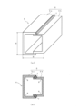
図3(a)、図3(b)に示すように、閉断面部材10は、本実施形態においては、車体の前後方向に延びる一組のコ字断面材14、15を向き合わせて溶接してなる最中型閉断面部材10xから構成されている。コ字断面材14、15は、大型のコ字断面材14とその内方に嵌まるサイズの小型のコ字断面台15とからなり、これらが向き合わせられて最中型に組み合わせられ、組み合わせ部が車体前後方向に沿って溶接(隅肉溶接)されて一体化されている。なお、16は車体の前後方向に沿った溶接ビードである。
(Closed cross-section member 10)
As shown in Figures 3(a) and 3(b), in this embodiment, the closed
図3(a)、図3(b)に示すように、大型のコ字断面材14は、車体前後方向に延びる縦壁からなるウェブ14aと、ウェブ14aの上端から車幅方向に延出された上部フランジ14bと、ウェブ14aの下端から車幅方向に延出された下部フランジ14cとかなり、小型のコ字断面材15も、同様に、ウェブ15aと、上部フランジ15bと、下部フランジ15cとからなる。上部フランジ14bに上部フランジ15bが重ねられ、下部フランジ14cに下部フランジ15cが重ねられ、これらが溶接(溶接ビード16)されることで、大型のコ字断面材14と小型のコ字断面材15とから最中型閉断面部材10xが構成されている。
As shown in Figures 3(a) and 3(b), the large U-shaped
(脆弱部13)
図3(a)、図3(b)に示すように、小型のコ字断面材15のウェブ15aには、孔11および凹部12から成る脆弱部13が形成されている。本実施形態においては、脆弱部13として、孔(貫通孔)11および凹部(窪み部)12が形成されているが、何れか一方のみであってもよい。また、孔11や凹部12等の脆弱部13は、車体前後方向に間隔を隔てて配設されることに加え、上下方向に間隔を隔てて並設されていても構わない。なお、凹部12は四角ではなく円形の窪み部でもよい。
(Weakened portion 13)
As shown in Figures 3(a) and 3(b), a
図3(a)、図3(b)に示す脆弱部13は、図4(a)、図4(b)、図4(c)に示すように、小型のコ字断面材15のウェブ15a同士が付き合わせられた状態で溶接(突合せ溶接)されることで、外部から見えなくなる。なお、17は車体の前後方向に沿った溶接ビードである。すなわち、小型のコ字断面材15のウェブ15aに脆弱部13が形成された一対の最中型閉断面部材10xが、そのウェブ15a同士を付き合わせて溶接(溶接ビード17)されることで衝撃吸収部材9が構成されており、これにより脆弱部13が衝撃吸収部材9の外観から見えなくなっている。
The
図4(a)、図4(b)、図4(c)に示すように、脆弱部13は、本実施形態においては、閉断面部材10同士の側面10aの突き合わせ部10b(小型のコ字断面材15のウェブ15a)の夫々に、車体前後方向の同じ位置に形成されている。これにより、衝突時、軸圧壊の起点を明確に設定できる。但し、脆弱部13が、閉断面部材10同士の側面10aの突き合わせ部10bの夫々に、車体前後方向に位置をずらして形成されていてもよい。これにより、軸圧壊の起点が車体前後方向に分散される。
As shown in Figures 4(a), 4(b), and 4(c), in this embodiment, the
図4(a)に示すように、本実施形態に係る車体フレーム1用の衝撃吸収部材9の高さH1、幅B1を、図2(a)に示す従来の車体フレーム1用の衝撃吸収部材4の高さH、幅Bと比べると、H1=H、B1=Bとなっている。よって、本実施形態に係る衝撃吸収部材9は、図1に示す車体フレーム1のサイドメンバ2の先端に、従来の衝撃吸収部材4に代えて装着された場合、周辺部品と干渉することはなく、適切に装着できる。
As shown in FIG. 4(a), when the height H1 and width B1 of the
(作用・効果)
本実施形態に係る車体フレーム1用の衝撃吸収部材9によれば、図4(b)に示すように、車体の前後方向に延びる衝撃吸収用の閉断面部材10が二本車幅方向に隣接配置され、これら閉断面部材10の側面10aが付き合わせられた状態で閉断面部材10同士が溶接されて一体化されているので、内部における軸方向に平行な稜線8の数(8本)が、図2(b)に示す従来例の閉断面部材(四角筒4)が一本の場合の稜線8の数(4本)の二倍となり、車体の前後方向から衝撃を受けて軸圧壊する際の耐荷重が増大する。よって、従来よりも大きな衝撃荷重を適切に吸収できる。
(Action and Effects)
According to the
また、本実施形態に係る衝撃吸収部材9においては、図4(a)に示すように、閉断面部材10に一般的な角パイプ材ではなく、一組のコ字断面材14、15を向き合わせて溶接してなる最中型閉断面部材10xを用いている。このため、図4(b)、図4(c)に示すように、車体の前後方向に沿った溶接ビード16、17の数(6本)が図2(b)に示す従来例の溶接ビード7の数(2本)の三倍になり、溶接ビード16、17が母材であるコ字断面材14、15よりも強度が高い強度部材として機能するため、車体の前後方向から衝撃を受けて軸圧壊する際の耐荷重が増大する。よって、従来よりも大きな衝撃荷重を適切に吸収できる
In addition, in the
図4(a)に示すように、閉断面部材10同士が溶接された後には外から見えなくなる閉断面部材10の側面10aの突き合わせ部10bに、車体の前後方向(軸方向)から荷重を受けた際に変形の起点となる孔11および凹部12から成る脆弱部13が形成されているので、衝撃吸収部材9の外面9aに部品を取り付ける際、脆弱部13を構成する孔11や凹部12によって部品の取り付けが妨げられる事態を回避でき、部品の取り付けの自由度を確保できる。
As shown in FIG. 4(a), a
すなわち、衝撃吸収部材9は、図1に示すように、車体フレーム1の一部を兼ねるため、様々な部品(車体ボディーやサスペンションを支持するブラケット等)を衝撃吸収部材9の外面に取り付ける場合がある。ここで、衝撃吸収部材9の外面9aに脆弱部13を成す孔11や凹部12が形成されていると、それらが部品を取り付けるときの妨げとなる。本実施形態に係る衝撃吸収部材9によれば、図4(a)に示すように、衝撃吸収部材9の外面9aに、脆弱部13を構成する孔11や凹部12等の段差が無いフラットな平面を確保できるので、そこに様々な部品を適切に取り付けることができる。
In other words, as shown in FIG. 1, the
本実施形態に係る衝撃吸収部材9は、図3(a)に示すように、側面10a(小型のコ字断面材15のウェブ15a)に孔11や凹部12などの脆弱部13が形成された二本の閉断面部材10(最中型閉断面部材10x)の側面10a同士を付き合わせて溶接した構造となっているので、孔11や凹部12などの脆弱部13が外面から見えない衝撃吸収部材9を容易に製造でき、生産性が高い。すなわち、本実施形態に係る衝撃吸収部材9は、予め脆弱部13が形成されている閉断面部材10同士を脆弱部13が隠れるように溶接して構成されているので、内部に脆弱部13を有する衝撃吸収部材9を容易に製造できる。
As shown in FIG. 3(a), the
図4(a)に示す閉断面部材10同士の側面10aの突き合わせ部10bに形成された脆弱部13(孔11、凹部12)の車体前後方向に沿った位置や大きさを適宜変更することで、軸圧壊するときの変形モードを制御できる。例えば、本実施形態のように、脆弱部13を双方の閉断面部材10の側面10aの突き合わせ部10bの夫々に車体前後方向の同じ位置に形成することで、その部分の強度が低下し、軸圧壊の起点を明確に設定できる。また、脆弱部13を双方の閉断面部材10の側面10aの突き合わせ部10bの夫々に車体前後方向に位置をずらして形成することで、軸圧壊の起点が車体前後方向に分散され、突き合わせ部10bの長手方向に沿って全体的に軸圧壊させることができる。
The deformation mode during axial collapse can be controlled by appropriately changing the position and size along the vehicle front-rear direction of the weak parts 13 (
図4(b)に示すように、軸圧壊の起点となる脆弱部13を構成する孔11が軽量孔となり、図4(c)に示すように、脆弱部13を構成する凹部12が肉抜き凹部となるので、軽量化を推進できる。よって、車両(トラック、バス、RV等)の燃費を向上できる。
As shown in FIG. 4(b), the
以上要するに、本実施形態に係る車体フレーム1用の衝撃吸収部材9によれば、車体の前後方向から衝撃を受けて軸圧壊する際の耐荷重を増大でき、外面に部品を取り付ける際の自由度を確保でき、生産性が高く、軽量で、軸圧壊するときの変形モードを制御できる。
In summary, the
(変形実施形態)
図5、図6を用いて、本発明の変形実施形態に係る車体フレーム1用の衝撃吸収部材9aを説明する。この変形実施形態に係る衝撃吸収部材9aは、閉断面部材10の構造が上述した図3、図4に示す衝撃吸収部材9の閉断面部材10(最中型閉断面部材10x)と異なっており、その他は前実施形態と同様の構成となっている。よって、相違点である閉断面部材10の構造の変更について説明し、その他の同様の構成については説明を省略する。
(Modified embodiment)
An impact absorbing member 9a for a
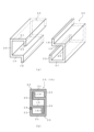
変形実施形態に係る閉断面部材10は、図5(a)に示すように、第1縦壁18、第1横壁19、第2縦壁20、第2横壁21、第3縦壁22が夫々直角に連なった特殊形状の形鋼23(引抜き材等)を二本、180度向きを変えて用意し、これらの形鋼23を図5(b)に示すように組み合わせて溶接することで構成され、略目の字型の閉断面部材(以下、目の字型閉断面部材10y)となっている。なお、24は車体の前後方向に沿った溶接ビードである。
As shown in Fig. 5(a), the
図5(b)に示す目の字型閉断面部材10yは、図5(a)に示すように、長手方向に沿った軸に対して断面が点対称(180度対称)な二本の特殊形状の形鋼23を組み合わせた構造なので、図3(b)に示す大型のコ字断面材14と小型のコ字断面材15とを組み合わせた構造である前実施形態の最中型閉断面部材10xと比べ、部品の共用化を図ることができ、低コストに製造できる。また、図5(b)に示すように、二本の特殊形状の形鋼23の第1横壁19は、目の字型閉断面部材10yの内部において上下二段の補強壁となるので、剛性向上に寄与する。
The eye-shaped closed cross-section member 10y shown in FIG. 5(b) is a structure in which two specially shaped
図6(a)に示すように、目の字型閉断面部材10yの側面10aは、第2縦壁20と第3縦壁22とから構成されており、第2縦壁20には、孔11および凹部12から成る脆弱部13が形成されている。本実施形態においては、第2縦壁20には、脆弱部13として孔11(貫通孔)および凹部12(窪み部)が形成されているが、何れか一方のみであってもよい。また、脆弱部13を構成する孔11や凹部12等は、車体前後方向に間隔を隔てて配設されることに加え、上下方向に間隔を隔てて並設されていてもよく、第3縦壁22に形成されていても構わない。なお、凹部12は四角ではなく円形の窪み部でもよい。
As shown in FIG. 6(a), the side surface 10a of the eye-shaped closed cross-section member 10y is composed of a second
図6(a)に示す脆弱部13は、図6(b)に示すように、二本の目の字型閉断面部材10yの側面10aが付き合わせられた状態で、目の字型閉断面部材10y同士が溶接されて一体化されることで、外部から見えなくなる。なお、25は車体の前後方向に沿った溶接ビードである。すなわち、側面10aを構成する第2縦壁20に脆弱部13が形成された一対の目の字型閉断面部材10yが、側面10a同士を付き合わせて溶接されることで衝撃吸収部材9aが構成されており、これにより突き合せ部10bに形成された脆弱部13が衝撃吸収部材9aの外観から見えなくなっている。
The
図6(a)に示すように、脆弱部13は、目の字型閉断面部材10y同士の側面10aの突き合わせ部10b(第2縦壁20)の夫々に、車体前後方向の同じ位置に形成されている。これにより、衝突時、軸圧壊の起点を明確に設定できる。但し、脆弱部13が、目の字型閉断面部材10y同士の側面10aの突き合わせ部10bの夫々に、車体前後方向に位置をずらして形成されていてもよい。これにより、軸圧壊の起点が車体前後方向に分散される。
As shown in FIG. 6(a), the
図6(b)に示すように、変形施形態に係る車体フレーム1用の衝撃吸収部材9aの高さH2、幅B2を、図2(a)に示す従来の車体フレーム1用の衝撃吸収部材4の高さH、幅Bと比べると、H2=H、B2=Bとなっている。よって、変形実施形態に係る衝撃吸収部材9aは、図1に示す車体フレーム1のサイドメンバ2の先端に、従来の衝撃吸収部材4に代えて装着された場合、周辺部品と干渉することはなく、適切に装着できる。
As shown in FIG. 6(b), when the height H2 and width B2 of the shock absorbing member 9a for the
その他、この変形実施形態に係るの車体フレーム1用の衝撃吸収部材9a基本的な作用効果は、前実施形態に係る車体フレーム1用の衝撃吸収部材9と同様であるので、説明を省略する。
Otherwise, the basic effects of the shock absorbing member 9a for the
以上、添付図面を参照しつつ本発明の好適な実施形態について説明したが、本発明は上述した実施形態に限定されないことは勿論であり、特許請求の範囲に記載された範疇における各種の変更例または修正例についても、本発明の技術的範囲に属することは言うまでもない。 The above describes a preferred embodiment of the present invention with reference to the attached drawings, but it goes without saying that the present invention is not limited to the above-mentioned embodiment, and various modifications and alterations within the scope of the claims also fall within the technical scope of the present invention.
例えば、本発明に係る衝撃吸収部材9、9aが装着される車体フレーム1は、図1に示すようなラダーフレームに限られるものではなく、モノコックボディ(モノコックフレーム)であってもよい。その場合、モノコックボディの前部に本発明に係る衝撃吸収部材9、9aが装着される。また、閉断面部材10は、最中型閉断面部材10xや目の字型閉断面部材10yの他、角パイプでも構わない。
For example, the
本発明は、車体フレーム1の先端部に衝突時の衝撃力を吸収するために設けられる車体フレーム1用の衝撃吸収部材9、9aに利用できる。
The present invention can be used for
1 車体フレーム
9 衝撃吸収部材
9a 衝撃吸収部材
10 閉断面部材
10x 最中型閉断面部材
10y 目の字型閉断面部材
10a 側面
10b 突き合わせ部
11 孔
12 凹部
13 脆弱部
14 コ字断面材
15 コ字断面材
16 溶接ビード
17 溶接ビード
14 U-shaped cross-section material
15 U-shaped cross-section material
16 Weld bead
17 Weld bead
Claims (4)
前記閉断面部材が、車体の前後方向に延びる一組のコ字断面材を向き合わせて車体前後方向に沿って連続溶接された溶接ビードを有する最中型閉断面部材であり、該最中型閉断面部材が二本車幅方向に隣接配置されて側面同士が付き合わせられた状態で車体前後方向に沿って連続溶接された溶接ビードによって一体化されており、
前記最中型閉断面部材同士が溶接された後には外から見えなくなる前記最中型閉断面部材の側面の突き合わせ部に、車体の前後方向から荷重を受けた際に変形の起点となる孔および凹部の少なくとも一方から成る脆弱部が形成されている、ことを特徴とする車体フレーム用の衝撃吸収部材。 An impact absorbing member for a vehicle body frame, comprising two closed cross-section members extending in a front-rear direction of a vehicle body, disposed adjacent to each other in a vehicle width direction, and the closed cross-section members are welded together and integrated in a state in which side surfaces of the two closed cross-section members are butted together,
the closed cross-section member is a mid-length closed cross-section member having a weld bead formed by continuously welding a pair of U-shaped cross-section members extending in the longitudinal direction of the vehicle body facing each other along the longitudinal direction of the vehicle body, and the two mid-length closed cross-section members are adjacently disposed in the vehicle width direction and are integrated with each other by a weld bead formed by continuously welding the weld bead along the longitudinal direction of the vehicle body with their side surfaces butted together,
an impact absorbing member for a vehicle body frame, characterized in that a weak portion consisting of at least one of a hole and a recess, which serves as a starting point of deformation when a load is applied from the fore-and-aft direction of the vehicle body, is formed at the butt joint of the side of the intermediate closed section member, which will not be visible from the outside after the intermediate closed section members are welded together.
かかる最中型閉断面部材が、二本、前記小型のコ字断面材同士を接するように車幅方向に隣接配置されて車体前後方向に沿って連続溶接された溶接ビードによって一体化されている、ことを特徴とする請求項1に記載の車体フレーム用の衝撃吸収部材。 the intermediate closed cross-section member has a weld bead formed by continuously fillet welding a large U-shaped cross-section member and a small U-shaped cross-section member of a size that fits inside the large U- shaped cross-section member in a facing relationship along the front-rear direction of the vehicle body ,
2. An impact absorbing member for a vehicle frame as described in claim 1, characterized in that two such mid-sized closed cross-section members are arranged adjacent to each other in the vehicle width direction so that the small U-shaped cross-section members are in contact with each other and are integrated by a weld bead that is continuously welded along the fore-and-aft direction of the vehicle body.
Priority Applications (1)
| Application Number | Priority Date | Filing Date | Title |
|---|---|---|---|
| JP2021064863A JP7588024B2 (en) | 2021-04-06 | 2021-04-06 | Shock absorbing components for vehicle frames |
Applications Claiming Priority (1)
| Application Number | Priority Date | Filing Date | Title |
|---|---|---|---|
| JP2021064863A JP7588024B2 (en) | 2021-04-06 | 2021-04-06 | Shock absorbing components for vehicle frames |
Publications (2)
| Publication Number | Publication Date |
|---|---|
| JP2022160231A JP2022160231A (en) | 2022-10-19 |
| JP7588024B2 true JP7588024B2 (en) | 2024-11-21 |
Family
ID=83657782
Family Applications (1)
| Application Number | Title | Priority Date | Filing Date |
|---|---|---|---|
| JP2021064863A Active JP7588024B2 (en) | 2021-04-06 | 2021-04-06 | Shock absorbing components for vehicle frames |
Country Status (1)
| Country | Link |
|---|---|
| JP (1) | JP7588024B2 (en) |
Citations (2)
| Publication number | Priority date | Publication date | Assignee | Title |
|---|---|---|---|---|
| WO2012120967A1 (en) | 2011-03-10 | 2012-09-13 | 本田技研工業株式会社 | Automobile chassis frame structure |
| JP2019507057A (en) | 2016-02-09 | 2019-03-14 | ゴードン・マレー・デザイン・リミテッド | Impact energy absorption structure |
Family Cites Families (1)
| Publication number | Priority date | Publication date | Assignee | Title |
|---|---|---|---|---|
| JPH08188174A (en) * | 1995-01-11 | 1996-07-23 | Nissan Diesel Motor Co Ltd | Collision shock absorber for vehicle |
-
2021
- 2021-04-06 JP JP2021064863A patent/JP7588024B2/en active Active
Patent Citations (2)
| Publication number | Priority date | Publication date | Assignee | Title |
|---|---|---|---|---|
| WO2012120967A1 (en) | 2011-03-10 | 2012-09-13 | 本田技研工業株式会社 | Automobile chassis frame structure |
| JP2019507057A (en) | 2016-02-09 | 2019-03-14 | ゴードン・マレー・デザイン・リミテッド | Impact energy absorption structure |
Also Published As
| Publication number | Publication date |
|---|---|
| JP2022160231A (en) | 2022-10-19 |
Similar Documents
| Publication | Publication Date | Title |
|---|---|---|
| JP7761584B2 (en) | Vehicle component having multiple hollow beams | |
| CN112469598B (en) | Bumper for a motor vehicle | |
| US7828330B2 (en) | Vehicle front body structure | |
| EP1640252B1 (en) | Automobile underbody structure | |
| JP7364789B2 (en) | vehicle side sill | |
| KR20020030710A (en) | Vehicle body structure | |
| US20090243337A1 (en) | Frame with closed cross-section | |
| JP2010125884A (en) | Front vehicle body structure | |
| JP2010149771A (en) | Impact absorbing member for vehicle | |
| JP2008207619A (en) | Vehicle skeleton structure | |
| JPH0260557B2 (en) | ||
| JP4735843B2 (en) | Automotive bumper structure | |
| CN104417621A (en) | Vehicle body with structural component | |
| JP6056143B2 (en) | Vehicle reinforcement structure | |
| JP5214397B2 (en) | Vehicle structure | |
| JP4523976B2 (en) | Body front structure | |
| JP5686586B2 (en) | Reinforcement structure in automobile body frame | |
| JP7588024B2 (en) | Shock absorbing components for vehicle frames | |
| JP4558019B2 (en) | Body floor structure | |
| WO2012153425A1 (en) | Vehicle structure | |
| KR102391650B1 (en) | Side sill for vehicle | |
| JP2009045948A (en) | Bumper mounting structure | |
| CN100463830C (en) | Suspension strut top mounting in a body structure of a motor vehicle | |
| JP5063753B2 (en) | Body front structure | |
| JP4910731B2 (en) | Connecting structure of vehicle frame member |
Legal Events
| Date | Code | Title | Description |
|---|---|---|---|
| A621 | Written request for application examination |
Free format text: JAPANESE INTERMEDIATE CODE: A621 Effective date: 20240118 |
|
| A977 | Report on retrieval |
Free format text: JAPANESE INTERMEDIATE CODE: A971007 Effective date: 20240718 |
|
| A131 | Notification of reasons for refusal |
Free format text: JAPANESE INTERMEDIATE CODE: A131 Effective date: 20240813 |
|
| A521 | Request for written amendment filed |
Free format text: JAPANESE INTERMEDIATE CODE: A523 Effective date: 20240925 |
|
| TRDD | Decision of grant or rejection written | ||
| A01 | Written decision to grant a patent or to grant a registration (utility model) |
Free format text: JAPANESE INTERMEDIATE CODE: A01 Effective date: 20241105 |
|
| A61 | First payment of annual fees (during grant procedure) |
Free format text: JAPANESE INTERMEDIATE CODE: A61 Effective date: 20241111 |
|
| R150 | Certificate of patent or registration of utility model |
Ref document number: 7588024 Country of ref document: JP Free format text: JAPANESE INTERMEDIATE CODE: R150 |