JP7586884B2 - Terminal device and information processing program - Google Patents
Terminal device and information processing program Download PDFInfo
- Publication number
- JP7586884B2 JP7586884B2 JP2022204345A JP2022204345A JP7586884B2 JP 7586884 B2 JP7586884 B2 JP 7586884B2 JP 2022204345 A JP2022204345 A JP 2022204345A JP 2022204345 A JP2022204345 A JP 2022204345A JP 7586884 B2 JP7586884 B2 JP 7586884B2
- Authority
- JP
- Japan
- Prior art keywords
- user
- display
- call
- request
- touch operation
- Prior art date
- Legal status (The legal status is an assumption and is not a legal conclusion. Google has not performed a legal analysis and makes no representation as to the accuracy of the status listed.)
- Active
Links
Images


Landscapes
- Telephone Function (AREA)
- Telephonic Communication Services (AREA)
Description
本発明は、端末装置及び情報処理用プログラムに関する。 The present invention relates to a terminal device and an information processing program.
リモートワークの増加と共に、同じ職場で働く職員同士が雑談をする機会が減少した。職員同士の親睦を深めるため、勤務時間中にチャットアプリを用いることが考えられる。 As remote work increases, opportunities for employees working in the same workplace to chat with each other have decreased. In order to deepen friendships between employees, it may be prudent to use chat apps during work hours.
例えば特許文献1は、内緒話を利用した、複数の参加者による通話方法に係る技術を開示している。特許文献1に係る技術においては、ユーザの端末装置の画面において、複数の参加者の映像を示すオブジェクトが表示され、ユーザは、内緒話をするグループに含ませたい参加者のオブジェクトをドラッグ・アンド・ドロップによって、所定の領域に移動させる。ユーザは、このドラッグ・アンド・ドロップを繰り返すことにより、複数の参加者を、内緒話をするグループに含ませる。
For example,
しかし、特許文献1に係る技術においては、チャットを行うグループに含ませたい参加者の人数が、単数の場合も複数の場合も、ユーザは共通の操作をすると共に、複数の場合は、参加者が単数の場合の操作を人数分だけ繰り返していた。参加者が単数の場合の操作と、参加者が複数の場合の操作が共通であるために、ユーザはかえって、手順の多い操作をする必要があった。
However, in the technology disclosed in
そこで本発明は、チャットアプリのユーザが、従来技術に比較して単純な操作によって、他の1人のユーザとのチャットも、他の複数のユーザとのチャットも開始できる端末装置を提供することを目的とする。 The present invention aims to provide a terminal device that enables a user of a chat app to start a chat with one other user or multiple other users with simpler operations than those of conventional technology.
本発明の好適な態様に係る端末装置は、画像を表示すると共に前記画像の表示面へのタッチ操作を受け付ける表示装置と、ユーザ間の通話を管理する通話管理装置と通信する通信装置と、前記通信装置を介して受信した情報に基づいて、会話可能な複数のユーザに1対1に対応する複数のユーザ画像を前記表示装置に表示させる表示制御部と、前記複数のユーザ画像のうち第1のユーザ画像を含む第1のユーザ領域に対して第1のタッチ操作がなされた場合、前記第1のユーザ画像に対応する第1のユーザを会話の相手として特定し、前記第1のユーザ領域に対して第2のタッチ操作がなされた場合、前記第1のユーザの他に会話の相手が指定されることを特定し、前記第2のタッチ操作を受け付けた後に、前記複数のユーザ画像のうち第2のユーザ画像を含む第2のユーザ領域に対して前記第1のタッチ操作がなされた場合、前記第2のユーザ画像に対応する第2のユーザ及び前記第1のユーザを会話の相手として特定する特定部と、前記特定部によって特定された前記第1のユーザ、又は前記第1のユーザ及び前記第2のユーザの組を、会話の相手として依頼する依頼要求を、前記通信装置を介して前記通話管理装置に送信する要求部と、を備える。 A terminal device according to a preferred embodiment of the present invention includes a display device that displays an image and accepts touch operations on a display surface of the image, a communication device that communicates with a call management device that manages calls between users, a display control unit that causes the display device to display a plurality of user images corresponding one-to-one to a plurality of users with whom a conversation can be held based on information received via the communication device, and a display control unit that, when a first touch operation is performed on a first user area including a first user image among the plurality of user images, identifies the first user corresponding to the first user image as a conversation partner and, when a second touch operation is performed on the first user area, identifies the first user corresponding to the first user image as a conversation partner. When the first touch operation is performed, the identification unit identifies that a conversation partner other than the first user is specified, and when the first touch operation is performed on a second user area including a second user image among the multiple user images after the second touch operation is received, identifies the second user corresponding to the second user image and the first user as conversation partners, and a request unit transmits a request to the call management device via the communication device to request the first user or the pair of the first user and the second user identified by the identification unit as conversation partners.
本発明の好適な態様に係る情報処理用プログラムは、画像を表示すると共に前記画像の表示面へのタッチ操作を受け付ける表示装置と、ユーザ間の通話を管理する通話管理装置と通信する通信装置と接続されるコンピュータを、前記通信装置を介して受信した情報に基づいて、会話可能な複数のユーザに1対1に対応する複数のユーザ画像を前記表示装置に表示させる表示制御部と、前記複数のユーザ画像のうち第1のユーザ画像を含む第1のユーザ領域に対して第1のタッチ操作がなされた場合、前記第1のユーザ画像に対応する第1のユーザを会話の相手として特定し、前記第1のユーザ領域に対して第2のタッチ操作がなされた場合、前記第1のユーザの他に会話の相手が指定されることを特定し、前記第2のタッチ操作を受け付けた後に、前記複数のユーザ画像のうち第2のユーザ画像を含む第2のユーザ領域に対して前記第1のタッチ操作がなされた場合、前記第2のユーザ画像に対応する第2のユーザ及び前記第1のユーザを会話の相手として特定する特定部と、前記特定部によって特定された前記第1のユーザ、又は前記第1のユーザ及び前記第2のユーザの組を、会話の相手として依頼する依頼要求を、前記通信装置を介して前記通話管理装置に送信する要求部と、として機能させる。 A preferred embodiment of the information processing program of the present invention includes a display device that displays an image and accepts touch operations on a display surface of the image, and a computer connected to a communication device that communicates with a call management device that manages calls between users. The display device includes a display control unit that causes the display device to display multiple user images that correspond one-to-one to multiple users with whom a conversation can be held based on information received via the communication device, and, when a first touch operation is performed on a first user area that includes a first user image among the multiple user images, identifies a first user corresponding to the first user image as a conversation partner and performs a touch operation on the first user area. When a second touch operation is performed on the second user area, the control unit determines that a conversation partner other than the first user is specified, and when the first touch operation is performed on a second user area including a second user image among the plurality of user images after the second touch operation is received, the control unit functions as an identification unit that identifies the second user corresponding to the second user image and the first user as conversation partners, and a request unit that transmits a request to the call management device via the communication device to request the first user or the pair of the first user and the second user specified by the identification unit as conversation partners.
本発明によれば、チャットアプリのユーザは、従来技術に比較して単純な操作によって、他の1人のユーザとのチャットも、他の複数のユーザとのチャットも開始できる。 According to the present invention, a user of a chat app can start a chat with one other user or with multiple other users with simple operations compared to conventional technology.
1:実施形態の構成
以下、図1~図12Cを参照しつつ、本発明の第1実施形態に係る端末装置20を含む通話管理システム1の構成について説明する。
1: Configuration of the First Embodiment Hereinafter, a configuration of a
1-1:全体構成
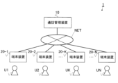
図1は、通話管理システム1の全体構成を示す。図1に示されるように、通話管理システム1は、通話管理装置10、及び端末装置20-1,20-2,…,20-K,…20-Nを備える。Nは1以上の整数である。Kは1以上N未満の整数である。本実施形態において、端末装置20-1~20-Nは同一の構成である。但し、構成が同一でない端末装置が含まれても良い。
1-1: Overall Configuration Fig. 1 shows the overall configuration of the
端末装置20-1~20-Nは、ユーザがチャットアプリを用いて互いに通話することが可能な装置である。端末装置20-1~20-Nは、複数のユーザと1対1に対応する。本実施形態においては、ユーザU1が端末装置20-1を使用する。また、ユーザU2が端末装置20-2を使用する。同様に、ユーザUKが端末装置20-Kを使用する。ユーザUNが端末装置20-Nを使用する。端末装置20-1~20-Nは、例として、スマートフォン又はタブレット端末である。本実施形態において、ユーザによるチャットアプリを用いた通話は、基本的には音声を用いた通話である。しかし、チャットアプリを用いた通話は音声を用いた通話に限定されず、例えば、テキスト情報を用いた通話であってもよい。 The terminal devices 20-1 to 20-N are devices that allow users to talk to each other using a chat app. The terminal devices 20-1 to 20-N correspond one-to-one to multiple users. In this embodiment, user U1 uses terminal device 20-1. User U2 uses terminal device 20-2. Similarly, user UK uses terminal device 20-K. User UN uses terminal device 20-N. The terminal devices 20-1 to 20-N are, for example, smartphones or tablet devices. In this embodiment, calls made by users using a chat app are basically calls using voice. However, calls using a chat app are not limited to calls using voice, and may be calls using text information, for example.
通話管理装置10は、端末装置20-1~20-Nに対して、チャットアプリの機能を提供するサーバである。また、通話管理装置10は、端末装置20-1~20-Nの間の通話を管理する。通話管理装置10は、チャットアプリ機能の提供、及び通話の管理のため、端末装置20-1~20-Nの各々と、通信網NETを介して互いに通信する。
The
1-2:通話管理装置の構成
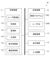
図2は、通話管理装置10の構成例を示すブロック図である。通話管理装置10は、処理装置11、記憶装置12、通信装置13、表示装置14、及び入力装置15を備える。通話管理装置10が有する各要素は、情報を通信するための単体又は複数のバスを用いて相互に接続される。
2 is a block diagram showing an example of the configuration of the
処理装置11は、通話管理装置10の全体を制御するプロセッサである。また、処理装置11は、例えば、単数又は複数のチップを用いて構成される。処理装置11は、例えば、周辺装置とのインタフェース、演算装置及びレジスタ等を含む中央処理装置(CPU)を用いて構成される。なお、処理装置11が有する機能の一部又は全部を、DSP、ASIC、PLD、及びFPGA等のハードウェアを用いて実現してもよい。処理装置11は、各種の処理を並列的又は逐次的に実行する。
The
記憶装置12は、処理装置11による読取及び書込が可能な記録媒体である。また、記憶装置12は、処理装置11が実行する制御プログラムPR1を含む複数のプログラムを記憶する。また、記憶装置12は、ユーザデータベースUDBを記憶する。図3は、ユーザデータベースUDBの構成例を示す表である。ユーザデータベースUDBは、ユーザ毎に、ユーザ名、所属、接続状態、通話状態、通話相手、及び通話可能時間帯を示す情報が格納される。なお、図3に例示される表において、ユーザU1~UNまでのN人分のユーザに関するデータが示される。しかし、当該ユーザの人数は、あくまで一例であり、ユーザデータベースUDBには、任意の人数のユーザのデータが格納される。
The
「ユーザ名」は、各ユーザUの名称を示す。図3に例示される表において、各ユーザ名は、「U1」~「UN」の符号で示されているが、実際には、各ユーザUの個人名であってもよく、各ユーザUのニックネームであってもよい。 "User name" indicates the name of each user U. In the table illustrated in FIG. 3, each user name is indicated by the symbols "U1" to "UN", but in reality, it may be the personal name of each user U or the nickname of each user U.
「所属」は、各ユーザUの所属するグループを示す。例えば、通話管理装置10が提供するチャットアプリを会社内で共用する場合、「所属」は、各ユーザUの所属する部署名であってよい。
"Affiliation" indicates the group to which each user U belongs. For example, if the chat app provided by the
「接続状態」は、各ユーザUが使用する端末装置20が、通話管理システム1に接続されているか否かを示す情報である。当該接続状態は、「オンライン」又は「オフライン」のいずれかのフラグによって表される。図3に例示される表において、ユーザU1の行に示される「オンライン」のフラグは、ユーザU1が使用する端末装置20-1が、通話管理システム1に接続されていることを示す。一方、ユーザU5の行に示される「オフライン」のフラグは、ユーザU5が使用する端末装置20-5が、通話管理システム1に接続されていないことを示す。
"Connection status" is information indicating whether the
「通話状態」は、各ユーザの現在の通話状態を示す情報である。当該通話状態は、「通話可」、「通話中」、及び「通話不可」のいずれかのフラグによって表される。図3に例示される表において、ユーザU1の行に示される「通話可」のフラグは、ユーザU1が、現時点において通話が可能であり、待機中であることを示す。図3に例示される表において、ユーザU4の行に示される「通話中」のフラグは、ユーザU4が現時点において、他の1人又は2人のユーザと通話中であることを示す。図3に例示される表において、ユーザU5の行に示される「通話不可」のフラグは、ユーザU5が現時点において、通話が不可能であることを示す。例えば、現在の時刻が、ユーザU5に関する後述の「通話可能時間帯」に含まれていない場合に、ユーザU5に対応する「通話状態」の欄に、「通話不可」のフラグが設定される。あるいは、ユーザU5が使用する端末装置20-5が、通話管理装置10に接続されていない場合に、ユーザU3に対応する「通話状態」の欄に、「通話不可」のフラグが設定される。
"Call status" is information indicating the current call status of each user. The call status is represented by one of the flags "available for calling", "in call", and "unavailable for calling". In the table illustrated in FIG. 3, the "available for calling" flag shown in the row of user U1 indicates that user U1 is currently available for calling and is waiting. In the table illustrated in FIG. 3, the "in call" flag shown in the row of user U4 indicates that user U4 is currently in a call with one or two other users. In the table illustrated in FIG. 3, the "unavailable for calling" flag shown in the row of user U5 indicates that user U5 is currently unable to make a call. For example, if the current time is not included in the "available for calling time period" for user U5 described later, the "unavailable for calling" flag is set in the "call status" column corresponding to user U5. Alternatively, if the terminal device 20-5 used by user U5 is not connected to the
「通話相手」は、「通話状態」の欄に「通話中」のフラグが設定されている場合に、ユーザUの通話相手を示す情報である。図3に例示される表において、ユーザU4の行に示される「U7」は、ユーザU4の通話相手がユーザU7であることを示す。また、ユーザUNの行に示される「U6、U9」は、ユーザUNの通話相手が、ユーザU6とユーザU9との2名であることを示す。 "Call partner" is information that indicates the call partner of user U when the "Call status" column has the "In call" flag set. In the table illustrated in FIG. 3, "U7" shown in the row of user U4 indicates that the call partner of user U4 is user U7. Also, "U6, U9" shown in the row of user UN indicates that the call partners of user UN are two people, user U6 and user U9.
「通話可能時間帯」は、各ユーザUが通話可能な時間帯を示す。図3に例示される表において、ユーザU1の行に示される、「11月1日 10:00~16:00」、及び「11月4日 15:00~18:00」の2つのデータは、ユーザU1が、11月1日の10:00~16:00、及び11月4日の15:00~18:00に通話が可能であることを示す。なお、ユーザU1に関するデータにおいては、「通話可能時間帯」として、上記のように「11月1日 10:00~16:00」、及び「11月4日 15:00~18:00」の2つの時間帯を示すデータが格納される。しかし、「通話可能時間帯」に2つの時間帯を示すデータが格納されることはあくまで一例であって、任意の個数の時間帯を示すデータが格納されてよい。 "Available call time periods" indicate the time periods during which each user U can make calls. In the table illustrated in FIG. 3, the two pieces of data shown in the row for user U1, "November 1st 10:00-16:00" and "November 4th 15:00-18:00", indicate that user U1 can make calls from 10:00-16:00 on November 1st and from 15:00-18:00 on November 4th. Note that in the data for user U1, data indicating the two time periods, "November 1st 10:00-16:00" and "November 4th 15:00-18:00", as described above, are stored as "available call time periods". However, storing data indicating two time periods in "available call time periods" is merely an example, and data indicating any number of time periods may be stored.
図2において、通信装置13は、他の装置と通信を行うための、送受信デバイスとしてのハードウェアである。通信装置13は、例えば、ネットワークデバイス、ネットワークコントローラ、ネットワークカード、及び通信モジュール等とも呼ばれる。通信装置13は、有線接続用のコネクターを備え、上記コネクターに対応するインタフェース回路を備えていてもよい。また、通信装置13は、無線通信インタフェースを備えていてもよい。有線接続用のコネクター及びインタフェース回路としては有線LAN、IEEE1394、及びUSBに準拠した製品が挙げられる。また、無線通信インタフェースとしては無線LAN及びBluetooth(登録商標)等に準拠した製品が挙げられる。
In FIG. 2, the
表示装置14は、画像及び文字情報を表示するデバイスである。表示装置14は、処理装置11による制御のもとで各種の画像を表示する。例えば、液晶表示パネル及び有機EL(Electro Luminescence)表示パネル等の各種の表示パネルが表示装置14として好適に利用される。
The
入力装置15は、通話管理装置10の管理者からの操作を受け付ける。例えば、入力装置15は、キーボード、タッチパッド、タッチパネル又はマウス等のポインティングデバイスを含んで構成される。ここで、入力装置15は、タッチパネルを含んで構成される場合、表示装置14を兼ねてもよい。
The
処理装置11は、記憶装置12から制御プログラムPR1を読み出して実行する。その結果、処理装置11は、ユーザ管理部111、取得部112、管理部113、生成部114、表示制御部115、及び通話制御部116として機能する。
The
ユーザ管理部111は、通話管理装置10が提供するチャットアプリのユーザUに関するデータを管理する。具体的には、ユーザ管理部111は、一例として、ユーザU1が主体となる操作に応じて、通信網NETを介して端末装置20-1から取得したデータに基づいて、ユーザデータベースUDBに対して、ユーザU1に関する新たなデータを格納する。あるいは、ユーザ管理部111は、当該データに基づいて、ユーザデータベースUDBに格納されるユーザU1に関するデータを更新する。ユーザU2及びユーザU3を含む他のユーザUについても同様である。
The
取得部112は、ユーザUが使用する端末装置20から、他のユーザUを会話の相手として依頼する依頼要求を取得する。一例として、取得部112は、ユーザU1が使用する端末装置20-1から、他のユーザであるユーザU2又はユーザU3を会話の相手として依頼する依頼要求を取得する。また、取得部112は、他のユーザUの各々が使用する端末装置20から、当該依頼要求に対する応答である依頼応答を取得する。当該依頼応答は、依頼要求に対する承諾と、依頼要求に対する拒絶のいずれかである。なお、上記の説明においては、取得部112は、端末装置20-1から依頼要求を取得し、他の端末装置20から依頼応答を取得する例について述べた。しかし、この例はあくまで一例である。取得部112は、任意の端末装置20から依頼要求を取得できる。また、取得部112は、当該任意の端末装置20からの当該依頼要求に対する依頼応答を、当該任意の端末装置20以外の任意の端末装置20から取得できる。
The
また、取得部112は、端末装置20-1~20-Nの各々から、ユーザU1~UNが通話可能な時間帯を示す時間情報を取得する。取得部112は、取得した時間情報を、ユーザ管理部111に出力する。ユーザ管理部111は、取得部112から取得した時間情報に基づいて、上記のように、ユーザデータベースUDB内の「通話可能時間帯」の欄に格納されるデータを更新する。
The
管理部113は、ユーザデータベースUDB内の「通話可能時間帯」の欄に格納されるデータによって示される時間情報と、現在の時刻とに基づいて、現時点において通話可能な1以上のユーザを示す第1ユーザ情報を管理する。例えば現在の時刻が11月1日の12:00である場合、図3に示されるユーザデータベースUDBに格納されるデータに基づけば、第1ユーザ情報は、ユーザU1、ユーザU2、ユーザU3、ユーザU4、ユーザU6、ユーザU7、ユーザU9、ユーザU10、及びユーザUNに設定される。
The
また、通話管理装置10が提供するチャットアプリにおいて、1回の通話に参加できるユーザ数に制限がある場合、管理部113は更に、既に制限人数の上限の人数で通話をしているユーザを、第1ユーザ情報から排除してもよい。例えば現在の時刻が11月1日の12:00である場合、図3に示されるユーザデータベースUDBに基づけば、当初の第1ユーザ情報は、上記のようにユーザU1、ユーザU2、ユーザU3、ユーザU4、ユーザU6、ユーザU7、ユーザU9、ユーザU10、及びユーザUNに設定される。しかし、同時に通話に参加できる人数の上限が3人である場合、ユーザU6、ユーザU9、及びユーザUNは、現時点において3人での通話に参加しているため、管理部113は、第1ユーザ情報から、ユーザU6、ユーザU9、及びユーザUNを排除してもよい。換言すれば、この場合、第1ユーザ情報は、ユーザU1、ユーザU2、ユーザU3、ユーザU4、ユーザU7、及びユーザU10に設定される。
In addition, in the chat app provided by the
また、通話管理装置10が提供するチャットアプリにおいて、1回の通話毎の時間に制限時間が設けられる場合、管理部113は、通話時間が制限時間を超えないことを目的に通話を管理する。例えば、当該チャットアプリにおいて、1回の通話毎の制限時間が3分間に設定されている場合、管理部113は、複数のユーザUの間での通話時間が3分に達した時点において、当該複数のユーザUの間での通話を強制終了する。
In addition, in a chat app provided by the
図2において、生成部114は、通話管理装置10に接続中の端末装置20-1~20-N毎に、第1ユーザ情報の示す通話可能な1以上のユーザU1~UNから、当該端末装置20-1~20-NのユーザU1~UNを除いた第2ユーザ情報を生成する。
In FIG. 2, the
例えば、第1ユーザ情報が、ユーザU1、ユーザU2、ユーザU3、ユーザU4、ユーザU7、及びユーザU10に設定されている場合に、生成部114は、ユーザU1が使用する端末装置20-1に対応する第2ユーザ情報として、第1ユーザ情報からユーザU1を除いた、ユーザU2、ユーザU3、ユーザU4、ユーザU7、及びユーザU10を示す第2ユーザ情報を生成する。また、生成部114は、ユーザU2が使用する端末装置20-2に対応する第2ユーザ情報として、第1ユーザ情報から、ユーザU2を除いた、ユーザU1、ユーザU3、ユーザU4、ユーザU7、及びユーザU10を示す第2ユーザ情報を生成する。
For example, when the first user information is set to user U1, user U2, user U3, user U4, user U7, and user U10, the
表示制御部115は、通話管理装置10に接続中の端末装置20-1~20-N毎に生成された第2ユーザ情報に基づいて、当該端末装置20-1~20-NのユーザU1~UNと通話可能な他のユーザを示す画像を、当該端末装置20-1~20-Nに表示させる。例えば、表示制御部115は、端末装置20-1に対応する第2ユーザ情報に基づいて、当該端末装置20-1のユーザU1と通話可能な他のユーザとして、ユーザU2、ユーザU3、ユーザU4、ユーザU7、及びユーザU10を示す画像を、端末装置20-1に表示させる。また、例えば、表示制御部115は、端末装置20-2に対応する第2ユーザ情報に基づいて、当該端末装置20-2のユーザU2と通話可能な他のユーザとして、ユーザU1、ユーザU3、ユーザU4、ユーザU7、及びユーザU10を示す画像を、端末装置20-2に表示させる。
The
図4は、表示制御部115が、ユーザU1が使用する端末装置20-1に表示させる画面の例である。図4において、第1表示画面DI1は、一例として、ユーザU1が、端末装置20-1において、本実施形態に係るチャットアプリを起動した場合に表示される画面の例である。図4に示されるように、第1表示画面DI1には、ユーザU2に対応するユーザ領域AR2が含まれる。ユーザU2は「第1のユーザ」の一例である。同様に、第1表示画面DI1には、ユーザU3~U6の各々と1対1に対応するユーザ領域AR3~AR6が含まれる。なお、図4に示される例においては、第1表示画面DI1は、ユーザU2~U6に対応する5つのユーザ領域AR2~AR6を含む。しかし、第1表示画面DI1に含まれるユーザ領域ARの数は任意であってよい。
FIG. 4 is an example of a screen that the
ユーザ領域AR2には、第1のユーザとしてのユーザU2を示すユーザ画像P2が含まれる。同様に、ユーザ領域AR3~AR6の各々には、ユーザU3~U6と1対1に対応し、当該ユーザU3~U6を示すユーザ画像P3~P6が含まれる。 User area AR2 includes a user image P2 that shows user U2 as the first user. Similarly, user areas AR3 to AR6 each include user images P3 to P6 that correspond one-to-one to users U3 to U6 and show those users U3 to U6.
ユーザ領域AR2~AR6の各々には、ユーザU2~U6のユーザ名N2~N6、及び通話状態ST2~ST6が表示される。 Each of the user areas AR2 to AR6 displays the user names N2 to N6 of the users U2 to U6 and the call statuses ST2 to ST6.
また、ユーザ領域AR5及びAR6に示されるように、通話状態ST5及びST6が「通話中」となっている場合には、当該ユーザ領域AR5及びAR6の各々中に、ユーザU5及びU6の各々の通話相手のユーザ画像PP5及びPP6が表示される。 Also, as shown in the user areas AR5 and AR6, when the call status ST5 and ST6 are "on a call", the user images PP5 and PP6 of the call partners of users U5 and U6 are displayed in the user areas AR5 and AR6, respectively.
図2において、通話制御部116は、取得部112が、一例として、ユーザU1の端末装置20-1から第1のユーザとしてのユーザU2を通話の相手に指定する要求を取得した場合、ユーザU1とユーザU2とを通話グループとして管理する。また、通話制御部116は、第1のユーザとしてのユーザU2が使用する端末装置20-2に対して、通話グループへの参加を依頼する依頼要求を送信する。取得部112は、端末装置20-2から、依頼要求に対する応答である依頼応答を取得する。取得部112が取得した依頼応答が承諾を示す場合、通話制御部116は、ユーザU1が使用する端末装置20-1とユーザU2が使用する端末装置20-2との間の通話に対する通信を中継する。一方で、取得部112が取得した依頼応答が拒絶を示す場合、通話制御部116は、通話グループの管理を終了する。
In FIG. 2, when the
図4において、詳しくは後述するように、ユーザU1が、第1のユーザとしてのユーザU2のみを通話の相手に指定することを試みる場合、ユーザU2に対応するユーザ領域AR2をタップする。この結果、端末装置20-1から通話管理装置10に対して、第1のユーザとしてのユーザU2を通話の相手に指定する要求が送信される。通話管理装置10において、取得部112が当該要求を取得すると、通話制御部116は、ユーザU1とユーザU2とを通話グループとして管理する。また、通話制御部116は、端末装置20-2に対して、通話グループへの参加を依頼する依頼要求を送信する。取得部112が端末装置20-2から取得した依頼応答が承諾を示す場合、通話制御部116は、端末装置20-1と端末装置20-2との間の通話に対する通信を中継する。一方で、取得部112が取得した依頼応答が拒絶を示す場合、通話制御部116は、通話グループの管理を終了する。
In FIG. 4, as will be described later in detail, when user U1 attempts to designate only user U2 as the first user as the call partner, the user taps the user area AR2 corresponding to user U2. As a result, a request to designate user U2 as the first user as the call partner is transmitted from terminal device 20-1 to call
また、詳しくは後述するように、ユーザU1が、第1のユーザとしてのユーザU2と第2のユーザとの2人を通話の相手に指定することを試みる場合、ユーザU2は、最初にユーザU2に対応するユーザ領域AR2を長押しする。この結果、端末装置20-1において、第1表示画面DI1の一部を覆う方式で第2表示画面DI2が表示される。第2表示画面DI2には、第1のユーザとしてのユーザU2を示すユーザ画像P2、ユーザU2のユーザ名N2、所属G2、接続状態C2、及び通話可能時間帯T2が表示される。また、第2表示画面DI2には、第2のユーザを選択するための第1アイコンI1、及び通話を要求するための第2アイコンI2が表示される。 As will be described in detail later, when user U1 attempts to designate both user U2 as the first user and the second user as call partners, user U2 first presses and holds the user area AR2 corresponding to user U2. As a result, in the terminal device 20-1, the second display screen DI2 is displayed in a manner that covers a part of the first display screen DI1. The second display screen DI2 displays a user image P2 indicating user U2 as the first user, the user name N2 of user U2, affiliation G2, connection status C2, and available call time zone T2. The second display screen DI2 also displays a first icon I1 for selecting the second user, and a second icon I2 for requesting a call.
すなわち、表示制御部115は、ユーザU2の端末装置20-2から取得された時間情報に基づいて、ユーザU2が通話可能な時間帯を端末装置20-1に表示させる。
That is, the
また、ユーザU1が、第1アイコンI1をタップすると、第2表示画面DI2が消え、再度第1表示画面DI1の全体が表示される。ユーザU1は、第2のユーザとして、ユーザU3を通話の相手に指定することを試みる場合、ユーザU3に対応するユーザ領域AR3をタップする。 When user U1 taps the first icon I1, the second display screen DI2 disappears and the entire first display screen DI1 is displayed again. When user U1, as the second user, attempts to designate user U3 as the other party of a call, he or she taps the user area AR3 corresponding to user U3.
図5は、ユーザU1がユーザ領域AR3をタップすることによって表示される第3表示画面DI3の例である。第3表示画面DI3には、第2表示画面DI2と同様に、第1のユーザとしてのユーザU2を示すユーザ画像P2、ユーザU2のユーザ名N2、所属G2、接続状態C2、及び通話可能時間帯T2が表示される。更に、第3表示画面DI3には、第2のユーザとしてのユーザU3を示すユーザ画像P3、ユーザU3のユーザ名N3、所属G3、接続状態C3、及び通話可能時間帯T3が表示される。 Figure 5 is an example of the third display screen DI3 that is displayed when user U1 taps on user area AR3. As with the second display screen DI2, the third display screen DI3 displays a user image P2 indicating user U2 as the first user, the user name N2 of user U2, affiliation G2, connection status C2, and available call time zone T2. Furthermore, the third display screen DI3 displays a user image P3 indicating user U3 as the second user, the user name N3 of user U3, affiliation G3, connection status C3, and available call time zone T3.
図6は、ユーザU1が、第2アイコンI2をタップした結果、ユーザU2及びU3の双方と通話状態になった場合に、表示される第4表示画面DI4の例である。第4表示画面DI4の上部には、ユーザU1の通話相手である、ユーザU2を示すユーザ画像P2、ユーザU2のユーザ名N2、ユーザU3を示すユーザ画像P3、及びユーザU3のユーザ名N3が表示される。また、ユーザU2及びU3との通話時間に制限時間が設定されている場合、第4表示画面DI4の中央部には、残り時間の表示を要求するための第3アイコンI3が表示される。 Figure 6 shows an example of the fourth display screen DI4 that is displayed when user U1 taps the second icon I2 and enters a call state with both users U2 and U3. At the top of the fourth display screen DI4, a user image P2 representing user U2, who is the call partner of user U1, a username N2 of user U2, a user image P3 representing user U3, and a username N3 of user U3 are displayed. In addition, if a time limit is set for the call time with users U2 and U3, a third icon I3 for requesting a display of the remaining time is displayed in the center of the fourth display screen DI4.
更に、第4表示画面DI4の一部を覆う方式で第5表示画面DI5が表示される。第5表示画面DI5には、通話を終了させるための第4アイコンI4、ユーザU1の音声を収音するために用いる後述のマイク26をミュートするための第5アイコンI5、及び、ユーザU2及びユーザU3の音声を、後述のスピーカ27から放音するための第6アイコンI6が表示される。 Furthermore, a fifth display screen DI5 is displayed in a manner that covers a part of the fourth display screen DI4. On the fifth display screen DI5, a fourth icon I4 for ending the call, a fifth icon I5 for muting a microphone 26 (described below) that is used to pick up the voice of user U1, and a sixth icon I6 for emitting the voices of users U2 and U3 from a speaker 27 (described below) are displayed.
ユーザU1が第3アイコンI3をタップすると、第4表示画面DI4は、第6表示画面DI6に変化する。第6表示画面DI6においては、中央部に、通話の残り時間を表示する第7アイコンI7が表示される。 When the user U1 taps the third icon I3, the fourth display screen DI4 changes to the sixth display screen DI6. In the sixth display screen DI6, a seventh icon I7 that displays the remaining time of the call is displayed in the center.
具体的には、端末装置20-1において、ユーザU1が第3アイコンI3をタッチ操作した場合、端末装置20-1から、通話管理装置10に対して、ユーザU間の通話の残り時間を問い合わせる問い合わせ要求が送信される。取得部112は、当該問い合わせ要求を取得する。取得部112が当該問い合わせ要求を取得すると、表示制御部115は、当該問い合わせ要求に対する応答として、ユーザU1、ユーザU2、及びユーザU3の間の通話の残り時間を端末装置20-1に表示させる。
Specifically, when user U1 touches the third icon I3 on the terminal device 20-1, a query request is sent from the terminal device 20-1 to the
図7は、図4に示される第1表示画面DI1において、ユーザU1が、第1のユーザとしてのユーザU2のみを通話の相手に指定することを試みるために、ユーザU2に対応するユーザ領域AR2をタップした後、ユーザU2と通話状態になった場合に表示される第7表示画面DI7の例である。第7表示画面DI7においては、ユーザU2を示すユーザ画像P2、及びユーザU2のユーザ名N2が表示される一方で、第4表示画面DI4及び第6表示画面DI6とは異なり、ユーザU3を示すユーザ画像P3、及びユーザU3のユーザ名N3は表示されない。 Figure 7 is an example of a seventh display screen DI7 that is displayed when user U1 taps the user area AR2 corresponding to user U2 on the first display screen DI1 shown in Figure 4 in order to attempt to specify only user U2 as the first user as the call partner, and then a call state is established with user U2. On the seventh display screen DI7, a user image P2 representing user U2 and a username N2 of user U2 are displayed, but unlike the fourth display screen DI4 and the sixth display screen DI6, a user image P3 representing user U3 and a username N3 of user U3 are not displayed.
1-3:端末装置の構成
図8は、端末装置20の構成例を示すブロック図である。端末装置20は、処理装置21、記憶装置22、通信装置23、表示装置24、入力装置25、マイク26、及びスピーカ27を備える。端末装置20が有する各要素は、情報を通信するための単体又は複数のバスを用いて相互に接続される。
1-3: Configuration of Terminal Device Fig. 8 is a block diagram showing a configuration example of the
処理装置21は、端末装置20の全体を制御するプロセッサである。また、処理装置21は、例えば、単数又は複数のチップを用いて構成される。処理装置21は、例えば、周辺装置とのインタフェース、演算装置及びレジスタ等を含む中央処理装置(CPU)を用いて構成される。なお、処理装置11が有する機能の一部又は全部を、DSP、ASIC、PLD、及びFPGA等のハードウェアを用いて実現してもよい。処理装置21は、各種の処理を並列的又は逐次的に実行する。
The
記憶装置22は、処理装置21による読取及び書込が可能な記録媒体である。また、記憶装置22は、処理装置21が実行する制御プログラムPR2を含む複数のプログラムを記憶する。なお、制御プログラムPR2は、一例として、通話管理装置10からダウンロードされたプログラムであってもよい。
The
通信装置23は、他の装置と通信を行うための、送受信デバイスとしてのハードウェアである。通信装置23は、例えば、ネットワークデバイス、ネットワークコントローラ、ネットワークカード、及び通信モジュール等とも呼ばれる。通信装置23は、有線接続用のコネクターを備え、上記コネクターに対応するインタフェース回路を備えていてもよい。また、通信装置23は、無線通信インタフェースを備えていてもよい。有線接続用のコネクター及びインタフェース回路としては有線LAN、IEEE1394、及びUSBに準拠した製品が挙げられる。また、無線通信インタフェースとしては無線LAN及びBluetooth(登録商標)等に準拠した製品が挙げられる。とりわけ本実施形態において、通信装置23は、ユーザU間の通話を管理する通話管理装置10と通信する。
The
表示装置24は、画像及び文字情報を表示するデバイスである。表示装置24は、処理装置21による制御のもとで各種の画像を表示する。例えば、液晶表示パネル及び有機EL(Electro Luminescence)表示パネル等の各種の表示パネルが表示装置24として好適に利用される。
The
入力装置25は、ユーザUからの操作を受け付ける。例えば、入力装置25は、キーボード、タッチパッド、タッチパネル又はマウス等のポインティングデバイスを含んで構成される。ここで、入力装置25は、タッチパネルを含んで構成される場合、表示装置24を兼ねてもよい。あるいは、表示装置24は、入力装置25を含んでもよい。すなわち、表示装置24は、画像及び文字情報を表示すると共に、当該画像の表示面へのタッチ操作を受け付けてもよい。
The
マイク26は、音声を収音し、収音した音声に基づく音声データを、処理装置21に出力する。例えば、ユーザU1が端末装置20-1を使用することで、ユーザU2及びユーザU3と通話をする場合、マイク26は、ユーザU1の音声を収音し、収音した音声に基づく音声データを、処理装置21に出力する。
The
スピーカ27は音声を放音するデバイスである。スピーカ27は、処理装置21による制御のもとで、各種の音声を放音する。例えば、デジタル信号である音声データが、図示しないDA変換器によってアナログ信号である音声信号に変換される。当該音声信号は、図示しないアンプによって、振幅が増幅される。スピーカ27は、振幅が増幅された後の音声信号によって示される音声を放音する。例えば、ユーザU1が端末装置20-1を用いて、ユーザU2及びユーザU3と通話をする場合、スピーカ27は、ユーザU2及びユーザU3の音声を放音する。
The
処理装置21は、記憶装置22から制御プログラムPR2を読み出して実行する。その結果、処理装置21は、認証部211、表示制御部212、判定部213、特定部214、要求部215、取得部216、及び通話部217として機能する。
The
認証部211は、端末装置20のユーザUを認証する。具体的には、ユーザU1が端末装置20-1を、通話管理システム1に接続させて、本実施形態に係るチャットアプリを使用する場合、認証部211は、ユーザU1の当該チャットアプリへのログイン時に、ユーザU1を認証する。
The
表示制御部212は、通信装置23を介して受信した情報に基づいて、会話可能な複数のユーザUに1対1に対応する複数のユーザ画像Pを、表示装置24に表示させる。
Based on the information received via the
上記のように、通話管理装置10に備わる表示制御部115は、図4に例示される第1表示画面DI1を、端末装置20-1に表示させる。この場合、表示制御部212は、通信装置23を介して、通話管理装置10から受信した情報に基づいて、第1表示画面DI1を表示装置24に表示させる。当該第1表示画面DI1には、会話可能な複数のユーザU2~U6に1対1に対応するユーザ画像P2~P6が含まれる。当該ユーザ画像P2~P6の各々は、ユーザ領域AR2~AR6に含まれる。
As described above, the
判定部213は、表示装置24に備わる表示面に対する人の指が接触する時間に基づいて、タッチ操作が第1のタッチ操作であるか第2のタッチ操作であるかを判定する。ここで、ユーザU1が主体となった、ユーザ領域AR2へのタップは、「第1のタッチ操作」の一例である。また、ユーザU1が主体となった、ユーザ領域AR2への長押しは、「第2のタッチ操作」の一例である。
The
一例として、表示装置24が、入力装置25としてのタッチパネルを備える場合、判定部213は、当該タッチパネルへのユーザU1の指が接触する時間に基づいて、ユーザU1が主体となったタッチ操作が、第1のタッチ操作か、又は第2のタッチ操作かを判定する。
As an example, if the
特定部214は、複数のユーザ領域AR2~AR6のうち第1のユーザ領域AR2に対して第1のタッチ操作がなされた場合、特定部214は、第1のユーザ領域AR2に含まれる第1のユーザ画像P2に対応する第1のユーザU2を会話の相手として特定する。また、特定部214は、第1のユーザ領域AR2に対して第2のタッチ操作がなされた場合、第1のユーザU2の他に会話の相手が指定されることを特定する。
When a first touch operation is performed on a first user area AR2 among the multiple user areas AR2 to AR6, the
上記のように、図4に例示される第1表示画面DI1において、ユーザU1は、第1のユーザとしてのユーザU2のみを通話の相手に指定することを試みる場合、ユーザU2に対応するユーザ領域AR2をタップする。この場合、特定部214は、第1のユーザ領域AR2に含まれる第1のユーザ画像P2に対応する第1のユーザU2を会話の相手として特定する。
As described above, on the first display screen DI1 illustrated in FIG. 4, when user U1 attempts to designate only user U2 as the first user as the conversation partner, user U1 taps the user area AR2 corresponding to user U2. In this case, the
また、第1表示画面DI1において、ユーザU1が、第1のユーザとしてのユーザU2と第2のユーザとの2人を通話の相手に指定することを試みる場合、ユーザU2は、最初にユーザU2に対応するユーザ領域AR2を長押しする。この場合、特定部214は、第1のユーザU2の他に会話の相手が指定されることを特定する。
When user U1 attempts to designate both user U2 as the first user and the second user as call partners on the first display screen DI1, user U2 first presses and holds the user area AR2 corresponding to user U2. In this case, the
また、特定部214は、第2のタッチ操作を受け付けた後に、複数のユーザ領域AR2~AR6のうち第2のユーザ領域AR3に対して第1のタッチ操作がなされた場合、第2のユーザ領域AR3に含まれる第2のユーザ画像P3に対応する第2のユーザU3及び第1のユーザU2を会話の相手として特定する。
Furthermore, when a first touch operation is performed on a second user area AR3 among the multiple user areas AR2 to AR6 after receiving a second touch operation, the
具体的には、図4に例示される第2表示画面DI2において、ユーザU1が、第1アイコンI1をタップすると、第2表示画面DI2が消え、再度第1表示画面DI1の全体が表示される。ユーザU1は、第2のユーザとして、ユーザU3を通話の相手に指定することを試みる場合、ユーザU3に対応するユーザ画像P3を含むユーザ領域AR3をタップする。この場合、特定部214は、第2のユーザ画像P3に対応する第2のユーザU3及び第1のユーザU2を会話の相手として特定する。
Specifically, when user U1 taps the first icon I1 on the second display screen DI2 illustrated in FIG. 4, the second display screen DI2 disappears and the entire first display screen DI1 is displayed again. When user U1, as the second user, attempts to designate user U3 as a call partner, he/she taps the user area AR3 including the user image P3 corresponding to user U3. In this case, the
図8において、要求部215は、特定部214によって特定された第1のユーザとしてのユーザU2、又は第1のユーザとしてのユーザU2、及び第2のユーザとしてのユーザU3の組を、会話の相手として依頼する依頼要求を、通信装置23を介して通話管理装置10に送信する。この結果、上記のように、通話管理装置10に備わる取得部112は、当該依頼要求を取得する。
In FIG. 8, the
例えば、図4において、ユーザU1が、第1のユーザ領域AR2をタップすると、特定部214が、第1のユーザとしてのユーザU2を特定する。ユーザU2が特定されると、要求部215は、第1のユーザとしてのユーザU2を、会話の相手として依頼する依頼要求を、通信装置23を介して通話管理装置10に送信する。
For example, in FIG. 4, when user U1 taps the first user area AR2, the
あるいは、図4において、ユーザU1が、第1のユーザ領域AR2を長押しすることで、第2表示画面DI2を表示させた後、第1アイコンI1をタップし、第1表示画面DI1において、第2のユーザ領域AR3をタップすると、特定部214が、第1のユーザとしてのユーザU2、及び第2のユーザとしてのユーザU3を特定する。その後、ユーザU1は、通話を要求するための第2アイコンI2をタップする。第2アイコンI2がタップされると、要求部215は、第1のユーザとしてのユーザU2、及び第2のユーザとしてのユーザU3を、会話の相手として依頼する依頼要求を、通信装置23を介して通話管理装置10に送信する。
Alternatively, in FIG. 4, when user U1 displays the second display screen DI2 by long pressing the first user area AR2, taps the first icon I1, and then taps the second user area AR3 on the first display screen DI1, the
また、要求部215は、所定のアイコンがタッチ操作された場合、通信装置23を介して、ユーザU間の通話の残り時間を問い合わせる問い合わせ要求を通話管理装置10に送信する。例えば、図6における、第3アイコンI3は、「所定のアイコン」の一例である。表示制御部212は、通信装置23を介して、通話管理装置10から、問い合わせ要求に対する応答を受信した場合に、問い合わせ要求に対する応答が示す残り時間を表示装置24に表示させる。例えば、表示制御部212は、図6に例示される第7アイコンI7によって、当該残り時間を表示装置24に表示させる。
When a specific icon is touched, the
上記のように、端末装置20-1から通話管理装置10に対して、一例として、第1のユーザとしてのユーザU2を通話の相手に指定する要求が送信された場合、通話管理装置10に備わる通話制御部116は、ユーザU1とユーザU2とを通話グループとして管理する。また、通話制御部116は、端末装置20-2に対して、通話グループへの参加を依頼する依頼要求を送信する。通話管理装置10に備わる取得部112が端末装置20-2から取得した依頼応答が承諾を示す場合、通話制御部116は、当該承諾を示す依頼応答を、端末装置20-1に送信する。取得部216は、当該依頼応答を取得する。
As described above, when a request is sent from terminal device 20-1 to call
この場合、表示制御部212は、依頼が承諾されたことを示す画面を、表示装置24に表示させる。端末装置20-1が、通話管理装置10に対して、第1のユーザとしてのユーザU2のみを通話の相手に指定する要求を送信した後、通話管理装置10から、承諾を示す依頼応答を取得した場合、表示制御部212は、依頼が承諾されたことを示す画面として、図7に例示される第7表示画面DI7を表示させる。
In this case, the
通話部217は、通信装置23を制御することによって通話管理装置10を介して、承諾したユーザU2が使用する他の端末装置20-2との間の通話を実行する。上記のように、通話制御部116は、端末装置20-1と端末装置20-2との間の通話に対する通信を中継する。
The
一方で、通話管理装置10に備わる取得部112が端末装置20-2から取得した依頼応答が拒絶を示す場合、通話制御部116は、当該拒絶を示す依頼応答を、端末装置20-1に送信する。取得部216は、当該依頼応答を取得する。
On the other hand, if the request response acquired by the
この場合、表示制御部212は、依頼が拒絶されたことを示す画面を、表示装置24に表示させる。一例として、端末装置20-1が、通話管理装置10に対して、第1のユーザとしてのユーザU2のみを通話の相手に指定する要求を送信した後、通話管理装置10から、拒絶を示す依頼応答を取得した場合、表示制御部212は、依頼が拒絶されたことを示す画面を、表示装置24に表示させる。図9は、当該画面としての第8表示画面DI8の例である。第8表示画面DI8には、ユーザU2のユーザ画像P2、ユーザU2のユーザ名N2、通話ができないことを示す第8アイコンI8、及び第8表示画面DI8を消去するために使用される第9アイコンI9が含まれる。
In this case, the
また、別の一例として、端末装置20-1から通話管理装置10に対して、第1のユーザとしてのユーザU2と、第2のユーザとしてのユーザU3とを通話の相手に指定する要求が送信された場合、通話管理装置10に備わる通話制御部116は、ユーザU1、ユーザU2、及びユーザU3を通話グループとして管理する。また、通話制御部116は、端末装置20-2及び20-3に対して、通話グループへの参加を依頼する依頼要求を送信する。通話管理装置10に備わる取得部112が端末装置20-2及び20-3のうち一方から取得した依頼応答が承諾を示す場合、通話制御部116は、当該承諾を示す依頼応答を、端末装置20-1に送信する。取得部216は、当該依頼応答を取得する。この場合、通話部217は、通信装置23を制御することによって通話管理装置10を介して、承諾したユーザが使用する端末装置20-2及び20-3のうち一方との間の通話を実行する。
As another example, when a request is sent from the terminal device 20-1 to the
この場合、表示制御部212は、一方のユーザが依頼を承諾したことを示す画面を、表示装置24に表示させる。図10は、一方のユーザが依頼を承諾したことを示す画面としての第9表示画面DI9の例である。端末装置20-1が、通話管理装置10に対して、第1のユーザとしてのユーザU2及び第2のユーザU3を通話の相手に指定する要求を送信した後、通話管理装置10から、ユーザU2からの承諾を示す依頼応答を取得した場合、表示制御部212は、依頼が承諾されたことを示す画面として第9表示画面DI9を表示させる。第9表示画面DI9は、第7表示画面DI7と同様に、ユーザU2を示すユーザ画像P2、ユーザU2のユーザ名N2、及び第3アイコンI3を含む。
In this case, the
また、表示制御部212は、ユーザU2からの承諾を示す依頼応答より前に、ユーザU3が依頼を拒絶したことを示す依頼応答を受信していない場合、ユーザU3が依頼に対して回答していないことを示す画面を表示装置24に表示させる。換言すれば、端末装置20-1が、既にユーザU2からの承諾を示す依頼応答を取得していながら、ユーザU3からは未だ依頼に対する依頼応答を取得していない場合に、表示制御部212は、ユーザU3が依頼に対して回答していないことを示す画面を表示装置24に表示させる。図10に示される例において、表示制御部212は、ユーザU3が依頼に対して回答していないことを示す画面として、第9表示画面DI9の一部を覆う方式で、第10表示画面DI10を表示させる。第10表示画面DI10は、ユーザU3を示すユーザ画像P3、ユーザU3のユーザ名N3、及び、ユーザU3が回答待ちであることを示す第10アイコンI10を含む。
In addition, when the
なお、図10に示される例において、第10表示画面DI10の一部を覆う方式で、第5表示画面DI5が表示される。 In the example shown in FIG. 10, the fifth display screen DI5 is displayed in a manner that covers a portion of the tenth display screen DI10.
あるいは、通話部217は、通話管理装置10から、ユーザU2及びユーザU3のうち一方が承諾したことを示す依頼応答を受信した後、通話管理装置10から、ユーザU2及びユーザU3のうち他方も承諾したことを示す依頼応答を受信したことを条件に、通話を実行してもよい。また、通話部217は、通話管理装置10から、ユーザU2及びユーザU3のうち一方のユーザが依頼を拒絶したことを示す依頼応答を受信した場合、通話を実行しなくてもよい。この場合、表示制御部212は、通話が実行されないことを示す画面を、表示装置24に表示させる。
Alternatively, the
図11は、通話が実行されないことを示す画面である第12表示画面DI12の例である。なお、図11に示される例は、ユーザU3が依頼を拒絶した場合を示す。図11に示される例においては、第11表示画面DI11の一部を覆う方式で、第12表示画面DI12が表示される。第11表示画面DI11は、ユーザU2のユーザ画像P2及びユーザU2のユーザ名N2を含む。第12表示画面DI12は、ユーザU3のユーザ画像P3、ユーザU3のユーザ名N3、及び通話ができないことを示す第11アイコンI11、第11表示画面DI11及び第12表示画面DI12を消去するために使用される第12アイコンI12を含む。なお、ユーザU1が第12アイコンI12をタップすることにより、第11表示画面DI11及び第12表示画面DI12を消去した場合、表示制御部212は、図4に示されるように、第1表示画面DI1を表示させてもよく、第1表示画面DI1の一部を覆う方式で、第2表示画面DI2を表示させてもよい。
Figure 11 is an example of the 12th display screen DI12, which is a screen indicating that the call will not be made. Note that the example shown in Figure 11 shows a case where user U3 rejects the request. In the example shown in Figure 11, the 12th display screen DI12 is displayed in a manner that covers a part of the 11th display screen DI11. The 11th display screen DI11 includes a user image P2 of user U2 and a user name N2 of user U2. The 12th display screen DI12 includes a user image P3 of user U3, a user name N3 of user U3, an 11th icon I11 indicating that the call cannot be made, and a 12th icon I12 used to erase the 11th display screen DI11 and the 12th display screen DI12. When the user U1 taps the twelfth icon I12 to erase the eleventh display screen DI11 and the twelfth display screen DI12, the
なお、上記の説明においては、ユーザU2が「第1のユーザ」であり、ユーザU3が「第2のユーザ」である例について述べた。しかし、この例はあくまで一例である。第1のユーザ及び第2のユーザの各々は、任意のユーザUであって良い。 In the above explanation, an example was described in which user U2 is the "first user" and user U3 is the "second user." However, this is merely an example. Each of the first user and the second user may be any user U.
2:実施形態の動作
図12A~図12Cは、本実施形態に係る端末装置20の動作例を示すフローチャートである。
2: Operation of the embodiment FIGS. 12A to 12C are flowcharts showing an example of the operation of the
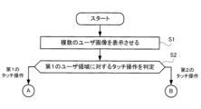
ステップS1において、処理装置21は、表示制御部212として機能する。処理装置21は、通信装置23を介して受信した情報に基づいて、会話可能な複数のユーザに1対1に対応する複数のユーザ画像Pを表示装置24に表示させる。より具体的には、処理装置21は、複数のユーザ画像Pの各々を含む複数のユーザ領域ARを表示装置24に表示させる。
In step S1, the
ステップS2において、処理装置21は、判定部213として機能する。処理装置21は、複数のユーザ領域AR2~AR6のうち第1のユーザ領域AR2に対して第1のタッチ操作がなされたか、第2のタッチ操作がなされたかを判定する。第1のユーザ領域AR2に対して第1のタッチ操作がなされた場合、処理装置21は、ステップS3の処理を実行する。第1のユーザ領域AR2に対して第2のタッチ操作がなされた場合、処理装置21は、ステップS10の処理を実行する。
In step S2, the
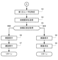
ステップS3において、処理装置21は、特定部214として機能する。処理装置21は、第1のユーザ領域AR2に含まれる第1のユーザ画像P2に対応する第1のユーザU2を会話の相手として特定する。
In step S3, the
ステップS4において、処理装置21は、要求部215として機能する。処理装置21は、第1のユーザとしてのユーザU2を会話の相手として依頼する依頼要求を、通信装置23を介して通話管理装置10に送信する。
In step S4, the
ステップS5において、処理装置21は、取得部216として機能する。処理装置21は、通話管理装置10から依頼応答を取得する。当該依頼応答が承諾を示す場合、処理装置21は、ステップS6の処理を実行する。一方で、当該依頼応答が拒否を示す場合、処理装置21は、ステップS8の処理を実行する。
In step S5, the
ステップS6において、処理装置21は、表示制御部212として機能する。処理装置21は、依頼が承諾されたことを示す画面を、表示装置24に表示させる。
In step S6, the
ステップS7において、処理装置21は、通話部217として機能する。処理装置21は、通信装置23を制御することによって通話管理装置10を介して、承諾したユーザU2が使用する他の端末装置20-2との間の通話を実行する。端末装置20-1と端末装置20-2との間の通話が終了した後、処理装置21は、ステップS1の処理を実行する。
In step S7, the
ステップS8において、処理装置21は、表示制御部212として機能する。処理装置21は、依頼が拒絶されたことを示す画面を、表示装置24に表示させる。
In step S8, the
ステップS9において、処理装置21は、表示制御部212として機能する。処理装置21は、ユーザU1が主体となった操作に基づいて、ステップS8において表示させた画面を消去する。その後、処理装置21は、ステップS1の処理を実行する。
In step S9, the
ステップS10において、処理装置21は、特定部214として機能する。処理装置21は、第1のユーザの他に会話の相手が指定されることを特定する。
In step S10, the
ステップS11において、処理装置21は、判定部213として機能する。処理装置21は、複数のユーザ領域AR2~AR6のうち第2のユーザ領域AR3に対して第1のタッチ操作がなされたか否かを判定する。第2のユーザ領域AR3に対して第1のタッチ操作がなされた場合、処理装置21は、ステップS12の処理を実行する。第2のユーザ領域AR3に対して第1のタッチ操作がなされていない場合、処理装置21は、ステップS11の処理を実行する。
In step S11, the
ステップS12において、処理装置21は、特定部214として機能する。処理装置21は、第1のユーザU2、及び第2のユーザ領域AR3に含まれる第2のユーザ画像P3に対応する第2のユーザU3を会話の相手として特定する。
In step S12, the
ステップS13において、処理装置21は、要求部215として機能する。処理装置21は、第1のユーザとしてのユーザU2、及び第2のユーザとしてのユーザU3を会話の相手として依頼する依頼要求を、通信装置23を介して通話管理装置10に送信する。
In step S13, the
ステップS14において、処理装置21は、取得部216として機能する。処理装置21は、通話管理装置10から、ユーザU2からの依頼応答とユーザU3からの依頼応答とを取得する。双方の依頼応答のうち少なくとも一方が承諾を示す場合、処理装置21は、ステップS15の処理を実行する。一方で、双方の依頼応答が拒否を示す場合、処理装置21は、ステップS17の処理を実行する。
In step S14, the
ステップS15において、処理装置21は、表示制御部212として機能する。処理装置21は、依頼が承諾されたことを示す画面を、表示装置24に表示させる。
In step S15, the
ステップS16において、処理装置21は、通話部217として機能する。処理装置21は、通信装置23を制御することによって通話管理装置10を介して、ユーザU2が使用する他の端末装置20-2、及びユーザU3が使用する他の端末装置20-3のうち少なくとも一方との間の通話を実行する。端末装置20-1と端末装置20-2との間の二者間の通話、端末装置20-1と端末装置20-3との間の二者間の通話、又は端末装置20-1、端末装置20-2、及び端末装置20-3の間の三者間の通話が終了した後、処理装置21は、ステップS1の処理を実行する。
In step S16, the
ステップS17において、処理装置21は、表示制御部212として機能する。処理装置21は、依頼が拒絶されたことを示す画面を、表示装置24に表示させる。
In step S17, the
ステップS18において、処理装置21は、表示制御部212として機能する。処理装置21は、ユーザU1が主体となった操作に基づいて、ステップS17において表示させた画面を消去する。その後、処理装置21は、ステップS1の処理を実行する。
In step S18, the
3:実施形態が奏する効果
以上の説明によれば、端末装置20は、表示装置24と、通信装置23と、表示制御部212と、特定部214と、要求部215とを備える。表示装置24は、画像を表示すると共に当該画像の表示面へのタッチ操作を受け付ける。通信装置23は、ユーザU間の通話を管理する通話管理装置10と通信する。表示制御部212は、通信装置23を介して受信した情報に基づいて、会話可能な複数のユーザUに1対1に対応する複数のユーザ画像Pを含むユーザ領域ARを表示装置24に表示させる。特定部214は、複数のユーザ領域ARのうち第1のユーザ画像P2を含むユーザ領域AR2に対して第1のタッチ操作がなされた場合、第1のユーザ画像P2に対応する第1のユーザU2を会話の相手として特定する。特定部214は、第1のユーザ領域AR2に対して第2のタッチ操作がなされた場合、第1のユーザU2の他に会話の相手が指定されることを特定する。特定部214は、第2のタッチ操作を受け付けた後に、複数のユーザ領域ARのうち第2のユーザ画像P3を含む第2のユーザ領域AR3に対して第1のタッチ操作がなされた場合、第2のユーザ画像P3に対応する第2のユーザU3及び第1のユーザU2を会話の相手として特定する。要求部215は、特定部214によって特定された第1のユーザU2、又は第1のユーザU2及び第2のユーザU3の組を、会話の相手として依頼する依頼要求を、通信装置23を介して通話管理装置10に送信する。
3: Effects of the embodiment According to the above description, the
端末装置20は、上記の構成を備えるので、端末装置20-1のユーザU1は、単純な操作によって、第1のユーザU2との間の2人のチャットも、第1のユーザU2及び第2のユーザU3との間の3人のチャットも開始できる。当該端末装置20-1のユーザU1は、1人の他のユーザである第1のユーザU2のみを招待する場合と、複数の他のユーザである、第1のユーザU2及び第2のユーザU3の2名を招待する場合とで、操作の内容を切り替える。この結果、端末装置20-1のユーザは、単一の操作によって、1人のユーザUを招待するか、2人のユーザUを招待するかを切り替えることが可能となる。
Since the
また、以上の説明によれば、端末装置20は、判定部213を更に備える。判定部213は、表示面に対する人の指が接触する時間に基づいて、上記のタッチ操作が第1のタッチ操作であるか第2のタッチ操作であるかを判定する。
Furthermore, according to the above description, the
端末装置20は、上記の構成を備えるので、第1のユーザU2のみを招待するための操作と、第1のユーザU2及び第2のユーザU3の2名を招待するための操作とで、端末装置20-1への画面の接触時間のみを切り替えることにより、第1のユーザU2のみを招待するか、第1のユーザU2及び第2のユーザU3の2名を招待するかを、シームレスに切り替えることが可能となる。
Since the
また、以上の説明によれば、端末装置20は、通話部217を更に備える。通話部217は、通信装置23を介して通話管理装置10から受信した依頼要求に対する依頼応答が、上記の依頼に対する承諾を示す場合に、通信装置23を制御することによって通話管理装置10を介して、承諾したユーザUが使用する他の端末装置20との間の通話を実行する。表示制御部212は、上記の依頼応答が依頼に対する承諾を示す場合に、依頼が受諾されたことを示す画面を表示装置24に表示させる。また、表示制御部212は、上記の依頼応答が依頼に対する拒絶を示す場合に、依頼が拒絶されたことを示す画面を表示装置24に表示させる。
According to the above description, the
端末装置20は、上記の構成を備えるので、第1のユーザU2への参加依頼に対する承諾を示す、第1のユーザU2の操作があった場合に、ユーザU1は、第1のユーザU2との間で通話できる。
Since the
また、以上の説明によれば、依頼要求は、第1のユーザU2及び第2のユーザU3を、会話の相手として依頼することを示す。通話部217は、上記の依頼応答が、第1のユーザU2及び第2のユーザU3のうち一方のユーザUが上記の依頼を承諾したことを示す場合、通信装置23を制御することによって通話管理装置10を介して、一方のユーザUが使用する他の端末装置との間の通話を実行する。表示制御部212は、上記の依頼応答が、第1のユーザU2及び第2のユーザU3のうち一方のユーザが上記の依頼を承諾したことを示す場合、一方のユーザUが上記の依頼を受諾したことを示す画面を表示装置24に表示させる。また、表示制御部212は、依頼応答より前に、第1のユーザU2及び第2のユーザU3のうち他方のユーザUが上記の依頼を拒絶したことを示す依頼応答を受信していない場合、他方のユーザUが上記の依頼に対して回答していないことを示す画面を表示装置24に表示させる。
According to the above description, the request request indicates that the first user U2 and the second user U3 are requested to be conversation partners. When the request response indicates that one of the first user U2 and the second user U3 has accepted the request, the
端末装置20は、上記の構成を備えるので、第1のユーザU2への参加依頼に対する承諾を示す、第1のユーザU2の操作があった場合に、ユーザU1は、第1のユーザU2との間で通話できる。また、第2のユーザU3への参加依頼に対する承諾を示す、第2のユーザU3の操作がまだない場合に、ユーザU1は、第2のユーザU3を待機できる。
Since the
また、以上の説明によれば、依頼要求は、第1のユーザU2及び第2のユーザU3を、会話の相手として依頼することを示す。通話部217は、依頼応答が、第1のユーザU2及び第2のユーザU3のうち一方のユーザUが上記の依頼を承諾したことを示す場合、他方のユーザUが上記の依頼を承諾したことを示す依頼応答を、通信装置23を介して通話管理装置10から受信したことを条件に、通話を実行する。また、通話部217は、第1のユーザU2及び第2のユーザU3のうち一方のユーザUが上記の依頼を拒絶したことを示す場合、通話を実行しない。表示制御部212は、上記の依頼応答が、第1のユーザU2及び第2のユーザU3のうち一方のユーザUが上記の依頼を拒絶したことを示す場合、通話が実行されないことを示す画面を表示装置24に表示させる。
According to the above description, the request request indicates that the first user U2 and the second user U3 are requested to be conversation partners. If the request response indicates that one of the first user U2 and the second user U3 has accepted the request, the
端末装置20は、上記の構成を備えるので、第1のユーザU2への参加依頼に対する拒絶を示す操作と、第2のユーザU3への参加依頼に対する拒絶を示す操作のうち、少なくとも一方の操作が存在した場合に、端末装置20-1のユーザであるユーザU1、第1のユーザU2、及び第2のユーザU3との間の通話が、そもそも開始されない。
Since the
また、以上の説明によれば、通話管理装置10は、通話時間が制限時間を超えないことを目的に通話を管理する。表示制御部212は、通話中に表示装置24に所定のアイコンを表示させる。要求部215は、所定のアイコンがタッチ操作された場合、通信装置23を介して、ユーザU間の通話の残り時間を問い合わせる問い合わせ要求を通話管理装置10に送信する。表示制御部212は、通信装置23を介して、問い合わせ要求に対する応答を受信した場合に、問い合わせ要求に対する応答が示す残り時間を表示装置24に表示させる。
Furthermore, according to the above description, the
端末装置20は、上記の構成を備えるので、端末装置20-1から所定の操作がされて初めて、通話管理装置10から端末装置20-1に対して残りの使用可能時間を表示させることで、通信データ量が抑制されることにより、通信負荷が低減される。
Since the
また、以上の説明によれば、情報処理用プログラムとしての制御プログラムPR2は、画像を表示すると共に当該画像の表示面へのタッチ操作を受け付ける表示装置24と、ユーザU間の通話を管理する通話管理装置10と通信する通信装置23と接続されるコンピュータを、表示制御部212と、特定部214と、要求部215として機能させる。表示制御部212は、通信装置23を介して受信した情報に基づいて、会話可能な複数のユーザUに1対1に対応する複数のユーザ画像Pを表示装置24に表示させる。特定部214は、複数のユーザ領域ARのうち第1のユーザ画像P2を含む第1のユーザ領域AR2に対して第1のタッチ操作がなされた場合、第1のユーザ画像P2に対応する第1のユーザU2を会話の相手として特定する。特定部214は、第1のユーザ領域AR2に対して第2のタッチ操作がなされた場合、第1のユーザU2の他に会話の相手が指定されることを特定する。特定部214は、第2のタッチ操作を受け付けた後に、複数のユーザ画像Pのうち第2のユーザ画像P3を含む第2のユーザ領域AR3に対して第1のタッチ操作がなされた場合、第2のユーザ画像P3に対応する第2のユーザU3及び第1のユーザU2を会話の相手として特定する。要求部215は、特定部214によって特定された第1のユーザU2、又は第1のユーザU2及び第2のユーザU3を、会話の相手として依頼する依頼要求を、通信装置23を介して通話管理装置10に送信する。
According to the above description, the control program PR2 as an information processing program causes a computer connected to a
制御プログラムPR2は、上記の構成を備えるので、端末装置20-1のユーザU1は、単純な操作によって、第1のユーザU2との間の2人のチャットも、第1のユーザU2及び第2のユーザU3との間の3人のチャットも開始できる。当該端末装置20-1のユーザU1は、1人の他のユーザである第1のユーザU2のみを招待する場合と、複数の他のユーザである、第1のユーザU2及び第2のユーザU3の2名を招待する場合とで、操作の内容を切り替える。この結果、端末装置20-1のユーザは、単一の操作で、1人のユーザUを招待するか、2人のユーザUを招待するかを切り替えることが可能となる。 Since the control program PR2 has the above configuration, the user U1 of the terminal device 20-1 can start a two-person chat with the first user U2 or a three-person chat with the first user U2 and the second user U3 with a simple operation. The user U1 of the terminal device 20-1 switches the content of the operation between inviting only one other user, the first user U2, and inviting two other users, the first user U2 and the second user U3. As a result, the user of the terminal device 20-1 can switch between inviting one user U or inviting two users U with a single operation.
4:変形例
本開示は、以上に例示した実施形態に限定されない。具体的な変形の態様を以下に例示する。以下の例示から任意に選択された2以上の態様を併合してもよい。
4: Modifications The present disclosure is not limited to the above-described embodiments. Specific modifications are exemplified below. Two or more of the following examples may be combined.
4-1:変形例1
上記の実施形態において、複数のユーザ画像Pのうち第1のユーザ画像P2を含む第1のユーザ領域AR2に対して第1のタッチ操作がなされた場合、特定部214は、第1のユーザ画像P2に対応する第1のユーザU2を会話の相手として特定していた。また、特定部214が、第1のユーザU2を会話の相手として特定すると、要求部215は、ユーザU2を会話の相手として依頼する依頼要求を、通信装置23を介して通話管理装置10に送信していた。しかし、特定部214が、第1のユーザU2を会話の相手として特定した後、ユーザU1が、例えば、図5に示される第2アイコンI2と同様の、通話を要求する「要求ボタン」をタップした後に、要求部215は、ユーザU2を会話の相手として依頼する依頼要求を、通信装置23を介して通話管理装置10に送信してもよい。
4-1:
In the above embodiment, when the first touch operation is performed on the first user area AR2 including the first user image P2 among the multiple user images P, the
また、上記の実施形態において、第1のユーザ領域AR2に対して第2のタッチ操作がなされた後、複数のユーザ領域ARのうち第2のユーザ領域AR3に対して第1のタッチ操作がなされた場合、特定部214は、第1のユーザU2及び第2のユーザU3を会話の相手として特定していた。また、特定部214が、第1のユーザU2及び第2のユーザU3を会話の相手として特定した後、ユーザU1が、第2アイコンI2をタップした結果、要求部215は、第1のユーザU2及び第2のユーザU3を会話の相手として依頼する依頼要求を、通信装置23を介して通話管理装置10に送信していた。しかし、ユーザU1が第2アイコンI2をタップすることなく、要求部215は、第1のユーザU2及び第2のユーザU3を会話の相手として依頼する依頼要求を、通信装置23を介して通話管理装置10に送信してもよい。
In the above embodiment, when a first touch operation is performed on a second user area AR3 among the multiple user areas AR after a second touch operation is performed on the first user area AR2, the
4-2:変形例2
上記の実施形態において、ユーザU1が、図6に示される第4表示画面DI4において、第3アイコンI3をタップすると、第6表示画面DI6において、第7アイコンI7によって通話の残り時間が表示されていた。しかし、第4表示画面DI4において、通話の開始時から常時、通話の残り時間が表示されてもよい。
4-2: Modification 2
In the above embodiment, when the user U1 taps the third icon I3 on the fourth display screen DI4 shown in Fig. 6, the remaining time of the call is displayed by the seventh icon I7 on the sixth display screen DI6. However, the remaining time of the call may be displayed constantly on the fourth display screen DI4 from the start of the call.
5:その他
(1)上述した実施形態では、記憶装置12、及び記憶装置22としては、ROM及びRAMなどを例示したが、フレキシブルディスク、光磁気ディスク(例えば、コンパクトディスク、デジタル多用途ディスク、Blu-ray(登録商標)ディスク)、スマートカード、フラッシュメモリデバイス(例えば、カード、スティック、キードライブ)、CD-ROM(Compact Disc-ROM)、レジスタ、リムーバブルディスク、ハードディスク、フロッピー(登録商標)ディスク、磁気ストリップ、データベース、サーバその他の適切な記憶媒体である。
5: Others (1) In the above-described embodiment, ROM and RAM are given as examples of
(2)上述した実施形態において、説明した情報、信号などは、様々な異なる技術のいずれかを使用して表されてもよい。例えば、上記の説明全体に渡って言及され得るデータ、命令、コマンド、情報、信号、ビット、シンボル、チップなどは、電圧、電流、電磁波、磁界若しくは磁性粒子、光場若しくは光子、又はこれらの任意の組み合わせによって表されてもよい。 (2) In the above-described embodiments, the information, signals, etc. described may be represented using any of a variety of different technologies. For example, data, instructions, commands, information, signals, bits, symbols, chips, etc. that may be referred to throughout the above description may be represented by voltages, currents, electromagnetic waves, magnetic fields or magnetic particles, optical fields or photons, or any combination thereof.
(3)上述した実施形態において、入出力された情報等は特定の場所(例えば、メモリ)に保存されてもよいし、管理テーブルを用いて管理してもよい。入出力される情報等は、上書き、更新、又は追記され得る。出力された情報等は削除されてもよい。入力された情報等は他の装置へ送信されてもよい。 (3) In the above-described embodiment, the input and output information, etc. may be stored in a specific location (e.g., memory) or may be managed using a management table. The input and output information, etc. may be overwritten, updated, or added to. The output information, etc. may be deleted. The input information, etc. may be transmitted to another device.
(4)上述した実施形態において、判定は、1ビットを用いて表される値(0か1か)によって行われてもよいし、真偽値(Boolean:true又はfalse)によって行われてもよいし、数値の比較(例えば、所定の値との比較)によって行われてもよい。 (4) In the above-described embodiment, the determination may be made based on a value (0 or 1) represented using one bit, a Boolean value (true or false), or a comparison of numerical values (e.g., a comparison with a predetermined value).
(5)上述した実施形態において例示した処理手順、シーケンス、フローチャートなどは、矛盾の無い限り、順序を入れ替えてもよい。例えば、本開示において説明した方法については、例示的な順序を用いて様々なステップの要素を提示しており、提示した特定の順序に限定されない。 (5) The order of the process steps, sequences, flow charts, etc. illustrated in the above-described embodiments may be changed as long as it is not inconsistent. For example, the methods described in this disclosure present elements of various steps using an example order and are not limited to the particular order presented.
(6)図1~図12Cに例示された各機能は、ハードウェア及びソフトウェアの少なくとも一方の任意の組み合わせによって実現される。また、各機能ブロックの実現方法は特に限定されない。すなわち、各機能ブロックは、物理的又は論理的に結合した1つの装置を用いて実現されてもよいし、物理的又は論理的に分離した2つ以上の装置を直接的又は間接的に(例えば、有線、無線などを用いて)接続し、これら複数の装置を用いて実現されてもよい。機能ブロックは、上記1つの装置又は上記複数の装置にソフトウェアを組み合わせて実現されてもよい。 (6) Each function illustrated in FIG. 1 to FIG. 12C is realized by any combination of at least one of hardware and software. Furthermore, there are no particular limitations on the method of realizing each functional block. That is, each functional block may be realized using one device that is physically or logically coupled, or may be realized using two or more devices that are physically or logically separated and connected directly or indirectly (e.g., using wires, wirelessly, etc.). A functional block may be realized by combining software with the one device or the multiple devices.
(7)上述した実施形態において例示したプログラムは、ソフトウェア、ファームウェア、ミドルウェア、マイクロコード、ハードウェア記述言語と呼ばれるか、他の名称を用いて呼ばれるかを問わず、命令、命令セット、コード、コードセグメント、プログラムコード、プログラム、サブプログラム、ソフトウェアモジュール、アプリケーション、ソフトウェアアプリケーション、ソフトウェアパッケージ、ルーチン、サブルーチン、オブジェクト、実行可能ファイル、実行スレッド、手順、機能などを意味するよう広く解釈されるべきである。 (7) The programs exemplified in the above-described embodiments should be broadly construed to mean instructions, instruction sets, code, code segments, program code, programs, subprograms, software modules, applications, software applications, software packages, routines, subroutines, objects, executable files, threads of execution, procedures, functions, etc., regardless of whether they are called software, firmware, middleware, microcode, hardware description language, or by other names.
また、ソフトウェア、命令、情報などは、伝送媒体を介して送受信されてもよい。例えば、ソフトウェアが、有線技術(同軸ケーブル、光ファイバケーブル、ツイストペア、デジタル加入者回線(DSL:Digital Subscriber Line)など)及び無線技術(赤外線、マイクロ波など)の少なくとも一方を使用してウェブサイト、サーバ、又は他のリモートソースから送信される場合、これらの有線技術及び無線技術の少なくとも一方は、伝送媒体の定義内に含まれる。 Software, instructions, information, etc. may also be transmitted and received via a transmission medium. For example, if the software is transmitted from a website, server, or other remote source using wired technologies (such as coaxial cable, fiber optic cable, twisted pair, Digital Subscriber Line (DSL)), and/or wireless technologies (such as infrared, microwave), then these wired and/or wireless technologies are included within the definition of a transmission medium.
(8)前述の各形態において、「システム」及び「ネットワーク」という用語は、互換的に使用される。 (8) In each of the above forms, the terms "system" and "network" are used interchangeably.
(9)本開示において説明した情報、パラメータなどは、絶対値を用いて表されてもよいし、所定の値からの相対値を用いて表されてもよいし、対応する別の情報を用いて表されてもよい。 (9) The information, parameters, etc. described in this disclosure may be expressed using absolute values, may be expressed using relative values from a predetermined value, or may be expressed using other corresponding information.
(10)上述した実施形態において、通話管理装置10、及び端末装置20は、移動局(MS:Mobile Station)である場合が含まれる。移動局は、当業者によって、加入者局、モバイルユニット、加入者ユニット、ワイヤレスユニット、リモートユニット、モバイルデバイス、ワイヤレスデバイス、ワイヤレス通信デバイス、リモートデバイス、モバイル加入者局、アクセス端末、モバイル端末、ワイヤレス端末、リモート端末、ハンドセット、ユーザエージェント、モバイルクライアント、クライアント、又はいくつかの他の適切な用語で呼ばれる場合もある。また、本開示においては、「移動局」、「ユーザ端末(user terminal)」、「ユーザ装置(UE:User Equipment)」、「端末」等の用語は、互換的に使用され得る。
(10) In the above-described embodiment, the
(11)上述した実施形態において、「接続された(connected)」、「結合された(coupled)」という用語、又はこれらのあらゆる変形は、2又はそれ以上の要素間の直接的又は間接的なあらゆる接続又は結合を意味し、互いに「接続」又は「結合」された2つの要素間に1又はそれ以上の中間要素が存在することを含むことができる。要素間の結合又は接続は、物理的な結合又は接続であっても、論理的な結合又は接続であっても、或いはこれらの組み合わせであってもよい。例えば、「接続」は「アクセス」を用いて読み替えられてもよい。本開示において使用する場合、2つの要素は、1又はそれ以上の電線、ケーブル及びプリント電気接続の少なくとも一つを用いて、並びにいくつかの非限定的かつ非包括的な例として、無線周波数領域、マイクロ波領域及び光(可視及び不可視の両方)領域の波長を有する電磁エネルギーなどを用いて、互いに「接続」又は「結合」されると考えることができる。 (11) In the above-mentioned embodiments, the terms "connected" and "coupled" or any variation thereof refer to any direct or indirect connection or coupling between two or more elements, and may include the presence of one or more intermediate elements between two elements that are "connected" or "coupled" to each other. The coupling or connection between elements may be a physical coupling or connection, a logical coupling or connection, or a combination thereof. For example, "connected" may be read with "access". As used in this disclosure, two elements may be considered to be "connected" or "coupled" to each other using at least one of one or more wires, cables, and printed electrical connections, as well as electromagnetic energy having wavelengths in the radio frequency range, microwave range, and light (both visible and invisible) range, as some non-limiting and non-exhaustive examples.
(12)上述した実施形態において、「に基づいて」という記載は、別段に明記されていない限り、「のみに基づいて」を意味しない。言い換えれば、「に基づいて」という記載は、「のみに基づいて」と「に少なくとも基づいて」の両方を意味する。 (12) In the above embodiments, the phrase "based on" does not mean "based only on," unless otherwise specified. In other words, the phrase "based on" means both "based only on" and "based at least on."
(13)本開示において使用される「判断(determining)」、「決定(determining)」という用語は、多種多様な動作を包含する場合がある。「判断」、「決定」は、例えば、判定(judging)、計算(calculating)、算出(computing)、処理(processing)、導出(deriving)、調査(investigating)、探索(looking up、search、inquiry)(例えば、テーブル、データベース又は別のデータ構造での探索)、確認(ascertaining)した事を「判断」「決定」したとみなす事などを含み得る。また、「判断」、「決定」は、受信(receiving)(例えば、情報を受信すること)、送信(transmitting)(例えば、情報を送信すること)、入力(input)、出力(output)、アクセス(accessing)(例えば、メモリ中のデータにアクセスすること)した事を「判断」「決定」したとみなす事などを含み得る。また、「判断」、「決定」は、解決(resolving)、選択(selecting)、選定(choosing)、確立(establishing)、比較(comparing)などした事を「判断」「決定」したとみなす事を含み得る。つまり、「判断」「決定」は、何らかの動作を「判断」「決定」したとみなす事を含み得る。また、「判断(決定)」は、「想定する(assuming)」、「期待する(expecting)」、「みなす(considering)」などで読み替えられてもよい。 (13) The terms "determining" and "determining" as used in this disclosure may encompass a wide variety of actions. "Determining" and "determining" may include, for example, judging, calculating, computing, processing, deriving, investigating, looking up, search, inquiry (e.g., searching in a table, database, or other data structure), ascertaining something as "judging" or "determining", and the like. "Determining" and "determining" may also include receiving (e.g., receiving information), transmitting (e.g., sending information), input, output, accessing (e.g., accessing data in a memory), and the like as "judging" or "determining". Additionally, "judgment" and "decision" can include considering resolving, selecting, choosing, establishing, comparing, etc., to have been "judged" or "decided." In other words, "judgment" and "decision" can include considering some action to have been "judged" or "decided." Additionally, "judgment (decision)" can be interpreted as "assuming," "expecting," "considering," etc.
(14)上述した実施形態において、「含む(include)」、「含んでいる(including)」及びそれらの変形が使用されている場合、これらの用語は、用語「備える(comprising)」と同様に、包括的であることが意図される。更に、本開示において使用されている用語「又は(or)」は、排他的論理和ではないことが意図される。 (14) In the above embodiments, when the terms "include," "including," and variations thereof are used, these terms are intended to be inclusive, similar to the term "comprising." Furthermore, the term "or" as used in this disclosure is not intended to be an exclusive or.
(15)本開示において、例えば、英語でのa, an及びtheのように、翻訳により冠詞が追加された場合、本開示は、これらの冠詞の後に続く名詞が複数形であることを含んでもよい。 (15) In this disclosure, where articles have been added by translation, such as a, an, and the in English, this disclosure may include that the nouns following these articles are plural.
(16)本開示において、「AとBが異なる」という用語は、「AとBが互いに異なる」ことを意味してもよい。なお、当該用語は、「AとBがそれぞれCと異なる」ことを意味してもよい。「離れる」、「結合される」等の用語も、「異なる」と同様に解釈されてもよい。 (16) In this disclosure, the term "A and B are different" may mean "A and B are different from each other." In addition, the term may mean "A and B are each different from C." Terms such as "separate" and "combined" may also be interpreted in the same way as "different."
(17)本開示において説明した各態様/実施形態は単独で用いてもよいし、組み合わせて用いてもよいし、実行に伴って切り替えて用いてもよい。また、所定の情報の通知(例えば、「Xであること」の通知)は、明示的に行う通知に限られず、暗黙的(例えば、当該所定の情報の通知を行わない)ことによって行われてもよい。 (17) Each aspect/embodiment described in this disclosure may be used alone, in combination, or switched depending on the execution. In addition, notification of specific information (e.g., notification that "X is the case") is not limited to being an explicit notification, but may be performed implicitly (e.g., not notifying the specific information).
以上、本開示について詳細に説明したが、当業者にとっては、本開示が本開示中に説明した実施形態に限定されないということは明らかである。本開示は、請求の範囲の記載により定まる本開示の趣旨及び範囲を逸脱することなく修正及び変更態様として実施できる。従って、本開示の記載は、例示説明を目的とし、本開示に対して何ら制限的な意味を有さない。 Although the present disclosure has been described in detail above, it is clear to those skilled in the art that the present disclosure is not limited to the embodiments described herein. The present disclosure can be implemented in modified and altered forms without departing from the spirit and scope of the present disclosure as defined by the claims. Therefore, the description of the present disclosure is intended as an illustrative example and does not have any limiting meaning on the present disclosure.
1…通話管理システム、10…通話管理装置、11…処理装置、12…記憶装置、13…通信装置、14…表示装置、15…入力装置、20…端末装置、21…処理装置、22…記憶装置、23…通信装置、24…表示装置、25…入力装置、26…マイク、27…スピーカ、111…ユーザ管理部、112…取得部、113…管理部、114…生成部、115…表示制御部、116…通話制御部、211…認証部、212…表示制御部、213…判定部、214…特定部、215…要求部、216…取得部、217…通話部、AR,AR1,AR2…ユーザ領域、C2,C3…接続状態、DI1…第1表示画面、DI2…第2表示画面、DI3…第3表示画面、DI4…第4表示画面、DI5…第5表示画面、DI6…第6表示画面、DI7…第7表示画面、DI8…第8表示画面、DI9…第9表示画面、DI10…第10表示画面、DI11…第11表示画面、DI12…第12表示画面、G2,G3…所属、I1…第1アイコン、I2…第2アイコン、I3…第3アイコン、I4…第4アイコン、I5…第5アイコン、I6…第6アイコン、I7…第7アイコン、I8…第8アイコン、I9…第9アイコン、I10…第10アイコン、I11…第11アイコン、I12…第12アイコン、N2,N3…ユーザ名、P,P2,P3,PP5,PP6…ユーザ画像、PR1,PR2…制御プログラム、ST2,ST3,ST4,ST5,ST6…通話状態、T2,T3…通話可能時間帯、U1~U10,UK,UN…ユーザ、ST1~ST6…通話状態 1...call management system, 10...call management device, 11...processing device, 12...storage device, 13...communication device, 14...display device, 15...input device, 20...terminal device, 21...processing device, 22...storage device, 23...communication device, 24...display device, 25...input device, 26...microphone, 27...speaker, 111...user management unit, 112...acquisition unit, 113...management unit, 114...generation unit, 115... Display control unit, 116...call control unit, 211...authentication unit, 212...display control unit, 213...determination unit, 214...identification unit, 215...request unit, 216...acquisition unit, 217...call unit, AR, AR1, AR2...user area, C2, C3...connection state, DI1...first display screen, DI2...second display screen, DI3...third display screen, DI4...fourth display screen, DI5...fifth display screen, DI6...sixth table display screen, DI7...seventh display screen, DI8...eighth display screen, DI9...ninth display screen, DI10...tenth display screen, DI11...eleventh display screen, DI12...twelfth display screen, G2, G3...affiliation, I1...first icon, I2...second icon, I3...third icon, I4...fourth icon, I5...fifth icon, I6...sixth icon, I7...seventh icon, I8...eighth icon , I9... 9th icon, I10... 10th icon, I11... 11th icon, I12... 12th icon, N2, N3... User name, P, P2, P3, PP5, PP6... User image, PR1, PR2... Control program, ST2, ST3, ST4, ST5, ST6... Call status, T2, T3... Call available time zone, U1-U10, UK, UN... User, ST1-ST6... Call status
Claims (4)
ユーザ間の通話を管理する通話管理装置と通信する通信装置と、
前記通信装置を介して受信した情報に基づいて、会話可能な複数のユーザに1対1に対応する複数のユーザ画像を前記表示装置に表示させる表示制御部と、
前記複数のユーザ画像のうち第1のユーザ画像を含む第1のユーザ領域に対して第1のタッチ操作がなされた場合、前記第1のユーザ画像に対応する第1のユーザを会話の相手として特定し、
前記第1のユーザ領域に対して、前記第1のタッチ操作とは異なる第2のタッチ操作がなされた場合、前記第1のユーザの他に会話の相手が指定されることを特定し、
前記第2のタッチ操作を受け付けた後に、前記複数のユーザ画像のうち第2のユーザ画像を含む第2のユーザ領域に対して前記第1のタッチ操作がなされた場合、前記第2のユーザ画像に対応する第2のユーザ及び前記第1のユーザを会話の相手として特定する特定部と、
前記特定部によって特定された前記第1のユーザ、又は前記第1のユーザ及び前記第2のユーザの組を、会話の相手として依頼する依頼要求を、前記通信装置を介して前記通話管理装置に送信する要求部と、
を備え、
前記特定部によって前記第1のユーザが前記会話の相手として特定されると、前記表示制御部は、前記第1のユーザの通話可能時間を前記表示装置に表示させ、
前記特定部によって前記第2のユーザが前記会話の相手として特定されると、前記表示制御部は、前記第2のユーザの通話可能時間を前記表示装置に表示させる端末装置。 a display device that displays an image and receives a touch operation on a display surface of the image;
a communication device that communicates with a call management device that manages calls between users;
a display control unit that causes the display device to display a plurality of user images corresponding one-to-one to a plurality of users with whom conversation can be conducted, based on information received via the communication device;
When a first touch operation is performed on a first user area including a first user image among the plurality of user images, a first user corresponding to the first user image is identified as a conversation partner;
specifying that a conversation partner other than the first user is designated when a second touch operation different from the first touch operation is performed on the first user area;
an identification unit that, when the first touch operation is performed on a second user area including a second user image among the plurality of user images after receiving the second touch operation, identifies a second user corresponding to the second user image and the first user as conversation partners;
a request unit that transmits a request to the call management device via the communication device to request the first user or the pair of the first user and the second user identified by the identification unit to be a conversation partner;
Equipped with
When the identification unit identifies the first user as the conversation partner, the display control unit causes the display device to display a call available time of the first user,
When the second user is identified by the identification unit as the conversation partner, the display control unit causes the display device to display the available call time of the second user.
前記表示制御部は、通話中に前記表示装置に所定のアイコンを表示させ、
前記要求部は、前記所定のアイコンがタッチ操作された場合、前記通信装置を介して、前記ユーザ間の通話の残り時間を問い合わせる問い合わせ要求を前記通話管理装置に送信し、
前記表示制御部は、前記通信装置を介して、前記問い合わせ要求に対する応答を受信した場合に、前記問い合わせ要求に対する応答が示す残り時間を前記表示装置に表示させる、
請求項1に記載の端末装置。 The call management device manages calls so that the call duration does not exceed a time limit;
The display control unit causes the display device to display a predetermined icon during a call,
the request unit transmits, when the predetermined icon is touched, an inquiry request to the call management device via the communication device, for inquiring about a remaining time of the call between the users;
the display control unit, when receiving a response to the inquiry request via the communication device, causes the display device to display a remaining time indicated by the response to the inquiry request.
The terminal device according to claim 1 .
ユーザ間の通話を管理する通話管理装置と通信する通信装置と接続されるコンピュータを、
前記通信装置を介して受信した情報に基づいて、会話可能な複数のユーザに1対1に対応する複数のユーザ画像を前記表示装置に表示させる表示制御部と、
前記複数のユーザ画像のうち第1のユーザ画像を含む第1のユーザ領域に対して第1のタッチ操作がなされた場合、前記第1のユーザ画像に対応する第1のユーザを会話の相手として特定し、
前記第1のユーザ領域に対して、前記第1のタッチ操作とは異なる第2のタッチ操作がなされた場合、前記第1のユーザの他に会話の相手が指定されることを特定し、
前記第2のタッチ操作を受け付けた後に、前記複数のユーザ画像のうち第2のユーザ画像を含む第2のユーザ領域に対して前記第1のタッチ操作がなされた場合、前記第2のユーザ画像に対応する第2のユーザ及び前記第1のユーザを会話の相手として特定する特定部と、
前記特定部によって特定された前記第1のユーザ、又は前記第1のユーザ及び前記第2のユーザの組を、会話の相手として依頼する依頼要求を、前記通信装置を介して前記通話管理装置に送信する要求部と、
として機能させ、
前記特定部によって前記第1のユーザが会話の相手として特定されると、前記表示制御部は、前記第1のユーザの通話可能時間を前記表示装置に表示させ、
前記特定部によって前記第2のユーザが会話の相手として特定されると、前記表示制御部は、前記第2のユーザの通話可能時間を前記表示装置に表示させる情報処理用プログラム。
a display device that displays an image and receives a touch operation on a display surface of the image;
A computer connected to a communication device that communicates with a call management device that manages calls between users,
a display control unit that causes the display device to display a plurality of user images corresponding one-to-one to a plurality of users with whom conversation can be conducted, based on information received via the communication device;
When a first touch operation is performed on a first user area including a first user image among the plurality of user images, a first user corresponding to the first user image is identified as a conversation partner;
specifying that a conversation partner other than the first user is designated when a second touch operation different from the first touch operation is performed on the first user area;
an identification unit that, when the first touch operation is performed on a second user area including a second user image among the plurality of user images after receiving the second touch operation, identifies a second user corresponding to the second user image and the first user as conversation partners;
a request unit that transmits a request to the call management device via the communication device to request the first user or the pair of the first user and the second user identified by the identification unit to be a conversation partner;
Function as a
When the identification unit identifies the first user as a conversation partner, the display control unit causes the display device to display a call available time of the first user,
When the second user is identified by the identification unit as a conversation partner, the display control unit causes the display device to display available call time of the second user.
Priority Applications (1)
| Application Number | Priority Date | Filing Date | Title |
|---|---|---|---|
| JP2022204345A JP7586884B2 (en) | 2022-12-21 | 2022-12-21 | Terminal device and information processing program |
Applications Claiming Priority (1)
| Application Number | Priority Date | Filing Date | Title |
|---|---|---|---|
| JP2022204345A JP7586884B2 (en) | 2022-12-21 | 2022-12-21 | Terminal device and information processing program |
Publications (2)
| Publication Number | Publication Date |
|---|---|
| JP2024089154A JP2024089154A (en) | 2024-07-03 |
| JP7586884B2 true JP7586884B2 (en) | 2024-11-19 |
Family
ID=91690321
Family Applications (1)
| Application Number | Title | Priority Date | Filing Date |
|---|---|---|---|
| JP2022204345A Active JP7586884B2 (en) | 2022-12-21 | 2022-12-21 | Terminal device and information processing program |
Country Status (1)
| Country | Link |
|---|---|
| JP (1) | JP7586884B2 (en) |
Citations (4)
| Publication number | Priority date | Publication date | Assignee | Title |
|---|---|---|---|---|
| WO2016181444A1 (en) | 2015-05-08 | 2016-11-17 | 富士通株式会社 | Item selection method, item selection program, terminal device, menu display method, and menu display program |
| JP2022056751A (en) | 2020-09-30 | 2022-04-11 | jinjer株式会社 | Communication system, communication method, and communication program |
| WO2022091970A1 (en) | 2020-10-28 | 2022-05-05 | 圭司 田谷 | Online meeting support system and online meeting support program |
| JP2022160085A (en) | 2021-04-06 | 2022-10-19 | シャープ株式会社 | Information processing system, information processing method, and information processing program |
Family Cites Families (3)
| Publication number | Priority date | Publication date | Assignee | Title |
|---|---|---|---|---|
| JP2011061314A (en) * | 2009-09-07 | 2011-03-24 | Konica Minolta Business Technologies Inc | Conference system, conference management device, terminal device, and program |
| US9167392B2 (en) * | 2011-11-02 | 2015-10-20 | Qualcomm Incorporated | User experience enhancements for limiting calls in a group communication |
| JP2017163469A (en) * | 2016-03-11 | 2017-09-14 | 株式会社日立情報通信エンジニアリング | Telephone conference system |
-
2022
- 2022-12-21 JP JP2022204345A patent/JP7586884B2/en active Active
Patent Citations (4)
| Publication number | Priority date | Publication date | Assignee | Title |
|---|---|---|---|---|
| WO2016181444A1 (en) | 2015-05-08 | 2016-11-17 | 富士通株式会社 | Item selection method, item selection program, terminal device, menu display method, and menu display program |
| JP2022056751A (en) | 2020-09-30 | 2022-04-11 | jinjer株式会社 | Communication system, communication method, and communication program |
| WO2022091970A1 (en) | 2020-10-28 | 2022-05-05 | 圭司 田谷 | Online meeting support system and online meeting support program |
| JP2022160085A (en) | 2021-04-06 | 2022-10-19 | シャープ株式会社 | Information processing system, information processing method, and information processing program |
Non-Patent Citations (1)
| Title |
|---|
| [スマホの基本操作]パターンで学ぶ、「長押し」でできること。SMSや着信履歴の削除にも!,日本,2021年10月25日,pp.17-19,https://iroha.corecon.co.jp/post-12149 |
Also Published As
| Publication number | Publication date |
|---|---|
| JP2024089154A (en) | 2024-07-03 |
Similar Documents
| Publication | Publication Date | Title |
|---|---|---|
| JP5754874B2 (en) | Information sharing system, information sharing method, terminal device, and program | |
| JP5883013B2 (en) | Interactive messaging service operation method providing acknowledgment | |
| KR20120029412A (en) | In-call contact information display | |
| US9641899B2 (en) | Social network creation and interaction | |
| US20190068734A1 (en) | Notification api for external identification | |
| US11757948B2 (en) | Communication method and apparatus, and electronic device | |
| EP3410676B1 (en) | Communication terminal, communication system, display control method, and program | |
| JP7135766B2 (en) | Communication system, program, terminal device | |
| JP2015115844A (en) | Intermediation support system, intermediation support method, and program | |
| JP2025501715A (en) | Method, device, server and storage medium for setting up an audio/video conference | |
| CN116781652A (en) | Message processing method, client, server, device and program product | |
| CN103888912A (en) | Communication terminal and call forwarding method | |
| JP7586884B2 (en) | Terminal device and information processing program | |
| CN112291216B (en) | Communication method and device and electronic equipment | |
| JP2024089166A (en) | Call Management Device | |
| CN112968826B (en) | Voice interaction method, device and electronic device | |
| JP2021064833A (en) | Server device and video conferencing system | |
| JP7397523B1 (en) | Text calling system, text calling program, and text calling method | |
| US20190068771A1 (en) | External device for communicating with conferencing client using notification api | |
| CN111818293B (en) | Communication method and device and electronic equipment | |
| TW201427381A (en) | Communication device and method for transferring incoming call | |
| KR100334491B1 (en) | Multi Chatting System in Internet | |
| CN115065668B (en) | Conference call method, device, equipment and medium | |
| CN112822326A (en) | Communication method, device and system | |
| WO2025069666A1 (en) | Management device |
Legal Events
| Date | Code | Title | Description |
|---|---|---|---|
| A621 | Written request for application examination |
Free format text: JAPANESE INTERMEDIATE CODE: A621 Effective date: 20221221 |
|
| A131 | Notification of reasons for refusal |
Free format text: JAPANESE INTERMEDIATE CODE: A131 Effective date: 20231219 |
|
| A521 | Request for written amendment filed |
Free format text: JAPANESE INTERMEDIATE CODE: A523 Effective date: 20240214 |
|
| A131 | Notification of reasons for refusal |
Free format text: JAPANESE INTERMEDIATE CODE: A131 Effective date: 20240312 |
|
| A521 | Request for written amendment filed |
Free format text: JAPANESE INTERMEDIATE CODE: A523 Effective date: 20240513 |
|
| A02 | Decision of refusal |
Free format text: JAPANESE INTERMEDIATE CODE: A02 Effective date: 20240604 |
|
| A521 | Request for written amendment filed |
Free format text: JAPANESE INTERMEDIATE CODE: A523 Effective date: 20240823 |
|
| A911 | Transfer to examiner for re-examination before appeal (zenchi) |
Free format text: JAPANESE INTERMEDIATE CODE: A911 Effective date: 20240902 |
|
| TRDD | Decision of grant or rejection written | ||
| A01 | Written decision to grant a patent or to grant a registration (utility model) |
Free format text: JAPANESE INTERMEDIATE CODE: A01 Effective date: 20241022 |
|
| A61 | First payment of annual fees (during grant procedure) |
Free format text: JAPANESE INTERMEDIATE CODE: A61 Effective date: 20241107 |
|
| R150 | Certificate of patent or registration of utility model |
Ref document number: 7586884 Country of ref document: JP Free format text: JAPANESE INTERMEDIATE CODE: R150 |