JP7586861B2 - Connector cap - Google Patents
Connector cap Download PDFInfo
- Publication number
- JP7586861B2 JP7586861B2 JP2022109851A JP2022109851A JP7586861B2 JP 7586861 B2 JP7586861 B2 JP 7586861B2 JP 2022109851 A JP2022109851 A JP 2022109851A JP 2022109851 A JP2022109851 A JP 2022109851A JP 7586861 B2 JP7586861 B2 JP 7586861B2
- Authority
- JP
- Japan
- Prior art keywords
- cap
- outer housing
- housing
- inner housing
- top wall
- Prior art date
- Legal status (The legal status is an assumption and is not a legal conclusion. Google has not performed a legal analysis and makes no representation as to the accuracy of the status listed.)
- Active
Links
Images


Classifications
-
- A—HUMAN NECESSITIES
- A61—MEDICAL OR VETERINARY SCIENCE; HYGIENE
- A61M—DEVICES FOR INTRODUCING MEDIA INTO, OR ONTO, THE BODY; DEVICES FOR TRANSDUCING BODY MEDIA OR FOR TAKING MEDIA FROM THE BODY; DEVICES FOR PRODUCING OR ENDING SLEEP OR STUPOR
- A61M39/00—Tubes, tube connectors, tube couplings, valves, access sites or the like, specially adapted for medical use
- A61M39/20—Closure caps or plugs for connectors or open ends of tubes
-
- A—HUMAN NECESSITIES
- A61—MEDICAL OR VETERINARY SCIENCE; HYGIENE
- A61M—DEVICES FOR INTRODUCING MEDIA INTO, OR ONTO, THE BODY; DEVICES FOR TRANSDUCING BODY MEDIA OR FOR TAKING MEDIA FROM THE BODY; DEVICES FOR PRODUCING OR ENDING SLEEP OR STUPOR
- A61M39/00—Tubes, tube connectors, tube couplings, valves, access sites or the like, specially adapted for medical use
- A61M39/10—Tube connectors; Tube couplings
- A61M39/1011—Locking means for securing connection; Additional tamper safeties
-
- A—HUMAN NECESSITIES
- A61—MEDICAL OR VETERINARY SCIENCE; HYGIENE
- A61M—DEVICES FOR INTRODUCING MEDIA INTO, OR ONTO, THE BODY; DEVICES FOR TRANSDUCING BODY MEDIA OR FOR TAKING MEDIA FROM THE BODY; DEVICES FOR PRODUCING OR ENDING SLEEP OR STUPOR
- A61M39/00—Tubes, tube connectors, tube couplings, valves, access sites or the like, specially adapted for medical use
- A61M39/10—Tube connectors; Tube couplings
- A61M39/16—Tube connectors; Tube couplings having provision for disinfection or sterilisation
- A61M39/162—Tube connectors; Tube couplings having provision for disinfection or sterilisation with antiseptic agent incorporated within the connector
-
- A—HUMAN NECESSITIES
- A61—MEDICAL OR VETERINARY SCIENCE; HYGIENE
- A61M—DEVICES FOR INTRODUCING MEDIA INTO, OR ONTO, THE BODY; DEVICES FOR TRANSDUCING BODY MEDIA OR FOR TAKING MEDIA FROM THE BODY; DEVICES FOR PRODUCING OR ENDING SLEEP OR STUPOR
- A61M5/00—Devices for bringing media into the body in a subcutaneous, intra-vascular or intramuscular way; Accessories therefor, e.g. filling or cleaning devices, arm-rests
- A61M5/14—Infusion devices, e.g. infusing by gravity; Blood infusion; Accessories therefor
- A61M5/158—Needles for infusions; Accessories therefor, e.g. for inserting infusion needles, or for holding them on the body
- A61M2005/1587—Needles for infusions; Accessories therefor, e.g. for inserting infusion needles, or for holding them on the body suitable for being connected to an infusion line after insertion into a patient
-
- A—HUMAN NECESSITIES
- A61—MEDICAL OR VETERINARY SCIENCE; HYGIENE
- A61M—DEVICES FOR INTRODUCING MEDIA INTO, OR ONTO, THE BODY; DEVICES FOR TRANSDUCING BODY MEDIA OR FOR TAKING MEDIA FROM THE BODY; DEVICES FOR PRODUCING OR ENDING SLEEP OR STUPOR
- A61M39/00—Tubes, tube connectors, tube couplings, valves, access sites or the like, specially adapted for medical use
- A61M39/10—Tube connectors; Tube couplings
- A61M2039/1038—Union screw connectors, e.g. hollow screw or sleeve having external threads
-
- A—HUMAN NECESSITIES
- A61—MEDICAL OR VETERINARY SCIENCE; HYGIENE
- A61M—DEVICES FOR INTRODUCING MEDIA INTO, OR ONTO, THE BODY; DEVICES FOR TRANSDUCING BODY MEDIA OR FOR TAKING MEDIA FROM THE BODY; DEVICES FOR PRODUCING OR ENDING SLEEP OR STUPOR
- A61M39/00—Tubes, tube connectors, tube couplings, valves, access sites or the like, specially adapted for medical use
- A61M39/10—Tube connectors; Tube couplings
- A61M2039/1044—Verifying the connection, e.g. audible feedback, tactile feedback, visual feedback, using external light sources
-
- A—HUMAN NECESSITIES
- A61—MEDICAL OR VETERINARY SCIENCE; HYGIENE
- A61M—DEVICES FOR INTRODUCING MEDIA INTO, OR ONTO, THE BODY; DEVICES FOR TRANSDUCING BODY MEDIA OR FOR TAKING MEDIA FROM THE BODY; DEVICES FOR PRODUCING OR ENDING SLEEP OR STUPOR
- A61M39/00—Tubes, tube connectors, tube couplings, valves, access sites or the like, specially adapted for medical use
- A61M39/20—Closure caps or plugs for connectors or open ends of tubes
- A61M2039/205—Closure caps or plugs for connectors or open ends of tubes comprising air venting means
-
- A—HUMAN NECESSITIES
- A61—MEDICAL OR VETERINARY SCIENCE; HYGIENE
- A61M—DEVICES FOR INTRODUCING MEDIA INTO, OR ONTO, THE BODY; DEVICES FOR TRANSDUCING BODY MEDIA OR FOR TAKING MEDIA FROM THE BODY; DEVICES FOR PRODUCING OR ENDING SLEEP OR STUPOR
- A61M2210/00—Anatomical parts of the body
- A61M2210/12—Blood circulatory system
Landscapes
- Health & Medical Sciences (AREA)
- Heart & Thoracic Surgery (AREA)
- Animal Behavior & Ethology (AREA)
- General Health & Medical Sciences (AREA)
- Anesthesiology (AREA)
- Biomedical Technology (AREA)
- Hematology (AREA)
- Life Sciences & Earth Sciences (AREA)
- Veterinary Medicine (AREA)
- Engineering & Computer Science (AREA)
- Public Health (AREA)
- Pulmonology (AREA)
- Epidemiology (AREA)
- Vascular Medicine (AREA)
- Infusion, Injection, And Reservoir Apparatuses (AREA)
- Discharge Lamps And Accessories Thereof (AREA)
Description
関連出願に対する相互参照
本出願は、米国特許法第119条(e)の下、米国仮特許出願第62/488,266号明細書からの優先権を主張するものであり、その内容(それと共に提出されたすべての添付書類を含む)は、その全体が参照によって本明細書に組み込まれる。
CROSS-REFERENCE TO RELATED APPLICATIONS This application claims priority under 35 U.S.C. §119(e) from U.S. Provisional Patent Application No. 62/488,266, the contents of which (including all attachments filed therewith) are incorporated herein by reference in their entirety.
概して、本開示の例示的な実施形態は、医療用コネクタキャップ、および特に、IV無針コネクタとの使用のためのコネクタキャップおよび/または殺菌キャップ(disinfection caps)を含む、医療用キャップ(medical caps)の分野に関する。 In general, exemplary embodiments of the present disclosure relate to the field of medical caps, including medical connector caps, and in particular connector caps for use with IV needleless connectors and/or disinfection caps.
先進市場(developed markets)において、IVカテーテルを利用するとき、無針コネクタは、典型的には、系を遮断するために使用され、および次いでその後に医薬流体または他の必要な流体をカテーテルを介して患者に投与するためにアクセスされることとなる。無針コネクタを遮断するためのさまざまな従来のキャップは、使用されていないが、しばらくの間、知られている。カテーテル関連血流感染(Catheter-related bloodstream infection)(CRBSI)の事例を減少させるために、殺菌キャップは、最初は、特許文献2として特許(issued)された特許文献1に開示され(その両方の開示の全体は、参照によって本明細書に組み込まれる)、および市場に導入された。特許文献2に開示されるような、殺菌キャップを含むコネクタキャップは、本明細書において図1および図2に示され、キャップ1は、殺菌用(disinfecting)パッド2および蓋3を含み、およびキャップ4は、殺菌用パッド5および蓋7、ならびに無針コネクタハブと連結(interlock)するためのその内周8のねじ山6を含む。他方で、他の慣用のキャップは、同様の機能を有する場合があるが、殺菌用パッドを除外する。殺菌キャップは、米国医療疫学学会(Society for Healthcare Epidemiology of America)(SHEA)ガイドラインに加えられており、および、早期指標(early indications)は、キャップが、また、2016 Infusion Nurses Standards(INS)ガイドラインに組み込まれることとなることである。
In developed markets, when utilizing an IV catheter, a needleless connector is typically used to shut off the system and then subsequently be accessed to administer medicinal fluids or other necessary fluids to the patient via the catheter. Various conventional caps for shutting off needleless connectors have been known for some time, though not in use. To reduce cases of catheter-related bloodstream infection (CRBSI), a sterile cap was first disclosed in U.S. Patent No. 5,399,492, issued as U.S. Patent No. 5,399,492 (the entire disclosures of both of which are incorporated herein by reference) and introduced to the market. A connector cap including a sterile cap as disclosed in U.S. Patent No. 5,399,492 is shown in FIG. 1 and FIG. 2 herein, where cap 1 includes a
殺菌キャップを含む、コネクタキャップに関するさらに改善された設計は、共に2017年1月17に提出された関連した特許文献3および2(その両方の開示全体は、参照によって本明細書に組み込まれる)に開示されている。 Further improved designs for connector caps, including sterilization caps, are disclosed in related U.S. Patent Nos. 5,233,333 and 5,293,222, both of which were filed on January 17, 2017, the entire disclosures of both of which are incorporated herein by reference.
残念ながら、現在市場に出ている殺菌用機能ありまたはなしの従来のキャップは、例えばそれらの相対的に小さいサイズおよび無針コネクタからの取り外しの容易さに起因して、窒息の危険性をもたらす可能性がある。その結果として、無針コネクタキャップは、典型的には、例えば子供によって不注意に取り外される可能性がある状況において使用されず、潜在的な安全性への懸念を引き起こす。現時点において、例えば無針コネクタからのキャップの不注意な取り外しを防止するためにキャプを係止することによって、そのような潜在的な安全性への懸念に対処する市場に出ている無針コネクタキャップデバイスは存在しない。 Unfortunately, conventional caps, with or without sterilization features, currently on the market may pose a choking hazard, for example, due to their relatively small size and ease of removal from the needleless connector. As a result, needleless connector caps are typically not used in situations where they may be inadvertently removed, for example, by a child, raising potential safety concerns. Currently, there are no needleless connector cap devices on the market that address such potential safety concerns, for example, by locking the cap to prevent inadvertent removal of the cap from the needleless connector.
それ故、無針コネクタキャップとの安全ロッキングの統合(safety locking integration)の必要性がある。 Therefore, there is a need for safety locking integration with needleless connector caps.
概要
本開示に例示される事項は、開示の例示的な実施形態の包括的な理解を助けるために提供される。したがって、当業者は、本明細書に記載される実施形態の様々な変更および修正が本開示の範囲および精神を逸脱することなくなされ得ることを理解するであろう。また、よく知られている機能および構造の記載は、明確さおよび簡潔さのために省略される。
The matters exemplified in this disclosure are provided to aid in the comprehensive understanding of the exemplary embodiments of the disclosure. Accordingly, those skilled in the art will understand that various changes and modifications of the embodiments described herein can be made without departing from the scope and spirit of the present disclosure. Also, descriptions of well-known functions and structures are omitted for clarity and conciseness.
関連技術における熟練工によって容易に評価され得るように、「係止/ロック(lock)」、「穴(hole)」、「先端(tip)」、「ハブ(hub)」、「ねじ山(thread)」、「スポンジ(sponge)」、「突出部(protrusion)」、「傾斜(slope)」、「壁(wall)」、「頂/頂部(top)」、「側(side)」などのような記述的な用語は、本明細書を通して理解を容易にするために使用されるが、本開示の実施形態の様々な態様を実施するために組み合わせでまたは個別に使用され得る任意の構成要素を限定することが意図されるものではない。 As can be readily appreciated by one skilled in the relevant art, descriptive terms such as "lock," "hole," "tip," "hub," "thread," "sponge," "protrusion," "slope," "wall," "top," "side," and the like are used throughout this specification for ease of understanding, but are not intended to limit any components that may be used in combination or individually to implement various aspects of the embodiments of the present disclosure.
本開示の例示的な実施形態は、係止機能を含むことによってキャップを偶発的に(または、例えば、子供により)取り外す危険性を低減させ得るコネクタキャップを提供する。任意選択的に、開示される実施形態の任意の例示的な実施において、無針コネクタキャップは、下方への力が反時計回りの回転と共にキャップに加えられない限りはキャップの取り外しを防止するように設計された外側ハウジングを含む。 Exemplary embodiments of the present disclosure provide a connector cap that may reduce the risk of accidental (or, for example, by a child) removal of the cap by including a locking feature. Optionally, in any exemplary implementation of the disclosed embodiments, the needleless connector cap includes an outer housing designed to prevent removal of the cap unless a downward force is applied to the cap in conjunction with a counterclockwise rotation.
任意選択的に、開示される実施形態のうちの任意のもののさらなる例示的な実施によると、キャップ係止機能を作り上げる構造要素の構造は、無針コネクタからのキャップの意図的な取り外しを容易にするためおよび/または意図的でない取り外しを防止するため、および/または無針コネクタ上におけるキャップの固定を容易にするために、例えば、より大きいまたはより小さい(more or less)力、より大きいまたはより小さい下方への移動、より大きいまたはより小さい回転運動、および他の特性の変動の適用を必要とするように、最適化されまたは変化させられ得る。 Optionally, according to further exemplary implementations of any of the disclosed embodiments, the structure of the structural elements making up the cap locking feature may be optimized or varied to require, for example, application of more or less force, more or less downward movement, more or less rotational movement, and variations in other characteristics to facilitate intentional removal of the cap from the needleless connector and/or to prevent unintentional removal and/or to facilitate securing the cap on the needleless connector.
任意選択的に、開示される実施形態のうちの任意のもののなおさらなる例示的な実施によると、コネクタキャップは、通気道(air passage way)にキャップが詰まった(becomes lodged)場合に空気が通過できるように、穴または開口または通気孔(vents)を提供するようにさらに設計されている外側ハウジングを含む。 Optionally, according to still further exemplary implementations of any of the disclosed embodiments, the connector cap includes an outer housing that is further designed to provide holes or openings or vents to allow air to pass through if the cap becomes lodged in the air passage way.
任意選択的に、開示される実施形態のなおさらなる例示的な実施によると、コネクタキャップは、内側ハウジングであって、第1の頂壁、本質的に円筒形の第1の側壁、前記第1の側壁によって形成され、無針コネクタのハブを受け入れるための前記内側ハウジング内の内部空洞を有する、開放底部(open bottom)、および前記第1の側壁の内側側壁表面の少なくとも1つのキャップねじ山であって、前記無針コネクタの前記ハブの嵌合機能と連結するのに十分である、前記キャップねじ山、を含む、内側ハウジングと、外側ハウジングであって、前記第1の頂壁より上に構成される第2の頂壁、および前記第1の側壁を本質的に取り囲むように構成される本質的に円筒形の第2の側壁、を含む、外側ハウジングと、安全インターフェースであって、前記第1の頂壁の外表面に構成される第1の部分、および前記第2の頂壁の内表面に構成される第2の部分、を含む安全インターフェースと、を含む。安全インターフェースは、前記第1の頂壁および前記第2の頂壁が互いに向かって付勢されならびに前記第1の部分および前記第2の部分が係合するとき、前記外側ハウジングの回転運動を、同一回転方向の前記内側ハウジングの回転運動に変換する。 Optionally, according to yet a further exemplary implementation of the disclosed embodiment, the connector cap includes an inner housing including a first top wall, an essentially cylindrical first side wall, an open bottom formed by the first side wall and having an internal cavity within the inner housing for receiving a hub of a needleless connector, and at least one cap thread on an inner side wall surface of the first side wall, the cap thread being sufficient to couple with a mating feature of the hub of the needleless connector; an outer housing including a second top wall configured above the first top wall and an essentially cylindrical second side wall configured to essentially surround the first side wall; and a safety interface including a first portion configured on an outer surface of the first top wall and a second portion configured on an inner surface of the second top wall. The safety interface converts rotational motion of the outer housing into rotational motion of the inner housing in the same rotational direction when the first and second top walls are biased toward one another and the first and second portions are engaged.
任意選択的に、開示される実施形態のなおさらなる例示的な実施によると、前記安全インターフェースの第1の部分は、少なくとも1つの第1の突出部(protrusion)を含み、および前記安全インターフェースの第2の部分は、少なくとも1つの第2の突出部を含む。 Optionally, according to still further exemplary implementations of the disclosed embodiments, the first portion of the safety interface includes at least one first protrusion, and the second portion of the safety interface includes at least one second protrusion.
任意選択的に、開示される実施形態のなおさらなる例示的な実施によると、前記第1の突出部および前記第2の突出部のうちの少なくとも1つは、傾斜面(slope surface)および垂直面(vertical surface)を含む。 Optionally, according to still further exemplary implementations of the disclosed embodiments, at least one of the first protrusion and the second protrusion includes a slope surface and a vertical surface.
任意選択的に、開示される実施形態のなおさらなる例示的な実施によると、前記第1の突出部は、前記第1の頂壁の前記外表面に対して本質的に垂直な第1の垂直面および前記第1の頂壁の前記外表面に対して鋭角な第1の傾斜面を含み、および前記第2の突出部は、前記第2の頂壁の前記内表面に対して本質的に垂直な第2の垂直面および前記第2の頂壁の前記内表面に対して鋭角な第2の傾斜面を含む。 Optionally, according to yet a further exemplary implementation of the disclosed embodiment, the first protrusion includes a first vertical surface that is essentially perpendicular to the outer surface of the first top wall and a first inclined surface that is at an acute angle to the outer surface of the first top wall, and the second protrusion includes a second vertical surface that is essentially perpendicular to the inner surface of the second top wall and a second inclined surface that is at an acute angle to the inner surface of the second top wall.
任意選択的に、開示される実施形態のなおさらなる例示的な実施によると、前記内側ハウジングは、内側ハウジング保持機能(retaining feature)を含み、および前記外側ハウジングは、外側ハウジング保持機能を含み、前記内側ハウジング保持機能および前記外側ハウジング保持機能は、前記外側ハウジングを前記内側ハウジング上に固定するように係合しおよび前記安全インターフェースの前記第1の部分および前記安全インターフェースの前記第2の部分が係合されていないときに前記内側ハウジングに関する前記外側ハウジングの回転運動を可能にするように構成される。 Optionally, according to still further exemplary implementations of the disclosed embodiments, the inner housing includes an inner housing retaining feature and the outer housing includes an outer housing retaining feature, the inner housing retaining feature and the outer housing retaining feature configured to engage to secure the outer housing on the inner housing and to allow rotational movement of the outer housing relative to the inner housing when the first portion of the safety interface and the second portion of the safety interface are disengaged.
任意選択的に、開示される実施形態のなおさらなる例示的な実施によると、前記内側ハウジング保持機能は、前記内側ハウジングの前記第1の側壁の外表面に突出部を含み、および前記外側ハウジング保持機能は、前記外側ハウジングの前記第2の側壁の内表面に凹部を含み、前記突出部および前記凹部は、前記外側ハウジングを前記内側ハウジング上に固定するように係合するように構成される。 Optionally, according to still further exemplary implementations of the disclosed embodiments, the inner housing retention feature includes a protrusion on an outer surface of the first side wall of the inner housing, and the outer housing retention feature includes a recess on an inner surface of the second side wall of the outer housing, the protrusion and the recess being configured to engage to secure the outer housing onto the inner housing.
任意選択的に、開示される実施形態のなおさらなる例示的な実施によると、前記内側ハウジング保持機能は、前記第1の頂壁の前記内側ハウジングの外表面に第1のラッチング突出部を含み、および前記外側ハウジング保持機能は、前記外側ハウジングの内表面の前記第2の頂壁に第2のラッチング突出部を含み、前記第1のラッチング突出部および前記第2のラッチング突出部は、前記外側ハウジングを前記内側ハウジング上に固定するようにラッチ(latch)するように構成される。 Optionally, according to yet a further exemplary implementation of the disclosed embodiment, the inner housing retention feature includes a first latching protrusion on an outer surface of the inner housing at the first top wall, and the outer housing retention feature includes a second latching protrusion on an inner surface of the outer housing at the second top wall, the first latching protrusion and the second latching protrusion being configured to latch to secure the outer housing onto the inner housing.
任意選択的に、開示される実施形態のなおさらなる例示的な実施によると、前記外側ハウジングの前記第2の頂壁は、前記頂壁を通って延び空気が前記外側ハウジングを通過することを可能にする少なくとも1つの開口を含む。 Optionally, according to still further exemplary implementations of the disclosed embodiments, the second top wall of the outer housing includes at least one opening extending through the top wall to allow air to pass through the outer housing.
任意選択的に、開示される実施形態のなおさらなる例示的な実施によると、前記内側ハウジングおよび前記外側ハウジングは、前記空気が前記少なくとも1つの開口を通過して前記外側ハウジングの内表面と前記内側ハウジングの外表面との間を通過することを可能にするように構成される。 Optionally, according to still further exemplary implementations of the disclosed embodiments, the inner housing and the outer housing are configured to allow the air to pass through the at least one opening between an inner surface of the outer housing and an outer surface of the inner housing.
任意選択的に、開示される実施形態のなおさらなる例示的な実施によると、前記外側ハウジングへの回転力の印加は、前記外側ハウジングの前記回転運動を引き起こし、および前記安全インターフェースの前記第2の部分を前記安全インターフェースの前記第1の部分と係合させて、前記外側ハウジングの前記回転運動を前記内側ハウジングの前記回転運動に変換して、前記内側ハウジングをねじ式に回転させて、前記キャップねじ山を前記無針コネクタの前記ハブの前記嵌合機能と連結させる。 Optionally, according to still further exemplary implementations of the disclosed embodiments, application of a rotational force to the outer housing causes the rotational movement of the outer housing and engages the second portion of the safety interface with the first portion of the safety interface, translating the rotational movement of the outer housing into the rotational movement of the inner housing and threadedly rotating the inner housing to couple the cap threads with the mating feature of the hub of the needleless connector.
任意選択的に、開示される実施形態のなおさらなる例示的な実施によると、前記内側ハウジングの方向における前記外側ハウジングへの軸方向力(axial force)の印加は、前記安全インターフェースの前記第2の部分が前記安全インターフェースのその(that)第1の部分と係合することを促進する。 Optionally, according to yet a further exemplary implementation of the disclosed embodiment, application of an axial force to the outer housing in the direction of the inner housing encourages the second portion of the safety interface to engage that first portion of the safety interface.
任意選択的に、開示される実施形態のなおさらなる例示的な実施によると、前記内側ハウジングの方向における前記外側ハウジングへの軸方向力の連続的な印加は、前記安全インターフェースの前記第2の部分を前記安全インターフェースのその第1の部分と締り嵌めの状態で係合させ、および前記外側ハウジングへの回転力の印加は、前記外側ハウジングの前記回転運動を引き起こし、および前記安全インターフェースの前記第2の部分を、前記安全インターフェースの前記第1の部分と係合し続けさせて、前記外側ハウジングの前記回転運動を前記内側ハウジングの前記回転運動に変換して、前記内側ハウジングをねじ式に回転させて、前記キャップねじ山を前記無針コネクタの前記ハブの前記嵌合機能から取り外す。 Optionally, according to yet a further exemplary implementation of the disclosed embodiment, continued application of an axial force to the outer housing in the direction of the inner housing causes the second portion of the safety interface to engage with the first portion of the safety interface in an interference fit, and application of a rotational force to the outer housing causes the rotational movement of the outer housing and causes the second portion of the safety interface to continue to engage with the first portion of the safety interface, translating the rotational movement of the outer housing into the rotational movement of the inner housing, threadedly rotating the inner housing to disengage the cap threads from the mating feature of the hub of the needleless connector.
任意選択的に、開示される実施形態のなおさらなる例示的な実施によると、殺菌スポンジは、前記内部空洞内に構成され得、および前記キャップの使用前に前記内部空洞内の前記スポンジをシールするための、前記内部空洞の前記開口をシールする取り外し可能カバーが提供され得る。 Optionally, according to still further exemplary implementations of the disclosed embodiments, a germicidal sponge may be configured within the internal cavity, and a removable cover may be provided that seals the opening of the internal cavity to seal the sponge within the internal cavity prior to use of the cap.
任意選択的に、開示される実施形態のなおさらなる例示的な実施によると、キャップねじ山は、無針コネクタの嵌合機能に対応しない。 Optionally, according to yet a further exemplary implementation of the disclosed embodiments, the cap threads do not correspond to a mating feature of the needleless connector.
任意選択的に、開示される実施形態のなおさらなる例示的な実施によると、前記キャップねじ山の大径(major diameter)、小径(minor diameter)、ピッチ、ねじ山部分輪郭(thread section profile)、およびねじ山の数のうちの少なくとも1つは、前記ハブの前記嵌合機能に対応しない。 Optionally, according to still further exemplary implementations of the disclosed embodiments, at least one of the major diameter, minor diameter, pitch, thread section profile, and number of threads of the cap threads do not correspond to the mating features of the hub.
任意選択的に、開示される実施形態のなおさらなる例示的な実施によると、前記側壁の前記内側側壁表面の少なくとも1つのキャップねじ山は、前記無針コネクタの前記嵌合機能との前記連結(interlocking)を容易にするために、前記キャップねじ山の少なくとも部分に形成された突出部を含む。 Optionally, according to still further exemplary implementations of the disclosed embodiments, at least one cap thread on the inner sidewall surface of the sidewall includes a protrusion formed on at least a portion of the cap thread to facilitate the interlocking with the mating feature of the needleless connector.
任意選択的に、開示される実施形態のなおさらなる例示的な実施によると、前記少なくとも1つのキャップねじ山の少なくとも一部は、前記無針コネクタの前記嵌合機能と係合しない非係合部分を含む。 Optionally, according to still further exemplary implementations of the disclosed embodiments, at least a portion of the at least one cap thread includes a non-engaging portion that does not engage with the mating feature of the needleless connector.
任意選択的に、開示される実施形態のなおさらなる例示的な実施によると、前記キャップねじ山は、前記無針コネクタの前記嵌合機能との前記連結を容易にするために前記キャップねじ山の少なくとも部分に形成された少なくとも1つの連結部分と、前記無針コネクタの前記嵌合機能と係合しない少なくとも1つの非係合部分と、を含む。 Optionally, according to still further exemplary implementations of the disclosed embodiments, the cap thread includes at least one coupling portion formed on at least a portion of the cap thread to facilitate the coupling with the mating feature of the needleless connector, and at least one non-engaging portion that does not engage with the mating feature of the needleless connector.
任意選択的に、開示される実施形態のなおさらなる例示的な実施によると、キャップねじ山は、第1の開始ねじ山パス(start thread path)を含み、第1の開始ねじ山パスは、大外形(major profile)、小外形(minor profile)、ピッチ、および第1のねじ山部分輪郭、少なくとも1つの第2の開始ねじ山パスを有し、第2の開始ねじ山パスは、大外形、小外形、ピッチ、および第2のねじ山部分輪郭を有し、第1のねじ山部分輪郭および第2のねじ山部分輪郭は異なる。 Optionally, according to still further exemplary implementations of the disclosed embodiments, the cap thread includes a first start thread path, the first start thread path having a major profile, a minor profile, a pitch, and a first thread portion profile, and at least one second start thread path, the second start thread path having a major profile, a minor profile, a pitch, and a second thread portion profile, and the first thread portion profile and the second thread portion profile are different.
本開示の目的、利点、および顕著な特徴は、添付図面と併せて開示の例示的な実施形態を開示する以下の詳細な記載から明らかになるであろう。 Objectives, advantages and salient features of the present disclosure will become apparent from the following detailed description, which, taken in conjunction with the accompanying drawings, discloses exemplary embodiments of the disclosure.
ここで、いくつかの図を通して同様の参照番号は同一のまたは対応する部分を指定する図面を参照して、本開示の実施形態は、以下のように記載される。 Now, referring to the drawings, in which like reference numerals designate identical or corresponding parts throughout the several views, embodiments of the present disclosure are described as follows.
図面を通して、同様の参照番号は、同様の部分、構成要素および構造を言及することは理解されよう。 It will be understood that like reference numbers refer to like parts, components and structures throughout the drawings.
例示的な実施形態の詳細な説明
本記載に例示されるこれらの事項は、付随する図面の図を参照して例示的な実施形態の包括的な理解を助けるために提供される。したがって、当業者は、本明細書に記載される例示的な実施形態の様々な変更および修正は、添付される特許請求の範囲内においてそれらの全範囲および同等物から逸脱することなくなされ得ることは認識されよう。また、よく知られている機能および構造の記載は、明確さおよび簡潔さのために省略される。同様に、本開示の文脈において使用されるような特定の命名規則(naming conventions)、ラベル、および用語は、非限定的であり、および例示的な実施形態の例示的な実施の理解を容易にするために、単に例示目的のために提供される。
Detailed Description of Exemplary Embodiments These matters illustrated in this description are provided to aid in the comprehensive understanding of the exemplary embodiments with reference to the accompanying drawing figures. Accordingly, those skilled in the art will recognize that various changes and modifications of the exemplary embodiments described herein can be made within the scope of the appended claims without departing from their full scope and equivalents. Also, descriptions of well-known functions and structures are omitted for clarity and conciseness. Similarly, specific naming conventions, labels, and terms as used in the context of this disclosure are non-limiting and are provided solely for illustrative purposes to facilitate understanding of the exemplary implementation of the exemplary embodiments.
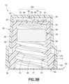
図3Aから図6を参照して、本開示の例示的な実施形態によると、安全ロッキングコネクタキャップ10は、頂壁22および側壁26を含む外側ハウジング20、頂壁32および側壁36を内部空洞38内への開口37および側壁36の内側側壁表面33の1つまたは複数のねじ山31を伴って含む内側ハウジング30、開口をシールする剥離シーリング膜(peel sealing film)40、IPA浸漬されたスポンジのような殺菌用部材50、および内側ハウジング30の開放底部のリムの表面によって構成され得るシーリング表面(sealing surface)60を含む。
Referring to Figures 3A to 6, according to an exemplary embodiment of the present disclosure, a safety
内側ハウジング30の空洞38は、剥離シーリング膜40が取り外された後または剥離シーリング膜が穿孔されたときに無針コネクタ9の先端を受け入れ、および無針コネクタ9の先端を空洞38内にねじ式に固定し、1つまたは複数のねじ山31は、例えば共に2017年1月17に提出された関連した特許文献3および特許文献4に記載されるような無針コネクタ9のハブまたは先端の嵌合機能(mating feature)と連結するのに十分である。
The
例えば図3Aおよび図3Bを参照して、本開示の実施形態の例示的な実施において、内側ハウジング30は、側壁26が側壁36を本質的に取り囲みおよび頂壁22が頂壁32を本質的に覆うように、外側ハウジング20内に配置される。安全インターフェース100は、第1の傾斜面74および第1の垂直面76を有する単数または複数の歯のような1つまたは複数の突出部72を含むラチェット機能として内側ハウジング30の頂壁32の外表面34に構成され得る第1の部分70と、第2の傾斜面84および第2の垂直面86を有する単数または複数の歯のような1つまたは複数の突出部82を含むラチェット機能として外側ハウジング20の頂部22の内表面24に構成され得る第2の部分80と、を含む。第1の垂直面76は、外表面34に対して本質的に垂直であり得、および第1の傾斜面74は、外表面34に対して鋭角であり得る。他方で、第2の垂直面86は、内表面24に対して本質的に垂直であり得、および第2の傾斜面84は、内表面24に対して鋭角であり得る。
3A and 3B, in an exemplary implementation of an embodiment of the present disclosure, the
安全インターフェース100は、外表面34は、突出部72および82が十分な接触を取り得るように内表面24と十分に近い場合を除いて、第1の部分70および第2の部分80が係合しないように構成される。
The
図3Bの例に示されるような本開示の実施形態のさらなる例示的な実施によると、内側ハウジング30に関して外側ハウジング20を固定するための保持インターフェース(retaining interface)は、例えば以下のように実施され得る。内側ハウジング30の側壁36の外表面39は、突出部(またはスカート、またはフランジ)110のような内側ハウジング保持機能を含み得、および外側ハウジング20の側壁26の内表面29は、凹部120のような外側ハウジング保持機能を含み得る。突出部110および凹部120は、例えば図5および図6の例を参照して示されるように、外側ハウジング20が内側ハウジング30上に固定されたまま内側ハウジング30に関する外側ハウジング20の回転運動を可能にするように、例えばそれぞれの突出部110の第1の接触面112および凹部120の第2の接触面122において係合するように構成される。
According to a further exemplary implementation of an embodiment of the present disclosure as shown in the example of FIG. 3B, a retaining interface for fixing the
保持インターフェースは、一方では、外側ハウジング20が内側ハウジング30に関して回転させられたときに突出部72および82は必ずしも互いに接触せず、および他方では、突出部72および82が外側ハウジング20の回転運動を内側ハウジング30に変換するために十分な接触を取るように、外側ハウジング20を内側ハウジング30に関して固定する一方で内表面24に関する外表面34の十分な軸方向運動(axial movement)可能にする。
The retention interface, on the one hand, fixes the
図3Cの例に詳細に示されるような本開示の実施形態の別のさらなる例示的な実施によると、内側ハウジング30に関して外側ハウジング20を固定するための保持インターフェースは、例えば以下のように、図3Bに示される保持インターフェースに加えてまたはその代わりに、任意選択的に実施され得る。内側ハウジング30の頂壁32の外表面34は、ラッチング突出部130のような内側ハウジング保持機能を含み得、および外側ハウジング20の頂壁22の内表面24は、対応するラッチング突出部120のような外側ハウジング保持機能を含み得る。図5および図6の例を参照して以下に示されるように、突出部130および突出部120は、例えば、突出部120の拡張された(extended)スカート122をラッチする突出部130の保持リム132によって、外側ハウジング20が内側ハウジング30上に固定される一方で内側ハウジング30に関する外側ハウジング20の回転運動を可能にするように、係合するように構成される。
According to another further exemplary implementation of an embodiment of the present disclosure as shown in detail in the example of FIG. 3C, a retention interface for securing the
例えば図4Aから図4Cを参照して、本開示の例示的な実施形態によると、安全ロッキングコネクタキャップ10の外側ハウジングは、気道通路(airway passage)、例えばヒト咽喉(human throat)にキャップが詰まった場合に、空気が通過できるように穴または開口を提供することによって、窒息の危険性を防止するようにさらに設計される
For example, with reference to Figures 4A-4C, in accordance with an exemplary embodiment of the present disclosure, the outer housing of the safety
図4Aおよび図4Bの例に示されるように、本開示の実施形態の任意の例示的な実施は、任意選択的に、外側ハウジング20の頂壁22内に、空気200が外側ハウジング20、例えば図4Bの例に図式的に示されるように外側ハウジング20の内表面と内側ハウジング30の外表面との間を通過することを可能にする、1つまたは複数の開口92、94および/または96を提供し得る。開口92、94および/または96の数、サイズおよび/または形状は、十分な通気(air passage)を保証するため、例えば安全性への懸念に対処するため、ならびに安全インターフェース100の操作および/または機能性との干渉を回避するために、変動し得る。
As shown in the examples of FIGS. 4A and 4B, any exemplary implementation of an embodiment of the present disclosure may optionally provide one or
図3Aおよび図4Aの例は、突出部110および凹部120の両方がそれぞれ内側ハウジング30および外側ハウジング20の連続的な360度の機能として任意選択的に形成される実施を図式的に示す一方で、本開示の例示的な実施形態によると、突出部110および凹部120のうちの少なくとも1つまたは両方は、部分的機能として任意選択的に形成され得る。例えば、内側ハウジング30の断面底面図によって図4Cに示されるように、連続的な360度の機能の代わりに、突出部110は、側壁36の外表面39において90度の間隔で中心位置に合わせられる多数の突出する10度の部分114を含み得る。他方で、例えば、連続的な360度の機能の代わりに、凹部120は、外側ハウジング20の断面底面図によって図4Dに示されるような1つまたは複数のギャップ124を有し得、これは、また、気道通路にキャップが詰まった場合に通気を提供することによる窒息の危険性のさらなる防止を容易にし得る。突出部110および凹部120のうちの少なくとも1つまたは両方を部分的機能として形成するとき、部分114および/またはギャップ124のサイズおよび/または形状は、外側ハウジング20が安全インターフェース100の適切な操作および/または機能性を保証するように内側ハウジング30に関して適切に構成されることを保証しながら、必要に応じておよび/または要望通りに変更され得る。
3A and 4A illustrate diagrammatically an implementation in which both the
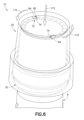
図5および図6を参照して、本開示の実施形態の例示的な実施によると、無針コネクタ9上へのキャップ10の固定は、軸方向力171の印加が、内側ハウジング30の頂部32に向かう外側ハウジング20の頂部22の軸方向運動を引き起こし、および回転力170が、外側ハウジング20の回転運動(例えば、キャップ10を無針コネクタ9上にねじ式に固定するためにおそらく必要とされるような時計回りの方向の)を引き起こすことを図式的に示す、図5に示される。頂部32に向かう頂部22の軸方向運動は、安全インターフェース100の第1の部分70と第2の部分80との間の距離を低減させ、回転力170の印加に際して第1の部分70および第2の部分80が係合することを可能にする。他方で、無針コネクタ9からのキャップ10の取り外しは、軸方向力173の印加が、内側ハウジング30の頂部32に向かう外側ハウジング20の頂部22の軸方向運動を引き起こし、および回転力172が、外側ハウジング20の回転運動(例えば、ねじ式に固定されたキャップ10を無針コネクタ9から取り外すためにおそらく必要とされるような反時計回りの方向の)を引き起こすことを図式的に示す、図6に示される。
5 and 6, in accordance with an exemplary implementation of an embodiment of the present disclosure, securing of the
図5の例に示されるように、本開示の実施形態の例示的な実施によると、力170を伴う力171の印加は、対向する(oppositely facing)本質的に垂直面76および86が接触したときに、第1の垂直面76を有する1つまたは複数の第1の突出部72とそれぞれの第2の垂直面86を有する1つまたは複数の第2の突出部82とを係合させ、内側ハウジング30が外側ハウジング20と同一回転方向に回転して、内側ハウジングを無針コネクタ9上にねじ式に回転させて、キャップねじ山31を無針コネクタ9のハブまたは先端の任意の嵌合機能と連結させて、キャップ10を無針コネクタ9上に固定するように、外側ハウジング20の回転の内側ハウジング30への変換をもたらす。
5, according to an exemplary implementation of an embodiment of the present disclosure, application of
図6の例に示されるように、本開示の実施形態の例示的な実施によると、力172を伴う力173の連続的な印加は、対向する表面74および84が接触するときに、第1の表面74を有する1つまたは複数の第1の突出部72とそれぞれの第2の表面84を有する1つまたは複数の第2の突出部82とを係合させ、内側ハウジング30が外側ハウジング20と同一回転方向に回転して、無針コネクタ9からねじ式に回転して離れて、ねじ山31を無針コネクタ9の先端またはハブの任意の嵌合機能から解放し、それによってキャップ10を無針コネクタ9から取り外すように、外側ハウジング20の回転の内側ハウジング30への伝達をもたらす。
6, according to an exemplary implementation of an embodiment of the present disclosure, the continuous application of
例示的な実施によると、無針コネクタ9に関するキャップ10の位置に基づく重力に単純に起因して、内側ハウジング30に関する外側ハウジング20の軸方向自由運動が、内側ハウジング30に向かって移動する外側ハウジング20をもたらす場合があるので、力171は、外力として印加される必要がない場合がある(または相対的に小さい大きさの力として印加される)。他方で、例えば、それぞれの表面74および84の締り嵌めによって、第1の突出部72のうちの1つまたは複数の、1つまたは複数のそれぞれの第2の突出部82との係合を保証するために、力173は、相対的により大きい大きさの外力として印加される必要がある場合がある。例えば、それぞれの表面74および84の傾斜および形状は、突出部72および82が互いに関してスリップしないが係合して外側ハウジング20の回転を内側ハウジング30に変換するように、それぞれの表面74および84の十分な締り嵌めを作り出すために必要とされる軸方向力173の量を調節するために変更され得る。例えば、向上された安全性は、任意選択的に、内側ハウジング30をねじ式に回転させて無針コネクタ9から離れさせてキャップ10を無針コネクタ9から取り外すために、第1の部分70および第2の部分80を係合させるために必要とされる軸方向力の量を増大させることによって、実現され得る。
According to an exemplary implementation, the
本開示の実施形態の例示的な実施によると、図3から図6を参照して上述された安全機能を有する外側ハウジング30は、任意選択的に、出願人の同時継続中の共に2017年1月17に提出された特許文献3および特許文献4に記載される様々な機能および設計を有する任意のまたはすべての殺菌剤(disinfectant)キャップを、例えば、図7Aおよび図7Bの例示的な例に示されるようにその中に開示される殺菌剤キャップのハウジングの外表面を修正することによって、備える実施であり得る。
According to an exemplary implementation of an embodiment of the present disclosure, the
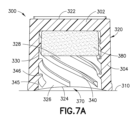
図7Aおよび図7Bを参照して、クロスねじ山(cross thread)殺菌用キャップ300は、閉鎖頂部322と、外側側壁表面320を持つ本質的に円筒形の側壁304と、無針コネクタの先端を受け入れるためのハウジング302内の内部空洞328への開口326を持つ開放底部324と、を含むハウジング302を有する。ハウジング302の側壁304によって形成された底部324は、空間370が平坦面310とキャップ300の底部324との間に存在するように、平坦ではない。内部空洞328は、アルコール浸漬された殺菌スポンジ380収容し得、および側壁304の内側側壁表面330にねじ山340を有する。キャップ300のねじ山340の直径(大径345および/または小径346)は、無針コネクタのねじ山に対応しない場合がある(may not)。本開示の例示的な実施によると、ハウジング302の外側側壁表面320は、連続的な360度の機能としてまたは1つまたは複数の突出部114として突出部110を含むように修正され得、および頂部322の外表面34は、1つまたは複数の第2の突出部72を含むように修正され得る。外側ハウジング20は、図3から図6の例に示されるような安全インターフェース100を形成するために、内側ハウジング30になるものの側壁320および頂部322に関して成形および構成され得る。
7A and 7B, a cross
本開示は、その特定の例示的な実施形態を参照して示されおよび記載されてきたが、当業者には、形の上でのおよび詳細における様々な変更が、本開示の実施形態の精神および範囲から逸脱することなく、本明細書においてなされてもよいことが理解されよう。例えば、殺菌スポンジは、任意の適当な殺菌用または他の特定用途向け(application-specific)物質を含み得、および任意の適当な材料製であり得る。また、キャップの内側および/または外側ハウジングは、シングルショット成形され得、または他の適当なプロセスにより製造され得る。なおさらに、上述されおよび図面の図に示されるような本開示の実施形態の任意の例示的な実施の機能または要素のうちの任意のものは、本開示の実施形態の精神および範囲から逸脱することなく当業者によって容易に評価されるであろうように、個々にまたは任意の組み合わせ(単数または複数)で実施され得る。 Although the present disclosure has been shown and described with reference to certain exemplary embodiments thereof, those skilled in the art will understand that various changes in form and detail may be made herein without departing from the spirit and scope of the embodiments of the present disclosure. For example, the germicidal sponge may include any suitable germicidal or other application-specific substance and may be made of any suitable material. Also, the inner and/or outer housing of the cap may be single-shot molded or manufactured by other suitable processes. Still further, any of the features or elements of any exemplary implementation of the embodiments of the present disclosure as described above and shown in the drawing figures may be implemented individually or in any combination(s) as would be readily appreciated by a person skilled in the art without departing from the spirit and scope of the embodiments of the present disclosure.
加えて、含まれる図面の図は、本開示の特定の例示的な実施形態の実施の非限定的な例をさらに説明し、およびそれに関連するテクノロジーの説明を助ける。上述されたものとは異なる図面に提供される任意の特定のまたは相対的な寸法または測定値は、例示的であり、および開示の関連分野における熟練工によって理解されるような発明の設計または方法論の範囲または内容を限定することが意図されるものではない。 In addition, the included drawing figures further illustrate non-limiting examples of implementation of certain exemplary embodiments of the present disclosure and aid in the description of the technology associated therewith. Any specific or relative dimensions or measurements provided in the drawings other than those described above are exemplary and are not intended to limit the scope or content of the inventive designs or methodologies as understood by a skilled artisan in the relevant art of the disclosure.
本開示の他の目的、利点および利点および顕著な特徴は、添付される図面の図と併せて、本開示の例示的な実施形態を開示する、提供される詳細から当業者にとって明らかになるであろう。 Other objects, advantages and benefits and salient features of the present disclosure will become apparent to those skilled in the art from the details provided, which, taken in conjunction with the accompanying drawing figures, disclose exemplary embodiments of the present disclosure.
Claims (17)
第1の頂壁、
本質的に円筒形の第1の側壁であって、前記第1の頂壁および前記第1の側壁は前記内側ハウジング内に内部空洞を形成し、前記第1の頂壁は前記内部空洞の閉鎖頂部を形成する、第1の側壁、
前記第1の側壁によって形成され、無針コネクタのハブを受け入れるための前記内側ハウジング内の前記内部空洞への開口を有する、開放底部、および
前記第1の側壁の内側側壁表面の少なくとも1つのキャップねじ山であって、前記無針コネクタの前記ハブの嵌合機能と連結するのに十分である、少なくとも1つのキャップねじ山、
を含む、内側ハウジングと、
外側ハウジングであって、
前記第1の頂壁より上に構成される第2の頂壁、および
前記第1の側壁を本質的に取り囲むように構成される本質的に円筒形の第2の側壁、
を含む、外側ハウジングと、
安全インターフェースであって、
前記第1の頂壁の外表面に構成される第1の部分、および
前記第2の頂壁の内表面に構成される第2の部分
を含む安全インターフェースと、
を含み、
前記外側ハウジングの前記第2の頂壁は、前記第2の頂壁を通って延び空気が前記外側ハウジングを通過することを可能にする少なくとも1つの開口を含み、
前記安全インターフェースは、前記第1の頂壁および前記第2の頂壁が互いに向かって付勢されならびに前記第1の部分および前記第2の部分が係合したときに、前記外側ハウジングの回転運動を、同一回転方向の前記内側ハウジングの回転運動に変換し、および
前記外側ハウジングは、前記第1の頂壁および前記第2の頂壁が前記第1の部分および前記第2の部分が互いと係合しないように互いに向かって付勢されないときに、前記内側ハウジングに関して回転することが可能となっていることを特徴とするコネクタキャップ。 An inner housing comprising:
A first top wall;
a first sidewall that is essentially cylindrical, said first top wall and said first sidewall forming an interior cavity within said inner housing, said first top wall forming a closed top of said interior cavity;
an open bottom defined by the first sidewall having an opening to the internal cavity within the inner housing for receiving a hub of a needleless connector; and at least one cap thread on an inner sidewall surface of the first sidewall sufficient to interlock with a mating feature of the hub of the needleless connector.
an inner housing including:
An outer housing comprising:
a second top wall configured above the first top wall; and an essentially cylindrical second side wall configured to essentially surround the first side wall.
an outer housing including:
A safety interface, comprising:
a safety interface including a first portion configured on an outer surface of the first top wall, and a second portion configured on an inner surface of the second top wall;
Including,
the second top wall of the outer housing includes at least one opening extending through the second top wall to allow air to pass through the outer housing ;
the safety interface converts rotational motion of the outer housing into rotational motion of the inner housing in the same rotational direction when the first and second top walls are biased toward one another and the first and second portions are engaged; and
The connector cap is characterized in that the outer housing is capable of rotating relative to the inner housing when the first top wall and the second top wall are not biased toward each other so that the first portion and the second portion do not engage with each other .
前記第2の突出部は、前記第2の頂壁の前記内表面に対して本質的に垂直な第2の垂直面および前記第2の頂壁の前記内表面に対して鋭角な第2の傾斜面を含むことを特徴とする請求項2に記載のコネクタキャップ。 3. The connector cap of claim 2, wherein the first protrusion includes a first vertical surface essentially perpendicular to the outer surface of the first top wall and a first inclined surface at an acute angle to the outer surface of the first top wall, and the second protrusion includes a second vertical surface essentially perpendicular to the inner surface of the second top wall and a second inclined surface at an acute angle to the inner surface of the second top wall.
前記外側ハウジングは、外側ハウジング保持機能を含み、
前記内側ハウジング保持機能および前記外側ハウジング保持機能は、前記外側ハウジングを前記内側ハウジング上に固定するように係合しおよび前記安全インターフェースの前記第1の部分および前記安全インターフェースの前記第2の部分が係合されていないときに前記内側ハウジングに関する前記外側ハウジングの回転運動を可能にするように構成されていることを特徴とする請求項1から4のいずれか一項に記載のコネクタキャップ。 the inner housing includes an inner housing retention feature, and the outer housing includes an outer housing retention feature;
5. The connector cap of claim 1, wherein the inner housing retention feature and the outer housing retention feature are configured to engage to securely fasten the outer housing onto the inner housing and to allow rotational movement of the outer housing relative to the inner housing when the first portion of the safety interface and the second portion of the safety interface are disengaged.
前記外側ハウジング保持機能は、前記外側ハウジングの前記第2の側壁の内表面に凹部を含み、
前記第1の側壁の前記外表面の前記突出部および前記第2の側壁の前記内表面の前記凹部は、前記外側ハウジングを前記内側ハウジング上に固定するように係合するように構成されることを特徴とする請求項5に記載のコネクタキャップ。 the inner housing retention feature comprises a protrusion on an outer surface of the first side wall of the inner housing; and the outer housing retention feature comprises a recess on an inner surface of the second side wall of the outer housing.
6. The connector cap of claim 5, wherein the protrusion on the outer surface of the first side wall and the recess on the inner surface of the second side wall are configured to engage to secure the outer housing onto the inner housing .
前記外側ハウジング保持機能は、前記外側ハウジングの前記第2の頂壁の内表面に第2のラッチング突出部を含み、
前記第1のラッチング突出部および前記第2のラッチング突出部は、前記外側ハウジングを前記内側ハウジング上にラッチするように構成されることを特徴とする請求項5に記載のコネクタキャップ。 the inner housing retention feature includes a first latching protrusion on an outer surface of the first top wall of the inner housing, and the outer housing retention feature includes a second latching protrusion on an inner surface of the second top wall of the outer housing;
The connector cap of claim 5 , wherein the first latching protrusion and the second latching protrusion are configured to latch the outer housing onto the inner housing.
前記外側ハウジングの前記回転運動を引き起こし、および
前記安全インターフェースの前記第2の部分を前記安全インターフェースの前記第1の部分と係合させて、前記外側ハウジングの前記回転運動を前記内側ハウジングの前記回転運動に変換して、前記内側ハウジングをねじ式に回転させて、前記キャップねじ山を前記無針コネクタの前記ハブの前記嵌合機能と連結させることを特徴とする請求項1から8のいずれか一項に記載のコネクタキャップ。 The application of a rotational force to the outer housing includes:
9. The connector cap of claim 1, further comprising: causing the rotational movement of the outer housing; and engaging the second portion of the safety interface with the first portion of the safety interface to convert the rotational movement of the outer housing to the rotational movement of the inner housing, thereby threadably rotating the inner housing to couple the cap threads with the mating feature of the hub of the needleless connector.
前記外側ハウジングへの回転力の印加は、
前記外側ハウジングの前記回転運動を引き起こし、および
前記安全インターフェースの前記第2の部分を前記安全インターフェースの前記第1の部分と係合させ続けて、前記外側ハウジングの前記回転運動を前記内側ハウジングの前記回転運動に変換して、前記内側ハウジングをねじ式に回転させて、前記キャップねじ山を前記無針コネクタの前記ハブの前記嵌合機能から取り外すことを特徴とする請求項1から8のいずれか一項に記載のコネクタキャップ。 The continued application of an axial force to the outer housing in the direction of the inner housing causes the second portion of the safety interface to engage with the first portion of the safety interface in an interference fit; and the application of a rotational force to the outer housing causes
9. The connector cap of claim 1, further comprising: causing the rotational movement of the outer housing; and continuing to engage the second portion of the safety interface with the first portion of the safety interface to convert the rotational movement of the outer housing into the rotational movement of the inner housing to threadably rotate the inner housing and disengage the cap threads from the mating feature of the hub of the needleless connector .
前記キャップの使用前に前記内部空洞内の前記スポンジをシールするための、前記内部空洞の前記開口をシールする取り外し可能カバー、
をさらに含み、
前記キャップねじ山は、前記無針コネクタの前記嵌合機能に対応しないことを特徴とする請求項1から11のいずれか一項に記載のコネクタキャップ。 a germicidal sponge configured within the internal cavity; and a removable cover sealing the opening of the internal cavity for sealing the sponge within the internal cavity prior to use of the cap.
Further comprising:
The connector cap of any one of claims 1 to 11 , wherein the cap threads do not correspond to the mating features of the needleless connector.
前記無針コネクタの前記嵌合機能との前記連結を容易にするために前記キャップねじ山の少なくとも部分に形成された少なくとも1つの連結部分と、
前記無針コネクタの前記嵌合機能と係合しない少なくとも1つの非係合部分と、
を含むことを特徴とする請求項12に記載のコネクタキャップ。 The cap threads are
at least one coupling portion formed on at least a portion of the cap thread to facilitate the coupling with the mating feature of the needleless connector;
at least one non-engaging portion that does not engage with the mating feature of the needleless connector;
The connector cap of claim 12 , comprising:
第1の開始ねじ山パスであって、大外形、小外形、ピッチ、および第1のねじ山部分輪郭を有する、第1の開始ねじ山パス、
少なくとも1つの第2の開始ねじ山パスであって、大外形、小外形、ピッチ、および第2のねじ山部分輪郭を有する、第2の開始ねじ山パス、
を含み、
前記第1のねじ山部分輪郭および前記第2のねじ山部分輪郭は、異なることを特徴とする請求項12に記載のコネクタキャップ。 The cap threads are
a first starting thread path having a major profile, a minor profile, a pitch, and a first thread portion profile;
at least one second starting thread path having a major profile, a minor profile, a pitch, and a second thread portion profile;
Including,
The connector cap of claim 12 , wherein the first thread portion profile and the second thread portion profile are different.
Applications Claiming Priority (4)
| Application Number | Priority Date | Filing Date | Title |
|---|---|---|---|
| US201762488266P | 2017-04-21 | 2017-04-21 | |
| US62/488,266 | 2017-04-21 | ||
| PCT/US2018/028247 WO2018195241A1 (en) | 2017-04-21 | 2018-04-19 | Connector cap |
| JP2019556848A JP7104064B2 (en) | 2017-04-21 | 2018-04-19 | Connector cap |
Related Parent Applications (1)
| Application Number | Title | Priority Date | Filing Date |
|---|---|---|---|
| JP2019556848A Division JP7104064B2 (en) | 2017-04-21 | 2018-04-19 | Connector cap |
Publications (2)
| Publication Number | Publication Date |
|---|---|
| JP2022125291A JP2022125291A (en) | 2022-08-26 |
| JP7586861B2 true JP7586861B2 (en) | 2024-11-19 |
Family
ID=63853010
Family Applications (2)
| Application Number | Title | Priority Date | Filing Date |
|---|---|---|---|
| JP2019556848A Active JP7104064B2 (en) | 2017-04-21 | 2018-04-19 | Connector cap |
| JP2022109851A Active JP7586861B2 (en) | 2017-04-21 | 2022-07-07 | Connector cap |
Family Applications Before (1)
| Application Number | Title | Priority Date | Filing Date |
|---|---|---|---|
| JP2019556848A Active JP7104064B2 (en) | 2017-04-21 | 2018-04-19 | Connector cap |
Country Status (8)
| Country | Link |
|---|---|
| US (1) | US12151077B2 (en) |
| EP (1) | EP3612266B1 (en) |
| JP (2) | JP7104064B2 (en) |
| CN (3) | CN113877057B (en) |
| AU (1) | AU2018256404B2 (en) |
| CA (1) | CA3056443A1 (en) |
| MX (1) | MX2019011979A (en) |
| WO (1) | WO2018195241A1 (en) |
Families Citing this family (15)
| Publication number | Priority date | Publication date | Assignee | Title |
|---|---|---|---|---|
| US8491016B2 (en) | 2009-03-16 | 2013-07-23 | Colder Products Company | Aseptic coupling devices |
| JP7104064B2 (en) * | 2017-04-21 | 2022-07-20 | ベクトン・ディキンソン・アンド・カンパニー | Connector cap |
| WO2018237122A1 (en) | 2017-06-22 | 2018-12-27 | Becton, Dickinson And Company | CONNECTOR PLUG HAVING A SAFETY ORIFICE |
| USD932006S1 (en) | 2018-11-21 | 2021-09-28 | Regeneron Pharmaceuticals, Inc. | Auto-injector cap |
| US12115359B2 (en) * | 2018-07-20 | 2024-10-15 | Shl Medical Ag | Medicament delivery device |
| AU2019387090B2 (en) * | 2018-11-30 | 2025-07-24 | Becton, Dickinson And Company | Rotary activated universal connector cap |
| JP2022546706A (en) | 2019-08-27 | 2022-11-07 | コルダー プロダクツ カンパニー | Disposable Genderless Aseptic Fluid Coupling |
| CN111135453B (en) * | 2020-03-06 | 2024-08-27 | 安徽天康医疗科技股份有限公司 | Open-and-destroy cap for gastrointestinal tract application small-caliber connector |
| US11890446B2 (en) * | 2020-04-17 | 2024-02-06 | Becton, Dickinson And Company | Cap for male and female threaded fittings |
| KR102359511B1 (en) * | 2020-05-29 | 2022-02-09 | 한국전력공사 | Insulation cap for insulating plug |
| IL300492A (en) | 2020-08-07 | 2023-04-01 | Dak Scient Inc | Tamper resistant and medical connector devices |
| IT202100003320A1 (en) * | 2021-02-15 | 2022-08-15 | Platinum Pharma Service S R L S | SYRINGE CAP WITH LUER-LOCK ATTACHMENT |
| US20230398344A1 (en) * | 2022-06-10 | 2023-12-14 | Quest Medical, Inc. | Sealing device for needleless connectors |
| WO2024047457A1 (en) * | 2022-08-29 | 2024-03-07 | Solventum Intellectual Properties Company | Protection device for medical article |
| WO2024047456A1 (en) * | 2022-08-29 | 2024-03-07 | Solventum Intellectual Properties Company | Protection device for medical article |
Citations (6)
| Publication number | Priority date | Publication date | Assignee | Title |
|---|---|---|---|---|
| JP2004001901A (en) | 2003-08-29 | 2004-01-08 | Sakura Color Prod Corp | Cap for paint tube |
| US20050077262A1 (en) | 2003-10-09 | 2005-04-14 | Elesa S.P.A. | Vandal resistant locking cap with limited tightening torque |
| US20080019889A1 (en) | 2006-07-21 | 2008-01-24 | Rogers Bobby E | Medical implement cleaning device |
| JP2014513569A (en) | 2011-02-18 | 2014-06-05 | イベラ・メディカル・コーポレイション | Medical device cleaning system |
| CN103990226A (en) | 2014-06-10 | 2014-08-20 | 倪新华 | Exhaust bacterium blocking cap |
| JP2016511111A (en) | 2013-03-14 | 2016-04-14 | エクセルシオール・メディカル・コーポレイションExcelsior Medical Corporation | Disinfection end cap |
Family Cites Families (32)
| Publication number | Priority date | Publication date | Assignee | Title |
|---|---|---|---|---|
| US3435978A (en) * | 1967-01-23 | 1969-04-01 | John C Wittwer | Bottle cap with interlocking threads |
| US3650426A (en) * | 1970-03-30 | 1972-03-21 | V C A Corp | Safety cap |
| JPS5153949Y2 (en) * | 1971-12-25 | 1976-12-23 | ||
| US4697715A (en) * | 1986-09-02 | 1987-10-06 | Waynesboro Textiles | Anticocking high torque removal closure assembly |
| JPH0712061Y2 (en) * | 1988-05-21 | 1995-03-22 | 三菱鉛筆株式会社 | Caps for writing instruments |
| JPH039879U (en) * | 1989-06-15 | 1991-01-30 | ||
| US5292020A (en) * | 1993-05-13 | 1994-03-08 | Phoenix Closures, Inc. | Closure with anti-backoff feature |
| DE9419630U1 (en) * | 1994-12-09 | 1995-02-02 | Fresenius AG, 61352 Bad Homburg | Device for closing a line |
| US5651776A (en) | 1995-03-22 | 1997-07-29 | Angiodynamics, Inc. | Luer-type connector |
| JP2941204B2 (en) | 1995-07-03 | 1999-08-25 | アルシン・メディカル・インコーポレーテッド | Medical device cap |
| US6095353A (en) * | 1998-12-11 | 2000-08-01 | Christopher Tarantino | Slide lock child resistant safety cap |
| US20050165351A1 (en) | 2004-01-28 | 2005-07-28 | Tamagni Henry A.Jr. | No choke cover cap |
| US7497484B2 (en) * | 2004-08-11 | 2009-03-03 | Smiths Medical Asd, Inc. | Medical coupling system |
| US7660851B2 (en) | 2005-07-06 | 2010-02-09 | Microsoft Corporation | Meetings near me |
| US8740864B2 (en) | 2005-11-17 | 2014-06-03 | Becton, Dickinson And Company | Patient fluid line access valve antimicrobial cap/cleaner |
| US8167847B2 (en) * | 2006-06-22 | 2012-05-01 | Excelsior Medical Corporation | Antiseptic cap and antiseptic cap equipped plunger and syringe barrel assembly |
| ITBS20060190A1 (en) * | 2006-10-27 | 2008-04-28 | Guala Pack Spa | CAP FOR CONTAINER WITH SEALED GUARANTEE |
| US20080147047A1 (en) * | 2006-12-18 | 2008-06-19 | Sage Products, Inc. | Needleless Hub Disinfection Device and Method |
| US8523831B2 (en) | 2009-10-30 | 2013-09-03 | Catheter Connections, Inc. | Disinfecting caps having sealing features and related systems and methods |
| US8177761B2 (en) * | 2007-01-16 | 2012-05-15 | The University Of Utah Research Foundation | Assembly for cleaning luer connectors |
| US20090028750A1 (en) | 2007-07-23 | 2009-01-29 | Ryan Dana Wm | Cleaning and Disinfection Swabbing Device for Needle-Free Intravenous (IV) Connectors |
| CA2717754C (en) * | 2008-03-04 | 2017-06-06 | Infusion Innovations, Inc. | Devices, assemblies, and methods for controlling fluid flow |
| JP2012528689A (en) | 2009-06-01 | 2012-11-15 | イベラ・メディカル・コーポレイション | Cleaning device for medical equipment with friction-based fitting |
| US20110314619A1 (en) | 2010-06-23 | 2011-12-29 | Medical Components, Inc. | Cleaner for Medical Device |
| WO2013066285A1 (en) * | 2011-11-02 | 2013-05-10 | Psi Medical Catheter Care,Llc | Apparatus for sterilizing a tubular medical line port |
| US8443999B1 (en) | 2012-04-16 | 2013-05-21 | Robert C. Reinders | Cap, cap/container combination |
| WO2014106047A1 (en) | 2012-12-28 | 2014-07-03 | Porex Corporation | Sintered porous polymeric caps and vents for components of medical devices |
| US9399125B2 (en) | 2013-02-13 | 2016-07-26 | Becton, Dickinson And Company | Needleless connector and access port disinfection cleaner and antimicrobial protection cap |
| US8721619B1 (en) * | 2013-03-06 | 2014-05-13 | Nellin Medical Devices, LLC | Safety device |
| US9144672B2 (en) * | 2013-03-13 | 2015-09-29 | Carefusion 303, Inc. | Needleless connector with compressible valve |
| US9907617B2 (en) | 2013-03-15 | 2018-03-06 | 3M Innovative Properties Company | Medical implement cleaning device |
| JP7104064B2 (en) * | 2017-04-21 | 2022-07-20 | ベクトン・ディキンソン・アンド・カンパニー | Connector cap |
-
2018
- 2018-04-19 JP JP2019556848A patent/JP7104064B2/en active Active
- 2018-04-19 AU AU2018256404A patent/AU2018256404B2/en active Active
- 2018-04-19 CA CA3056443A patent/CA3056443A1/en active Pending
- 2018-04-19 MX MX2019011979A patent/MX2019011979A/en unknown
- 2018-04-19 US US15/957,208 patent/US12151077B2/en active Active
- 2018-04-19 EP EP18788167.7A patent/EP3612266B1/en active Active
- 2018-04-19 WO PCT/US2018/028247 patent/WO2018195241A1/en not_active Ceased
- 2018-04-20 CN CN202111169620.4A patent/CN113877057B/en active Active
- 2018-04-20 CN CN201810356715.9A patent/CN108736176B/en active Active
- 2018-04-20 CN CN201820566338.7U patent/CN208299057U/en active Active
-
2022
- 2022-07-07 JP JP2022109851A patent/JP7586861B2/en active Active
Patent Citations (6)
| Publication number | Priority date | Publication date | Assignee | Title |
|---|---|---|---|---|
| JP2004001901A (en) | 2003-08-29 | 2004-01-08 | Sakura Color Prod Corp | Cap for paint tube |
| US20050077262A1 (en) | 2003-10-09 | 2005-04-14 | Elesa S.P.A. | Vandal resistant locking cap with limited tightening torque |
| US20080019889A1 (en) | 2006-07-21 | 2008-01-24 | Rogers Bobby E | Medical implement cleaning device |
| JP2014513569A (en) | 2011-02-18 | 2014-06-05 | イベラ・メディカル・コーポレイション | Medical device cleaning system |
| JP2016511111A (en) | 2013-03-14 | 2016-04-14 | エクセルシオール・メディカル・コーポレイションExcelsior Medical Corporation | Disinfection end cap |
| CN103990226A (en) | 2014-06-10 | 2014-08-20 | 倪新华 | Exhaust bacterium blocking cap |
Also Published As
| Publication number | Publication date |
|---|---|
| CN108736176A (en) | 2018-11-02 |
| JP2022125291A (en) | 2022-08-26 |
| AU2018256404A1 (en) | 2019-10-24 |
| EP3612266C0 (en) | 2023-12-20 |
| JP7104064B2 (en) | 2022-07-20 |
| MX2019011979A (en) | 2019-11-08 |
| AU2018256404B2 (en) | 2024-01-04 |
| US20180304067A1 (en) | 2018-10-25 |
| CN108736176B (en) | 2021-10-29 |
| EP3612266A1 (en) | 2020-02-26 |
| CN208299057U (en) | 2018-12-28 |
| EP3612266A4 (en) | 2021-01-13 |
| CN113877057A (en) | 2022-01-04 |
| CN113877057B (en) | 2023-10-13 |
| JP2020517342A (en) | 2020-06-18 |
| CA3056443A1 (en) | 2018-10-25 |
| EP3612266B1 (en) | 2023-12-20 |
| BR112019021955A2 (en) | 2020-05-05 |
| US12151077B2 (en) | 2024-11-26 |
| WO2018195241A1 (en) | 2018-10-25 |
Similar Documents
| Publication | Publication Date | Title |
|---|---|---|
| JP7586861B2 (en) | Connector cap | |
| JP7648577B2 (en) | Connector cap with safety vent | |
| US12186523B2 (en) | Disinfection cap for IV needleless connectors | |
| JP7387735B2 (en) | Rotary actuated universal connector cap | |
| CN113195037A (en) | Double-end disinfection cap for plug valve | |
| BR112019027546B1 (en) | CONNECTOR CAP WITH SAFETY VENT | |
| BR112019021955B1 (en) | CONNECTOR COVER |
Legal Events
| Date | Code | Title | Description |
|---|---|---|---|
| A521 | Request for written amendment filed |
Free format text: JAPANESE INTERMEDIATE CODE: A523 Effective date: 20220808 |
|
| A621 | Written request for application examination |
Free format text: JAPANESE INTERMEDIATE CODE: A621 Effective date: 20220808 |
|
| A977 | Report on retrieval |
Free format text: JAPANESE INTERMEDIATE CODE: A971007 Effective date: 20230630 |
|
| A131 | Notification of reasons for refusal |
Free format text: JAPANESE INTERMEDIATE CODE: A131 Effective date: 20230801 |
|
| A521 | Request for written amendment filed |
Free format text: JAPANESE INTERMEDIATE CODE: A523 Effective date: 20231101 |
|
| A131 | Notification of reasons for refusal |
Free format text: JAPANESE INTERMEDIATE CODE: A131 Effective date: 20240206 |
|
| A601 | Written request for extension of time |
Free format text: JAPANESE INTERMEDIATE CODE: A601 Effective date: 20240507 |
|
| A521 | Request for written amendment filed |
Free format text: JAPANESE INTERMEDIATE CODE: A523 Effective date: 20240708 |
|
| TRDD | Decision of grant or rejection written | ||
| A01 | Written decision to grant a patent or to grant a registration (utility model) |
Free format text: JAPANESE INTERMEDIATE CODE: A01 Effective date: 20241008 |
|
| A61 | First payment of annual fees (during grant procedure) |
Free format text: JAPANESE INTERMEDIATE CODE: A61 Effective date: 20241107 |
|
| R150 | Certificate of patent or registration of utility model |
Ref document number: 7586861 Country of ref document: JP Free format text: JAPANESE INTERMEDIATE CODE: R150 |