JP7586855B2 - Dental treatment equipment - Google Patents

Dental treatment equipment Download PDF

Info

Publication number
JP7586855B2
JP7586855B2 JP2022095571A JP2022095571A JP7586855B2 JP 7586855 B2 JP7586855 B2 JP 7586855B2 JP 2022095571 A JP2022095571 A JP 2022095571A JP 2022095571 A JP2022095571 A JP 2022095571A JP 7586855 B2 JP7586855 B2 JP 7586855B2
Authority
JP
Japan
Prior art keywords
cutting tool
drive
root canal
load
control unit
Prior art date
Legal status (The legal status is an assumption and is not a legal conclusion. Google has not performed a legal analysis and makes no representation as to the accuracy of the status listed.)
Active
Application number
JP2022095571A
Other languages
Japanese (ja)
Other versions
JP2023182143A (en
Inventor
恭平 加藤
Current Assignee (The listed assignees may be inaccurate. Google has not performed a legal analysis and makes no representation or warranty as to the accuracy of the list.)
J Morita Manufaturing Corp
Original Assignee
J Morita Manufaturing Corp
Priority date (The priority date is an assumption and is not a legal conclusion. Google has not performed a legal analysis and makes no representation as to the accuracy of the date listed.)
Filing date
Publication date
Application filed by J Morita Manufaturing Corp filed Critical J Morita Manufaturing Corp
Priority to JP2022095571A priority Critical patent/JP7586855B2/en
Publication of JP2023182143A publication Critical patent/JP2023182143A/en
Application granted granted Critical
Publication of JP7586855B2 publication Critical patent/JP7586855B2/en
Active legal-status Critical Current
Anticipated expiration legal-status Critical

Links

Images

Landscapes

  • Dental Tools And Instruments Or Auxiliary Dental Instruments (AREA)

Description

本開示は、ハンドピースを備えた歯科用治療装置に関し、特に、歯の根管(以下、単に根管ともいう)の内壁を切削拡大する歯科用治療装置に関する。 This disclosure relates to a dental treatment device equipped with a handpiece, and in particular to a dental treatment device that cuts and enlarges the inner wall of a tooth's root canal (hereinafter simply referred to as the root canal).

歯科治療において、根管を切削拡大する治療が行われることがある。当該治療には、ハンドピースのヘッド部にファイル或いはリーマと称される切削工具を取付けた歯科用治療装置が用いられる。歯科用治療装置は、モータなどの駆動部で切削工具を回転駆動することで根管を切削拡大している。切削工具には、例えば、時計回り方向の回転駆動で切削を行うように刃が形成されている。そのため、歯科用治療装置は、切削工具を時計回り方向に回転駆動すると根管壁に切削工具の刃が食い込み根管を切削拡大することができる。 Dental treatment may involve cutting and enlarging the root canal. For this treatment, a dental treatment device is used that has a cutting tool called a file or reamer attached to the head of a handpiece. The dental treatment device cuts and enlarges the root canal by rotating the cutting tool with a drive unit such as a motor. The cutting tool has a blade that cuts when rotated clockwise, for example. Therefore, when the dental treatment device rotates the cutting tool clockwise, the blade of the cutting tool bites into the root canal wall, cutting and enlarging the root canal.

国際公開第2012/164875号(特許文献1)に記載の歯科用治療装置では、一定時間毎にモータの回転方向を反転させて、切削工具の回転駆動を一定時間毎に正転駆動と逆転駆動とを繰り返すツイスト駆動を行っている。ここで、歯科用治療装置において、時計回り方向の回転駆動を正転駆動、反時計回り方向の回転駆動を逆転駆動とする。 In the dental treatment device described in International Publication No. 2012/164875 (Patent Document 1), the rotation direction of the motor is reversed at regular intervals to perform twist drive, in which the cutting tool is rotated in a forward and reverse direction repeatedly at regular intervals. Here, in the dental treatment device, clockwise rotation is referred to as forward drive, and counterclockwise rotation is referred to as reverse drive.

国際公開第2012/164875号International Publication No. 2012/164875

歯科用治療装置は、正転駆動で根管を切削する場合、切削工具を所定の回転速度で回転駆動させている。そのため、歯科用治療装置は、停止状態から所定の回転速度に達するまでの時間を短くするほど切削効率が高くなる。しかし、停止状態から所定の回転速度に達するまでの時間を短くするには、回転加速度を速くする必要があるが、回転加速度を速くすると駆動部であるモータの振動が大きくなる。逆に、歯科用治療装置は、停止状態から所定の回転速度に達するまでの時間を長くすると、モータの振動は小さくなるが切削効率は低下する。 When cutting a root canal with forward drive, the dental treatment device rotates and drives the cutting tool at a predetermined rotational speed. Therefore, the shorter the time it takes for the dental treatment device to reach the predetermined rotational speed from a stopped state, the higher the cutting efficiency. However, to shorten the time it takes for the dental treatment device to reach the predetermined rotational speed from a stopped state, it is necessary to increase the rotational acceleration, but increasing the rotational acceleration increases the vibration of the motor, which is the drive unit. Conversely, if the time it takes for the dental treatment device to reach the predetermined rotational speed from a stopped state is increased, the vibration of the motor decreases but the cutting efficiency decreases.

つまり、歯科用治療装置では、切削効率を高めるとモータの振動が大きくなり、逆に切削効率を低下させるとモータの振動は小さくなる。そのため、切削効率とモータの振動との間には二律背反の関係が存在し、歯科用治療装置では、モータの振動を抑えつつ、切削効率の良い切削工具の回転駆動を行うことは困難であった。特に、特許文献1のようなツイスト駆動をする歯科用治療装置では、正転駆動と逆転駆動とを繰り返して切削工具の回転駆動を行うため切削工具5の回転の加速、減速を繰り返し行う必要から、モータの振動を抑えつつ、切削効率の良い切削工具の回転駆動を行うことは困難であった。 In other words, in dental treatment devices, increasing the cutting efficiency increases the motor vibration, and conversely, decreasing the cutting efficiency decreases the motor vibration. Therefore, there is a trade-off between cutting efficiency and motor vibration, and in dental treatment devices, it has been difficult to perform rotational driving of the cutting tool with good cutting efficiency while suppressing motor vibration. In particular, in dental treatment devices with twist drive such as those in Patent Document 1, the cutting tool is rotated by repeatedly driving forward and reverse, so it is necessary to repeatedly accelerate and decelerate the rotation of the cutting tool 5, making it difficult to perform rotational driving of the cutting tool with good cutting efficiency while suppressing motor vibration.

本開示は、上記問題点を解決するためになされたものであり、駆動部の振動を抑えつつ、切削効率の良い切削工具の回転駆動を行うことができる歯科用治療装置を提供することを目的とする。 The present disclosure has been made to solve the above problems, and aims to provide a dental treatment device that can rotate and drive a cutting tool with good cutting efficiency while suppressing vibration in the drive unit.

本開示に係る歯科用治療装置は、歯牙の根管を治療する歯科用治療装置である。歯科用治療装置は、ハンドピースのヘッド部に保持した、根管を切削するための切削工具を回転駆動する駆動部と、切削工具を回転駆動する駆動部を制御する制御部と、切削工具に加わる負荷を検出する負荷検出部と、を備える。制御部は、負荷検出部で検出する切削工具に加わる負荷が第2基準負荷以上である場合、切削工具が切削対象物を切削する正転駆動、または正転の駆動量が大きいツイスト駆動を、逆転駆動、または逆転の駆動量が大きいツイスト駆動に切り替え、負荷検出部で検出する切削工具に加わる負荷が第2基準負荷未満である場合、起動する期間および停止させる期間の切削工具の回転加速度の大きさを第3値とし、負荷検出部で検出する切削工具に加わる負荷が第2基準負荷以上である場合、起動する期間および停止させる期間の切削工具の回転加速度の大きさを第3値より大きい第4値として駆動部を制御する The dental treatment device according to the present disclosure is a dental treatment device for treating a root canal of a tooth. The dental treatment device includes a drive unit that rotates and drives a cutting tool for cutting a root canal held in a head unit of a handpiece, a control unit that controls the drive unit that rotates and drives the cutting tool, and a load detection unit that detects a load applied to the cutting tool. When the load applied to the cutting tool detected by the load detection unit is equal to or greater than a second reference load, the control unit switches the forward drive or twist drive with a large forward drive amount for the cutting tool to cut a cutting object to a reverse drive or twist drive with a large reverse drive amount, and controls the drive unit to set the magnitude of the rotational acceleration of the cutting tool during the start and stop periods to a third value when the load applied to the cutting tool detected by the load detection unit is less than the second reference load, and to set the magnitude of the rotational acceleration of the cutting tool during the start and stop periods to a fourth value greater than the third value when the load applied to the cutting tool detected by the load detection unit is equal to or greater than the second reference load .

本発明に係る別の歯科用治療装置は、歯牙の根管を治療する歯科用治療装置である。歯科用治療装置は、ハンドピースのヘッド部に保持した切削工具を回転駆動する駆動部と、切削工具を回転駆動する駆動部を制御する制御部と、電気的根管長測定で得られる切削工具の先端の根管内での位置を検出する位置検出部と、を備える。制御部は、位置検出部で検出した切削工具の先端の位置が基準位置より根尖に近い場合、起動する期間および停止させる期間の切削工具の回転加速度を、基準位置より根尖から遠い場合に比べて大きくして駆動部を制御する Another dental treatment device according to the present invention is a dental treatment device for treating a root canal of a tooth. The dental treatment device includes a drive unit that rotates and drives a cutting tool held in a head unit of a handpiece, a control unit that controls the drive unit that rotates and drives the cutting tool, and a position detection unit that detects the position of the tip of the cutting tool in the root canal obtained by electrical root canal length measurement. When the position of the tip of the cutting tool detected by the position detection unit is closer to the root apex than a reference position, the control unit controls the drive unit by increasing the rotational acceleration of the cutting tool during the start period and the stop period compared to when the tip is farther from the root apex than the reference position .

本開示に係る歯科用治療装置は、切削工具に加わる負荷に応じて、切削工具の回転加速度を変更するように駆動部を制御するので、駆動部の振動を抑えつつ、切削効率の良い切削工具の回転駆動を行うことができる。 The dental treatment device disclosed herein controls the drive unit to change the rotational acceleration of the cutting tool according to the load applied to the cutting tool, so that the cutting tool can be rotated with good cutting efficiency while suppressing vibration in the drive unit.

実施の形態1に係る根管治療器の構成を示す概略図である。1 is a schematic diagram showing a configuration of a root canal treating instrument according to a first embodiment. FIG. 実施の形態1に係る根管治療器の機能の構成を示すブロック図である。2 is a block diagram showing the functional configuration of the root canal treating device according to the first embodiment; FIG. 実施の形態1に係る根管治療器の回路構成を示す回路図である。1 is a circuit diagram showing a circuit configuration of a root canal treating device according to a first embodiment. FIG. 切削工具の回転方向を示した模式図である。FIG. 4 is a schematic diagram showing a rotation direction of a cutting tool. 実施の形態1に係る根管治療器における回転駆動の制御について説明するためのフローチャートである。5 is a flowchart for explaining control of rotational drive in the root canal treating instrument according to the first embodiment. 実施の形態1に係る根管治療器における回転数および負荷の変化について説明するための図である。5A to 5C are diagrams for explaining changes in rotation speed and load in the root canal treating instrument according to the first embodiment. 実施の形態2に係る根管治療器における回転駆動の制御について説明するためのフローチャートである。10 is a flowchart for explaining control of rotational drive in a root canal treating instrument according to the second embodiment. 実施の形態2に係る根管治療器における回転数および負荷の変化について説明するための図である。13A and 13B are diagrams for explaining changes in rotation speed and load in a root canal treating instrument according to a second embodiment. 実施の形態3に係る根管治療器における回転駆動の制御について説明するためのフローチャートである。13 is a flowchart for explaining control of rotational drive in a root canal treating instrument according to embodiment 3. 実施の形態3に係る根管治療器における回転駆動の別の制御について説明するためのフローチャートである。13 is a flowchart for explaining another control of the rotational drive in the root canal treating instrument according to the third embodiment. 駆動モードの切り替えについて説明するためのフローチャートである。4 is a flowchart for explaining switching of a drive mode. ハンドピースの外に設けた制御ボックスとコードで接続された根管治療器の構成を示す概略図である。FIG. 2 is a schematic diagram showing the configuration of a root canal treatment instrument connected by a cord to a control box provided outside a handpiece.

(概要)
根管を切削拡大する治療は、人により根管が湾曲している程度や根管が石灰化して閉塞している状況などが異なっており、非常に難しい治療である。歯科用治療装置である根管治療器を用いて根管を切削拡大する場合において、根管口から根尖位置に至るまでの根管を切削拡大する必要があるが、その位置に応じて切削工具に加わる負荷が異なり、一般的に、根尖位置に近づくほど根管が細くなるので切削工具に加わる負荷が大きくなる。
(overview)
The treatment of cutting and enlarging the root canal is very difficult because the degree of curvature of the root canal and the condition of the root canal being blocked by calcification vary from person to person. When cutting and enlarging the root canal using a root canal treatment device, which is a dental treatment device, it is necessary to cut and enlarge the root canal from the root canal opening to the root apex position, but the load applied to the cutting tool varies depending on the position. In general, the closer to the root apex position, the thinner the root canal is, so the load applied to the cutting tool increases.

ここで、根管治療器は、回転駆動として、例えば正転駆動、逆転駆動、および正転と逆転とを繰り返すツイスト駆動を行うことができる。正転駆動は、切削対象物である根管壁を切削する方向の回転駆動で、例えば時計回り方向の回転駆動である。逆転駆動は、正転駆動の逆方向の回転駆動で、例えば反時計回り方向の回転駆動である。切削工具は、時計回り方向の回転駆動で切削が行えるように刃が形成されているので、時計回り方向の回転駆動を正転駆動として駆動すると、ネジが食い込んでいくように根管壁に切削工具の刃が食い込み根管を切削拡大することができる。逆に、切削工具は、反時計回り方向の回転駆動を逆転駆動として駆動すると、ネジを緩めるように切削工具の刃の根管壁への食い込みが解除され、切削工具に加わる負荷が低下する。 Here, the root canal treatment device can perform, for example, forward drive, reverse drive, and twist drive that repeats forward and reverse rotation as the rotation drive. Forward drive is a rotation drive in a direction that cuts the root canal wall, which is the cutting target, for example, clockwise drive. Reverse drive is a rotation drive in the opposite direction to the forward drive, for example, counterclockwise drive. The cutting tool has a blade that can perform cutting with clockwise rotation drive, so when the cutting tool is driven with clockwise rotation drive as the forward drive, the cutting tool blade bites into the root canal wall like a screw biting in, and the root canal can be cut and enlarged. Conversely, when the cutting tool is driven with counterclockwise rotation drive as the reverse drive, the cutting tool blade is released from biting into the root canal wall like a screw being loosened, and the load on the cutting tool is reduced.

根管治療器は、根管を切削拡大する場合、切削工具を所定の回転速度で正転駆動させているが、切削効率を高めるためには停止状態から所定の回転速度に達するまでの時間を短くする必要があり回転加速度を速く(回転加速度の大きさを大きく)する。しかし、根管治療器は、回転加速度を速くすると駆動部であるモータの振動が大きくなる。逆に、根管治療器は、停止状態から所定の回転速度に達するまでの時間を長くすると、モータの振動は小さくなるが切削効率は低下する。 When cutting and enlarging a root canal, a root canal treatment instrument drives the cutting tool in the forward direction at a predetermined rotational speed, but to improve cutting efficiency, it is necessary to shorten the time it takes to reach the predetermined rotational speed from a stopped state, and this is done by increasing the rotational acceleration (increasing the magnitude of the rotational acceleration). However, in a root canal treatment instrument, increasing the rotational acceleration increases the vibration of the motor, which is the drive unit. Conversely, if the time it takes for a root canal treatment instrument to reach the predetermined rotational speed from a stopped state is increased, the vibration of the motor decreases but the cutting efficiency decreases.

つまり、根管治療器では、切削効率を高めることとモータの振動を小さくすることとは二律背反の関係であり、モータの振動を抑えつつ、切削効率の良い切削工具の回転駆動を行うことは困難であった。そこで、本開示に係る根管治療器では、根管を切削拡大するとき切削工具に加わる負荷が大きくなり、逆に根管を切削しないとき切削工具に加わる負荷が小さくなることから、切削工具に加わる負荷に着目して回転加速度を制御する回転駆動を行っている。これにより、本開示に係る根管治療器では、モータの振動を抑えつつ、切削効率の良い切削工具の回転駆動を行うことが可能となっている。以下、図を用いて具体的な実施の形態について詳しく説明する。
(実施の形態1)
[根管治療器の構成]
図1は、実施の形態1に係る根管治療器100の構成を示す概略図である。図2は、実施の形態1に係る根管治療器の機能の構成を示すブロック図である。なお、実施の形態1に係る歯科用治療装置は、歯科用根管治療のためのハンドピース1に根管拡大および根管長測定などのシステムを含めて根管治療器100として説明する。しかし、本開示に係る歯科用治療装置は、根管治療器100に限定されるものではなく、同様の構成を有する歯科用治療装置について適用することができる。また、根管長測定の構成を有しない根管治療器100であってもよい。
In other words, in a root canal treatment instrument, increasing cutting efficiency and reducing motor vibration are in a trade-off relationship, and it has been difficult to perform rotational driving of a cutting tool with good cutting efficiency while suppressing motor vibration. Therefore, in a root canal treatment instrument according to the present disclosure, since the load applied to the cutting tool increases when cutting and enlarging a root canal, and the load applied to the cutting tool decreases when the root canal is not cut, the rotational driving is performed by controlling the rotational acceleration by focusing on the load applied to the cutting tool. As a result, in a root canal treatment instrument according to the present disclosure, it is possible to perform rotational driving of a cutting tool with good cutting efficiency while suppressing motor vibration. Specific embodiments will be described in detail below with reference to the drawings.
(Embodiment 1)
[Configuration of root canal treatment device]
FIG. 1 is a schematic diagram showing the configuration of a root canal treatment device 100 according to the first embodiment. FIG. 2 is a block diagram showing the functional configuration of the root canal treatment device according to the first embodiment. The dental treatment device according to the first embodiment will be described as the root canal treatment device 100, which includes a system for root canal enlargement and root canal length measurement in a handpiece 1 for dental root canal treatment. However, the dental treatment device according to the present disclosure is not limited to the root canal treatment device 100, and can be applied to dental treatment devices having a similar configuration. The root canal treatment device 100 may also be one that does not have a configuration for measuring the root canal length.

図1に示す根管治療器100は、歯科用根管治療のためのハンドピース1、モータユニット6、制御ボックス9をハンドピース1の内部に含んでいる。つまり、図1に示す根管治療器100は、ハンドピース1が、ホースを介して、制御ボックスに連結されている構成ではなく、コードレスタイプの根管治療器である。 The root canal treatment device 100 shown in FIG. 1 includes a handpiece 1 for dental root canal treatment, a motor unit 6, and a control box 9 inside the handpiece 1. In other words, the root canal treatment device 100 shown in FIG. 1 is a cordless type root canal treatment device, rather than a configuration in which the handpiece 1 is connected to the control box via a hose.

歯科用根管治療のハンドピース1は、ヘッド部2と、ヘッド部2に連接される細径のネック部3と、該ネック部3に連接され手指によって把持される把持部4とを備えている。そして、把持部4には、ヘッド部2に保持される切削工具5(ファイル或いはリーマなど)を回転駆動させるためのモータユニット6や制御ボックス9を内蔵している。 The dental handpiece 1 for root canal treatment comprises a head portion 2, a small-diameter neck portion 3 connected to the head portion 2, and a grip portion 4 connected to the neck portion 3 and held by the fingers. The grip portion 4 incorporates a motor unit 6 and a control box 9 for rotating a cutting tool 5 (such as a file or reamer) held by the head portion 2.

モータユニット6は、図2に示すようにマイクロモータ7を内蔵し、該マイクロモータ7へ電源を供給する電源供給用リード線71および、後述する根管長測定回路12へ信号を伝送する信号用リード線8などを介して、制御ボックス9に接続してある。ここで、信号用リード線8は、モータユニット6及びハンドピース1内を経て切削工具5と電気的に導通し、電気信号を伝達する導電体の一部である。なお、切削工具5は、根管長測定回路12の一方の電極となる。 As shown in FIG. 2, the motor unit 6 has a built-in micromotor 7, and is connected to a control box 9 via a power supply lead 71 that supplies power to the micromotor 7, and a signal lead 8 that transmits a signal to a root canal length measurement circuit 12, which will be described later. Here, the signal lead 8 is electrically connected to the cutting tool 5 through the motor unit 6 and the handpiece 1, and is part of a conductor that transmits an electrical signal. The cutting tool 5 serves as one of the electrodes of the root canal length measurement circuit 12.

制御ボックス9は、制御部11、比較回路110、根管長測定回路12、モータドライバ13、設定部14、操作部15、表示部16および報知部17などを備えている。なお、リード線19は、図1に図示していないが、たとえば把持部4より導出するよう構成してもよい。リード線19は、一方を根管長測定回路12に連結し、他方の先端に患者の唇に掛けられる口腔電極19aを電気的に導通する状態で取付けてある。なお、口腔電極19aは、根管長測定回路12の他方の電極となる。 The control box 9 includes a control unit 11, a comparison circuit 110, a root canal length measurement circuit 12, a motor driver 13, a setting unit 14, an operation unit 15, a display unit 16, and an alarm unit 17. Although the lead wire 19 is not shown in FIG. 1, it may be configured to be led out from the grip unit 4, for example. One end of the lead wire 19 is connected to the root canal length measurement circuit 12, and the other end is attached to an oral cavity electrode 19a that is placed on the patient's lips in an electrically conductive state. The oral cavity electrode 19a is the other electrode of the root canal length measurement circuit 12.

制御部11は、根管拡大及び根管長測定システム全体の制御を行うもので、主要部はマイクロコンピュータで構成されている。制御部11には、比較回路110、根管長測定回路12、モータドライバ13、設定部14、操作部15、表示部16、および報知部17を接続してある。制御部11は、切削対象物を切削する切削工具5の回転方向を制御している。具体的に、制御部11は、切削工具5を時計回り(右回りともいう)方向に回転させる時計回り駆動、切削工具5を反時計回り(左回りともいう)方向に回転させる反時計回り駆動、時計回り駆動と反時計回り駆動とを繰り返すツイスト駆動などの制御を行う。ここで、切削工具の回す方向(時計回り方向や反時計回り方向)は、ヘッド部2に取付ける切削工具5の側から切削工具5の先端方向を向いた場合を基準に考えるものとする。さらに、制御部11は、時計回りの回転角度、回転速度あるいは回転角速度(回転数)、回転加速度、反時計回りの回転角度、回転速度あるいは回転角速度(回転数)、回転加速度、繰り返し数などのパラメータを変更して、切削工具5を回転させる駆動の制御を行うことができる。 The control unit 11 controls the entire root canal enlargement and root canal length measurement system, and the main part is composed of a microcomputer. The control unit 11 is connected to a comparison circuit 110, a root canal length measurement circuit 12, a motor driver 13, a setting unit 14, an operation unit 15, a display unit 16, and an alarm unit 17. The control unit 11 controls the rotation direction of the cutting tool 5 that cuts the cutting object. Specifically, the control unit 11 controls clockwise drive that rotates the cutting tool 5 in a clockwise (also called right-handed) direction, counterclockwise drive that rotates the cutting tool 5 in a counterclockwise (also called left-handed) direction, and twist drive that repeats clockwise drive and counterclockwise drive. Here, the direction of rotation of the cutting tool (clockwise direction or counterclockwise direction) is considered based on the case where the cutting tool 5 is facing the tip direction of the cutting tool 5 from the side of the cutting tool 5 attached to the head unit 2. Furthermore, the control unit 11 can control the drive that rotates the cutting tool 5 by changing parameters such as the clockwise rotation angle, rotation speed or rotation angular velocity (number of rotations), rotation acceleration, counterclockwise rotation angle, rotation speed or rotation angular velocity (number of rotations), rotation acceleration, and number of repetitions.

ここで、回転角度は、切削工具5を時計回り方向または反時計回り方向に回す大きさを表す回転量であり、回転速度あるいは回転角速度(回転数)を一定にした場合の回転時間(駆動期間ともいう)などで規定してもよい。また、回転角度は、駆動電流量やトルク量などの切削工具5の回転駆動に関連する量で規定してもよい。厳密には切削工具やモータのかかる負荷によって、たとえば制御上の回転時間と実際の回転角度とは対応関係を補正しなければならない場合があるが、補正量は極めて小さく本開示の実施においては無視することができる。さらに、回転加速度は、単位時間当たりの回転速度あるいは回転角速度(回転数)の増減で規定される。回転加速度は、単位時間当たりの回転回数が増加する場合、正の値となり、単位時間当たりの回転回数が減少する場合、負の値となるが、本開示において「回転加速度の大きさ」と記載する場合、回転加速度の絶対値を規定している。 Here, the rotation angle is the amount of rotation that represents the amount of rotation of the cutting tool 5 in the clockwise or counterclockwise direction, and may be defined as the rotation time (also called the drive period) when the rotation speed or rotation angular velocity (number of rotations) is constant. The rotation angle may also be defined as a quantity related to the rotation drive of the cutting tool 5, such as the amount of drive current or torque. Strictly speaking, depending on the load on the cutting tool or motor, for example, the correspondence between the rotation time in the control and the actual rotation angle may need to be corrected, but the amount of correction is extremely small and can be ignored in the implementation of this disclosure. Furthermore, the rotation acceleration is defined as the increase or decrease in the rotation speed or rotation angular velocity (number of rotations) per unit time. The rotation acceleration is a positive value when the number of rotations per unit time increases, and a negative value when the number of rotations per unit time decreases, but when described as "magnitude of rotation acceleration" in this disclosure, the absolute value of the rotation acceleration is defined.

比較回路110は、切削工具5に加わる負荷を検出するために必要な構成であり、当該負荷の検出が必要な場合に選択して設けることが可能な構成である。比較回路110は、モータドライバ13により切削工具5を時計回り方向または反時計回り方向に回転させているいずれかの時点で、負荷の比較を行うことが可能である。具体的に、比較回路110は、切削工具5を時計回り方向または反時計回り方向に所定の回転角度(たとえば180度)回転させた後に、切削工具5に加わる負荷と基準負荷とを比較することができる。 The comparison circuit 110 is a component required to detect the load applied to the cutting tool 5, and can be selectively provided when detection of the load is required. The comparison circuit 110 can compare the load at any point when the cutting tool 5 is rotated clockwise or counterclockwise by the motor driver 13. Specifically, the comparison circuit 110 can compare the load applied to the cutting tool 5 with a reference load after the cutting tool 5 is rotated clockwise or counterclockwise by a predetermined rotation angle (e.g., 180 degrees).

根管長測定回路12は、切削工具5の先端の根管内での位置を検出するために必要な構成であり、当該位置の検出が必要な場合に選択して設けることが可能な構成である。根管長測定回路12は、根管内に挿入した切削工具5を一方の電極、患者の唇に掛けた口腔電極19aを他方の電極として閉回路を構成する。そして、根管長測定回路12は、切削工具5と口腔電極19aとの間に測定電圧を印加し、切削工具5と口腔電極19aとの間のインピーダンスを計測することによって、歯の根尖位置から切削工具5の先端までの距離を測定することができる。切削工具5の先端が根尖位置に到達したことを根管長測定回路12が検出したとき、切削工具の挿入量、すなわち根管口から切削工具の先端までの距離を根管長とすることができる。なお、切削工具5と口腔電極19aとの間のインピーダンスを計測して、根管長を測定する電気的根管長測定方法は公知のものであり、実施の形態1に係る根管治療器100には、公知になっているすべての電気的根管長測定方法を適用することができる。 The root canal length measuring circuit 12 is a necessary component for detecting the position of the tip of the cutting tool 5 in the root canal, and can be selectively provided when the detection of the position is necessary. The root canal length measuring circuit 12 forms a closed circuit with the cutting tool 5 inserted into the root canal as one electrode and the oral electrode 19a hung on the patient's lip as the other electrode. The root canal length measuring circuit 12 can measure the distance from the apex position of the tooth to the tip of the cutting tool 5 by applying a measurement voltage between the cutting tool 5 and the oral electrode 19a and measuring the impedance between the cutting tool 5 and the oral electrode 19a. When the root canal length measuring circuit 12 detects that the tip of the cutting tool 5 has reached the apex position, the insertion amount of the cutting tool, that is, the distance from the root canal opening to the tip of the cutting tool, can be taken as the root canal length. Note that an electrical root canal length measuring method for measuring the root canal length by measuring the impedance between the cutting tool 5 and the oral electrode 19a is publicly known, and all publicly known electrical root canal length measuring methods can be applied to the root canal treatment device 100 according to the first embodiment.

モータドライバ13は、電源供給用リード線71を介してマイクロモータ7に接続し、制御部11からの制御信号に基づいて、マイクロモータ7に供給する電源を制御している。モータドライバ13は、マイクロモータ7に供給する電源を制御することで、マイクロモータ7の回転方向、回転数および回転加速度など、つまり切削工具5の回転方向、回転数および回転加速度などを制御することができる。なお、主にマイクロモータ7およびモータドライバ13により駆動部を構成している。 The motor driver 13 is connected to the micromotor 7 via a power supply lead 71, and controls the power supplied to the micromotor 7 based on a control signal from the control unit 11. By controlling the power supplied to the micromotor 7, the motor driver 13 can control the rotation direction, rotation speed, rotation acceleration, etc. of the micromotor 7, that is, the rotation direction, rotation speed, rotation acceleration, etc. of the cutting tool 5. The drive unit is mainly composed of the micromotor 7 and the motor driver 13.

設定部14は、把持部4の表面に設定変更するための選択ボタン15b(図1参照)を有しており、操作者(術者)が当該選択ボタン15bを操作することで切削工具5の回転方向、回転数、回転角度、および回転加速度などを制御する基準を設定する。また、設定部14は、切削工具5の回転数、回転角度および回転加速度のパラメータを設定する他、根管長測定を行うか否かの選択、駆動モードの選択なども設定することができる。さらに、設定部14は、切削工具5に加わる負荷と比較回路110おいて比較する基準負荷(回転方向、回転加速度などを切り替えるための基準)、タイミングなどを設定する。 The setting unit 14 has a selection button 15b (see FIG. 1) on the surface of the gripping unit 4 for changing settings, and the operator (surgeon) operates the selection button 15b to set standards for controlling the rotation direction, rotation speed, rotation angle, rotation acceleration, etc. of the cutting tool 5. The setting unit 14 can also set parameters for the rotation speed, rotation angle, and rotation acceleration of the cutting tool 5, as well as select whether or not to perform root canal length measurement, and select a drive mode. Furthermore, the setting unit 14 sets the reference load (standard for switching the rotation direction, rotation acceleration, etc.) and timing to be compared in the comparison circuit 110 with the load applied to the cutting tool 5.

操作部15は、把持部4の表面に駆動開始・停止ボタン15a(図1参照)を有しており、操作者が当該駆動開始・停止ボタン15aを操作することで切削工具5の回転駆動を開始または停止することができる。つまり、切削工具5の回転駆動が停止しているときに駆動開始・停止ボタン15aを操作すると、操作部15は、制御部11に対して切削工具5の回転駆動を開始する指示信号を送信する。切削工具5の回転駆動中に駆動開始・停止ボタン15aを操作すると、操作部15は、制御部11に対して切削工具5の回転駆動を停止する指示信号を送信する。 The operation unit 15 has a drive start/stop button 15a (see FIG. 1) on the surface of the grip unit 4, and the operator can start or stop the rotational drive of the cutting tool 5 by operating the drive start/stop button 15a. In other words, when the drive start/stop button 15a is operated while the rotational drive of the cutting tool 5 is stopped, the operation unit 15 transmits an instruction signal to the control unit 11 to start the rotational drive of the cutting tool 5. When the drive start/stop button 15a is operated while the cutting tool 5 is being rotated, the operation unit 15 transmits an instruction signal to the control unit 11 to stop the rotational drive of the cutting tool 5.

表示部16は、根管内での切削工具5の先端の位置や切削工具5の回転方向、回転数および回転角度などを表示する。さらに、報知部17が使用者に対して報知するための情報を、表示部16に表示することもできる。コードレスタイプの根管治療器100では、把持部4に表示部16が設けてある。そのため、使用者は、視線を大きく変えることなく、切削工具5を切削方向に駆動しているのか、非切削方向に駆動しているのか、現在の切削工具5の位置はどの程度か、切削工具5にかかっている負荷はどの程度か、回転数はいくらか、といった情報を確認することができる。 The display unit 16 displays the position of the tip of the cutting tool 5 in the root canal, the direction of rotation of the cutting tool 5, the number of rotations, and the rotation angle. Furthermore, the display unit 16 can also display information for the notification unit 17 to notify the user. In the cordless type root canal treatment device 100, the display unit 16 is provided on the grip unit 4. Therefore, the user can check information such as whether the cutting tool 5 is being driven in the cutting direction or the non-cutting direction, the current position of the cutting tool 5, the load on the cutting tool 5, and the number of rotations, without significantly changing his or her line of sight.

報知部17は、現在、制御部11で行っている切削工具5の回転駆動状態を、光、音や振動などにより報知する。具体的に、報知部17は、切削工具5の回転駆動状態を報知するために、必要に応じてLED(Light Emitting Diode),スピーカーや振動子などを設け、時計回り方向の回転駆動と反時計回り方向の回転駆動とで発光するLEDの色を変えたり、スピーカーから出力する音を変えたりする。なお、報知部17は、表示部16で、使用者に対して切削工具5の回転駆動状態を表示することができる場合、LED,スピーカーや振動子など別途設けなくてもよい。 The notification unit 17 notifies the user of the rotational drive state of the cutting tool 5 currently being performed by the control unit 11 by using light, sound, vibration, etc. Specifically, in order to notify the user of the rotational drive state of the cutting tool 5, the notification unit 17 is provided with an LED (Light Emitting Diode), a speaker, a vibrator, etc. as necessary, and changes the color of the LED that emits light depending on whether the rotational drive is clockwise or counterclockwise, or changes the sound output from the speaker. Note that if the notification unit 17 can display the rotational drive state of the cutting tool 5 to the user on the display unit 16, it is not necessary to provide a separate LED, speaker, vibrator, etc.

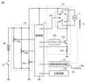
次に、切削工具5の回転駆動制御を行う根管治療器100の回路構成について、さらに詳しく説明する。図3は、実施の形態1に係る根管治療器100の回路構成を示す回路図である。図3に示す根管治療器100には、切削工具5の回転駆動制御に関わるマイクロモータ7、制御部11、比較回路110、根管長測定回路12、モータドライバ13、および設定部14の部分について図示してある。 Next, the circuit configuration of the root canal treatment device 100 that controls the rotational drive of the cutting tool 5 will be described in more detail. FIG. 3 is a circuit diagram showing the circuit configuration of the root canal treatment device 100 according to the first embodiment. In the root canal treatment device 100 shown in FIG. 3, the micromotor 7, the control unit 11, the comparison circuit 110, the root canal length measurement circuit 12, the motor driver 13, and the setting unit 14, which are involved in the rotational drive control of the cutting tool 5, are illustrated.

さらに、モータドライバ13は、トランジスタスイッチ13a、トランジスタドライバ回路13b、回転方向切替スイッチ13c、および負荷検出用抵抗13dを含んでいる。なお、回転方向切替スイッチ13cは、リレー素子として説明するが、FETなどの半導体のスイッチ素子でモータ駆動回路を構成してもよい。設定部14は、基準負荷設定用の可変抵抗14a、デューティ設定用の可変抵抗14b、および基準位置設定用の可変抵抗14cを含んでいる。なお、設定部14には、比較回路110において検出した負荷と基準負荷とを比較するタイミングを示す回転角度(または回転時間)を設定する構成なども含まれるが、当該構成については図3に図示していない。また、図3に示す根管治療器100には、主電源20およびメインスイッチ21に接続してある。切削工具5は、図示していないが適宜の歯車機構等を介してマイクロモータ7に保持してある。 The motor driver 13 further includes a transistor switch 13a, a transistor driver circuit 13b, a rotation direction switch 13c, and a load detection resistor 13d. The rotation direction switch 13c is described as a relay element, but the motor drive circuit may be configured with a semiconductor switch element such as an FET. The setting unit 14 includes a variable resistor 14a for setting a reference load, a variable resistor 14b for setting a duty, and a variable resistor 14c for setting a reference position. The setting unit 14 also includes a configuration for setting a rotation angle (or rotation time) indicating the timing for comparing the load detected by the comparison circuit 110 with the reference load, but this configuration is not shown in FIG. 3. The root canal treatment device 100 shown in FIG. 3 is connected to a main power source 20 and a main switch 21. The cutting tool 5 is held by the micromotor 7 via a suitable gear mechanism or the like, which is not shown.

トランジスタドライバ回路13bは、制御部11のポート11aから出力する制御信号で作動し、トランジスタスイッチ13aのオン・オフを制御してマイクロモータ7を駆動する。マイクロモータ7は、回転方向切替スイッチ13cの状態に応じて時計回り方向または反時計回り方向に回転する。制御部11のポート11aから出力する制御信号が、たとえば一定の周期で繰返されるパルス波形である場合、そのパルス波形の幅、すなわちデューティ比は、設定部14のデューティ設定用の可変抵抗14bによって調整される。マイクロモータ7は、このデューティ比に対応した回転数で切削工具5を駆動する。 The transistor driver circuit 13b operates with a control signal output from port 11a of the control unit 11, and controls the on/off of the transistor switch 13a to drive the micromotor 7. The micromotor 7 rotates clockwise or counterclockwise depending on the state of the rotation direction switch 13c. If the control signal output from port 11a of the control unit 11 is, for example, a pulse waveform that is repeated at a constant cycle, the width of the pulse waveform, i.e., the duty ratio, is adjusted by the duty setting variable resistor 14b of the setting unit 14. The micromotor 7 drives the cutting tool 5 at a rotation speed corresponding to this duty ratio.

回転方向切替スイッチ13cは、制御部11のポート11bから出力する制御信号で、切削工具5を時計回り方向に駆動するか、反時計回り方向に駆動するかを切替える。制御部11は、ポート11cに入力される負荷検出用抵抗13dの電流量(または電圧値)に基づき、切削工具5に加わる負荷を検出する。そのため、負荷検出用抵抗13dは、切削工具5に加わる負荷を検出する負荷検出部として機能している。なお、負荷検出部は、負荷検出用抵抗13dの電流量(または電圧値)に基づいて切削工具5に加わる負荷を検出する構成に限定されるものではなく、たとえば切削工具5の回転駆動部分にトルクセンサを設けて切削工具5に加わる負荷を検出する構成など別の構成であってもよい。検出される負荷は、たとえば切削工具5に加わるトルク値に制御部11で換算され、表示部16に表示される。また、比較回路110では、制御部11で換算されたトルク値と、基準負荷設定用の可変抵抗14aを用いて設定したトルク値とを比較している。もちろん、比較回路110は、トルク値に換算せずに負荷検出用抵抗13dの電流量(または電圧値)と可変抵抗14aの電流量(または電圧値)とを直接比較する構成でもよい。 The rotation direction switch 13c switches whether to drive the cutting tool 5 in a clockwise direction or a counterclockwise direction with a control signal output from the port 11b of the control unit 11. The control unit 11 detects the load applied to the cutting tool 5 based on the current amount (or voltage value) of the load detection resistor 13d input to the port 11c. Therefore, the load detection resistor 13d functions as a load detection unit that detects the load applied to the cutting tool 5. The load detection unit is not limited to a configuration that detects the load applied to the cutting tool 5 based on the current amount (or voltage value) of the load detection resistor 13d, and may have another configuration, such as a configuration in which a torque sensor is provided in the rotation drive part of the cutting tool 5 to detect the load applied to the cutting tool 5. The detected load is converted by the control unit 11 into a torque value applied to the cutting tool 5, for example, and displayed on the display unit 16. In addition, the comparison circuit 110 compares the torque value converted by the control unit 11 with the torque value set using the variable resistor 14a for setting the reference load. Of course, the comparison circuit 110 may be configured to directly compare the current (or voltage) of the load detection resistor 13d with the current (or voltage) of the variable resistor 14a without converting it to a torque value.

さらに、制御部11は、根管長測定回路12で測定した根管長をポート11dに入力する。そのため、根管長測定回路12は、切削工具5の先端の根管内での位置を検出する位置検出部として機能している。また、制御部11は、負荷検出部で検出した切削工具5に加わる負荷をポート11eから比較回路110へ出力し、比較回路110が基準負荷と比較した比較結果をポート11eから入力する。そのため、比較回路110は、負荷検出部で検出した負荷と基準負荷とを比較する負荷比較部として機能している。なお、制御部11は、上記アナログ回路で説明した構成を、ひとつのマイクロコンピュータにソフトウェアとしてまとめてもよい。 Furthermore, the control unit 11 inputs the root canal length measured by the root canal length measuring circuit 12 to port 11d. Therefore, the root canal length measuring circuit 12 functions as a position detection unit that detects the position of the tip of the cutting tool 5 within the root canal. The control unit 11 also outputs the load applied to the cutting tool 5 detected by the load detection unit from port 11e to the comparison circuit 110, and inputs the comparison result, which the comparison circuit 110 compares with a reference load, from port 11e. Therefore, the comparison circuit 110 functions as a load comparison unit that compares the load detected by the load detection unit with the reference load. Note that the control unit 11 may integrate the configuration described above in the analog circuit as software in a single microcomputer.

図4は、切削工具5の回転方向を示した模式図である。図4に示す切削工具5の回転方向では、ヘッド部2に取付ける切削工具5の側から切削工具5の先端方向を向いて切削工具5を右回りに回転させる時計回り方向5aの回転駆動と、左回りに回転させる反時計回り方向5bの回転駆動とが図示されている。切削工具5の刃5Aが時計回り方向の回転駆動をすることで根管を切削する場合、時計回り方向5aの回転駆動が正転駆動で、反時計回り方向5bの回転駆動が逆転駆動である。なお、予め定められた回転角度で時計回り方向5aに切削工具5を回転させる駆動と、予め定められた回転角度で反時計回り方向5bに切削工具5を回転させる駆動とを交互に行う駆動が、ツイスト駆動である。また、ツイスト駆動では、時計回り方向と反時計回り方向との交互回転を、等しい駆動量に行うものであってもよいし、異なる駆動量だけ行うものであってもよい。
[回転駆動の制御]
次に、実施の形態1に係る根管治療器100における回転駆動の制御について説明する。図5は、実施の形態1に係る根管治療器100における回転駆動の制御について説明するためのフローチャートである。図6は、実施の形態1に係る根管治療器における回転数および負荷の変化について説明するための図である。図6に示すグラフは、上段が回転数の変化を示すグラフで、下段が切削工具5に加わる負荷の変化を示すグラフである。回転数の変化を示すグラフは、縦軸が回転数で、横軸が時間である。切削工具5に加わる負荷の変化を示すグラフ、縦軸が切削工具5に加わる負荷で、横軸が時間である。実施の形態1に係る根管治療器100では、ツイスト駆動で切削工具5の回転駆動を行っているため、正転駆動と逆転駆動とを繰り返して行い切削工具5の回転の加速、減速を繰り返し行っている。そのため、単純に、回転加速度の大きさを大きくすると、切削効率は高くなるが、駆動部であるマイクロモータ7の振動も大きくなってしまう。
FIG. 4 is a schematic diagram showing the rotation direction of the cutting tool 5. In the rotation direction of the cutting tool 5 shown in FIG. 4, a clockwise rotation drive 5a for rotating the cutting tool 5 rightward from the side of the cutting tool 5 attached to the head portion 2 toward the tip of the cutting tool 5, and a counterclockwise rotation drive 5b for rotating the cutting tool 5 leftward are illustrated. When the blade 5A of the cutting tool 5 is rotated clockwise to cut a root canal, the clockwise rotation drive 5a is a forward rotation drive, and the counterclockwise rotation drive 5b is a reverse rotation drive. Note that a drive that alternates between a drive that rotates the cutting tool 5 in the clockwise direction 5a at a predetermined rotation angle and a drive that rotates the cutting tool 5 in the counterclockwise direction 5b at a predetermined rotation angle is a twist drive. In addition, in the twist drive, the clockwise and counterclockwise rotations may be alternately performed by the same drive amount or by different drive amounts.
[Rotation drive control]
Next, the control of the rotation drive in the root canal treatment device 100 according to the first embodiment will be described. FIG. 5 is a flow chart for explaining the control of the rotation drive in the root canal treatment device 100 according to the first embodiment. FIG. 6 is a diagram for explaining the change in the rotation speed and the load in the root canal treatment device according to the first embodiment. In the graph shown in FIG. 6, the upper part is a graph showing the change in the rotation speed, and the lower part is a graph showing the change in the load applied to the cutting tool 5. In the graph showing the change in the rotation speed, the vertical axis is the rotation speed and the horizontal axis is time. In the graph showing the change in the load applied to the cutting tool 5, the vertical axis is the load applied to the cutting tool 5 and the horizontal axis is time. In the root canal treatment device 100 according to the first embodiment, the cutting tool 5 is rotated by twist drive, so that the forward drive and the reverse drive are repeated to repeatedly accelerate and decelerate the rotation of the cutting tool 5. Therefore, simply increasing the magnitude of the rotation acceleration increases the cutting efficiency, but also increases the vibration of the micromotor 7, which is the drive unit.

そこで、実施の形態1に係る根管治療器100では、切削工具5に加わる負荷に着目して、切削工具5の回転加速度を制御する。具体的に、制御部11は、図5に示すように、切削工具5に加わる負荷が第1基準負荷以上か否かを判断する(ステップS101)。切削工具5に加わる負荷が第1基準負荷未満の場合(ステップS101でNO)、制御部11は、切削工具5の回転加速度の大きさを第1値として切削工具5を回転駆動する(ステップS102)。一方、切削工具5に加わる負荷が第1基準負荷以上の場合(ステップS101でYES)、制御部11は、切削工具5の回転加速度の大きさを第2値として切削工具5を回転駆動する(ステップS103)。なお、第2値は、第1値より大きい。 Therefore, in the root canal treatment device 100 according to the first embodiment, the rotational acceleration of the cutting tool 5 is controlled by focusing on the load applied to the cutting tool 5. Specifically, as shown in FIG. 5, the control unit 11 determines whether the load applied to the cutting tool 5 is equal to or greater than a first reference load (step S101). If the load applied to the cutting tool 5 is less than the first reference load (NO in step S101), the control unit 11 drives the cutting tool 5 to rotate with the magnitude of the rotational acceleration of the cutting tool 5 set to a first value (step S102). On the other hand, if the load applied to the cutting tool 5 is equal to or greater than the first reference load (YES in step S101), the control unit 11 drives the cutting tool 5 to rotate with the magnitude of the rotational acceleration of the cutting tool 5 set to a second value (step S103). The second value is greater than the first value.

つまり、切削工具5に加わる負荷が第1基準負荷より小さいとき、根管壁に切削工具5の刃が食い込んでいない、または食い込みが少ないので根管の切削への寄与が小さい。そのため、制御部11は、切削工具5の回転加速度を遅く(回転加速度の大きさを小さく)して、起動する期間および停止させる期間が長くなっても切削効率を低下させる虞は少ない。また、制御部11は、切削工具5の回転加速度を遅くすることで、マイクロモータ7の振動を小さく抑制することができる。 In other words, when the load applied to the cutting tool 5 is smaller than the first reference load, the blade of the cutting tool 5 does not or only little penetrates into the root canal wall, so its contribution to cutting the root canal is small. Therefore, the control unit 11 slows down the rotational acceleration of the cutting tool 5 (reducing the magnitude of the rotational acceleration), so that there is little risk of reducing cutting efficiency even if the start-up period and stop period are extended. In addition, by slowing down the rotational acceleration of the cutting tool 5, the control unit 11 can suppress the vibration of the micromotor 7 to a small extent.

一方、切削工具5に加わる負荷が第1基準負荷以上のとき、根管壁に切削工具5の刃が食い込んでいるので根管の切削への寄与が大きい。そのため、制御部11は、切削工具5の回転加速度を速く(回転加速度の大きさを大きく)して、起動する期間および停止させる期間を短くすることで高い切削効率を維持できる。ただ、制御部11は、切削工具5の回転加速度を速くするので、マイクロモータ7の振動は大きくなる。 On the other hand, when the load applied to the cutting tool 5 is equal to or greater than the first reference load, the blade of the cutting tool 5 bites into the root canal wall, so that it contributes greatly to cutting the root canal. Therefore, the control unit 11 can maintain high cutting efficiency by increasing the rotational acceleration of the cutting tool 5 (increasing the magnitude of the rotational acceleration) and shortening the start and stop periods. However, because the control unit 11 increases the rotational acceleration of the cutting tool 5, the vibration of the micromotor 7 increases.

図6に示すように、切削工具5に加わる負荷が第1基準負荷未満において、切削工具5の回転駆動が切り替わる際に、正転から停止までの減速、および停止から逆転までの加速の期間A、逆転から停止までの減速、および停止から正転までの加速の期間Bの回転加速度の大きさを第1値(<第2値)と小さくする。 As shown in FIG. 6, when the load applied to the cutting tool 5 is less than a first reference load, the magnitude of the rotational acceleration during period A of deceleration from forward rotation to a stop and acceleration from the stop to reverse rotation, and period B of deceleration from reverse rotation to a stop and acceleration from the stop to forward rotation, is reduced to a first value (< second value) when the rotational drive of the cutting tool 5 is switched.

一方、切削工具5に加わる負荷が第1基準負荷以上において、切削工具5の回転駆動が切り替わる際に、正転から停止までの減速、および停止から逆転までの加速の期間C、逆転から停止までの減速、および停止から正転までの加速の期間Dの回転加速度の大きさを第2値(>第1値)と大きくする。 On the other hand, when the load applied to the cutting tool 5 is equal to or greater than the first reference load, the magnitude of the rotational acceleration during period C of deceleration from forward rotation to a stop and acceleration from the stop to reverse rotation, and during period D of deceleration from reverse rotation to a stop and acceleration from the stop to forward rotation, is increased to a second value (> first value) when the rotational drive of the cutting tool 5 is switched.

第1値は、第2値の1/3~2/3の大きさであることが望ましい。マイクロモータ7の種類やハンドピース1の構造により第1値および第2値は変化するが、マイクロモータ7の振動を抑えつつ、切削効率の良い切削工具の回転駆動を行うことができる最適な第1値および第2値を複数回実験の実験結果から決定してもよい。 It is desirable that the first value be 1/3 to 2/3 of the second value. The first and second values vary depending on the type of micromotor 7 and the structure of the handpiece 1, but the optimal first and second values that can suppress vibration of the micromotor 7 while rotating the cutting tool with good cutting efficiency may be determined from the experimental results of multiple experiments.

図5に示すフローチャートでは、制御部11で停止操作を受け付けたか否かを判断する(ステップS104)。駆動開始・停止ボタン15aが押下されて、停止操作を受け付けた場合(ステップS104でYES)、制御部11は、切削工具5の回転駆動を停止する。一方、停止操作を受け付けていない場合(ステップS104でNO)、制御部11は、処理をステップS101に戻す。つまり、制御部11は、切削工具5に加わる負荷が第1基準負荷以上か否かで、切削工具5の回転加速度を切り替えてツイスト駆動を行う。 In the flowchart shown in FIG. 5, the control unit 11 determines whether or not a stop operation has been received (step S104). When the drive start/stop button 15a is pressed and a stop operation is received (YES in step S104), the control unit 11 stops the rotational drive of the cutting tool 5. On the other hand, when a stop operation has not been received (NO in step S104), the control unit 11 returns the process to step S101. In other words, the control unit 11 switches the rotational acceleration of the cutting tool 5 and performs twist drive depending on whether the load applied to the cutting tool 5 is equal to or greater than the first reference load.

図6に示した例では、制御部11は、切削工具5に加わる負荷が第1基準負荷以上か否かで、切削工具5の回転加速度を第1値か第2値かに切り替えていたが、基準負荷を複数設け、切削工具5の回転加速度を複数の値に切り替えてもよい。これにより、制御部11は、マイクロモータ7の振動をより抑えつつ、より切削効率の良い切削工具の回転駆動を行うことができる。 In the example shown in FIG. 6, the control unit 11 switches the rotational acceleration of the cutting tool 5 between a first value and a second value depending on whether the load applied to the cutting tool 5 is equal to or greater than a first reference load. However, multiple reference loads may be provided and the rotational acceleration of the cutting tool 5 may be switched between multiple values. This allows the control unit 11 to perform rotational driving of the cutting tool with better cutting efficiency while further suppressing vibration of the micromotor 7.

実際の切削工具5の回転駆動では、負荷検出部において切削工具5に加わる負荷を検出してから切削工具5の回転加速度の切り替え制御までの間に数msec程度のタイムラグが生じる。しかし、図6に示すグラフでは、当該タイムラグは小さいとして当該タイムラグを無視して図示していない。 In the actual rotational drive of the cutting tool 5, a time lag of several msec occurs between the load detection unit detecting the load applied to the cutting tool 5 and the switching control of the rotational acceleration of the cutting tool 5. However, in the graph shown in Figure 6, this time lag is ignored as it is considered to be small and is not shown.

以上のように、実施の形態1に係る根管治療器100は、歯牙の根管を治療する歯科用治療装置である。根管治療器100は、ハンドピース1のヘッド部2に保持した、根管を切削するための切削工具5を回転駆動するマイクロモータ7と、切削工具5を回転駆動するマイクロモータ7を制御する制御部11と、切削工具5に加わる負荷を検出する負荷検出部(負荷検出用抵抗13d)と、を備える。制御部11は、負荷検出部で検出する切削工具5に加わる負荷に応じて、切削工具5の回転加速度を変更するようにマイクロモータ7を制御する。 As described above, the root canal treatment device 100 according to the first embodiment is a dental treatment device for treating the root canal of a tooth. The root canal treatment device 100 includes a micromotor 7 that rotates and drives the cutting tool 5 for cutting the root canal, which is held in the head portion 2 of the handpiece 1, a control portion 11 that controls the micromotor 7 that rotates and drives the cutting tool 5, and a load detection portion (load detection resistor 13d) that detects the load applied to the cutting tool 5. The control portion 11 controls the micromotor 7 to change the rotational acceleration of the cutting tool 5 according to the load applied to the cutting tool 5 detected by the load detection portion.

具体的に、制御部11は、負荷検出部で検出する切削工具5に加わる負荷が第1基準負荷未満である場合、起動する期間および停止させる期間の切削工具5の回転加速度の大きさを第1値とし、負荷検出部で検出する切削工具5に加わる負荷が第1基準負荷以上である場合、起動する期間および停止させる期間の切削工具5の回転加速度の大きさを第1値より大きい第2値としてマイクロモータ7を制御する。これにより、実施の形態1に係る根管治療器100は、切削工具5に加わる負荷に応じて、切削工具5の回転加速度を変更するようにマイクロモータ7を制御するので、マイクロモータ7の振動を抑えつつ、切削効率の良い切削工具5の回転駆動を行うことができる。
(実施の形態2)
実施の形態1に係る根管治療器100では、切削工具5をツイスト駆動する場合に、切削工具5に加わる負荷に応じて、切削工具5の回転加速度を変更するようにマイクロモータ7を制御する構成について説明した。実施の形態2に係る根管治療器では、所定の負荷が切削工具に加わった場合に切削工具を逆転させる駆動において、切削工具に加わる負荷に応じて、切削工具の回転加速度を変更するようにマイクロモータを制御する構成について説明する。なお、実施の形態2に係る根管治療器100でも、図1~図3に示した実施の形態1に係る根管治療器100と同じ構成を用いるため、同じ構成には同じ符号を用いて詳しい説明を繰返さない。
Specifically, the control unit 11 controls the micromotor 7 to set the magnitude of the rotational acceleration of the cutting tool 5 during the start and stop periods to a first value when the load on the cutting tool 5 detected by the load detection unit is less than a first reference load, and to set the magnitude of the rotational acceleration of the cutting tool 5 during the start and stop periods to a second value greater than the first value when the load on the cutting tool 5 detected by the load detection unit is equal to or greater than the first reference load. As a result, the root canal treatment device 100 according to the first embodiment controls the micromotor 7 to change the rotational acceleration of the cutting tool 5 in accordance with the load on the cutting tool 5, so that the cutting tool 5 can be rotated and driven with good cutting efficiency while suppressing vibration of the micromotor 7.
(Embodiment 2)
In the root canal treating instrument 100 according to the first embodiment, a configuration has been described in which the micromotor 7 is controlled to change the rotational acceleration of the cutting tool 5 in response to the load applied to the cutting tool 5 when the cutting tool 5 is twist-driven. In the root canal treating instrument according to the second embodiment, a configuration has been described in which the micromotor is controlled to change the rotational acceleration of the cutting tool in response to the load applied to the cutting tool when the cutting tool is driven to rotate in the reverse direction when a predetermined load is applied to the cutting tool. Note that the root canal treating instrument 100 according to the second embodiment uses the same components as the root canal treating instrument 100 according to the first embodiment shown in Figures 1 to 3, and therefore the same components are designated by the same reference numerals and detailed description thereof will not be repeated.

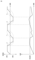
図7は、実施の形態2に係る根管治療器100における回転駆動の制御について説明するためのフローチャートである。図8は、実施の形態2に係る根管治療器100における回転数および負荷の変化について説明するための図である。図7に示すグラフは、上段が回転数の変化を示すグラフで、下段が切削工具5に加わる負荷の変化を示すグラフである。回転数の変化を示すグラフは、縦軸が回転数で、横軸が時間である。切削工具5に加わる負荷の変化を示すグラフ、縦軸が切削工具5に加わる負荷で、横軸が時間である。実施の形態2に係る根管治療器100では、正転駆動で切削工具5の回転駆動を行っているが、切削工具5に加わる負荷が第2基準負荷以上になると、切削工具5の破損を防止するため逆転駆動に切り替える制御を行っている。第2基準負荷は、切削工具5の材質や形状などにより予め設定してある。 Figure 7 is a flow chart for explaining the control of the rotation drive in the root canal treatment device 100 according to the second embodiment. Figure 8 is a diagram for explaining the change in the rotation speed and the load in the root canal treatment device 100 according to the second embodiment. In the graph shown in Figure 7, the upper part shows the change in the rotation speed, and the lower part shows the change in the load applied to the cutting tool 5. In the graph showing the change in the rotation speed, the vertical axis is the rotation speed and the horizontal axis is time. In the graph showing the change in the load applied to the cutting tool 5, the vertical axis is the load applied to the cutting tool 5 and the horizontal axis is time. In the root canal treatment device 100 according to the second embodiment, the cutting tool 5 is rotated by forward drive, but when the load applied to the cutting tool 5 becomes equal to or greater than the second reference load, the cutting tool 5 is controlled to be switched to reverse drive to prevent damage to the cutting tool 5. The second reference load is preset according to the material and shape of the cutting tool 5.

実施の形態2に係る根管治療器100においても、切削工具5に加わる負荷に着目して、切削工具5の回転加速度を制御する。具体的に、制御部11は、図7に示すように、切削工具5に加わる負荷が第2基準負荷以上か否かを判断する(ステップS201)。切削工具5に加わる負荷が第2基準負荷未満の場合(ステップS201でNO)、制御部11は、回転駆動を正転駆動に切り替える(ステップS202)。なお、ステップS202において、制御部11が、正転駆動で切削工具5の回転駆動を行っている場合、正転駆動を継続することになる。次に、制御部11は、切削工具5の回転加速度の大きさを第3値として切削工具5を回転駆動する(ステップS203)。 In the root canal treatment device 100 according to the second embodiment, the rotational acceleration of the cutting tool 5 is controlled by focusing on the load applied to the cutting tool 5. Specifically, as shown in FIG. 7, the control unit 11 determines whether the load applied to the cutting tool 5 is equal to or greater than the second reference load (step S201). If the load applied to the cutting tool 5 is less than the second reference load (NO in step S201), the control unit 11 switches the rotational drive to forward drive (step S202). Note that in step S202, if the control unit 11 is rotating the cutting tool 5 in forward drive, the forward drive will be continued. Next, the control unit 11 rotates the cutting tool 5 with the magnitude of the rotational acceleration of the cutting tool 5 as a third value (step S203).

一方、切削工具5に加わる負荷が第2基準負荷以上の場合(ステップS201でYES)、制御部11は、回転駆動を逆転駆動に切り替える(ステップS204)。なお、ステップS202において、制御部11が、逆転駆動で切削工具5の回転駆動を行っている場合、逆転駆動を継続することになる。次に、制御部11は、切削工具5の回転加速度の大きさを第4値として切削工具5を回転駆動する(ステップS205)。なお、第4値は、第3値より大きい。 On the other hand, if the load applied to the cutting tool 5 is equal to or greater than the second reference load (YES in step S201), the control unit 11 switches the rotation drive to reverse drive (step S204). Note that in step S202, if the control unit 11 is rotating the cutting tool 5 in reverse drive, the reverse drive will be continued. Next, the control unit 11 rotates the cutting tool 5 with the magnitude of the rotational acceleration of the cutting tool 5 set as a fourth value (step S205). Note that the fourth value is greater than the third value.

つまり、切削工具5に加わる負荷が第2基準負荷より小さいとき、制御部11は、マイクロモータ7の振動を小さく抑えつつ、根管を切削拡大することができる程度の回転加速度で切削工具5を回転駆動する。一方、切削工具5に加わる負荷が第2基準負荷以上のとき、根管壁に切削工具5の刃が食い込んで動かなくなっているので、制御部11は、切削工具5の回転加速度を速くして、切削工具の刃の根管壁への食い込みを素早く解除する。 In other words, when the load applied to the cutting tool 5 is smaller than the second reference load, the control unit 11 rotates and drives the cutting tool 5 at a rotational acceleration that can cut and enlarge the root canal while keeping the vibration of the micromotor 7 small. On the other hand, when the load applied to the cutting tool 5 is equal to or greater than the second reference load, the blade of the cutting tool 5 is stuck in the root canal wall and cannot move, so the control unit 11 increases the rotational acceleration of the cutting tool 5 to quickly release the blade of the cutting tool from the root canal wall.

実施の形態2に係る根管治療器100は、切削工具の刃の根管壁への食い込みを素早く解除して、根管を切削拡大する切削工具5の回転駆動に戻すことができれば、高い切削効率を維持することができる。ただ、制御部11は、切削工具の刃の根管壁への食い込みを解除する期間、切削工具5の回転加速度を速くするので、マイクロモータ7の振動は大きくなる。 The root canal treatment device 100 according to the second embodiment can maintain high cutting efficiency if it can quickly release the cutting tool blade from biting into the root canal wall and return to the rotational drive of the cutting tool 5, which cuts and enlarges the root canal. However, the control unit 11 increases the rotational acceleration of the cutting tool 5 during the period when the cutting tool blade is releasing the cutting tool blade from biting into the root canal wall, so the vibration of the micromotor 7 increases.

図7に示すように、切削工具5に加わる負荷が第2基準負荷以上になると、切削工具5の回転駆動を切り替え、切削工具5に加わる負荷を緩和する駆動を行っている。そのため、切削工具5に加わる負荷が第2基準負荷以上になり、正転から停止までの減速、および停止から逆転までの加速の期間E,Gの回転加速度の大きさを第4値(>第3値)と大きくする。 As shown in FIG. 7, when the load applied to the cutting tool 5 becomes equal to or greater than the second reference load, the rotational drive of the cutting tool 5 is switched, and driving is performed to reduce the load applied to the cutting tool 5. Therefore, when the load applied to the cutting tool 5 becomes equal to or greater than the second reference load, the magnitude of the rotational acceleration during periods E and G of deceleration from forward rotation to a stop and acceleration from a stop to reverse rotation is increased to a fourth value (> third value).

切削工具5に加わる負荷が第2基準負荷未満になるまで、制御部11は、切削工具5の回転駆動を逆転駆動のまま維持することになる。切削工具5に加わる負荷が第2基準負荷未満になり、切削工具5の回転駆動を逆転駆動から正転駆動に切り替える場合、逆転から停止までの減速、および停止から正転までの加速の期間F,Hの回転加速度の大きさを第3値(<第4値)と小さくする。 The control unit 11 will maintain the rotational drive of the cutting tool 5 in reverse drive until the load applied to the cutting tool 5 falls below the second reference load. When the load applied to the cutting tool 5 falls below the second reference load and the rotational drive of the cutting tool 5 is switched from reverse drive to forward drive, the magnitude of the rotational acceleration during periods F and H of deceleration from reverse rotation to stop and acceleration from stop to forward rotation is reduced to a third value (<fourth value).

図7に示すフローチャートでは、制御部11で停止操作を受け付けたか否かを判断する(ステップS206)。駆動開始・停止ボタン15aが押下されて、停止操作を受け付けた場合(ステップS206でYES)、制御部11は、切削工具5の回転駆動を停止する。一方、停止操作を受け付けていない場合(ステップS206でNO)、制御部11は、処理をステップS201に戻す。つまり、制御部11は、切削工具5に加わる負荷が第2基準負荷以上か否かで、切削工具5の回転駆動を逆転駆動に切り替える駆動を行う。 In the flowchart shown in FIG. 7, the control unit 11 determines whether or not a stop operation has been received (step S206). When the drive start/stop button 15a is pressed and a stop operation is received (YES in step S206), the control unit 11 stops the rotational drive of the cutting tool 5. On the other hand, when a stop operation has not been received (NO in step S206), the control unit 11 returns the process to step S201. In other words, the control unit 11 performs a drive to switch the rotational drive of the cutting tool 5 to reverse drive depending on whether or not the load applied to the cutting tool 5 is equal to or greater than the second reference load.

実施の形態2に係る切削工具5の回転駆動は、切削工具5に加わる負荷が第2基準負荷未満において正転駆動であると説明したがツイスト駆動であってもよい。切削工具5に加わる負荷が第2基準負荷未満において切削工具5をツイスト駆動させる場合、実施の形態1で説明した駆動を実施の形態2で説明した駆動に組み合わせてもよい。 The rotational drive of the cutting tool 5 according to the second embodiment has been described as a forward drive when the load applied to the cutting tool 5 is less than the second reference load, but it may also be a twist drive. When the cutting tool 5 is twist driven when the load applied to the cutting tool 5 is less than the second reference load, the drive described in the first embodiment may be combined with the drive described in the second embodiment.

以上のように、実施の形態2に係る根管治療器100は、制御部11が、負荷検出部で検出する切削工具5に加わる負荷が第2基準負荷以上である場合、切削工具5が切削対象物を切削する正転駆動とは逆方向の逆転駆動に切り替え、負荷検出部で検出する切削工具5に加わる負荷が第2基準負荷未満である場合、起動する期間および停止させる期間の切削工具5の回転加速度の大きさを第3値とし、負荷検出部で検出する切削工具5に加わる負荷が第2基準負荷以上である場合、起動する期間および停止させる期間の切削工具5の回転加速度の大きさを第3値より大きい第4値としてマイクロモータ7を制御する。
(実施の形態3)
実施の形態1に係る根管治療器100では、切削工具5に加わる負荷に応じて、切削工具5の回転加速度を変更するようにマイクロモータ7を制御する構成について説明した。実施の形態3に係る根管治療器では、切削工具5に加わる負荷以外の値に応じて切削工具5の回転加速度を変更するようにマイクロモータ7を制御する構成について説明する。なお、実施の形態3に係る根管治療器100でも、図1~図3に示した実施の形態1に係る根管治療器100と同じ構成を用いるため、同じ構成には同じ符号を用いて詳しい説明を繰返さない。
As described above, in the root canal treatment device 100 according to the second embodiment, when the load applied to the cutting tool 5 detected by the load detection unit is equal to or greater than the second standard load, the control unit 11 switches to reverse drive in the opposite direction to the forward drive in which the cutting tool 5 cuts the object to be cut, and when the load applied to the cutting tool 5 detected by the load detection unit is less than the second standard load, the control unit 11 sets the magnitude of the rotational acceleration of the cutting tool 5 during the start-up period and the stop-up period to a third value, and when the load applied to the cutting tool 5 detected by the load detection unit is equal to or greater than the second standard load, the control unit 11 controls the micromotor 7 to set the magnitude of the rotational acceleration of the cutting tool 5 during the start-up period and the stop-up period to a fourth value greater than the third value.
(Embodiment 3)
In the root canal treating device 100 according to the first embodiment, a configuration has been described in which the micromotor 7 is controlled so as to change the rotational acceleration of the cutting tool 5 in response to the load applied to the cutting tool 5. In the root canal treating device according to the third embodiment, a configuration has been described in which the micromotor 7 is controlled so as to change the rotational acceleration of the cutting tool 5 in response to a value other than the load applied to the cutting tool 5. Note that the root canal treating device 100 according to the third embodiment also uses the same components as the root canal treating device 100 according to the first embodiment shown in Figures 1 to 3, and therefore the same components will be designated by the same reference numerals and detailed description will not be repeated.

図9は、実施の形態3に係る根管治療器100における回転駆動の制御について説明するためのフローチャートである。まず、実施の形態3に係る根管治療器100では、切削工具5の回転速度に応じて、切削工具5の回転加速度を変更するようにマイクロモータ7を制御する構成について説明する。切削工具5の回転速度は、選択ボタン15bを操作することで設定することができるが、設定した切削工具5の回転速度が速いと、起動する期間および停止させる期間が長くなり切削効率が低下する虞がある。 Figure 9 is a flow chart for explaining the control of the rotation drive in the root canal treatment device 100 according to the third embodiment. First, a configuration for controlling the micromotor 7 so as to change the rotation acceleration of the cutting tool 5 according to the rotation speed of the cutting tool 5 in the root canal treatment device 100 according to the third embodiment will be explained. The rotation speed of the cutting tool 5 can be set by operating the selection button 15b, but if the set rotation speed of the cutting tool 5 is fast, the start period and stop period will be long, which may reduce the cutting efficiency.

そこで、実施の形態3に係る根管治療器100では、切削工具5の回転速度に応じて、切削工具5の回転加速度を制御する。具体的に、制御部11は、図9に示すように、切削工具5の回転速度を設定する(ステップS301)。制御部11は、設定した切削工具5の回転速度が基準回転速度以上か否かを判断する(ステップS302)。切削工具5の回転速度が基準速度未満の場合(ステップS302でNO)、制御部11は、切削工具5の回転加速度の大きさを第5値として切削工具5を回転駆動する(ステップS303)。一方、設定した切削工具5の回転速度が基準速度以上の場合(ステップS302でYES)、制御部11は、切削工具5の回転加速度の大きさを第6値として切削工具5を回転駆動する(ステップS304)。なお、第6値は、第5値より大きい。 Therefore, in the root canal treatment device 100 according to the third embodiment, the rotational acceleration of the cutting tool 5 is controlled according to the rotational speed of the cutting tool 5. Specifically, the control unit 11 sets the rotational speed of the cutting tool 5 as shown in FIG. 9 (step S301). The control unit 11 judges whether the set rotational speed of the cutting tool 5 is equal to or higher than the reference rotational speed (step S302). If the rotational speed of the cutting tool 5 is lower than the reference speed (NO in step S302), the control unit 11 drives the cutting tool 5 to rotate with the magnitude of the rotational acceleration of the cutting tool 5 set as a fifth value (step S303). On the other hand, if the set rotational speed of the cutting tool 5 is equal to or higher than the reference speed (YES in step S302), the control unit 11 drives the cutting tool 5 to rotate with the magnitude of the rotational acceleration of the cutting tool 5 set as a sixth value (step S304). The sixth value is greater than the fifth value.

つまり、設定した切削工具5の回転速度が基準速度より小さいとき、設定した切削工具5の回転速度に達するまでの期間(起動する期間)および設定した切削工具5の回転速度から停止するまでの期間(停止させる期間)が短い。しかし、設定した切削工具5の回転速度が基準速度以上のとき、設定した切削工具5の回転速度に達するまでの期間(起動する期間)および設定した切削工具5の回転速度から停止するまでの期間(停止させる期間)が長くなるので、切削工具5の回転加速度の大きさを大きくしなければ切削効率を低下させる虞が生じる。なお、設定した切削工具5の回転速度が基準速度より小さいときは切削工具5の回転加速度の大きさを小さくすることで、マイクロモータ7の振動を小さく抑制することができる。 In other words, when the set rotational speed of the cutting tool 5 is smaller than the reference speed, the period until the set rotational speed of the cutting tool 5 is reached (starting period) and the period until the cutting tool 5 stops from the set rotational speed (stopping period) are short. However, when the set rotational speed of the cutting tool 5 is equal to or greater than the reference speed, the period until the set rotational speed of the cutting tool 5 is reached (starting period) and the period until the cutting tool 5 stops from the set rotational speed (stopping period) are long, so there is a risk of reducing the cutting efficiency unless the magnitude of the rotational acceleration of the cutting tool 5 is increased. Note that when the set rotational speed of the cutting tool 5 is smaller than the reference speed, the vibration of the micromotor 7 can be suppressed to a small value by reducing the magnitude of the rotational acceleration of the cutting tool 5.

図9に示すフローチャートでは、制御部11で停止操作を受け付けたか否かを判断する(ステップS305)。駆動開始・停止ボタン15aが押下されて、停止操作を受け付けた場合(ステップS305でYES)、制御部11は、切削工具5の回転駆動を停止する。一方、停止操作を受け付けていない場合(ステップS305でNO)、制御部11は、切削工具5の回転速度を変更する操作を受け付けたか否かを判断する(ステップS306)。回転速度を変更する操作を受け付けた場合(ステップS306でYES)、制御部11は、処理をステップS301に戻す。つまり、制御部11は、新たに切削工具5の回転速度を設定する。回転速度を変更する操作を受け付けた場合(ステップS306でYES)、制御部11は、処理をステップS305に戻す。つまり、制御部11は、同じ回転速度で切削工具5の回転駆動を継続する。 In the flowchart shown in FIG. 9, the control unit 11 determines whether or not a stop operation has been received (step S305). When the drive start/stop button 15a is pressed and a stop operation has been received (YES in step S305), the control unit 11 stops the rotational drive of the cutting tool 5. On the other hand, when a stop operation has not been received (NO in step S305), the control unit 11 determines whether or not an operation to change the rotational speed of the cutting tool 5 has been received (step S306). When an operation to change the rotational speed has been received (YES in step S306), the control unit 11 returns the process to step S301. That is, the control unit 11 sets a new rotational speed of the cutting tool 5. When an operation to change the rotational speed has been received (YES in step S306), the control unit 11 returns the process to step S305. That is, the control unit 11 continues the rotational drive of the cutting tool 5 at the same rotational speed.

図9に示した例では、制御部11は、設定した切削工具5の回転速度が基準速度以上か否かで、切削工具5の回転加速度を第5値か第6値かで切り替えていたが、基準速度を複数設け、切削工具5の回転加速度を複数の値に切り替えてもよい。また、図9に示した例では、制御部11は、設定した切削工具5の回転速度に応じて、切削工具5の回転加速度を変更するようにマイクロモータ7を制御するが、他の実施の形態で説明した制御と組み合わせ制御してもよい。 In the example shown in FIG. 9, the control unit 11 switches the rotational acceleration of the cutting tool 5 between a fifth value and a sixth value depending on whether the set rotational speed of the cutting tool 5 is equal to or greater than a reference speed, but multiple reference speeds may be provided and the rotational acceleration of the cutting tool 5 may be switched between multiple values. Also, in the example shown in FIG. 9, the control unit 11 controls the micromotor 7 to change the rotational acceleration of the cutting tool 5 depending on the set rotational speed of the cutting tool 5, but this control may be combined with the control described in the other embodiments.

さらに、図10は、実施の形態3に係る根管治療器における回転駆動の別の制御について説明するためのフローチャートである。図10に示すフローチャートでは、切削工具5の先端の位置に応じて、切削工具5の回転加速度を変更するようにマイクロモータ7を制御する構成について説明する。根尖位置に近づくほど根管は細くなるので切削工具に加わる負荷が大きくなるため、切削効率を低下させないために切削工具5の回転加速度の大きさを大きくすることか好ましい。 Furthermore, FIG. 10 is a flowchart for explaining another control of the rotational drive in the root canal treatment device according to embodiment 3. The flowchart shown in FIG. 10 explains a configuration for controlling the micromotor 7 so as to change the rotational acceleration of the cutting tool 5 according to the position of the tip of the cutting tool 5. Since the root canal becomes thinner as it approaches the apex position and therefore the load applied to the cutting tool increases, it is preferable to increase the magnitude of the rotational acceleration of the cutting tool 5 in order not to reduce the cutting efficiency.

そこで、根管治療器100では、切削工具5の先端の位置に応じて、切削工具5の回転加速度を制御する。具体的に、制御部11は、図10に示すように、制御部11は、根管長測定回路12から得た切削工具5の先端の位置が基準位置より根尖に近いか否かを判断する(ステップS401)。切削工具5の先端の位置が基準位置より根尖から遠い場合(ステップS401でNO)、制御部11は、切削工具5の回転加速度の大きさを第7値として切削工具5を回転駆動する(ステップS402)。一方、切削工具5の先端の位置が基準位置より根尖に近い場合(ステップS401でYES)、制御部11は、切削工具5の回転加速度の大きさを第8値として切削工具5を回転駆動する(ステップS403)。なお、第8値は、第7値より大きい。 Therefore, in the root canal treatment device 100, the rotational acceleration of the cutting tool 5 is controlled according to the position of the tip of the cutting tool 5. Specifically, as shown in FIG. 10, the control unit 11 determines whether the position of the tip of the cutting tool 5 obtained from the root canal length measurement circuit 12 is closer to the root apex than the reference position (step S401). If the position of the tip of the cutting tool 5 is farther from the root apex than the reference position (NO in step S401), the control unit 11 drives the cutting tool 5 to rotate with the magnitude of the rotational acceleration of the cutting tool 5 set to a seventh value (step S402). On the other hand, if the position of the tip of the cutting tool 5 is closer to the root apex than the reference position (YES in step S401), the control unit 11 drives the cutting tool 5 to rotate with the magnitude of the rotational acceleration of the cutting tool 5 set to an eighth value (step S403). Note that the eighth value is greater than the seventh value.

つまり、切削工具5の先端の位置が基準位置より根尖から遠い場合、切削工具5に加わる負荷は小さいが、切削工具5の先端の位置が基準位置より根尖に近い場合、切削工具5に加わる負荷は大きくなる。そのため、制御部11は、切削工具5に加わる負荷が小さくなる位置では、切削工具5の回転加速度を遅くすることで、マイクロモータ7の振動を小さく抑制することができる。一方、制御部11は、切削工具5に加わる負荷が大きくなる位置では、切削工具5の回転加速度を速くするので、高い切削効率を維持できる。 In other words, when the position of the tip of the cutting tool 5 is farther from the root apex than the reference position, the load applied to the cutting tool 5 is small, but when the position of the tip of the cutting tool 5 is closer to the root apex than the reference position, the load applied to the cutting tool 5 is large. Therefore, the control unit 11 can reduce the vibration of the micromotor 7 by slowing down the rotational acceleration of the cutting tool 5 at a position where the load applied to the cutting tool 5 is small. On the other hand, the control unit 11 can increase the rotational acceleration of the cutting tool 5 at a position where the load applied to the cutting tool 5 is large, thereby maintaining high cutting efficiency.

図10に示した例では、制御部11は、切削工具5の先端の位置が基準位置より根尖に近いか否かで、切削工具5の回転加速度を第7値か第8値かで切り替えていたが、基準位置を複数設け、切削工具5の回転加速度を複数の値に切り替えてもよい。また、図10に示した例では、制御部11は、切削工具5の先端の位置に応じて、切削工具5の回転加速度を変更するようにマイクロモータ7を制御するが、他の実施の形態で説明した制御を組み合わせて制御してもよい。また、切削工具5の先端の位置は、切削工具5に加わる負荷に対応するため、制御部11は、切削工具5に加わる負荷を測定することに代えて、切削工具5の先端の位置に応じて、切削工具5の回転加速度を変更するようにマイクロモータ7を制御してもよい。 In the example shown in FIG. 10, the control unit 11 switches the rotational acceleration of the cutting tool 5 between the seventh value and the eighth value depending on whether the position of the tip of the cutting tool 5 is closer to the apex than the reference position, but multiple reference positions may be provided and the rotational acceleration of the cutting tool 5 may be switched between multiple values. In the example shown in FIG. 10, the control unit 11 controls the micromotor 7 to change the rotational acceleration of the cutting tool 5 depending on the position of the tip of the cutting tool 5, but the control may be performed by combining the controls described in the other embodiments. In addition, since the position of the tip of the cutting tool 5 corresponds to the load applied to the cutting tool 5, the control unit 11 may control the micromotor 7 to change the rotational acceleration of the cutting tool 5 depending on the position of the tip of the cutting tool 5 instead of measuring the load applied to the cutting tool 5.

図10に示した例では、制御部11は、切削工具5の先端の位置が基準位置より根尖に近い場合、高い切削効率を維持するため切削工具5の回転加速度を速くして切削工具5に加わる負荷を大きすると説明した。しかし、根尖付近で過剰な切削を防ぐ必要がある場合、根尖付近に閾値をさらに設けて当該閾値より根尖に切削工具5の先端の位置が近づいたとき、切削工具5の回転加速度を遅くして回転数を低下させて切削工具5に加わる負荷を小さくしてもよい。もちろん、他の実施の形態に係る根管治療器においても、根管長測定回路12を有し切削工具5の先端の位置を得ることができるのであれば、根尖付近で過剰な切削を防ぐために切削工具5の回転数を低下させてもよい。 In the example shown in FIG. 10, the control unit 11 has been explained as increasing the rotational acceleration of the cutting tool 5 to increase the load on the cutting tool 5 in order to maintain high cutting efficiency when the position of the tip of the cutting tool 5 is closer to the root apex than the reference position. However, if it is necessary to prevent excessive cutting near the root apex, a threshold value may be further set near the root apex, and when the position of the tip of the cutting tool 5 approaches the root apex closer than the threshold value, the rotational acceleration of the cutting tool 5 may be slowed down to reduce the rotation speed and reduce the load on the cutting tool 5. Of course, in root canal treatment devices according to other embodiments, if they have a root canal length measurement circuit 12 and can obtain the position of the tip of the cutting tool 5, the rotation speed of the cutting tool 5 may be reduced to prevent excessive cutting near the root apex.

(変形例)
(1)実施の形態1に係る根管治療器100では、切削工具5に加わる負荷に応じて、切削工具5の回転加速度を変更する構成を説明した。しかし、切削工具5に加わる負荷に関わらず、同じ回転加速度で切削工具を回転駆動する駆動モードと、切削工具5に加わる負荷に応じて、切削工具5の回転加速度を変更する駆動モードを切り替えることができるようにしてもよい。
(Modification)
(1) In the root canal treatment device 100 according to the first embodiment, the rotational acceleration of the cutting tool 5 is changed in response to the load applied to the cutting tool 5. However, it is also possible to switch between a drive mode in which the cutting tool is rotationally driven at the same rotational acceleration regardless of the load applied to the cutting tool 5, and a drive mode in which the rotational acceleration of the cutting tool 5 is changed in response to the load applied to the cutting tool 5.

図11は、駆動モードの切り替えについて説明するためのフローチャートである。まず、操作者(術者)は選択ボタン15bを操作することで駆動モードの選択することができ、制御部11は、選択された駆動モードが第1モードか否かを判断する(ステップS501)。ここで、第1モードは、切削工具5に加わる負荷に関わらず、同じ回転加速度で切削工具を回転駆動する駆動モードであり、第2モードは、切削工具5に加わる負荷に応じて、切削工具5の回転加速度を変更する駆動モードである。 Figure 11 is a flowchart for explaining the switching of the drive mode. First, the operator (surgeon) can select the drive mode by operating the selection button 15b, and the control unit 11 determines whether the selected drive mode is the first mode or not (step S501). Here, the first mode is a drive mode in which the cutting tool 5 is rotationally driven at the same rotational acceleration regardless of the load applied to the cutting tool 5, and the second mode is a drive mode in which the rotational acceleration of the cutting tool 5 is changed depending on the load applied to the cutting tool 5.

駆動モードが第1モードである場合(ステップS501でYES)、制御部11は、切削工具5に加わる負荷に関わらず、切削工具5の回転加速度の大きさを第1値として切削工具5を回転駆動する(ステップS502)。なお、第1モードでは、操作者が予め切削工具5の回転加速度を第1値に設定(または初期設定)してあり、切削効率を高めるよりマイクロモータ7の振動を小さく抑制する回転加速度に設定してある。もちろん、操作者が予め切削工具5の回転加速度を第2値(>第1値)に設定(または初期設定)して、第1モードにおいて、マイクロモータ7の振動の抑制を犠牲にして切削効率を高める回転加速度に設定してもよい。 When the drive mode is the first mode (YES in step S501), the control unit 11 drives the cutting tool 5 to rotate with the magnitude of the rotational acceleration of the cutting tool 5 set to a first value regardless of the load applied to the cutting tool 5 (step S502). In the first mode, the operator has previously set (or initially set) the rotational acceleration of the cutting tool 5 to the first value, which is set to a rotational acceleration that suppresses vibration of the micromotor 7 rather than increasing cutting efficiency. Of course, the operator may previously set (or initially set) the rotational acceleration of the cutting tool 5 to a second value (> first value), and in the first mode, set the rotational acceleration to increase cutting efficiency at the expense of suppressing vibration of the micromotor 7.

駆動モードが第1モードでなく第2モードである場合(ステップS501でNO)、制御部11は、切削工具5に加わる負荷が第1基準負荷以上か否かを判断する(ステップS503)。切削工具5に加わる負荷が第1基準負荷未満の場合(ステップS503でNO)、制御部11は、切削工具5の回転加速度の大きさを第1値として切削工具5を回転駆動する(ステップS504)。一方、切削工具5に加わる負荷が第1基準負荷以上の場合(ステップS503でYES)、制御部11は、切削工具5の回転加速度の大きさを第2値として切削工具5を回転駆動する(ステップS505)。 If the drive mode is not the first mode but the second mode (NO in step S501), the control unit 11 determines whether the load applied to the cutting tool 5 is equal to or greater than the first reference load (step S503). If the load applied to the cutting tool 5 is less than the first reference load (NO in step S503), the control unit 11 drives the cutting tool 5 to rotate with the magnitude of the rotational acceleration of the cutting tool 5 set to a first value (step S504). On the other hand, if the load applied to the cutting tool 5 is equal to or greater than the first reference load (YES in step S503), the control unit 11 drives the cutting tool 5 to rotate with the magnitude of the rotational acceleration of the cutting tool 5 set to a second value (step S505).

つまり、第2モードの回転駆動は、実施の形態1で説明した回転駆動であり、制御部11は、切削工具5に加わる負荷が第1基準負荷未満のとき、切削工具5の回転加速度を遅くすることで、マイクロモータ7の振動を小さく抑制することができる。一方、制御部11は、切削工具5に加わる負荷が第1基準負荷以上のとき、切削工具5の回転加速度を速くして、起動する期間および停止させる期間を短くすることで高い切削効率を維持している。 In other words, the second mode of rotational drive is the rotational drive described in embodiment 1, and when the load applied to the cutting tool 5 is less than the first reference load, the control unit 11 slows down the rotational acceleration of the cutting tool 5, thereby suppressing vibrations of the micromotor 7. On the other hand, when the load applied to the cutting tool 5 is equal to or greater than the first reference load, the control unit 11 speeds up the rotational acceleration of the cutting tool 5, thereby shortening the start-up period and stop period, thereby maintaining high cutting efficiency.

図11に示すフローチャートでは、制御部11で停止操作を受け付けたか否かを判断する(ステップS506)。駆動開始・停止ボタン15aが押下されて、停止操作を受け付けた場合(ステップS506でYES)、制御部11は、切削工具5の回転駆動を停止する。一方、停止操作を受け付けていない場合(ステップS506でNO)、制御部11は、処理をステップS501に戻す。つまり、制御部11は、選択された駆動モードの判断を行う。 In the flowchart shown in FIG. 11, the control unit 11 determines whether or not a stop operation has been received (step S506). When the drive start/stop button 15a is pressed and a stop operation has been received (YES in step S506), the control unit 11 stops the rotational drive of the cutting tool 5. On the other hand, when a stop operation has not been received (NO in step S506), the control unit 11 returns the process to step S501. In other words, the control unit 11 determines the selected drive mode.

図11に示した例では、制御部11は、駆動モードが第1モードか第2モードかを切り替えていたが、他に複数のモードを設け、操作者が選択ボタン15bを操作することで複数のモードから駆動モードを選択できるようにしてもよい。他のモードは、例えば、実施の形態2で説明した駆動や実施の形態3で説明した駆動である。 In the example shown in FIG. 11, the control unit 11 switches the drive mode between the first mode and the second mode, but multiple other modes may be provided so that the operator can select a drive mode from the multiple modes by operating the selection button 15b. The other modes are, for example, the drive described in the second embodiment or the drive described in the third embodiment.

(2) 実施の形態1~3に係る根管治療器100では、コードレスタイプの根管治療器でモータユニット6や制御ボックス9を内蔵している構成について説明したが、これに限定されるものではなく、ハンドピース1が、ホース61を介して、外部に設けた制御ボックス9に連結される構成でもよい。図12は、ハンドピース1の外に設けた制御ボックス9とコードで接続された根管治療器100aの構成を示す概略図である。当該根管治療器100aの構成において、図1~図3に示した構成と同じ構成については、同じ符号を付して詳しい説明は繰り返さない。 (2) In the root canal treatment device 100 according to the first to third embodiments, a cordless type root canal treatment device having a built-in motor unit 6 and control box 9 has been described, but the present invention is not limited to this, and the handpiece 1 may be connected to an external control box 9 via a hose 61. FIG. 12 is a schematic diagram showing the configuration of a root canal treatment device 100a connected by a cord to a control box 9 provided outside the handpiece 1. In the configuration of the root canal treatment device 100a, the same components as those shown in FIGS. 1 to 3 are designated by the same reference numerals and detailed description will not be repeated.

図12に示す根管治療器100aは、歯科用根管治療のためのハンドピース1、モータユニット6、制御ボックス9を含んでいる。歯科用根管治療のハンドピース1は、把持部4の基部には、ヘッド部2に保持される切削工具5(ファイル或いはリーマなど)を回転駆動させるためのモータユニット6が着脱自在に接続される。ハンドピース1にモータユニット6が連結された状態で歯科用のインスツルメント10を構成する。 The root canal treatment device 100a shown in FIG. 12 includes a handpiece 1 for dental root canal treatment, a motor unit 6, and a control box 9. The handpiece 1 for dental root canal treatment has a motor unit 6 detachably connected to the base of the gripping portion 4 for rotating and driving a cutting tool 5 (such as a file or reamer) held in the head portion 2. With the motor unit 6 connected to the handpiece 1, a dental instrument 10 is formed.

モータユニット6は、マイクロモータ7を内蔵し、該マイクロモータ7へ電源を供給する電源供給用リード線71および、根管長測定回路12へ信号を伝送する信号用リード線8などを内装するホース61を介して、制御ボックス9に連結してある。 The motor unit 6 has a built-in micromotor 7 and is connected to the control box 9 via a hose 61 that houses a power supply lead 71 that supplies power to the micromotor 7 and a signal lead 8 that transmits signals to the root canal length measurement circuit 12.

制御ボックス9は、図12に示すように、本体側部にインスツルメント10を不使用時に保持するためのホルダ10aを取付けてある。また、制御ボックス9には、フートコントローラ18を制御部11に連結し、リード線19を根管長測定回路12に連結してある。リード線19は、制御ボックス9から引き出されているが、ホース61の途中から分岐するように引き出してもよい。 As shown in FIG. 12, the control box 9 has a holder 10a attached to the side of the main body for holding the instrument 10 when not in use. The control box 9 also has a foot controller 18 connected to the control unit 11, and a lead wire 19 connected to the root canal length measurement circuit 12. The lead wire 19 is pulled out from the control box 9, but it may also be pulled out so as to branch off from the middle of the hose 61.

設定部14は、制御ボックス9の表面に設定変更するための選択ボタン15bを有しており、当該選択ボタン15bを操作することで切削工具5の回転方向、回転数および回転角度などを制御する基準を設定する。 The setting unit 14 has a selection button 15b on the surface of the control box 9 for changing the settings, and by operating the selection button 15b, the criteria for controlling the rotation direction, rotation speed, rotation angle, etc. of the cutting tool 5 are set.

操作部15は、制御ボックス9の表面に駆動開始・停止ボタン15aを有しており、当該駆動開始・停止ボタン15aを操作することで切削工具5の駆動を開始または停止することができる。 The operation unit 15 has a drive start/stop button 15a on the surface of the control box 9, and the drive of the cutting tool 5 can be started or stopped by operating the drive start/stop button 15a.

フートコントローラ18は、マイクロモータ7による切削工具5の駆動制御を足踏操作によって行う操作受付部である。なお、マイクロモータ7による切削工具5の駆動制御は、フートコントローラ18に限定されるものではなく、ハンドピース1の把持部4に操作スイッチ(図示せず)を設け、この操作スイッチとフートコントローラ18とを併用して切削工具5の駆動制御を行うようにしてもよい。また、たとえば、フートコントローラ18の足踏操作がなされている状態で、さらに切削工具5が根管内に挿入されたことを根管長測定回路12が検出したことで、切削工具5の回転を開始するようにしてもよい。 The foot controller 18 is an operation reception unit that controls the driving of the cutting tool 5 by the micromotor 7 by foot operation. Note that the driving control of the cutting tool 5 by the micromotor 7 is not limited to the foot controller 18, but an operation switch (not shown) may be provided on the grip part 4 of the handpiece 1, and the driving control of the cutting tool 5 may be performed using this operation switch in combination with the foot controller 18. Also, for example, when the foot controller 18 is being operated by foot, the cutting tool 5 may start rotating when the root canal length measurement circuit 12 detects that the cutting tool 5 has been inserted into the root canal.

なお、根管治療器100aの制御ボックス9は、歯科用診療台の側部に設置するトレーテーブルやサイドテーブル上に載置して使用する構成について説明したが、本発明はこれに限定されず、トレーテーブルやサイドテーブル内に制御ボックス9を組込んだ構成であってもよい。 The control box 9 of the root canal treatment device 100a has been described as being placed on a tray table or side table installed to the side of the dental treatment table, but the present invention is not limited to this, and the control box 9 may be incorporated into the tray table or side table.

(3) 実施の形態1~3に係る根管治療器100では、切削工具5を駆動する動力源にマイクロモータ7を用いる場合について説明したが、これに限定されるものではなく、エアモータなどの別の駆動源であってもよい。 (3) In the root canal treatment device 100 according to the first to third embodiments, a micromotor 7 is used as the power source for driving the cutting tool 5, but this is not limited to this, and another power source such as an air motor may also be used.

今回開示された実施の形態はすべての点で例示であって制限的なものではないと考えられるべきである。本開示の範囲は、上記した説明ではなく、特許請求の範囲によって示され、特許請求の範囲と均等の意味および範囲内でのすべての変更が含まれることが意図される。 The embodiments disclosed herein should be considered to be illustrative and not restrictive in all respects. The scope of the present disclosure is indicated by the claims, not by the above description, and is intended to include all modifications within the meaning and scope of the claims.

1 ハンドピース、2 ヘッド部、3 ネック部、4 把持部、5 切削工具、6 モータユニット、7 マイクロモータ、8 信号用リード線、9 制御ボックス、10 インスツルメント、10a ホルダ、11 制御部、12 根管長測定回路、13 モータドライバ、13a トランジスタスイッチ、13b トランジスタドライバ回路、13c 回転方向切替スイッチ、13d 負荷検出用抵抗、14 設定部、14a,14b,14c 可変抵抗、15 操作部、15a 駆動開始・停止ボタン、15b 選択ボタン、16 表示部、17 報知部、18 フートコントローラ、19 リード線、19a 口腔電極、100,100a 根管治療器、110 比較回路。 1 handpiece, 2 head, 3 neck, 4 grip, 5 cutting tool, 6 motor unit, 7 micromotor, 8 signal lead, 9 control box, 10 instrument, 10a holder, 11 control section, 12 root canal length measurement circuit, 13 motor driver, 13a transistor switch, 13b transistor driver circuit, 13c rotation direction switch, 13d load detection resistor, 14 setting section, 14a, 14b, 14c variable resistor, 15 operation section, 15a drive start/stop button, 15b selection button, 16 display section, 17 notification section, 18 foot controller, 19 lead, 19a oral cavity electrode, 100, 100a root canal treatment device, 110 comparison circuit.

Claims (9)

歯牙の根管を治療する歯科用治療装置であって、
ハンドピースのヘッド部に保持した、管を切削するための切削工具を回転駆動する駆動部と、
前記切削工具を回転駆動する前記駆動部を制御する制御部と、
前記切削工具に加わる負荷を検出する負荷検出部と、を備え、
前記制御部は、
前記負荷検出部で検出する前記切削工具に加わる負荷が第2基準負荷以上である場合、前記切削工具が切削対象物を切削する正転駆動、または正転の駆動量が大きいツイスト駆動を、逆転駆動、または逆転の駆動量が大きい前記ツイスト駆動に切り替え、
前記負荷検出部で検出する前記切削工具に加わる負荷が前記第2基準負荷未満である場合、起動する期間および停止させる期間の前記切削工具の回転加速度の大きさを第3値とし、
前記負荷検出部で検出する前記切削工具に加わる負荷が前記第2基準負荷以上である場合、起動する期間および停止させる期間の前記切削工具の回転加速度の大きさを前記第3値より大きい第4値として前記駆動部を制御する、歯科用治療装置。
A dental treatment device for treating a root canal of a tooth, comprising:
A drive unit that rotates a cutting tool for cutting a root canal, the cutting tool being held in a head portion of the handpiece;
a control unit that controls the drive unit that rotates the cutting tool;
a load detection unit that detects a load applied to the cutting tool,
The control unit is
when the load applied to the cutting tool detected by the load detection unit is equal to or greater than a second reference load, switching from a forward drive in which the cutting tool cuts an object to be cut or a twist drive having a large amount of forward drive to a reverse drive or the twist drive having a large amount of reverse drive;
when the load applied to the cutting tool detected by the load detection unit is less than the second reference load, a magnitude of the rotational acceleration of the cutting tool during a start period and a stop period is set to a third value;
A dental treatment device that controls the drive unit to set the magnitude of rotational acceleration of the cutting tool during the start-up period and the stop period to a fourth value greater than the third value when the load applied to the cutting tool detected by the load detection unit is equal to or greater than the second reference load .
前記制御部は、
前記負荷検出部で検出する前記切削工具に加わる負荷が前記第2基準負荷より小さい第1基準負荷未満である場合、起動する期間および停止させる期間の前記切削工具の回転加速度の大きさを第1値とし、
前記負荷検出部で検出する前記切削工具に加わる負荷が前記第1基準負荷以上である場合、起動する期間および停止させる期間の前記切削工具の回転加速度の大きさを前記第1値より大きい第2値として前記駆動部を制御する、請求項1に記載の歯科用治療装置。
The control unit is
when the load applied to the cutting tool detected by the load detection unit is less than a first reference load that is less than the second reference load, a magnitude of rotational acceleration of the cutting tool during a start period and a stop period is set to a first value;
The dental treatment device of claim 1, wherein when the load applied to the cutting tool detected by the load detection unit is equal to or greater than the first reference load, the magnitude of the rotational acceleration of the cutting tool during the start-up period and the stop period is controlled to a second value greater than the first value, and the drive unit is controlled.
前記第1値は、前記第2値の1/3~2/3の大きさである、請求項2に記載の歯科用治療装置。 The dental treatment device according to claim 2, wherein the first value is 1/3 to 2/3 the magnitude of the second value. 前記制御部は、
前記切削工具を回転駆動する回転速度を設定することができ、
設定した回転速度に応じて前記切削工具の回転加速度を変更するように前記駆動部を制御する、請求項1~請求項3のいずれか1項に記載の歯科用治療装置。
The control unit is
A rotation speed at which the cutting tool is rotated can be set,
The dental treatment apparatus according to any one of claims 1 to 3, wherein the drive unit is controlled so as to change the rotational acceleration of the cutting tool in accordance with a set rotational speed.
前記制御部は、
設定した回転速度が基準回転速度以上である場合、起動する期間および停止させる期間の前記切削工具の回転加速度を、前記基準回転速度未満である場合に比べて大きくして前記駆動部を制御する、請求項に記載の歯科用治療装置。
The control unit is
5. The dental treatment device according to claim 4, wherein when the set rotational speed is equal to or higher than a reference rotational speed, the rotational acceleration of the cutting tool during the start-up and stop periods is controlled to be greater than when the set rotational speed is less than the reference rotational speed , thereby controlling the drive unit.
電気的根管長測定で得られる前記切削工具の先端の根管内での位置を検出する位置検出部をさらに備え、
前記制御部は、
前記位置検出部で検出する前記切削工具の先端の位置に応じて前記切削工具の回転加速度を変更するように前記駆動部を制御する、請求項1~請求項3のいずれか1項に記載の歯科用治療装置。
a position detection unit that detects a position of a tip of the cutting tool in the root canal obtained by electrical root canal length measurement;
The control unit is
The dental treatment device according to any one of claims 1 to 3, wherein the drive unit is controlled so as to change the rotational acceleration of the cutting tool depending on the position of the tip of the cutting tool detected by the position detection unit.
前記制御部は、
前記位置検出部で検出した前記切削工具の先端の位置が基準位置より根尖に近い場合、起動する期間および停止させる期間の前記切削工具の回転加速度を、前記基準位置より前記根尖から遠い場合に比べて大きくして前記駆動部を制御する、請求項6に記載の歯科用治療装置。
The control unit is
The dental treatment device according to claim 6, wherein when the position of the tip of the cutting tool detected by the position detection unit is closer to the apex than a reference position, the rotational acceleration of the cutting tool during the start-up period and the stop period is controlled to be greater than when the tip position is farther from the apex than the reference position.
前記制御部は、
前記負荷検出部で検出する前記切削工具に加わる負荷に応じて、起動する期間および停止させる期間の前記切削工具の回転加速度を変更しない第1モードと、
前記負荷検出部で検出する前記切削工具に加わる負荷に応じて、起動する期間および停止させる期間の前記切削工具の回転加速度を変更する第2モードと、を切り替えることができる、請求項1~請求項3のいずれか1項に記載の歯科用治療装置。
The control unit is
a first mode in which the rotational acceleration of the cutting tool during a start period and a stop period is not changed in response to a load applied to the cutting tool detected by the load detection unit;
A dental treatment device as described in any one of claims 1 to 3, capable of switching between a first mode in which the rotational acceleration of the cutting tool during a start-up period and a stop period is changed depending on the load applied to the cutting tool detected by the load detection unit.
歯牙の根管を治療する歯科用治療装置であって、
ハンドピースのヘッド部に保持した切削工具を回転駆動する駆動部と、
前記切削工具を回転駆動する前記駆動部を制御する制御部と、
電気的根管長測定で得られる前記切削工具の先端の根管内での位置を検出する位置検出部と、を備え、
前記制御部は、
前記位置検出部で検出した前記切削工具の先端の位置が基準位置より根尖に近い場合、起動する期間および停止させる期間の前記切削工具の回転加速度を、前記基準位置より前記根尖から遠い場合に比べて大きくして前記駆動部を制御する、歯科用治療装置。
A dental treatment device for treating a root canal of a tooth, comprising:
a drive unit that rotates a cutting tool held in a head portion of the handpiece;
a control unit that controls the drive unit that rotates the cutting tool;
a position detection unit that detects a position of the tip of the cutting tool in the root canal obtained by electrical root canal length measurement,
The control unit is
A dental treatment device that controls the drive unit by increasing the rotational acceleration of the cutting tool during the start-up and stop periods when the position of the tip of the cutting tool detected by the position detection unit is closer to the apex than a reference position, compared to when the tip is farther from the apex than the reference position .
JP2022095571A 2022-06-14 2022-06-14 Dental treatment equipment Active JP7586855B2 (en)

Priority Applications (1)

Application Number Priority Date Filing Date Title
JP2022095571A JP7586855B2 (en) 2022-06-14 2022-06-14 Dental treatment equipment

Applications Claiming Priority (1)

Application Number Priority Date Filing Date Title
JP2022095571A JP7586855B2 (en) 2022-06-14 2022-06-14 Dental treatment equipment

Publications (2)

Publication Number Publication Date
JP2023182143A JP2023182143A (en) 2023-12-26
JP7586855B2 true JP7586855B2 (en) 2024-11-19

Family

ID=89310260

Family Applications (1)

Application Number Title Priority Date Filing Date
JP2022095571A Active JP7586855B2 (en) 2022-06-14 2022-06-14 Dental treatment equipment

Country Status (1)

Country Link
JP (1) JP7586855B2 (en)

Citations (2)

* Cited by examiner, † Cited by third party
Publication number Priority date Publication date Assignee Title
WO2012164875A1 (en) 2011-05-27 2012-12-06 株式会社ナカニシ Dental handpiece control device
JP2020202896A (en) 2019-06-14 2020-12-24 株式会社モリタ製作所 Dental treatment device

Patent Citations (2)

* Cited by examiner, † Cited by third party
Publication number Priority date Publication date Assignee Title
WO2012164875A1 (en) 2011-05-27 2012-12-06 株式会社ナカニシ Dental handpiece control device
JP2020202896A (en) 2019-06-14 2020-12-24 株式会社モリタ製作所 Dental treatment device

Also Published As

Publication number Publication date
JP2023182143A (en) 2023-12-26

Similar Documents

Publication Publication Date Title
US9463076B2 (en) Dental treating apparatus
JP5870154B2 (en) Dental treatment apparatus and driving method thereof
EP3597139B1 (en) Root canal treatment device
JP6826202B2 (en) Dental treatment equipment and its driving method
US10813717B2 (en) Dental treatment apparatus and method of driving the same
JP2016198191A (en) Dental treatment device and driving method thereof
JP6711771B2 (en) Dental treatment apparatus and driving method thereof
JP7586855B2 (en) Dental treatment equipment
EP3922206B1 (en) Dental therapy device and method for driving same
US11925516B2 (en) Dental treatment apparatus and method of driving the same
JP7057320B2 (en) Dental treatment equipment
JP2018143631A (en) Root canal former
JP2019195719A (en) Dental treatment device and driving method thereof

Legal Events

Date Code Title Description
A621 Written request for application examination

Free format text: JAPANESE INTERMEDIATE CODE: A621

Effective date: 20231025

A977 Report on retrieval

Free format text: JAPANESE INTERMEDIATE CODE: A971007

Effective date: 20240628

A131 Notification of reasons for refusal

Free format text: JAPANESE INTERMEDIATE CODE: A131

Effective date: 20240702

A521 Request for written amendment filed

Free format text: JAPANESE INTERMEDIATE CODE: A523

Effective date: 20240828

TRDD Decision of grant or rejection written
A01 Written decision to grant a patent or to grant a registration (utility model)

Free format text: JAPANESE INTERMEDIATE CODE: A01

Effective date: 20241105

A61 First payment of annual fees (during grant procedure)

Free format text: JAPANESE INTERMEDIATE CODE: A61

Effective date: 20241107

R150 Certificate of patent or registration of utility model

Ref document number: 7586855

Country of ref document: JP

Free format text: JAPANESE INTERMEDIATE CODE: R150