JP7586844B2 - Method for packaging materials - Google Patents
Method for packaging materials Download PDFInfo
- Publication number
- JP7586844B2 JP7586844B2 JP2021575903A JP2021575903A JP7586844B2 JP 7586844 B2 JP7586844 B2 JP 7586844B2 JP 2021575903 A JP2021575903 A JP 2021575903A JP 2021575903 A JP2021575903 A JP 2021575903A JP 7586844 B2 JP7586844 B2 JP 7586844B2
- Authority
- JP
- Japan
- Prior art keywords
- packaging material
- packaging
- rfid antenna
- graphene
- rfid
- Prior art date
- Legal status (The legal status is an assumption and is not a legal conclusion. Google has not performed a legal analysis and makes no representation as to the accuracy of the status listed.)
- Active
Links
Images


Classifications
-
- B—PERFORMING OPERATIONS; TRANSPORTING
- B65—CONVEYING; PACKING; STORING; HANDLING THIN OR FILAMENTARY MATERIAL
- B65B—MACHINES, APPARATUS OR DEVICES FOR, OR METHODS OF, PACKAGING ARTICLES OR MATERIALS; UNPACKING
- B65B61/00—Auxiliary devices, not otherwise provided for, for operating on sheets, blanks, webs, binding material, containers or packages
- B65B61/02—Auxiliary devices, not otherwise provided for, for operating on sheets, blanks, webs, binding material, containers or packages for perforating, scoring, slitting, or applying code or date marks on material prior to packaging
- B65B61/025—Auxiliary devices, not otherwise provided for, for operating on sheets, blanks, webs, binding material, containers or packages for perforating, scoring, slitting, or applying code or date marks on material prior to packaging for applying, e.g. printing, code or date marks on material prior to packaging
-
- B—PERFORMING OPERATIONS; TRANSPORTING
- B31—MAKING ARTICLES OF PAPER, CARDBOARD OR MATERIAL WORKED IN A MANNER ANALOGOUS TO PAPER; WORKING PAPER, CARDBOARD OR MATERIAL WORKED IN A MANNER ANALOGOUS TO PAPER
- B31D—MAKING ARTICLES OF PAPER, CARDBOARD OR MATERIAL WORKED IN A MANNER ANALOGOUS TO PAPER, NOT PROVIDED FOR IN SUBCLASSES B31B OR B31C
- B31D1/00—Multiple-step processes for making flat articles ; Making flat articles
- B31D1/02—Multiple-step processes for making flat articles ; Making flat articles the articles being labels or tags
- B31D1/028—Applying RFID chips
-
- B—PERFORMING OPERATIONS; TRANSPORTING
- B65—CONVEYING; PACKING; STORING; HANDLING THIN OR FILAMENTARY MATERIAL
- B65B—MACHINES, APPARATUS OR DEVICES FOR, OR METHODS OF, PACKAGING ARTICLES OR MATERIALS; UNPACKING
- B65B9/00—Enclosing successive articles, or quantities of material, e.g. liquids or semiliquids, in flat, folded, or tubular webs of flexible sheet material; Subdividing filled flexible tubes to form packages
- B65B9/10—Enclosing successive articles, or quantities of material, in preformed tubular webs, or in webs formed into tubes around filling nozzles, e.g. extruded tubular webs
- B65B9/20—Enclosing successive articles, or quantities of material, in preformed tubular webs, or in webs formed into tubes around filling nozzles, e.g. extruded tubular webs the webs being formed into tubes in situ around the filling nozzles
-
- B—PERFORMING OPERATIONS; TRANSPORTING
- B65—CONVEYING; PACKING; STORING; HANDLING THIN OR FILAMENTARY MATERIAL
- B65D—CONTAINERS FOR STORAGE OR TRANSPORT OF ARTICLES OR MATERIALS, e.g. BAGS, BARRELS, BOTTLES, BOXES, CANS, CARTONS, CRATES, DRUMS, JARS, TANKS, HOPPERS, FORWARDING CONTAINERS; ACCESSORIES, CLOSURES, OR FITTINGS THEREFOR; PACKAGING ELEMENTS; PACKAGES
- B65D65/00—Wrappers or flexible covers; Packaging materials of special type or form
- B65D65/38—Packaging materials of special type or form
- B65D65/40—Applications of laminates for particular packaging purposes
-
- B—PERFORMING OPERATIONS; TRANSPORTING
- B65—CONVEYING; PACKING; STORING; HANDLING THIN OR FILAMENTARY MATERIAL
- B65D—CONTAINERS FOR STORAGE OR TRANSPORT OF ARTICLES OR MATERIALS, e.g. BAGS, BARRELS, BOTTLES, BOXES, CANS, CARTONS, CRATES, DRUMS, JARS, TANKS, HOPPERS, FORWARDING CONTAINERS; ACCESSORIES, CLOSURES, OR FITTINGS THEREFOR; PACKAGING ELEMENTS; PACKAGES
- B65D75/00—Packages comprising articles or materials partially or wholly enclosed in strips, sheets, blanks, tubes or webs of flexible sheet material, e.g. in folded wrappers
- B65D75/26—Articles or materials wholly enclosed in laminated sheets or wrapper blanks
-
- B—PERFORMING OPERATIONS; TRANSPORTING
- B65—CONVEYING; PACKING; STORING; HANDLING THIN OR FILAMENTARY MATERIAL
- B65D—CONTAINERS FOR STORAGE OR TRANSPORT OF ARTICLES OR MATERIALS, e.g. BAGS, BARRELS, BOTTLES, BOXES, CANS, CARTONS, CRATES, DRUMS, JARS, TANKS, HOPPERS, FORWARDING CONTAINERS; ACCESSORIES, CLOSURES, OR FITTINGS THEREFOR; PACKAGING ELEMENTS; PACKAGES
- B65D85/00—Containers, packaging elements or packages, specially adapted for particular articles or materials
- B65D85/70—Containers, packaging elements or packages, specially adapted for particular articles or materials for materials not otherwise provided for
- B65D85/72—Containers, packaging elements or packages, specially adapted for particular articles or materials for materials not otherwise provided for for edible or potable liquids, semiliquids, or plastic or pasty materials
-
- G—PHYSICS
- G06—COMPUTING OR CALCULATING; COUNTING
- G06K—GRAPHICAL DATA READING; PRESENTATION OF DATA; RECORD CARRIERS; HANDLING RECORD CARRIERS
- G06K19/00—Record carriers for use with machines and with at least a part designed to carry digital markings
- G06K19/06—Record carriers for use with machines and with at least a part designed to carry digital markings characterised by the kind of the digital marking, e.g. shape, nature, code
- G06K19/06009—Record carriers for use with machines and with at least a part designed to carry digital markings characterised by the kind of the digital marking, e.g. shape, nature, code with optically detectable marking
- G06K19/06018—Record carriers for use with machines and with at least a part designed to carry digital markings characterised by the kind of the digital marking, e.g. shape, nature, code with optically detectable marking one-dimensional coding
-
- G—PHYSICS
- G06—COMPUTING OR CALCULATING; COUNTING
- G06K—GRAPHICAL DATA READING; PRESENTATION OF DATA; RECORD CARRIERS; HANDLING RECORD CARRIERS
- G06K19/00—Record carriers for use with machines and with at least a part designed to carry digital markings
- G06K19/06—Record carriers for use with machines and with at least a part designed to carry digital markings characterised by the kind of the digital marking, e.g. shape, nature, code
- G06K19/06009—Record carriers for use with machines and with at least a part designed to carry digital markings characterised by the kind of the digital marking, e.g. shape, nature, code with optically detectable marking
- G06K19/06037—Record carriers for use with machines and with at least a part designed to carry digital markings characterised by the kind of the digital marking, e.g. shape, nature, code with optically detectable marking multi-dimensional coding
-
- G—PHYSICS
- G06—COMPUTING OR CALCULATING; COUNTING
- G06K—GRAPHICAL DATA READING; PRESENTATION OF DATA; RECORD CARRIERS; HANDLING RECORD CARRIERS
- G06K19/00—Record carriers for use with machines and with at least a part designed to carry digital markings
- G06K19/06—Record carriers for use with machines and with at least a part designed to carry digital markings characterised by the kind of the digital marking, e.g. shape, nature, code
- G06K19/067—Record carriers with conductive marks, printed circuits or semiconductor circuit elements, e.g. credit or identity cards also with resonating or responding marks without active components
- G06K19/07—Record carriers with conductive marks, printed circuits or semiconductor circuit elements, e.g. credit or identity cards also with resonating or responding marks without active components with integrated circuit chips
- G06K19/077—Constructional details, e.g. mounting of circuits in the carrier
- G06K19/07749—Constructional details, e.g. mounting of circuits in the carrier the record carrier being capable of non-contact communication, e.g. constructional details of the antenna of a non-contact smart card
- G06K19/07773—Antenna details
-
- B—PERFORMING OPERATIONS; TRANSPORTING
- B65—CONVEYING; PACKING; STORING; HANDLING THIN OR FILAMENTARY MATERIAL
- B65D—CONTAINERS FOR STORAGE OR TRANSPORT OF ARTICLES OR MATERIALS, e.g. BAGS, BARRELS, BOTTLES, BOXES, CANS, CARTONS, CRATES, DRUMS, JARS, TANKS, HOPPERS, FORWARDING CONTAINERS; ACCESSORIES, CLOSURES, OR FITTINGS THEREFOR; PACKAGING ELEMENTS; PACKAGES
- B65D2203/00—Decoration means, markings, information elements, contents indicators
- B65D2203/10—Transponders
Landscapes
- Engineering & Computer Science (AREA)
- Mechanical Engineering (AREA)
- Physics & Mathematics (AREA)
- General Physics & Mathematics (AREA)
- Theoretical Computer Science (AREA)
- Computer Hardware Design (AREA)
- Microelectronics & Electronic Packaging (AREA)
- Computer Networks & Wireless Communication (AREA)
- Wrappers (AREA)
- Making Paper Articles (AREA)
- Auxiliary Devices For And Details Of Packaging Control (AREA)
- Wrapping Of Specific Fragile Articles (AREA)
Description
本発明は、包装材料、特に、液体食品の内容物を封入することを意図した個々の包装容器を形成するために使用される包装用積層体に関する。より具体的には、本発明は、そのような包装材料及びRFIDタグを包装材料に付与する方法に関する。 The present invention relates to packaging materials, particularly packaging laminates used to form individual packaging containers intended to enclose liquid food contents. More specifically, the present invention relates to such packaging materials and methods for applying RFID tags to packaging materials.
包装材料は様々な産業で使用されている。液体食品の包装容器を形成するのに特に適している包装材料の1つのタイプは、紙又は板紙のバルク層と熱可塑性プラスチックの外側の液密層とを含む積層体として提供される。包装容器に気密性、特に酸素気密性を付与するために、例えば牛乳又はフルーツジュースの無菌包装及び包装の目的で、これらの包装容器の積層体は通常、少なくとも1つの追加層、最も一般的にはアルミニウム箔を含む。 Packaging materials are used in a variety of industries. One type of packaging material that is particularly suitable for forming packaging containers for liquid foods is provided as a laminate comprising a bulk layer of paper or paperboard and an outer liquid-tight layer of thermoplastic. To impart air-tightness, in particular oxygen-tightness, to the packaging container, for example for the purposes of aseptic packaging and packaging of milk or fruit juice, the laminates of these packaging containers usually comprise at least one additional layer, most commonly aluminium foil.
積層体の内側、すなわち積層体から製造された包装容器の充填された食品内容物に面するように意図された側には、アルミニウム箔の上に適用された最内層があり、この最内層である内側層は、接着性ポリマー及び/又はポリオレフィンなどのヒートシール可能な熱可塑性ポリマーを含む1つ又は複数の部分層で構成され得る。また、バルク層の外側には、最外層であるヒートシール可能ポリマー層がある。 On the inside of the laminate, i.e. the side intended to face the filled food contents of a packaging container made from the laminate, there is an innermost layer applied on top of the aluminum foil, which may consist of one or more partial layers comprising adhesive polymers and/or heat-sealable thermoplastic polymers such as polyolefins. And on the outside of the bulk layer there is an outermost heat-sealable polymer layer.
包装容器は、一般に、ウェブから、又は包装材料の予備製造されたブランクから、パッケージ又は容器を形成し、充填し、シールするタイプの最新の高速包装機によって製造される。したがって、包装容器は、積層された包装材料のウェブを、最も内側と最も外側のヒートシール可能な熱可塑性ポリマー層を溶着することにより、ウェブの長手方向の両方の縁部を重なり接合部で互いに結合することでチューブに再形成することによって、製造することができる。チューブに目的の液体食品が充填され、チューブはその後、チューブ内の内容物の液面よりも低い位置で互いに所定の距離でチューブの横方向のシールを繰り返すことにより、個々のパッケージに分割される。パッケージは、横方向のシールに沿って切り込みを入れることでチューブから分離され、包装材料に準備された折り目線に沿って折り目をつけることで、所望の幾何学的形状、通常は平行六面体又は立方体が与えられる。 Packaging containers are generally produced by modern high-speed packaging machines of the type that form, fill and seal packages or containers from webs or from pre-manufactured blanks of packaging material. Packaging containers can thus be produced by reforming a web of laminated packaging material into a tube by welding the innermost and outermost heat-sealable thermoplastic polymer layers together, thereby joining both longitudinal edges of the web together at overlapping joints. The tube is filled with the desired liquid food product, which is then divided into individual packages by repeating transverse sealing of the tube at a predetermined distance from each other below the liquid level of the contents in the tube. The packages are separated from the tube by making cuts along the transverse seals and the packaging material is given the desired geometric shape, usually a parallelepiped or a cube, by creasing it along prepared crease lines.
この連続的なチューブ形成・充填・シール包装方法のコンセプトの利点は、連続的な高速包装が可能であることであり、これはコスト効率に大きな影響を与える。 The advantage of this continuous tube form-fill-seal packaging concept is that it allows for continuous high speed packaging, which has a significant impact on cost efficiency.
一般的に、1時間に何千個ものパッケージを調製することができる。例えば、Tetra Pak(登録商標)A3/speedは、1時間に約15,000個のパッケージ(0.9リットル以上のファミリーサイズの包装容器)、及び1時間に約24,000個の包装容器(小分けパッケージ)を製造し得る。デリケートな液体食品、例えば牛乳又はジュース向けの包装容器は同じく、積層された包装材料のシート状のブランク又は予備製造済みブランクから製造することができる。平らな折り曲げられた包装用積層体のチューブ状ブランクから、パッケージは以下のように製造される、すなわち、ブランクを最初に立てて、開放したチューブ状の容器カプセルを形成し、その一方の開放端を、一体型端部パネルを折り曲げてヒートシールすることにより閉鎖することによってパッケージは製造される。このようにして閉鎖された容器カプセルに、その開放端からくだんの食品例えばジュースが充填され、その後容器カプセルは、対応する一体型端部パネルをさらに折り曲げてヒートシールすることで閉鎖される。シート状及びチューブ状のブランクから製造される包装容器の例としては、従来のいわゆるゲーブルトップ型のパッケージがある。また、このタイプのパッケージには、成形された天面及び/又はプラスチック製のスクリューキャップが付いているものもある。 Typically, thousands of packages can be prepared per hour. For example, the Tetra Pak® A3/speed can produce about 15,000 packages per hour (family-size packages of 0.9 liters or more) and about 24,000 packages per hour (portioned packages). Packages for delicate liquid foods, such as milk or juice, can also be produced from sheet blanks or prefabricated blanks of laminated packaging material. From a tubular blank of a flat folded packaging laminate, a package is produced by first erecting the blank to form an open tubular container capsule, one open end of which is closed by folding and heat-sealing an integral end panel. The container capsule thus closed is filled through its open end with the food in question, such as juice, after which the container capsule is closed by further folding and heat-sealing the corresponding integral end panel. Examples of packaging containers produced from sheet and tubular blanks include conventional so-called gable-top packages. This type of packaging may also have a molded top and/or a plastic screw cap.
既知の包装用積層体は、従来、紙又は板紙のウェブから変換プロセスによって製造される。そのようなバリアフィルムが必要な場合は、積層材料(通常は低密度ポリエチレン(LDPE))の1つ又は複数のボンディング層を適用して、アルミニウム箔のウェブを紙又は板紙のウェブに恒久的に結合することができる。紙又は板紙のウェブは、両面にポリエチレン(通常は低密度ポリエチレン(LDPE))の液密性コーティングが施され、その後、包装機への移送及び取り扱いのために、完成包装材リールに巻き取られる。また、この変換プロセスは、最大400m/分など、非常に高速で行われる。 Known packaging laminates are conventionally produced by a converting process from a web of paper or paperboard. If such a barrier film is required, one or more bonding layers of a laminating material (usually low density polyethylene (LDPE)) can be applied to permanently bond the aluminum foil web to the paper or paperboard web. The paper or paperboard web is then coated on both sides with a liquid-tight coating of polyethylene (usually low density polyethylene (LDPE)) and then wound onto a finished packaging reel for transport and handling to the packaging machine. This converting process also takes place at very high speeds, such as up to 400 m/min.
後から読み取ってトレーサビリティーや又は認証に利用できる何らかの情報を表す印刷画像を包装材料に施すことが提案されている。これらの情報は、包装材料に印刷するか、又は包装材料の層の1つに印刷することができ、これは、変換プロセス中に、或いは包装材料が包装機の中を移送される際に行われる。印刷画像の例としては、バーコード、及びQRコードなどの2Dコードがある。 It has been proposed to provide the packaging material with a printed image that represents some information that can be read later and used for traceability or authentication. The information can be printed on the packaging material or on one of the layers of the packaging material, either during the conversion process or as the packaging material is transported through the packaging machine. Examples of printed images are bar codes and 2D codes such as QR codes.
従来技術では、特に、包装材料の特定のセグメントを使用して1つの包装容器を形成する場合に、包装材料の異なるセグメントに固有の情報を追加することができる。しかしながら、これらの画像は、適切な読み取りのために見えるようにしなければならず、そのためには、特定のインクと、包装材料の装飾に対する特定のコントラストが必要である。包装材料に固有の情報を提供する別の方法は、磁気マーキングを利用することであり、それによって磁界マークは複雑なデータを保持することができる。このような複雑なデータには、例えば、ウェブ又はウェブの一部を識別できる固有のコードが含まれる。また、複雑なデータは、位置情報、包装容器の仕上げの指示、その他を与えることができる。 In the prior art, unique information can be added to different segments of packaging material, especially when a particular segment of packaging material is used to form one package. However, these images must be made visible for proper reading, which requires specific inks and specific contrast to the packaging material decoration. Another method of providing unique information to packaging material is to utilize magnetic marking, whereby the magnetic field marks can carry complex data. Such complex data can include, for example, a unique code that can identify the web or a portion of the web. Complex data can also provide location information, instructions for finishing the package, and more.
上述の解決策にもかかわらず、各包装容器に固有の識別子を割り当てることを可能にするとともに、得られた包装容器が外部装置と通信できるようにするための改良方法が依然として必要とされている。特に、棚の管理、物流の最適化、及び改善された接続されたリサイクル可能なチェーンにおいて利点を提供する、固有の識別子に関する改善が必要とされている。 Notwithstanding the above solutions, there remains a need for improved methods that allow each packaging container to be assigned a unique identifier and that allow the resulting packaging container to communicate with external devices. In particular, improvements are needed regarding unique identifiers that provide advantages in shelf management, logistics optimization, and improved connected recyclable chains.
本発明の目的は、従来技術の上述した限界の1つ又は複数を少なくとも部分的に克服することである。特に、RFIDタグがインラインで、すなわち、変換プロセスを介して、又は包装機を介して包装材料を移送する間に、包装材料に印刷される、包装材料を製造するための方法を提供することが目的である。 The object of the present invention is to at least partially overcome one or more of the above-mentioned limitations of the prior art. In particular, it is an object to provide a method for producing packaging material in which an RFID tag is printed on the packaging material in-line, i.e., through a converting process or while the packaging material is transported through a packaging machine.
第1の態様によれば、包装材料を提供する方法が提供される。この方法は、包装材料処理ユニットを通して包装材料のウェブを供給することと、前記包装材料の目標位置を決定することと、前記目標位置にRFIDアンテナを印刷するように印刷ユニットを制御することとを含む。RFIDアンテナの印刷に使用される材料は、導電性物質、特に炭素ベース物質、より特にグラフェンベース(graphene―based)物質である。 According to a first aspect, there is provided a method of providing packaging material. The method comprises feeding a web of packaging material through a packaging material handling unit, determining a target location of said packaging material, and controlling a printing unit to print an RFID antenna at said target location. The material used to print the RFID antenna is a conductive material, in particular a carbon-based material, more in particular a graphene-based material.
グラフェンベースの物質を使用することで、多くの利点が得られる。まず、RFIDアンテナを非常に薄く印刷することができるため、今日の包装材料処理ユニットの高速動作に適応することができる。第2に、この物質は食品安全規制に適合しない金属粒子を含まない可能性がある。第3に、インクジェットなどの標準的な印刷ユニットを使って、RFIDアンテナを包装材料の走行しているウェブに印刷できることが実証されている。 The use of graphene-based materials offers a number of advantages. First, RFID antennas can be printed very thinly, making them compatible with the high speeds of today's packaging processing units. Second, the material may not contain metal particles that do not comply with food safety regulations. Third, it has been demonstrated that RFID antennas can be printed onto a moving web of packaging material using standard printing units such as inkjet.
グラフェンベースの導電性物質はインクであってもよく、これにより、標準的なインク塗布技術を使用することがさらに可能になる。 The graphene-based conductive material can be an ink, which further enables the use of standard inking techniques.
グラフェンベースの導電性物質は、グラフェン又は酸化グラフェンを1つ又は複数の層に含んでもよい。好ましくは、グラフェン物質の配置は、1~20層の範囲内である。 The graphene-based conductive material may include graphene or graphene oxide in one or more layers. Preferably, the arrangement of the graphene material is in the range of 1 to 20 layers.
グラフェンベースの導電性物質は、グラフェン又は酸化グラフェンのフレークの分散液を含んでもよく、これにより、RFIDアンテナの取り扱い及び適用が容易になる。 Graphene-based conductive materials may include dispersions of graphene or graphene oxide flakes, which allows for easier handling and application of RFID antennas.
包装材料処理ユニットは、包装材料変換ユニット又は包装容器を形成、充填、及びシールするように構成された包装機であってもよい。それによって本方法は、包装材料が製造される際に、又はパッケージ容器の製造中に、RFIDアンテナを包装材料に印刷することができるため、非常に汎用性が高い。 The packaging material processing unit may be a packaging material converting unit or a packaging machine configured to form, fill and seal packaging containers, making the method highly versatile as the RFID antennas can be printed onto the packaging material as it is produced or during the manufacture of the packaging containers.
RFIDアンテナを前記目標位置に印刷するように印刷ユニットを制御するステップは、前記アンテナに隣接する1つ又は複数の共振回路を印刷することをさらに含んでもよい。このようにすることで、共振回路を固有の周波数に調整することができるため、RFIDチップなしでRFIDアンテナを使用することができる。 The step of controlling the printing unit to print the RFID antenna at the target location may further include printing one or more resonant circuits adjacent to the antenna. In this way, the resonant circuit can be tuned to a unique frequency, allowing the RFID antenna to be used without an RFID chip.
本方法は、前記1つ又は複数の共振回路をある物質でコーティングすることをさらに含んでもよく、この物質は、共振回路の共振周波数を変化させるように構成されている。したがって、そのような共振回路を周囲の条件に敏感になるようにすることができ、そのような共振回路はそのような周囲の条件が変更された場合に情報を提供するように調整することができる。 The method may further include coating the one or more resonant circuits with a substance configured to change the resonant frequency of the resonant circuit. Such resonant circuits may thus be made sensitive to ambient conditions, and such resonant circuits may be adjusted to provide information when such ambient conditions are changed.
本方法は、前記アンテナにRFIDチップを取り付けることをさらに含んでもよい。それにより、RFIDタグの機能性の向上が達成される。 The method may further include attaching an RFID chip to the antenna, thereby achieving improved functionality of the RFID tag.
RFIDアンテナの目標位置は、包装材料の1つ又は複数の特徴に関連して決定されてもよい。これによりRFIDアンテナの正確な位置決めが達成され、これは機械の見当合わせ又は特定の位置決めを必要とするその他の機械操作に利用することができる。 The target location of the RFID antenna may be determined relative to one or more features of the packaging material. This allows for precise positioning of the RFID antenna, which can be utilized for machine registration or other machine operations requiring specific positioning.
包装材料は、包装材料がパッケージ容器に形成されたときに液体食品内容物を保存するように構成された積層体を形成する複数の層を含んでもよく、RFIDアンテナは、前記層の1つに印刷されていてもよい。したがって、RFIDアンテナは、必ずしも包装材料の外側(それによって目に見える)層に印刷されなくてもよく、RFIDアンテナの保護を向上させるために積層体に埋め込まれてもよい。 The packaging material may include multiple layers forming a laminate configured to preserve liquid food contents when the packaging material is formed into a package container, and the RFID antenna may be printed on one of said layers. Thus, the RFID antenna may not necessarily be printed on the outer (and thereby visible) layer of the packaging material, but may be embedded in the laminate to provide improved protection for the RFID antenna.
第2の態様によれば、包装材料がパッケージ容器に形成されたときに液体食品内容物を保存するように構成された積層体を一緒に形成する複数の層を含む包装材料が提供される。包装材料は、前記包装材料のウェブが包装材料処理ユニットを介して供給されるときに印刷される少なくとも1つのRFIDアンテナを含み、RFIDアンテナは、グラフェンベースの導電性物質によって形成される。 According to a second aspect, there is provided a packaging material comprising a plurality of layers that together form a laminate configured to preserve liquid food contents when the packaging material is formed into a package container. The packaging material includes at least one RFID antenna that is printed as a web of said packaging material is fed through a packaging material processing unit, the RFID antenna being formed by a graphene-based conductive material.
RFIDアンテナの目標位置は、包装材料の1つ又は複数の特徴に関連して固定されていてもよい。 The target location of the RFID antenna may be fixed relative to one or more features of the packaging material.
包装材料は、前記RFIDアンテナに隣接する少なくとも1つの共振回路位置をさらに含んでいてもよく、共振周波数はグラフェンベースの導電性物質によって形成される。 The packaging material may further include at least one resonant circuit location adjacent to the RFID antenna, the resonant frequency being formed by the graphene-based conductive material.
包装材料は、前記RFIDアンテナに取り付けられるRFIDチップをさらに含んでいてもよい。 The packaging material may further include an RFID chip attached to the RFID antenna.
第3の態様によれば、パッケージが提供される。このパッケージは、第2の態様による包装材料によって形成される。 According to a third aspect, a package is provided. The package is formed from a packaging material according to the second aspect.
さらに、このRFIDタグは、パッケージと一緒にリサイクル可能であり得る。 Furthermore, the RFID tag may be recyclable along with the packaging.
本発明のさらに他の目的、特徴、態様及び利点は、以下の詳細な記載及び図面から明らかになるであろう。 Further objects, features, aspects and advantages of the present invention will become apparent from the following detailed description and drawings.
本発明の実施形態を、例として、添付の概略図を参照して記載する。 An embodiment of the present invention will now be described, by way of example only, with reference to the accompanying schematic drawings.
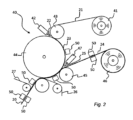
図1を参照すると、パッケージ容器を形成し、充填し、シールするように構成された包装機10が図示されている。包装機10は、典型的には、包装材料の平面状のウェブ20を閉鎖したパッケージ30に変形させるための多数の連続したステーションを含む。
With reference to FIG. 1, a
ウェブ状の包装材料20は、包装・充填機10に装填される。巻き出された包装材料20は、形成、充填、及びシールのために包装材料を準備するために、様々なステーションを通して連続的に移送される。このようなステーションは、例えば、長手方向ストリップアプリケータ、及び滅菌ユニット(図示せず)を含んでもよい。
A web of
充填のために、包装材料20はチューブに変形され、液体食品が無菌雰囲気でチューブ状の包装材料に充填されることを保証する無菌室12に運ばれる。包装材料20は、例えば形成リングを用いて徐々に変形され、チューブ状の形状に形成される。
For filling, the
チューブ状の包装材料20は長手方向にシールされ、液体食品は充填パイプ14によってチューブ状の包装材料20に充填される。最後に、横方向シールユニット16が、チューブ状包装材料20の閉鎖された下端と同時に閉鎖された上端が形成されるように、チューブ状包装材料の閉鎖を行う。また、シールユニット16は、完成したパッケージ30をチューブ状包装材料20から分離するために、横方向の切断を行う。切断されたパッケージ30は、さらに折り曲げ形成され、シールされて、立方体形状などの最終形状を獲得し得る。
The
また、包装機10は、包装材料20が包装機10を通して移送される際に、包装材料20のウェブの近くに配置される印刷ユニット50を備える。好ましくは、印刷ユニット50は、包装材料のウェブ20が平坦な位置、すなわち、チューブ形成の前に配置される。
The
印刷ユニット50は制御ユニット52に接続されており、その結果、印刷ユニット50は、包装材料20のウェブが包装機10を通って走行する際に、RFIDアンテナ100を異なる位置に印刷するように構成されている。RFIDアンテナ100は、好ましくは、グラフェンベースの導電性物質を用いて印刷される。
The
しかしながら、他の導電性物質を使用することも可能であり、特に、RFIDアンテナを印刷するために導電性インクを使用することも可能である。導電性インクは、炭素ベース(例えば、グラフェン又はカーボンナノチューブ)、金属ナノ粒子ベース(例えば、AG、Al)、又は有機系(例えば、Sigma Aldrich社のPlexcore OC AQ-1250)であり得る。金属ナノ粒子ベースのインクは使いやすく、市販されているが、液体食品包装との適合性の観点から、やはり炭素ベースの物質が好ましい可能性がある。 However, it is also possible to use other conductive materials, in particular conductive inks for printing the RFID antenna. The conductive inks can be carbon-based (e.g. graphene or carbon nanotubes), metal nanoparticle-based (e.g. AG, Al) or organic-based (e.g. Plexcore OC AQ-1250 from Sigma Aldrich). Metal nanoparticle-based inks are easy to use and commercially available, but again carbon-based materials may be preferred in terms of compatibility with liquid food packaging.
印刷ユニット50は、包装材料20の幅を横切って延びる細長い本体として示されている。しかしながら、印刷ユニット50は、RFIDアンテナ100を包装材料20+に印刷できるかぎり、多くの異なる形状及びサイズで実現できることを理解すべきである。
The
印刷ユニット50は、本実施形態では、RFIDアンテナ100を包装材料20の外面に印刷するように配置されているが、印刷に使用される物質によっては、印刷ユニット50は、RFIDアンテナ100を包装材料20の内面に印刷するように配置することも可能である。
In this embodiment, the
RFIDアンテナ100は、包装材料20の固定された、すなわち予め決められた位置に配置される。図4を参照して後で説明するように、包装材料20には折り目線などの特徴が設けられており、これにより、印刷ユニット50及び関連する制御ユニット52は、最終的なパッケージ30上でもRFIDアンテナ100が正しく配置されるように、印刷されたRFIDアンテナ100をこれらの特徴に対する所望の位置に正確に配置することができる。これは、RFIDチップがチップアプリケータによって適用される場合にも当てはまり、制御ユニット52(又は、チップアプリケータの動作を制御するように構成されている、いずれかの他の制御ユニット)は、RFIDアンテナに対するRFIDチップの位置を正確に制御するように構成されている。
The
したがって、RFIDアンテナ100は、包装材料20が包装機10を通して移送されるときに、包装材料20に適用されてもよい。
Thus, the
別の実施形態が図2に示されており、RFIDアンテナ100は、包装材料20の製造中に既に、すなわち包装材料20が包装機10に供給される前に、包装材料20に印刷される。
Another embodiment is shown in FIG. 2, in which the
図2には、包装材料変換ユニット40の一例が示されている。包装材料変換ユニット40は、マガジンリール41から供給されるアルミニウム箔ウェブ21を、押出機42から供給される熱可塑性材料22に予備積層するという概念に基づいているが、ここに提示される実施形態は、アルミニウム箔を持たないチルド製品の包装材料にも特に適し得ることに留意すべきである。したがって、図2の例は、1つの選択肢としてのみ捉えられるべきである。実際には、より複雑でなく、金属を含まない包装材料が、本明細書に記載されている技術的解決策にとって、はるかにより好ましい場合がある。
In FIG. 2, an example of a packaging
包装材料20の製造は、アルミニウム箔ウェブ21がマガジンリール41から払い出され、ニップローラ43及び下流に配置されたさらなるニップローラ45と接触し、それらと同期して回転する冷却ローラ44と接触するニップローラ43の上に導かれるように進行する。同時に、溶融又は半溶融の熱可塑性材料、例えばポリエチレンの連続フィルム22が押出機42によって押し出され、このプラスチックフィルムは、いわゆるニップ、すなわちニップローラ43と冷却ローラ44との間の接触点に導かれる。溶融又は半溶融の熱可塑性フィルム22は、このような例では、アルミニウム箔ウェブ21と冷却ローラ44の表面との間に収容され、それによってプラスチック-アルミニウム箔積層体23が形成される。
The production of the
別のマガジンリール46からは、紙又は板材のコア層ウェブ24が払い出され、ニップローラ45上に導かれて冷却ローラ44と接触する。第2の押出機47の助けを借りて、第2のニップローラ45と冷却ローラ44との間に連続したプラスチックフィルム25が押し出され、この場合、押し出されたポリエチレンのプラスチックフィルム25は、形成されたプラスチック-アルミニウム箔積層体23のアルミニウム箔側とコア層24との間に収容される。そして、第2のニップローラ45と冷却ローラ44との間で圧縮されることにより、コア層24と積層体23とが一体化され、複合包装材料積層体20が形成される。なお、包装材料20を形成するために、上述した変換プロセスに加えて、プラスチック材料の外層26やプラスチック材料の内層27を加えてもよい。
From another
図1を参照して記載した印刷ユニット50は、包装材料変換ユニット40の様々な位置に配置されてもよい。したがって、複数の印刷ユニット50が図2に示されているが、1つの場所に、1つの印刷ユニット50のみで必要とされる場合もあることを理解すべきである。
The
例えば、印刷ユニット50は、RFIDアンテナ100が積層前のコア層24の外側に印刷されるように、又は、積層前のコア層24の内側に印刷されるように配置されてもよい。印刷ユニット50の他の可能な位置は、図2に示されている。
For example, the
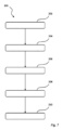
結果として得られる包装材料20の一例を、図3に断面で示す。RFIDアンテナ100は、変換プロセス中の印刷ユニット50の位置に応じて、異なる材料層間の界面のいずれか、すなわち、層27の外面側、層27と22の間、層22と21の間、層21と25の間、層25と24の間、層24と26の間、又は層26の外面側に配置することができる。
An example of the resulting
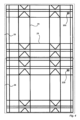
次に、図4に目を向けると、包装材料20の一例が示されている。包装材料20は、例えば、図1に示すような包装機10によって使用されるように、連続的なウェブの形態で提供される。ウェブは、一連のセグメント28を含み、各セグメント28は、後に個々のパッケージ30を形成するために使用される。図4では、2つのセグメント28が示されている。各セグメント28は、複数の折り目線29を有し、また、各セグメント28は、印刷ユニット50によって印刷されるRFIDアンテナ100を備えている。
Turning now to FIG. 4, an example of a
したがって、図4の包装材料20は、図1の印刷ユニット50の下流側の位置から、或いは図2の包装材料変換ユニット40による製造終了後に得ることができる。
The
図5に、グラフェンベースのRFIDアンテナ100の一例が示されている。アンテナ100を除いて、RFIDチップ110がアンテナ100に取り付けられている。RFIDチップ110は、RFIDアンテナ100が印刷された後であれば、いつでも取り付けることができる。図6では、グラフェンベースの導電性RFIDアンテナ100の別の例が示されている。ここでは、RFIDアンテナ100は、必ずしもRFIDチップに接続されておらず、1つ又は複数の共振回路120がアンテナ110の近くに印刷されている。好ましくは、これらの共振回路120も、印刷ユニット50によって、同じグラフェンベースの導電性物質を用いて印刷される。各共振回路120がエネルギーを吸収するため、アンテナ応答における共振周波数でエネルギー損失が発生する。16個の共振回路を有する図示の例では、すべての共振回路が唯一のものである場合、216個の組み合わせがあり、これをデジタルデータ表現に使用することができる。
In FIG. 5, an example of a graphene-based
印刷されたRFIDアンテナ100は、それによってRFIDタグを形成し、又はその一部を形成する。従来、RFIDタグは、アンテナ100とチップ110の2つの部分で構成される。RFIDアンテナ100は、本明細書の文脈では、グラフェンベースの材料によって形成され、特定の形状を有する平面導体である。一方、チップ110は、アンテナ100に接続された0.5mm2程度の小型の集積回路である。アンテナ100が包装材料20上に直接印刷されていることにより、RFIDタグを専用の基板上に製造し、それを最終的な包装材料上に適用しなければならないという追加の製造ステップは必要ない。RFIDアンテナ100を印刷するために使用されるグラフェンベースの導電性物質は、好ましくはインクの形態であり、それにより、標準的な機器(インクジェット技術など)を使用することができる。グラフェンベースの導電性物質は、グラフェン又は酸化グラフェンを1つ又は複数の層に含む。好ましくは、グラフェンベースの導電性物質は、グラフェン又は酸化グラフェンのフレークの分散液を含み、これにより、グラフェンベースの物質を印刷することができ、且つ、得られるRFIDアンテナ100がグラフェンベースの物質の導電性分布によって形成されるようになっている。
The printed
また、グラフェンベースの導電性インクは、上述したように、変換ユニット40において、包装材料20に直接アンテナ100を印刷することを可能にする。グラフェンベースの物質を印刷に使用することの利点の1つは、金属インクを使用した場合に比べて、アンテナ100の厚さを大幅に減らすことができることである。さらに、グラフェンは食品安全性にも優れている。
Graphene-based conductive inks also allow the
アンテナ100にRFIDチップ110を接続する場合は、印刷後にチップ110をアンテナ100に適用して接続することが好ましい。
When connecting an
また、提案した印刷技術は、図6を参照して上で提案したように、チップレスRFIDの使用も可能にする。このような実施形態では、アンテナ100はいかなるチップにも接続されず、それによって、統合されたRFID技術のより速い、迅速な生産を可能にする。
The proposed printing technique also enables the use of chipless RFID, as proposed above with reference to FIG. 6. In such an embodiment, the
同じグラフェンベースの導電性インクを使って、アンテナ100の近くにいくつかの形状を印刷することができる。これらの形状は共振器として機能し、その形状に応じて静電容量、インダクタンス、及び共振周波数によって特徴づけられる。唯一の形状を印刷することで、唯一のスペクトルシグネチャを持つチップレスRFIDタグを印刷する可能性もまたもたらされる。このように、パッケージ(又は包装材料)のRFID識別は、包装材料上に集積回路がなくても、グラフェンベースの物質とそれを包装材料上に直接印刷する能力のみを利用して可能である。
The same graphene-based conductive ink can be used to print several shapes near the
一実施形態では、感知機能を追加することで、チップレスRFIDアンテナ100を改良することができる。いくつかの共振回路120を有する図6の実施形態から出発して、これらの共振回路の特性パラメータを、いくつかの環境変数に応じて変化するように構成することができる。一例として、共振回路120の1つを、包装材料20の温度が10℃を超えて上昇した場合に昇華するように構成されたポリマーインクで覆うことができる。この場合、共振回路120の静電容量が変化し、その結果、共振周波数も変化する。換言すると、そのようなアプローチは、パッケージ30のコールドチェーン監視に使用されると好ましい。
In one embodiment, the
次に、図7を参照して、包装材料20を提供するための方法200について記載する。この方法200は、包装材料処理ユニットを介して包装材料20のウェブを供給する第1のステップ202と、前記包装材料20の目標位置を決定するステップ204と、前記目標位置にRFIDアンテナ100を印刷するように印刷ユニット50を制御するステップ206とを含み、RFIDアンテナ100の印刷に使用される材料はグラフェンベースの導電性物質である。
7, a
RFIDアンテナ100を印刷するように印刷ユニット50を制御するステップ206は、アンテナ100に隣接する1つ又は複数の共振回路120を印刷するステップ208も含むことができる。
Step 206 of controlling the
任意選択的に、方法200は、1つ又は複数の共振回路120をある物質でコーティングするステップ208を含んでもよく、この物質は、共振回路120の共振周波数を変更するように構成されている。
Optionally, the
また、任意選択的に、方法200は、RFIDチップをアンテナ100に取り付けるステップ210を含んでいてもよい。
Optionally,
本発明の様々な実施形態を記載し、示してきたが、本発明はこれらに限定されるものではなく、以下の特許請求の範囲で定義される主題の範囲内で他の方法で具現化することもできることが、以上の記載から導かれる。 Although various embodiments of the invention have been described and illustrated, it follows from the above that the invention is not limited thereto and may be embodied in other ways within the scope of the subject matter defined in the following claims.
Claims (18)
包装材料処理ユニットを通して包装材料のウェブを供給すること、
前記包装材料の目標位置を決定すること、
前記目標位置にRFIDアンテナを印刷するように印刷ユニットを制御すること、
を含み、
前記RFIDアンテナの印刷に使用される材料は導電性物質であり、
前記RFIDアンテナを前記目標位置に印刷するように印刷ユニットを制御することは、前記RFIDアンテナに隣接する1つ又は複数の共振回路を印刷することをさらに含み、
前記1つ又は複数の共振回路を第1の物質でコーティングすることをさらに含み、前記第1の物質は、前記共振回路の共振周波数を変化させるように構成されている、
方法。 1. A method of providing packaging material, comprising the steps of:
feeding a web of packaging material through a packaging material processing unit ;
determining a target location for the packaging material ;
controlling a printing unit to print an RFID antenna at said target location ;
Including ,
The material used for printing the RFID antenna is a conductive material;
controlling a printing unit to print the RFID antenna at the target location further includes printing one or more resonant circuits adjacent to the RFID antenna;
and further comprising coating the one or more resonant circuits with a first material, the first material configured to change a resonant frequency of the resonant circuits.
method.
前記RFIDアンテナ(100)に隣接して配置された少なくとも1つの共振回路(120)と、を含み、
前記少なくとも1つの共振回路は、第1の物質でコーティングされ、前記第1の物質は、前記共振回路の共振周波数を変化させるように構成されている、
包装材料(20)。 A packaging material (20) comprising a plurality of layers (21-27) which together form a laminate configured to preserve liquid food contents when the packaging material (20) is formed into a package container (30), said packaging material (20) including at least one RFID antenna (100) which is printed as a web of said packaging material (20) is fed through a packaging material processing unit (10, 40);
at least one resonant circuit (120) disposed adjacent to said RFID antenna (100);
the at least one resonant circuit is coated with a first material, the first material being configured to change a resonant frequency of the resonant circuit.
Packaging material (20).
請求項12に記載の包装材料。 The RFID antenna (100) is formed of a graphene-based conductive material.
13. The packaging material of claim 12.
請求項12~15のいずれか一項に記載の包装材料。 said RFID antenna (100) being located at any of the interfaces between different material layers depending on the position of the printing unit (50) during the converting process;
The packaging material according to any one of claims 12 to 15 .
Applications Claiming Priority (3)
| Application Number | Priority Date | Filing Date | Title |
|---|---|---|---|
| EP19181464.9 | 2019-06-20 | ||
| EP19181464 | 2019-06-20 | ||
| PCT/EP2020/066199 WO2020254185A1 (en) | 2019-06-20 | 2020-06-11 | A method for a packaging material |
Publications (2)
| Publication Number | Publication Date |
|---|---|
| JP2022537392A JP2022537392A (en) | 2022-08-25 |
| JP7586844B2 true JP7586844B2 (en) | 2024-11-19 |
Family
ID=66999721
Family Applications (1)
| Application Number | Title | Priority Date | Filing Date |
|---|---|---|---|
| JP2021575903A Active JP7586844B2 (en) | 2019-06-20 | 2020-06-11 | Method for packaging materials |
Country Status (6)
| Country | Link |
|---|---|
| US (1) | US12049338B2 (en) |
| EP (1) | EP3754555B1 (en) |
| JP (1) | JP7586844B2 (en) |
| CN (2) | CN213168825U (en) |
| ES (1) | ES2938046T3 (en) |
| WO (1) | WO2020254185A1 (en) |
Families Citing this family (2)
| Publication number | Priority date | Publication date | Assignee | Title |
|---|---|---|---|---|
| WO2020254185A1 (en) * | 2019-06-20 | 2020-12-24 | Tetra Laval Holdings & Finance S.A. | A method for a packaging material |
| ES2965907T3 (en) * | 2020-11-06 | 2024-04-17 | Becton Dickinson France | Coating bag for packaging at least one medical product |
Citations (4)
| Publication number | Priority date | Publication date | Assignee | Title |
|---|---|---|---|---|
| JP2011525863A (en) | 2008-03-14 | 2011-09-29 | テトラ ラバル ホールデイングス エ フイナンス ソシエテ アノニム | Packaging laminate, method for producing packaging laminate, and packaging container produced therefrom |
| WO2018216686A1 (en) | 2017-05-26 | 2018-11-29 | 株式会社村田製作所 | Packaging paperboard and method for manufacturing same |
| JP2019502620A (en) | 2015-10-07 | 2019-01-31 | ケンブリッジ エンタープライズ リミティッド | Layered material and processing method thereof |
| JP2021506686A (en) | 2017-12-21 | 2021-02-22 | ストラ エンソ オーワイジェイ | How to manufacture a color piece with an RFID tag |
Family Cites Families (20)
| Publication number | Priority date | Publication date | Assignee | Title |
|---|---|---|---|---|
| JPH0417514Y2 (en) * | 1987-05-13 | 1992-04-20 | ||
| US6943678B2 (en) * | 2000-01-24 | 2005-09-13 | Nextreme, L.L.C. | Thermoformed apparatus having a communications device |
| US20030151028A1 (en) * | 2002-02-14 | 2003-08-14 | Lawrence Daniel P. | Conductive flexographic and gravure ink |
| FI114121B (en) * | 2002-11-04 | 2004-08-13 | Rafsec Oy | Procedure for producing product detector and product detector |
| DE102004007457A1 (en) * | 2004-02-13 | 2005-09-01 | Man Roland Druckmaschinen Ag | In-line printing of intelligent packaging films has an initial station to print a conductive circuit, as an antenna, followed by four-color printing stations and a chip application station as a radio frequency identity tag |
| DE102004007458A1 (en) * | 2004-02-13 | 2005-09-01 | Man Roland Druckmaschinen Ag | Process for the production of RFID labels |
| FR2898999A1 (en) * | 2006-03-21 | 2007-09-28 | St Microelectronics Sa | METHOD FOR MANUFACTURING AN RFID ELECTRONIC LABEL |
| KR101539125B1 (en) * | 2007-10-10 | 2015-07-23 | 코비오 인코포레이티드 | Wireless devices including printed integrated circuitry and methods for manufacturing and using the same |
| US7653982B2 (en) * | 2007-11-16 | 2010-02-02 | Xerox Corporation | Individually unique hybrid printed antennae for chipless RFID applications |
| EP2071496A1 (en) * | 2007-12-13 | 2009-06-17 | Mondi AG | Method for manufacturing flexible packaging with RFID transponder |
| CN201980563U (en) * | 2010-06-24 | 2011-09-21 | 瑞化股份有限公司 | Shrink wrap construction with wireless identification |
| RU2579348C2 (en) * | 2010-12-29 | 2016-04-10 | Тетра Лаваль Холдингз Энд Файнэнс С.А. | Method of production of packaging material provided with repeating pattern made with printing ink |
| TR201806881T4 (en) * | 2011-12-29 | 2018-06-21 | Tetra Laval Holdings & Finance | Packaging chambers produced from the packaging layer as well as a packaging layer for a packaging chamber. |
| WO2015099378A1 (en) * | 2013-12-26 | 2015-07-02 | 주식회사 엘지화학 | Graphene production method, and graphene dispersion composition |
| CN103965697A (en) * | 2014-05-23 | 2014-08-06 | 武汉大学 | Corrosion-resistant carbon conductive ink and application thereof in manufacturing RFID (radio frequency identification) antenna |
| GB2554952A (en) * | 2016-10-17 | 2018-04-18 | Parkside Flexibles Europe Ltd | Electronic identifier for packaging |
| CN108764429A (en) * | 2018-03-07 | 2018-11-06 | 厦门信达光电物联科技研究院有限公司 | A kind of RFID electronic label and preparation method thereof of frangible anti-transfer |
| CN208156705U (en) * | 2018-04-28 | 2018-11-27 | 华瑞墨石丹阳有限公司 | A kind of vulnerable graphite alkene RFID tag |
| US20200002560A1 (en) * | 2018-06-29 | 2020-01-02 | Chung-Ping Lai | Conductive ink for use in manufacturing radio frequency identification (rfid) tag antenna and method for manufacturing rfid tag antenna |
| WO2020254185A1 (en) * | 2019-06-20 | 2020-12-24 | Tetra Laval Holdings & Finance S.A. | A method for a packaging material |
-
2020
- 2020-06-11 WO PCT/EP2020/066199 patent/WO2020254185A1/en not_active Ceased
- 2020-06-11 EP EP20179507.7A patent/EP3754555B1/en active Active
- 2020-06-11 JP JP2021575903A patent/JP7586844B2/en active Active
- 2020-06-11 US US17/596,812 patent/US12049338B2/en active Active
- 2020-06-11 ES ES20179507T patent/ES2938046T3/en active Active
- 2020-06-22 CN CN202021164753.3U patent/CN213168825U/en active Active
- 2020-06-22 CN CN202010572314.4A patent/CN112109985B/en active Active
Patent Citations (4)
| Publication number | Priority date | Publication date | Assignee | Title |
|---|---|---|---|---|
| JP2011525863A (en) | 2008-03-14 | 2011-09-29 | テトラ ラバル ホールデイングス エ フイナンス ソシエテ アノニム | Packaging laminate, method for producing packaging laminate, and packaging container produced therefrom |
| JP2019502620A (en) | 2015-10-07 | 2019-01-31 | ケンブリッジ エンタープライズ リミティッド | Layered material and processing method thereof |
| WO2018216686A1 (en) | 2017-05-26 | 2018-11-29 | 株式会社村田製作所 | Packaging paperboard and method for manufacturing same |
| JP2021506686A (en) | 2017-12-21 | 2021-02-22 | ストラ エンソ オーワイジェイ | How to manufacture a color piece with an RFID tag |
Also Published As
| Publication number | Publication date |
|---|---|
| CN112109985A (en) | 2020-12-22 |
| US12049338B2 (en) | 2024-07-30 |
| US20220161957A1 (en) | 2022-05-26 |
| EP3754555B1 (en) | 2022-11-23 |
| EP3754555A1 (en) | 2020-12-23 |
| ES2938046T3 (en) | 2023-04-04 |
| WO2020254185A1 (en) | 2020-12-24 |
| CN213168825U (en) | 2021-05-11 |
| JP2022537392A (en) | 2022-08-25 |
| CN112109985B (en) | 2025-04-11 |
Similar Documents
| Publication | Publication Date | Title |
|---|---|---|
| CN104555086B (en) | Composite packaging material, method of making the same, and sealed packaging made therefrom | |
| JP6087821B2 (en) | Method for manufacturing packaging material for retort packaging | |
| JP6878397B2 (en) | Methods and systems for forming packages | |
| CN103561945B (en) | Packaging material with detectable markings for the manufacture of packaging containers based on boxboard or paperboard | |
| JP7586844B2 (en) | Method for packaging materials | |
| WO2009131496A1 (en) | Inside creasing on a packaging laminate, a packaging container made from the packaging laminate, and a method for producing the packaging laminate | |
| CN205186890U (en) | Multi -layer packaging material , sheet group and by sealed package of its manufacturing | |
| US20190337666A1 (en) | Sleeve Blank, Package Sleeve, Package and Method for Manufacturing a Sleeve Blank, a Package Sleeve and a Package | |
| AU2003289167B2 (en) | Laminate material, laminate material manufacturing method, laminate material heat-sealing method, and package container | |
| CN100374287C (en) | Method for producing packaging laminated material | |
| WO2018145881A1 (en) | A packaging material and a method for providing a packaging material | |
| JP2014507308A (en) | Method for manufacturing package material provided with repeated pattern of printing ink | |
| JPH0671831A (en) | Laminated packaging material with good fragrance barrier properties and method of making same | |
| CN100542794C (en) | Method for producing packaging laminate blanks and blanks and packaging containers produced thereby | |
| CN118647498A (en) | Packaging material and method for producing such packaging material | |
| US20070271881A1 (en) | Packaging and Filling Machine | |
| CN204414787U (en) | Produce the production line with the compound package material of different Quick Response Code | |
| US11731415B2 (en) | Process to manufacture multilayer laminated packaging material | |
| JP6913740B2 (en) | Packaging material containing magnetized parts and method of magnetizing the material | |
| JP2001191411A (en) | Manufacturing method of semi-material for paper container and packaging material for paper container |
Legal Events
| Date | Code | Title | Description |
|---|---|---|---|
| A621 | Written request for application examination |
Free format text: JAPANESE INTERMEDIATE CODE: A621 Effective date: 20230530 |
|
| A131 | Notification of reasons for refusal |
Free format text: JAPANESE INTERMEDIATE CODE: A131 Effective date: 20240423 |
|
| A977 | Report on retrieval |
Free format text: JAPANESE INTERMEDIATE CODE: A971007 Effective date: 20240424 |
|
| A601 | Written request for extension of time |
Free format text: JAPANESE INTERMEDIATE CODE: A601 Effective date: 20240723 |
|
| A521 | Request for written amendment filed |
Free format text: JAPANESE INTERMEDIATE CODE: A523 Effective date: 20240924 |
|
| TRDD | Decision of grant or rejection written | ||
| A01 | Written decision to grant a patent or to grant a registration (utility model) |
Free format text: JAPANESE INTERMEDIATE CODE: A01 Effective date: 20241022 |
|
| A61 | First payment of annual fees (during grant procedure) |
Free format text: JAPANESE INTERMEDIATE CODE: A61 Effective date: 20241107 |
|
| R150 | Certificate of patent or registration of utility model |
Ref document number: 7586844 Country of ref document: JP Free format text: JAPANESE INTERMEDIATE CODE: R150 |