JP7586801B2 - Fuel Cell Systems - Google Patents
Fuel Cell Systems Download PDFInfo
- Publication number
- JP7586801B2 JP7586801B2 JP2021164929A JP2021164929A JP7586801B2 JP 7586801 B2 JP7586801 B2 JP 7586801B2 JP 2021164929 A JP2021164929 A JP 2021164929A JP 2021164929 A JP2021164929 A JP 2021164929A JP 7586801 B2 JP7586801 B2 JP 7586801B2
- Authority
- JP
- Japan
- Prior art keywords
- power generation
- fuel cell
- storage device
- state variable
- power
- Prior art date
- Legal status (The legal status is an assumption and is not a legal conclusion. Google has not performed a legal analysis and makes no representation as to the accuracy of the status listed.)
- Active
Links
Images


Classifications
-
- Y—GENERAL TAGGING OF NEW TECHNOLOGICAL DEVELOPMENTS; GENERAL TAGGING OF CROSS-SECTIONAL TECHNOLOGIES SPANNING OVER SEVERAL SECTIONS OF THE IPC; TECHNICAL SUBJECTS COVERED BY FORMER USPC CROSS-REFERENCE ART COLLECTIONS [XRACs] AND DIGESTS
- Y02—TECHNOLOGIES OR APPLICATIONS FOR MITIGATION OR ADAPTATION AGAINST CLIMATE CHANGE
- Y02E—REDUCTION OF GREENHOUSE GAS [GHG] EMISSIONS, RELATED TO ENERGY GENERATION, TRANSMISSION OR DISTRIBUTION
- Y02E60/00—Enabling technologies; Technologies with a potential or indirect contribution to GHG emissions mitigation
- Y02E60/30—Hydrogen technology
- Y02E60/50—Fuel cells
Landscapes
- Fuel Cell (AREA)
Description
本発明は、燃料電池システムに関する。 The present invention relates to a fuel cell system.
燃料電池システムとして、多段階発電制御により燃料電池の発電を制御するものがある。多段階発電制御とは、燃料電池の発電電力が供給される蓄電装置の状態変数(蓄電装置の電圧や充電率など)が増加している場合、蓄電装置の状態変数と複数の充電側閾値との比較結果に応じた目標発電電力により燃料電池の発電を制御し、蓄電装置の状態変数が減少している場合、蓄電装置の状態変数と複数の放電側閾値との比較結果に応じた目標発電電力により燃料電池の発電を制御するものである。関連する技術として、特許文献1がある。
Some fuel cell systems use multi-stage power generation control to control the power generation of the fuel cell. Multi-stage power generation control involves controlling the power generation of the fuel cell with a target power generation level according to the results of comparing the state variables of the power storage device with multiple charging thresholds when the state variables of the power storage device (such as the voltage and charging rate of the power storage device) to which the power generated by the fuel cell is supplied are increasing, and controlling the power generation of the fuel cell with a target power generation level according to the results of comparing the state variables of the power storage device with multiple discharging thresholds when the state variables of the power storage device are decreasing. Related technology is described in
また、多段階発電制御の他に無段階発電制御として、蓄電装置の状態変数に応じた目標発電電力により燃料電池の発電を制御するものがある。 In addition to multi-stage power generation control, there is also stepless power generation control, which controls the power generation of a fuel cell based on a target power generation output according to the state variables of the power storage device.
しかしながら、多段階発電制御と無段階発電制御とを併用する場合、無段階発電制御から多段階発電制御に遷移するときに適切な閾値が利用されていないと、無段階発電制御から多段階発電制御に遷移した後すぐに目標発電電力が変化することで燃料電池の電圧が変動し燃料電池を劣化させてしまうおそれがある。例えば、無段階発電制御から多段階発電制御に遷移するときに蓄電装置の状態変数が減少しているにもかかわらず、充電側閾値が利用されて目標発電電力が求められてしまうと、その後、すぐに、放電側閾値が利用されて目標発電電力が変化するおそれがある。 However, when multi-stage power generation control and stepless power generation control are used together, if an appropriate threshold is not used when transitioning from stepless power generation control to multi-stage power generation control, the target power generation may change immediately after transitioning from stepless power generation control to multi-stage power generation control, causing fluctuations in the fuel cell voltage and deteriorating the fuel cell. For example, if the charge-side threshold is used to calculate the target power generation even though the state variable of the power storage device has decreased when transitioning from stepless power generation control to multi-stage power generation control, then the discharge-side threshold may be used immediately thereafter and the target power generation may change.
本発明の一側面に係る目的は、多段階発電制御と無段階発電制御とを併用する燃料電池システムにおいて、無段階発電制御から多段階発電制御に遷移する際の燃料電池の電圧の変動を抑制することである。 The object of one aspect of the present invention is to suppress fluctuations in the fuel cell voltage when transitioning from stepless power generation control to multi-stage power generation control in a fuel cell system that uses both multi-stage power generation control and stepless power generation control.
本発明に係る一つの形態である燃料電池車両は、蓄電装置と、前記蓄電装置に電力を供給する燃料電池と、多段階発電制御時において、前記蓄電装置の状態変数が増加している場合、前記蓄電装置の状態変数と複数の充電側閾値との比較結果に応じた目標発電電力により前記燃料電池の発電を制御し、前記蓄電装置の状態変数が減少している場合、前記蓄電装置の状態変数と複数の放電側閾値との比較結果に応じた目標発電電力により前記燃料電池の発電を制御し、無段階発電制御時において、前記蓄電装置の状態変数に応じた目標発電電力により前記燃料電池の発電を制御する制御部とを備える。 A fuel cell vehicle according to one embodiment of the present invention includes a power storage device, a fuel cell that supplies power to the power storage device, and a control unit that, during multi-stage power generation control, controls the power generation of the fuel cell with a target power generation power corresponding to a result of comparing the state variable of the power storage device with multiple charging side thresholds when the state variable of the power storage device is increasing, controls the power generation of the fuel cell with a target power generation power corresponding to a result of comparing the state variable of the power storage device with multiple discharging side thresholds when the state variable of the power storage device is decreasing, and controls the power generation of the fuel cell with the target power generation power corresponding to the state variable of the power storage device during stepless power generation control.
前記制御部は、前記無段階発電制御から前記多段階発電制御に遷移するとき、前記蓄電装置の状態変数が増加している場合、前記蓄電装置の状態変数と前記複数の充電側閾値との比較結果に応じた目標発電電力により前記燃料電池の発電を制御し、前記無段階発電制御から前記多段階発電制御に遷移するとき、前記蓄電装置の状態変数が減少している場合、前記蓄電装置の状態変数と前記複数の放電側閾値との比較結果に応じた目標発電電力により前記燃料電池の発電を制御する。 When transitioning from the stepless power generation control to the multi-stage power generation control, if the state variable of the power storage device is increasing, the control unit controls the power generation of the fuel cell with a target power generation power corresponding to the result of comparing the state variable of the power storage device with the multiple charge-side thresholds, and when transitioning from the stepless power generation control to the multi-stage power generation control, if the state variable of the power storage device is decreasing, the control unit controls the power generation of the fuel cell with a target power generation power corresponding to the result of comparing the state variable of the power storage device with the multiple discharge-side thresholds.
これにより、無段階発電制御から多段階発電制御に遷移する際の蓄電装置の状態変数の変動に伴う目標発電電力の変動を抑制することができるため、燃料電池の電圧の変動を抑えることができ、燃料電池の劣化を抑制することができる。 This makes it possible to suppress fluctuations in the target power generation that accompany fluctuations in the state variables of the power storage device when transitioning from stepless power generation control to multi-stage power generation control, thereby suppressing fluctuations in the fuel cell voltage and suppressing deterioration of the fuel cell.
また、前記制御部は、前記多段階発電制御から前記無段階発電制御に遷移するときの前記蓄電装置の状態変数が前記無段階発電制御から前記多段階発電制御に遷移するときの前記蓄電装置の状態変数より大きい場合、前記蓄電装置の状態変数と前記複数の充電側閾値との比較結果に応じた目標発電電力により前記燃料電池の発電を制御し、前記多段階発電制御から前記無段階発電制御に遷移するときの前記蓄電装置の状態変数が前記無段階発電制御から前記多段階発電制御に遷移するときの前記蓄電装置の状態変数より小さい場合、前記蓄電装置の状態変数と前記複数の放電側閾値との比較結果に応じた目標発電電力により前記燃料電池の発電を制御するように構成してもよい。 The control unit may be configured to control the power generation of the fuel cell with a target power generation power corresponding to a result of comparing the state variable of the power storage device with the multiple charging side thresholds when the state variable of the power storage device at the time of transition from the multi-stage power generation control to the stepless power generation control is greater than the state variable of the power storage device at the time of transition from the stepless power generation control to the multi-stage power generation control, and to control the power generation of the fuel cell with a target power generation power corresponding to a result of comparing the state variable of the power storage device with the multiple discharging side thresholds when the state variable of the power storage device at the time of transition from the multi-stage power generation control to the stepless power generation control is smaller than the state variable of the power storage device at the time of transition from the stepless power generation control to the multi-stage power generation control.
本発明によれば、多段階発電制御と無段階発電制御とを併用する燃料電池システムにおいて、無段階発電制御から多段階発電制御に遷移する際の燃料電池の電圧の変動を抑制することができる。 According to the present invention, in a fuel cell system that uses both multi-stage power generation control and stepless power generation control, it is possible to suppress fluctuations in the fuel cell voltage when transitioning from stepless power generation control to multi-stage power generation control.
以下図面に基づいて実施形態について詳細を説明する。 The following describes the embodiment in detail with reference to the drawings.
図1は、実施形態の燃料電池車両の一例を示す図である。 Figure 1 shows an example of a fuel cell vehicle according to an embodiment.
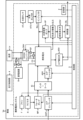
図1に示す燃料電池システム1は、車両Veに搭載され、負荷Loなどに電力を供給する。なお、車両Veは、フォークリフトなどの産業車両や自動車などとする。また、負荷Loは、走行用モータを駆動するインバータなどとする。
The
また、燃料電池システム1は、燃料電池FCと、水素タンクHTと、水素タンク弁HTVと、インジェクタINJと、気液分離機GLSと、水素循環ポンプHPと、排気排水弁EDVと、希釈器DILと、エアコンプレッサACPと、エア調圧弁ARVと、エアシャット弁ASVとを備える。
The
また、燃料電池システム1は、さらに、ラジエタRと、ファンFと、ウォータポンプWPと、インタークーラICと、DCDCコンバータCNVと、蓄電装置Bと、電流センサSifと、電圧センサSvfと、電流センサSibと、電圧センサSvbと、記憶部2と、制御部3とを備える。
The
燃料電池FCは、互いに直列接続される複数の燃料電池セルにより構成される燃料電池スタックであり、燃料ガス(水素ガスなど)に含まれる水素と酸化剤ガス(空気など)に含まれる酸素との電気化学反応により電気を発生させる。 A fuel cell FC is a fuel cell stack consisting of multiple fuel cell cells connected in series with each other, and generates electricity through an electrochemical reaction between the hydrogen contained in the fuel gas (such as hydrogen gas) and the oxygen contained in the oxidant gas (such as air).
水素タンクHTは、燃料ガスの貯蔵容器である。水素タンクHTに貯蔵された燃料ガスは水素タンク弁HTV及びインジェクタINJを介して燃料電池FCに供給される。 The hydrogen tank HT is a storage container for fuel gas. The fuel gas stored in the hydrogen tank HT is supplied to the fuel cell FC via the hydrogen tank valve HTV and the injector INJ.
水素タンク弁HTVは、燃料電池FCに供給される燃料ガスを減圧する。 The hydrogen tank valve HTV reduces the pressure of the fuel gas supplied to the fuel cell FC.
インジェクタINJは、燃料電池FCに供給される燃料ガスの流量を調整する。 The injector INJ adjusts the flow rate of fuel gas supplied to the fuel cell FC.
気液分離機GLSは、燃料電池FCから排出される燃料ガスと液水とを分離する。 The gas-liquid separator GLS separates the fuel gas and liquid water discharged from the fuel cell FC.
水素循環ポンプHPは、気液分離機GLSにより分離された燃料ガスを燃料電池FCに再度供給する。 The hydrogen circulation pump HP supplies the fuel gas separated by the gas-liquid separator GLS back to the fuel cell FC.
排気排水弁EDVは、気液分離機GLSにより分離された液水を希釈器DILに送る。希釈器DILに送られた液水は、希釈器DIL内のタンクに溜まる。また、燃料電池FCから排出された燃料ガスと酸化剤ガスは希釈器DILで合流し、燃料電池システム1の外部に排出される。
The exhaust drain valve EDV sends the liquid water separated by the gas-liquid separator GLS to the diluter DIL. The liquid water sent to the diluter DIL accumulates in a tank inside the diluter DIL. In addition, the fuel gas and oxidant gas discharged from the fuel cell FC join together in the diluter DIL and are discharged outside the
エアコンプレッサACPは、燃料電池システム1の周囲に存在する酸化剤ガスを圧縮しインタークーラIC及びエアシャット弁ASVを介して燃料電池FCに供給する。なお、エアコンプレッサACPの圧縮率は、燃料電池FCの下流に設けられるエア調圧弁ARVの開度を調節することで制御される。
The air compressor ACP compresses the oxidant gas present around the
インタークーラICは、圧縮により高温になった酸化剤ガスをインタークーラICに流れる冷却水などの冷媒と熱交換させる。 The intercooler IC exchanges heat between the oxidant gas, which has been heated by compression, and a refrigerant such as cooling water flowing through the intercooler IC.
エアシャット弁ASVは、燃料電池FCに供給される酸化剤ガスを遮断する。なお、車両Veのイグニッションキーがオンしているとき、エアシャット弁ASVは常に全開になっているものとする。 The air shutoff valve ASV blocks the oxidant gas supplied to the fuel cell FC. When the ignition key of the vehicle Ve is on, the air shutoff valve ASV is always fully open.
エア調圧弁ARVは、燃料電池FCに供給される酸化剤ガスの圧力や流量を調整する。 The air pressure regulator valve ARV adjusts the pressure and flow rate of the oxidant gas supplied to the fuel cell FC.
ラジエタRは、燃料電池FCの発熱により温められた冷媒を外気と熱交換させる。 The radiator R exchanges heat between the refrigerant, which is heated by the heat generated by the fuel cell FC, and the outside air.
ファンFは、ラジエタRの放熱量を上昇させる。 Fan F increases the amount of heat dissipated by radiator R.
ウォータポンプWPは、ラジエタRにより冷却された冷媒をインタークーラICを介して燃料電池FCに供給する。 The water pump WP supplies the refrigerant cooled by the radiator R to the fuel cell FC via the intercooler IC.
DCDCコンバータCNVは、燃料電池FCの後段に接続され、燃料電池FCから出力される電圧Vfを所定の電圧に変換する。DCDCコンバータCNVから出力される電力は、負荷Lo、水素循環ポンプHPなどの補機、及び蓄電装置Bに供給される。例えば、DCDCコンバータCNVは、燃料電池FCの電圧を48[V]に変換する。DCDCコンバータCNVから出力される電力の一部は、48[V]系の補機である水素循環ポンプHP、エアコンプレッサACP、及びウォータポンプWPに供給される。また、DCDCコンバータCNVにより48[V]に変換された電圧は、他のDCDCコンバータ(不図示)により12[V]の電圧に変換される。他のDCDCコンバータから出力される電力は、12[V]系の補機であるファンF、エアシャット弁ASV、及びエア調圧弁ARVに供給される。 The DCDC converter CNV is connected to the rear of the fuel cell FC and converts the voltage Vf output from the fuel cell FC to a predetermined voltage. The power output from the DCDC converter CNV is supplied to the load Lo, auxiliary equipment such as the hydrogen circulation pump HP, and the power storage device B. For example, the DCDC converter CNV converts the voltage of the fuel cell FC to 48 [V]. A part of the power output from the DCDC converter CNV is supplied to the 48 [V] system auxiliary equipment such as the hydrogen circulation pump HP, the air compressor ACP, and the water pump WP. In addition, the voltage converted to 48 [V] by the DCDC converter CNV is converted to a voltage of 12 [V] by another DCDC converter (not shown). The power output from the other DCDC converter is supplied to the 12 [V] system auxiliary equipment such as the fan F, the air shutoff valve ASV, and the air pressure regulating valve ARV.
蓄電装置Bは、キャパシタなどにより構成され、DCDCコンバータCNVと負荷Loとの間に接続されている。DCDCコンバータCNVから出力される電力と、48[V]系の補機及び12[V]系の補機にそれぞれ供給される電力の合計値との差に相当する供給電力が、燃料電池システム1の外部(例えば、車両Veに搭載される走行制御部4)から要求される要求電力より大きい場合、その供給電力のうち、要求電力分の電力が負荷Loに供給されるとともに、残りの電力が蓄電装置Bに供給される。DCDCコンバータCNVから蓄電装置Bに電力が供給されると、蓄電装置Bが充電され蓄電装置Bの状態変数Sが増加する。また、DCDCコンバータCNVから出力される電力と、48[V]系の補機及び12[V]系の補機にそれぞれ供給される電力の合計値との差に相当する供給電力が、燃料電池システム1の外部から要求される要求電力より小さい場合、その供給電力が負荷Loに供給されるとともに、足りない分の電力が蓄電装置Bから負荷Loに供給される。蓄電装置Bから負荷Loに電力が供給されると、蓄電装置Bが放電され蓄電装置Bの状態変数Sが減少する。なお、状態変数Sとは、蓄電装置Bの充電率[%](蓄電装置Bの満充電容量に対する残容量の割合)、または、蓄電装置Bに電流が流れていないときの蓄電装置Bの開回路電圧[V]、または、蓄電装置Bに電流が流れているときの蓄電装置Bの閉回路電圧[V]、または、蓄電装置Bに流れる電流の積算値[Ah]などとする。
The storage device B is composed of a capacitor and is connected between the DCDC converter CNV and the load Lo. If the supply power corresponding to the difference between the power output from the DCDC converter CNV and the total value of the power supplied to the 48 [V] system auxiliary equipment and the 12 [V] system auxiliary equipment is greater than the required power required from the outside of the fuel cell system 1 (for example, the driving control unit 4 mounted on the vehicle Ve), the required power of the supply power is supplied to the load Lo and the remaining power is supplied to the storage device B. When power is supplied from the DCDC converter CNV to the storage device B, the storage device B is charged and the state variable S of the storage device B increases. In addition, if the supply power corresponding to the difference between the power output from the DCDC converter CNV and the total value of the power supplied to the 48 [V] system auxiliary equipment and the 12 [V] system auxiliary equipment is smaller than the required power required from the outside of the
電流センサSifは、シャント抵抗やホール素子などにより構成され、燃料電池FCからDCDCコンバータCNVに流れる電流Ifを検出し、その検出した電流Ifを制御部3に送る。
The current sensor Sif is composed of a shunt resistor, a Hall element, etc., and detects the current If flowing from the fuel cell FC to the DCDC converter CNV and sends the detected current If to the
電圧センサSvfは、分圧抵抗などにより構成され、燃料電池FCから出力される電圧Vfを検出し、その検出した電圧Vfを制御部3に送る。
The voltage sensor Svf is composed of a voltage dividing resistor, etc., detects the voltage Vf output from the fuel cell FC, and sends the detected voltage Vf to the
電流センサSibは、シャント抵抗やホール素子などにより構成され、DCDCコンバータCNVから蓄電装置Bに流れる電流Ibまたは蓄電装置Bから負荷Loに流れる電流Ibを検出し、その検出した電流Ibを制御部3に送る。
The current sensor Sib is composed of a shunt resistor, a Hall element, etc., and detects the current Ib flowing from the DCDC converter CNV to the storage device B or the current Ib flowing from the storage device B to the load Lo, and sends the detected current Ib to the
電圧センサSvbは、分圧抵抗などにより構成され、蓄電装置Bの電圧Vbを検出し、その検出した電圧Vbを制御部3に送る。
The voltage sensor Svb is composed of a voltage dividing resistor and the like, detects the voltage Vb of the storage device B, and sends the detected voltage Vb to the
記憶部2は、RAM(Random Access Memory)やROM(Read Only Memory)などにより構成され、後述する閾値Cth10などを記憶する。 The storage unit 2 is configured with RAM (Random Access Memory) and ROM (Read Only Memory), and stores the threshold value Cth10 described below.
制御部3は、マイクロコンピュータなどにより構成される。
The
また、制御部3は、無段階発電制御要求がオフであるとき、多段階発電制御により燃料電池FCの発電電力を制御し、無段階発電制御要求がオンであるとき、無段階発電制御により燃料電池FCの発電電力を制御する。例えば、制御部3は、負荷Loが高負荷状態でないと判定しているとき、無段階発電制御要求をオフにし、負荷Loが高負荷状態であると判定しているとき、無段階発電制御要求をオンにする。例えば、制御部3は、車両Veが登り坂を走行していない(車両Veが勾配を有する坂を上っていない)と判定しているとき、負荷Loが高負荷状態でないと判定し、車両Veが登り坂を走行している(車両Veが勾配を有する坂を上っている)と判定しているとき、負荷Loが高負荷状態であると判定する。また、車両Veが登り坂を走行しているか否かの判定方法については後述する。
When the stepless power generation control request is off, the
すなわち、制御部3は、無段階発電制御要求がオフであるとき、多段階発電制御として、蓄電装置Bの状態変数Sに応じて目標発電電力Ptを段階的に変化させる。
In other words, when the stepless power generation control request is off, the
また、制御部3は、無段階発電制御要求がオフであるとき、多段階発電制御として、燃料電池FCの発電電力が目標発電電力Ptに追従するように、48[V]系の補機や12[V]系の補機の動作を制御することで、燃料電池FCの発電電力を制御する。例えば、制御部3は、無段階発電制御要求がオフであるとき、多段階発電制御として、PI(Proportional-Integral)制御により、燃料電池FCの発電電力と目標発電電力Ptとの差がゼロになるように、48[V]系の補機や12[V]系の補機の動作を制御する。
When the stepless power generation control request is off, the
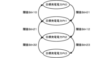
ここで、図2は、多段階発電制御による燃料電池FCの発電制御を説明するための図である。なお、閾値Sth10、閾値Sth21、及び閾値Sth32を充電側閾値とし、閾値Sth01、閾値Sth12、及び閾値Sth23を放電側閾値とする。また、閾値Sth23<閾値Sth32<閾値Sth12<閾値Sth21<閾値Sth01<閾値Sth10とする。また、目標発電電力Pt0<目標発電電力Pt1<目標発電電力Pt2<目標発電電力Pt3とし、目標発電電力Pt0をゼロとする。また、目標発電電力Pt3と目標発電電力Pt2との差、目標発電電力Pt2と目標発電電力Pt1との差、目標発電電力Pt1と目標発電電力Pt0との差は、それぞれ、一定値でもよいし、異なる値でもよい。目標発電電力Ptが大きくなるほど、燃料電池FCから出力される電力が大きくなり、目標発電電力Ptが小さくなるほど、燃料電池FCから出力される電力が小さくなるものとする。また、目標発電電力Ptが目標発電電力Pt0になると、燃料電池FCの発電が停止して燃料電池FCから出力される電力がゼロになるものとする。 Here, FIG. 2 is a diagram for explaining the power generation control of the fuel cell FC by multi-stage power generation control. Thresholds Sth10, Sth21, and Sth32 are charge side thresholds, and thresholds Sth01, Sth12, and Sth23 are discharge side thresholds. Threshold Sth23<threshold Sth32<threshold Sth12<threshold Sth21<threshold Sth01<threshold Sth10. Target power generation Pt0<target power generation Pt1<target power generation Pt2<target power generation Pt3, and target power generation Pt0 is zero. The difference between the target power generation Pt3 and the target power generation Pt2, the difference between the target power generation Pt2 and the target power generation Pt1, and the difference between the target power generation Pt1 and the target power generation Pt0 may each be a constant value or may be a different value. The larger the target power generation Pt, the greater the power output from the fuel cell FC, and the smaller the target power generation Pt, the smaller the power output from the fuel cell FC. In addition, when the target power generation Pt reaches the target power generation Pt0, power generation by the fuel cell FC stops and the power output from the fuel cell FC becomes zero.
制御部3は、無段階発電制御要求がオフであるとき、多段階発電制御として、蓄電装置Bの状態変数Sが閾値Sth32より大きくなると、目標発電電力Ptを目標発電電力Pt3から目標発電電力Pt2に変化させ、蓄電装置Bの状態変数Sが閾値Sth21より大きくなると、目標発電電力Ptを目標発電電力Pt2から目標発電電力Pt1に変化させ、蓄電装置Bの状態変数Sが閾値Sth10より大きくなると、目標発電電力Ptを目標発電電力Pth1から目標発電電力Pth0に変化させる。すなわち、制御部3は、無段階発電制御要求がオフであるとき、多段階発電制御として、蓄電装置Bの状態変数Sが大きくなるほど、燃料電池FCから出力される電力が段階的に小さくなるように、燃料電池FCの発電を制御する。
When the stepless power generation control request is off, the
また、制御部3は、無段階発電制御要求がオフであるとき、多段階発電制御として、蓄電装置Bの状態変数Sが閾値Sth01より小さくなると、目標発電電力Ptを目標発電電力Pt0から目標発電電力Pt1に変化させ、蓄電装置Bの状態変数Sが閾値Sth12より小さくなると、目標発電電力Ptを目標発電電力Pt1から目標発電電力Pt2に変化させ、蓄電装置Bの状態変数Sが閾値Sth23より小さくなると、目標発電電力Ptを目標発電電力Pt2から目標発電電力Pt3に変化させる。すなわち、制御部3は、無段階発電制御要求がオフであるとき、多段階発電制御として、蓄電装置Bの状態変数Sが小さくなるほど、燃料電池FCから出力される電力が段階的に大きくなるように、燃料電池FCの発電を制御する。
When the stepless power generation control request is off, the
このように、蓄電装置Bの状態変数Sに応じて燃料電池FCから出力される電力を段階的に変化させているため、燃料電池FCから出力される電圧の単位時間あたりの変動回数を抑制することができ、燃料電池FCの劣化を抑制することができる。 In this way, the power output from the fuel cell FC is changed in stages according to the state variable S of the power storage device B, so that the number of fluctuations per unit time in the voltage output from the fuel cell FC can be reduced, and deterioration of the fuel cell FC can be suppressed.
一方、制御部3は、無段階発電制御要求がオンであるとき、無段階発電制御として、蓄電装置Bの状態変数Sに応じて目標発電電力Ptを線形的に制御する。例えば、制御部3は、蓄電装置Bの状態変数Sが、無段階発電制御要求がオフからオンに切り替わったときの蓄電装置Bの状態変数Sに維持されるように、目標発電電力Ptを線形的に変化させる。または、制御部3は、蓄電装置Bの状態変数Sが閾値Sth10より大きくならないように、かつ、燃料電池システム1から負荷Loに供給される電力が走行制御部4から要求される電力に追従するように、目標発電電力Ptを線形的に変化させる。
On the other hand, when the stepless power generation control request is on, the
また、制御部3は、無段階発電制御要求がオフからオンに切り替わる直前において状態変数Sと閾値Sthとの比較結果により求めた目標発電電力Ptを、無段階発電制御要求がオンしているときの目標発電電力Ptの下限値に設定するように構成してもよい。
The
これにより、無段階発電制御から多段階発電制御に戻ったときの目標発電電力Ptの変動幅を抑えることができるため、補機の動作制御の安定性を向上させることができ、燃料電池システム1全体の動作制御の安定性を向上させることができる。
This reduces the fluctuation range of the target power generation Pt when returning from stepless power generation control to multi-stage power generation control, thereby improving the stability of the operational control of the auxiliary equipment and the stability of the operational control of the entire
また、制御部3は、無段階発電制御から多段階発電制御に遷移する場合において、蓄電装置Bの状態変数Sが増加しているとき、蓄電装置Bの状態変数Sと複数の充電側閾値との比較結果に応じた目標発電電力Ptにより燃料電池FCの発電を制御する。
In addition, when transitioning from stepless power generation control to multi-stage power generation control, when the state variable S of the storage device B is increasing, the
また、制御部3は、無段階発電制御から多段階発電制御に遷移する場合において、蓄電装置Bの状態変数Sが減少しているとき、蓄電装置Bの状態変数Sと複数の放電側閾値との比較結果に応じた目標発電電力Ptにより燃料電池FCの発電を制御する。
In addition, when transitioning from stepless power generation control to multi-stage power generation control, when the state variable S of the storage device B is decreasing, the
また、制御部3は、無段階発電制御要求がオンになると、負荷Loの状態を示すフラグを立ち上げ、無段階発電制御要求がオフになると、フラグを立ち下げる。
In addition, when the stepless power generation control request is turned on, the
ここで、図3は、フラグに関する制御部3の動作の一例を示すフローチャートである。なお、図3に示すフローチャートは制御タイミング毎に繰り返し実行されるものとする。
Here, FIG. 3 is a flowchart showing an example of the operation of the
制御部3は、無段階発電制御要求がオフであるときで(ステップS11:No)、かつ、フラグが立ち下がっていないと判定すると(ステップS12:Yes)、フラグを立ち下げる(ステップS13)。
When the
一方、制御部3は、無段階発電制御要求がオンであるときで(ステップS11:Yes)、かつ、フラグが立ち上がっていないと判定すると(ステップS14:Yes)、フラグを立ち上げる(ステップS15)。
On the other hand, when the stepless power generation control request is on (step S11: Yes) and the
なお、制御部3は、無段階発電制御要求がオフであるときで(ステップS11:No)、かつ、フラグが立ち下がっていると判定すると(ステップS12:No)、または、無段階発電制御要求がオンであるときで(ステップS11:Yes)、かつ、フラグが立ち上がっていると判定すると(ステップS14:No)、次の制御タイミングまでフラグの状態を維持する。
When the stepless power generation control request is OFF (step S11: No) and the
また、図4は、燃料電池FCの発電制御に関する制御部3の動作の一例を示すフローチャートである。なお、図4に示すフローチャートは制御タイミング毎に繰り返し実行されるものとする。
FIG. 4 is a flowchart showing an example of the operation of the
まず、制御部3は、無段階発電制御要求がオンであるときで(ステップS21:Yes)、かつ、今回の制御タイミングがフラグの立ち上がりタイミングと一致する場合(ステップS22:Yes)、今回の制御タイミングにおける蓄電装置Bの状態変数Sを状態変数S0として記憶部2に記憶する(ステップS23)。
First, when the stepless power generation control request is on (step S21: Yes) and the current control timing coincides with the timing when the flag is raised (step S22: Yes), the
また、制御部3は、無段階発電制御要求がオンであるときで(ステップS21:Yes)、かつ、今回の制御タイミングがフラグの立ち上がりタイミングと一致しない場合、すなわち、すでにフラグが立ち上がっている場合(ステップS22:No)、無段階発電制御により燃料電池FCの発電を制御する(ステップS24)。
In addition, when the stepless power generation control request is on (step S21: Yes) and the current control timing does not match the timing when the flag is raised, i.e., the flag has already been raised (step S22: No), the
一方、制御部3は、無段階発電制御要求がオフであるときで(ステップS21:No)、かつ、今回の制御タイミングがフラグの立ち下がりタイミングと一致する場合(ステップS25:Yes)、今回の制御タイミングにおける蓄電装置Bの状態変数Sを状態変数S1として記憶部2に記憶する(ステップS26)。
On the other hand, when the stepless power generation control request is off (step S21: No) and the current control timing coincides with the falling timing of the flag (step S25: Yes), the
次に、制御部3は、記憶部2に記憶されている状態変数S0が記憶部2に記憶されている状態変数S1より大きい場合(ステップS27:Yes)、多段階発電制御において利用される閾値として放電側閾値を選択する(ステップS28)。すなわち、制御部3は、多段階発電制御から無段階発電制御に遷移するときの蓄電装置Bの状態変数S0が無段階発電制御から多段階発電制御に遷移するときの蓄電装置Bの状態変数S1より大きく、無段階発電制御から多段階発電制御に遷移する際に蓄電装置Bの状態変数Sが減少傾向にある場合、蓄電装置Bの状態変数Sと複数の放電側閾値との比較結果に応じた目標発電電力Ptにより燃料電池FCの発電を制御する。
Next, when the state variable S0 stored in the memory unit 2 is greater than the state variable S1 stored in the memory unit 2 (step S27: Yes), the
一方、制御部3は、状態変数S0が状態変数S1より小さい場合(ステップS27:No)、多段階発電制御において利用される閾値として充電側閾値を選択する(ステップS29)。すなわち、制御部3は、多段階発電制御から無段階発電制御に遷移するときの蓄電装置Bの状態変数S0が無段階発電制御から多段階発電制御に遷移するときの蓄電装置Bの状態変数S1より小さく、無段階発電制御から多段階発電制御に遷移する際に蓄電装置Bの状態変数Sが増加傾向にある場合、蓄電装置Bの状態変数Sと複数の充電側閾値との比較結果に応じた目標発電電力Ptにより燃料電池FCの発電を制御する。
On the other hand, when the state variable S0 is smaller than the state variable S1 (step S27: No), the
そして、制御部3は、無段階発電制御要求がオフであるときで(ステップS21:No)、かつ、今回の制御タイミングがフラグの立ち下がりタイミングと一致しない場合、すなわち、すでにフラグが立ち下がっている場合(ステップS25:No)、ステップS28で選択した放電側閾値またはステップS29で選択した充電側閾値を利用して多段階発電制御により燃料電池FCの発電電力を制御する(ステップS30)。
Then, when the stepless power generation control request is off (step S21: No) and the current control timing does not coincide with the flag falling timing, i.e., the flag has already fallen (step S25: No), the
ここで、例えば、状態変数Sを蓄電装置Bの開回路電圧[V]とし、閾値Sth21を42[V]とし、閾値Sth12を39[V]とし、記憶部2に状態変数S0として43[V]が記憶され、記憶部2に状態変数S1として37[V]が記憶されている場合を想定する。 Here, for example, assume that state variable S is the open circuit voltage [V] of storage device B, threshold value Sth21 is 42 [V], threshold value Sth12 is 39 [V], 43 [V] is stored as state variable S0 in memory unit 2, and 37 [V] is stored as state variable S1 in memory unit 2.
既存の燃料電池システムでは、無段階発電制御から多段階発電制御に遷移した直後、充電側閾値として閾値Sth21(42[V])を利用して目標発電電力Ptを求めてしまうおそれがある。すなわち、既存の燃料電池システムでは、無段階発電制御から多段階発電制御に遷移した直後、状態変数S0(43[V])が閾値Sth21(42[V])より大きいと判断して目標発電電力Pt1を求めてしまうおそれがある。そのため、既存の燃料電池システムでは、その後の多段階発電制御時において、状態変数S1(37[V])が閾値Sth12(39[V])より小さくなったと判断すると、目標発電電力Ptを目標発電電力Pt1から目標発電電力Pt2に変化させてしまう。燃料電池FCの一般的な特性として、出力電力が大きくなるほど、電圧が低くなる特性がある。よって、目標発電電力Ptは、無段階発電制御における目標発電電力から目標発電電力Pt1となり、そして目標発電電力Pt2に変化することは、電位変動が生じることになり、燃料電池FCが劣化する原因となってしまう。 In the existing fuel cell system, immediately after the transition from stepless power generation control to multi-stage power generation control, there is a risk that the target power generation Pt is calculated using the threshold value Sth21 (42 [V]) as the charging side threshold. In other words, in the existing fuel cell system, immediately after the transition from stepless power generation control to multi-stage power generation control, there is a risk that the state variable S0 (43 [V]) is determined to be greater than the threshold value Sth21 (42 [V]) and the target power generation Pt1 is calculated. Therefore, in the existing fuel cell system, when it is determined that the state variable S1 (37 [V]) has become smaller than the threshold value Sth12 (39 [V]) during the subsequent multi-stage power generation control, the target power generation Pt is changed from the target power generation Pt1 to the target power generation Pt2. A general characteristic of a fuel cell FC is that the higher the output power, the lower the voltage. Therefore, when the target power generation Pt changes from the target power generation in stepless power generation control to the target power generation Pt1 and then to the target power generation Pt2, a potential fluctuation occurs, which can cause the fuel cell FC to deteriorate.
このように、既存の燃料電池システムでは、無段階発電制御から多段階発電制御に遷移するとき、状態変数Sが減少傾向であるにもかかわらず、充電側閾値を利用していると、無段階発電制御から多段階発電制御に遷移した後において、目標発電電力Ptを変化させてしまうおそれがある。 Thus, in existing fuel cell systems, when transitioning from stepless power generation control to multi-stage power generation control, even though the state variable S has a decreasing tendency, if the charging side threshold is used, there is a risk that the target power generation power Pt will change after transitioning from stepless power generation control to multi-stage power generation control.
一方、実施形態の燃料電池システム1では、無段階発電制御から多段階発電制御に遷移するとき、状態変数S0(43[V])が状態変数S1(37[V])より大きいと判断すると、すなわち、状態変数Sが減少傾向であると判定すると、多段階発電制御時の放電側閾値として閾値Sth12(39[V])を利用する。そのため、実施形態の燃料電池システム1では、無段階発電制御から多段階発電制御に遷移した直後、状態変数S1(37[V])が閾値Sth12(39[V])より小さいと判定すると、目標発電電力Pt2を求めることができ、その後の多段階発電制御において、目標発電電力Ptの変動を抑制することができる。
On the other hand, in the
このように実施形態の燃料電池システム1では、無段階発電制御から多段階発電制御に遷移するとき、蓄電装置Bの状態変数Sが減少傾向にある場合、蓄電装置Bの状態変数Sと複数の放電側閾値との比較結果に応じた目標発電電力Ptにより燃料電池FCの発電を制御する構成である。
In this manner, in the
また、実施形態の燃料電池システム1では、無段階発電制御から多段階発電制御に遷移するとき、蓄電装置Bの状態変数Sが増加傾向にある場合、蓄電装置Bの状態変数Sと複数の充電側閾値との比較結果に応じた目標発電電力Ptにより燃料電池FCの発電を制御する構成である。
In addition, in the
これにより、無段階発電制御から多段階発電制御に遷移する際の蓄電装置Bの状態変数Sの変動に伴う目標発電電力Ptの変動を抑制することができるため、燃料電池FCの出力電圧の変動を抑えることができ、燃料電池FCの劣化を抑制することができる。 This makes it possible to suppress fluctuations in the target power generation Pt that accompany fluctuations in the state variable S of the storage device B when transitioning from stepless power generation control to multi-stage power generation control, thereby suppressing fluctuations in the output voltage of the fuel cell FC and suppressing deterioration of the fuel cell FC.
また、実施形態の燃料電池システム1によれば、無段階発電制御から多段階発電制御に遷移するときに最適な目標発電電力Ptを求めることができるため、補機駆動によるNV(Noise Vibration)性や官能性の悪化を抑制することができる。
In addition, according to the
<車両Veが登り坂を走行しているか否かの判定方法>
制御部3は、走行制御部4から送られてくる情報に基づいて、車両Veが登り坂を走行しているか否かの判定を行う。
<Method of determining whether the vehicle Ve is traveling uphill>
The
走行制御部4は、負荷Loの動作を制御することで、車両Veの走行や荷役などを制御する。 The driving control unit 4 controls the operation of the load Lo, thereby controlling the driving and loading and unloading of the vehicle Ve.
また、走行制御部4は、運転者によるアクセルペダルの操作量をアクセル開度として制御部3に送る。
The driving control unit 4 also sends the amount of accelerator pedal operation by the driver to the
また、走行制御部4は、負荷Loを動作させるために必要な電力を要求電力として制御部3に送る。例えば、走行制御部4は、運転者の指示に基づく負荷Loの動作制御から予想される負荷Loの消費電力を、要求電力とする。
The driving control unit 4 also sends the power required to operate the load Lo to the
また、走行制御部4は、車両Veの速度及び加速度を制御部3に送る。例えば、走行制御部4は、(走行用モータの回転数[rpm]×タイヤ外径[m]×円周率)/(ギア比×減速比)の計算結果を、速度Vとする。また、走行制御部4は、1秒間あたりの速度の変化量を、加速度とする。
The driving control unit 4 also sends the speed and acceleration of the vehicle Ve to the
制御部3は、走行制御部4から送られてくる、アクセル開度、要求電力、速度、及び加速度に基づいて、車両Veが登り坂を走行しているか否かを判定する。
The
一般に、登り坂の勾配[%]が大きくなるほど、走行用モータで消費される電力が大きくなる傾向がある。特に、車両Veが産業車両である場合、車両Veの重量が比較的大きくなるため、上り坂の勾配が大きくなるほど、走行用モータで消費される電力がさらに大きくなる傾向がある。また、登り坂の勾配が大きくなるほど、車両Veの速度が小さくなる傾向がある。また、車両Veが登り坂を走行している場合、平坦路を走行している場合に比べて、車両Veの速度が小さくなるため、平坦路と同じ速度に保とうとする運転者の心理によりアクセルペダルの操作量が比較的大きくなる傾向がある。また、車両Veが登り坂を走行している場合、車両Veの速度が一定速度になり易いため、車両Veの加速度が比較的小さくなる傾向がある。すなわち、車両Veが登り坂を走行しているとき、要求電力及びアクセル開度が比較的大きくなるとともに、速度及び加速度が比較的小さくなる。 In general, the greater the gradient [%] of the uphill road, the greater the power consumed by the driving motor. In particular, when the vehicle Ve is an industrial vehicle, the weight of the vehicle Ve is relatively large, so the greater the gradient of the uphill road, the greater the power consumed by the driving motor. Also, the greater the gradient of the uphill road, the slower the speed of the vehicle Ve tends to be. Also, when the vehicle Ve is traveling uphill, the speed of the vehicle Ve is slower than when traveling on a flat road, so the driver's psychology of trying to maintain the same speed as on a flat road tends to make the accelerator pedal operation relatively large. Also, when the vehicle Ve is traveling uphill, the speed of the vehicle Ve tends to be constant, so the acceleration of the vehicle Ve tends to be relatively small. In other words, when the vehicle Ve is traveling uphill, the required power and accelerator opening are relatively large, and the speed and acceleration are relatively small.
そこで、制御部3は、要求電力が所定要求電力以上であり、かつ、アクセル開度が所定アクセル開度以上であり、かつ、速度が所定速度以下であり、かつ、加速度が所定加速度以下である場合、車両Veが登り坂を走行していると判定する。また、制御部3は、要求電力が所定要求電力より小さい場合、または、アクセル開度が所定アクセル開度より小さい場合、または、速度が所定速度より大きい場合、または、加速度が所定加速度より大きい場合、車両Veが登り坂を走行していない(車両Veが平坦な道または下り坂を走行している)と判定する。
Therefore, the
なお、制御部3は、要求電力、アクセル開度、速度、及び加速度の4つのパラメータのうちの少なくとも1つのパラメータを用いて、車両Veが登り坂を走行しているか否かを判定するように構成してもよい。
The
また、走行制御部4において、車両Veが登り坂を走行しているか否かを判定し、その判定結果を制御部3に送るように構成してもよい。
The driving control unit 4 may also be configured to determine whether the vehicle Ve is traveling uphill and send the determination result to the
また、本発明は、以上の実施の形態に限定されるものでなく、本発明の要旨を逸脱しない範囲内で種々の改良、変更が可能である。 Furthermore, the present invention is not limited to the above-described embodiments, and various improvements and modifications are possible without departing from the spirit of the present invention.
<変形例>
上記実施形態の燃料電池システム1は、車両Veに搭載される負荷Loに電力を供給する発電機として構成しているが、燃料電池システム1を、商用電源と協働して燃料電池システム1の外部に設けられる負荷に電力を供給する定置発電機として構成してもよい。その場合、制御部が負荷の要求電力量を監視し、要求電力量が所定電力閾値以上、かつ所定時間以上継続場合に、高負荷状態であると判断するのが好ましい。
<Modification>
Although the
1 燃料電池システム
2 記憶部
3 制御部
4 走行制御部
Ve 車両
Lo 負荷
FC 燃料電池
HT 水素タンク
HTV 水素タンク弁
INJ インジェクタ
GLS 気液分離機
HP 水素循環ポンプ
EDV 排気排水弁
DIL 希釈器
ACP エアコンプレッサ
ARV エア調圧弁
ASV エアシャット弁
R ラジエタ
F ファン
WP ウォータポンプ
IC インタークーラ
CNV DCDCコンバータ
B 蓄電装置
Sif、Sib 電流センサ
Svf、Svb 電圧センサ
REFERENCE SIGNS
Claims (2)
前記蓄電装置に電力を供給する燃料電池と、
多段階発電制御時において、前記蓄電装置の状態変数が増加している場合、前記蓄電装置の状態変数と複数の充電側閾値との比較結果に応じた目標発電電力により前記燃料電池の発電を制御し、前記蓄電装置の状態変数が減少している場合、前記蓄電装置の状態変数と複数の放電側閾値との比較結果に応じた目標発電電力により前記燃料電池の発電を制御し、無段階発電制御時において、前記蓄電装置の状態変数に応じた目標発電電力により前記燃料電池の発電を制御する制御部と、
を備え、
前記制御部は、
前記無段階発電制御から前記多段階発電制御に遷移するとき、前記蓄電装置の状態変数が増加している場合、前記蓄電装置の状態変数と前記複数の充電側閾値との比較結果に応じた目標発電電力により前記燃料電池の発電を制御し、
前記無段階発電制御から前記多段階発電制御に遷移するとき、前記蓄電装置の状態変数が減少している場合、前記蓄電装置の状態変数と前記複数の放電側閾値との比較結果に応じた目標発電電力により前記燃料電池の発電を制御する
ことを特徴とする燃料電池システム。 A power storage device;
a fuel cell for supplying power to the power storage device;
a control unit which, during multi-stage power generation control, when a state variable of the power storage device is increasing, controls power generation of the fuel cell with a target power generation power corresponding to a result of comparing the state variable of the power storage device with a plurality of charging-side threshold values, and, when a state variable of the power storage device is decreasing, controls power generation of the fuel cell with a target power generation power corresponding to a result of comparing the state variable of the power storage device with a plurality of discharging-side threshold values, and, during stepless power generation control, controls power generation of the fuel cell with the target power generation power corresponding to the state variable of the power storage device;
Equipped with
The control unit is
when transitioning from the stepless power generation control to the multi-step power generation control, if a state variable of the power storage device is increasing, controlling power generation of the fuel cell with a target power generation electric power according to a comparison result between the state variable of the power storage device and the plurality of charging-side threshold values;
a control unit for controlling power generation of the fuel cell based on a target power generation output corresponding to a comparison result between the state variable of the power storage device and the plurality of discharge side threshold values when a transition is made from the stepless power generation control to the multi-stage power generation control and a state variable of the power storage device is decreasing.
前記制御部は、
前記多段階発電制御から前記無段階発電制御に遷移したときの前記蓄電装置の状態変数を第1状態変数として記憶部に記憶した後、前記無段階発電制御から前記多段階発電制御に遷移したときの前記蓄電装置の状態変数を第2状態変数として前記記憶部に記憶し、
前記第1状態変数が前記第2状態変数より大きい場合、前記蓄電装置の状態変数と前記複数の放電側閾値との比較結果に応じた目標発電電力により前記燃料電池の発電を制御し、
前記第1状態変数が前記第2状態変数より小さい場合、前記蓄電装置の状態変数と前記複数の充電側閾値との比較結果に応じた目標発電電力により前記燃料電池の発電を制御する
ことを特徴とする燃料電池システム。 2. The fuel cell system according to claim 1,
The control unit is
storing a state variable of the power storage device when the multi-stage power generation control is transitioned to the stepless power generation control as a first state variable in a storage unit, and then storing a state variable of the power storage device when the stepless power generation control is transitioned to the multi-stage power generation control as a second state variable in the storage unit;
When the first state variable is greater than the second state variable, power generation of the fuel cell is controlled based on a target power generation electric power corresponding to a result of comparison between the state variable of the power storage device and the plurality of discharge side threshold values;
When the first state variable is smaller than the second state variable, power generation of the fuel cell is controlled based on a target power generation amount corresponding to a result of comparison between the state variable of the power storage device and the plurality of charging-side threshold values.
A fuel cell system comprising:
Priority Applications (1)
| Application Number | Priority Date | Filing Date | Title |
|---|---|---|---|
| JP2021164929A JP7586801B2 (en) | 2021-10-06 | 2021-10-06 | Fuel Cell Systems |
Applications Claiming Priority (1)
| Application Number | Priority Date | Filing Date | Title |
|---|---|---|---|
| JP2021164929A JP7586801B2 (en) | 2021-10-06 | 2021-10-06 | Fuel Cell Systems |
Publications (2)
| Publication Number | Publication Date |
|---|---|
| JP2023055498A JP2023055498A (en) | 2023-04-18 |
| JP7586801B2 true JP7586801B2 (en) | 2024-11-19 |
Family
ID=86004108
Family Applications (1)
| Application Number | Title | Priority Date | Filing Date |
|---|---|---|---|
| JP2021164929A Active JP7586801B2 (en) | 2021-10-06 | 2021-10-06 | Fuel Cell Systems |
Country Status (1)
| Country | Link |
|---|---|
| JP (1) | JP7586801B2 (en) |
Citations (4)
| Publication number | Priority date | Publication date | Assignee | Title |
|---|---|---|---|---|
| JP2001325976A (en) | 2000-05-15 | 2001-11-22 | Toyota Motor Corp | Power supply using fuel cell and chargeable / dischargeable power storage unit |
| JP2006254610A (en) | 2005-03-11 | 2006-09-21 | Suzuki Motor Corp | Vehicle control device |
| JP2007202265A (en) | 2006-01-25 | 2007-08-09 | Omron Corp | Fuel cell system |
| JP2018073796A (en) | 2016-11-04 | 2018-05-10 | 株式会社豊田自動織機 | Fuel cell vehicle |
-
2021
- 2021-10-06 JP JP2021164929A patent/JP7586801B2/en active Active
Patent Citations (4)
| Publication number | Priority date | Publication date | Assignee | Title |
|---|---|---|---|---|
| JP2001325976A (en) | 2000-05-15 | 2001-11-22 | Toyota Motor Corp | Power supply using fuel cell and chargeable / dischargeable power storage unit |
| JP2006254610A (en) | 2005-03-11 | 2006-09-21 | Suzuki Motor Corp | Vehicle control device |
| JP2007202265A (en) | 2006-01-25 | 2007-08-09 | Omron Corp | Fuel cell system |
| JP2018073796A (en) | 2016-11-04 | 2018-05-10 | 株式会社豊田自動織機 | Fuel cell vehicle |
Also Published As
| Publication number | Publication date |
|---|---|
| JP2023055498A (en) | 2023-04-18 |
Similar Documents
| Publication | Publication Date | Title |
|---|---|---|
| JP7159929B2 (en) | fuel cell system | |
| JP3719229B2 (en) | Power supply | |
| WO2008004564A1 (en) | Electric power control of fuel cell vehicle | |
| US6684135B2 (en) | Control device for fuel cell vehicle | |
| US20080133076A1 (en) | Efficiency optimized hybrid operation strategy | |
| US6691810B2 (en) | Apparatus for controlling fuel cell vehicle | |
| US11165080B2 (en) | Fuel cell system | |
| JP2024068761A (en) | Fuel Cell Systems | |
| JP7564072B2 (en) | Fuel Cell Systems | |
| JP3871960B2 (en) | Fuel cell system and fuel cell vehicle | |
| JP2021019368A (en) | Hybrid vehicle | |
| JP2020102420A (en) | Fuel cell system | |
| JP7586801B2 (en) | Fuel Cell Systems | |
| US7315771B2 (en) | Control device for fuel cell vehicle | |
| JP2013062085A (en) | Fuel cell system | |
| US20050151508A1 (en) | Battery isolator | |
| US8097373B2 (en) | Fuel cell power supply device | |
| JP7663400B2 (en) | Fuel cell industrial vehicles and fuel cell systems | |
| US20240123841A1 (en) | Fuel cell system and fuel cell vehicle | |
| JP7564073B2 (en) | Fuel Cell Systems | |
| JP7569137B2 (en) | Fuel Cell Systems | |
| JP7646529B2 (en) | Fuel Cell Systems | |
| JP2005057929A (en) | Control device for fuel cell vehicle | |
| JP7834418B2 (en) | SOC control unit | |
| JP2023110672A (en) | Fuel cell system and charging method |
Legal Events
| Date | Code | Title | Description |
|---|---|---|---|
| A521 | Request for written amendment filed |
Free format text: JAPANESE INTERMEDIATE CODE: A523 Effective date: 20211028 |
|
| A621 | Written request for application examination |
Free format text: JAPANESE INTERMEDIATE CODE: A621 Effective date: 20240215 |
|
| A521 | Request for written amendment filed |
Free format text: JAPANESE INTERMEDIATE CODE: A523 Effective date: 20240308 |
|
| A977 | Report on retrieval |
Free format text: JAPANESE INTERMEDIATE CODE: A971007 Effective date: 20240828 |
|
| A131 | Notification of reasons for refusal |
Free format text: JAPANESE INTERMEDIATE CODE: A131 Effective date: 20240903 |
|
| A521 | Request for written amendment filed |
Free format text: JAPANESE INTERMEDIATE CODE: A523 Effective date: 20241021 |
|
| TRDD | Decision of grant or rejection written | ||
| A01 | Written decision to grant a patent or to grant a registration (utility model) |
Free format text: JAPANESE INTERMEDIATE CODE: A01 Effective date: 20241105 |
|
| A61 | First payment of annual fees (during grant procedure) |
Free format text: JAPANESE INTERMEDIATE CODE: A61 Effective date: 20241107 |
|
| R150 | Certificate of patent or registration of utility model |
Ref document number: 7586801 Country of ref document: JP Free format text: JAPANESE INTERMEDIATE CODE: R150 |