JP7586751B2 - Wind direction adjustment device - Google Patents
Wind direction adjustment device Download PDFInfo
- Publication number
- JP7586751B2 JP7586751B2 JP2021055474A JP2021055474A JP7586751B2 JP 7586751 B2 JP7586751 B2 JP 7586751B2 JP 2021055474 A JP2021055474 A JP 2021055474A JP 2021055474 A JP2021055474 A JP 2021055474A JP 7586751 B2 JP7586751 B2 JP 7586751B2
- Authority
- JP
- Japan
- Prior art keywords
- air distribution
- link
- wind
- air
- distribution body
- Prior art date
- Legal status (The legal status is an assumption and is not a legal conclusion. Google has not performed a legal analysis and makes no representation as to the accuracy of the status listed.)
- Active
Links
- 230000003014 reinforcing effect Effects 0.000 claims description 38
- 238000011144 upstream manufacturing Methods 0.000 claims description 21
- 230000007246 mechanism Effects 0.000 claims description 6
- 238000013459 approach Methods 0.000 claims description 5
- 239000012530 fluid Substances 0.000 claims description 5
- 230000007935 neutral effect Effects 0.000 description 6
- 238000009423 ventilation Methods 0.000 description 6
- 238000004891 communication Methods 0.000 description 5
- 230000001143 conditioned effect Effects 0.000 description 5
- 238000005452 bending Methods 0.000 description 4
- 230000000694 effects Effects 0.000 description 4
- 230000007480 spreading Effects 0.000 description 3
- 238000007664 blowing Methods 0.000 description 2
- 238000009434 installation Methods 0.000 description 2
- 230000004044 response Effects 0.000 description 2
- 230000000087 stabilizing effect Effects 0.000 description 2
- 238000004378 air conditioning Methods 0.000 description 1
- 230000008859 change Effects 0.000 description 1
- 238000001816 cooling Methods 0.000 description 1
- 238000010438 heat treatment Methods 0.000 description 1
- 238000003780 insertion Methods 0.000 description 1
- 230000037431 insertion Effects 0.000 description 1
- 230000002452 interceptive effect Effects 0.000 description 1
- 230000002787 reinforcement Effects 0.000 description 1
- 125000006850 spacer group Chemical group 0.000 description 1
Images


Landscapes
- Air-Flow Control Members (AREA)
- Air-Conditioning For Vehicles (AREA)
Description
本発明は、通路部内にフィンと配風体とを備える風向調整装置に関する。 The present invention relates to a wind direction adjustment device that has fins and a wind distribution body inside a passage section.
従来、自動車などの車両に用いられる空調装置において、吹き出す風向を調整する風向調整装置がある。風向調整装置は、空調風吹出装置、エアアウトレット、ベンチレータ、レジスタなどとも呼ばれ、例えばインストルメントパネルやセンタコンソール部などの車両の各部に設置されて、冷暖房による快適性能の向上に寄与している。 Conventionally, air conditioners used in vehicles such as automobiles include air direction adjustment devices that adjust the direction of the air being blown out. Air direction adjustment devices are also called air conditioner air outlet devices, air outlets, ventilators, registers, etc., and are installed in various parts of the vehicle, such as the instrument panel or center console, and contribute to improving comfort performance through heating and cooling.
通常、風向調整装置には、横方向及び縦方向に多数のルーバが配置されており、これらを連動して回動させることにより吹出口からの風の吹き出し方向を調整する。しかしながら、多数のルーバを連動させる構成の場合、部品点数が多く、また、通気抵抗が大きくなることにより、安価で簡素な構成とすることが困難であるとともに、配風性能の確保が容易でない。 Typically, a wind direction adjustment device has many louvers arranged in the horizontal and vertical directions, and the direction of the air blowing from the air outlet is adjusted by rotating these in a coordinated manner. However, when multiple louvers are linked together, the number of parts is large and the airflow resistance is large, making it difficult to create an inexpensive and simple configuration and not easy to ensure air distribution performance.
そこで、ケース体の内部の通路部の上下に、吹出口に向かって傾斜する案内部を有する案内体を吹出口に対して進退可能に配置し、これら案内体を操作部によって連動させて進退させることで簡素な構成で上下方向に配風可能とした風向調整装置が知られている(例えば、特許文献1参照。)。 Therefore, a wind direction adjustment device is known in which guide bodies having guide parts inclined toward the air outlet are arranged above and below the passage part inside the case body so that they can be advanced and retreated relative to the air outlet, and these guide bodies are advanced and retreated in conjunction with an operating part, making it possible to distribute air in the vertical direction with a simple configuration (see, for example, Patent Document 1).
上記特許文献1の構成の場合、案内体による上下方向への配風に加えて、簡素な構成でルーバによる左右方向への配風を安定的に調整可能とすることが望まれる。 In the case of the configuration of Patent Document 1, in addition to distributing air in the vertical direction using the guide body, it is desirable to be able to stably adjust the air distribution in the horizontal direction using the louvers with a simple configuration.
本発明は、このような点に鑑みなされたもので、簡素な構成で配風性能を安定させることができる風向調整装置を提供することを目的とする。 The present invention has been developed in consideration of these points, and aims to provide a wind direction adjustment device that can stabilize wind distribution performance with a simple configuration.
請求項1記載の風向調整装置は、吹出口を有し、この吹出口に向かう所定の第一方向に流体が流れる通路部と、この通路部内で前記第一方向に対して交差する第二方向を軸として回動可能で、前記第二方向に延びるリンクと、前記通路部内で前記第一方向と前記第二方向とに対して交差する第三方向の一方と他方とに対をなして配置された配風体と、前記通路部内で前記第三方向を軸として前記リンクに回動可能に配置されたフィンと、前記リンクに対して前記第一方向の上流側に位置し、一方の前記配風体と他方の前記配風体とを連結する配風体リンクと、を備え、前記リンクは、前記第二方向に延びて前記フィンを回動可能に支持するフィン支持部と、前記フィン支持部と各前記配風体とを連結する連結部と、前記第二方向に形成された補強部と、を有し、前記配風体は、それぞれ前記第一方向から流れる流体を案内する配風面を有し、前記配風面が前記第一方向の上流側から下流側に向かって前記通路部の前記第三方向の中心側に接近するように傾斜し、前記連結部及び前記配風体リンクがそれぞれ各前記配風体に回動可能に接続されて、前記リンク及び前記配風体リンクの回動に連動して一方の前記配風体と他方の前記配風体とを互いに平行かつ前記第一方向に沿う状態を保ちつつ前記吹出口に対し前記第一方向にそれぞれ反対に進退させる平行リンク機構が構成されているものである。 The airflow direction adjustment device according to claim 1 comprises a passage having an air outlet and through which a fluid flows in a predetermined first direction toward the air outlet, a link extending in the second direction and rotatable about an axis in a second direction intersecting the first direction within the passage, air distribution bodies arranged in pairs on one side and the other side of a third direction intersecting the first direction and the second direction within the passage, fins arranged on the link rotatably about an axis in the third direction within the passage, and an air distribution body link located upstream of the links in the first direction and connecting one of the air distribution bodies to the other of the air distribution bodies, the link being a fin support extending in the second direction and supporting the fins rotatably. The air distribution body has a holding portion, a connecting portion connecting the fin support portion and each of the air distribution bodies, and a reinforcing portion formed in the second direction, and each of the air distribution bodies has an air distribution surface that guides the fluid flowing from the first direction, and the air distribution surface is inclined from the upstream side to the downstream side of the first direction so as to approach the center of the third direction of the passage portion, and the connecting portion and the air distribution body link are each rotatably connected to each of the air distribution bodies, so that a parallel link mechanism is formed which moves one of the air distribution bodies and the other air distribution body in opposite directions in the first direction relative to the air outlet in response to the rotation of the link and the air distribution body link, while keeping them parallel to each other and along the first direction .
請求項2記載の風向調整装置は、請求項1記載の風向調整装置において、補強部は、フィン支持部に形成されているものである。 The airflow direction adjusting device according to a second aspect of the present invention is the airflow direction adjusting device according to the first aspect , wherein the reinforcing portion is formed on the fin support portion.
請求項3記載の風向調整装置は、請求項1または2記載の風向調整装置において、連結部は、長手状に形成され、配風体と連結される両端部に対して通路部側に支持される長手方向の中央部が吹出口側に位置するように屈曲されているものである。 The airflow direction adjustment device of claim 3 is an airflow direction adjustment device of claim 1 or 2, in which the connecting portion is formed longitudinally and is bent so that the longitudinal center portion supported on the passage portion side is positioned on the air outlet side relative to both end portions connected to the air distribution body.
請求項4記載の風向調整装置は、請求項1ないし3いずれか一記載の風向調整装置において、補強部は、リンクが最大に回動した位置で配風体の配風面に沿って位置するものである。 The wind direction adjustment device described in claim 4 is a wind direction adjustment device described in any one of claims 1 to 3, in which the reinforcing part is positioned along the wind distribution surface of the wind distribution body when the link is in the maximum rotation position.
請求項5記載の風向調整装置は、請求項1ないし4いずれか一記載の風向調整装置において、補強部は、リンクが最大に回動した位置で配風体に近接して位置するものである。 The wind direction adjustment device described in claim 5 is a wind direction adjustment device described in any one of claims 1 to 4, in which the reinforcing part is located close to the wind distribution body when the link is in the maximum rotation position.
請求項1記載の風向調整装置によれば、風などによるリンクの撓みを補強部によって抑制でき、リンクによってフィン及び配風体を安定的に動作させて、フィンによって左右方向の配風性能を向上し、配風体によって通路部内で風が通る経路を最小限の構成で形成して風を上下方向に曲げやすくかつ通気抵抗を抑制して、簡素な構成で配風性能を安定させることができる。 According to the wind direction adjustment device described in claim 1, the reinforcing part can suppress the bending of the link due to wind, etc., the link allows the fins and the air distribution body to operate stably, the fins improve the air distribution performance in the left and right direction, and the air distribution body forms a path for the wind to pass through in the passage part with a minimum configuration, making it easy to bend the wind in the vertical direction and suppressing the air flow resistance, thereby stabilizing the air distribution performance with a simple configuration.
請求項2記載の風向調整装置によれば、請求項1記載の風向調整装置の効果に加えて、長手状のフィン支持部を補強部によって確実に補強し、風などによるリンクの撓みを抑制して、安定した配風性能を確保できる。 According to the wind direction adjustment device described in claim 2, in addition to the effect of the wind direction adjustment device described in claim 1, the longitudinal fin support part is reliably reinforced by the reinforcing part, and the bending of the link due to wind, etc. is suppressed, thereby ensuring stable wind distribution performance.
請求項3記載の風向調整装置によれば、請求項1または2記載の風向調整装置の効果に加えて、配風体の取り付け位置を変更することなくリンクの回動位置を吹出口側にオフセットできるため、多様な前後寸法の風向調整装置に設定可能となる。 According to the wind direction adjustment device described in claim 3, in addition to the effects of the wind direction adjustment device described in claim 1 or 2, the rotation position of the link can be offset toward the air outlet side without changing the mounting position of the air distribution body, making it possible to set the wind direction adjustment device to a variety of front-to-rear dimensions.
請求項4記載の風向調整装置によれば、請求項1ないし3いずれか一記載の風向調整装置の効果に加えて、配風体の配風面に沿って案内された風を妨げることなくさらに補強部によって案内することが可能となり、風向指向性をより向上できる。 According to the wind direction adjustment device described in claim 4, in addition to the effect of the wind direction adjustment device described in any one of claims 1 to 3, it is possible to further guide the wind guided along the wind distribution surface of the wind distribution body by the reinforcing part without interfering with it, thereby further improving the wind directionality.
請求項5記載の風向調整装置によれば、請求項1ないし4いずれか一記載の風向調整装置の効果に加えて、配風体の配風面に沿って案内された風が配風体の配風面の背後側に回り込みにくくなり、風向指向性をより向上できる。 According to the wind direction adjustment device described in claim 5, in addition to the effect of the wind direction adjustment device described in any one of claims 1 to 4, the wind guided along the wind distribution surface of the wind distribution body is less likely to flow around to the rear side of the wind distribution surface of the wind distribution body, thereby further improving the wind direction directivity.
以下、本発明の第1の実施の形態について、図面を参照して説明する。 The first embodiment of the present invention will be described below with reference to the drawings.
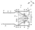
図1ないし図5において、10は風向調整装置である。風向調整装置10は、エアアウトレット、ベンチレータ、レジスタなどとも呼ばれ、空調装置などからの風の吹き出し方向を調整するものである。以下、説明をより明確にするために、風向調整装置10は、風が吹き出す側である風下側を前側、正面側または手前側とし、その反対側、つまり風を受け入れる側である風上側を後側、背後側または奥側として、前側から見て左右方向である両側方向または幅方向、及び、上下方向を規定する。本実施の形態において、風向調整装置10は、自動車などの車両用の空調装置に適用される。風向調整装置10は、任意の位置に配置されていてよいが、図面においては、矢印FR側を前側、矢印RR側を後側、矢印L側を左側、矢印R側を右側、矢印U側を上側、矢印D側を下側とするように配置されているものとする。これらの方向は、あくまで一例として図示されるものであって、風向調整装置10の設置位置や設置向きによって適宜変更されるものとする。
1 to 5, 10 is a wind direction adjustment device. The wind
風向調整装置10は、ケース体12を備える。ケース体12の内部には、流体である空調風が流れる通路部13が形成されている。通路部13内を空調風が所定の第一方向である前後方向に通過する。すなわち、通路部13内において、後側は通気方向の上流側、前側は通気方向の下流側である。また、ケース体12には、通路部13に空調風を受け入れる受入口14が形成されている。受入口14は、通路部13の上流端である後端に位置する。さらに、ケース体12には、通路部13を通過した空調風が吹き出される吹出口15が形成されている。吹出口15は、通路部13の下流端である前端に位置する。
The airflow
本実施の形態において、ケース体12は、角筒状に形成されている。ケース体12は、通路部13の通気方向に所定長を有する。本実施の形態において、ケース体12は、第一方向と交差または直交する第二方向である左右方向に長手状、つまり横長に形成され、第一方向と第二方向とに対して交差または直交する第三方向である上下方向に扁平である。したがって、風向調整装置10は、横型の薄型に形成されている。
In this embodiment, the
図示される例では、ケース体12は、本体部16と、本体部16に取り付けられる枠体であるフィニッシャ17と、を有する。
In the illustrated example, the
本体部16は、後端に受入口14が形成され、前端にフィニッシャ17が取り付けられる取付口20が形成される筒状である。図示される例では、取付口20の縁部に形成されたフランジ部21にフィニッシャ17が取り付けられる。本実施の形態において、本体部16は、上流側をなす上流側本体部22と、下流側をなす下流側本体部23と、が連通部24により連結されて形成されている。下流側本体部23は、上流側本体部22に対して上下方向に拡大されている。そのため、連通部24は、上流側である後側から下流側である前側へと徐々に上下に拡大されるように傾斜して形成されている。
The
フィニッシャ17は、パネルなどとも呼ばれる内装部材である。フィニッシャ17は、風向調整装置10の意匠部分となる意匠部材の機能を有する。本実施の形態において、フィニッシャ17は、四角形枠状の枠体本体であるフィニッシャ本体26を備える。フィニッシャ本体26に吹出口15が開口されている。フィニッシャ本体26には、吹出口15の縁部に、壁部27が形成されている。本実施の形態において、壁部27は、少なくとも吹出口15の上下の縁部において、風の吹出側である前側へと拡開状に傾斜して形成されている。すなわち、吹出口15の上下の縁部は、吹出方向である前側に向かって拡開状に傾斜する拡開面となっている。
The
そして、ケース体12には、調整部30が組み付けられている。調整部30は、ケース体12に対して可動的に設けられ、動作することで通路部13を通過する風の向きを調整、すなわち配風する。
An
図1ないし図4に示すように、調整部30は、配風部として、フィン32と、配風体33と、を有する。また、調整部30は、フィン32及び配風体33を動作させるとともにケース体12に対し固定するリンク部34を有する。さらに、調整部30は、フィン32及び配風体33を操作するための操作部35を有する。
As shown in Figures 1 to 4, the
フィン32は、本実施の形態において、縦ルーバなどとも呼ばれる、上下方向を軸として左右方向に回動することで左右方向に配風する配風部材である。フィン32は、板状に形成されている。フィン32には、リンク部34に回動可能に支持される回動軸32aが上下に突設されている。フィン32は、回動軸32aがリンク部34に回動可能に支持された状態で、厚み方向が左右方向となるように配置される。
In this embodiment, the
また、フィン32は、下流端部である前端部に、操作部35と連結されるリンク軸32bが形成されている。リンク軸32bは、回動軸32aよりも前方の位置で、上下方向に沿って形成されている。
フィン32は、吹出口15に臨んで配置されている。本実施の形態において、フィン32は、吹出口15の上下寸法よりも小さい上下寸法を有する。フィン32は、複数配置されている。フィン32は、左右方向に複数並んで配置されている。本実施の形態において、フィン32は、吹出口15の左右幅全体に亘り配置されている。複数のフィン32が、リンク部34により互いに回動方向が一致するように連動される。
The
配風体33は、本実施の形態において、フラップなどとも呼ばれるものである。配風体33は、上下方向に対をなして配置される。配風体33は、フィン32に対して上下に配置されている。つまり、配風体33は、フィン32とケース体12の上下の側壁部との間に配置されている。配風体33は、吹出口15に対し前後方向に進退することにより上下方向に配風する配風部材である。配風体33,33は、前後方向への進退が互いに反対となるようにリンク部34により連結されている。配風体33は、前後方向において、中立位置で連通部24とフィニッシャ17との間に位置し、その位置から前後に進退するように配置されている。配風体33は、基本的にフィン32よりも上流側つまり後方に位置する。
In this embodiment, the
図4に示すように、配風体33は、左右方向に沿って長手状に延びている。配風体33は、左右方向に並ぶ複数のフィン32よりも両側部が延出する長さに設定されている。配風体33は、風を導く配風面である案内面33aを上流側に面して備える。すなわち、配風体33には、後部に案内面33aが形成されている。案内面33aは、上流側から下流側に向かって通路部13の上下方向の中心側に徐々に接近するように傾斜されている。
As shown in FIG. 4, the
また、配風体33には、リンク部34と連結される支持軸33b,33cが両側部にそれぞれ形成されている。支持軸33b,33cは、前後に離れて配置され、配風体33から側方に突出している。本実施の形態において、前側の支持軸33bは、配風体33の両側から前方に延びる腕部33dに配置されている。
In addition,
そして、リンク部34は、フィン32と配風体33とを連結するリンク37と、配風体33,33を連結する配風体リンク38と、を備えている。
The
リンク37は、スペーサなどともよばれるものである。リンク37は、全体として左右方向に長手状に延びている。
The
リンク37は、フィン32を回動可能に支持するフィン支持部40を有する。フィン支持部40は、フィン32の上下に位置し、上下の回動軸32aをそれぞれ支持孔40aで回動可能に支持する。フィン支持部40は、左右方向に長手状に延びて形成され、すべてのフィン32の回動軸32aに対応して支持孔40aが略等間隔に形成されている。
The
また、リンク37は、フィン支持部40と配風体33とを連結する連結部41を有する。連結部41は、上下のフィン支持部40間を連結してフィン支持部40の両側にそれぞれ形成されている。連結部41は、上下に長手状に形成されている。そのため、リンク37は、四角形枠状つまりフレーム状に形成されている。また、連結部41は、上下の配風体33の前側の支持軸33bを支持孔41aによりそれぞれ回動可能に支持する。支持孔41aは、連結部41の上下両端部に形成されている。すなわち、支持孔41aは、上側のフィン支持部40よりも上方と、下側のフィン支持部40よりも下方と、にそれぞれ形成されている。
The
そして、リンク37には、このリンク37を補強する補強部42が形成されている。本実施の形態において、補強部42は、少なくともいずれかのフィン支持部40、好ましくは上下両方のフィン支持部40に形成され、長手状のフィン支持部40に対して強度剛性を付与している。補強部42は、左右方向に形成されている。図示される例では、補強部42は、左右方向に長手状に形成されている。補強部42は、上下のフィン支持部40に対して交差または直交する方向に突出する。つまり、補強部42は、上側のフィン支持部40から上方に突出し、下側のフィン支持部40から下方に突出する。本実施の形態において、補強部42は、リブ状に形成されている。つまり、補強部42は、前後方向に厚みを有する板状に形成されたフランジ状である。図示される例では、補強部42は、フィン支持部40の後部に連なって形成されている。補強部42は、フィン支持部40において、支持孔40aの後方に位置する。これに限らず、補強部42は、フィン支持部40に一体的に形成された厚肉部などでもよい。補強部42は、好ましくはフィン支持部40の両端間に亘り直線状に連なって形成されている。補強部42の両端部は、連結部41に対してそれぞれ左右方向に離れて位置する。これに限らず、補強部42は、左右方向に間欠的に配置されてもよいし、前後方向に蛇行して形成されていたり、前後方向に湾曲状に形成されていたりしてもよい。
The
また、配風体リンク38は、配風体33,33の後側の支持軸33c,33c間を連結する。配風体リンク38は、リンク37の連結部41と同様に上下に長手状に形成されている。配風体リンク38は、配風体33の両側にそれぞれ配置される。配風体リンク38は、配風体33の後側の支持軸33cを支持孔38aによりそれぞれ回動可能に支持する。上下の配風体33,33と、リンク37の連結部41と、配風体リンク38とによって、平行リンク機構が構成されている。そのため、上下の配風体33,33は、支持軸33b,33cを結ぶ線同士が互いに平行を保ちながら前後に進退するように構成されている。
The air
リンク37の連結部41と配風体リンク38とは、被支持体43によって互いに連結されている。被支持体43は、連結部41と配風体リンク38との上下方向の中央部を互いに連結している。被支持体43は、連結部41及び配風体リンク38と交差する方向である前後に長手状に形成されている。被支持体43は、支持軸43a,43aを備え、前側の支持軸43aが連結部41の支持孔41bに回動可能に支持され、後側の支持軸43aが配風体リンク38の支持孔38bに回動可能に支持される。被支持体43は、両側の連結部41及び配風体リンク38毎に配置されている。すなわち、被支持体43は、リンク部34の両側に位置する。被支持体43は、上下の配風体33,33と、リンク37の連結部41と、配風体リンク38とからなる平行リンク機構の中央部を通る部材である。被支持体43は、リンク部34の動作時に上下の配風体33,33の支持軸33b,33cを結ぶ線と平行を保つ。
The connecting
被支持体43は、リンク部34をケース体12に固定する機能を有する。本実施の形態において、被支持体43は、ケース体12の左右の側壁部に形成された支持受け部45に嵌合される。支持受け部45は、ケース体12の本体部16の取付口20から前後方向に沿って溝状に形成されている。支持受け部45に嵌合された被支持体43は、ケース体12のフィニッシャ17に形成された押さえ部46によって前方から抜け止めされる。押さえ部46は、フィニッシャ本体26の背面側にて吹出口15の両側から後方に突設され、本体部16にフィニッシャ17を取り付けた状態で支持受け部45に前方から挿入されて支持受け部45の取付口20側の開口を閉塞するようになっている。
The supported
操作部35は、フィン32の前部に取り付けられる。操作部35は、左右方向に長手状に形成され、複数のフィン32に亘り一体的に取り付けられる。操作部35には、フィン32のリンク軸32bを回動可能に支持する支持孔35aが後部に形成されている。支持孔35aは、操作部35の後部に形成され、後方に開口されている。本実施の形態において、操作部35の両側には、両側に位置するフィン32のリンク軸32bを回動可能に支持する支持孔35bがそれぞれ形成されている。これら支持孔35bは、支持孔35aとは異なり、操作部35の両側に切り欠き形成されて、両側に位置するフィン32のリンク軸32bを支持孔35aとは異なる方向から挿入される。
The operating
次に、第1の実施の形態の作用を説明する。 Next, we will explain the operation of the first embodiment.
風向調整装置10を組み立てる際には、まず、フィン32を操作部35に組み付ける。このとき、複数のフィン32のうち、両側のフィン32を除くフィン32については、操作部35の支持孔35aにリンク軸32bをそれぞれ後方から挿入し、両側のフィン32については、操作部35の両側の支持孔35bにリンク軸32bを側方から挿入することで、両側のフィン32とそれ以外のフィン32との操作部35への挿入方向を変えてフィン32に対し操作部35を抜けにくくする。
When assembling the airflow
次いで、操作部35に組み付けた各フィン32を、リンク37に組み付ける。各フィン32の上下の回動軸32aを、リンク37の上下のフィン支持部40の支持孔40aに挿入して回動可能に支持する。
Next, each
さらに、リンク37の連結部41の上下の支持孔41aに対し、上下の配風体33の前側の支持軸33bを挿入して回動可能に支持するとともに、配風体リンク38の上下の支持孔38aに対し、上下の配風体33の後側の支持軸33cを挿入して回動可能に支持する。
Furthermore, the
この状態で、連結部41の支持孔41bに被支持体43の前側の支持軸43aを挿入して回動可能に支持するとともに、配風体リンク38の支持孔38bに被支持体43の後側の支持軸43aを挿入して回動可能に支持する。この結果、リンク部34により、フィン32及び配風体33が一体的に連結されて調整部30が構成される。
In this state, the
そして、調整部30を取付口20から本体部16の内部に挿入し、被支持体43を支持受け部45に嵌合させる。この後、本体部16に対してフィニッシャ17を前方から取り付けて押さえ部46を支持受け部45に前方から挿入しつつ、フィニッシャ17を本体部16のフランジ部21に固定して、風向調整装置10が完成する。
Then, the
風向調整装置10は、受入口14を空調装置と連結して配置する。空調装置からの空調風は、通路部13を通過し、調整部30によって配風されて吹出口15から吹き出される。調整部30では、フィン32により左右方向に配風し、配風体33により上下方向に配風する。
The airflow
図1に示す中立位置では、フィン32が吹出口15に対し正対し、上下の配風体33,33が前後方向に略等しい位置となる。すなわち、配風体33,33は、上下に略対称な位置に案内面33a,33aが位置する。そのため、通路部13を通過する風が上下の配風体33,33の案内面33a,33aに同時に当たり、案内面33a,33aにより絞られた風がフィン32に沿って吹出口15から吹き出される。したがって、風向の変化が生じることがなく、風が吹出口15からフィン32に沿って正面方向に吹き出される。
In the neutral position shown in FIG. 1, the
また、図1に示す中立位置から、図2に示すように、操作部35を上方に回動させると、リンク37が被支持体43の支持軸43aを中心として回動し、リンク37、配風体リンク38および配風体33,33からなる平行リンク機構により、上側の配風体33が吹出口15から退避するように上流側である後方へ移動し、下側の配風体33が吹出口15側に接近するように下流側である前方へ移動する。上側の配風体33は、最大に回動させた位置で案内面33aの上流側が上流側本体部22の上面と略面一となる位置で連通部24の近傍に位置する。また、下側の配風体33は、最大に回動させた位置で案内面33aの下流側が吹出口15の下側の縁部よりも上方に位置する。そのため、配風体33,33が通路部13の通気方向である前後方向にずれる。さらに、フィン32は、上部が上側の配風体33の案内面33aに対して前方下側に離れ、下部が下側の配風体33の案内面33aに近接する。これにより、通路部13を通過する風が上流側に位置する上側の配風体33の案内面33aに先に当たり、この案内面33aに沿って下方に導かれた風がその延長上の下流側下方に位置する下側の配風体33の案内面33aに沿って上方へと導かれることで、フィン32に沿って吹出口15から上方に吹き出される。
When the operating
このとき、リンク37の上側の補強部42が上側の配風体33の案内面33aに近接するとともに、案内面33aに沿って位置することで、この配風体33の案内面33aの背後側である配風体33の前方の空間へと風が入り込むことを防止するとともに、案内面33aに沿って案内された風を乱すことなくフィン32へと導く。また、リンク37の下側の補強部42は、下側の配風体33の案内面33aの延長面よりも下方に位置し、下側の配風体33の案内面33aによる風の案内を妨げない。
At this time, the upper reinforcing
同様に、図1に示す中立位置から、図3に示すように、操作部35を下方に回動させると、リンク37が被支持体43の支持軸43aを中心として回動し、リンク37、配風体リンク38および配風体33,33からなる平行リンク機構により、上側の配風体33が吹出口15に接近するように下流側である前方へ移動し、下側の配風体33が吹出口15側から退避するように上流側である後方へ移動する。上側の配風体33は、最大に回動させた位置で案内面33aの下流側が吹出口15の上側の縁部よりも下方に位置する。また、下側の配風体33は、最大に回動させた位置で案内面33aの上流側が上流側本体部22の下面と略面一となる位置で連通部24の近傍に位置する。そのため、配風体33,33が通路部13の通気方向である前後方向にずれる。さらに、フィン32は、下部が下側の配風体33の案内面33aに対して前方上側に離れ、上部が上側の配風体33の案内面33aに近接する。これにより、通路部13を通過する風が上流側に位置する下側の配風体33の案内面33aに先に当たり、この案内面33aに沿って上方に導かれた風がその延長上の下流側上方に位置する上側の配風体33の案内面33aに沿って下方へと導かれて、フィン32に沿って吹出口15から下方に吹き出される。
Similarly, when the operating
このとき、リンク37の下側の補強部42が下側の配風体33の案内面33aに近接するとともに、案内面33aに沿って位置することで、この配風体33の案内面33aの背後側である配風体33の前方の空間へと風が入り込むことを防止するとともに、案内面33aに沿って案内された風を乱すことなくフィン32へと導く。また、リンク37の上側の補強部42は、上側の配風体33の案内面33aの延長面よりも上方に位置し、上側の配風体33の案内面33aによる風の案内を妨げない。
At this time, the lower reinforcing
また、操作部35を左右方向に操作すると、操作部35に対してリンク軸32bにより連結された各フィン32が回動軸32aを中心として操作部35の操作方向と同方向に左右回動し、左右に配風する。
When the operating
したがって、配風体33,33の進退による上下方向の配風と、フィン32の回動による左右方向の配風との組み合わせにより、風向調整装置10は、任意方向に風向を調整可能となる。
Therefore, by combining vertical air distribution by the advancement and retreat of the
このように、本実施の形態によれば、左右方向に延びるリンク37を通路部13内で左右方向を軸として回動可能とし、このリンク37に対し、配風体33を上下方向に対をなして配置し左右方向を軸として回動可能に通路部13内に配置して、リンク37の回動に応じて配風体33が吹出口15に対し前後方向に進退するように構成するとともに、リンク37に対し、フィン32を、上下方向を軸として回動可能に配置し、かつ、リンク37に左右方向に補強部42を形成することで、風などによるリンク37の撓みを補強部42によって抑制でき、リンク37によってフィン32及び配風体33を安定的に動作させて、フィン32によって左右方向の配風性能を向上し、配風体33によって通路部13内で風が通る経路を最小限の構成で形成して風を上下方向に曲げやすくかつ通気抵抗を抑制して、簡素な構成で配風性能を安定させることができる。また、構成が簡素であるため、安価に製造できる。
In this way, according to this embodiment, the
さらに、配風体33は、通気抵抗が小さいため、風の通過による騒音が発生しにくい。
In addition, the
フィン32と配風体33とを連結するリンク37を、フィン32を回動可能に支持する左右方向に長手状のフィン支持部40と、フィン支持部40と配風体33とを連結する連結部41とで構成し、フィン支持部40に補強部42を形成することで、連結部41と比較して長手状のフィン支持部40を補強部42によって確実に補強し、風などによるリンク37の撓みを抑制して、安定した配風性能を確保できる。
The
リンク37が最大に回動した位置で補強部42が配風体33の案内面33aに沿って位置するため、配風体33の案内面33aに沿って案内された風を妨げることなくさらに補強部42によって案内することが可能となり、風向指向性をより向上できる。特に、補強部42が左右方向に直線状に連なってフィン支持部40の両端間に亘り形成されているので、補強部42により風をより効果的に案内することが可能となる。
When the
また、リンク37が最大に回動した位置で補強部42が配風体33に近接して位置するため、配風体33の案内面33aに沿って案内された風が配風体33の案内面33aの背後側に回り込みにくくなり、風向指向性をより向上できる。
In addition, since the reinforcing
操作部35を、左右方向に延びる板状に形成することで、吹出口15から吹き出される風を操作部35により妨げにくく、操作部35による配風性能の低下を抑制できるとともに、例えば中立位置において、操作部35によって風を上下に分散させにくく、吹出口15から前方へと集中風を吹き出すことが可能となる。
By forming the operating
なお、図6に示す第2の実施の形態のように、配風体リンク38とリンク37の連結部41とを、配風体33と連結される長手方向の両端部に対して、通路部13側つまりケース体12に支持される長手方向の中央部が吹出口15側に位置するように屈曲状に形成してもよい。この構成では、配風体33の取り付け位置を変更することなくリンク37の回動位置を吹出口15側である前側にオフセットできるため、多様な前後寸法の風向調整装置に設定可能となるとともに、フィニッシャ17を曲線状とするなどの形状変更にも容易に対応可能となる。
As in the second embodiment shown in Figure 6, the
また、各実施の形態において、操作部35は、手動により操作されるものに限らず、モータなどのアクチュエータにより操作されるものでもよい。このように電動で動作させる場合には、操作部35を小型化可能となる。
In addition, in each embodiment, the
本発明は、例えば自動車の空調用の風向調整装置として好適に用いることができる。 The present invention can be suitably used, for example, as a wind direction adjustment device for automotive air conditioning.
10 風向調整装置
13 通路部
15 吹出口
32 フィン
33 配風体
33a 配風面である案内面
37 リンク
38 配風体リンク
40 フィン支持部
41 連結部
42 補強部
10 Wind direction adjustment device
13 Passage
15 Air outlet
32 Finn
33 Wind distribution body
33a Guide surface which is the wind distribution surface
37 Links
38 Wind-distributing body links
40 Fin support
41 Connection
42 Reinforcement
Claims (5)
この通路部内で前記第一方向に対して交差する第二方向を軸として回動可能で、前記第二方向に延びるリンクと、
前記通路部内で前記第一方向と前記第二方向とに対して交差する第三方向の一方と他方とに対をなして配置された配風体と、
前記通路部内で前記第三方向を軸として前記リンクに回動可能に配置されたフィンと、
前記リンクに対して前記第一方向の上流側に位置し、一方の前記配風体と他方の前記配風体とを連結する配風体リンクと、を備え、
前記リンクは、
前記第二方向に延びて前記フィンを回動可能に支持するフィン支持部と、
前記フィン支持部と各前記配風体とを連結する連結部と、
前記第二方向に形成された補強部と、を有し、
前記配風体は、それぞれ前記第一方向から流れる流体を案内する配風面を有し、前記配風面が前記第一方向の上流側から下流側に向かって前記通路部の前記第三方向の中心側に接近するように傾斜し、
前記連結部及び前記配風体リンクがそれぞれ各前記配風体に回動可能に接続されて、前記リンク及び前記配風体リンクの回動に連動して一方の前記配風体と他方の前記配風体とを互いに平行かつ前記第一方向に沿う状態を保ちつつ前記吹出口に対し前記第一方向にそれぞれ反対に進退させる平行リンク機構が構成されている
ことを特徴とする風向調整装置。 a passage portion having an air outlet and through which a fluid flows in a predetermined first direction toward the air outlet;
a link that is rotatable about an axis in a second direction intersecting the first direction within the passage and extends in the second direction;
A pair of air distribution bodies are arranged in the passage portion on one side and the other side of a third direction intersecting the first direction and the second direction;
a fin disposed on the link within the passage so as to be rotatable about an axis in the third direction;
a wind distribution body link located upstream of the link in the first direction and connecting one of the wind distribution bodies to the other of the wind distribution bodies;
The link is:
A fin support portion extending in the second direction and rotatably supporting the fin;
A connecting portion that connects the fin support portion and each of the air distribution bodies;
A reinforcing portion formed in the second direction,
Each of the air distribution bodies has an air distribution surface that guides the fluid flowing from the first direction, and the air distribution surface is inclined from the upstream side to the downstream side in the first direction so as to approach the center side of the passage portion in the third direction,
The connecting portion and the air distribution body link are rotatably connected to each of the air distribution bodies, and a parallel link mechanism is configured in which one of the air distribution bodies and the other of the air distribution bodies are moved forward and backward in opposite directions in the first direction relative to the air outlet in conjunction with the rotation of the link and the air distribution body link while maintaining a state in which they are parallel to each other and aligned along the first direction.
A wind direction adjustment device characterized by the above.
ことを特徴とする請求項1記載の風向調整装置。 The airflow direction adjusting device according to claim 1 , wherein the reinforcing portion is formed on the fin support portion.
ことを特徴とする請求項1または2記載の風向調整装置。 The airflow direction adjustment device according to claim 1 or 2, characterized in that the connecting portion is formed in a longitudinal shape and is bent so that the longitudinal center portion supported on the passage portion side is positioned on the air outlet side relative to both end portions connected to the air distribution body.
ことを特徴とする請求項1ないし3いずれか一記載の風向調整装置。 4. The airflow direction adjusting device according to claim 1, wherein the reinforcing portion is located along the air distribution surface of the air distribution body when the link is rotated to the maximum extent.
ことを特徴とする請求項1ないし4いずれか一記載の風向調整装置。 5. The airflow direction adjusting device according to claim 1, wherein the reinforcing portion is located adjacent to the air distribution body when the link is rotated to the maximum extent.
Priority Applications (1)
| Application Number | Priority Date | Filing Date | Title |
|---|---|---|---|
| JP2021055474A JP7586751B2 (en) | 2021-03-29 | 2021-03-29 | Wind direction adjustment device |
Applications Claiming Priority (1)
| Application Number | Priority Date | Filing Date | Title |
|---|---|---|---|
| JP2021055474A JP7586751B2 (en) | 2021-03-29 | 2021-03-29 | Wind direction adjustment device |
Publications (2)
| Publication Number | Publication Date |
|---|---|
| JP2022152633A JP2022152633A (en) | 2022-10-12 |
| JP7586751B2 true JP7586751B2 (en) | 2024-11-19 |
Family
ID=83555845
Family Applications (1)
| Application Number | Title | Priority Date | Filing Date |
|---|---|---|---|
| JP2021055474A Active JP7586751B2 (en) | 2021-03-29 | 2021-03-29 | Wind direction adjustment device |
Country Status (1)
| Country | Link |
|---|---|
| JP (1) | JP7586751B2 (en) |
Citations (3)
| Publication number | Priority date | Publication date | Assignee | Title |
|---|---|---|---|---|
| JP2014020629A (en) | 2012-07-13 | 2014-02-03 | Nippon Plast Co Ltd | Wind direction adjusting device |
| WO2018074022A1 (en) | 2016-10-17 | 2018-04-26 | 本田技研工業株式会社 | Blowout device for air conditioner |
| WO2019207659A1 (en) | 2018-04-24 | 2019-10-31 | 三菱電機株式会社 | Wind direction adjustment mechanism, indoor unit of air conditioner, and air conditioner |
-
2021
- 2021-03-29 JP JP2021055474A patent/JP7586751B2/en active Active
Patent Citations (3)
| Publication number | Priority date | Publication date | Assignee | Title |
|---|---|---|---|---|
| JP2014020629A (en) | 2012-07-13 | 2014-02-03 | Nippon Plast Co Ltd | Wind direction adjusting device |
| WO2018074022A1 (en) | 2016-10-17 | 2018-04-26 | 本田技研工業株式会社 | Blowout device for air conditioner |
| WO2019207659A1 (en) | 2018-04-24 | 2019-10-31 | 三菱電機株式会社 | Wind direction adjustment mechanism, indoor unit of air conditioner, and air conditioner |
Also Published As
| Publication number | Publication date |
|---|---|
| JP2022152633A (en) | 2022-10-12 |
Similar Documents
| Publication | Publication Date | Title |
|---|---|---|
| CN101500830B (en) | air conditioner | |
| CN100475584C (en) | Components for automotive interior air conditioning units and automotive interior air conditioning units | |
| JP7013149B2 (en) | register | |
| JP5614878B2 (en) | Wind direction adjustment device | |
| JP7586719B2 (en) | Wind direction adjustment device | |
| JP7394541B2 (en) | Wind direction adjustment device | |
| JP5916075B2 (en) | Wind direction adjustment device | |
| JP7586751B2 (en) | Wind direction adjustment device | |
| JP7693272B2 (en) | Wind direction adjustment device | |
| WO2015115058A1 (en) | Air conditioning device for vehicle | |
| JP3333923B2 (en) | Ventilator air conditioning structure | |
| WO2012120980A1 (en) | Air-blowing device | |
| JP6054191B2 (en) | Door structure for air conditioning unit and air conditioning unit | |
| JP2025043601A (en) | Wind direction adjustment device | |
| JP7680313B2 (en) | Wind direction adjustment device | |
| JP4967670B2 (en) | Ventilation grill for vehicles | |
| JP7261578B2 (en) | Wind direction adjustment device and air conditioner | |
| JP2024129364A (en) | Wind direction adjustment device | |
| JP7601581B2 (en) | Wind direction adjustment device | |
| JP7487036B2 (en) | Wind direction adjustment device | |
| JP2024136477A (en) | Wind direction adjustment device | |
| JP7765258B2 (en) | Wind direction adjustment device | |
| JP2025012824A (en) | Wind direction adjustment device | |
| JP6599216B2 (en) | Wind direction adjustment device | |
| JP7754697B2 (en) | Wind direction adjustment device |
Legal Events
| Date | Code | Title | Description |
|---|---|---|---|
| A621 | Written request for application examination |
Free format text: JAPANESE INTERMEDIATE CODE: A621 Effective date: 20231214 |
|
| RD04 | Notification of resignation of power of attorney |
Free format text: JAPANESE INTERMEDIATE CODE: A7424 Effective date: 20240311 |
|
| A977 | Report on retrieval |
Free format text: JAPANESE INTERMEDIATE CODE: A971007 Effective date: 20240725 |
|
| A131 | Notification of reasons for refusal |
Free format text: JAPANESE INTERMEDIATE CODE: A131 Effective date: 20240731 |
|
| A521 | Request for written amendment filed |
Free format text: JAPANESE INTERMEDIATE CODE: A523 Effective date: 20240906 |
|
| TRDD | Decision of grant or rejection written | ||
| A01 | Written decision to grant a patent or to grant a registration (utility model) |
Free format text: JAPANESE INTERMEDIATE CODE: A01 Effective date: 20241106 |
|
| A61 | First payment of annual fees (during grant procedure) |
Free format text: JAPANESE INTERMEDIATE CODE: A61 Effective date: 20241107 |
|
| R150 | Certificate of patent or registration of utility model |
Ref document number: 7586751 Country of ref document: JP Free format text: JAPANESE INTERMEDIATE CODE: R150 |