JP7585366B2 - Method for manufacturing intermediate products for battery cells, intermediate products for battery cells, and ultrasonic device for manufacturing the intermediate products - Google Patents
Method for manufacturing intermediate products for battery cells, intermediate products for battery cells, and ultrasonic device for manufacturing the intermediate products Download PDFInfo
- Publication number
- JP7585366B2 JP7585366B2 JP2023019994A JP2023019994A JP7585366B2 JP 7585366 B2 JP7585366 B2 JP 7585366B2 JP 2023019994 A JP2023019994 A JP 2023019994A JP 2023019994 A JP2023019994 A JP 2023019994A JP 7585366 B2 JP7585366 B2 JP 7585366B2
- Authority
- JP
- Japan
- Prior art keywords
- battery cell
- cell body
- wound battery
- horn
- manufacturing
- Prior art date
- Legal status (The legal status is an assumption and is not a legal conclusion. Google has not performed a legal analysis and makes no representation as to the accuracy of the status listed.)
- Active
Links
Images


Classifications
-
- B—PERFORMING OPERATIONS; TRANSPORTING
- B23—MACHINE TOOLS; METAL-WORKING NOT OTHERWISE PROVIDED FOR
- B23K—SOLDERING OR UNSOLDERING; WELDING; CLADDING OR PLATING BY SOLDERING OR WELDING; CUTTING BY APPLYING HEAT LOCALLY, e.g. FLAME CUTTING; WORKING BY LASER BEAM
- B23K20/00—Non-electric welding by applying impact or other pressure, with or without the application of heat, e.g. cladding or plating
- B23K20/10—Non-electric welding by applying impact or other pressure, with or without the application of heat, e.g. cladding or plating making use of vibrations, e.g. ultrasonic welding
- B23K20/106—Features related to sonotrodes
-
- H—ELECTRICITY
- H01—ELECTRIC ELEMENTS
- H01M—PROCESSES OR MEANS, e.g. BATTERIES, FOR THE DIRECT CONVERSION OF CHEMICAL ENERGY INTO ELECTRICAL ENERGY
- H01M10/00—Secondary cells; Manufacture thereof
- H01M10/04—Construction or manufacture in general
- H01M10/0404—Machines for assembling batteries
- H01M10/0409—Machines for assembling batteries for cells with wound electrodes
-
- H—ELECTRICITY
- H01—ELECTRIC ELEMENTS
- H01M—PROCESSES OR MEANS, e.g. BATTERIES, FOR THE DIRECT CONVERSION OF CHEMICAL ENERGY INTO ELECTRICAL ENERGY
- H01M10/00—Secondary cells; Manufacture thereof
- H01M10/04—Construction or manufacture in general
- H01M10/0422—Cells or battery with cylindrical casing
-
- H—ELECTRICITY
- H01—ELECTRIC ELEMENTS
- H01M—PROCESSES OR MEANS, e.g. BATTERIES, FOR THE DIRECT CONVERSION OF CHEMICAL ENERGY INTO ELECTRICAL ENERGY
- H01M10/00—Secondary cells; Manufacture thereof
- H01M10/04—Construction or manufacture in general
- H01M10/0431—Cells with wound or folded electrodes
-
- H—ELECTRICITY
- H01—ELECTRIC ELEMENTS
- H01M—PROCESSES OR MEANS, e.g. BATTERIES, FOR THE DIRECT CONVERSION OF CHEMICAL ENERGY INTO ELECTRICAL ENERGY
- H01M10/00—Secondary cells; Manufacture thereof
- H01M10/05—Accumulators with non-aqueous electrolyte
- H01M10/058—Construction or manufacture
- H01M10/0587—Construction or manufacture of accumulators having only wound construction elements, i.e. wound positive electrodes, wound negative electrodes and wound separators
-
- H—ELECTRICITY
- H01—ELECTRIC ELEMENTS
- H01M—PROCESSES OR MEANS, e.g. BATTERIES, FOR THE DIRECT CONVERSION OF CHEMICAL ENERGY INTO ELECTRICAL ENERGY
- H01M50/00—Constructional details or processes of manufacture of the non-active parts of electrochemical cells other than fuel cells, e.g. hybrid cells
- H01M50/50—Current conducting connections for cells or batteries
- H01M50/531—Electrode connections inside a battery casing
- H01M50/533—Electrode connections inside a battery casing characterised by the shape of the leads or tabs
-
- B—PERFORMING OPERATIONS; TRANSPORTING
- B23—MACHINE TOOLS; METAL-WORKING NOT OTHERWISE PROVIDED FOR
- B23K—SOLDERING OR UNSOLDERING; WELDING; CLADDING OR PLATING BY SOLDERING OR WELDING; CUTTING BY APPLYING HEAT LOCALLY, e.g. FLAME CUTTING; WORKING BY LASER BEAM
- B23K2101/00—Articles made by soldering, welding or cutting
- B23K2101/36—Electric or electronic devices
-
- Y—GENERAL TAGGING OF NEW TECHNOLOGICAL DEVELOPMENTS; GENERAL TAGGING OF CROSS-SECTIONAL TECHNOLOGIES SPANNING OVER SEVERAL SECTIONS OF THE IPC; TECHNICAL SUBJECTS COVERED BY FORMER USPC CROSS-REFERENCE ART COLLECTIONS [XRACs] AND DIGESTS
- Y02—TECHNOLOGIES OR APPLICATIONS FOR MITIGATION OR ADAPTATION AGAINST CLIMATE CHANGE
- Y02E—REDUCTION OF GREENHOUSE GAS [GHG] EMISSIONS, RELATED TO ENERGY GENERATION, TRANSMISSION OR DISTRIBUTION
- Y02E60/00—Enabling technologies; Technologies with a potential or indirect contribution to GHG emissions mitigation
- Y02E60/10—Energy storage using batteries
-
- Y—GENERAL TAGGING OF NEW TECHNOLOGICAL DEVELOPMENTS; GENERAL TAGGING OF CROSS-SECTIONAL TECHNOLOGIES SPANNING OVER SEVERAL SECTIONS OF THE IPC; TECHNICAL SUBJECTS COVERED BY FORMER USPC CROSS-REFERENCE ART COLLECTIONS [XRACs] AND DIGESTS
- Y02—TECHNOLOGIES OR APPLICATIONS FOR MITIGATION OR ADAPTATION AGAINST CLIMATE CHANGE
- Y02P—CLIMATE CHANGE MITIGATION TECHNOLOGIES IN THE PRODUCTION OR PROCESSING OF GOODS
- Y02P70/00—Climate change mitigation technologies in the production process for final industrial or consumer products
- Y02P70/50—Manufacturing or production processes characterised by the final manufactured product
Landscapes
- Engineering & Computer Science (AREA)
- Chemical & Material Sciences (AREA)
- Chemical Kinetics & Catalysis (AREA)
- Electrochemistry (AREA)
- General Chemical & Material Sciences (AREA)
- Manufacturing & Machinery (AREA)
- Mechanical Engineering (AREA)
- Secondary Cells (AREA)
- Connection Of Batteries Or Terminals (AREA)
- Manufacturing Of Electrical Connectors (AREA)
Description
本発明は、電池セル用中間製品の製造方法、電池セル用中間製品、及び当該中間製品の製造のための超音波デバイスに関する。 The present invention relates to a method for manufacturing intermediate products for battery cells, intermediate products for battery cells, and ultrasonic devices for manufacturing the intermediate products.
電気自動車及び同様の用途では、いくつかの種類の電池が使用されており、これらの電池に関するいくつかの改良が過去からなされてきている。 Several types of batteries are used in electric vehicles and similar applications, and several improvements have been made to these batteries over the years.
現在、一部の電池は、螺旋状の設計を有する電池セルを使用する。そのような設計では、カソード、アノード、及び少なくとも1つのセパレータを有する層は、中心長手方向軸周りに巻かれる。多くの場合、この層のアノード及びカソードは、金属箔によって形成される。言い換えれば、これらの電池は、ペーストを有する巻き上げられた金属箔からなる。 Currently, some batteries use battery cells with a spiral design. In such a design, a layer with a cathode, an anode, and at least one separator is wound around a central longitudinal axis. In many cases, the anode and cathode of this layer are formed by metal foil. In other words, these batteries consist of a rolled up metal foil with a paste.
カソード及びアノードは、巻かれた又は巻き回された電池セル本体を電池セル本体のハウジングに電気的に接続するためのタブを有する。したがって、結果として得られたコイルの端部にはタブがある。 The cathode and anode have tabs to electrically connect the wound or coiled battery cell body to the battery cell body housing. Thus, the resulting coil has tabs at the ends.
電池を充電又は放電するために、電流は、タブを介してコイル全体又は巻線を通過しなければならない。これは、電流がカソード又はアノードに沿ってタブまでずっと移動して、セルから出なければならず、結果として生じる熱を放散しなければならないとき、オーム抵抗が距離と共に増加するので、電池セルの寸法を制限する。 To charge or discharge the battery, current must pass through the entire coil or winding, via the tabs. This limits the size of the battery cell because ohmic resistance increases with distance as the current must travel all the way along the cathode or anode to the tabs and exit the cell, dissipating the resulting heat.
このような電池セルの寸法を大きくする手法は、このコイル内に交差接続を確立することであり、タブの必要性を排除する。これにより、電気の経路が極めて短くなり、電流の経路が短くなるため抵抗が小さくなり、これは熱の発生を小さくすることを意味する。このような電池セルの例は、US 2020/0144676 A1(米国特許出願公開第2020/0144676号明細書)に記載されている。 A way to increase the size of such a battery cell is to establish cross connections within the coil, eliminating the need for tabs. This allows for a very short electrical path, which means less resistance due to a shorter path for current, which means less heat generation. An example of such a battery cell is described in US 2020/0144676 A1.
US 2020/0144676 A1(米国特許出願公開第2020/0144676号明細書)によれば、セルは、その上に配置された第1のコーティングを有する第1の基板を含み、第1の基板の幅に沿った近位端にある第1の基板の第2の部分は、導電性材料を備える。内側セパレータは、第1の基板の上に配置される。第2の基板は、内側セパレータの上に配置される。第2の基板は、その上に配置された第2のコーティングを有する。第1の基板、内側セパレータ、及び第2の基板は、連続的になっており、第1の基板、内側セパレータ、及び第2の基板は、中心軸周りに巻かれる。 According to US 2020/0144676 A1, a cell includes a first substrate having a first coating disposed thereon, and a second portion of the first substrate at a proximal end along the width of the first substrate comprises a conductive material. An inner separator is disposed on the first substrate. A second substrate is disposed on the inner separator. The second substrate has a second coating disposed thereon. The first substrate, the inner separator, and the second substrate are continuous, and the first substrate, the inner separator, and the second substrate are wound around a central axis.
本発明は、上記従来技術に鑑み、電池セルの中間製品の代替製造方法、電池セル用中間製品、及び電池セル用中間製品の製造のための超音波デバイスを提供することを目的とする。 In view of the above-mentioned conventional techniques, the present invention aims to provide an alternative manufacturing method for intermediate products of battery cells, an intermediate product for battery cells, and an ultrasonic device for manufacturing intermediate products for battery cells.
上記課題は、請求項1に記載の電池セル用中間製品の製造方法、請求項12に記載の電池セル用中間製品、及び請求項13に記載の電池セル用中間製品の製造のための超音波デバイスによって解決される。更なる好ましい実施形態及び開発は、以下の説明、図面及び添付の特許請求の範囲から生じる。
The above problem is solved by a method for manufacturing an intermediate product for a battery cell according to
超音波による電池セル用中間製品の本発明の製造方法は、第1の電極、セパレータ、及び第2の電極の層が複数の巻線で中心長手方向軸周りに巻き回される巻回電池セル本体を提供するステップであって、第1の電極及び第2の電極の少なくとも一方が、長手方向の一方の前端に延在する導電性部分を備え、導電性部分が、好ましくは金属箔を備えるか、又は金属箔からなる、ステップと、巻回電池セル本体を初期位置で超音波デバイス内に配置するステップであって、これにより、導電性部分を有する巻回電池セル本体の前端が、超音波デバイスのホーンの前端加工面に対向する、ステップと、巻回電池セル本体及びホーンを、初期位置から、ホーンの前端加工面が巻回電池セル本体の前端に当接する加工位置まで互いに対して移動させるステップと、続いて、巻回電池セル本体の前端の導電性部分に少なくとも部分的に超音波を印加することによって、巻回電池セル本体を加工するステップであって、これにより、導電性部分が、ホーンによって、巻回電池セル本体の前端で少なくとも部分的に変形され、好ましくは曲げられ、加工された巻回電池セル本体が結果として得られる、ステップと、その後、加工された巻回電池セル本体及びホーンを加工位置から取り外し位置に互いに対して移動させるステップと、加工された巻回電池セル本体を超音波デバイスから取り外すステップと、を含む。 The inventive method for ultrasonically manufacturing an intermediate product for a battery cell includes the steps of providing a wound battery cell body having a layer of a first electrode, a separator, and a second electrode wound about a central longitudinal axis with a plurality of windings, at least one of the first electrode and the second electrode having a conductive portion extending to one longitudinal front end, the conductive portion preferably comprising or consisting of a metal foil; placing the wound battery cell body in an initial position within an ultrasonic device, whereby a front end of the wound battery cell body having the conductive portion faces a front end processing surface of a horn of the ultrasonic device; and moving the wound battery cell body and the horn from the initial position to the horn. the horn and the horn relative to one another to a processing position where a front end processing surface of the horn abuts the front end of the wound battery cell body, followed by processing the wound battery cell body by at least partially applying ultrasonic waves to a conductive portion of the front end of the wound battery cell body, whereby the conductive portion is at least partially deformed, preferably bent, at the front end of the wound battery cell body by the horn, resulting in a processed wound battery cell body, thereafter moving the processed wound battery cell body and the horn relative to one another from the processing position to a removal position, and removing the processed wound battery cell body from the ultrasonic device.
本発明の製造方法の出発点は、一般に知られているように、巻き回された、又は巻かれた電池セル本体である。上述したように、そのような巻回電池セル本体は、中心長手方向軸周りに巻き上げられる、第1の電極、例えばカソード、セパレータ、及び第2の電極、例えばアノードの層からなる。したがって、第1の電極は、セパレータの第1の側に配置され、第2の電極は、セパレータの第1の側とは反対の第2の側に配置される。場合によっては、更なるセパレータが存在してもよい。言い換えれば、巻回電池セル本体は、その上にペーストを有する巻き上げられた金属箔によって形成されてもよい。巻回電池セル本体の層は、上方から見て、すなわち、中心長手方向軸に沿って見て、渦巻状の形状を有する。したがって、層と中心長手方向軸との間の径方向距離は連続的に変化する。 The starting point of the manufacturing method of the present invention is a wound or rolled battery cell body, as is generally known. As mentioned above, such a wound battery cell body consists of a layer of a first electrode, e.g. a cathode, a separator, and a second electrode, e.g. an anode, wound around a central longitudinal axis. Thus, the first electrode is arranged on a first side of the separator, and the second electrode is arranged on a second side opposite to the first side of the separator. Optionally, a further separator may be present. In other words, the wound battery cell body may be formed by a rolled-up metal foil having a paste thereon. The layer of the wound battery cell body has a spiral shape when viewed from above, i.e. along the central longitudinal axis. Thus, the radial distance between the layer and the central longitudinal axis varies continuously.
第1の電極、すなわちカソード、及び第2の電極、すなわちアノードのうちの少なくとも1つは、導電性部分を備える。好ましくは、導電性部分は、金属箔を備えるか、又は金属箔からなる。導電性部分は、まず、電池セル本体の長手方向の前端に延在する。第1の電極が、第1の導電性部分を有すると仮定すると、それぞれの第1の導電性部分は、巻回電池セル本体の第1の前端から延在することになる。したがって、第2の電極も導電性部分を有する場合、すなわち第2の導電性部分が存在する場合、この第2の導電性部分は、第1の前端とは反対側の巻回電池セル本体の第2の前端から延在することになる。 At least one of the first electrode, i.e. the cathode, and the second electrode, i.e. the anode, comprises a conductive portion. Preferably, the conductive portion comprises or consists of a metal foil. The conductive portion first extends to the longitudinal front end of the battery cell body. Assuming that the first electrodes have a first conductive portion, the respective first conductive portion will extend from the first front end of the wound battery cell body. Thus, if the second electrode also has a conductive portion, i.e. if a second conductive portion is present, this second conductive portion will extend from the second front end of the wound battery cell body opposite the first front end.
このような巻回電池セル本体は、第1のステップで提供された後、第2のステップで初期位置で超音波デバイス内に配置される。この目的のために、電池セル本体は、好ましくは、例えば、クランプによって超音波デバイスの側面に固定される。これに関して、特に、導電性部分を有する1つの前端のみが存在する場合、それぞれの前端が超音波デバイスのホーンの加工面に対向するように、巻回電池セル本体は、超音波デバイス内に配置されることに留意しなければならない。この目的のために、超音波デバイスのホーンは、前端に加工面を備え、これにより、ホーンの振動が、中心長手方向軸線に沿って生じる。 Such a wound battery cell body is provided in a first step and then placed in an ultrasonic device in an initial position in a second step. For this purpose, the battery cell body is preferably fixed to a side of the ultrasonic device, for example by a clamp. In this regard, it should be noted that, in particular when there is only one front end with a conductive part, the wound battery cell body is placed in the ultrasonic device such that the respective front end faces the machining surface of the horn of the ultrasonic device. For this purpose, the horn of the ultrasonic device is provided with a machining surface at the front end, whereby the vibration of the horn occurs along the central longitudinal axis.
次に、巻回電池セル本体及びホーンを、初期位置から加工位置まで互いに対して移動させる。例えば、巻回電池セル本体は、超音波デバイス内で安定した位置に配置され、ホーンの加工面が、電池セル本体の前端で導電性部分に当接するまで、ホーンは、中心長手方向軸に沿って、電池セル本体に向かって移動される。この点で、巻回電池セル本体とホーンとの互いに対する移動は、中心長手方向軸に沿ってのみ生じることが特に好ましい。 Next, the wound battery cell body and the horn are moved relative to each other from the initial position to the processing position. For example, the wound battery cell body is placed in a stable position in the ultrasonic device, and the horn is moved toward the battery cell body along the central longitudinal axis until the processing surface of the horn abuts the conductive portion at the front end of the battery cell body. In this regard, it is particularly preferred that the movement of the wound battery cell body and the horn relative to each other occurs only along the central longitudinal axis.
ここで、ホーンは、超音波振動が発生するように通電され、巻回電池セル本体の前端の導電性部分に印加される。超音波の印加中、及び上記の実施例に関して、ホーンは、中心長手方向軸に沿って、電池セル本体に向かって更に移動され、これは、導電性部分の変形、好ましくは曲げ、特に好ましくは導電性部分の径方向内側への曲げをもたらす。これに関して、超音波の印加及び加工ステップ中のホーンの更なる移動は、同時に又は交互に行われ得ることに留意しなければならない。加工ステップの終了時に、径方向に隣り合う導電性部分が、互いに接触するように、導電性部分を変形させることが好ましい。 Here, the horn is energized so that ultrasonic vibrations are generated and applied to the conductive part at the front end of the wound battery cell body. During the application of the ultrasonic waves, and in relation to the above-mentioned embodiment, the horn is moved further along the central longitudinal axis towards the battery cell body, which results in a deformation, preferably bending, particularly preferably radially inward bending of the conductive part. In this regard, it should be noted that the application of the ultrasonic waves and the further movement of the horn during the processing step can be performed simultaneously or alternately. It is preferable to deform the conductive parts so that at the end of the processing step, radially adjacent conductive parts are in contact with each other.
加工ステップが完了し、加工された巻回電池セル本体が完成した後、ホーン及び加工された巻回電池セル本体は、加工位置から取り外し位置まで互いに対して移動される。好ましくは、上記の実施例に関して、移動は、中心長手方向軸に沿って行われる。取り外し位置では、ホーンの加工面と加工された巻回電池セル本体との間の距離が長くなる。例えば、取り外し位置は、上述の初期位置と同様である。 After the processing steps are completed and the processed wound battery cell body is completed, the horn and the processed wound battery cell body are moved relative to each other from the processing position to a removal position. Preferably, for the above embodiment, the movement is along the central longitudinal axis. At the removal position, the distance between the processing surface of the horn and the processed wound battery cell body is increased. For example, the removal position is similar to the initial position described above.
最後に、加工された巻回電池セル本体を超音波デバイスから取り外す。この目的のために、電池セル本体が最初に側面に固定された場合、ここで、側面における固定、例えばクランプが解放される。これにより、加工された巻回電池セル本体は、超音波デバイスから取り外され、電池を製造するために、更に加工され得る。 Finally, the processed wound battery cell body is removed from the ultrasonic device. If for this purpose the battery cell body was initially fixed on its side, now the fixation, e.g. clamp, on the side is released. This allows the processed wound battery cell body to be removed from the ultrasonic device and further processed to produce a battery.
本発明の利点は、電池セル本体の導電性部分を、超音波デバイスのホーンによって、容易で、確実に変形し得ることである。更に、超音波の印加により、隣接する導電性部分間の確実な接続が、結果として得られる。特に、例えば、超音波振動が印加されない場合、導電性部分、特に金属箔導電性部分に微細なクラックが発生するリスクが、劇的に増加する。したがって、超音波振動の印加は、導電性部分を損傷するリスクを低減して、確実な変形を保証する。同時に、超音波による加工は、導電性部分の良好に配置された、又は組織化された変形を保証する。 The advantage of the present invention is that the conductive parts of the battery cell body can be easily and reliably deformed by the horn of the ultrasonic device. Furthermore, the application of ultrasonic waves results in a reliable connection between adjacent conductive parts. In particular, for example, if ultrasonic vibrations are not applied, the risk of microcracks occurring in the conductive parts, especially metal foil conductive parts, increases dramatically. Thus, the application of ultrasonic vibrations reduces the risk of damaging the conductive parts and ensures reliable deformation. At the same time, ultrasonic processing ensures well-arranged or organized deformation of the conductive parts.
製造方法の好ましい実施形態によれば、ホーンの断面は、円形又は角形である。更に好ましくは、特に加工面が、巻回電池セル本体の前端を越えて少なくとも約3乃至5mm延在するように、ホーンの加工面の寸法は、巻回電池セル本体の前端の寸法に適合される。ホーンの異なる断面形状により、ホーンは、好ましい用途及び電池セル本体に適合され得る。いずれの場合も、中心長手方向軸に垂直なホーンの特定の延長部、特に少なくとも3乃至5mmの延長部が、有利であることが証明されている。特に、この延長部により、導電性部分の極めて信頼性の高い変形、特に曲げが達成される。 According to a preferred embodiment of the manufacturing method, the cross section of the horn is circular or rectangular. More preferably, the dimensions of the working surface of the horn are adapted to the dimensions of the front end of the wound battery cell body, in particular so that the working surface extends at least about 3 to 5 mm beyond the front end of the wound battery cell body. Different cross-sectional shapes of the horn allow the horn to be adapted to the preferred application and battery cell body. In each case, a particular extension of the horn perpendicular to the central longitudinal axis, in particular an extension of at least 3 to 5 mm, has proven to be advantageous. In particular, this extension allows a very reliable deformation, in particular bending, of the conductive parts to be achieved.
製造方法の更に好ましい実施形態では、ホーンの加工面は、巻回電池セル本体に適合した輪郭、特に少なくとも2段の輪郭及び/又は形成された輪郭を備える。例えば、2段の輪郭に関して、加工面は、導電性部分を変形させるように径方向外側に形成されてもよく、径方向内側には、加工面に凹部が存在し、これにより、導電性部分が径方向内側に変形しないようにする。更に、形成された輪郭に関して、例えば、径方向に隣接する導電性部分間の接触の信頼性を更に高めるローレットが存在してもよい。また、輪郭は、ホーンの断面に応じて、円錐形状又はピラミッド形状を有してもよい。いずれの場合も、円錐又はピラミッド形状の仮想先端がホーン内に配置されることが好ましい。言い換えれば、加工面は、それぞれ成形されたくぼみを備える。 In a further preferred embodiment of the manufacturing method, the machined surface of the horn comprises a contour adapted to the wound battery cell body, in particular a contour with at least two steps and/or a contour formed. For example, for a two-step contour, the machined surface may be formed radially outwardly to deform the conductive parts, and radially inwardly, a recess is present in the machined surface, which prevents the conductive parts from deforming radially inwardly. Furthermore, for a formed contour, for example, a knurl may be present, which further increases the reliability of the contact between radially adjacent conductive parts. The contour may also have a conical or pyramidal shape, depending on the cross-section of the horn. In both cases, it is preferred that a virtual tip of the conical or pyramidal shape is located in the horn. In other words, the machined surface comprises a molded indentation, respectively.
製造方法の更に好ましい実施形態によれば、巻回電池セル本体は、ジャケット、好ましくは円筒ジャケットを備える。特に好ましくは、ジャケットは、加工ステップの前の巻回電池セル本体の延長部よりも長手方向の延長部が小さい。言い換えれば、ジャケットの長手方向延長部は、好ましくは、巻回電池セル本体の長手方向長さから、初期状態の導電性部分の長さを引いたものに対応するように選択される。このようなジャケットの使用は、巻回電池セル本体を超音波デバイスの側面に固定する際に、例えばクランプによって固定した場合に、巻回電池セル本体が損傷しないという利点がある。これは、損傷のリスク、及び標準以下の商品の製造を減少させる。 According to a further preferred embodiment of the manufacturing method, the wound battery cell body is provided with a jacket, preferably a cylindrical jacket. Particularly preferably, the jacket has a smaller longitudinal extension than the extension of the wound battery cell body before the processing step. In other words, the longitudinal extension of the jacket is preferably selected to correspond to the longitudinal length of the wound battery cell body minus the length of the conductive portion in the initial state. The use of such a jacket has the advantage that the wound battery cell body is not damaged when it is fixed to the side of the ultrasonic device, for example by clamps. This reduces the risk of damage and the production of substandard goods.
好ましくは、本方法は、時間、経路、力、振幅のパラメータのうちの少なくとも1つによって制御される。これは、特に加工ステップに適用する。例えば、加工ステップは、ホーンの加工面が進む経路に応じて実施される。導電性部分が1mmの延長部を有する場合、加工ステップ中にホーンが進む経路は、例えば最大でも1mmである。代替として、ホーンによって印加される力、又はホーンによって導電性部分に印加される超音波振動の振幅を、一次パラメータとして使用してもよい。これに関して、一次パラメータという用語は、方法を制御するために主に使用されるパラメータを示すために使用されるが、他のパラメータが追加的に使用されてもよい。これにより、例えば、層の厚さ、層若しくは導電性部分に使用される材料、又は層若しくは導電性部分の長手方向の延長部に応じて、製造方法を、加工される巻回電池セル本体に適合させてもよい。 Preferably, the method is controlled by at least one of the following parameters: time, path, force, amplitude. This applies in particular to the processing step. For example, the processing step is carried out according to the path traveled by the processing surface of the horn. If the conductive part has an extension of 1 mm, the path traveled by the horn during the processing step is, for example, at most 1 mm. Alternatively, the force applied by the horn or the amplitude of the ultrasonic vibrations applied by the horn to the conductive part may be used as the primary parameter. In this regard, the term primary parameter is used to indicate the parameter that is primarily used to control the method, although other parameters may be used in addition. This allows the manufacturing method to be adapted to the wound battery cell body to be processed, for example, according to the thickness of the layer, the material used for the layer or conductive part, or the longitudinal extension of the layer or conductive part.
本製造方法の更に好ましい実施形態では、導電性部分が、ホーンによる加工ステップ中に、径方向内側に曲げられ、これにより、電池セル本体の長手方向の延長部が小さくなる。この点に関して、径方向に隣接する導電性部分は、加工ステップの後に互いに接触していることが特に好ましい。導電性部分の径方向内側への曲げは、最初に提供された巻回電池セル本体と比較して、加工された巻回電池セル本体の径方向寸法が大きくないという利点を有する。 In a further preferred embodiment of the manufacturing method, the conductive parts are bent radially inwards during the processing step with the horn, which reduces the longitudinal extension of the battery cell body. In this respect, it is particularly preferred that radially adjacent conductive parts are in contact with each other after the processing step. The bending of the conductive parts radially inwards has the advantage that the radial dimensions of the processed wound battery cell body are not large compared to the initially provided wound battery cell body.
更に好ましくは、加工ステップの後に、径方向に隣接する導電性部分は、互いに固定的に接続され、特にそれらは互いに溶接される。固定された接続により、接続は、極めて信頼性が高く、車両又は同様の用途でそれぞれ加工された巻回電池セル本体の使用中の振動などに対して耐性がある。 More preferably, after the processing step, the diametrically adjacent conductive parts are fixedly connected to one another, in particular they are welded to one another. Due to the fixed connection, the connection is extremely reliable and resistant to vibrations etc. during use of the respectively processed wound battery cell body in a vehicle or similar application.
電池セル用の本発明の中間製品は、第1の電極、セパレータ、及び第2の電極の層が複数の巻線で中心長手方向軸周りに巻き回される巻回電池セル本体を有し、第1の電極及び第2の電極の少なくとも一方は、本発明の製造方法によって製造された導電性部分を備え、超音波によって加工された導電性部分を有する前端を備える。本発明の中間製品は、上述の本発明の製造方法の結果である。したがって、不要な繰り返しを避けるために、結果として得られる技術的効果及び利点に関して上記の説明を参照されたい。 The intermediate product of the present invention for a battery cell has a wound battery cell body in which layers of a first electrode, a separator, and a second electrode are wound around a central longitudinal axis with a plurality of windings, at least one of the first electrode and the second electrode having a conductive portion manufactured by the manufacturing method of the present invention and a front end having an ultrasonically processed conductive portion. The intermediate product of the present invention is the result of the manufacturing method of the present invention described above. Therefore, in order to avoid unnecessary repetition, please refer to the above description regarding the resulting technical effects and advantages.
第1の電極、セパレータ、及び第2の電極の層が複数の巻線で中心長手方向軸周りに巻き回される巻回電池セル本体を有する電池セル用中間製品を製造するための本発明の超音波デバイスであって、第1の電極及び第2の電極の少なくとも一方が、長手方向の一方の前端に延在する導電性部分を備え、超音波電源、コンバータ、ブースタ、及び超音波ホーンを備え、超音波デバイスが、本発明の製造方法のステップc乃至eを実施し得るように、コントローラが、適合される、本発明の超音波デバイス。したがって、本発明の超音波デバイスによって、本発明の製造方法は、電池セル用中間製品に適用され得る。したがって、上記の技術的効果及び利点を再度参照する。 The ultrasonic device of the present invention for manufacturing an intermediate product for a battery cell having a wound battery cell body in which a layer of a first electrode, a separator, and a second electrode is wound around a central longitudinal axis with a plurality of windings, at least one of the first electrode and the second electrode has a conductive portion extending to one front end in the longitudinal direction, and the ultrasonic device includes an ultrasonic power source, a converter, a booster, and an ultrasonic horn, and the controller is adapted so that the ultrasonic device can perform steps c to e of the manufacturing method of the present invention. Therefore, by the ultrasonic device of the present invention, the manufacturing method of the present invention can be applied to the intermediate product for a battery cell. Therefore, we refer again to the above technical effects and advantages.
超音波デバイスの好ましい実施形態では、加工範囲は、約15乃至40kHz、好ましくは約15乃至30kHz、更に好ましくは約20kHzである。具体的には、これらの加工範囲は、一方では電池セル本体の導電性部分への超音波の印加を保証し、他方では径方向に隣接する導電性部分の確実な接続を容易にする。 In a preferred embodiment of the ultrasonic device, the processing range is about 15 to 40 kHz, preferably about 15 to 30 kHz, more preferably about 20 kHz. In particular, these processing ranges ensure, on the one hand, the application of ultrasonic waves to the conductive parts of the battery cell body, and, on the other hand, facilitate a reliable connection of radially adjacent conductive parts.
以下、本発明を図面に基づいて詳細に説明する。図面において、同じ参照符号は、同じ要素及び/又は構成要素を示す。 The present invention will now be described in detail with reference to the drawings, in which the same reference numerals indicate the same elements and/or components.
以下において、本発明の製造方法の実施形態が詳細に説明されることになる。 Below, an embodiment of the manufacturing method of the present invention will be described in detail.
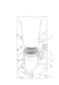
まず、製造方法の少なくともいくつかのステップに使用される超音波デバイス1の実施形態の一般的な構成を説明するために図1を参照する。
First, reference is made to FIG. 1 to describe the general configuration of an embodiment of an
超音波デバイス1は、既知の方法で、超音波電源と、コンバータと、ブースタと、加工面5を有する超音波ホーン3と、を備える。更に、超音波デバイス1は、本実施例では、巻回電池セル本体10を固定するための固定具7を備える。コントローラは、超音波デバイスが製造方法の少なくともいくつかのステップを実施し得るように、適合される。
The
巻回電池セル本体10は、第1の電極、セパレータ、及び第2の電極の層を備える。例えば、第1の電極は、カソードであってもよく、第2の電極は、アノードであってもよい。以下では、理解を容易にするために、カソード及びアノードという用語は、第1の電極及び第2の電極を示すために使用される。カソード及びアノードは、セパレータの両側に配置される。必要に応じて、例えば第1の電極のセパレータと反対側、又は第2の電極のセパレータと反対側に、層中に更なるセパレータが存在してもよい。
The wound
層は、複数の巻線で中心長手方向軸周りに巻き回される。したがって、本発明の製造方法の出発点は、一般に知られているように、巻き回された、又は巻かれた電池セル本体である。このような巻回電池セル本体は、最初に説明したように、その上にペーストを有する巻き上げられた金属箔によって形成されてもよい。また、上方から見て、すなわち、中心長手方向軸に沿って見て、巻回電池セル本体の層は、渦巻状である。したがって、層と中心長手方向軸との間の径方向距離は連続的に変化する。 The layers are wound around a central longitudinal axis with a number of windings. The starting point of the manufacturing method of the present invention is therefore a wound or rolled battery cell body, as is generally known. Such a wound battery cell body may be formed by a rolled up metal foil having a paste thereon, as initially described. Also, when viewed from above, i.e. along the central longitudinal axis, the layers of the wound battery cell body are spiral. The radial distance between the layers and the central longitudinal axis therefore varies continuously.
更に、カソード及びアノードの少なくとも一方は、長手方向の一方の前端に延在する導電性部分を備える。図1乃至4に関して、導電性部分12は、ホーン3の加工面5と対向して配置され、すなわち、導電性部分12は、加工面5に対向しており、逆もまた同様である。好ましくは、導電性部分は、金属箔を備える、又は金属箔からなる。
Furthermore, at least one of the cathode and anode comprises a conductive portion extending to one longitudinal front end. With reference to Figs. 1-4, the
また、巻回電池セル本体10は、円筒ジャケット30を備える。特に好ましくは、ジャケット30は、巻回電池セル本体10の延長部よりも長手方向の延長部が小さい。言い換えれば、ジャケット30の長手方向延長部は、好ましくは、巻回電池セル本体10の長手方向長さから、初期状態の導電性部分12の長さを引いたものに対応するように選択される。このようなジャケットの使用は、巻回電池セル本体10を超音波デバイス1の側面に固定する際に、例えばクランプによって固定した場合に、巻回電池セル本体10が損傷しないという利点がある。これは、損傷のリスク、及び標準以下の商品の製造を減少させる。2つの巻回電池セル本体10の例を図9に示す。
The wound
図2によれば、巻回電池セル本体10を設け、初期位置で超音波デバイス1内に配置した。これは、図10に示す製造方法のステップA及びBに対応する。図2で分かるように、配置するステップは、特に固定具7によるクランプによって、巻回電池セル本体を側面で固定するステップB1を含んでいる。
According to FIG. 2, a wound
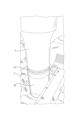
次に、ステップCにおいて、巻回電池セル本体10及びホーン3を、初期位置から加工位置まで互いに対して移動させる。図3は、第1の中間位置を示す。ここで、超音波デバイス1の固定具7で、巻回電池セル本体10を安定した位置に維持しつつ、ホーン3を中心長手方向軸に沿って、巻回電池セル本体10に向かって移動させた。図4は、ホーン3の加工面5が巻回電池セル本体10の前端で導電性部分12に当接して、生じる加工位置を示している。
Next, in step C, the wound
これに関して、加工面は断面が円形に設計されており、ホーン3の加工面の径方向の延長部が、巻回電池セル本体10の径方向の延長部に対応することに留意しなければならない。それにもかかわらず、好ましい実施形態によれば、ホーンの断面はまた、角形でもよい。更に、特に加工面5が、巻回電池セル本体10の前端を越えて少なくとも約3乃至5mm延在するように、ホーン3の加工面5の寸法は、巻回電池セル本体10の前端の寸法に適合されてもよい。ホーン3の異なる断面形状により、ホーン3を、好ましい用途及び巻回電池セル本体10に適合し得る。いずれの場合も、中心長手方向軸に垂直なホーン3の特定の延長部、特に少なくとも3乃至5mmの延長部は、特に、この延長部に起因して、導電性部分12の極めて信頼性の高い変形、特に曲げを達成することができるため、有利であることが証明されている。
In this regard, it must be noted that the machining surface is designed circular in cross section, the radial extension of the machining surface of the
ここで、ステップDでは、超音波振動を発生させて、巻回電池セル本体10の前端の導電性部分12に印加するように通電されるホーン3によって、巻回電池セル本体10が加工される。超音波デバイス1の好ましい実施形態では、加工範囲は、約15乃至40kHz、好ましくは約15乃至30kHz、更に好ましくは約20kHzである。具体的には、これらの加工範囲は、一方では巻回電池セル本体10の導電性部分12への超音波の印加を保証し、他方では径方向に隣接する導電性部分の確実な接続を容易にする。
Now, in step D, the wound
ステップDにおける超音波の印加中、ホーン3は、中心長手方向軸に沿って、巻回電池セル本体に向かって更に移動され、その結果、導電性部分の変形、好ましくは曲げ、特に好ましくは導電性部分の径方向内側への曲げをもたらす。図5は、ここでは加工された巻回電池セル本体20である巻回電池セル本体と、加工ステップの終了時のホーン3とを示している。これに関して、超音波の印加、及び加工ステップ中のホーン3の更なる移動は、同時に又は交互に行われ得ることに留意しなければならない。
During the application of ultrasonic waves in step D, the
特に、加工ステップDは、時間、経路、力、振幅のパラメータのうちの少なくとも1つによって制御される。例えば、導電性部分12が最初に長手方向に1mmの延長部を有する場合、ホーン3が加工ステップ中に移動する経路は、例えば最大でも1mmである。代替として、ホーン3によって印加される力、又はホーン3によって導電性部分12に印加される超音波振動の振幅を、一次パラメータとして使用してもよい。これに関して、一次パラメータという用語は、方法を制御するために主に使用されるパラメータを示すために使用されるが、他のパラメータが追加的に使用されてもよい。これにより、例えば、層の厚さ、層若しくは導電性部分12に使用される材料、又は層若しくは導電性部分12の長手方向の延長部に応じて、製造方法を、加工される巻回電池セル本体10に適合させてもよい。
In particular, the processing step D is controlled by at least one of the following parameters: time, path, force, amplitude. For example, if the
加工ステップDの後に、径方向に隣接する変形された導電性部分22は、好ましくは、互いに固定的に接続され、特にそれらは互いに溶接される。固定された接続により、接続は、極めて信頼性が高く、車両又は同様の用途でそれぞれ加工された巻回電池セル本体20の使用中の振動などに対して耐性がある。
After the processing step D, the radially adjacent deformed
更に、加工ステップDが完了し、加工された巻回電池セル本体20が生じた後、ステップEにおいて、ホーン3及び加工された巻回電池セル本体20は、加工位置から取り外し位置まで互いに対して移動される。好ましくは、上記に関して、ホーン3及び加工された巻回電池セル本体20の移動は、中心長手方向軸に沿って生じる。
Furthermore, after processing step D is completed and the processed wound
図6は、移動ステップE中の第2の中間位置を示している。この図で分かるように、変形された導電性部分22が、ホーン3による加工ステップ中に、導電性部分22が径方向内側に曲げられるように変形し、これにより、加工された電池セル本体20の長手方向の延長部が小さくなる。また、径方向に隣接する変形された導電性部分22は、加工ステップの後に互いに接触する。導電性部分の径方向内側への曲げは、最初に提供された巻回電池セル本体20と比較して、加工された巻回電池セル本体10の径方向寸法が大きくないという利点を有する。
Figure 6 shows the second intermediate position during the moving step E. As can be seen in this figure, the deformed
更に、図6で分かるように、ホーン3の加工面5は、巻回電池セル本体10に適合した輪郭を備える。本実施例では、ホーン3の加工面5は、2段の輪郭を有する。したがって、加工面5は、導電性部分12を変形させるように径方向外側に形成され、径方向内側には、加工面5に凹部が存在し、これにより、導電性部分12が径方向内側に変形しないようにする。更に、ローレットは、径方向に隣接する導電性部分12間の接触の信頼性を更に高める形成された輪郭として存在してもよい。また、加工面5の輪郭は、ホーン3の断面に応じて、円錐形状又はピラミッド形状を有してもよい。いずれの場合も、円錐又はピラミッド形状の仮想先端がホーン3内に配置されて、これにより、加工面5が、それぞれ成形されたくぼみを備えることが好ましい。
6, the
取り外し位置では、ホーン3の加工面5と加工された巻回電池セル本体20との間の距離が長くなる。例えば、取り外し位置は、上述の初期位置と同様である。
In the removal position, the distance between the
最後に、ステップFにおいて、加工された巻回電池セル本体20が超音波デバイス1から取り外される。この目的のために、電池セル本体が最初に側面に固定されたとき、ここで、側面における固定、例えばクランプがステップF1において解放される。これにより、加工された巻回電池セル本体20は、超音波デバイス1から取り外され、更に電池製造用に処理され得る。
Finally, in step F, the processed wound
図7及び図8は、超音波によって加工された変形された導電性部分22を有する電池セルのため、結果として得られる中間製品の異なる実施形態を示している。
Figures 7 and 8 show different embodiments of the resulting intermediate product for a battery cell having a deformed
この製造方法及び超音波デバイス1の利点は、巻回電池セル本体10の導電性部分12を、超音波デバイス1のホーン3によって、容易で、確実に変形し得ることである。更に、超音波の印加により、隣接する変形された導電性部分22間の確実な接続が、結果として得られる。
The advantage of this manufacturing method and
1 超音波デバイス
3 ホーン
5 加工面
7 固定具
10 巻回電池セル本体
12 導電性部分
20 加工された巻回電池セル本体
22 変形された導電性部分
30 ジャケット
1
Claims (13)
a.第1の電極、セパレータ、及び第2の電極の層が複数の巻線で中心長手方向軸周りに巻き回される巻回電池セル本体(10)を提供するステップ(A)であって、前記第1の電極及び前記第2の電極の一方が、前記長手方向の一方の前端に延在する導電性部分(12)を備える、ステップ(A)と、
b.前記巻回電池セル本体(10)を初期位置で超音波デバイス(1)内に配置するステップ(B)であって、これにより、前記導電性部分(12)を有する前記巻回電池セル本体(10)の前端が、前記超音波デバイス(1)のホーン(3)の前端加工面(5)に対向する、ステップ(B)と、
c.前記巻回電池セル本体(10)及び前記ホーン(3)を、前記中心長手方向軸に沿って、前記初期位置から、前記ホーン(3)の前端加工面(5)が前記巻回電池セル本体(10)の前端に当接する加工位置まで互いに対して移動させるステップ(C)と、続いて、
d.前記巻回電池セル本体(10)の前端の導電性部分(12)に少なくとも部分的に超音波を印加することによって、前記巻回電池セル本体(10)を加工するステップ(D)であって、これにより、前記導電性部分(12)が、前記ホーン(3)によって、前記巻回電池セル本体(10)の前端で少なくとも部分的に変形され、加工された巻回電池セル本体(20)が結果として得られる、ステップ(D)と、その後、
e.前記加工された巻回電池セル本体(20)及び前記ホーン(3)を、前記中心長手方向軸に沿って、前記加工位置から取り外し位置に互いに対して移動させるステップ(E)と、
f.前記加工された巻回電池セル本体(20)を前記超音波デバイス(1)から取り外すステップ(F)と、
を含む、製造方法。 A method for manufacturing an intermediate product for a battery cell by ultrasonic waves, comprising the steps of:
(A) providing a wound battery cell body (10) having a layer of a first electrode, a separator, and a second electrode wound about a central longitudinal axis with a plurality of windings, one of the first electrode and the second electrode including a conductive portion (12) extending to one longitudinal front end;
b. Step (B) of placing the wound battery cell body (10) in an initial position in an ultrasonic device (1), whereby a front end of the wound battery cell body (10) having the conductive portion (12) faces a front end processing surface (5) of a horn (3) of the ultrasonic device (1);
(c) moving the wound battery cell body (10) and the horn (3) relative to each other along the central longitudinal axis from the initial position to a processing position in which a front end processing surface (5) of the horn (3) abuts against a front end of the wound battery cell body (10);
(D) processing the wound battery cell body (10) by at least partially applying ultrasonic waves to the conductive portion (12) at the front end of the wound battery cell body (10), whereby the conductive portion (12) is at least partially deformed at the front end of the wound battery cell body (10) by the horn (3), resulting in a processed wound battery cell body (20); and then:
(e) moving the processed wound battery cell body (20) and the horn (3) relative to one another along the central longitudinal axis from the processing position to a removal position;
f. Removing the processed wound battery cell body (20) from the ultrasonic device (1);
A manufacturing method comprising:
Applications Claiming Priority (2)
| Application Number | Priority Date | Filing Date | Title |
|---|---|---|---|
| EP22158272.9A EP4235885A1 (en) | 2022-02-23 | 2022-02-23 | Manufacturing method of an intermediate product for a battery cell, intermediate product for a battery cell and ultrasonic device for manufacturing the intermediate product |
| EP22158272.9 | 2022-02-23 |
Publications (2)
| Publication Number | Publication Date |
|---|---|
| JP2023122629A JP2023122629A (en) | 2023-09-04 |
| JP7585366B2 true JP7585366B2 (en) | 2024-11-18 |
Family
ID=80448438
Family Applications (1)
| Application Number | Title | Priority Date | Filing Date |
|---|---|---|---|
| JP2023019994A Active JP7585366B2 (en) | 2022-02-23 | 2023-02-13 | Method for manufacturing intermediate products for battery cells, intermediate products for battery cells, and ultrasonic device for manufacturing the intermediate products |
Country Status (5)
| Country | Link |
|---|---|
| US (1) | US20230268558A1 (en) |
| EP (1) | EP4235885A1 (en) |
| JP (1) | JP7585366B2 (en) |
| KR (1) | KR102842761B1 (en) |
| CN (1) | CN116646614A (en) |
Citations (1)
| Publication number | Priority date | Publication date | Assignee | Title |
|---|---|---|---|---|
| JP2011134641A (en) | 2009-12-25 | 2011-07-07 | Toyota Motor Corp | Battery |
Family Cites Families (4)
| Publication number | Priority date | Publication date | Assignee | Title |
|---|---|---|---|---|
| JP2002184373A (en) * | 2000-12-18 | 2002-06-28 | Gs-Melcotec Co Ltd | Battery pack manufacturing method and welding device |
| US11482711B2 (en) * | 2017-09-09 | 2022-10-25 | Soteria Battery Innovation Group, Inc. | Tabless cell utilizing metallized film current collectors |
| CN207517807U (en) * | 2017-11-23 | 2018-06-19 | 武汉逸飞激光设备有限公司 | A kind of battery core rubs flat equipment |
| JP7649736B2 (en) | 2018-11-05 | 2025-03-21 | テスラ,インコーポレイテッド | Cell with Tabless Structure Electrode |
-
2022
- 2022-02-23 EP EP22158272.9A patent/EP4235885A1/en active Pending
-
2023
- 2023-02-07 CN CN202310141395.6A patent/CN116646614A/en active Pending
- 2023-02-13 JP JP2023019994A patent/JP7585366B2/en active Active
- 2023-02-21 KR KR1020230022811A patent/KR102842761B1/en active Active
- 2023-02-23 US US18/113,119 patent/US20230268558A1/en active Pending
Patent Citations (1)
| Publication number | Priority date | Publication date | Assignee | Title |
|---|---|---|---|---|
| JP2011134641A (en) | 2009-12-25 | 2011-07-07 | Toyota Motor Corp | Battery |
Also Published As
| Publication number | Publication date |
|---|---|
| EP4235885A1 (en) | 2023-08-30 |
| JP2023122629A (en) | 2023-09-04 |
| KR102842761B1 (en) | 2025-08-04 |
| US20230268558A1 (en) | 2023-08-24 |
| KR20230126656A (en) | 2023-08-30 |
| CN116646614A (en) | 2023-08-25 |
Similar Documents
| Publication | Publication Date | Title |
|---|---|---|
| KR102262668B1 (en) | Cylindrical electrochemical cells and method of manufacture | |
| JP6089784B2 (en) | Prismatic secondary battery | |
| US10741819B2 (en) | Electricity storage device and method for manufacturing electricity storage device | |
| US6275372B1 (en) | Energy storage device | |
| US20070188978A1 (en) | Connecting structure between electrode and lead, electric double layer capacitor having the same, and method for manufacturing the capacitor | |
| EP1983595B1 (en) | Connection system for an electrochemical cell | |
| WO2009123081A1 (en) | Winding type battery and method for manufacturing winding type battery | |
| US9954245B2 (en) | Mandrel for electrode assemblies | |
| US9843067B2 (en) | Methods for electrode assemblies including at least one insulative portion | |
| JP7585366B2 (en) | Method for manufacturing intermediate products for battery cells, intermediate products for battery cells, and ultrasonic device for manufacturing the intermediate products | |
| CN102576849A (en) | Battery fabrication method | |
| CN119585069A (en) | Ultrasonic welding device and welding structure | |
| ES2650922T3 (en) | Manufacturing procedure of an electric energy storage assembly | |
| JP2575195B2 (en) | Ultra high voltage electrical energy storage device | |
| US9812698B2 (en) | Method for manufacturing a connecting contact for an electrode of an electrochemical store, method for manufacturing an electrochemical store, and electrochemical store | |
| JPH1197301A (en) | Cylindrical power storage device and method of manufacturing the same | |
| JP2009272244A (en) | Battery and method for manufacturing the same | |
| US12278398B2 (en) | Sealed battery and method of manufacturing sealed battery | |
| KR20050044870A (en) | Method for joining lacquered wires in an electrically conducting manner | |
| EP4571805A1 (en) | Electricity storage device and method for manufacturing same | |
| JP5318457B2 (en) | Electrode focusing device | |
| JP7806443B2 (en) | Electricity storage device and method for manufacturing the same | |
| EP4349497A2 (en) | Converter for an ultrasonic welding device having increased arc resistance | |
| KR20250104694A (en) | Electrode sheet and electrode assembly wound thereon | |
| KR20250130321A (en) | Battery cell and manufacturing method thereof |
Legal Events
| Date | Code | Title | Description |
|---|---|---|---|
| A621 | Written request for application examination |
Free format text: JAPANESE INTERMEDIATE CODE: A621 Effective date: 20230220 |
|
| A521 | Request for written amendment filed |
Free format text: JAPANESE INTERMEDIATE CODE: A523 Effective date: 20230301 |
|
| A977 | Report on retrieval |
Free format text: JAPANESE INTERMEDIATE CODE: A971007 Effective date: 20240319 |
|
| A131 | Notification of reasons for refusal |
Free format text: JAPANESE INTERMEDIATE CODE: A131 Effective date: 20240423 |
|
| A521 | Request for written amendment filed |
Free format text: JAPANESE INTERMEDIATE CODE: A523 Effective date: 20240711 |
|
| TRDD | Decision of grant or rejection written | ||
| A01 | Written decision to grant a patent or to grant a registration (utility model) |
Free format text: JAPANESE INTERMEDIATE CODE: A01 Effective date: 20241015 |
|
| A61 | First payment of annual fees (during grant procedure) |
Free format text: JAPANESE INTERMEDIATE CODE: A61 Effective date: 20241106 |
|
| R150 | Certificate of patent or registration of utility model |
Ref document number: 7585366 Country of ref document: JP Free format text: JAPANESE INTERMEDIATE CODE: R150 |