JP7581386B2 - Network node, communication method and transport - Google Patents
Network node, communication method and transport Download PDFInfo
- Publication number
- JP7581386B2 JP7581386B2 JP2022577993A JP2022577993A JP7581386B2 JP 7581386 B2 JP7581386 B2 JP 7581386B2 JP 2022577993 A JP2022577993 A JP 2022577993A JP 2022577993 A JP2022577993 A JP 2022577993A JP 7581386 B2 JP7581386 B2 JP 7581386B2
- Authority
- JP
- Japan
- Prior art keywords
- teid
- gnb
- network
- unit
- transport
- Prior art date
- Legal status (The legal status is an assumption and is not a legal conclusion. Google has not performed a legal analysis and makes no representation as to the accuracy of the status listed.)
- Active
Links
Images


Classifications
-
- H—ELECTRICITY
- H04—ELECTRIC COMMUNICATION TECHNIQUE
- H04W—WIRELESS COMMUNICATION NETWORKS
- H04W76/00—Connection management
- H04W76/10—Connection setup
- H04W76/12—Setup of transport tunnels
Landscapes
- Engineering & Computer Science (AREA)
- Computer Networks & Wireless Communication (AREA)
- Signal Processing (AREA)
- Mobile Radio Communication Systems (AREA)
Description
本発明は、無線通信システムにおけるネットワークノード、通信方法及びトランスポートに関する。 The present invention relates to a network node, a communication method and transport in a wireless communication system.
LTE(Long Term Evolution)の後継システムであるNR(New Radio)(「5G」ともいう。)においては、要求条件として、大容量のシステム、高速なデータ伝送速度、低遅延、多数の端末の同時接続、低コスト、省電力等を満たす技術が検討されている(例えば非特許文献1)。For NR (New Radio) (also known as "5G"), the successor system to LTE (Long Term Evolution), technologies are being considered that meet the requirements of a large-capacity system, high data transmission speed, low latency, simultaneous connection of a large number of terminals, low cost, and low power consumption (for example, non-patent document 1).
NRネットワークにおける既存仕様では、gNB-DU(next generation Node B - Distributed Unit)、gNB-CU-UP(next generation Node B - Central Unit - User Plane)及びUPF(User plane function)を所有するPLMN(Public Land Mobile Network)に対応する移動体通信事業者が、gNB-DUとgNB-CU-UPの間及びgNB-CU-UPとUPFの間のユーザデータ伝送路を所有するとの暗黙の前提がある。 In the existing specifications for the NR network, there is an implicit assumption that a mobile communications operator corresponding to a PLMN (Public Land Mobile Network) that owns a gNB-DU (next generation Node B - Distributed Unit), gNB-CU-UP (next generation Node B - Central Unit - User Plane) and UPF (User plane function) owns the user data transmission paths between the gNB-DU and gNB-CU-UP and between the gNB-CU-UP and the UPF.
NRネットワークにおいて、gNB-DUとgNB-CU-UPの間及びgNB-CU-UPとUPFの間のユーザデータ伝送路が、PLMNに対応する移動体通信事業者とは独立した伝送網事業者が所有する場合がある。しかしながら、他PLMNに対応する移動体通信事業者が、当該ユーザデータ伝送路を使用するインタフェースが仕様上確立されていなかった。In the NR network, the user data transmission paths between the gNB-DU and gNB-CU-UP, and between the gNB-CU-UP and UPF, may be owned by a transmission network operator independent of the mobile communications operator corresponding to the PLMN. However, the specifications did not establish an interface for mobile communications operators corresponding to other PLMNs to use the user data transmission paths.
本発明は上記の点に鑑みてなされたものであり、無線通信システムにおいて、ユーザデータ伝送路の使用効率を向上させることを目的とする。 The present invention has been made in consideration of the above points, and aims to improve the utilization efficiency of user data transmission paths in wireless communication systems.
開示の技術によれば、PDU(Protocol Data Unit)セッションを確立するとき、UPF(User Plane Function)及び伝送網事業者を選択し、前記伝送網事業者及び前記伝送網事業者が提供するサービス種別を示す情報をエンコードしてネットワークインスタンスを決定する制御部と、前記ネットワークインスタンスを前記UPFに送信する送信部と、
前記UPFから上りリンクに対応する第1のTEID(Tunnel Endpoint Identifier)を受信し、gNB-CU-CP(next generation Node B - Central Unit - Control Plane)から下りリンクに対応する第2のTEIDを受信する受信部とを有し、前記送信部は、データ伝送路において前記UPFとgNB-CU-UP(next generation Node B - Central Unit - User Plane)との間に設置されるトランスポートに、前記第1のTEIDと、前記第2のTEIDと、PLMN(Public Land Mobile Network)に対応するインタフェースを示す情報とを送信して、前記PDUセッションを確立するネットワークノードが提供される。
According to the disclosed technology, when establishing a PDU (Protocol Data Unit) session, a control unit selects a UPF (User Plane Function) and a transmission network operator, and encodes information indicating the transmission network operator and a service type provided by the transmission network operator to determine a network instance; and a transmission unit transmits the network instance to the UPF.
A network node is provided that has a receiving unit that receives a first TEID (Tunnel Endpoint Identifier) corresponding to the uplink from the UPF and receives a second TEID corresponding to the downlink from a gNB-CU-CP (next generation Node B - Central Unit - Control Plane), and the transmitting unit transmits the first TEID, the second TEID, and information indicating an interface corresponding to a PLMN (Public Land Mobile Network) to a transport installed between the UPF and a gNB-CU-UP (next generation Node B - Central Unit - User Plane) in a data transmission path, thereby establishing the PDU session.
加えて、SMF(Session Management Function)から上りリンクに対応する第1のTEID(Tunnel Endpoint Identifier)と、下りリンクに対応する第2のTEIDと、PLMN(Public Land Mobile Network)に対応するインタフェースを示す情報を受信する受信部と、前記第1のTEID、前記第2のTEID及び前記PLMNに対応するインタフェースを示す情報に基づいて、UPF(User Plane Function)とgNB-CU-UP(next generation Node B - Central Unit - User Plane)との間にデータ伝送路を設定する制御部とを有し、前記第1のTEIDは、前記UPFから前記SMFに送信され、前記第2のTEIDは、gNB-CU-CP(next generation Node B - Central Unit - Control Plane)から前記SMFに送信されるトランスポートが提供される。In addition, the system includes a receiving unit that receives from an SMF (Session Management Function) a first TEID (Tunnel Endpoint Identifier) corresponding to the uplink, a second TEID corresponding to the downlink, and information indicating an interface corresponding to a PLMN (Public Land Mobile Network), and a control unit that sets up a data transmission path between a UPF (User Plane Function) and a gNB-CU-UP (next generation Node B - Central Unit - User Plane) based on the first TEID, the second TEID, and the information indicating the interface corresponding to the PLMN, and a transport is provided in which the first TEID is transmitted from the UPF to the SMF and the second TEID is transmitted from the gNB-CU-CP (next generation Node B - Central Unit - Control Plane) to the SMF.
さらに、開示の技術によれば、PDUセッションを確立するとき、gNB-CU-UP及び伝送網事業者を選択し、前記伝送網事業者及び前記伝送網事業者が提供するサービス種別を示す情報をエンコードしてネットワークインスタンスを決定する制御部と、前記ネットワークインスタンスを前記gNB-CU-UPに送信する送信部と、前記gNB-CU-UPから上りリンクに対応する第5のTEIDを受信し、gNB-DU(next generation Node B - Distributed Unit)から下りリンクに対応する第6のTEIDを受信する受信部とを有し、前記送信部は、データ伝送路において前記gNB-CU-UPとgNB-DUとの間に設置されるトランスポートに、前記第5のTEIDと、前記第6のTEIDと、PLMNに対応するインタフェースを示す情報とを送信して、前記PDUセッションを確立するネットワークノードが提供される。 Furthermore, according to the disclosed technology, a network node is provided that, when establishing a PDU session, has a control unit that selects a gNB-CU-UP and a transmission network operator, and determines a network instance by encoding information indicating the transmission network operator and the service type provided by the transmission network operator, a transmitting unit that transmits the network instance to the gNB-CU-UP, and a receiving unit that receives a fifth TEID corresponding to the uplink from the gNB-CU-UP and a sixth TEID corresponding to the downlink from a gNB-DU (next generation Node B - Distributed Unit), wherein the transmitting unit transmits the fifth TEID, the sixth TEID, and information indicating an interface corresponding to a PLMN to a transport installed between the gNB-CU-UP and the gNB-DU in a data transmission path, thereby establishing the PDU session.
加えて、gNB-CU-CP(next generation Node B - Central Unit - Control Plane)から上りリンクに対応する第5のTEID(Tunnel Endpoint Identifier)と、下りリンクに対応する第6のTEIDと、PLMN(Public Land Mobile Network)に対応するインタフェースを示す情報を受信する受信部と、前記第5のTEID、前記第6のTEID及び前記PLMNに対応するインタフェースを示す情報に基づいて、gNB-CU-UP(next generation Node B - Central Unit - User Plane)とgNB-DU(next generation Node B - Distributed Unit)との間にデータ伝送路を設定する制御部とを有し、前記第5のTEIDは、前記gNB-CU-UPから前記gNB-CU-CPに送信され、前記第6のTEIDは、前記gNB-DUから前記gNB-CU-CPに送信されるトランスポートが提供される。In addition, the device has a receiving unit that receives a fifth TEID (Tunnel Endpoint Identifier) corresponding to the uplink from a gNB-CU-CP (next generation Node B - Central Unit - Control Plane), a sixth TEID corresponding to the downlink, and information indicating an interface corresponding to a PLMN (Public Land Mobile Network), and a control unit that sets up a data transmission path between a gNB-CU-UP (next generation Node B - Central Unit - User Plane) and a gNB-DU (next generation Node B - Distributed Unit) based on the fifth TEID, the sixth TEID, and the information indicating the interface corresponding to the PLMN, and transport is provided in which the fifth TEID is transmitted from the gNB-CU-UP to the gNB-CU-CP and the sixth TEID is transmitted from the gNB-DU to the gNB-CU-CP.
開示の技術によれば、無線通信システムにおいて、ユーザデータ伝送路の使用効率を向上させることができる。 The disclosed technology makes it possible to improve the utilization efficiency of user data transmission paths in wireless communication systems.
以下、図面を参照して本発明の実施の形態を説明する。なお、以下で説明する実施の形態は一例であり、本発明が適用される実施の形態は、以下の実施の形態に限られない。Hereinafter, an embodiment of the present invention will be described with reference to the drawings. Note that the embodiment described below is an example, and the embodiment to which the present invention is applicable is not limited to the following embodiment.
本発明の実施の形態の無線通信システムの動作にあたっては、適宜、既存技術が使用される。ただし、当該既存技術は、例えば既存のLTEであるが、既存のLTEに限られない。また、本明細書で使用する用語「LTE」は、特に断らない限り、LTE-Advanced、及び、LTE-Advanced以降の方式(例:NR)を含む広い意味を有するものとする。Existing technology is used as appropriate in the operation of the wireless communication system of the embodiment of the present invention. However, the existing technology is, for example, the existing LTE, but is not limited to the existing LTE. Furthermore, the term "LTE" used in this specification has a broad meaning including LTE-Advanced and systems subsequent to LTE-Advanced (e.g., NR) unless otherwise specified.
また、以下で説明する本発明の実施の形態では、既存のLTEで使用されているSS(Synchronization signal)、PSS(Primary SS)、SSS(Secondary SS)、PBCH(Physical broadcast channel)、PRACH(Physical random access channel)、PDCCH(Physical Downlink Control Channel)、PDSCH(Physical Downlink Shared Channel)、PUCCH(Physical Uplink Control Channel)、PUSCH(Physical Uplink Shared Channel)等の用語を使用する。これは記載の便宜上のためであり、これらと同様の信号、機能等が他の名称で呼ばれてもよい。また、NRにおける上述の用語は、NR-SS、NR-PSS、NR-SSS、NR-PBCH、NR-PRACH、NR-PDCCH、NR-PDSCH、NR-PUCCH、NR-PUSCH等に対応する。ただし、NRに使用される信号であっても、必ずしも「NR-」と明記しない。In addition, in the embodiment of the present invention described below, terms such as SS (Synchronization signal), PSS (Primary SS), SSS (Secondary SS), PBCH (Physical broadcast channel), PRACH (Physical random access channel), PDCCH (Physical Downlink Control Channel), PDSCH (Physical Downlink Shared Channel), PUCCH (Physical Uplink Control Channel), and PUSCH (Physical Uplink Shared Channel) used in existing LTE are used. This is for convenience of description, and similar signals, functions, etc. may be called by other names. In addition, the above-mentioned terms in NR correspond to NR-SS, NR-PSS, NR-SSS, NR-PBCH, NR-PRACH, NR-PDCCH, NR-PDSCH, NR-PUCCH, NR-PUSCH, etc. However, even if a signal is used in NR, it is not necessarily specified as "NR-".
また、本発明の実施の形態において、複信(Duplex)方式は、TDD(Time Division Duplex)方式でもよいし、FDD(Frequency Division Duplex)方式でもよいし、又はそれ以外(例えば、Flexible Duplex等)の方式でもよい。 In addition, in an embodiment of the present invention, the duplex method may be a TDD (Time Division Duplex) method, an FDD (Frequency Division Duplex) method, or another method (e.g., Flexible Duplex, etc.).
また、本発明の実施の形態において、無線パラメータ等が「設定される(Configure)」とは、所定の値が予め設定(Pre-configure)されることであってもよいし、基地局10又は端末20から通知される無線パラメータが設定されることであってもよい。
In addition, in an embodiment of the present invention, when radio parameters, etc. are "configured," this may mean that predetermined values are pre-configured, or that radio parameters notified from the
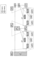
図1は、通信システムの例を説明するための図である。図1に示されるように、通信システムは、端末20であるUE、複数のネットワークノード30から構成される。以下、機能ごとに1つのネットワークノード30が対応するものとするが、複数の機能を1つのネットワークノード30が実現してもよいし、複数のネットワークノード30が1つの機能を実現してもよい。また、以下に記載する「接続」は、論理的な接続であってもよいし、物理的な接続であってもよい。
Figure 1 is a diagram for explaining an example of a communication system. As shown in Figure 1, the communication system is composed of a UE, which is a
RAN(Radio Access Network)は、無線アクセス機能を有するネットワークノード30であり、基地局10を含んでもよく、UE、AMF(Access and Mobility Management Function)及びUPF(User plane function)と接続される。AMFは、RANインタフェースの終端、NAS(Non-Access Stratum)の終端、登録管理、接続管理、到達性管理、モビリティ管理等の機能を有するネットワークノード30である。UPFは、DN(Data Network)と相互接続する外部に対するPDU(Protocol Data Unit)セッションポイント、パケットのルーティング及びフォワーディング、ユーザプレーンのQoS(Quality of Service)ハンドリング等の機能を有するネットワークノード30である。UPF及びDNは、ネットワークスライスを構成する。本発明の実施の形態における無線通信ネットワークでは、複数のネットワークスライスが構築されている。
The RAN (Radio Access Network) is a network node 30 having a radio access function, which may include a
AMFは、UE、RAN、SMF(Session Management function)、NSSF(Network Slice Selection Function)、NEF(Network Exposure Function)、NRF(Network Repository Function)、UDM(Unified Data Management)、AUSF(Authentication Server Function)、PCF(Policy Control Function)、AF(Application Function)と接続される。AMF、SMF、NSSF、NEF、NRF、UDM、AUSF、PCF、AFは、各々のサービスに基づくインタフェース、Namf、Nsmf、Nnssf、Nnef、Nnrf、Nudm、Nausf、Npcf、Nafを介して相互に接続されるネットワークノード30である。The AMF is connected to the UE, RAN, SMF (Session Management function), NSSF (Network Slice Selection Function), NEF (Network Exposure Function), NRF (Network Repository Function), UDM (Unified Data Management), AUSF (Authentication Server Function), PCF (Policy Control Function), and AF (Application Function). The AMF, SMF, NSSF, NEF, NRF, UDM, AUSF, PCF, and AF are network nodes 30 that are mutually connected via interfaces, Namf, Nsmf, Nnssf, Nnef, Nnrf, Nudm, Nausf, Npcf, and Naf, based on their respective services.
SMFは、セッション管理、UEのIP(Internet Protocol)アドレス割り当て及び管理、DHCP(Dynamic Host Configuration Protocol)機能、ARP(Address Resolution Protocol)プロキシ、ローミング機能等の機能を有するネットワークノード30である。NEFは、他のNF(Network Function)に能力及びイベントを通知する機能を有するネットワークノード30である。NSSFは、UEが接続するネットワークスライスの選択、許可されるNSSAI(Network Slice Selection Assistance Information)の決定、設定されるNSSAIの決定、UEが接続するAMFセットの決定等の機能を有するネットワークノード30である。PCFは、ネットワークのポリシ制御を行う機能を有するネットワークノード30である。AFは、アプリケーションサーバを制御する機能を有するネットワークノード30である。NRFは、サービスを提供するNFインスタンスを発見する機能を有するネットワークノード30である。UDMは、加入者データ及び認証データを管理するネットワークノード30である。UDMは、当該データを保持するUDR(User Data Repository)と接続される。The SMF is a network node 30 having functions such as session management, UE IP (Internet Protocol) address allocation and management, DHCP (Dynamic Host Configuration Protocol) function, ARP (Address Resolution Protocol) proxy, and roaming function. The NEF is a network node 30 having a function of notifying other NFs (Network Functions) of capabilities and events. The NSSF is a network node 30 having functions such as selecting a network slice to which the UE connects, determining an allowed NSSAI (Network Slice Selection Assistance Information), determining an NSSAI to be set, and determining an AMF set to which the UE connects. The PCF is a network node 30 having a function of controlling the policy of the network. The AF is a network node 30 having a function of controlling an application server. The NRF is a network node 30 having a function of discovering an NF instance that provides a service. The UDM is a network node 30 that manages subscriber data and authentication data. The UDM is connected to a UDR (User Data Repository) that holds the data.
NRネットワークにおける既存仕様では、gNB-DU(next generation Node B - Distributed Unit)、gNB-CU-UP(next generation Node B - Central Unit - User Plane)及びUPF(User plane function)を所有するPLMN(Public Land Mobile Network)に対応する移動体通信事業者が、gNB-DUとgNB-CU-UPの間及びgNB-CU-UPとUPFの間のユーザデータ伝送路を所有するとの暗黙の前提がある。また、伝送路へのトラヒック特性の通知もDSCP(Differentiated Services Code Point)値によるのみである。 In the existing specifications for the NR network, there is an implicit assumption that a mobile communications operator corresponding to a PLMN (Public Land Mobile Network) that owns a gNB-DU (next generation Node B - Distributed Unit), a gNB-CU-UP (next generation Node B - Central Unit - User Plane), and a UPF (User plane function) owns the user data transmission path between the gNB-DU and the gNB-CU-UP and between the gNB-CU-UP and the UPF. In addition, notification of traffic characteristics to the transmission path is only by the DSCP (Differentiated Services Code Point) value.
すなわち、NRネットワークにおける既存仕様において、伝送網事業者の概念がなく、伝送網事業者が複数PLMNからのトラヒックを呼毎に受け入れる方法がなく、トラヒック特性をオフパスで取得する伝送路を使用することができない。 In other words, in the existing specifications for NR networks, there is no concept of a transmission network operator, there is no way for a transmission network operator to accept traffic from multiple PLMNs on a call-by-call basis, and it is not possible to use transmission paths that obtain traffic characteristics off-path.
そこで、伝送路各部分を外部からは1つのUPF(以下、「トランスポート」という。)としてみなせるよう構成する。トランスポートは、1つのネットワークノードとして動作してもよいし、トランスポートは、さらに複数のネットワークノードから構成されてもよい。Therefore, each part of the transmission path is configured so that it can be viewed from the outside as a single UPF (hereinafter referred to as "transport"). The transport may operate as a single network node, or the transport may be further composed of multiple network nodes.
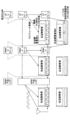
図2は、本発明の実施の形態におけるネットワーク構成の例を示す図である。図2に示されるように、gNB-CU-CP(next generation Node B - Central Unit - Control Plane)は、gNB-DUとgNB-CU-UPとの間にトランスポートを設定できるものとする。また、SMFは、gNB-CU-UPとUPFとの間にトランスポートを設定できるものとする。 Figure 2 is a diagram showing an example of a network configuration in an embodiment of the present invention. As shown in Figure 2, the gNB-CU-CP (next generation Node B - Central Unit - Control Plane) is capable of setting up transport between the gNB-DU and the gNB-CU-UP. In addition, the SMF is capable of setting up transport between the gNB-CU-UP and the UPF.
図2に示されるように、トランスポートは、以下に示される1)-3)の3部分から構成される。As shown in Figure 2, the transport consists of three parts: 1)-3) as shown below.
1)gNB-CU-CP又はSMFから指示を受けて、TEID(Tunnel Endpoint Identifier)を管理し、トラヒック特性をトランスポート内部に展開する部分。以下、「tSMF」という。 1) A part that receives instructions from the gNB-CU-CP or SMF, manages the TEID (Tunnel Endpoint Identifier), and deploys traffic characteristics inside the transport. Hereinafter referred to as "tSMF."
2)伝送路としてエッジ側に位置する部分。以下、「aUPF」という。 2) The part located on the edge side as a transmission path. Hereinafter referred to as "aUPF."
3)伝送路として中央側に位置する部分。以下、「bUPF」という。 3) The part located in the center as a transmission path. Hereinafter referred to as "bUPF."
図2に示されるように、トランスポートには、あるPLMNにおけるgNB-DU、gNB-CU-UP及びUPFと、他のPLMNにおけるgNB-DU、gNB-CU-UP及びUPFが接続可能である。As shown in Figure 2, a transport can connect a gNB-DU, gNB-CU-UP and UPF in one PLMN to a gNB-DU, gNB-CU-UP and UPF in another PLMN.
gNB-CU-CP又はSMFからトランスポートに送信する指示によって、要求元PLMNを区別可能とする。また、gNB-CU-CPからgNB-CU-UPに送信する指示又はSMFからUPFに送信する指示は、既存のネットワークインスタンスを含む。ネットワークインスタンスは、gNB-CU-CP又はSMFがトランスポートを提供する伝送網事業者名及び当該伝送網事業者が提供する伝送サービス種別を新規にエンコードしたものとする。The requesting PLMN can be distinguished by the instruction sent from the gNB-CU-CP or SMF to the transport. Furthermore, the instruction sent from the gNB-CU-CP to the gNB-CU-UP or the instruction sent from the SMF to the UPF includes an existing network instance. The network instance is a newly encoded name of the transmission network operator through which the gNB-CU-CP or SMF provides transport and the type of transmission service provided by the transmission network operator.
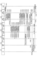
図3は、本発明の実施の形態における伝送路の例を示す図である。図3において、トランスポートは、コアUプレーンとRANUプレーンの間の伝送路と、RANUプレーンとRAN下位レイヤの間の伝送路とに対応する。図3に示されるように、あるPLMN及び他のPLMNが、同一の伝送網事業者が提供するトランスポートを利用することができる。また、あるPLMNは、複数の伝送網事業者が提供する複数のトランスポートを利用してもよい。例えば、図3に示されるように、伝送網事業者Bが提供するトランスポートは、あるPLMNの時刻同期信号トラヒックを収容する。 Figure 3 is a diagram showing an example of a transmission path in an embodiment of the present invention. In Figure 3, the transports correspond to the transmission path between the core U plane and the RANU plane, and the transmission path between the RANU plane and the RAN lower layer. As shown in Figure 3, a PLMN and another PLMN can use a transport provided by the same transmission network operator. Also, a PLMN may use multiple transports provided by multiple transmission network operators. For example, as shown in Figure 3, a transport provided by transmission network operator B accommodates time synchronization signal traffic of a PLMN.
本発明の実施の形態における通信手順は、以下に示される1)-5)のように実行される。 The communication procedure in an embodiment of the present invention is performed as follows: 1)-5).
1)PDUセッション確立時に、SMFは、例えばS-NSSAI(Single-Network Slice Selection Assistance Information)及びDNN(Data Network Name)に基づいて、適切なネットワークインスタンス値を設定する。SMFは、適切なUPFを選択し当該ネットワークインスタンス値を通知する。当該UPFは適切なインタフェースを選択する。当該インタフェースとは、TEIDであってもよい。SMFは、UPFとgNB-CU-UPとの間に設置される適切なトランスポートを選択し、要求元PLMN情報をtSMFに通知する。tSMFは、aUPF及びbUPFで当該PLMN向けにインタフェースを設定し、SMFに応答する。 1) When establishing a PDU session, the SMF sets an appropriate network instance value, for example based on S-NSSAI (Single-Network Slice Selection Assistance Information) and DNN (Data Network Name). The SMF selects an appropriate UPF and notifies it of the network instance value. The UPF selects an appropriate interface, which may be a TEID. The SMF selects an appropriate transport installed between the UPF and gNB-CU-UP and notifies the tSMF of the requesting PLMN information. The tSMF sets interfaces for the PLMN in the aUPF and bUPF and responds to the SMF.
2)SMFは、gNB-CU-CPにネットワークインスタンス値を通知する。gNB-CU-CPは、適切なgNB-CU-UPを選択し、当該ネットワークインスタンス値を通知する。当該gNB-CU-UPは適切なインタフェースを選択する。当該インタフェースとは、TEIDであってもよい。gNB-CU-CPは、gNB-CU-UPとgNB-DUとの間に設置される適切なトランスポートを選択し、要求元PLMN情報をtSMFに通知する。tSMFは、aUPF及びbUPFで当該PLMN向けにインタフェースを設定し、gNB-CU-CPに応答する。 2) The SMF notifies the gNB-CU-CP of the network instance value. The gNB-CU-CP selects an appropriate gNB-CU-UP and notifies it of the network instance value. The gNB-CU-UP selects an appropriate interface, which may be a TEID. The gNB-CU-CP selects an appropriate transport to be installed between the gNB-CU-UP and the gNB-DU, and notifies the tSMF of the requesting PLMN information. The tSMF configures interfaces for the PLMN in the aUPF and bUPF, and responds to the gNB-CU-CP.
3)gNB-CU-CPは、gNB-DUのULインタフェースを設定する。このときgNB-DUはスケジュール支援情報を得るため内部MAC(Medium Access Control)機能がスケジュールを確定してもよい。gNB-DUは、gNB-DUとgNB-RU(Remote Unit)の間の伝送路を管理するノード(例えば、PON(Passive Optical Network)の場合のOLT(Optical Line Terminal))に確定したトラヒック特性を通知してもよい。 3) The gNB-CU-CP configures the UL interface of the gNB-DU. At this time, the gNB-DU may determine the schedule using its internal MAC (Medium Access Control) function to obtain schedule assistance information. The gNB-DU may notify the determined traffic characteristics to a node that manages the transmission path between the gNB-DU and the gNB-RU (Remote Unit) (e.g., an OLT (Optical Line Terminal) in the case of a PON (Passive Optical Network)).
4)gNB-CU-CPは、gNB-CU-UPとgNB-DUとの間に設置されるトランスポートのDLインタフェースを設定する。このときSMFは、トランスポートにgNB-DUのMAC機能が確定したトラヒック特性を通知してもよい。 4) The gNB-CU-CP configures a transport DL interface between the gNB-CU-UP and the gNB-DU. At this time, the SMF may notify the transport of the traffic characteristics for which the gNB-DU's MAC function has been determined.
5)SMFは、UPFとgNB-CU-UPとの間に設置されるトランスポートのDLインタフェースを設定する。このときSMFは、トランスポートにgNB-DUのMAC機能が確定したトラヒック特性を通知してもよい。 5) The SMF configures a DL interface of the transport installed between the UPF and the gNB-CU-UP. At this time, the SMF may notify the transport of the traffic characteristics for which the MAC function of the gNB-DU has been determined.
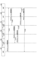
図4は、本発明の実施の形態におけるPDUセッション確立の例(1)を説明するためのシーケンス図である。図4において、UPF30BのULに対応するTEIDは1、bUPF30DのDLに対応するTEIDは2、ULに対応するTEIDは3、aUPF30EのDLに対応するTEIDは4、ULに対応するTEIDは5とする。 Figure 4 is a sequence diagram for explaining an example (1) of PDU session establishment in an embodiment of the present invention. In Figure 4, the TEID corresponding to the UL of UPF30B is 1, the TEID corresponding to the DL of bUPF30D is 2, the TEID corresponding to the UL is 3, the TEID corresponding to the DL of aUPF30E is 4, and the TEID corresponding to the UL is 5.
ステップS101において、UE20は、UL情報転送をgNB-DU10Cに送信する。続いて、gNB-DU10Cは、UL-RRCメッセージ転送をgNB-CU-CP10Aに送信する(S102)。続いて、gNB-CU-CP10Aは、UL-NASメッセージ転送をAMF30Fに送信する(S103)。In step S101,
ステップS104において、AMF30Fは、PDUセッション確立要求をSMF30Aに送信する。続いて、SMF30Aは、PDUセッション確立応答をAMF30Fに送信する(S105)。続いて、SMF30Aは、UPF選択及びトランスポート選択を実行する(S106)。続いて、SMF30Aは、PFCP(Packet Forwarding Control Protocol)セッション確立要求をUPF30Bに送信する(S107)。ステップS107におけるPFCPセッション確立要求は、SMFがS-NSSAI及びDNNに基づいて選択した適切なネットワークインスタンスを含む。当該ネットワークインスタンスは、トランスポートを提供する伝送網事業者名及び当該伝送網事業者が提供する伝送サービス種別(例えば、スロット割り当てあり決定的通信等)をエンコードしたものとする。続いて、UPF30Bは、PFCPセッション確立応答をSMF30Aに送信する(S108)。ステップS108においてUPF30Bは、ネットワークインスタンスに基づいて適切なローカルF-TEID(Fully Qualified TEID)を選択し、PFCPセッション確立応答に含める。図4ではF-TEID=1とする例を示す。In step S104, AMF30F sends a PDU session establishment request to SMF30A. Then, SMF30A sends a PDU session establishment response to AMF30F (S105). Then, SMF30A performs UPF selection and transport selection (S106). Then, SMF30A sends a PFCP (Packet Forwarding Control Protocol) session establishment request to UPF30B (S107). The PFCP session establishment request in step S107 includes an appropriate network instance selected by the SMF based on the S-NSSAI and DNN. The network instance encodes the name of the transport network operator that provides the transport and the type of transmission service provided by the transport network operator (e.g., deterministic communication with slot allocation, etc.). Then, UPF30B sends a PFCP session establishment response to SMF30A (S108). In step S108, the
ステップS109において、SMF30Aは、PFCPセッション確立要求をtSMF30Cに送信する。ステップS109におけるPFCPセッション確立要求において、SMF30Aは、他社伝送網の使用も想定し、DLソースインタフェース及びULデスティネーションインタフェースにPLMN特定コア(PLMN specific core)と設定し、DLデスティネーションインタフェース及びULソースインタフェースにPLMN特定アクセス(PLMN specific access)と設定し、各々の設定に自社MCC(Mobile Country Code)/MNC(Mobile Network Code)を付加情報として設定する。また、ステップS109におけるPFCPセッション確立要求は、ULに対応する外部ヘッダに対応するTEIDを1とする情報を含む。SMF30Aは、トランスポートを1つのUPFとみなして設定する。tSMF30Cは、当該設定に基づいて、トランスポート内の複数のUPFにそれぞれ設定する。tSMF30Cは、SMF30Aに対してUPFとして振る舞い、トランスポート内に対してSMFとして振る舞う。なお、PLMN特定コアとは、当該PLMNにおけるUPFを示し、PLMN特定アクセスとは、当該PLMNにおけるgNB-CU-UPを示してもよい。In step S109, SMF30A sends a PFCP session establishment request to tSMF30C. In the PFCP session establishment request in step S109, SMF30A assumes the use of other companies' transmission networks, sets the DL source interface and UL destination interface to PLMN specific core, sets the DL destination interface and UL source interface to PLMN specific access, and sets its own MCC (Mobile Country Code) / MNC (Mobile Network Code) as additional information in each setting. In addition, the PFCP session establishment request in step S109 includes information that sets the TEID corresponding to the outer header corresponding to UL to 1. SMF30A sets the transport as one UPF. tSMF30C sets each of the multiple UPFs in the transport based on the setting. The
ステップS110において、tSMF30Cは、PFCPセッション確立要求をbUPF30Dに送信する。ステップS110におけるPFCPセッション確立要求において、tSMF30Cは、DLソースインタフェース及びULデスティネーションインタフェースにPLMN特定コアを設定し、UL外部ヘッダに対応するTEIDを1とする情報を設定する。続いて、bUPF30Dは、DLに対応するF-TEIDを2、ULに対応するF-TEIDを3と設定したPFCPセッション確立応答をtSMF30Cに送信する(S111)。bUPF30Dは、PLMN-IDに基づいて、UPFに相対する適当なDL用TEIDを選択する。In step S110, tSMF30C sends a PFCP session establishment request to bUPF30D. In the PFCP session establishment request in step S110, tSMF30C sets a PLMN-specific core to the DL source interface and UL destination interface, and sets information in which the TEID corresponding to the UL outer header is 1. Next, bUPF30D sends a PFCP session establishment response to tSMF30C in which the F-TEID corresponding to DL is set to 2 and the F-TEID corresponding to UL is set to 3 (S111). bUPF30D selects an appropriate TEID for DL corresponding to the UPF based on the PLMN-ID.
ステップS112において、tSMF30Cは、PFCPセッション確立要求をaUPF30Eに送信する。ステップS112におけるPFCPセッション確立要求において、tSMF30Cは、DLデスティネーションインタフェース及びULソースインタフェースにPLMN特定アクセスを設定し、UL外部ヘッダに対応するTEIDを3とする情報を設定する。続いて、aUPF30Eは、DLに対応するF-TEIDを4、ULに対応するF-TEIDを5と設定したPFCPセッション確立応答をtSMF30Cに送信する(S113)。aUPF30Eは、PLMN-IDに基づいて、gNBに相対する適当なUL用TEIDを選択する。In step S112, tSMF30C sends a PFCP session establishment request to aUPF30E. In the PFCP session establishment request in step S112, tSMF30C sets PLMN-specific access to the DL destination interface and the UL source interface, and sets information that the TEID corresponding to the UL outer header is 3. Next, aUPF30E sends a PFCP session establishment response to tSMF30C in which the F-TEID corresponding to DL is set to 4 and the F-TEID corresponding to UL is set to 5 (S113). aUPF30E selects an appropriate UL TEID corresponding to the gNB based on the PLMN-ID.
ステップS114において、tSMF30Cは、DL外部ヘッダに対応するTEIDを4としたPFCPセッション変更要求をbUPF30Dに送信する。続いて、bUPF30Dは、PFCPセッション変更応答をtSMF30Cに送信する(S115)。続いて、tSMF30Cは、DLに対応するF-TEIDを2、ULに対応するF-TEIDを5と設定したPFCPセッション確立応答をSMF30Aに送信する(S116)。tSMC30C、bUPF30D及びaUPF30Eは、外部からは1つのUPFに見える。In step S114, tSMF30C sends a PFCP session change request to bUPF30D with the TEID corresponding to the DL external header set to 4. Next, bUPF30D sends a PFCP session change response to tSMF30C (S115). Next, tSMF30C sends a PFCP session establishment response to SMF30A with the F-TEID corresponding to DL set to 2 and the F-TEID corresponding to UL set to 5 (S116). tSMC30C, bUPF30D and aUPF30E appear as a single UPF from the outside.
ステップS117において、SMF30Aは、DL外部ヘッダに対応するTEIDを2としたPFCPセッション変更要求をUPF30Bに送信する。続いて、UPF30Bは、PFCPセッション変更応答をSMF30Aに送信する(S118)。続いて、SMF30Aは、ULのエンドポイントIPアドレスと、GTP(GPRS Tunnelling Protocol)-TEIDを5とする情報及びネットワークインスタンスを含むメッセージ転送要求をAMF30Fに送信する(S119)。当該メッセージ転送要求は、PDUセッションのリソース設定を要求する。続いて、AMF30Fは、メッセージ転送応答をSMF30Aに送信する(S120)。In step S117, SMF30A sends a PFCP session change request to UPF30B with the TEID corresponding to the DL outer header set to 2. Then, UPF30B sends a PFCP session change response to SMF30A (S118). Then, SMF30A sends a message transfer request including the UL endpoint IP address, information with GTP (GPRS Tunnelling Protocol)-TEID set to 5, and a network instance to AMF30F (S119). The message transfer request requests resource configuration for the PDU session. Then, AMF30F sends a message transfer response to SMF30A (S120).
図5は、本発明の実施の形態におけるPDUセッション確立の例(2)を説明するためのシーケンス図である。図5において、gNB-CU-UP10AのDLに対応するTEIDは6、ULに対応するTEIDは7、bUPF30HのDLに対応するTEIDは8、ULに対応するTEIDは9、aUPF30IのDLに対応するTEIDは10、ULに対応するTEIDは11、gNB-DUのDLに対応するTEIDは12とする。 Figure 5 is a sequence diagram for explaining an example (2) of PDU session establishment in an embodiment of the present invention. In Figure 5, the TEID corresponding to DL of gNB-CU-UP10A is 6, the TEID corresponding to UL is 7, the TEID corresponding to DL of bUPF30H is 8, the TEID corresponding to UL is 9, the TEID corresponding to DL of aUPF30I is 10, the TEID corresponding to UL is 11, and the TEID corresponding to DL of gNB-DU is 12.
ステップS121において、AMF30Fは、ULのエンドポイントIPアドレスと、GTP-TEIDを5とする情報及びネットワークインスタンスを含むPDUセッションリソース設定要求をgNB-CU-CP10Aに送信する。ここで、gNB-CU-CP10Aは、適切なgNB-CU-UP10B及び伝送網事業者を選択してもよい。なお、ネットワークインスタンスは、gNB-CU-CP10AがS-NSSAI及びDNNに基づいて選択した適切なネットワークインスタンスであってもよい。当該ネットワークインスタンスは、トランスポートを提供する伝送網事業者名及び当該伝送網事業者が提供する伝送サービス種別(例えば、スロット割り当てあり決定的通信等)をエンコードしたものとする。In step S121, AMF30F sends a PDU session resource setting request to gNB-CU-CP10A, including the UL endpoint IP address, information indicating that GTP-TEID is 5, and a network instance. Here, gNB-CU-CP10A may select an appropriate gNB-CU-UP10B and a transmission network operator. The network instance may be an appropriate network instance selected by gNB-CU-CP10A based on the S-NSSAI and DNN. The network instance is encoded with the name of the transmission network operator providing the transport and the type of transmission service provided by the transmission network operator (e.g., deterministic communication with slot allocation, etc.).
続いて、gNB-CU-CP10Aは、ULのトランスポートレイヤアドレスと、GTP-TEIDを5とする情報及びネットワークインスタンスを含むベアラ設定要求をgNB-CU-UP10Bに送信する(S122)。ネットワークインスタンスは、トランスポートを提供する伝送網事業者名及び当該伝送網事業者が提供する伝送サービス種別(例えば、スロット割り当てあり決定的通信等)をエンコードしたものとする。続いて、gNB-CU-UP10Bは、DLに対応するトランスポートレイヤアドレスとしてGTP-TEIDを6、ULに対応するトランスポートレイヤアドレスとしてGTP-TEIDを7と設定したベアラ設定応答をgNB-CU-CP10Aに送信する(S123)。ステップS123においてgNB-CU-UP10Bは、ULでのネットワークインスタンスに基づいて適切なローカルGTP-TEIDを選択し、ベアラ設定応答に含める。図5ではDLをGTP-TEID=6、ULをGTP-TEID=7とする例を示す。Next, gNB-CU-CP10A sends a bearer setting request including the UL transport layer address, information that GTP-TEID is 5, and a network instance to gNB-CU-UP10B (S122). The network instance is an encoded version of the name of the transmission network operator providing the transport and the type of transmission service provided by the transmission network operator (e.g., deterministic communication with slot allocation, etc.). Next, gNB-CU-UP10B sends a bearer setting response to gNB-CU-CP10A in which GTP-TEID is set to 6 as the transport layer address corresponding to DL and GTP-TEID is set to 7 as the transport layer address corresponding to UL (S123). In step S123, gNB-CU-UP10B selects an appropriate local GTP-TEID based on the network instance in UL and includes it in the bearer setting response. FIG. 5 shows an example in which DL is GTP-TEID=6 and UL is GTP-TEID=7.
ステップS124において、gNB-CU-CP10Aは、PFCPセッション確立要求をtSMF30Gに送信する。ステップS124におけるPFCPセッション確立要求において、DLソースインタフェース及びULデスティネーションインタフェースにPLMN特定コアが設定され、DLデスティネーションインタフェース及びULソースインタフェースにPLMN特定アクセスが設定される。また、ステップS124におけるPFCPセッション確立要求は、ULに対応する外部ヘッダに対応するTEIDを7とする情報を含む。gNB-CU-CP10Aは、トランスポートを1つのUPFとみなして設定する。tSMF30Gは、当該設定に基づいて、トランスポート内の複数のUPFにそれぞれ設定する。tSMF30Gは、gNB-CU-CP10Aに対してUPFとして振る舞い、トランスポート内に対してSMFとして振る舞う。In step S124, gNB-CU-CP10A sends a PFCP session establishment request to tSMF30G. In the PFCP session establishment request in step S124, a PLMN-specific core is set to the DL source interface and the UL destination interface, and a PLMN-specific access is set to the DL destination interface and the UL source interface. In addition, the PFCP session establishment request in step S124 includes information that the TEID corresponding to the outer header corresponding to the UL is set to 7. gNB-CU-CP10A sets the transport as one UPF. tSMF30G sets each of the multiple UPFs in the transport based on the setting. tSMF30G behaves as a UPF for gNB-CU-CP10A and as an SMF for the transport.
ステップS125において、tSMF30Gは、PFCPセッション確立要求をbUPF30Hに送信する。ステップS125におけるPFCPセッション確立要求において、tSMF30Gは、DLソースインタフェース及びULデスティネーションインタフェースにPLMN特定コアを設定し、UL外部ヘッダに対応するTEIDを7とする情報を設定する。続いて、bUPF30Hは、DLに対応するF-TEIDを8、ULに対応するF-TEIDを9と設定したPFCPセッション確立応答をtSMF30Gに送信する(S126)。bUPF30Hは、PLMN-IDに基づいて、gNB-CU-UPに相対する適当なDL用TEIDを選択する。In step S125, tSMF30G sends a PFCP session establishment request to bUPF30H. In the PFCP session establishment request in step S125, tSMF30G sets a PLMN-specific core to the DL source interface and the UL destination interface, and sets information that the TEID corresponding to the UL outer header is 7. Next, bUPF30H sends a PFCP session establishment response to tSMF30G in which the F-TEID corresponding to DL is set to 8 and the F-TEID corresponding to UL is set to 9 (S126). bUPF30H selects an appropriate DL TEID corresponding to the gNB-CU-UP based on the PLMN-ID.
ステップS127において、tSMF30Gは、PFCPセッション確立要求をaUPF30Iに送信する。ステップS127におけるPFCPセッション確立要求において、tSMF30Gは、DLデスティネーションインタフェース及びULソースインタフェースにPLMN特定アクセスを設定し、UL外部ヘッダに対応するTEIDを9とする情報を設定する。続いて、aUPF30Iは、DLに対応するF-TEIDを10、ULに対応するF-TEIDを11と設定したPFCPセッション確立応答をtSMF30Gに送信する(S128)。aUPF30Iは、PLMN-IDに基づいて、gNB-DUに相対する適当なUL用TEIDを選択する。In step S127, tSMF30G sends a PFCP session establishment request to aUPF30I. In the PFCP session establishment request in step S127, tSMF30G sets PLMN-specific access to the DL destination interface and the UL source interface, and sets information such that the TEID corresponding to the UL outer header is 9. Next, aUPF30I sends a PFCP session establishment response to tSMF30G in which the F-TEID corresponding to DL is set to 10 and the F-TEID corresponding to UL is set to 11 (S128). aUPF30I selects an appropriate UL TEID corresponding to the gNB-DU based on the PLMN-ID.
ステップS129において、tSMF30Gは、DL外部ヘッダに対応するTEIDを10としたPFCPセッション変更要求をbUPF30Hに送信する。続いて、bUPF30Hは、PFCPセッション変更応答をtSMF30Gに送信する(S130)。続いて、tSMF30Gは、DLに対応するF-TEIDを8、ULに対応するF-TEIDを11と設定したPFCPセッション確立応答をgNB-CU-CP10Aに送信する(S131)。tSMC30G、bUPF30H及びaUPF30Iは、外部からは1つのUPFに見える。In step S129, tSMF30G sends a PFCP session change request to bUPF30H with the TEID corresponding to the DL external header set to 10. Next, bUPF30H sends a PFCP session change response to tSMF30G (S130). Next, tSMF30G sends a PFCP session establishment response to gNB-CU-CP10A with the F-TEID corresponding to DL set to 8 and the F-TEID corresponding to UL set to 11 (S131). tSMC30G, bUPF30H and aUPF30I appear as a single UPF from the outside.
ステップS132において、gNB-CU-CP10Aは、DL外部ヘッダに対応するTEIDを8としたPFCPセッション変更要求をgNB-CU-UP10Bに送信する。続いて、gNB-CU-UP10Bは、PFCPセッション変更応答をgNB-CU-CP10Aに送信する(S133)。続いて、gNB-CU-CP10Aは、ULのトランスポートレイヤアドレスと、GTP-TEIDを11とする情報を含むUEコンテキスト変更要求をgNB-DU10Cに送信する(S134)。続いて、gNB-DU10Cは、DLのトランスポートレイヤアドレスと、GTP-TEIDを12とする情報を含むUEコンテキスト変更応答をgNB-CU-CP10Aに送信する(S135)。In step S132, gNB-CU-CP10A transmits a PFCP session change request to gNB-CU-UP10B with the TEID corresponding to the DL outer header set to 8. Next, gNB-CU-UP10B transmits a PFCP session change response to gNB-CU-CP10A (S133). Next, gNB-CU-CP10A transmits a UE context change request to gNB-DU10C including the UL transport layer address and information with the GTP-TEID set to 11 (S134). Next, gNB-DU10C transmits a UE context change response to gNB-CU-CP10A including the DL transport layer address and information with the GTP-TEID set to 12 (S135).
なお、ステップS132及びステップS133を、ベアラコンテキスト変更要求及びベアラコンテキスト変更応答に変更すると、gNB-CU-UPの変更量を抑制することができる。 In addition, by changing steps S132 and S133 to a bearer context change request and a bearer context change response, the amount of change in gNB-CU-UP can be reduced.
ステップS136において、gNB-CU-CP10Aは、DLの外部ヘッダに対応するTEIDを12としたPFCPセッション変更要求をtSMF30Gに送信する。続いて、tSMF30Gは、DLの外部ヘッダに対応するTEIDを12としたPFCPセッション変更要求をaUPF30Iに送信する(S137)。続いて、aUPF30Iは、PFCPセッション変更応答をtSMF30Gに送信する(S138)。続いて、tSMF30Gは、PFCPセッション変更応答をgNB-CU-CP10Aに送信する(S139)。In step S136, gNB-CU-CP10A sends a PFCP session change request to tSMF30G with the TEID corresponding to the DL's outer header set to 12. Next, tSMF30G sends a PFCP session change request to aUPF30I with the TEID corresponding to the DL's outer header set to 12 (S137). Next, aUPF30I sends a PFCP session change response to tSMF30G (S138). Next, tSMF30G sends the PFCP session change response to gNB-CU-CP10A (S139).
ステップS140において、gNB-CU-CP10Aは、PDUセッション確立が受け付けられたことを示すDL-RRCメッセージ転送をgNB-DU10Cに送信する。続いて、gNB-DU10Cは、PDUセッション確立が受け付けられたことを示すRRCReconfigurationをUE20に送信する(S141)。続いて、UE20は、RRCReconfigurationCompleteをgNB-DU10Cに送信する(S142)。続いて、gNB-DU10Cは、RRC再設定が完了したことを示すUL-RRCメッセージ転送をgNB-CU-CP10Aに送信する(S143)。続いて、gNB-CU-CP10Aは、DLのエンドポイントIPアドレスと、GTP-TEIDが6であることを示すPDUセッションリソース設定応答をAMF30Fに送信する(S144)。In step S140, gNB-CU-CP10A transmits a DL-RRC message transfer to gNB-DU10C indicating that the PDU session establishment has been accepted. Next, gNB-DU10C transmits an RRCReconfiguration to UE20 indicating that the PDU session establishment has been accepted (S141). Next, UE20 transmits an RRCReconfigurationComplete to gNB-DU10C (S142). Next, gNB-DU10C transmits a UL-RRC message transfer to gNB-CU-CP10A indicating that the RRC reconfiguration has been completed (S143). Next, gNB-CU-CP10A sends a PDU session resource setting response to AMF30F indicating the DL endpoint IP address and the GTP-TEID is 6 (S144).
図6は、本発明の実施の形態におけるPDUセッション確立の例(3)を説明するためのシーケンス図である。ステップS145において、AMF30Fは、DLのエンドポイントIPアドレスと、GTP-TEIDが6であることを示すPDUセッション更新要求をSMF30Aに送信する。続いて、SMF30Aは、DLの外部ヘッダに対応するTEIDを6としたPFCPセッション変更要求をtSMF30Cに送信する(S146)。続いて、tSMF30Cは、DLの外部ヘッダに対応するTEIDを6としたPFCPセッション変更要求をaUPF30Iに送信する(S147)。続いて、aUPF30Iは、PFCPセッション変更応答をtSMF30Gに送信する(S148)。続いて、tSMF30Cは、PFCPセッション変更応答をSMF30Aに送信する(S149)。続いて、SMF30Aは、PDUセッション更新応答をAMF30Fに送信する(S150)。
Figure 6 is a sequence diagram for explaining an example (3) of PDU session establishment in an embodiment of the present invention. In step S145, AMF30F transmits a PDU session update request indicating the DL endpoint IP address and the GTP-TEID being 6 to SMF30A. Then, SMF30A transmits a PFCP session change request with the TEID corresponding to the DL outer header set to 6 to tSMF30C (S146). Then, tSMF30C transmits a PFCP session change request with the TEID corresponding to the DL outer header set to 6 to aUPF30I (S147). Then, aUPF30I transmits a PFCP session change response to tSMF30G (S148). Then, tSMF30C transmits a PFCP session change response to SMF30A (S149). Next,
上述の実施例を適用することで、スロット割当有り決定的通信を可能とする等の高度な伝送能力を持っていたり、時刻同期サーバを介した中継等の付加価値を持っていたりする伝送路を提供する伝送網事業者の成長を促すことができる。PLMNは、トラヒックとして量が大きくなりにくい高度サービスを、伝送網事業者のサービスを用いて加入者に提供することが可能となる。加えて、オフパスで伝送路に提供するトラヒック特性の内容を充実させることで、主に光の伝送路を効果的に活用することも期待できる。 By applying the above-mentioned embodiment, it is possible to promote the growth of transmission network operators who provide transmission paths that have advanced transmission capabilities such as enabling deterministic communication with slot allocation, or have added value such as relaying via time synchronization servers. PLMNs can provide subscribers with advanced services that are unlikely to generate large amounts of traffic using the services of transmission network operators. In addition, by enhancing the content of the traffic characteristics provided to the transmission paths off-path, it is expected that mainly optical transmission paths can be effectively utilized.
また、PLMNは、トラヒック特性に応じ呼毎に他社伝送路を選択できる。伝送網事業者は、複数PLMNからの呼毎の伝送サービス提供要求に応えることができる。伝送網はトラヒック特性をオフパスで取得できる。 In addition, PLMNs can select other companies' transmission paths for each call depending on the traffic characteristics. Transmission network operators can respond to requests for transmission services for each call from multiple PLMNs. The transmission network can obtain traffic characteristics off-path.
すなわち、無線通信システムにおいて、ユーザデータ伝送路の使用効率を向上させることができる。 In other words, the utilization efficiency of user data transmission paths can be improved in wireless communication systems.
(装置構成)
次に、これまでに説明した処理及び動作を実行する基地局10及び端末20の機能構成例を説明する。基地局10及び端末20は上述した実施例を実施する機能を含む。ただし、基地局10及び端末20はそれぞれ、実施例の中の一部の機能のみを備えることとしてもよい。
(Device configuration)
Next, a functional configuration example of the
<基地局10>
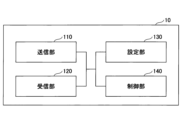
図7は、本発明の実施の形態における基地局10の機能構成の一例を示す図である。図7に示されるように、基地局10は、送信部110と、受信部120と、設定部130と、制御部140とを有する。図7に示される機能構成は一例に過ぎない。本発明の実施の形態に係る動作を実行できるのであれば、機能区分及び機能部の名称はどのようなものでもよい。ネットワークノード30は、基地局10と同様の機能構成を有してもよい。
<
Fig. 7 is a diagram showing an example of a functional configuration of the
送信部110は、端末20側に送信する信号を生成し、当該信号を無線で送信する機能を含む。また、送信部110は、ネットワークノード間メッセージを他のネットワークノードに送信する。受信部120は、端末20から送信された各種の信号を受信し、受信した信号から、例えばより上位のレイヤの情報を取得する機能を含む。また、送信部110は、端末20へNR-PSS、NR-SSS、NR-PBCH、DL/UL制御信号等を送信する機能を有する。また、受信部120は、ネットワークノード間メッセージを他のネットワークノードから受信する。The transmitting
設定部130は、予め設定される設定情報、及び、端末20に送信する各種の設定情報を格納する。設定情報の内容は、例えば、PDUセッションに係る情報等である。The
制御部140は、実施例において説明したように、PDUセッションによる通信に係る制御を行う。また、制御部140は、端末20から受信した無線パラメータに関するUE能力報告に基づいて、端末20との通信を制御する。制御部140における信号送信に関する機能部を送信部110に含め、制御部140における信号受信に関する機能部を受信部120に含めてもよい。As described in the embodiment, the
<端末20>
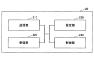
図8は、本発明の実施の形態における端末20の機能構成の一例を示す図である。図8に示されるように、端末20は、送信部210と、受信部220と、設定部230と、制御部240とを有する。図8に示される機能構成は一例に過ぎない。本発明の実施の形態に係る動作を実行できるのであれば、機能区分及び機能部の名称はどのようなものでもよい。
<
Fig. 8 is a diagram showing an example of a functional configuration of the terminal 20 in the embodiment of the present invention. As shown in Fig. 8, the terminal 20 has a transmitting
送信部210は、送信データから送信信号を作成し、当該送信信号を無線で送信する。受信部220は、各種の信号を無線受信し、受信した物理レイヤの信号からより上位のレイヤの信号を取得する。また、受信部220は、基地局10から送信されるNR-PSS、NR-SSS、NR-PBCH、DL/UL/SL制御信号等を受信する機能を有する。また、例えば、送信部210は、D2D通信として、他の端末20に、PSCCH(Physical Sidelink Control Channel)、PSSCH(Physical Sidelink Shared Channel)、PSDCH(Physical Sidelink Discovery Channel)、PSBCH(Physical Sidelink Broadcast Channel)等を送信し、受信部120は、他の端末20から、PSCCH、PSSCH、PSDCH又はPSBCH等を受信する。The
設定部230は、受信部220により基地局10から受信した各種の設定情報を格納する。また、設定部230は、予め設定される設定情報も格納する。設定情報の内容は、例えば、PDUセッションに係る情報等である。The
制御部240は、実施例において説明したように、PDUセッションによる通信に係る制御を行う。制御部240における信号送信に関する機能部を送信部210に含め、制御部240における信号受信に関する機能部を受信部220に含めてもよい。As described in the embodiment, the
(ハードウェア構成)
上記実施形態の説明に用いたブロック図(図7及び図8)は、機能単位のブロックを示している。これらの機能ブロック(構成部)は、ハードウェア及びソフトウェアの少なくとも一方の任意の組み合わせによって実現される。また、各機能ブロックの実現方法は特に限定されない。すなわち、各機能ブロックは、物理的又は論理的に結合した1つの装置を用いて実現されてもよいし、物理的又は論理的に分離した2つ以上の装置を直接的又は間接的に(例えば、有線、無線などを用いて)接続し、これら複数の装置を用いて実現されてもよい。機能ブロックは、上記1つの装置又は上記複数の装置にソフトウェアを組み合わせて実現されてもよい。
(Hardware configuration)
The block diagrams (FIGS. 7 and 8) used in the description of the above embodiments show functional blocks. These functional blocks (components) are realized by any combination of at least one of hardware and software. The method of realizing each functional block is not particularly limited. That is, each functional block may be realized using one device that is physically or logically coupled, or may be realized using two or more devices that are physically or logically separated and directly or indirectly connected (for example, using wires, wirelessly, etc.) and these multiple devices. The functional block may be realized by combining the one device or the multiple devices with software.
機能には、判断、決定、判定、計算、算出、処理、導出、調査、探索、確認、受信、送信、出力、アクセス、解決、選択、選定、確立、比較、想定、期待、見做し、報知(broadcasting)、通知(notifying)、通信(communicating)、転送(forwarding)、構成(configuring)、再構成(reconfiguring)、割り当て(allocating、mapping)、割り振り(assigning)などがあるが、これらに限られない。たとえば、送信を機能させる機能ブロック(構成部)は、送信部(transmitting unit)や送信機(transmitter)と呼称される。いずれも、上述したとおり、実現方法は特に限定されない。 Functions include, but are not limited to, judgement, determination, judgment, calculation, computation, processing, derivation, investigation, search, confirmation, reception, transmission, output, access, resolution, selection, election, establishment, comparison, assumption, expectation, regard, broadcasting, notifying, communicating, forwarding, configuring, reconfiguring, allocating, mapping, and assignment. For example, a functional block (component) that performs the transmission function is called a transmitting unit or transmitter. As mentioned above, there are no particular limitations on the method of realization for either of these.
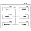
例えば、本開示の一実施の形態における基地局10、端末20等は、本開示の無線通信方法の処理を行うコンピュータとして機能してもよい。図9は、本開示の一実施の形態に係る基地局10及び端末20のハードウェア構成の一例を示す図である。上述の基地局10及び端末20は、物理的には、プロセッサ1001、記憶装置1002、補助記憶装置1003、通信装置1004、入力装置1005、出力装置1006、バス1007などを含むコンピュータ装置として構成されてもよい。For example, the
なお、以下の説明では、「装置」という文言は、回路、デバイス、ユニット等に読み替えることができる。基地局10及び端末20のハードウェア構成は、図に示した各装置を1つ又は複数含むように構成されてもよいし、一部の装置を含まずに構成されてもよい。In the following description, the term "apparatus" may be interpreted as a circuit, device, unit, etc. The hardware configuration of the
基地局10及び端末20における各機能は、プロセッサ1001、記憶装置1002等のハードウェア上に所定のソフトウェア(プログラム)を読み込ませることによって、プロセッサ1001が演算を行い、通信装置1004による通信を制御したり、記憶装置1002及び補助記憶装置1003におけるデータの読み出し及び書き込みの少なくとも一方を制御したりすることによって実現される。Each function in the
プロセッサ1001は、例えば、オペレーティングシステムを動作させてコンピュータ全体を制御する。プロセッサ1001は、周辺装置とのインタフェース、制御装置、演算装置、レジスタ等を含む中央処理装置(CPU:Central Processing Unit)で構成されてもよい。例えば、上述の制御部140、制御部240等は、プロセッサ1001によって実現されてもよい。The
また、プロセッサ1001は、プログラム(プログラムコード)、ソフトウェアモジュール又はデータ等を、補助記憶装置1003及び通信装置1004の少なくとも一方から記憶装置1002に読み出し、これらに従って各種の処理を実行する。プログラムとしては、上述の実施の形態において説明した動作の少なくとも一部をコンピュータに実行させるプログラムが用いられる。例えば、図7に示した基地局10の制御部140は、記憶装置1002に格納され、プロセッサ1001で動作する制御プログラムによって実現されてもよい。また、例えば、図8に示した端末20の制御部240は、記憶装置1002に格納され、プロセッサ1001で動作する制御プログラムによって実現されてもよい。上述の各種処理は、1つのプロセッサ1001によって実行される旨を説明してきたが、2以上のプロセッサ1001により同時又は逐次に実行されてもよい。プロセッサ1001は、1以上のチップによって実装されてもよい。なお、プログラムは、電気通信回線を介してネットワークから送信されてもよい。
The
記憶装置1002は、コンピュータ読み取り可能な記録媒体であり、例えば、ROM(Read Only Memory)、EPROM(Erasable Programmable ROM)、EEPROM(Electrically Erasable Programmable ROM)、RAM(Random Access Memory)等の少なくとも1つによって構成されてもよい。記憶装置1002は、レジスタ、キャッシュ、メインメモリ(主記憶装置)等と呼ばれてもよい。記憶装置1002は、本開示の一実施の形態に係る通信方法を実施するために実行可能なプログラム(プログラムコード)、ソフトウェアモジュール等を保存することができる。The
補助記憶装置1003は、コンピュータ読み取り可能な記録媒体であり、例えば、CD-ROM(Compact Disc ROM)等の光ディスク、ハードディスクドライブ、フレキシブルディスク、光磁気ディスク(例えば、コンパクトディスク、デジタル多用途ディスク、Blu-ray(登録商標)ディスク)、スマートカード、フラッシュメモリ(例えば、カード、スティック、キードライブ)、フロッピー(登録商標)ディスク、磁気ストリップ等の少なくとも1つによって構成されてもよい。上述の記憶媒体は、例えば、記憶装置1002及び補助記憶装置1003の少なくとも一方を含むデータベース、サーバその他の適切な媒体であってもよい。The
通信装置1004は、有線ネットワーク及び無線ネットワークの少なくとも一方を介してコンピュータ間の通信を行うためのハードウェア(送受信デバイス)であり、例えばネットワークデバイス、ネットワークコントローラ、ネットワークカード、通信モジュールなどともいう。通信装置1004は、例えば周波数分割複信(FDD:Frequency Division Duplex)及び時分割複信(TDD:Time Division Duplex)の少なくとも一方を実現するために、高周波スイッチ、デュプレクサ、フィルタ、周波数シンセサイザなどを含んで構成されてもよい。例えば、送受信アンテナ、アンプ部、送受信部、伝送路インタフェース等は、通信装置1004によって実現されてもよい。送受信部は、送信部と受信部とで、物理的に、または論理的に分離された実装がなされてもよい。The
入力装置1005は、外部からの入力を受け付ける入力デバイス(例えば、キーボード、マウス、マイクロフォン、スイッチ、ボタン、センサ等)である。出力装置1006は、外部への出力を実施する出力デバイス(例えば、ディスプレイ、スピーカー、LEDランプ等)である。なお、入力装置1005及び出力装置1006は、一体となった構成(例えば、タッチパネル)であってもよい。The
また、プロセッサ1001及び記憶装置1002等の各装置は、情報を通信するためのバス1007によって接続される。バス1007は、単一のバスを用いて構成されてもよいし、装置間ごとに異なるバスを用いて構成されてもよい。In addition, each device such as the
また、基地局10及び端末20は、マイクロプロセッサ、デジタル信号プロセッサ(DSP:Digital Signal Processor)、ASIC(Application Specific Integrated Circuit)、PLD(Programmable Logic Device)、FPGA(Field Programmable Gate Array)等のハードウェアを含んで構成されてもよく、当該ハードウェアにより、各機能ブロックの一部又は全てが実現されてもよい。例えば、プロセッサ1001は、これらのハードウェアの少なくとも1つを用いて実装されてもよい。In addition, the
(実施の形態のまとめ)
以上、説明したように、本発明の実施の形態によれば、PDU(Protocol Data Unit)セッションを確立するとき、UPF(User Plane Function)及び伝送網事業者を選択し、前記伝送網事業者及び前記伝送網事業者が提供するサービス種別を示す情報をエンコードしてネットワークインスタンスを決定する制御部と、前記ネットワークインスタンスを前記UPFに送信する送信部と、前記UPFから上りリンクに対応する第1のTEID(Tunnel Endpoint Identifier)を受信し、gNB-CU-CP(next generation Node B - Central Unit - Control Plane)から下りリンクに対応する第2のTEIDを受信する受信部とを有し、前記送信部は、データ伝送路において前記UPFとgNB-CU-UP(next generation Node B - Central Unit - User Plane)との間に設置されるトランスポートに、前記第1のTEIDと、前記第2のTEIDと、PLMN(Public Land Mobile Network)に対応するインタフェースを示す情報とを送信して、前記PDUセッションを確立するネットワークノードが提供される。
(Summary of the embodiment)
As described above, according to an embodiment of the present invention, when establishing a PDU (Protocol Data Unit) session, a control unit selects a UPF (User Plane Function) and a transmission network operator, and encodes information indicating the transmission network operator and the service type provided by the transmission network operator to determine a network instance, a transmission unit transmits the network instance to the UPF, and a reception unit receives a first TEID (Tunnel Endpoint Identifier) corresponding to an uplink from the UPF and a second TEID corresponding to a downlink from a gNB-CU-CP (next generation Node B - Central Unit - Control Plane), and the transmission unit transmits the first TEID, the second TEID, and information indicating an interface corresponding to a PLMN (Public Land Mobile Network) to a transport installed between the UPF and the gNB-CU-UP (next generation Node B - Central Unit - User Plane) in a data transmission path to establish the PDU session.
上記の構成により、PLMNは、トラヒック特性に応じ呼毎に他社伝送路を選択できる。伝送網事業者は、複数PLMNからの呼毎の伝送サービス提供要求に応えることができる。すなわち、無線通信システムにおいて、ユーザデータ伝送路の使用効率を向上させることができる。 With the above configuration, a PLMN can select another company's transmission path for each call depending on the traffic characteristics. Transmission network operators can respond to requests for transmission services for each call from multiple PLMNs. In other words, the utilization efficiency of user data transmission paths can be improved in wireless communication systems.
前記PLMNに対応するインタフェースを示す情報は、PFCP(Packet Forwarding Control Protocol)セッション確立要求における、下りリンクのソースインタフェース及び上りリンクのデスティネーションインタフェースに対応する前記PLMNにおけるUPFを示す情報と、下りリンクのデスティネーションインタフェース及び上りリンクのソースインタフェースに対応する前記PLMNにおけるgNB-CU-UPを示す情報とを含んでもよい。当該構成により、伝送網事業者は、複数PLMNからの呼毎の伝送サービス提供要求に応えることができる。The information indicating the interface corresponding to the PLMN may include information indicating a UPF in the PLMN corresponding to a downlink source interface and an uplink destination interface in a PFCP (Packet Forwarding Control Protocol) session establishment request, and information indicating a gNB-CU-UP in the PLMN corresponding to a downlink destination interface and an uplink source interface. With this configuration, a transmission network operator can respond to transmission service provision requests for each call from multiple PLMNs.
前記受信部は、下りリンクに対応する第3のTEID及び上りリンクに対応する第4のTEIDを、前記トランスポートから受信してもよい。当該構成により、伝送網事業者は、複数PLMNからの呼毎の伝送サービス提供要求に応えることができる。The receiver may receive a third TEID corresponding to a downlink and a fourth TEID corresponding to an uplink from the transport. This configuration enables a transmission network operator to respond to transmission service requests for each call from multiple PLMNs.
前記送信部は、前記第3のTEIDを前記UPFに送信してもよい。当該構成により、伝送網事業者は、複数PLMNからの呼毎の伝送サービス提供要求に応えることができる。The transmitting unit may transmit the third TEID to the UPF. With this configuration, a transmission network operator can respond to transmission service provision requests for each call from multiple PLMNs.
前記送信部は、前記第4のTEID及び前記ネットワークインスタンスをAMF(Access and Mobility Management Function)に送信してもよい。上記の構成により、PLMNは、トラヒック特性に応じ呼毎に他社伝送路を選択できる。伝送網事業者は、複数PLMNからの呼毎の伝送サービス提供要求に応えることができる。 The transmitting unit may transmit the fourth TEID and the network instance to an AMF (Access and Mobility Management Function). With the above configuration, a PLMN can select another company's transmission path for each call depending on traffic characteristics. A transmission network operator can respond to requests for transmission services for each call from multiple PLMNs.
また、本発明の実施の形態によれば、PDU(Protocol Data Unit)セッションを確立するとき、UPF(User Plane Function)及び伝送網事業者を選択し、前記伝送網事業者及び前記伝送網事業者が提供するサービス種別を示す情報をエンコードしてネットワークインスタンスを決定する制御手順と、前記ネットワークインスタンスを前記UPFに送信する送信手順と、前記UPFから上りリンクに対応する第1のTEID(Tunnel Endpoint Identifier)を受信し、gNB-CU-CP(next generation Node B - Central Unit - Control Plane)から下りリンクに対応する第2のTEIDを受信する受信手順と、データ伝送路において前記UPFとgNB-CU-UP(next generation Node B - Central Unit - User Plane)との間に設置されるトランスポートに、前記第1のTEIDと、前記第2のTEIDと、PLMN(Public Land Mobile Network)に対応するインタフェースを示す情報とを送信して、前記PDUセッションを確立する手順とをネットワークノードが実行する通信方法が提供される。 In addition, according to an embodiment of the present invention, a communication method is provided in which, when establishing a PDU (Protocol Data Unit) session, a network node executes the following steps: a control procedure for selecting a UPF (User Plane Function) and a transmission network operator, and encoding information indicating the transmission network operator and the service type provided by the transmission network operator to determine a network instance; a transmission procedure for transmitting the network instance to the UPF; a reception procedure for receiving a first TEID (Tunnel Endpoint Identifier) corresponding to the uplink from the UPF and receiving a second TEID corresponding to the downlink from a gNB-CU-CP (next generation Node B - Central Unit - Control Plane); and a procedure for transmitting the first TEID, the second TEID, and information indicating an interface corresponding to a PLMN (Public Land Mobile Network) to a transport installed between the UPF and the gNB-CU-UP (next generation Node B - Central Unit - User Plane) in a data transmission path to establish the PDU session.
上記の構成により、PLMNは、トラヒック特性に応じ呼毎に他社伝送路を選択できる。伝送網事業者は、複数PLMNからの呼毎の伝送サービス提供要求に応えることができる。すなわち、無線通信システムにおいて、ユーザデータ伝送路の使用効率を向上させることができる。 With the above configuration, a PLMN can select another company's transmission path for each call depending on the traffic characteristics. Transmission network operators can respond to requests for transmission services for each call from multiple PLMNs. In other words, the utilization efficiency of user data transmission paths can be improved in wireless communication systems.
また、本発明の実施の形態によれば、SMF(Session Management Function)から上りリンクに対応する第1のTEID(Tunnel Endpoint Identifier)と、下りリンクに対応する第2のTEIDと、PLMN(Public Land Mobile Network)に対応するインタフェースを示す情報とを受信する受信部と、前記第1のTEID、前記第2のTEID及び前記PLMNに対応するインタフェースを示す情報に基づいて、UPF(User Plane Function)とgNB-CU-UP(next generation Node B - Central Unit - User Plane)との間にデータ伝送路を設定する制御部とを有し、前記第1のTEIDは、前記UPFから前記SMFに送信され、前記第2のTEIDは、gNB-CU-CP(next generation Node B - Central Unit - Control Plane)から前記SMFに送信されるトランスポートが提供される。 According to an embodiment of the present invention, the present invention includes a receiving unit that receives from an SMF (Session Management Function) a first TEID (Tunnel Endpoint Identifier) corresponding to an uplink, a second TEID corresponding to a downlink, and information indicating an interface corresponding to a PLMN (Public Land Mobile Network), and a control unit that sets a data transmission path between a UPF (User Plane Function) and a gNB-CU-UP (next generation Node B - Central Unit - User Plane) based on the first TEID, the second TEID, and the information indicating the interface corresponding to the PLMN, and a transport is provided in which the first TEID is transmitted from the UPF to the SMF and the second TEID is transmitted from the gNB-CU-CP (next generation Node B - Central Unit - Control Plane) to the SMF.
上記の構成により、PLMNは、トラヒック特性に応じ呼毎に他社伝送路を選択できる。伝送網事業者は、複数PLMNからの呼毎の伝送サービス提供要求に応えることができる。すなわち、無線通信システムにおいて、ユーザデータ伝送路の使用効率を向上させることができる。 With the above configuration, a PLMN can select another company's transmission path for each call depending on the traffic characteristics. Transmission network operators can respond to requests for transmission services for each call from multiple PLMNs. In other words, the utilization efficiency of user data transmission paths can be improved in wireless communication systems.
また、本発明の実施の形態によれば、PDU(Protocol Data Unit)セッションを確立するとき、gNB-CU-UP(next generation Node B - Central Unit - User Plane)及び伝送網事業者を選択し、前記伝送網事業者及び前記伝送網事業者が提供するサービス種別を示す情報をエンコードしてネットワークインスタンスを決定する制御部と、前記ネットワークインスタンスを前記gNB-CU-UPに送信する送信部と、前記gNB-CU-UPから上りリンクに対応する第5のTEID(Tunnel Endpoint Identifier)を受信し、gNB-DU(next generation Node B - Distributed Unit)から下りリンクに対応する第6のTEIDを受信する受信部とを有し、前記送信部は、データ伝送路において前記gNB-CU-UPとgNB-DUの間に設置されるトランスポートに、前記第5のTEIDと、前記第6のTEIDと、PLMN(Public Land Mobile Network)に対応するインタフェースを示す情報とを送信して、前記PDUセッションを確立するネットワークノードが提供される。 Furthermore, according to an embodiment of the present invention, a network node is provided that, when establishing a PDU (Protocol Data Unit) session, has a control unit that selects a gNB-CU-UP (next generation Node B - Central Unit - User Plane) and a transmission network operator, and encodes information indicating the transmission network operator and the service type provided by the transmission network operator to determine a network instance, a transmission unit that transmits the network instance to the gNB-CU-UP, and a reception unit that receives a fifth TEID (Tunnel Endpoint Identifier) corresponding to the uplink from the gNB-CU-UP and a sixth TEID corresponding to the downlink from the gNB-DU (next generation Node B - Distributed Unit), wherein the transmission unit transmits the fifth TEID, the sixth TEID, and information indicating an interface corresponding to a PLMN (Public Land Mobile Network) to a transport installed between the gNB-CU-UP and the gNB-DU in a data transmission path, thereby establishing the PDU session.
上記の構成により、PLMNは、トラヒック特性に応じ呼毎に他社伝送路を選択できる。伝送網事業者は、複数PLMNからの呼毎の伝送サービス提供要求に応えることができる。すなわち、無線通信システムにおいて、ユーザデータ伝送路の使用効率を向上させることができる。 With the above configuration, a PLMN can select another company's transmission path for each call depending on the traffic characteristics. Transmission network operators can respond to requests for transmission services for each call from multiple PLMNs. In other words, the utilization efficiency of user data transmission paths can be improved in wireless communication systems.
前記PLMNに対応するインタフェースを示す情報は、PFCP(Packet Forwarding Control Protocol)セッション確立要求における、下りリンクのソースインタフェース及び上りリンクのデスティネーションインタフェースに対応する前記PLMNにおけるgNB-CU-UPを示す情報と、下りリンクのデスティネーションインタフェース及び上りリンクのソースインタフェースに対応する前記PLMNにおけるgNB-DUを示す情報とを含んでもよい。当該構成により、伝送網事業者は、複数PLMNからの呼毎の伝送サービス提供要求に応えることができる。 The information indicating the interface corresponding to the PLMN may include information indicating a gNB-CU-UP in the PLMN corresponding to a downlink source interface and an uplink destination interface in a PFCP (Packet Forwarding Control Protocol) session establishment request, and information indicating a gNB-DU in the PLMN corresponding to a downlink destination interface and an uplink source interface. With this configuration, a transmission network operator can respond to transmission service provision requests for each call from multiple PLMNs.
前記受信部は、下りリンクに対応する第7のTEID及び上りリンクに対応する第8のTEIDを、前記トランスポートから受信してもよい。当該構成により、伝送網事業者は、複数PLMNからの呼毎の伝送サービス提供要求に応えることができる。The receiver may receive from the transport a seventh TEID corresponding to the downlink and an eighth TEID corresponding to the uplink. With this configuration, the transmission network operator can respond to transmission service provision requests for each call from multiple PLMNs.
前記送信部は、前記第7のTEIDを前記gNB-CU-UPに送信してもよい。当該構成により、伝送網事業者は、複数PLMNからの呼毎の伝送サービス提供要求に応えることができる。The transmitting unit may transmit the seventh TEID to the gNB-CU-UP. With this configuration, a transmission network operator can respond to transmission service provision requests for each call from multiple PLMNs.
前記送信部は、前記第8のTEIDを前記gNB-DUに送信してもよい。当該構成により、伝送網事業者は、複数PLMNからの呼毎の伝送サービス提供要求に応えることができる。The transmitting unit may transmit the eighth TEID to the gNB-DU. With this configuration, a transmission network operator can respond to transmission service provision requests for each call from multiple PLMNs.
また、本発明の実施の形態によれば、PDU(Protocol Data Unit)セッションを確立するとき、gNB-CU-UP(next generation Node B - Central Unit - User Plane)及び伝送網事業者を選択し、前記伝送網事業者及び前記伝送網事業者が提供するサービス種別を示す情報をエンコードしてネットワークインスタンスを決定する制御手順と、前記ネットワークインスタンスを前記gNB-CU-UPに送信する送信手順と、前記gNB-CU-UPから上りリンクに対応する第5のTEID(Tunnel Endpoint Identifier)を受信し、gNB-DU(next generation Node B - Distributed Unit)から下りリンクに対応する第6のTEIDを受信する受信手順と、データ伝送路において前記gNB-CU-UPとgNB-DUとの間に設置されるトランスポートに、前記第5のTEIDと、前記第6のTEIDと、PLMN(Public Land Mobile Network)に対応するインタフェースを示す情報とを送信して、前記PDUセッションを確立する手順とをネットワークノードが実行する通信方法が提供される。 In addition, according to an embodiment of the present invention, a communication method is provided in which, when establishing a PDU (Protocol Data Unit) session, a network node executes the following procedures: a control procedure for selecting a gNB-CU-UP (next generation Node B - Central Unit - User Plane) and a transmission network operator, and encoding information indicating the transmission network operator and the service type provided by the transmission network operator to determine a network instance; a transmission procedure for transmitting the network instance to the gNB-CU-UP; a reception procedure for receiving a fifth TEID (Tunnel Endpoint Identifier) corresponding to the uplink from the gNB-CU-UP and receiving a sixth TEID corresponding to the downlink from the gNB-DU (next generation Node B - Distributed Unit); and a procedure for transmitting the fifth TEID, the sixth TEID, and information indicating an interface corresponding to a PLMN (Public Land Mobile Network) to a transport installed between the gNB-CU-UP and the gNB-DU in a data transmission path to establish the PDU session.
上記の構成により、PLMNは、トラヒック特性に応じ呼毎に他社伝送路を選択できる。伝送網事業者は、複数PLMNからの呼毎の伝送サービス提供要求に応えることができる。すなわち、無線通信システムにおいて、ユーザデータ伝送路の使用効率を向上させることができる。 With the above configuration, a PLMN can select another company's transmission path for each call depending on the traffic characteristics. Transmission network operators can respond to requests for transmission services for each call from multiple PLMNs. In other words, the utilization efficiency of user data transmission paths can be improved in wireless communication systems.
また、本発明の実施の形態によれば、gNB-CU-CP(next generation Node B - Central Unit - Control Plane)から上りリンクに対応する第5のTEID(Tunnel Endpoint Identifier)と、下りリンクに対応する第6のTEIDと、PLMN(Public Land Mobile Network)に対応するインタフェースを示す情報とを受信する受信部と、前記第5のTEID、前記第6のTEID及び前記PLMNに対応するインタフェースを示す情報に基づいて、gNB-CU-UP(next generation Node B - Central Unit - User Plane)とgNB-DU(next generation Node B - Distributed Unit)との間にデータ伝送路を設定する制御部とを有し、前記第5のTEIDは、前記gNB-CU-UPから前記gNB-CU-CPに送信され、前記第6のTEIDは、前記gNB-DUから前記gNB-CU-CPに送信されるトランスポートが提供される。 Furthermore, according to an embodiment of the present invention, a receiving unit receives a fifth TEID (Tunnel Endpoint Identifier) corresponding to the uplink from a gNB-CU-CP (next generation Node B - Central Unit - Control Plane), a sixth TEID corresponding to the downlink, and information indicating an interface corresponding to a PLMN (Public Land Mobile Network), and a control unit sets up a data transmission path between a gNB-CU-UP (next generation Node B - Central Unit - User Plane) and a gNB-DU (next generation Node B - Distributed Unit) based on the fifth TEID, the sixth TEID, and the information indicating the interface corresponding to the PLMN, and transport is provided in which the fifth TEID is transmitted from the gNB-CU-UP to the gNB-CU-CP and the sixth TEID is transmitted from the gNB-DU to the gNB-CU-CP.
上記の構成により、PLMNは、トラヒック特性に応じ呼毎に他社伝送路を選択できる。伝送網事業者は、複数PLMNからの呼毎の伝送サービス提供要求に応えることができる。すなわち、無線通信システムにおいて、ユーザデータ伝送路の使用効率を向上させることができる。 With the above configuration, a PLMN can select another company's transmission path for each call depending on the traffic characteristics. Transmission network operators can respond to requests for transmission services for each call from multiple PLMNs. In other words, the utilization efficiency of user data transmission paths can be improved in wireless communication systems.
(実施形態の補足)
以上、本発明の実施の形態を説明してきたが、開示される発明はそのような実施形態に限定されず、当業者は様々な変形例、修正例、代替例、置換例等を理解するであろう。発明の理解を促すため具体的な数値例を用いて説明がなされたが、特に断りのない限り、それらの数値は単なる一例に過ぎず適切な如何なる値が使用されてもよい。上記の説明における項目の区分けは本発明に本質的ではなく、2以上の項目に記載された事項が必要に応じて組み合わせて使用されてよいし、ある項目に記載された事項が、別の項目に記載された事項に(矛盾しない限り)適用されてよい。機能ブロック図における機能部又は処理部の境界は必ずしも物理的な部品の境界に対応するとは限らない。複数の機能部の動作が物理的には1つの部品で行われてもよいし、あるいは1つの機能部の動作が物理的には複数の部品により行われてもよい。実施の形態で述べた処理手順については、矛盾の無い限り処理の順序を入れ替えてもよい。処理説明の便宜上、ネットワークノード30及び端末20は機能的なブロック図を用いて説明されたが、そのような装置はハードウェアで、ソフトウェアで又はそれらの組み合わせで実現されてもよい。本発明の実施の形態に従ってネットワークノード30が有するプロセッサにより動作するソフトウェア及び本発明の実施の形態に従って端末20が有するプロセッサにより動作するソフトウェアはそれぞれ、ランダムアクセスメモリ(RAM)、フラッシュメモリ、読み取り専用メモリ(ROM)、EPROM、EEPROM、レジスタ、ハードディスク(HDD)、リムーバブルディスク、CD-ROM、データベース、サーバその他の適切な如何なる記憶媒体に保存されてもよい。
(Supplementary description of the embodiment)
Although the embodiment of the present invention has been described above, the disclosed invention is not limited to such an embodiment, and those skilled in the art will understand various modifications, modifications, alternatives, replacements, and the like. Although the description has been given using specific numerical examples to facilitate understanding of the invention, unless otherwise specified, those numerical values are merely examples and any appropriate value may be used. The division of items in the above description is not essential to the present invention, and matters described in two or more items may be used in combination as necessary, and matters described in one item may be applied to matters described in another item (as long as there is no contradiction). The boundaries of functional units or processing units in the functional block diagram do not necessarily correspond to the boundaries of physical parts. The operations of multiple functional units may be physically performed by one part, or the operations of one functional unit may be physically performed by multiple parts. The order of the processing procedures described in the embodiment may be changed as long as there is no contradiction. For convenience of the processing description, the network node 30 and the terminal 20 have been described using functional block diagrams, but such devices may be realized by hardware, software, or a combination thereof. The software operated by the processor of the network node 30 in accordance with an embodiment of the present invention and the software operated by the processor of the terminal 20 in accordance with an embodiment of the present invention may each be stored in any suitable storage medium, such as random access memory (RAM), flash memory, read only memory (ROM), EPROM, EEPROM, register, hard disk (HDD), removable disk, CD-ROM, database, server or the like.
また、情報の通知は、本開示で説明した態様/実施形態に限られず、他の方法を用いて行われてもよい。例えば、情報の通知は、物理レイヤシグナリング(例えば、DCI(Downlink Control Information)、UCI(Uplink Control Information))、上位レイヤシグナリング(例えば、RRC(Radio Resource Control)シグナリング、MAC(Medium Access Control)シグナリング、報知情報(MIB(Master Information Block)、SIB(System Information Block))、その他の信号又はこれらの組み合わせによって実施されてもよい。また、RRCシグナリングは、RRCメッセージと呼ばれてもよく、例えば、RRC接続セットアップ(RRC Connection Setup)メッセージ、RRC接続再構成(RRC Connection Reconfiguration)メッセージ等であってもよい。In addition, the notification of information is not limited to the aspects/embodiments described in the present disclosure, and may be performed using other methods. For example, the notification of information may be performed by physical layer signaling (e.g., DCI (Downlink Control Information), UCI (Uplink Control Information)), higher layer signaling (e.g., RRC (Radio Resource Control) signaling, MAC (Medium Access Control) signaling, broadcast information (MIB (Master Information Block), SIB (System Information Block)), other signals, or combinations thereof. In addition, the RRC signaling may be called an RRC message, and may be, for example, an RRC Connection Setup message, an RRC Connection Reconfiguration message, etc.
本開示において説明した各態様/実施形態は、LTE(Long Term Evolution)、LTE-A(LTE-Advanced)、SUPER 3G、IMT-Advanced、4G(4th generation mobile communication system)、5G(5th generation mobile communication system)、FRA(Future Radio Access)、NR(new Radio)、W-CDMA(登録商標)、GSM(登録商標)、CDMA2000、UMB(Ultra Mobile Broadband)、IEEE 802.11(Wi-Fi(登録商標))、IEEE 802.16(WiMAX(登録商標))、IEEE 802.20、UWB(Ultra-WideBand)、Bluetooth(登録商標)、その他の適切なシステムを利用するシステム及びこれらに基づいて拡張された次世代システムの少なくとも一つに適用されてもよい。また、複数のシステムが組み合わされて(例えば、LTE及びLTE-Aの少なくとも一方と5Gとの組み合わせ等)適用されてもよい。Each aspect/embodiment described in this disclosure may be applied to at least one of systems utilizing LTE (Long Term Evolution), LTE-Advanced (LTE-A), SUPER 3G, IMT-Advanced, 4G (4th generation mobile communication system), 5G (5th generation mobile communication system), FRA (Future Radio Access), NR (new Radio), W-CDMA (registered trademark), GSM (registered trademark), CDMA2000, UMB (Ultra Mobile Broadband), IEEE 802.11 (Wi-Fi (registered trademark)), IEEE 802.16 (WiMAX (registered trademark)), IEEE 802.20, UWB (Ultra-WideBand), Bluetooth (registered trademark), or other suitable systems, and next generation systems enhanced based on these. In addition, multiple systems may be applied in combination (for example, a combination of at least one of LTE and LTE-A with 5G, etc.).
本明細書で説明した各態様/実施形態の処理手順、シーケンス、フローチャート等は、矛盾の無い限り、順序を入れ替えてもよい。例えば、本開示において説明した方法については、例示的な順序を用いて様々なステップの要素を提示しており、提示した特定の順序に限定されない。The processing steps, sequences, flow charts, etc. of each aspect/embodiment described herein may be reordered unless inconsistent. For example, the methods described in this disclosure present elements of various steps using an example order and are not limited to the particular order presented.
本明細書においてネットワークノード30によって行われるとした特定動作は、場合によってはその上位ノード(upper node)によって行われることもある。ネットワークノード30を有する1つ又は複数のネットワークノード(network nodes)からなるネットワークにおいて、端末20との通信のために行われる様々な動作は、ネットワークノード30及びネットワークノード30以外の他のネットワークノード(例えば、MME又はS-GW等が考えられるが、これらに限られない)の少なくとも1つによって行われ得ることは明らかである。上記においてネットワークノード30以外の他のネットワークノードが1つである場合を例示したが、他のネットワークノードは、複数の他のネットワークノードの組み合わせ(例えば、MME及びS-GW)であってもよい。In this specification, a particular operation that is described as being performed by the network node 30 may in some cases be performed by its upper node. In a network consisting of one or more network nodes having the network node 30, it is clear that various operations performed for communication with the terminal 20 may be performed by the network node 30 and at least one of other network nodes other than the network node 30 (e.g., MME or S-GW, etc., but are not limited to these). Although the above example shows a case where there is one other network node other than the network node 30, the other network node may be a combination of multiple other network nodes (e.g., MME and S-GW).
本開示において説明した情報又は信号等は、上位レイヤ(又は下位レイヤ)から下位レイヤ(又は上位レイヤ)へ出力され得る。複数のネットワークノードを介して入出力されてもよい。The information or signals described in this disclosure may be output from a higher layer (or a lower layer) to a lower layer (or a higher layer). They may be input and output via multiple network nodes.
入出力された情報等は特定の場所(例えば、メモリ)に保存されてもよいし、管理テーブルを用いて管理してもよい。入出力される情報等は、上書き、更新、又は追記され得る。出力された情報等は削除されてもよい。入力された情報等は他の装置へ送信されてもよい。 The input and output information, etc. may be stored in a specific location (e.g., memory) or may be managed using a management table. The input and output information, etc. may be overwritten, updated, or added to. The output information, etc. may be deleted. The input information, etc. may be transmitted to another device.
本開示における判定は、1ビットで表される値(0か1か)によって行われてもよいし、真偽値(Boolean:true又はfalse)によって行われてもよいし、数値の比較(例えば、所定の値との比較)によって行われてもよい。 In the present disclosure, the determination may be made based on a value represented by one bit (0 or 1), a Boolean (true or false) value, or a comparison of numerical values (e.g., comparison with a predetermined value).
ソフトウェアは、ソフトウェア、ファームウェア、ミドルウェア、マイクロコード、ハードウェア記述言語と呼ばれるか、他の名称で呼ばれるかを問わず、命令、命令セット、コード、コードセグメント、プログラムコード、プログラム、サブプログラム、ソフトウェアモジュール、アプリケーション、ソフトウェアアプリケーション、ソフトウェアパッケージ、ルーチン、サブルーチン、オブジェクト、実行可能ファイル、実行スレッド、手順、機能などを意味するよう広く解釈されるべきである。 Software shall be construed broadly to mean instructions, instruction sets, code, code segments, program code, programs, subprograms, software modules, applications, software applications, software packages, routines, subroutines, objects, executable files, threads of execution, procedures, functions, etc., whether referred to as software, firmware, middleware, microcode, hardware description language, or otherwise.
また、ソフトウェア、命令、情報などは、伝送媒体を介して送受信されてもよい。例えば、ソフトウェアが、有線技術(同軸ケーブル、光ファイバケーブル、ツイストペア、デジタル加入者回線(DSL:Digital Subscriber Line)など)及び無線技術(赤外線、マイクロ波など)の少なくとも一方を使用してウェブサイト、サーバ、又は他のリモートソースから送信される場合、これらの有線技術及び無線技術の少なくとも一方は、伝送媒体の定義内に含まれる。Additionally, software, instructions, information, etc. may be transmitted and received via a transmission medium. For example, if the software is transmitted from a website, server, or other remote source using wired technologies (such as coaxial cable, fiber optic cable, twisted pair, Digital Subscriber Line (DSL)), and/or wireless technologies (such as infrared, microwave), then these wired and/or wireless technologies are included within the definition of a transmission medium.
本開示において説明した情報、信号などは、様々な異なる技術のいずれかを使用して表されてもよい。例えば、上記の説明全体に渡って言及され得るデータ、命令、コマンド、情報、信号、ビット、シンボル、チップなどは、電圧、電流、電磁波、磁界若しくは磁性粒子、光場若しくは光子、又はこれらの任意の組み合わせによって表されてもよい。The information, signals, etc. described in this disclosure may be represented using any of a variety of different technologies. For example, data, instructions, commands, information, signals, bits, symbols, chips, etc. that may be referred to throughout the above description may be represented by voltages, currents, electromagnetic waves, magnetic fields or magnetic particles, optical fields or photons, or any combination thereof.
なお、本開示において説明した用語及び本開示の理解に必要な用語については、同一の又は類似する意味を有する用語と置き換えてもよい。例えば、チャネル及びシンボルの少なくとも一方は信号(シグナリング)であってもよい。また、信号はメッセージであってもよい。また、コンポーネントキャリア(CC:Component Carrier)は、キャリア周波数、セル、周波数キャリアなどと呼ばれてもよい。 Note that the terms described in this disclosure and the terms necessary for understanding this disclosure may be replaced with terms having the same or similar meanings. For example, at least one of the channel and the symbol may be a signal (signaling). Also, the signal may be a message. Also, a component carrier (CC) may be called a carrier frequency, a cell, a frequency carrier, etc.
本開示において使用する「システム」及び「ネットワーク」という用語は、互換的に使用される。 As used in this disclosure, the terms "system" and "network" are used interchangeably.
また、本開示において説明した情報、パラメータなどは、絶対値を用いて表されてもよいし、所定の値からの相対値を用いて表されてもよいし、対応する別の情報を用いて表されてもよい。例えば、無線リソースはインデックスによって指示されるものであってもよい。 In addition, the information, parameters, etc. described in this disclosure may be represented using absolute values, may be represented using relative values from a predetermined value, or may be represented using other corresponding information. For example, radio resources may be indicated by an index.
上述したパラメータに使用する名称はいかなる点においても限定的な名称ではない。さらに、これらのパラメータを使用する数式等は、本開示で明示的に開示したものと異なる場合もある。様々なチャネル(例えば、PUCCH、PDCCHなど)及び情報要素は、あらゆる好適な名称によって識別できるので、これらの様々なチャネル及び情報要素に割り当てている様々な名称は、いかなる点においても限定的な名称ではない。The names used for the above-mentioned parameters are not limiting in any way. Moreover, the formulas etc. using these parameters may differ from those explicitly disclosed in this disclosure. The various channels (e.g., PUCCH, PDCCH, etc.) and information elements may be identified by any suitable names, and therefore the various names assigned to these various channels and information elements are not limiting in any way.
本開示においては、「基地局(BS:Base Station)」、「無線基地局」、「基地局装置」、「固定局(fixed station)」、「NodeB」、「eNodeB(eNB)」、「gNodeB(gNB)」、「アクセスポイント(access point)」、「送信ポイント(transmission point)」、「受信ポイント(reception point)、「送受信ポイント(transmission/reception point)」、「セル」、「セクタ」、「セルグループ」、「キャリア」、「コンポーネントキャリア」などの用語は、互換的に使用され得る。基地局は、マクロセル、スモールセル、フェムトセル、ピコセルなどの用語で呼ばれる場合もある。In this disclosure, terms such as "base station (BS)", "radio base station", "base station device", "fixed station", "NodeB", "eNodeB (eNB)", "gNodeB (gNB)", "access point", "transmission point", "reception point", "transmission/reception point", "cell", "sector", "cell group", "carrier", and "component carrier" may be used interchangeably. A base station may also be referred to by terms such as macrocell, small cell, femtocell, and picocell.
基地局は、1つ又は複数(例えば、3つ)のセルを収容することができる。基地局が複数のセルを収容する場合、基地局のカバレッジエリア全体は複数のより小さいエリアに区分でき、各々のより小さいエリアは、基地局サブシステム(例えば、屋内用の小型基地局(RRH:Remote Radio Head)によって通信サービスを提供することもできる。「セル」又は「セクタ」という用語は、このカバレッジにおいて通信サービスを行う基地局及び基地局サブシステムの少なくとも一方のカバレッジエリアの一部又は全体を指す。A base station can accommodate one or more (e.g., three) cells. When a base station accommodates multiple cells, the entire coverage area of the base station can be divided into multiple smaller areas, and each smaller area can also provide communication services by a base station subsystem (e.g., a small indoor base station (RRH: Remote Radio Head). The term "cell" or "sector" refers to a part or the entire coverage area of at least one of the base station and base station subsystem that provides communication services in this coverage.
本開示においては、「移動局(MS:Mobile Station)」、「ユーザ端末(user terminal)」、「ユーザ装置(UE:User Equipment)」、「端末」などの用語は、互換的に使用され得る。In this disclosure, terms such as "Mobile Station (MS)," "user terminal," "User Equipment (UE)," and "terminal" may be used interchangeably.
移動局は、当業者によって、加入者局、モバイルユニット、加入者ユニット、ワイヤレスユニット、リモートユニット、モバイルデバイス、ワイヤレスデバイス、ワイヤレス通信デバイス、リモートデバイス、モバイル加入者局、アクセス端末、モバイル端末、ワイヤレス端末、リモート端末、ハンドセット、ユーザエージェント、モバイルクライアント、クライアント、又はいくつかの他の適切な用語で呼ばれる場合もある。A mobile station may also be referred to by those skilled in the art as a subscriber station, mobile unit, subscriber unit, wireless unit, remote unit, mobile device, wireless device, wireless communication device, remote device, mobile subscriber station, access terminal, mobile terminal, wireless terminal, remote terminal, handset, user agent, mobile client, client, or some other suitable terminology.
基地局及び移動局の少なくとも一方は、送信装置、受信装置、通信装置などと呼ばれてもよい。なお、基地局及び移動局の少なくとも一方は、移動体に搭載されたデバイス、移動体自体などであってもよい。当該移動体は、乗り物(例えば、車、飛行機など)であってもよいし、無人で動く移動体(例えば、ドローン、自動運転車など)であってもよいし、ロボット(有人型又は無人型)であってもよい。なお、基地局及び移動局の少なくとも一方は、必ずしも通信動作時に移動しない装置も含む。例えば、基地局及び移動局の少なくとも一方は、センサなどのIoT(Internet of Things)機器であってもよい。At least one of the base station and the mobile station may be called a transmitting device, a receiving device, a communication device, etc. At least one of the base station and the mobile station may be a device mounted on a moving body, the moving body itself, etc. The moving body may be a vehicle (e.g., a car, an airplane, etc.), an unmanned moving body (e.g., a drone, an autonomous vehicle, etc.), or a robot (manned or unmanned). At least one of the base station and the mobile station may include a device that does not necessarily move during communication operation. For example, at least one of the base station and the mobile station may be an IoT (Internet of Things) device such as a sensor.
また、本開示における基地局は、ユーザ端末で読み替えてもよい。例えば、基地局及びユーザ端末間の通信を、複数の端末20間の通信(例えば、D2D(Device-to-Device)、V2X(Vehicle-to-Everything)などと呼ばれてもよい)に置き換えた構成について、本開示の各態様/実施形態を適用してもよい。この場合、上述のネットワークノード30が有する機能を端末20が有する構成としてもよい。また、「上り」及び「下り」などの文言は、端末間通信に対応する文言(例えば、「サイド(side)」)で読み替えられてもよい。例えば、上りチャネル、下りチャネルなどは、サイドチャネルで読み替えられてもよい。 In addition, the base station in the present disclosure may be read as a user terminal. For example, each aspect/embodiment of the present disclosure may be applied to a configuration in which communication between a base station and a user terminal is replaced with communication between multiple terminals 20 (which may be called, for example, D2D (Device-to-Device), V2X (Vehicle-to-Everything), etc.). In this case, the terminal 20 may be configured to have the functions possessed by the above-mentioned network node 30. Furthermore, terms such as "uplink" and "downlink" may be read as terms corresponding to terminal-to-terminal communication (for example, "side"). For example, the uplink channel, downlink channel, etc. may be read as a side channel.
同様に、本開示におけるユーザ端末は、基地局で読み替えてもよい。この場合、上述のユーザ端末が有する機能を基地局が有する構成としてもよい。Similarly, the user terminal in this disclosure may be interpreted as a base station. In this case, the base station may be configured to have the functions of the user terminal described above.
本開示で使用する「判断(determining)」、「決定(determining)」という用語は、多種多様な動作を包含する場合がある。「判断」、「決定」は、例えば、判定(judging)、計算(calculating)、算出(computing)、処理(processing)、導出(deriving)、調査(investigating)、探索(looking up、search、inquiry)(例えば、テーブル、データベース又は別のデータ構造での探索)、確認(ascertaining)した事を「判断」「決定」したとみなす事などを含み得る。また、「判断」、「決定」は、受信(receiving)(例えば、情報を受信すること)、送信(transmitting)(例えば、情報を送信すること)、入力(input)、出力(output)、アクセス(accessing)(例えば、メモリ中のデータにアクセスすること)した事を「判断」「決定」したとみなす事などを含み得る。また、「判断」、「決定」は、解決(resolving)、選択(selecting)、選定(choosing)、確立(establishing)、比較(comparing)などした事を「判断」「決定」したとみなす事を含み得る。つまり、「判断」「決定」は、何らかの動作を「判断」「決定」したとみなす事を含み得る。また、「判断(決定)」は、「想定する(assuming)」、「期待する(expecting)」、「みなす(considering)」などで読み替えられてもよい。As used in this disclosure, the terms "determining" and "determining" may encompass a wide variety of actions. "Determining" and "determining" may include, for example, judging, calculating, computing, processing, deriving, investigating, looking up, searching, inquiring (e.g., searching in a table, database, or other data structure), ascertaining, and the like. "Determining" and "determining" may also include receiving (e.g., receiving information), transmitting (e.g., sending information), input, output, accessing (e.g., accessing data in memory), and the like. In addition, "judgment" and "decision" can include considering resolving, selecting, choosing, establishing, comparing, etc., to be a "judgment" or "decision." In other words, "judgment" and "decision" can include considering some action to be a "judgment" or "decision." Furthermore, "judgment (decision)" can be interpreted as "assuming," "expecting," "considering," etc.
「接続された(connected)」、「結合された(coupled)」という用語、又はこれらのあらゆる変形は、2又はそれ以上の要素間の直接的又は間接的なあらゆる接続又は結合を意味し、互いに「接続」又は「結合」された2つの要素間に1又はそれ以上の中間要素が存在することを含むことができる。要素間の結合又は接続は、物理的なものであっても、論理的なものであっても、或いはこれらの組み合わせであってもよい。例えば、「接続」は「アクセス」で読み替えられてもよい。本開示で使用する場合、2つの要素は、1又はそれ以上の電線、ケーブル及びプリント電気接続の少なくとも一つを用いて、並びにいくつかの非限定的かつ非包括的な例として、無線周波数領域、マイクロ波領域及び光(可視及び不可視の両方)領域の波長を有する電磁エネルギーなどを用いて、互いに「接続」又は「結合」されると考えることができる。The terms "connected" and "coupled", or any variation thereof, refer to any direct or indirect connection or coupling between two or more elements, and may include the presence of one or more intermediate elements between two elements that are "connected" or "coupled" to each other. The coupling or connection between elements may be physical, logical, or a combination thereof. For example, "connected" may be read as "access". As used in this disclosure, two elements may be considered to be "connected" or "coupled" to each other using at least one of one or more wires, cables, and printed electrical connections, as well as electromagnetic energy having wavelengths in the radio frequency range, microwave range, and light (both visible and invisible) range, as some non-limiting and non-exhaustive examples.
参照信号は、RS(Reference Signal)と略称することもでき、適用される標準によってパイロット(Pilot)と呼ばれてもよい。 The reference signal may also be abbreviated as RS (Reference Signal) or may be called a pilot depending on the applicable standard.
本開示において使用する「に基づいて」という記載は、別段に明記されていない限り、「のみに基づいて」を意味しない。言い換えれば、「に基づいて」という記載は、「のみに基づいて」と「に少なくとも基づいて」の両方を意味する。As used in this disclosure, the phrase "based on" does not mean "based only on," unless expressly stated otherwise. In other words, the phrase "based on" means both "based only on" and "based at least on."
本開示において使用する「第1の」、「第2の」などの呼称を使用した要素へのいかなる参照も、それらの要素の量又は順序を全般的に限定しない。これらの呼称は、2つ以上の要素間を区別する便利な方法として本開示において使用され得る。したがって、第1及び第2の要素への参照は、2つの要素のみが採用され得ること、又は何らかの形で第1の要素が第2の要素に先行しなければならないことを意味しない。Any reference to elements using designations such as "first," "second," etc., used in this disclosure does not generally limit the quantity or order of those elements. These designations may be used in this disclosure as a convenient way to distinguish between two or more elements. Thus, a reference to a first and a second element does not imply that only two elements may be employed or that the first element must precede the second element in some way.
上記の各装置の構成における「手段」を、「部」、「回路」、「デバイス」等に置き換えてもよい。 The "means" in the configuration of each of the above devices may be replaced with "part," "circuit," "device," etc.
本開示において、「含む(include)」、「含んでいる(including)」及びそれらの変形が使用されている場合、これらの用語は、用語「備える(comprising)」と同様に、包括的であることが意図される。さらに、本開示において使用されている用語「又は(or)」は、排他的論理和ではないことが意図される。When used in this disclosure, the terms "include," "including," and variations thereof are intended to be inclusive, similar to the term "comprising." Additionally, the term "or," as used in this disclosure, is not intended to be an exclusive or.
本開示において、例えば、英語でのa, an及びtheのように、翻訳により冠詞が追加された場合、本開示は、これらの冠詞の後に続く名詞が複数形であることを含んでもよい。In this disclosure, where articles have been added by translation, such as a, an, and the in English, this disclosure may include that the nouns following these articles are in the plural form.
本開示において、「AとBが異なる」という用語は、「AとBが互いに異なる」ことを意味してもよい。なお、当該用語は、「AとBがそれぞれCと異なる」ことを意味してもよい。「離れる」、「結合される」などの用語も、「異なる」と同様に解釈されてもよい。In this disclosure, the term "A and B are different" may mean "A and B are different from each other." In addition, the term may mean "A and B are each different from C." Terms such as "separate" and "combined" may also be interpreted in the same way as "different."
本開示において説明した各態様/実施形態は単独で用いてもよいし、組み合わせて用いてもよいし、実行に伴って切り替えて用いてもよい。また、所定の情報の通知(例えば、「Xであること」の通知)は、明示的に行うものに限られず、暗黙的(例えば、当該所定の情報の通知を行わない)ことによって行われてもよい。Each aspect/embodiment described in this disclosure may be used alone, in combination, or switched depending on the execution. In addition, notification of specific information (e.g., notification that "X is the case") is not limited to being done explicitly, but may be done implicitly (e.g., not notifying the specific information).
以上、本開示について詳細に説明したが、当業者にとっては、本開示が本開示中に説明した実施形態に限定されるものではないということは明らかである。本開示は、請求の範囲の記載により定まる本開示の趣旨及び範囲を逸脱することなく修正及び変更態様として実施することができる。したがって、本開示の記載は、例示説明を目的とするものであり、本開示に対して何ら制限的な意味を有するものではない。Although the present disclosure has been described in detail above, it is clear to those skilled in the art that the present disclosure is not limited to the embodiments described herein. The present disclosure can be implemented in modified and altered forms without departing from the spirit and scope of the present disclosure as defined by the claims. Therefore, the description of the present disclosure is intended to be illustrative and does not have any limiting meaning on the present disclosure.
10 基地局
110 送信部
120 受信部
130 設定部
140 制御部
20 端末
210 送信部
220 受信部
230 設定部
240 制御部
30 ネットワークノード
1001 プロセッサ
1002 記憶装置
1003 補助記憶装置
1004 通信装置
1005 入力装置
1006 出力装置
10
Claims (14)
前記ネットワークインスタンスを前記UPFに送信する送信部と、
前記UPFから上りリンクに対応する第1のTEID(Tunnel Endpoint Identifier)を受信し、gNB-CU-CP(next generation Node B - Central Unit - Control Plane)から下りリンクに対応する第2のTEIDを受信する受信部とを有し、
前記送信部は、データ伝送路において前記UPFとgNB-CU-UP(next generation Node B - Central Unit - User Plane)との間に設置されるトランスポートに、前記第1のTEIDと、前記第2のTEIDと、PLMN(Public Land Mobile Network)に対応するインタフェースを示す情報とを送信して、前記PDUセッションを確立するネットワークノード。 a control unit for selecting a user plane function (UPF) and a transport network operator when establishing a protocol data unit (PDU) session, and encoding information indicating the transport network operator and a service type provided by the transport network operator to determine a network instance;
a sending unit for sending the network instance to the UPF;
A receiver that receives a first TEID (Tunnel Endpoint Identifier) corresponding to an uplink from the UPF and receives a second TEID corresponding to a downlink from a gNB-CU-CP (next generation Node B - Central Unit - Control Plane),
The transmitter transmits the first TEID, the second TEID, and information indicating an interface corresponding to a PLMN (Public Land Mobile Network) to a transport installed between the UPF and a gNB-CU-UP (next generation Node B - Central Unit - User Plane) in a data transmission path, thereby establishing the PDU session. A network node.
前記ネットワークインスタンスを前記UPFに送信する送信手順と、
前記UPFから上りリンクに対応する第1のTEID(Tunnel Endpoint Identifier)を受信し、gNB-CU-CP(next generation Node B - Central Unit - Control Plane)から下りリンクに対応する第2のTEIDを受信する受信手順と、
データ伝送路において前記UPFとgNB-CU-UP(next generation Node B - Central Unit - User Plane)との間に設置されるトランスポートに、前記第1のTEIDと、前記第2のTEIDと、PLMN(Public Land Mobile Network)に対応するインタフェースを示す情報とを送信して、前記PDUセッションを確立する手順とをネットワークノードが実行する通信方法。 A control procedure for selecting a User Plane Function (UPF) and a transport network operator when establishing a Protocol Data Unit (PDU) session, and encoding information indicating the transport network operator and a service type provided by the transport network operator to determine a network instance;
a sending step of sending the network instance to the UPF;
A reception procedure of receiving a first TEID (Tunnel Endpoint Identifier) corresponding to an uplink from the UPF and receiving a second TEID corresponding to a downlink from a gNB-CU-CP (next generation Node B - Central Unit - Control Plane);
A communication method in which a network node executes a procedure of transmitting the first TEID, the second TEID, and information indicating an interface corresponding to a PLMN (Public Land Mobile Network) to a transport installed between the UPF and a gNB-CU-UP (next generation Node B - Central Unit - User Plane) in a data transmission path, thereby establishing the PDU session.
前記第1のTEID、前記第2のTEID及び前記PLMNに対応するインタフェースを示す情報に基づいて、UPF(User Plane Function)とgNB-CU-UP(next generation Node B - Central Unit - User Plane)との間にデータ伝送路を設定する制御部とを有し、
前記第1のTEIDは、前記UPFから前記SMFに送信され、
前記第2のTEIDは、gNB-CU-CP(next generation Node B - Central Unit - Control Plane)から前記SMFに送信されるトランスポート。 a receiving unit that receives, from a session management function (SMF), a first tunnel endpoint identifier (TEID) corresponding to an uplink, a second tunnel endpoint identifier (TEID) corresponding to a downlink, and information indicating an interface corresponding to a public land mobile network (PLMN);
A control unit that sets a data transmission path between a UPF (User Plane Function) and a gNB-CU-UP (next generation Node B - Central Unit - User Plane) based on information indicating the first TEID, the second TEID, and an interface corresponding to the PLMN,
The first TEID is sent from the UPF to the SMF;
The second TEID is a transport transmitted from a gNB-CU-CP (next generation Node B - Central Unit - Control Plane) to the SMF.
前記ネットワークインスタンスを前記gNB-CU-UPに送信する送信部と、
前記gNB-CU-UPから上りリンクに対応する第5のTEID(Tunnel Endpoint Identifier)を受信し、gNB-DU(next generation Node B - Distributed Unit)から下りリンクに対応する第6のTEIDを受信する受信部とを有し、
前記送信部は、データ伝送路において前記gNB-CU-UPとgNB-DUの間に設置されるトランスポートに、前記第5のTEIDと、前記第6のTEIDと、PLMN(Public Land Mobile Network)に対応するインタフェースを示す情報とを送信して、前記PDUセッションを確立するネットワークノード。 A control unit that selects a next generation Node B - Central Unit - User Plane (gNB-CU-UP) and a transport network operator when establishing a Protocol Data Unit (PDU) session, and determines a network instance by encoding information indicating the transport network operator and the service type provided by the transport network operator;
A transmitter that transmits the network instance to the gNB-CU-UP;
A receiving unit that receives a fifth TEID (Tunnel Endpoint Identifier) corresponding to an uplink from the gNB-CU-UP and receives a sixth TEID corresponding to a downlink from a gNB-DU (next generation Node B - Distributed Unit),
The transmitter transmits the fifth TEID, the sixth TEID, and information indicating an interface corresponding to a PLMN (Public Land Mobile Network) to a transport installed between the gNB-CU-UP and the gNB-DU in a data transmission path, thereby establishing the PDU session. A network node.
前記ネットワークインスタンスを前記gNB-CU-UPに送信する送信手順と、
前記gNB-CU-UPから上りリンクに対応する第5のTEID(Tunnel Endpoint Identifier)を受信し、gNB-DU(next generation Node B - Distributed Unit)から下りリンクに対応する第6のTEIDを受信する受信手順と、
データ伝送路において前記gNB-CU-UPとgNB-DUとの間に設置されるトランスポートに、前記第5のTEIDと、前記第6のTEIDと、PLMN(Public Land Mobile Network)に対応するインタフェースを示す情報とを送信して、前記PDUセッションを確立する手順とをネットワークノードが実行する通信方法。 When establishing a Protocol Data Unit (PDU) session, a control procedure for selecting a next generation Node B - Central Unit - User Plane (gNB-CU-UP) and a transport network operator, encoding information indicating the transport network operator and the service type provided by the transport network operator to determine a network instance;
A transmission procedure for transmitting the network instance to the gNB-CU-UP;
A reception procedure of receiving a fifth TEID (Tunnel Endpoint Identifier) corresponding to an uplink from the gNB-CU-UP and receiving a sixth TEID corresponding to a downlink from a gNB-DU (next generation Node B - Distributed Unit);
A communication method in which a network node executes a procedure of transmitting the fifth TEID, the sixth TEID, and information indicating an interface corresponding to a PLMN (Public Land Mobile Network) to a transport installed between the gNB-CU-UP and gNB-DU in a data transmission path, thereby establishing the PDU session.
前記第5のTEID、前記第6のTEID及び前記PLMNに対応するインタフェースを示す情報に基づいて、gNB-CU-UP(next generation Node B - Central Unit - User Plane)とgNB-DU(next generation Node B - Distributed Unit)との間にデータ伝送路を設定する制御部とを有し、
前記第5のTEIDは、前記gNB-CU-UPから前記gNB-CU-CPに送信され、
前記第6のTEIDは、前記gNB-DUから前記gNB-CU-CPに送信されるトランスポート。 A receiving unit that receives a fifth TEID (Tunnel Endpoint Identifier) corresponding to an uplink, a sixth TEID corresponding to a downlink, and information indicating an interface corresponding to a PLMN (Public Land Mobile Network) from a gNB-CU-CP (next generation Node B - Central Unit - Control Plane);
and a control unit that sets a data transmission path between a gNB-CU-UP (next generation Node B - Central Unit - User Plane) and a gNB-DU (next generation Node B - Distributed Unit) based on information indicating the fifth TEID, the sixth TEID, and an interface corresponding to the PLMN;
The fifth TEID is transmitted from the gNB-CU-UP to the gNB-CU-CP;
The sixth TEID is a transport transmitted from the gNB-DU to the gNB-CU-CP.
Applications Claiming Priority (1)
| Application Number | Priority Date | Filing Date | Title |
|---|---|---|---|
| PCT/JP2021/003426 WO2022162921A1 (en) | 2021-01-29 | 2021-01-29 | Network node, communication method and transport |
Publications (2)
| Publication Number | Publication Date |
|---|---|
| JPWO2022162921A1 JPWO2022162921A1 (en) | 2022-08-04 |
| JP7581386B2 true JP7581386B2 (en) | 2024-11-12 |
Family
ID=82653217
Family Applications (1)
| Application Number | Title | Priority Date | Filing Date |
|---|---|---|---|
| JP2022577993A Active JP7581386B2 (en) | 2021-01-29 | 2021-01-29 | Network node, communication method and transport |
Country Status (2)
| Country | Link |
|---|---|
| JP (1) | JP7581386B2 (en) |
| WO (1) | WO2022162921A1 (en) |
Citations (2)
| Publication number | Priority date | Publication date | Assignee | Title |
|---|---|---|---|---|
| WO2019161722A1 (en) | 2018-02-20 | 2019-08-29 | Guangdong Oppo Mobile Telecommunications Corp., Ltd. | Method, system and computer programs for the transmission of infrequent small data in a telecommunication system |
| US20210014923A1 (en) | 2019-10-02 | 2021-01-14 | Intel Corporation | Radio link failure recovery with srb3 in mr-dc |
-
2021
- 2021-01-29 JP JP2022577993A patent/JP7581386B2/en active Active
- 2021-01-29 WO PCT/JP2021/003426 patent/WO2022162921A1/en not_active Ceased
Patent Citations (2)
| Publication number | Priority date | Publication date | Assignee | Title |
|---|---|---|---|---|
| WO2019161722A1 (en) | 2018-02-20 | 2019-08-29 | Guangdong Oppo Mobile Telecommunications Corp., Ltd. | Method, system and computer programs for the transmission of infrequent small data in a telecommunication system |
| US20210014923A1 (en) | 2019-10-02 | 2021-01-14 | Intel Corporation | Radio link failure recovery with srb3 in mr-dc |
Non-Patent Citations (1)
| Title |
|---|
| Ericsson,New UL TNL Information clarification[online],3GPP TSG-RAN WG3 Meeting #103bis R3-191741,Internet<URL:https://www.3gpp.org/ftp/tsg_ran/WG3_Iu/TSGR3_103bis/Docs/R3-191741.zip>,2019年03月30日 |
Also Published As
| Publication number | Publication date |
|---|---|
| WO2022162921A1 (en) | 2022-08-04 |
| JPWO2022162921A1 (en) | 2022-08-04 |
Similar Documents
| Publication | Publication Date | Title |
|---|---|---|
| CN113994625B (en) | Network Node | |
| JP7520723B2 (en) | Terminal and communication method | |
| EP3911022B1 (en) | Network node, and user device | |
| WO2020145299A1 (en) | Network node and notification method | |
| JP7169827B2 (en) | Terminal and communication method | |
| JP7544356B2 (en) | Communication device and communication method | |
| EP4507435A1 (en) | Network node and communication method | |
| EP4254897A1 (en) | Network node and communication method | |
| JP2025090670A (en) | Terminal and communication method | |
| JP7581386B2 (en) | Network node, communication method and transport | |
| JP7345565B2 (en) | Communication device and communication method | |
| JP7623406B2 (en) | Network node and communication method | |
| JP7600259B2 (en) | Network node and communication method | |
| JP7578374B2 (en) | Terminal, communication system, and communication method | |
| EP4195780A1 (en) | Terminal, network node, and communication method | |
| EP4366329A1 (en) | Network node and communication method | |
| WO2022239160A1 (en) | User equipment and communication method | |
| WO2023084635A1 (en) | Network node and communication method |
Legal Events
| Date | Code | Title | Description |
|---|---|---|---|
| A621 | Written request for application examination |
Free format text: JAPANESE INTERMEDIATE CODE: A621 Effective date: 20231204 |
|
| TRDD | Decision of grant or rejection written | ||
| A01 | Written decision to grant a patent or to grant a registration (utility model) |
Free format text: JAPANESE INTERMEDIATE CODE: A01 Effective date: 20241001 |
|
| A61 | First payment of annual fees (during grant procedure) |
Free format text: JAPANESE INTERMEDIATE CODE: A61 Effective date: 20241030 |
|
| R150 | Certificate of patent or registration of utility model |
Ref document number: 7581386 Country of ref document: JP Free format text: JAPANESE INTERMEDIATE CODE: R150 |