JP7581377B2 - Diaphragm pump with valve and inlet and outlet valves - Patents.com - Google Patents
Diaphragm pump with valve and inlet and outlet valves - Patents.com Download PDFInfo
- Publication number
- JP7581377B2 JP7581377B2 JP2022568539A JP2022568539A JP7581377B2 JP 7581377 B2 JP7581377 B2 JP 7581377B2 JP 2022568539 A JP2022568539 A JP 2022568539A JP 2022568539 A JP2022568539 A JP 2022568539A JP 7581377 B2 JP7581377 B2 JP 7581377B2
- Authority
- JP
- Japan
- Prior art keywords
- valve
- connecting bracket
- valve plate
- plate
- valve according
- Prior art date
- Legal status (The legal status is an assumption and is not a legal conclusion. Google has not performed a legal analysis and makes no representation as to the accuracy of the status listed.)
- Active
Links
Images


Classifications
-
- F—MECHANICAL ENGINEERING; LIGHTING; HEATING; WEAPONS; BLASTING
- F16—ENGINEERING ELEMENTS AND UNITS; GENERAL MEASURES FOR PRODUCING AND MAINTAINING EFFECTIVE FUNCTIONING OF MACHINES OR INSTALLATIONS; THERMAL INSULATION IN GENERAL
- F16K—VALVES; TAPS; COCKS; ACTUATING-FLOATS; DEVICES FOR VENTING OR AERATING
- F16K15/00—Check valves
- F16K15/14—Check valves with flexible valve members
- F16K15/144—Check valves with flexible valve members the closure elements being fixed along all or a part of their periphery
-
- F—MECHANICAL ENGINEERING; LIGHTING; HEATING; WEAPONS; BLASTING
- F16—ENGINEERING ELEMENTS AND UNITS; GENERAL MEASURES FOR PRODUCING AND MAINTAINING EFFECTIVE FUNCTIONING OF MACHINES OR INSTALLATIONS; THERMAL INSULATION IN GENERAL
- F16K—VALVES; TAPS; COCKS; ACTUATING-FLOATS; DEVICES FOR VENTING OR AERATING
- F16K15/00—Check valves
- F16K15/02—Check valves with guided rigid valve members
- F16K15/025—Check valves with guided rigid valve members the valve being loaded by a spring
- F16K15/026—Check valves with guided rigid valve members the valve being loaded by a spring the valve member being a movable body around which the medium flows when the valve is open
- F16K15/028—Check valves with guided rigid valve members the valve being loaded by a spring the valve member being a movable body around which the medium flows when the valve is open the valve member consisting only of a predominantly disc-shaped flat element
-
- F—MECHANICAL ENGINEERING; LIGHTING; HEATING; WEAPONS; BLASTING
- F04—POSITIVE - DISPLACEMENT MACHINES FOR LIQUIDS; PUMPS FOR LIQUIDS OR ELASTIC FLUIDS
- F04B—POSITIVE-DISPLACEMENT MACHINES FOR LIQUIDS; PUMPS
- F04B53/00—Component parts, details or accessories not provided for in, or of interest apart from, groups F04B1/00 - F04B23/00 or F04B39/00 - F04B47/00
- F04B53/10—Valves; Arrangement of valves
- F04B53/1037—Flap valves
- F04B53/1047—Flap valves the valve being formed by one or more flexible elements
- F04B53/106—Flap valves the valve being formed by one or more flexible elements the valve being a membrane
- F04B53/1062—Flap valves the valve being formed by one or more flexible elements the valve being a membrane fixed at two or more points at its periphery
-
- F—MECHANICAL ENGINEERING; LIGHTING; HEATING; WEAPONS; BLASTING
- F16—ENGINEERING ELEMENTS AND UNITS; GENERAL MEASURES FOR PRODUCING AND MAINTAINING EFFECTIVE FUNCTIONING OF MACHINES OR INSTALLATIONS; THERMAL INSULATION IN GENERAL
- F16K—VALVES; TAPS; COCKS; ACTUATING-FLOATS; DEVICES FOR VENTING OR AERATING
- F16K27/00—Construction of housing; Use of materials therefor
- F16K27/02—Construction of housing; Use of materials therefor of lift valves
- F16K27/0209—Check valves or pivoted valves
-
- F—MECHANICAL ENGINEERING; LIGHTING; HEATING; WEAPONS; BLASTING
- F04—POSITIVE - DISPLACEMENT MACHINES FOR LIQUIDS; PUMPS FOR LIQUIDS OR ELASTIC FLUIDS
- F04B—POSITIVE-DISPLACEMENT MACHINES FOR LIQUIDS; PUMPS
- F04B43/00—Machines, pumps, or pumping installations having flexible working members
- F04B43/0009—Special features
-
- F—MECHANICAL ENGINEERING; LIGHTING; HEATING; WEAPONS; BLASTING
- F04—POSITIVE - DISPLACEMENT MACHINES FOR LIQUIDS; PUMPS FOR LIQUIDS OR ELASTIC FLUIDS
- F04B—POSITIVE-DISPLACEMENT MACHINES FOR LIQUIDS; PUMPS
- F04B43/00—Machines, pumps, or pumping installations having flexible working members
- F04B43/02—Machines, pumps, or pumping installations having flexible working members having plate-like flexible members, e.g. diaphragms
-
- F—MECHANICAL ENGINEERING; LIGHTING; HEATING; WEAPONS; BLASTING
- F04—POSITIVE - DISPLACEMENT MACHINES FOR LIQUIDS; PUMPS FOR LIQUIDS OR ELASTIC FLUIDS
- F04B—POSITIVE-DISPLACEMENT MACHINES FOR LIQUIDS; PUMPS
- F04B45/00—Pumps or pumping installations having flexible working members and specially adapted for elastic fluids
- F04B45/04—Pumps or pumping installations having flexible working members and specially adapted for elastic fluids having plate-like flexible members, e.g. diaphragms
-
- F—MECHANICAL ENGINEERING; LIGHTING; HEATING; WEAPONS; BLASTING
- F04—POSITIVE - DISPLACEMENT MACHINES FOR LIQUIDS; PUMPS FOR LIQUIDS OR ELASTIC FLUIDS
- F04B—POSITIVE-DISPLACEMENT MACHINES FOR LIQUIDS; PUMPS
- F04B53/00—Component parts, details or accessories not provided for in, or of interest apart from, groups F04B1/00 - F04B23/00 or F04B39/00 - F04B47/00
- F04B53/10—Valves; Arrangement of valves
Landscapes
- Engineering & Computer Science (AREA)
- General Engineering & Computer Science (AREA)
- Mechanical Engineering (AREA)
- Check Valves (AREA)
Description
本発明は、例えばダイヤフラムポンプ用の弁、特にプレート弁または逆止弁であって、弁ハウジングにより画定された弁室を有し、この弁室内に少なくとも1つの弁座が設けられており、この弁座は、弁プレートと協働し、この弁プレートには、外側の縁側の保持部を介して弾性的に引張り予荷重が加えられており、これによって、弁プレートの閉鎖体が、弁座に密に載置されている閉鎖位置から、少なくとも外側の縁側の保持部の領域における弁プレートの弾性に抗して開放位置に移動可能であり、弁プレートの外側の縁側の保持部は、ウェブを有し、外側の縁側の保持部は、ウェブの、閉鎖体と反対側のウェブ端部に結合された結合ブラケットを有する、弁に関する。 The invention relates to a valve, in particular a plate valve or check valve, for example for a diaphragm pump, having a valve chamber defined by a valve housing, in which at least one valve seat is provided, which cooperates with a valve plate, which is elastically preloaded with a tensile force via an outer edge retainer, so that a closing body of the valve plate can be moved from a closed position, in which it rests tightly on the valve seat, to an open position against the elasticity of the valve plate at least in the area of the outer edge retainer, and the outer edge retainer of the valve plate has a web, which has a connecting bracket connected to the web end of the web opposite the closing body.
本発明は、少なくとも1つの流入弁と少なくとも1つの流出弁とを備えたダイヤフラムポンプにも係る。 The present invention also relates to a diaphragm pump having at least one inlet valve and at least one outlet valve.
欧州特許出願公開第1555469号明細書に基づき、冒頭に述べた形態の弁がすでに公知である。この公知の弁は、弁ハウジングにより画定された弁室を有している。この弁室内には、少なくとも1つの弁座が設けられている。弁開口を画定する弁座は、弾性的な材料から成る弁プレートと協働する。この弁プレートは、弁ハウジング内に外側の縁側の保持部を介して保持されていて、引張り予荷重を受けており、これによって、弁プレートのプレート状の閉鎖体が、弁の閉鎖位置で弁座に密に載置されていて、圧力差によって、少なくとも外側の縁側の保持部の領域における弁プレートの弾性に抗して弁の開放位置に移動することができる。この開放位置では、閉鎖体が弁座から離反させられている。弁プレートの外側の縁側の保持部の各々は、それぞれ閉鎖体と反対側のウェブ端部でアンカ状の横方向ウェブに結合された横方向ウェブを有している。これらの横方向ウェブは、弁ハウジング内で対応する凹部内に挟み込まれている。
From
欧州特許出願公開第1555469号明細書に記載のこの、いわゆるアンカ弁では、弁プレートが、確かに、弁ハウジングと、この弁ハウジング内に設けられた弁室とを画定するハウジング部材同士の間の付加的なシール機能を引き受ける必要がなく、シール領域における弁プレートの機能を損なう圧潰は回避される。弁プレートのために使用される弾性的な材料は、圧送媒体に対して常に化学的に耐性を有しているわけではなく、僅かに膨潤することがあるので、弁室内で弁プレートを取り囲むように自由空間が存在していなければならない。なぜならば、さもないと、弁プレートが膨潤時に撓んでしまい、その機能を損なう恐れがあるからである。しかしながら、この自由空間によって、公知のアンカ弁はその形状接続的な位置決めを失ってしまうことがあり、弁座上での弁プレートおよびその閉鎖体の位置がもはや一意に規定されていない。
米国特許第3039487号明細書に基づき、冷媒コンプレッサに使用される流出弁が公知である。
独国特許出願公開第102016002071号明細書に記載のプレート状の弁セグメントは、例えばダイヤフラムポンプ用の弁に適していて、弁座を押圧するための中央の閉鎖体を有していて、2つのハウジング部材、特にダイヤフラムポンプのポンプヘッドの2つのヘッドプレートの間に弁セグメントを縁側で挟み込むためのセグメント縁部と、それぞれ閉鎖体とセグメント縁部とに結合された複数のセグメントウェブとを備えており、相並んで位置するように配置された少なくとも2つのセグメントウェブは、閉鎖体を起点として少なくとも部分的に互いに逆方向に湾曲させられており、かつ/または互いに逆方向に折り曲げられている。
In this so-called anchor valve according to
From US Pat. No. 3,039,487 an outlet valve for use in refrigerant compressors is known.
The plate-shaped valve segment described in
弁座をアンカ弁の閉鎖位置で密に閉鎖するために、弁座は、弁ハウジングの隣接平面を越えて張り出していることが多い。この張出しに関する誤差が大きいほど、弁プレートおよびその閉鎖体は、特に弁の休止時に弁座に密に接触しにくくなってしまう。したがって、完璧な閉鎖特性のためには、極めて小さな製造誤差が必要となる。しかしながら、この極めて小さな製造誤差は、特に超小型ポンプの場合、多大な手間をかけてしか達成することができない。最終的には、この公知のアンカ弁は、特に超小型ポンプの場合、自動化された製造法において弁ハウジング内に組み付けにくいものにしかならない。 In order to achieve a tight closing of the valve seat in the closed position of the anchor valve, the valve seat often overhangs beyond the adjacent plane of the valve housing. The greater the tolerance in this overhang, the less likely it is that the valve plate and its closing body will come into tight contact with the valve seat, particularly when the valve is at rest. For perfect closing characteristics, therefore, extremely small manufacturing tolerances are required. However, these can only be achieved with great effort, particularly in the case of miniature pumps. Ultimately, the known anchor valves are difficult to assemble in automated manufacturing processes in the valve housing, particularly in the case of miniature pumps.
欧州特許出願公開第0336307号明細書に基づき、逆止弁がすでに公知である。この公知の逆止弁の弁プレートは、外周側に環状シール部材を有している。この環状シール部材は、複数のウェブを介して、弁プレートの範囲内の中央の閉鎖体に結合されている。弁プレートが硬弾性または比較的剛性の材料から製造されている場合でさえ、閉鎖体が、弁ハウジング内に挟み込まれた環状シール部材に対して弁移動を実施することができるようにするためには、ウェブが、外側に位置するシールリングと、内側に位置する閉鎖体との間の半径方向の延在に対して横方向に配置されており、これによって、閉鎖体が、弁移動中にシールリングに対して僅かに捻られるのと同時に開閉することができる。しかしながら、この公知のプレート弁では、弁プレートのシールリングが弁ハウジング内に挟み込まれているので、弁プレートの機能を損なう圧潰を回避することができないことが多くなってしまう。
欧州特許出願公開第2849812号明細書に基づき、振動コイルと、磁石と、ダイヤフラムとを備えたポンプアセンブリが公知である。この公知のポンプアセンブリでは、振動コイルは、ダイヤフラムを移動させて、振動コイルに印加された駆動信号に対する応答として、ポンプアセンブリによって流体を圧送するように構成されている。
A check valve is already known from EP 0 336 307 A1. The valve plate of this known check valve has an annular sealing element on the outer periphery. This annular sealing element is connected via a number of webs to a central closing body in the region of the valve plate. Even if the valve plate is manufactured from a hard-elastic or relatively rigid material, in order for the closing body to be able to perform a valve movement relative to the annular sealing element clamped in the valve housing, the webs are arranged transversely to the radial extension between the sealing ring located on the outside and the closing body located on the inside, so that the closing body can be opened and closed while being slightly twisted against the sealing ring during the valve movement. However, in this known plate valve, since the sealing ring of the valve plate is clamped in the valve housing, it is often not possible to avoid a crushing that impairs the function of the valve plate.
From
したがって、課題は、冒頭に述べた形態の弁を改良して、自動化された製造時でさえ弁ハウジング内に容易に組み付けることができ、改善された機能の点で優れた弁を提供することである。さらに、課題は、流入弁および/または流出弁として形成されたこのような弁を備えたダイヤフラムポンプを提供することでもある。 The problem is therefore to improve the valve of the type mentioned at the beginning to provide a valve which can be easily assembled in a valve housing even during automated production and which is distinguished by improved functionality. Furthermore, the problem is also to provide a diaphragm pump with such a valve formed as an inlet valve and/or an outlet valve.
これらの課題の本発明による解決手段は、冒頭に述べた形態の弁において、特に、外側の縁側の保持部が、互いに結合されずに閉鎖体にのみ係合しており、各々の外側の縁側の保持部が、少なくとも2つのウェブを有し、各1つの外側の縁側の保持部のウェブが、1つの結合ブラケットを介して互いに結合されており、各々の結合ブラケットの内面が、弁ハウジングの、割り当てられた少なくとも1つの保持基部に係合していることにある。 The solution to these problems according to the invention is that in the valve of the above-mentioned form, in particular the outer edge retaining parts are not connected to each other but only engage with the closure body, each outer edge retaining part has at least two webs, the webs of each outer edge retaining part are connected to each other via a connecting bracket, and the inner surface of each connecting bracket engages with at least one assigned retaining base of the valve housing.
また、本発明に係る弁は、弁ハウジングにより画定された弁室を有しており、この弁室内に少なくとも1つの弁座が設けられている。この弁座は、弁プレートと協働し、この弁プレートには、外側の縁側の保持部を介して弾性的に引張り予荷重が加えられており、これによって、弁プレートの、好ましくはプレート状の閉鎖体が、弁の閉鎖位置でこの弁座に密に載置されていて、これによって、そこから正の圧力差によって、少なくとも外側の縁側の保持部の領域における、弁プレートのために使用される材料の弾性に抗して開放位置に移動させられる。弁プレートの外側の縁側の保持部は、ウェブと、このウェブの、閉鎖体と反対側のウェブ端部に結合された結合ブラケットとを有している。本発明によれば、弁プレートの外側の縁側の保持部が、互いに結合されずに弁プレートの閉鎖体にのみ係合しており、このために、各々の外側の縁側の保持部が、少なくとも2つのウェブを有している。各1つの縁側の保持部のウェブは、1つの共通の結合ブラケットを介して互いに結合されており、結合ブラケットの各々の内面は、弁ハウジングの、割り当てられた少なくとも1つの保持基部に係合している。結合ブラケットの各々の内面が、弁ハウジングの、割り当てられた少なくとも1つの保持基部に係合しているので、少なくとも結合ブラケットの領域での弁プレートの、場合により機能を損なう圧潰が不要となる。弁プレートは、弁ハウジングのそれぞれ少なくとも1つの保持基部に内面が係合した結合ブラケットによって、弁ハウジング内に位置適正に保持されているので、自動化された製造法でも弁プレートを簡単に組み付けることができる。弁プレートの閉鎖体は、正の圧力差の場合に弁座から容易に離反することができ、このとき、閉鎖体の周りでは、ウェブによって小さな周流横断面しか邪魔されていないのに対して、弁プレートは、負の圧力差の場合には、その閉鎖体で弁座に密に載置され、この弁座を確実に閉鎖する。この場合、弁プレートの外側の縁側の保持部に対しては、弁ハウジング内の比較的少ない(デッド)スペースしか使用されない。 The valve according to the invention also has a valve chamber defined by the valve housing, in which at least one valve seat is provided. The valve seat cooperates with a valve plate, which is elastically preloaded in tension via the outer edge retainers, so that the preferably plate-shaped closing body of the valve plate rests tightly on the valve seat in the closed position of the valve, from which it is moved by a positive pressure difference against the elasticity of the material used for the valve plate, at least in the region of the outer edge retainers, to the open position. The outer edge retainers of the valve plate have a web and a connecting bracket connected to the web end of the web opposite the closing body. According to the invention, the outer edge retainers of the valve plate are not connected to each other and only engage with the closing body of the valve plate, for which each outer edge retainer has at least two webs. The webs of each edge retainer are connected to one another via a common connecting bracket, the inner surface of which engages with at least one assigned retaining base of the valve housing. Since the inner surface of each connecting bracket engages with at least one assigned retaining base of the valve housing, a possibly function-impairing crushing of the valve plate at least in the region of the connecting bracket is not necessary. The valve plate can be easily assembled even in automated manufacturing processes, since it is held in position in the valve housing by the connecting brackets, the inner surface of which engages with at least one respective retaining base of the valve housing. The closing body of the valve plate can easily move away from the valve seat in the case of a positive pressure difference, with only a small peripheral flow cross section being obstructed around the closing body by the web, whereas in the case of a negative pressure difference the valve plate rests tightly with its closing body on the valve seat and reliably closes the valve seat. In this case, only a relatively small (dead) space in the valve housing is used for the outer edge retainers of the valve plate.
本発明に係る弁では、外側の縁側の保持部は、周方向で互いに離間させられたウェブを介して中央の閉鎖体に結合された、場合により密封のためにも働く1つの共通の環状の結合要素を有していない。それどころか、これに対して、本発明による好適な改良形態は、外側の縁側の保持部の結合ブラケットが、この結合ブラケットにそれぞれ割り当てられたウェブを介して互いに分離されて閉鎖体に結合されていることを特定している。外側の縁側の保持部の結合ブラケットが、この結合ブラケットにそれぞれ割り当てられたウェブを介して互いに分離されて閉鎖体に結合されていて、ひいては、規定された引張り力が閉鎖体に作用するので、弁の閉鎖位置への閉鎖体の位置適正な配置が促進される。 In the valve according to the invention, the outer edge retaining parts do not have a common annular connecting element, possibly also serving for sealing, connected to the central closure body via webs spaced apart from one another in the circumferential direction. Instead, a preferred refinement according to the invention specifies that the connecting brackets of the outer edge retaining parts are connected to the closure body separately from one another via webs respectively assigned to the connecting brackets. The connecting brackets of the outer edge retaining parts are connected to the closure body separately from one another via webs respectively assigned to the connecting brackets, and thus a defined tensile force acts on the closure body, which promotes the correct positioning of the closure body in the closed position of the valve.
各々の縁側の保持部が、割り当てられた少なくとも1つの保持基部の、好ましくは相補的な対応ジオメトリと協働するセンタリングジオメトリを有していると、弁の閉鎖位置への閉鎖体の位置適正な位置と、外側の縁側の保持部のウェブを介して閉鎖体に作用する引張り力の規定の印加とが促進される。 When each edge retaining portion has a centering geometry that cooperates with a corresponding, preferably complementary, geometry of at least one assigned retaining base, correct positioning of the closure body in the closed position of the valve and defined application of a tensile force acting on the closure body via the web of the outer edge retaining portion are promoted.
複数の外側の縁側の保持部のうちの少なくとも1つの縁側の保持部の結合ブラケットが、2つよりも多くのウェブを介して中央の閉鎖体に結合されていることが可能である。 It is possible for the coupling bracket of at least one of the outer edge retainers to be coupled to the central closure via more than two webs.
しかしながら、これに対して、構造的に簡単なかつ比較的少ない手間で製造可能な本発明による構成は、各々の縁側の保持部が、閉鎖体と反対側の端部で1つの共通の結合ブラケットを介して互いに結合された一対のウェブを有していることも特定している。 However, in contrast to this, the configuration according to the invention, which is structurally simple and can be manufactured with relatively little effort, also specifies that each edge retaining portion has a pair of webs that are connected to each other via a common connecting bracket at the end opposite the closure body.
本発明による好適な構成は、各1つの縁側の保持部の結合ブラケットが、割り当てられた少なくとも1つの保持基部に設けられた相補的な対応異形成形部と協働するセンタリング用または位置決め用の少なくとも1つの凸状成形部または凹状成形部を有していることを特定している。 A preferred configuration according to the present invention specifies that the coupling bracket of each edge holding part has at least one convex or concave shaped portion for centering or positioning, which cooperates with a complementary corresponding contoured portion provided on at least one assigned holding base.
したがって、外側の縁側の保持部の結合ブラケットが、例えば、保持基部に面した内面に少なくとも1つの凸状成形部を有しており、この凸状成形部が、例えば凸状のセンタリングジオメトリとして形成されていて、弁プレートを側方で位置決めするために、保持基部の隣り合った面に設けられた、好ましくは相補的に形成された凹状成形部内に収容されていてよい。その代わりに、別の実施例は、外側の縁側の保持部の結合ブラケットが、保持基部に面した内面に少なくとも1つの凹状成形部を有しており、この凹状成形部が、例えば凹状のセンタリングジオメトリとして形成されていて、弁プレートを側方で位置決めするために、保持基部の隣り合った面に設けられた、好ましくは相補的に形成された凸状成形部内に協働することを特定している。また、結合ブラケットが、保持基部に面した面にセンタリングジオメトリを有しており、このセンタリングジオメトリが、少なくとも1つの凸状成形部と少なくとも1つの凹状成形部とを有しており、これらの凸状成形部と凹状成形部とが、割り当てられた保持基部の隣り合った周面部分領域に設けられた、好ましくは相補的な対応ジオメトリと協働することも可能である。 Thus, the connecting bracket of the outer edge holding part may, for example, have at least one convex shaping on the inner surface facing the holding base, which is formed, for example, as a convex centering geometry and is received in a preferably complementarily formed concave shaping on the adjacent surface of the holding base for laterally positioning the valve plate. Alternatively, another embodiment specifies that the connecting bracket of the outer edge holding part may have at least one concave shaping on the inner surface facing the holding base, which is formed, for example, as a concave centering geometry and cooperates in a preferably complementarily formed convex shaping on the adjacent surface of the holding base for laterally positioning the valve plate. It is also possible for the coupling bracket to have a centering geometry on its surface facing the holding base, which has at least one convex and at least one concave shaping, which cooperate with corresponding, preferably complementary, geometries on adjacent peripheral partial areas of the assigned holding base.
一方では、縁側の保持部に設けられたセンタリングジオメトリと、他方では、それぞれ割り当てられた保持基部に設けられた、好ましくは相補的に形成された対応ジオメトリとが、弁移動および弁位置に関して常に確実にかつ位置決めするように互いに係合するようにするためには、センタリングジオメトリが、それぞれ縁側の保持部の、平面から移動させられない領域で、ひいては、好ましくは結合ブラケットの領域に配置されていると有利である。 In order to ensure that the centering geometries provided on the edge holding parts, on the one hand, and the corresponding, preferably complementarily formed, geometries provided on the respectively assigned holding base, on the other hand, always engage with one another reliably and positionally with regard to valve movement and valve position, it is advantageous for the centering geometries to be arranged in areas of the respective edge holding parts that cannot be displaced out of plane, and thus preferably in the area of the coupling bracket.
外側の縁側の保持部に設けられたセンタリングジオメトリが、凸状成形部として形成されている場合、各1つの縁側の保持部の結合ブラケットが、ほぼ中央に配置された、好ましくはほぼ突起状に形成された凸状成形部を有していると有利であり得る。これによって、弁プレートを弁開口上にかつ閉鎖体を弁座上に位置正確に配置することを確保することができる。 If the centering geometry of the outer edge holder is formed as a convex shape, it may be advantageous if the connecting bracket of each edge holder has a convex shape that is approximately centrally located and preferably approximately protruding. This makes it possible to ensure accurate positioning of the valve plate on the valve opening and the closure body on the valve seat.
縁側の保持部のウェブが、弁の開放位置において可能な限り少ない周流横断面を形成するようにするためには、弁プレートの互いに反対の側に配置された縁側の保持部のウェブが、好ましくは、閉鎖体に対してほぼ接線方向に延びるほぼ1つの線内に対を成して配置されていると有利である。これによって、ウェブの引張り方向が、それぞれ中央の閉鎖体に少なくとも主として接線方向で作用し、ひいては、決して半径方向で作用しないことが同時に確保されている。 In order for the webs of the edge retainers to form as small a circumferential cross section as possible in the open position of the valve, it is advantageous if the webs of the edge retainers arranged on opposite sides of the valve plate are arranged in pairs, preferably approximately in a line extending approximately tangentially to the closure body. This simultaneously ensures that the pulling direction of the webs acts at least primarily tangentially on the respective central closure body and thus never radially.
各1つの縁側の保持部の結合ブラケットを、割り当てられた保持基部の隣り合った外周面に確実にかつ位置決めするように当て付けることができるようにするためには、少なくとも1つの保持基部が、割り当てられた結合ブラケットにより押圧される周面領域において、特に凸状に湾曲させられてまたは丸み付けられて形成されていると有利である。 In order to ensure that the connecting bracket of each edge-side holder can be applied reliably and positionably to the adjacent outer circumferential surface of the assigned holding base, it is advantageous if at least one holding base is formed, in particular convexly curved or rounded, in the circumferential area pressed by the assigned connecting bracket.
本発明に係る弁の手動の組付けおよび場合によってはまた自動化された組付けは、弁ハウジングが、互いに接触したハウジング部材の間に画定されていると付加的に容易になる。 Manual and possibly also automated assembly of the valve according to the invention is additionally facilitated if the valve housing is defined between housing parts in contact with one another.
弁ハウジングを形成する弁ハウジング部材同士を接合する際の弁の自動化された組付けのためには、外側の縁側の保持部のうちの少なくとも1つが、弁プレートを取り付ける弁ハウジング部材に成形斜面および/または導入斜面を有しており、この成形斜面および/または導入斜面が、弁ハウジング部材同士の組立て時に、取り付ける弁ハウジング部材の平面内で弁プレートに弾性的な予荷重を加えると有利である。この場合、互いに接触する弁ハウジング部材の、弁プレートを取り付けるために設けられた取付けジオメトリが、導入斜面を有しており、この導入斜面が、弁ハウジング部材を互いに嵌め合わせる際に弁プレートを、弁ハウジング部材同士の間において縁側の保持部に予荷重が加えられた使用位置にもたらす構成が好適である。 For automated assembly of the valve when joining the valve housing parts forming the valve housing, it is advantageous if at least one of the outer edge retaining parts has a contoured and/or lead-in slope on the valve housing part on which the valve plate is to be attached, which applies an elastic preload to the valve plate in the plane of the valve housing part to be attached when the valve housing parts are assembled. In this case, it is preferable for the mounting geometry of the valve housing parts that come into contact with each other and are provided for mounting the valve plate to have a lead-in slope that brings the valve plate into the use position between the valve housing parts with the edge retaining part preloaded when the valve housing parts are fitted together.
弁座が、弁プレートの縁側の保持部により形成される平面を越えて張り出していると、弁座への、弁プレートに設けられた閉鎖体の密な当付けが促進される。 When the valve seat extends beyond the plane formed by the retaining portion on the edge of the valve plate, it promotes a tight fit of the closure body on the valve plate against the valve seat.
少ない力でも各1つの縁側の保持部のウェブの高い可動性と長い行程距離とを促進するためには、ウェブと、このウェブ同士を結合する結合ブラケットとから形成されたブラケット形状に湾曲によって外向きに予荷重が加えられていると有利である。本発明によれば、結合ブラケットが、割り当てられた保持基部を介して両側側方に張り出しており、これによって、ウェブに結合された結合ブラケットに湾曲によって外向きに予荷重が加えられていることが特定されている。 In order to promote high mobility and long travel distances of the webs of each edge support with low forces, it is advantageous if the bracket shape formed by the webs and the connecting brackets connecting them is preloaded outwardly by curvature. According to the invention, it is specified that the connecting brackets overhang on both sides via the assigned holding bases, so that the connecting brackets connected to the webs are preloaded outwardly by curvature.
弁プレートを弁の組付け状態で確実に配置することは、予荷重の変形が、大部分、少なくとも半分よりも多く、各1つの縁側の保持部の結合ブラケット(湾曲)において行われ、ウェブ(引張り伸び)では結合ブラケットほど行われないように、各1つの縁側の保持部のウェブと結合ブラケットとが形成されている場合に促進される。このためには、各々の結合ブラケットが、予荷重に起因した縁側の保持部の変形が、結合ブラケットの領域においてウェブの領域よりも大きいように形成されていると有利である。 Reliable positioning of the valve plate in the assembled state of the valve is facilitated if the web of each edge retaining part and the connecting bracket are designed in such a way that the deformation of the preload, at least more than half, occurs in the connecting bracket (bending) of each edge retaining part and not so much in the web (tensile elongation) as in the connecting bracket. For this purpose, it is advantageous if each connecting bracket is designed in such a way that the deformation of the edge retaining part due to the preload is greater in the area of the connecting bracket than in the area of the web.
特に縁側の保持部の結合ブラケットにおける弁移動を補償し、その際、ウェブの領域における弁プレートの弾性をあまり利用しないようにするためには、縁側の保持部のウェブと結合ブラケットとが、弁の開放位置における、弁プレートの互いに反対の側に配置された凸状成形部同士の間の間隔の延長が、閉鎖位置と比較して半分よりも多く、結合ブラケットの付加的な湾曲によって補償されているように形成されていると有利である。 In order to compensate for the valve movement, particularly at the connecting bracket of the edge retainer, and in so doing to make less use of the elasticity of the valve plate in the region of the web, it is advantageous if the web of the edge retainer and the connecting bracket are formed in such a way that in the open position of the valve, the extension of the distance between the convex shaped sections arranged on opposite sides of the valve plate is more than half as great as in the closed position, and is compensated for by an additional curvature of the connecting bracket.
弁の組付け中、弁ハウジングの両側に配置された保持基部から弁プレートが不本意に解離してしまうことを阻止するためには、各々の保持基部が、弁ハウジングの隣接平面に対して、弁プレートの厚さよりも大きい高さを有していると有利である。 To prevent the valve plate from inadvertently detaching from the retaining bases arranged on either side of the valve housing during assembly of the valve, it is advantageous for each retaining base to have a height relative to the adjacent plane of the valve housing that is greater than the thickness of the valve plate.
特に圧送媒体の作用下で弁プレートが膨潤し、これに起因して、弁プレートが三次元全てにおいて伸長する場合でさえ、外側の縁側の保持部に相変わらず引張り応力が作用するようにするためには、弁プレートのために使用される材料の膨潤時でさえ、縁側の保持部のウェブに引張り応力が作用するように、弁プレートが、弁座の両側に配置された保持基部同士の間で予荷重を伴って保持されていると有利である。 In order to ensure that the outer edge retaining sections are still subjected to tensile stresses, especially when the valve plate swells under the action of the pumping medium and thus expands in all three dimensions, it is advantageous if the valve plate is held with a preload between retaining bases arranged on either side of the valve seat, so that the webs of the edge retaining sections are subjected to tensile stresses even when the material used for the valve plate swells.
弁プレートの閉鎖体が、弁の閉鎖位置で弁座の全周にわたって弁座に密に接触しているようにするためには、弁座が、弁ハウジングの隣接平面を越えて張り出していると有利である。 In order to ensure that the closing body of the valve plate is in close contact with the valve seat around the entire circumference of the valve seat in the closed position of the valve, it is advantageous for the valve seat to extend beyond the adjacent plane of the valve housing.
弁ハウジングの、弁座と反対の側に、少なくとも1つの弁受けが設けられており、この弁受けが、弁ハウジングの隣接平面を越えて張り出していて、弁の開放位置への閉鎖体の最大の変位を制限していると、高い正の差圧の場合にも、弁の機能性が常に保証される。 If at least one valve retainer is provided on the side of the valve housing opposite the valve seat, which extends beyond the adjacent plane of the valve housing and limits the maximum displacement of the closure body into the open position of the valve, the functionality of the valve is always ensured, even in the case of high positive pressure differentials.
弁の開放位置での閉鎖体の領域における弁プレートの過剰な湾曲を阻止するためには、中央の閉鎖体へのウェブの結合部が、ウェブと等しい幅を有しているかまたはウェブよりも狭幅であると有利である。このために、本発明による好適な構成は、ウェブが、一方では、結合ブラケットと、他方では、閉鎖体へのウェブの結合部との間の領域に不変の横断面を有しているか、またはウェブが、閉鎖体へのウェブの結合部の領域に横断面弱化部もしくは横断面減少部を有していることを特定している。 In order to prevent excessive bending of the valve plate in the region of the closure body in the open position of the valve, it is advantageous if the connection of the web to the central closure body has the same width as the web or is narrower than the web. For this purpose, preferred configurations according to the invention specify that the web has a constant cross-section in the region between the connecting bracket, on the one hand, and the connection of the web to the closure body, on the other hand, or that the web has a cross-sectional weakening or reduction in the region of the connection of the web to the closure body.
本発明に係る弁の弁プレートは、弁室を画定する弁ハウジング部材の間も密封するために設けられてもいなければ、形成されてもいない。したがって、弁プレートが、外周側で少なくとも結合ブラケットの領域において、特に外周全体全面にわたって弁ハウジングから離間させられており、かつ/または弁ハウジングを画定する弁ハウジング部材同士の間に、間隔を置いて弁プレートを取り囲む、弁プレートと特に別個の少なくとも1つの環状シール部材が設けられていると有利である。 The valve plate of the valve according to the invention is not provided or designed to seal between the valve housing parts that define the valve chamber. It is therefore advantageous if the valve plate is spaced from the valve housing on the outer periphery at least in the region of the connecting bracket, in particular over the entire periphery, and/or at least one annular sealing element, in particular separate from the valve plate, is provided between the valve housing parts that define the valve housing, surrounding the valve plate at a distance.
冒頭で設定した課題の本発明による解決手段は、冒頭に述べた形態のダイヤフラムポンプにおいて、少なくとも1つの流入弁および/または流出弁が、請求項1から21までのいずれか1項に従って形成されていることを特定している。
The solution according to the invention to the problem set out at the beginning specifies that in a diaphragm pump of the type mentioned at the beginning, at least one inlet valve and/or outlet valve is designed in accordance with one of
本発明による改良形態は、特許請求の範囲および図面に関連した説明から明らかである。以下に、本発明を好適な実施例に基づきさらに詳しく説明する。 The improvements of the present invention are apparent from the claims and the accompanying description in conjunction with the drawings. The present invention will be described in more detail below based on preferred embodiments.
図1および図10には、弁100の2つの構成が示してある。この弁100はプレート弁として形成されていて、ダイヤフラムポンプの流入弁もしくは流出弁または圧力制御式の逆止弁として使用可能である。弁100は、図2および図3に詳しく示した弁室14を有している。この弁室14内には、弁座4が設けられている。この弁座4は弁プレート10と協働する。この弁プレート10には外側の縁側の保持部101を介して、図示の構成ではプレート状の中央の閉鎖体1が弁座4に密に載置されていて、弁プレート10に使用された(少なくとも弁プレート10の外側の縁側の保持部101の領域における)材料の弾性に抗して開放位置に移動可能となるように、弾性的に引張り予荷重が加えられている。
Figures 1 and 10 show two configurations of the
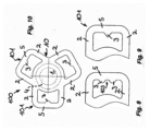
図1に示した平面図に認めることができるように、外側の縁側の保持部101は、弁座4の互いに反対の側で弁プレート10に設けられていてよい。これに対して、図10に示した弁プレート10は、3つの外側の縁側の保持部101を有している。これら3つの外側の縁側の保持部101は、閉鎖体1の全周にわたって均等に分配されて配置されている。外側の縁側の保持部101は、互いに結合されずに閉鎖体1にのみ係合している。図1および図10に示した弁プレートの各々の外側の縁側の保持部101は、少なくとも2つのウェブ2を有している。各1つの外側の縁側の保持部101のウェブは、閉鎖体1と反対側のウェブ端部でこの縁側の保持部101の結合ブラケット5を介して互いに結合されている。この結合ブラケット5の各々の内面は、弁ハウジングの、割り当てられた少なくとも1つの保持基部7に係合する。図1に認めることができるように、結合ブラケット5の各々の内面は、弁ハウジングの、割り当てられた少なくとも1つの保持基部7に係合し、各々の縁側の保持部101は、一対のウェブ2を有している。これらのウェブ2は、閉鎖体1と反対側の端部で1つの共通の結合ブラケット5を介して互いに結合されている。
As can be seen in the plan view shown in FIG. 1, the outer edge retaining features 101 may be provided on the
外側の縁側の保持部101の結合ブラケット5は、この結合ブラケット5にそれぞれ割り当てられたウェブ2を介して互いに分離されて閉鎖体1に結合されている。図1に認めることができるように、各々の縁側の保持部101は、割り当てられた少なくとも1つの保持基部7の、好ましくは相補的な対応ジオメトリと協働するセンタリングジオメトリを有している。図1に示した実施例では、各1つの縁側の保持部101の結合ブラケット5は、センタリング用または位置決め用の少なくとも1つの凸状成形部または凹状成形部を有している。この凸状成形部または凹状成形部は、割り当てられた少なくとも1つの保持基部7に設けられた相補的な対応異形成形部と協働する。各1つの縁側の保持部101の結合ブラケット5は、ほぼ中央に配置された、好ましくはほぼ突起状に形成された凸状成形部3を有している。図7、図8および図9に示した詳細図の比較から明らかなように、各1つの縁側の保持部101の結合ブラケット5は、センタリング用または位置決め用の少なくとも1つの凸状成形部3または凹状成形部103を有している。この凸状成形部3または凹状成形部103は、割り当てられた少なくとも1つの保持基部7に設けられた相補的な対応異形成形部と協働する。
The connecting
図7に示したように、各1つの縁側の保持部101の結合ブラケット5は、センタリング用または位置決め用の少なくとも1つの凸状成形部または凹状成形部を有していてよい。この凸状成形部または凹状成形部は、割り当てられた少なくとも1つの保持基部7に設けられた相補的な対応異形成形部と協働する。
As shown in FIG. 7, the connecting
図1に認めることができるように、弁プレート10の互いに反対の側に配置された縁側の保持部101のウェブ2は、好ましくは、閉鎖体1に対してほぼ接線方向に延びるほぼ1つの線内に対を成して配置されている。各1つの縁側の保持部101の、ウェブ2を互いに結合する結合ブラケット5は、それぞれ同縁側の保持部に割り当てられた保持基部7の、隣り合った周面部分領域に接触している。少なくとも1つの保持基部7は、割り当てられた結合ブラケット5により押圧される周面領域において、特に凸状に湾曲させられてまたは丸み付けられて形成されている。各1つの縁側の保持部101の、ウェブ2を互いに結合する結合ブラケット5は、それぞれ同縁側の保持部に割り当てられた保持基部7の、隣り合った周面部分領域に接触している。少なくとも1つの保持基部7は、割り当てられた結合ブラケット5により押圧される周面領域において、特に凸状に湾曲させられてまたは丸み付けられて形成されている。
As can be seen in FIG. 1, the
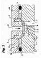
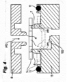
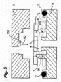
図2~図5から明らかなように、弁室14は、互いに接触した弁ハウジング部材8,15の間に画定されている。これらの弁ハウジング部材8,15は弁ハウジングを形成している。この弁ハウジングは、ダイヤフラムポンプのポンプヘッドの一体形の構成部材であってもよい。
As can be seen from Figures 2 to 5, the
例えば流入通路または流出通路の弁開口12,13を画定する弁座4は、図示の構成では、弁プレート10の外側の縁側の保持部101により形成される平面を越えて張り出している。結合ブラケット5は、この結合ブラケット5に割り当てられた保持基部7を介して両側側方に張り出しており、これによって、湾曲により、結合ブラケット5に結合されたウェブ2に外向きに予荷重が加えられている。この場合、各々の結合ブラケット5は、予荷重に起因した縁側の保持部101の変形が、結合ブラケット5の領域においてウェブ2の領域よりも大きいように形成されている。図1に認めることができるように、縁側の保持部101は、弁の開放位置(線b)における、弁プレート10の互いに反対の側に配置された凸状成形部同士の間の間隔の延長が、閉鎖位置(線a)と比較して半分よりも多く、結合ブラケット5の付加的な湾曲によって補償されているように形成されている。この場合、各々の保持基部7は、弁ハウジングの隣接平面に対して、弁プレート10の厚さよりも大きい高さを有している。図2および図3から明らかなように、弁座4は、弁ハウジングの隣接平面を越えて張り出しており、弁ハウジングの、弁座4と反対の側には、少なくとも1つの弁受け102が設けられている。この弁受け102は、弁ハウジングの隣接平面を越えて張り出していて、弁100の開放位置への閉鎖体1の最大の変位を制限している。
In the illustrated embodiment, the
弁プレート10は、互いに接触する弁ハウジング部材8,15の間の分離平面の密封に関して付加的な機能を引き受ける必要がないので、弁プレート10は、外周側で、少なくとも結合ブラケット5の領域において、特に外周全体全面にわたって弁ハウジングから離間させられていてよい。弁ハウジングを画定する弁ハウジング部材8,15同士の間には、間隔を置いて弁プレート10を取り囲む、弁プレート10と特に別個の少なくとも1つの環状シール部材11が設けられている。
Since the
弁100の弁プレート10は、外側の縁側の保持部101において縁側で保持され、弾性的に予荷重を受ける。結合ブラケット5に起因してブラケット弁と呼ばれることもある弁は、圧力差によって受動的に操作される。図1に示したように、弁プレート10をその外側の縁側の保持部101でもって保持基部7に取り付ける互いに反対側に位置する二対のウェブ2は、保持基部7を挟み込む側で少なくとも対を成して結合されており、結合ブラケット5の湾曲によって、縁側の保持部101のウェブ対は、常に引張り応力下にある。結合ブラケット5の、割り当てられた保持基部7に面した周面側には、センタリングジオメトリが設けられている。このセンタリングジオメトリは、保持基部7の、結合ブラケット5に隣り合った面に設けられた対応する対応成形部に存在していて、閉鎖体1を弁座4上に位置決めしている。
The
図1に示した実施例では、結合ブラケット5に設けられたセンタリングジオメトリは、ほぼ中央に配置された、突起状に形成された凸状成形部3によって形成されている。しかしながら、図8に示したように、結合ブラケット5はそのブラケット内面にこのような2つの凸状成形部3を有していてもよい。これら2つの凸状成形部3は、相互間に位置する、ほぼ中央に配置された凹状成形部103を介して互いに結合されている。
In the embodiment shown in FIG. 1, the centering geometry provided on the connecting
図9に示したように、結合ブラケット5の内面に設けられ、図示の構成では同じくほぼ中央に配置された凸状成形部は、矢尻状に形成されていてもよい。図9に示した結合ブラケット5のこの矢尻状の凸状成形部3も、保持基部(図示せず)に設けられた対応する対応成形部に係合する。
As shown in FIG. 9, the convex molding on the inner surface of the
図2と図4との比較もしくは図3と図5との比較から明らかなように、弁プレート10は、弁100の組付け時に弁ハウジング部材のうちの一方、図示の構成では、それぞれ下側の弁ハウジング部材15に載置される。長手方向Pf1ならびに弁座4の平面内でのウェブ2の予荷重は、組付け状態で互いに接触する弁ハウジング部材8,15同士を互いに嵌め合わせることによって達成される。組付け状態で互いに接触する弁ハウジング部材8,15の取付けジオメトリは、これらのハウジング部材8,15を手動でまたは場合により自動化して互いに嵌め合わせる際、付加的な組付けステップを必要とすることなしに弁プレート10の予荷重が得られるように、適合する導入斜面6によって形成されてよい。これによって、外側の縁側の保持部101の領域における機能的に重要な予荷重を省略する必要なしに、弁100の自動化された組付けも容易になる。
2 and 4 or 3 and 5, the
弁プレート10に対する弁ハウジング部材8,15における取付けジオメトリは、要求に応じて、図示の構成では下側に位置する弁ハウジング部材15または上側に位置する弁ハウジング部材8に配置されていてよい。しかしながら、簡単な組付けのためには、取付けジオメトリが、図2および図4に示した流入弁に対しても、図3および図5に示した流出弁に対しても、下側に位置する弁ハウジング部材15に設けられていると有利である。
The mounting geometry of the
結合ブラケット5に設けられた、図示の構成では凸状成形部3を有するセンタリングジオメトリによって、弁プレート10はその閉鎖体1で弁座4にわたって良好に位置決めされる。この位置決めひいては弁機能は、弁プレート10のために使用される材料の僅かな膨潤時でも失われていかない。この膨潤は、弁プレート10の、矢印方向Pf1で有効な弾性的な予荷重を外側の縁側の保持部101の領域で減少させるにすぎない。
The centering geometry of the connecting
閉鎖体1が弁100の閉鎖位置で弁座4に密に接触しているようにするために、この弁座4は、弁プレート10の縁側の保持部101の平面を僅かに越えて張り出している。この張出しの正確な寸法は、構成部材の誤差に関連している。図面に示した本発明に係る弁100では、この弁100の閉鎖機能は、公知の別の弁形態の事例ほど弁座4の張出しの正確な寸法に左右されない。このことは、各1つの縁側の保持部101の少なくとも2つのウェブ2による弁ハウジングへの弁プレート10の取付けによって達成される。これによって、弁プレート10がそれほど大幅に湾曲させられなくなる。
In order to ensure that the
長さに関して予荷重が加えられる別のプレート弁と比較して、図面に示した弁100では、自動化された組付けもより簡単に実現することができる。それぞれ少なくとも2つのウェブ2を縁側の保持部101に結合することによって、グリッパが弁プレート10を把持し、特に弁プレート10に弾性的に予荷重を加えることが容易になる。図面に示した弁100の自動化された組付けは、構成部材の構造によってさらに一層簡単にすることができる。つまり、このためには、図4および図5に示したように、弁プレート10が、下側に位置するケーシング部分15に載置され、両方の弁ケーシング部分8,15を組付け方向Pf2で互いに嵌め合わせて組み立てることによって、長手方向Pf1ならびに弁座4の平面内でのウェブ2もしくは結合ブラケット5の領域における外側の縁側の保持部101の予荷重が達成される。この場合、縁側の保持部101の領域における弁プレート10の予荷重は、成形斜面6によって実現される。
In comparison with other plate valves which are preloaded in length, the
外周側に配置される環状シール部材も弁プレート10に一体化されている公知の弁構成と比較して、図面に示したブラケット弁はスペースをほとんど必要としない。これによって、弁100が、例えばダイヤフラムポンプ(図示せず)の流入弁および/または流出弁として使用される際に隙間容積(デッドスペース)がより小さくなる。
Compared to known valve configurations in which the annular seal member arranged on the outer periphery is also integrated into the
図2~図5の総体的な考察から明らかなように、下側に位置する弁ハウジング部材15は、それぞれ弁プレート10の縁側の保持部に対する保持基部7を有する弁ハウジング部材である。図2および図3では、破線cが、閉鎖位置における弁100の中立線に相当しているのに対して、線dは、開放位置における弁100の中立線に相当している。各1つの縁側の保持部のウェブ2と結合ブラケット10とは、弁が開放されている場合、図1に示した線bの延長が、閉鎖状態における図1に示した線aと比べて大部分、しかしながら、少なくとも半分よりも多く、結合ブラケット5では付加的な湾曲によって補償され、ウェブでは引張り伸びによって結合ブラケット5ほど補償されないように形成されている。
2 to 5, the lower
図10には、弁の弁プレート10が示してあるが、この弁プレート10以外は示していない。図10に示した弁プレート10には、外側に位置する3つの縁側の保持部101が設けられている。これら3つの縁側の保持部101は、弁プレート10の全周にわたって均等な間隔を置いて配置されている。縁側の保持部の各々は、1つの結合ブラケット5を有している。この結合ブラケット5は、それぞれ一対のウェブ2を介して弁プレート10の、ここでも円形に形成された中央の閉鎖体1に結合されている。一対のウェブ2と1つの結合ブラケット5とから形成された縁側の保持部の各々の内面は、図1に示したように、弁ハウジングに設けられた対応する保持基部7に係合する。
10 shows the
1 閉鎖体
2 ウェブ
3 (結合ブラケットに設けられた)凸状成形部
4 弁座
5 結合ブラケット
6 成形斜面
7 保持基部
8 上側に位置する弁ハウジング部材
9 ウェブ2と閉鎖体1との間の結合領域
10 弁プレート
11 環状シール部材
12 流入開口
13 流出開口
14 弁室
15 下側に位置する弁ケーシング部分
100 弁
101 外側の縁側の保持部
102 弁受け
103 凹状成形部
Pf1 予荷重/引張り力の力方向
Pf2 弁ハウジング部材8,15同士を接合する際の力方向
a 閉鎖状態における、弁100の互いに反対の側に配置された凸状成形部3の間隔
b 弁100の開放位置における、弁プレート10の互いに反対の側に配置された凸状成形部3の間隔
c 閉鎖位置における弁の中立線
d 開放位置における弁の中立線
1
Claims (25)
前記外側の縁側の保持部(101)は、互いに結合されずに前記閉鎖体(1)にのみ係合しており、各々の外側の縁側の保持部(101)は、少なくとも2つのウェブ(2)を有し、各1つの外側の縁側の保持部(101)の前記ウェブ(2)は、1つの結合ブラケット(5)を介して互いに結合されており、前記結合ブラケット(5)の各々の内面は、前記弁ハウジングの、割り当てられた少なくとも1つの保持基部(7)に係合しており、前記結合ブラケット(5)は、割り当てられた前記保持基部(7)を介して両側側方に張り出しており、これによって、前記結合ブラケット(5)に湾曲によって外向きに予荷重が加えられていることを特徴とする、弁。 A valve (100) for a diaphragm pump, comprising a valve chamber (14) defined by a valve housing, in which at least one valve seat (4) is provided, which valve seat (4) cooperates with a valve plate (10) which is elastically preloaded in tension via an outer edge retaining portion (101) so that a closing body (1) of the valve plate (10) can be moved from a closed position, in which it rests tightly against the valve seat (4), to an open position against the elasticity of the valve plate (10) at least in the area of the outer edge retaining portion (101), the outer edge retaining portion (101) of the valve plate (10) having a web (2) and a connecting bracket (5) connected to a web end of the web (2) facing away from the closing body (1),
The outer edge retaining portions (101) are not connected to each other but only engage with the closure body (1), each outer edge retaining portion (101) has at least two webs (2), the webs (2) of each outer edge retaining portion (101) are connected to each other via a connecting bracket (5), the inner surface of each of the connecting brackets (5) engages with at least one assigned retaining base (7) of the valve housing, and the connecting brackets (5) overhang on both sides via the assigned retaining base (7), thereby preloading the connecting brackets (5) outwardly by bending .
少なくとも1つの流入弁および/または流出弁は、請求項1から24までのいずれか1項に従って形成されていることを特徴とする、ダイヤフラムポンプ。 A diaphragm pump having at least one inlet valve and at least one outlet valve,
10. A diaphragm pump, characterized in that at least one inlet valve and/or outlet valve is designed according to one of claims 1 to 24 .
Applications Claiming Priority (3)
| Application Number | Priority Date | Filing Date | Title |
|---|---|---|---|
| DE102020112696.4 | 2020-05-11 | ||
| DE102020112696.4A DE102020112696B4 (en) | 2020-05-11 | 2020-05-11 | Valve and diaphragm pump with inlet and outlet valves |
| PCT/EP2021/061254 WO2021228567A1 (en) | 2020-05-11 | 2021-04-29 | Valve and diaphragm pump with inlet and outlet valves |
Publications (2)
| Publication Number | Publication Date |
|---|---|
| JP2023531363A JP2023531363A (en) | 2023-07-24 |
| JP7581377B2 true JP7581377B2 (en) | 2024-11-12 |
Family
ID=75769588
Family Applications (1)
| Application Number | Title | Priority Date | Filing Date |
|---|---|---|---|
| JP2022568539A Active JP7581377B2 (en) | 2020-05-11 | 2021-04-29 | Diaphragm pump with valve and inlet and outlet valves - Patents.com |
Country Status (6)
| Country | Link |
|---|---|
| US (1) | US11959555B2 (en) |
| EP (1) | EP4088053B1 (en) |
| JP (1) | JP7581377B2 (en) |
| CN (1) | CN115777049A (en) |
| DE (1) | DE102020112696B4 (en) |
| WO (1) | WO2021228567A1 (en) |
Families Citing this family (2)
| Publication number | Priority date | Publication date | Assignee | Title |
|---|---|---|---|---|
| DE102021105373A1 (en) | 2021-03-05 | 2022-09-08 | Mann+Hummel Gmbh | Filter element, filter element arrangement and filter system with a filter element arrangement |
| DE102023103702A1 (en) * | 2023-02-15 | 2024-08-22 | Vat Holding Ag | Pressure relief valve |
Citations (5)
| Publication number | Priority date | Publication date | Assignee | Title |
|---|---|---|---|---|
| EP0336307A2 (en) | 1988-04-06 | 1989-10-11 | Wiser Oy | Double-valve and membrane arrangement of non-return valve |
| EP1555469A1 (en) | 2004-01-15 | 2005-07-20 | Knf Flodos Ag | Check valve |
| DE102005005473A1 (en) | 2005-02-04 | 2006-08-17 | Polytec Automotive Gmbh & Co. Kg | One-piece spring plate valve for switchable mini cyclone, has bending arms charged with positive and negative bending moments in such a manner that locking plate is lifted with adjacent opening pressure by parallel movement of plate |
| US20130331823A1 (en) | 2012-05-15 | 2013-12-12 | Smith & Nephew Plc | Negative pressure wound therapy apparatus |
| DE102016002071A1 (en) | 2016-01-31 | 2017-08-03 | Schwarzer Precision GmbH & Co. KG | Valve segment and valve arrangement |
Family Cites Families (11)
| Publication number | Priority date | Publication date | Assignee | Title |
|---|---|---|---|---|
| US3039487A (en) * | 1960-09-26 | 1962-06-19 | American Motors Corp | Refrigerating apparatus |
| US5960825A (en) * | 1997-06-26 | 1999-10-05 | Copeland Corporation | Laser hardened reed valve |
| CA2350595A1 (en) * | 1998-11-16 | 2000-05-25 | California Institute Of Technology | Parylene micro check valve and fabrication method thereof |
| DE202004009673U1 (en) | 2004-05-05 | 2005-09-15 | Hengst Gmbh & Co Kg | Valve arrangement in a crankcase ventilation |
| DE112007000722B4 (en) | 2006-03-29 | 2013-07-04 | Murata Manufacturing Co., Ltd. | micropump |
| DE102008043309A1 (en) | 2008-10-30 | 2010-05-06 | Robert Bosch Gmbh | Diaphragm pump with a multipart pump housing |
| DE102010018200A1 (en) * | 2010-04-26 | 2011-10-27 | Schaeffler Technologies Gmbh & Co. Kg | Control valve, in particular proportional valve |
| DE102010032251A1 (en) * | 2010-07-26 | 2012-01-26 | Schaeffler Technologies Gmbh & Co. Kg | Check valve and hydraulic valve with built-in check valve |
| DE202016001148U1 (en) * | 2016-01-31 | 2017-05-04 | Schwarzer Precision GmbH & Co. KG | Valve segment and valve arrangement |
| DE102016115025B3 (en) * | 2016-08-12 | 2017-09-14 | Feluwa Pumpen Gmbh | Valve |
| TWI666384B (en) * | 2018-06-08 | 2019-07-21 | 科際精密股份有限公司 | Diaphragm pump and value plate thereof |
-
2020
- 2020-05-11 DE DE102020112696.4A patent/DE102020112696B4/en active Active
-
2021
- 2021-04-29 WO PCT/EP2021/061254 patent/WO2021228567A1/en not_active Ceased
- 2021-04-29 JP JP2022568539A patent/JP7581377B2/en active Active
- 2021-04-29 EP EP21722831.1A patent/EP4088053B1/en active Active
- 2021-04-29 US US17/920,094 patent/US11959555B2/en active Active
- 2021-04-29 CN CN202180033918.4A patent/CN115777049A/en active Pending
Patent Citations (5)
| Publication number | Priority date | Publication date | Assignee | Title |
|---|---|---|---|---|
| EP0336307A2 (en) | 1988-04-06 | 1989-10-11 | Wiser Oy | Double-valve and membrane arrangement of non-return valve |
| EP1555469A1 (en) | 2004-01-15 | 2005-07-20 | Knf Flodos Ag | Check valve |
| DE102005005473A1 (en) | 2005-02-04 | 2006-08-17 | Polytec Automotive Gmbh & Co. Kg | One-piece spring plate valve for switchable mini cyclone, has bending arms charged with positive and negative bending moments in such a manner that locking plate is lifted with adjacent opening pressure by parallel movement of plate |
| US20130331823A1 (en) | 2012-05-15 | 2013-12-12 | Smith & Nephew Plc | Negative pressure wound therapy apparatus |
| DE102016002071A1 (en) | 2016-01-31 | 2017-08-03 | Schwarzer Precision GmbH & Co. KG | Valve segment and valve arrangement |
Also Published As
| Publication number | Publication date |
|---|---|
| WO2021228567A1 (en) | 2021-11-18 |
| EP4088053C0 (en) | 2023-08-23 |
| CN115777049A (en) | 2023-03-10 |
| DE102020112696B4 (en) | 2022-08-18 |
| JP2023531363A (en) | 2023-07-24 |
| DE102020112696A1 (en) | 2021-11-11 |
| EP4088053A1 (en) | 2022-11-16 |
| US20230160482A1 (en) | 2023-05-25 |
| US11959555B2 (en) | 2024-04-16 |
| EP4088053B1 (en) | 2023-08-23 |
Similar Documents
| Publication | Publication Date | Title |
|---|---|---|
| JP5312545B2 (en) | valve | |
| JP7581377B2 (en) | Diaphragm pump with valve and inlet and outlet valves - Patents.com | |
| TWI548827B (en) | Diaphragm and diaphragm valve | |
| EP2231262B1 (en) | A check valve, in particular for medical applications | |
| CN102734490B (en) | Diaphragm valve | |
| JP4851413B2 (en) | Band type filter | |
| JPH0615186Y2 (en) | Direction switching valve | |
| US6786471B2 (en) | Diaphragm valve | |
| CN104350317B (en) | Diaphragm valve | |
| US8152491B2 (en) | Pump using unimorph diaphragm | |
| JP2003148549A (en) | Hydraulic vibration damping support | |
| AU2017210484B2 (en) | Valve | |
| JP4357296B2 (en) | Inlet or outlet valve for pump | |
| KR100927104B1 (en) | Pipe flange connection structure of vehicle air conditioner system | |
| CN107763215B (en) | Sealing system and valve provided with sealing system | |
| JP6655886B2 (en) | Check valve | |
| JP6896081B2 (en) | valve | |
| CN114645963B (en) | Valve housing for valves | |
| KR102694668B1 (en) | Telescopic butterfly valve with improved watertightness | |
| CN114763862A (en) | Gas valve | |
| KR101310856B1 (en) | Acoustic muffler for a hermetic compressor | |
| TW202443056A (en) | Diaphragm, valve having the same, and method for manufacturing the diaphragm | |
| CN119244778A (en) | Check valve | |
| KR20060022328A (en) | Diaphragm used for diaphragm pump and diaphragm pump | |
| CN116892625A (en) | The electromagnetic valve |
Legal Events
| Date | Code | Title | Description |
|---|---|---|---|
| A529 | Written submission of copy of amendment under article 34 pct |
Free format text: JAPANESE INTERMEDIATE CODE: A529 Effective date: 20221110 |
|
| A621 | Written request for application examination |
Free format text: JAPANESE INTERMEDIATE CODE: A621 Effective date: 20231113 |
|
| A131 | Notification of reasons for refusal |
Free format text: JAPANESE INTERMEDIATE CODE: A131 Effective date: 20240402 |
|
| A521 | Request for written amendment filed |
Free format text: JAPANESE INTERMEDIATE CODE: A523 Effective date: 20240701 |
|
| TRDD | Decision of grant or rejection written | ||
| A01 | Written decision to grant a patent or to grant a registration (utility model) |
Free format text: JAPANESE INTERMEDIATE CODE: A01 Effective date: 20241002 |
|
| A61 | First payment of annual fees (during grant procedure) |
Free format text: JAPANESE INTERMEDIATE CODE: A61 Effective date: 20241030 |
|
| R150 | Certificate of patent or registration of utility model |
Ref document number: 7581377 Country of ref document: JP Free format text: JAPANESE INTERMEDIATE CODE: R150 |