JP7581365B2 - Reactor and method for the conversion of carbonaceous materials - Patents.com - Google Patents
Reactor and method for the conversion of carbonaceous materials - Patents.com Download PDFInfo
- Publication number
- JP7581365B2 JP7581365B2 JP2022559867A JP2022559867A JP7581365B2 JP 7581365 B2 JP7581365 B2 JP 7581365B2 JP 2022559867 A JP2022559867 A JP 2022559867A JP 2022559867 A JP2022559867 A JP 2022559867A JP 7581365 B2 JP7581365 B2 JP 7581365B2
- Authority
- JP
- Japan
- Prior art keywords
- reactor
- gas
- carbonaceous
- conduit
- carbonaceous material
- Prior art date
- Legal status (The legal status is an assumption and is not a legal conclusion. Google has not performed a legal analysis and makes no representation as to the accuracy of the status listed.)
- Active
Links
Images

Classifications
-
- B—PERFORMING OPERATIONS; TRANSPORTING
- B01—PHYSICAL OR CHEMICAL PROCESSES OR APPARATUS IN GENERAL
- B01J—CHEMICAL OR PHYSICAL PROCESSES, e.g. CATALYSIS OR COLLOID CHEMISTRY; THEIR RELEVANT APPARATUS
- B01J6/00—Heat treatments such as Calcining; Fusing ; Pyrolysis
- B01J6/001—Calcining
- B01J6/004—Calcining using hot gas streams in which the material is moved
-
- B—PERFORMING OPERATIONS; TRANSPORTING
- B01—PHYSICAL OR CHEMICAL PROCESSES OR APPARATUS IN GENERAL
- B01J—CHEMICAL OR PHYSICAL PROCESSES, e.g. CATALYSIS OR COLLOID CHEMISTRY; THEIR RELEVANT APPARATUS
- B01J6/00—Heat treatments such as Calcining; Fusing ; Pyrolysis
- B01J6/008—Pyrolysis reactions
-
- B—PERFORMING OPERATIONS; TRANSPORTING
- B01—PHYSICAL OR CHEMICAL PROCESSES OR APPARATUS IN GENERAL
- B01J—CHEMICAL OR PHYSICAL PROCESSES, e.g. CATALYSIS OR COLLOID CHEMISTRY; THEIR RELEVANT APPARATUS
- B01J8/00—Chemical or physical processes in general, conducted in the presence of fluids and solid particles; Apparatus for such processes
- B01J8/0015—Feeding of the particles in the reactor; Evacuation of the particles out of the reactor
- B01J8/003—Feeding of the particles in the reactor; Evacuation of the particles out of the reactor in a downward flow
-
- B—PERFORMING OPERATIONS; TRANSPORTING
- B01—PHYSICAL OR CHEMICAL PROCESSES OR APPARATUS IN GENERAL
- B01J—CHEMICAL OR PHYSICAL PROCESSES, e.g. CATALYSIS OR COLLOID CHEMISTRY; THEIR RELEVANT APPARATUS
- B01J8/00—Chemical or physical processes in general, conducted in the presence of fluids and solid particles; Apparatus for such processes
- B01J8/005—Separating solid material from the gas/liquid stream
-
- B—PERFORMING OPERATIONS; TRANSPORTING
- B01—PHYSICAL OR CHEMICAL PROCESSES OR APPARATUS IN GENERAL
- B01J—CHEMICAL OR PHYSICAL PROCESSES, e.g. CATALYSIS OR COLLOID CHEMISTRY; THEIR RELEVANT APPARATUS
- B01J8/00—Chemical or physical processes in general, conducted in the presence of fluids and solid particles; Apparatus for such processes
- B01J8/0095—Chemical or physical processes in general, conducted in the presence of fluids and solid particles; Apparatus for such processes in which two different types of particles react with each other
-
- B—PERFORMING OPERATIONS; TRANSPORTING
- B01—PHYSICAL OR CHEMICAL PROCESSES OR APPARATUS IN GENERAL
- B01J—CHEMICAL OR PHYSICAL PROCESSES, e.g. CATALYSIS OR COLLOID CHEMISTRY; THEIR RELEVANT APPARATUS
- B01J8/00—Chemical or physical processes in general, conducted in the presence of fluids and solid particles; Apparatus for such processes
- B01J8/16—Chemical or physical processes in general, conducted in the presence of fluids and solid particles; Apparatus for such processes with particles being subjected to vibrations or pulsations
-
- B—PERFORMING OPERATIONS; TRANSPORTING
- B01—PHYSICAL OR CHEMICAL PROCESSES OR APPARATUS IN GENERAL
- B01J—CHEMICAL OR PHYSICAL PROCESSES, e.g. CATALYSIS OR COLLOID CHEMISTRY; THEIR RELEVANT APPARATUS
- B01J8/00—Chemical or physical processes in general, conducted in the presence of fluids and solid particles; Apparatus for such processes
- B01J8/18—Chemical or physical processes in general, conducted in the presence of fluids and solid particles; Apparatus for such processes with fluidised particles
- B01J8/1809—Controlling processes
-
- B—PERFORMING OPERATIONS; TRANSPORTING
- B01—PHYSICAL OR CHEMICAL PROCESSES OR APPARATUS IN GENERAL
- B01J—CHEMICAL OR PHYSICAL PROCESSES, e.g. CATALYSIS OR COLLOID CHEMISTRY; THEIR RELEVANT APPARATUS
- B01J8/00—Chemical or physical processes in general, conducted in the presence of fluids and solid particles; Apparatus for such processes
- B01J8/18—Chemical or physical processes in general, conducted in the presence of fluids and solid particles; Apparatus for such processes with fluidised particles
- B01J8/1818—Feeding of the fluidising gas
- B01J8/1827—Feeding of the fluidising gas the fluidising gas being a reactant
-
- B—PERFORMING OPERATIONS; TRANSPORTING
- B01—PHYSICAL OR CHEMICAL PROCESSES OR APPARATUS IN GENERAL
- B01J—CHEMICAL OR PHYSICAL PROCESSES, e.g. CATALYSIS OR COLLOID CHEMISTRY; THEIR RELEVANT APPARATUS
- B01J8/00—Chemical or physical processes in general, conducted in the presence of fluids and solid particles; Apparatus for such processes
- B01J8/18—Chemical or physical processes in general, conducted in the presence of fluids and solid particles; Apparatus for such processes with fluidised particles
- B01J8/1836—Heating and cooling the reactor
-
- B—PERFORMING OPERATIONS; TRANSPORTING
- B01—PHYSICAL OR CHEMICAL PROCESSES OR APPARATUS IN GENERAL
- B01J—CHEMICAL OR PHYSICAL PROCESSES, e.g. CATALYSIS OR COLLOID CHEMISTRY; THEIR RELEVANT APPARATUS
- B01J8/00—Chemical or physical processes in general, conducted in the presence of fluids and solid particles; Apparatus for such processes
- B01J8/18—Chemical or physical processes in general, conducted in the presence of fluids and solid particles; Apparatus for such processes with fluidised particles
- B01J8/24—Chemical or physical processes in general, conducted in the presence of fluids and solid particles; Apparatus for such processes with fluidised particles according to "fluidised-bed" technique
- B01J8/32—Chemical or physical processes in general, conducted in the presence of fluids and solid particles; Apparatus for such processes with fluidised particles according to "fluidised-bed" technique with introduction into the fluidised bed of more than one kind of moving particles
-
- C—CHEMISTRY; METALLURGY
- C04—CEMENTS; CONCRETE; ARTIFICIAL STONE; CERAMICS; REFRACTORIES
- C04B—LIME, MAGNESIA; SLAG; CEMENTS; COMPOSITIONS THEREOF, e.g. MORTARS, CONCRETE OR LIKE BUILDING MATERIALS; ARTIFICIAL STONE; CERAMICS; REFRACTORIES; TREATMENT OF NATURAL STONE
- C04B7/00—Hydraulic cements
- C04B7/36—Manufacture of hydraulic cements in general
- C04B7/43—Heat treatment, e.g. precalcining, burning, melting; Cooling
- C04B7/44—Burning; Melting
- C04B7/4407—Treatment or selection of the fuel therefor, e.g. use of hazardous waste as secondary fuel ; Use of particular energy sources, e.g. waste hot gases from other processes
- C04B7/4423—Waste or refuse used as fuel
-
- C—CHEMISTRY; METALLURGY
- C04—CEMENTS; CONCRETE; ARTIFICIAL STONE; CERAMICS; REFRACTORIES
- C04B—LIME, MAGNESIA; SLAG; CEMENTS; COMPOSITIONS THEREOF, e.g. MORTARS, CONCRETE OR LIKE BUILDING MATERIALS; ARTIFICIAL STONE; CERAMICS; REFRACTORIES; TREATMENT OF NATURAL STONE
- C04B7/00—Hydraulic cements
- C04B7/36—Manufacture of hydraulic cements in general
- C04B7/43—Heat treatment, e.g. precalcining, burning, melting; Cooling
- C04B7/44—Burning; Melting
- C04B7/4407—Treatment or selection of the fuel therefor, e.g. use of hazardous waste as secondary fuel ; Use of particular energy sources, e.g. waste hot gases from other processes
- C04B7/4446—Treatment or selection of the fuel therefor, e.g. use of hazardous waste as secondary fuel ; Use of particular energy sources, e.g. waste hot gases from other processes the fuel being treated in a separate gasifying or decomposing chamber, e.g. a separate combustion chamber
-
- C—CHEMISTRY; METALLURGY
- C04—CEMENTS; CONCRETE; ARTIFICIAL STONE; CERAMICS; REFRACTORIES
- C04B—LIME, MAGNESIA; SLAG; CEMENTS; COMPOSITIONS THEREOF, e.g. MORTARS, CONCRETE OR LIKE BUILDING MATERIALS; ARTIFICIAL STONE; CERAMICS; REFRACTORIES; TREATMENT OF NATURAL STONE
- C04B7/00—Hydraulic cements
- C04B7/36—Manufacture of hydraulic cements in general
- C04B7/43—Heat treatment, e.g. precalcining, burning, melting; Cooling
- C04B7/44—Burning; Melting
- C04B7/45—Burning; Melting in fluidised beds, e.g. spouted beds
-
- B—PERFORMING OPERATIONS; TRANSPORTING
- B01—PHYSICAL OR CHEMICAL PROCESSES OR APPARATUS IN GENERAL
- B01J—CHEMICAL OR PHYSICAL PROCESSES, e.g. CATALYSIS OR COLLOID CHEMISTRY; THEIR RELEVANT APPARATUS
- B01J2208/00—Processes carried out in the presence of solid particles; Reactors therefor
- B01J2208/00008—Controlling the process
- B01J2208/00017—Controlling the temperature
- B01J2208/00327—Controlling the temperature by direct heat exchange
- B01J2208/00336—Controlling the temperature by direct heat exchange adding a temperature modifying medium to the reactants
- B01J2208/0038—Solids
-
- B—PERFORMING OPERATIONS; TRANSPORTING
- B01—PHYSICAL OR CHEMICAL PROCESSES OR APPARATUS IN GENERAL
- B01J—CHEMICAL OR PHYSICAL PROCESSES, e.g. CATALYSIS OR COLLOID CHEMISTRY; THEIR RELEVANT APPARATUS
- B01J2208/00—Processes carried out in the presence of solid particles; Reactors therefor
- B01J2208/00008—Controlling the process
- B01J2208/0061—Controlling the level
-
- B—PERFORMING OPERATIONS; TRANSPORTING
- B01—PHYSICAL OR CHEMICAL PROCESSES OR APPARATUS IN GENERAL
- B01J—CHEMICAL OR PHYSICAL PROCESSES, e.g. CATALYSIS OR COLLOID CHEMISTRY; THEIR RELEVANT APPARATUS
- B01J2208/00—Processes carried out in the presence of solid particles; Reactors therefor
- B01J2208/00796—Details of the reactor or of the particulate material
- B01J2208/00991—Disengagement zone in fluidised-bed reactors
Landscapes
- Chemical & Material Sciences (AREA)
- Organic Chemistry (AREA)
- Chemical Kinetics & Catalysis (AREA)
- Engineering & Computer Science (AREA)
- Ceramic Engineering (AREA)
- Combustion & Propulsion (AREA)
- Physics & Mathematics (AREA)
- Thermal Sciences (AREA)
- Materials Engineering (AREA)
- Structural Engineering (AREA)
- Devices And Processes Conducted In The Presence Of Fluids And Solid Particles (AREA)
- Carbon And Carbon Compounds (AREA)
Description
本発明は、代替燃料などの炭素質燃料を還元条件下で揮発性物質と変換材料とに変換し、揮発性物質を実質的に分離する方法に関する。本発明は、この方法を実行するのに適した反応器にさらに関する。 The present invention relates to a method for converting a carbonaceous fuel, such as an alternative fuel, under reducing conditions into volatile matter and a converted material, and substantially separating the volatile matter. The present invention further relates to a reactor suitable for carrying out the method.
セメントの製造は、CO2などの排出物の大きな放出源であることが知られている。この製造をより持続可能にするために、代替燃料を利用してセメント製造作業に熱エネルギーを供給することが望ましい。これまで、これは、か焼炉に代替燃料を直接投入することによって利用されていた。しかしながら、このような燃料の乾燥とその後の脱揮発分に要する時間は、燃料の含水量、燃料粒子の大きさ及び形状、並びに燃料の化学組成に依存し、これらすべては、代替燃料に対して大きく変化する。代替燃料の滞留時間が不十分な場合、典型的には、粒子の滞留時間が限られることにより、か焼炉での代替燃料の燃焼が不完全になり、か焼炉の温度プロファイルが影響を受ける。その結果、ほとんどの例では、か焼炉が代替燃料から得ることができる熱エネルギーの量は限られる。 The production of cement is known to be a large source of emissions such as CO2 . To make this production more sustainable, it is desirable to utilize alternative fuels to provide thermal energy to the cement manufacturing operation. In the past, this has been utilized by directly feeding the alternative fuel into the calciner. However, the time required for drying and subsequent devolatilization of such fuels depends on the moisture content of the fuel, the size and shape of the fuel particles, and the chemical composition of the fuel, all of which vary greatly for the alternative fuel. Insufficient residence time of the alternative fuel typically results in incomplete combustion of the alternative fuel in the calciner due to the limited residence time of the particles, and affects the temperature profile of the calciner. As a result, in most instances, the amount of thermal energy that the calciner can obtain from the alternative fuel is limited.
セメントは高温で製造され、したがって、セメント製造設備は代替燃料を利用するのに望ましい設備となり得る。それは、セメント原料を加熱するためにすでに使用されているエネルギーの一部は、低品位の代替燃料を変換するように、又は有害廃棄物を安全に燃やすように利用することができるからである。セメント原料ミールは粉末を形成する微粒子からなり、それは流動化することが困難である。その主な理由の1つは、粒子凝集を促進する粒子間凝集力が大きいことである。1973年、D.Geldartは、粉末をその流動化特性に従って分類する粉末分類システムを開発した(Geldart,D.,Powder Technol.,7,(1973),285)。Geldartの分類システムのタイプの1つは、流動化に適さないことによって特徴付けられたタイプCの材料、又はGeldart Cの材料である。セメント原料ミールは、このようなGeldart C粒子を多量に含んでおり、Geldart C材料のような流動挙動を示す。したがって、このような材料を流動化させようと試みると、亀裂及び溝が生じ、その結果、流動化が乏しく不安定になる。 Cement is produced at high temperatures, and therefore cement manufacturing facilities may be desirable facilities for utilizing alternative fuels, since some of the energy already used to heat cement raw materials can be utilized to convert low-grade alternative fuels or safely burn hazardous waste. Cement raw meal consists of fine particles that form powders, which are difficult to fluidize. One of the main reasons is the large interparticle cohesive forces that promote particle aggregation. In 1973, D. Geldart developed a powder classification system that classifies powders according to their fluidization characteristics (Geldart, D., Powder Technol., 7, (1973), 285). One type of Geldart classification system is Type C material, or Geldart C material, characterized by its inability to be fluidized. Cement raw meal contains a large amount of such Geldart C particles and exhibits flow behavior like Geldart C material. Therefore, attempts to fluidize such materials result in cracks and grooves, resulting in poor and unstable fluidization.
Geldart C材料は、典型的には30マイクロメートルより小さく、凝集性であると考えられる。この大きさの粒子は、単一の独立した粒子というよりも、粒子クラスタとしてふるまう傾向がある。 Geldart C material is typically smaller than 30 micrometers and is considered to be cohesive. Particles of this size tend to behave as particle clusters rather than single, discrete particles.
粗い粒子と細かい粒子との混合物の流動化挙動は、広い組成範囲の中の細粒部分の流動化挙動によって規定される。したがって、微粒子のセメント原料ミールと粗いチャー粒子との混合物は、典型的には、セメント原料ミールと同様の流動化挙動を示し、粗粒部分が支配的になるときだけ、粗い粒子の流動化特性が流動化挙動を決める。 The fluidization behavior of a mixture of coarse and fine particles is determined by the fluidization behavior of the fine fraction over a wide compositional range. Thus, a mixture of fine cement raw meal and coarse char particles will typically exhibit fluidization behavior similar to that of the cement raw meal, and only when the coarse fraction becomes dominant do the fluidization properties of the coarse particles determine the fluidization behavior.
欧州特許第3405728号では、代替燃料は、ガスのパルスが粒子を流動化させて、固体の反応器内の移動をしやすくするU字形ループシール反応器内で初期熱分解を受けることによって利用される。運転時、還元雰囲気中で代替燃料と高温のセメントミールとを混合すると、大量のガスが生じる。このような解決策では、定常運転を行うためには適切な大きさが重要であり、その結果、設置面積が大きくなり、設備投資が増大することがある。定常運転中、パルス状空気は高密度床を形成し、反応器内の固体の流れはプラグフローパターンである。高密度床に達する前に燃料と高温のセメントミールが適切に混合されることが重要であり、そうでないと、ホットスポット又はコールドスポットが形成され、低変換又は高温腐食の危険性につながることがある。 In EP 3405728, alternative fuels are utilized by undergoing initial pyrolysis in a U-shaped loop-seal reactor where pulses of gas fluidize the particles to facilitate solids movement through the reactor. During operation, mixing of the alternative fuel with hot cement meal in a reducing atmosphere produces large amounts of gas. Proper sizing is important for such solutions to provide steady-state operation, which can result in a large footprint and increased capital investment. During steady-state operation, the pulsed air creates a dense bed and the flow of solids in the reactor is in a plug flow pattern. It is important that the fuel and hot cement meal are properly mixed before reaching the dense bed, otherwise hot or cold spots can form, leading to low conversion or risk of high temperature corrosion.
代替燃料は、典型的には、セメントミールよりも実質的に大きな固体粒子からなることがある。したがって、ミール床より密度の大きな粒子は、ミール床から沈降することがある。これは、炭素質材料、並びに石及び金属などの非炭素質粒子の両方を含むことがある。セメントミールより大きな粒子が導入されることに加え、粒子はまた、床で凝集又は合体してより大きな粒子、塊、又は堆積物を形成することがある。効果的にエアーレーションされていない床の領域があると、床の材料が固まりになる傾向がある場合、特に堆積物を形成しやすい。これは、高温のセメントキルンの揮発性物質、又は部分的に溶けた炭素質材料によって促進される。沈降は効果的なエアーレーションを妨げることがあり、時間が経つにつれ、エアーレーションされたセメントミールが流れる導管のかなりの部分を塞ぐことがある。 The alternative fuel may typically consist of solid particles substantially larger than the cement meal. Thus, particles that are denser than the meal bed may settle out of the meal bed. This may include both carbonaceous material and non-carbonaceous particles such as stone and metal. In addition to introducing particles larger than the cement meal, the particles may also aggregate or coalesce in the bed to form larger particles, clumps, or deposits. Areas of the bed that are not effectively aerated are particularly susceptible to deposit formation if the bed material tends to agglomerate. This is facilitated by hot cement kiln volatiles or partially dissolved carbonaceous material. Settling may prevent effective aeration and over time may block a significant portion of the conduit through which the aerated cement meal flows.
したがって、代替燃料を効率的に利用することができ、適切なエアーレーションを行うことができ、運転を妨げることのある堆積物の形成及び沈降の危険性を低減することができる新規の反応器及び方法を有することは有利であろう。 It would therefore be advantageous to have new reactors and methods that can efficiently utilize alternative fuels, provide proper aeration, and reduce the risk of deposit formation and settling that can impede operation.
したがって、このような背景では、本発明の目的は、先行技術の欠点のいくつかを軽減することができる方法を提供することである。本発明の第1の態様では、これら及びさらなる目的は、
変換温度を有する炭素質材料を供給するステップと、
炭素質材料の変換温度よりも高い温度を有する粉末材料を供給するステップと、
炭素をCO2に部分的にだけ酸化するように構成された雰囲気中で炭素質材料と粉末材料とを接触させて、炭素質材料を、変換された材料と揮発性生成物とに少なくとも部分的に変換するステップと、
揮発性生成物を含むガス流を実質的に上方向に向けることによって比重により分離して、揮発性生成物を実質的に含む第1の部分と、追加成分を実質的に含む第2の部分とを提供するステップとを含み、炭素質材料と粉末材料との間の接触が、少なくとも2つの異なる流れ形態で起きる、炭素質材料の変換のための方法によって得られる。
In this context, it is therefore an object of the present invention to provide a method that can alleviate some of the drawbacks of the prior art. In a first aspect of the present invention, these and further objects are:
providing a carbonaceous material having a conversion temperature;
providing a powder material having a temperature higher than a conversion temperature of the carbonaceous material;
contacting the carbonaceous material with the powdered material in an atmosphere configured to only partially oxidize the carbon to CO2 to at least partially convert the carbonaceous material into a converted material and a volatile product;
and separating the gas stream containing the volatile products by gravity by directing the gas stream containing the volatile products substantially upwardly to provide a first portion substantially containing the volatile products and a second portion substantially containing the additional component, wherein contact between the carbonaceous material and the powder material occurs in at least two different flow regimes.
この方法は、炭素質材料を、変換された材料と揮発性生成物とに効率的に変換し、それらは分離されて、したがって別々にさらに処理することができる。揮発性物質は、例えば、燃料として使用することができる。変換プロセスへのエネルギー担体として固体材料を使用することの利点は、特に、生成物の流れに存在するガスがより少なく、典型的には不活性であることである。加えて、粉末材料の熱吸収は温度を安定させるのに役立ち、それによって、吸熱反応による温度低下、及び、例えば、炭素質材料の部分酸化による温度上昇に対して弾力性のあるプロセスを提供する。 The method efficiently converts the carbonaceous material into converted material and volatile products, which can be separated and therefore further processed separately. The volatile materials can be used, for example, as fuel. The advantage of using a solid material as the energy carrier to the conversion process is, among other things, that gases present in the product stream are less and typically inert. In addition, the heat absorption of the powdered material helps to stabilize the temperature, thereby providing a process that is resilient to temperature drops due to endothermic reactions and temperature increases due, for example, to partial oxidation of the carbonaceous material.
炭素質材料と粉末材料とが接触すると、炭素質材料が変換されて揮発性生成物が形成される。揮発性生成物はプロセス条件ではガスの形態であり、固体材料よりも大きな体積を有するので、揮発性生成物が形成されると実質的に上向きのガス流が生じる。ガス流の速度が固体の飛沫同伴速度より速い場合、ガス流は粒子を実質的に上方向に運ぶことができる。 When the carbonaceous material comes into contact with the powdered material, the carbonaceous material is converted to form a volatile product. The volatile product is in gas form at process conditions and has a larger volume than the solid material, so that a substantial upward gas flow occurs as the volatile product is formed. If the velocity of the gas flow is greater than the entrainment velocity of the solids, the gas flow can carry the particles in a substantial upward direction.
炭素質材料、粉末材料、及び/又は変換された材料が少なくとも2つの異なる流れ形態で接触するように、例えば、粉末材料の入口温度、粉末材料の量、及び/又は炭素質材料と粉末材料との接触時間を調節することにより、揮発性物質の発生が制御されるべきである。流れ形態は、下部の高密度な相と、より多くの揮発性物質を含む上部の希薄な相とであることが好ましい。希薄な相は、炭素質材料及び粉末材料を上向きの流れにする揮発性物質の形成及び上向きの流れによって形成される。揮発性物質を含むガスと炭素質材料及び粉末材料との上向きの流れは、ガスが第1の部分に分離されるまで続き、その後、炭素質材料及び粉末材料は重力により下向きに流れる。 The generation of volatiles should be controlled, for example, by adjusting the inlet temperature of the powder material, the amount of powder material, and/or the contact time of the carbonaceous material with the powder material, so that the carbonaceous material, the powder material, and/or the converted material are contacted in at least two different flow regimes. The flow regime is preferably a lower dense phase and an upper dilute phase containing more volatiles. The dilute phase is formed by the formation and upward flow of volatiles that causes the carbonaceous material and the powder material to flow upward. The upward flow of the gas containing volatiles and the carbonaceous material and the powder material continues until the gas is separated into a first portion, after which the carbonaceous material and the powder material flow downward by gravity.
2つの流れ形態により、炭素質材料と粉体材料とはより良く混合及び接触し、より安定した変換状態となってホットスポット及びコールドスポットの形成を回避する。
粉末材料とは、粒径分布に関係なく、パルス状のエアーレーションを受けたときに粉末のように挙動し、この挙動を損なわない濃度まで他の固体成分を含む材料を意味する。これは、一例として、セメントミールの場合がある。
The two flow regimes allow for better mixing and contact of the carbonaceous material with the powdered material, resulting in more stable conversion conditions and avoiding the formation of hot and cold spots.
By powdery material is meant a material, regardless of particle size distribution, which when subjected to pulsed aeration behaves like a powder and contains other solid components up to a concentration that does not impair this behavior. This is the case, for example, for cement meal.
追加成分は、粉末材料、変換された材料、及び、任意選択で、変換されなかった又は部分的に変換された炭素質材料を含む場合がある。
炭素質材料は炭素を含み、炭素に蓄えられたエネルギーを有する材料であり、その結果、炭素質材料を燃料として利用することができる。炭素質材料は、固体又は流体の形態の代替燃料及び廃棄物、バイオマス燃料、又はそれらの混合物である場合が好ましい。
The additional components may include powdered materials, converted materials, and, optionally, unconverted or partially converted carbonaceous materials.
Carbonaceous materials are materials that contain carbon and have energy stored in the carbon, such that the carbonaceous materials can be used as fuels. The carbonaceous materials are preferably alternative fuels and waste materials in solid or fluid form, biomass fuels, or mixtures thereof.
炭素をCO2に部分的にだけ酸化するように構成された雰囲気は、限られた量の酸素、すなわち供給された炭素質材料を完全に酸化するのに必要な酸素の量よりも少ない量の酸素を含む。したがって、この雰囲気は、炭素を部分的にだけ酸化するように構成することができる。この雰囲気は、還元性ガスを含む還元性雰囲気である場合が好ましい。この雰囲気は、炭素を実質的に酸化しないように、実質的に酸素を含まなくてさえよい。 An atmosphere configured to only partially oxidize carbon to CO2 contains a limited amount of oxygen, i.e., an amount of oxygen that is less than the amount of oxygen required to completely oxidize the supplied carbonaceous material. Thus, the atmosphere can be configured to only partially oxidize the carbon. The atmosphere is preferably a reducing atmosphere that contains a reducing gas. The atmosphere may even be substantially free of oxygen so as not to substantially oxidize the carbon.
炭素質材料の少なくとも部分的な変換とは、炭素質材料の少なくとも一部分が変換されることを意味する。粉末材料は、実質的にすべての炭素質材料が粉末材料と接触した後に変換される量及び温度で加えられることが好ましい。 At least partial conversion of the carbonaceous material means that at least a portion of the carbonaceous material is converted. The powder material is preferably added in an amount and at a temperature such that substantially all of the carbonaceous material is converted after contact with the powder material.
揮発性物質は、H2、CO、CO2、CH4、H2Oなど、プロセス条件でガス状態にある生成物、より一般的にはCxHyOzNvSwClu(ここで、x、y、z、v、w、uは異なる値をとることができる)として記述される生成物又はそれらの混合物である。 Volatiles are products that are in a gaseous state at the process conditions, such as H2 , CO, CO2 , CH4 , H2O , or more generally described as CxHyOzNvSwClu , where x , y , z, v , w , and u can take different values, or mixtures thereof.
炭素質材料の変換とは、その材料がその化学組成を変える、及び/又はその材料が相変化を受ける高い温度でのプロセスである。炭素質材料の変換は、中間種と同様に、熱分解、ガス化、クラッキング、部分酸化、又はそれらの組合せを含むことがある。この変換は、炭素質材料を含む反応の生成物の選択性と同様に、一緒に供給される選択的な共試薬又はそれらの前駆物質、例えばガス、液体、溶解状態又は固体状態のH2O、アルカリ性又は酸性共試薬によって制御することができる。さらに、所与のプロセス環境において、触媒特性を有する固体を一緒に加えることにより、反応を操作することができる。一緒に加えられる触媒的に活性な固体は、炭素質材料又は選択された中間生成物に直接作用することができる。 The conversion of carbonaceous materials is a process at high temperature where the material changes its chemical composition and/or undergoes a phase change. The conversion of carbonaceous materials may include pyrolysis, gasification, cracking, partial oxidation, or a combination thereof, as well as intermediate species. This conversion can be controlled by selective co-supplied co-reagents or their precursors, such as gas, liquid, dissolved or solid H 2 O, alkaline or acidic co-reagents, as well as the selectivity of the products of the reaction involving the carbonaceous material. Furthermore, the reaction can be manipulated by co-adding solids with catalytic properties in a given process environment. The co-added catalytically active solids can act directly on the carbonaceous material or on the selected intermediate products.
一例として、合成ガスCO+H2の形成を促進するために、ニッケル含有触媒が加えられることある。
変換温度とは、炭素質材料がこのような変換を受け始める温度を意味する。
As an example, a nickel-containing catalyst may be added to promote the formation of syngas CO+ H2 .
By transformation temperature is meant the temperature at which the carbonaceous material begins to undergo such transformation.
揮発性生成物を含むガス流は、任意選択で、さらに加えられたガスを含む炭素質材料の変換によって形成されたガスであってもよい。
「揮発性生成物を実質的に含む第1の部分」という表現は、炭素質材料、粉末材料、及び変換された材料のうちの少なくとも50重量%が揮発性物質から分離されたことを意味する。75重量%、さらには90重量%より多くが分離されていることが好ましい。「追加成分を実質的に含む第2の部分」という表現は、変換中に発生した揮発性物質の最大30体積%が第2の部分に存在することを意味する。好ましくは、変換中に発生した揮発性物質の最大20体積%が第2の部分に存在することが好ましく、最大10体積%が存在することがより好ましい。
The gas stream containing volatile products may be a gas formed by conversion of a carbonaceous material, optionally including further added gases.
The expression "first portion substantially comprising volatile products" means that at least 50% by weight of the carbonaceous material, the powder material and the converted material has been separated from the volatile substances. Preferably, 75% or even more than 90% by weight has been separated. The expression "second portion substantially comprising additional components" means that up to 30% by volume of the volatile substances generated during conversion are present in the second portion. Preferably, up to 20% by volume of the volatile substances generated during conversion are present in the second portion, more preferably up to 10% by volume.
言及する方向はすべて、地球の重力の方向に対する方向である。
本発明の好ましい実施形態では、実質的に上方向のガス流の速度は、追加成分の飛沫同伴速度より低い速度に下げられる。
All directions mentioned are relative to the direction of the Earth's gravity.
In a preferred embodiment of the invention, the velocity of the substantially upward gas flow is reduced to a velocity below the entrainment velocity of the additional component.
速度を飛沫同伴速度より低くまで下げることにより、固体が下方に落ちる噴出区域を形成することができ、それによって、より少ない固体材料を含むガスを供給し、希薄区域の上方に位置する第3の流れ形態、いわゆる沈降区域を形成することができる。沈降区域は、噴出区域/希薄区域よりも固体が少なく、実質的に揮発性生成物を含む。速度が飛沫同伴速度に向かって下がるにつれて、ガス流が運ぶ固体は徐々に少なくなり、したがってより希薄になる。ガス流の速度が飛沫同伴速度より低くなると、固体はもはやガス流によって運ばれない。このようにして、揮発性物質を含むガス流は、実質的に固体を含まないものになり、この方法によって揮発性物質を含むより純粋なガスを得ることができる。 By reducing the velocity below the entrainment velocity, a blowout zone can be formed where the solids fall downwards, thereby providing gas with less solid material and forming a third flow regime, the so-called settling zone, located above the lean zone. The settling zone contains less solids than the blowout/lean zone and substantially contains volatile products. As the velocity decreases towards the entrainment velocity, the gas stream carries progressively less solids and therefore becomes more lean. When the gas stream velocity drops below the entrainment velocity, solids are no longer carried by the gas stream. In this way, the gas stream containing volatiles becomes substantially free of solids and a purer gas containing volatiles can be obtained by this method.
ガス流の速度は、変換中の揮発性物質の発生に依存する。高い変換が達成される場合、又は多くの揮発性物質が得られる場合には、速度は典型的には高い。変換が低い場合、及び/又は得られる揮発性物質が少ない場合には、速度は追加成分の飛沫同伴速度に近いか、又はそれより低くさえある場合もある。この場合、ガス流又はガス前駆物質を供給してガス量を増加させ、したがってガス速度を固体の飛沫同伴速度より上げる必要がある。したがって、ガス流は下げられていなければならない、又は追加成分の飛沫同伴速度より低くなければならないと言える。 The gas flow rate depends on the evolution of volatiles during the conversion. If a high conversion is achieved or if a lot of volatiles are obtained, the rate is typically high. If the conversion is low and/or if less volatiles are obtained, the rate may be close to or even lower than the entrainment rate of the additional component. In this case, it is necessary to supply a gas flow or gas precursor to increase the amount of gas and thus increase the gas rate above the entrainment rate of the solids. It can therefore be said that the gas flow must be reduced or must be lower than the entrainment rate of the additional component.
飛沫同伴速度は、粒径、密度、形状、及び重量に依存する。また、これは、ガスが特定の粒子を捉えることができる速度であるので、捕捉速度又は最低輸送速度と呼ばれることもある。ガス流の速度を低下させる特定のやり方は、ガスの流路面積を増大させること、すなわち、ガスの流路面積を第1の流路面積からより大きな第2の流路面積に増大させることによるものである。 The entrainment velocity depends on particle size, density, shape, and weight. It is also sometimes called the capture velocity or minimum transport velocity, since it is the rate at which the gas can capture a particular particle. A particular way to slow down the gas flow is by increasing the gas flow area, i.e., increasing the gas flow area from a first flow area to a second, larger flow area.
好ましい実施形態では、本方法は、炭素質材料及び加熱された粉末材料を流動化させるさらなるステップを含む。
炭素質材料及び加熱された粉末材料を流動化させると、粒子が動的な流体のような状態になるため、これらの材料はより良く混合する。粒子の流動化は、流動化流体、例えば蒸気、窒素、又は空気などのガスの実質的に上向きの流れを供給することによって達成することができる。流動化効果はまた、プロセス環境又は前調整ユニットと接触したときに流動化流体に変換される前駆物質を導入することによっても達成されることがある。
In a preferred embodiment, the method includes the further step of fluidizing the carbonaceous material and the heated powder material.
Fluidizing the carbonaceous material and the heated powdered material improves mixing of these materials by putting the particles into a dynamic, fluid-like state. Fluidization of the particles can be achieved by providing a substantially upward flow of a fluidizing fluid, e.g., a gas such as steam, nitrogen, or air. The fluidizing effect may also be achieved by introducing a precursor that is converted into a fluidizing fluid upon contact with the process environment or a preconditioning unit.
炭素質材料及び加熱された粉末材料に流動化ガス又は前駆物質を加えることは、いかなる方向から加えてもよいと言える。加えられると、流動化ガスは、その低密度により、上向きに流れる。 It is said that the fluidizing gas or precursor can be added to the carbonaceous material and heated powdered material from any direction. When added, the fluidizing gas will flow upwards due to its low density.
本発明の好ましい実施形態では、炭素質材料及び加熱された粉末材料の流動化は、流体のパルスを、好ましくは実質的に上方向に供給することによって達成される。
流体のパルスによって粒子を流動化させるために必要な空気などの流体の量は、連続的な流体の流れによって流動化させる場合よりもはるかに少ない。これにより、流動化はより効率的になり、流動化流体を反応器へ加える量はより少なくなり、流体の輸送量はより少なくなり、その後の除塵及び/又は洗浄のための流体はより少なくなる。
In a preferred embodiment of the invention, fluidization of the carbonaceous material and the heated powder material is achieved by supplying pulses of fluid, preferably in a substantially upward direction.
Fluid pulses require much less fluid, such as air, to fluidize the particles than a continuous fluid flow, resulting in more efficient fluidization, less fluidization fluid to be added to the reactor, less fluid transport, and less fluid for subsequent dusting and/or washing.
加えて、いくつかの場合には、実質的に一定の流れとパルス状の流れを組み合わせて流動化流体を導入することが好ましい場合があり、この場合、組成は、異なるタイプの流動化流において、類似していても異なっていてもよい。別の好ましい解決策は、プロセスに入る前に流動化流体と接触したときに適切な蒸気圧を有する化合物によって富化された一定の流れの流動化流を有することである。これは、例えば、液体を通して空気などのガス流をバブリングし、それによって蒸気圧に対応して液体の蒸気で飽和させることによって達成することができる。 In addition, in some cases it may be preferable to introduce the fluidizing fluid in a combination of substantially constant and pulsed flows, where the composition may be similar or different in the different types of fluidizing streams. Another preferred solution is to have a constant flow fluidizing stream enriched with compounds that have an appropriate vapor pressure when in contact with the fluidizing fluid before entering the process. This can be achieved, for example, by bubbling a gas stream such as air through the liquid, thereby saturating it with the vapor of the liquid in response to the vapor pressure.
本発明の好ましい実施形態では、本方法は、反応ガスを供給するステップと、反応ガスを、加熱された微粉材料と炭素質材料との混合物に接触させるステップとをさらに含む。
反応ガスは、炭素質材料及び/又は加熱された微粉材料とともに加えられ、それによってこれらの材料を反応器内に輸送するために利用することができる。これに代えて、反応ガスは、炭素をCO2に部分的にだけ酸化するように構成された雰囲気中に直接加えられてもよい。反応物はまた、固体、液体、又は溶解状態で加えられてもよく、それらは、次いで、プロセス条件で蒸発する。加えて、反応物は前駆物質の形態で加えられてもよく、これはプロセス環境に曝されると反応物に変換される。
In a preferred embodiment of the invention, the method further comprises the steps of providing a reaction gas and contacting the reaction gas with the heated mixture of finely divided material and carbonaceous material.
The reactant gas can be added with the carbonaceous material and/or the heated fine material, thereby being utilized to transport these materials into the reactor. Alternatively, the reactant gas can be added directly into an atmosphere configured to only partially oxidize the carbon to CO2 . The reactants can also be added in a solid, liquid, or dissolved state, which are then vaporized at the process conditions. Additionally, the reactants can be added in the form of precursors, which are converted to reactants upon exposure to the process environment.
反応ガスは、空気、純酸素、及び/又はCO2などの酸素を含むガスであってもよい。
炭素をCO2に部分的にだけ酸化するように構成された雰囲気に反応ガスを供給することによって、燃焼前の酸素の含有量がないか少ない雰囲気で、炭素質材料を熱分解又はガス化することが可能であり、これは反応ガスを加えた後にのみ起きる。これにより、酸化された炭素材料と酸化されていない炭素材料の量を特定の目的のためにバランスさせることができるという効果が得られる。一例として、H2Oは、ガス化を促進するため、又は生成物の組成を調節するために加えることができる。O2は、発熱反応、例えば、チャーの酸化を促進するために加えることができる。O2を加えることは、それによって、生成物の収量及び組成に望ましくない影響を与えることなく、吸熱熱分解反応と発熱反応による炭素材料の変換のバランスをとるのに役立ち、すなわち、エネルギーバランスを改善する。
The reactant gas may be air, pure oxygen, and/or a gas containing oxygen, such as CO2 .
By supplying the reactant gas to an atmosphere configured to only partially oxidize the carbon to CO 2 , it is possible to pyrolyze or gasify the carbonaceous material in an atmosphere with no or low content of oxygen before combustion, which occurs only after adding the reactant gas. This has the effect that the amount of oxidized and non-oxidized carbonaceous material can be balanced for a specific purpose. As an example, H 2 O can be added to promote gasification or to adjust the composition of the products. O 2 can be added to promote exothermic reactions, for example the oxidation of char. Adding O 2 thereby helps to balance the conversion of the carbonaceous material by endothermic pyrolysis reactions and exothermic reactions, i.e. improves the energy balance, without undesirably affecting the product yield and composition.
本発明の好ましい実施形態では、粉末材料と炭素質材料とは、炭素を部分的にだけ酸化するように構成された雰囲気中、飛沫同伴流内で接触し、輸送される。飛沫同伴流は、実質的に下方向であることが好ましい。粒子が流動化される場合、流動化流体は、飛沫同伴流と実質的に反対の方向から対向流で供給されることが好ましい。 In a preferred embodiment of the invention, the powder material and the carbonaceous material are contacted and transported in an entrained flow in an atmosphere configured to only partially oxidize the carbon. The entrained flow is preferably substantially downward. When the particles are fluidized, a fluidizing fluid is preferably supplied countercurrently from a direction substantially opposite the entrained flow.
飛沫同伴流により、炭素質材料と粉体材料との接触時間を制御することができる。飛沫同伴流は、揮発性物質を含むガス流の方向と逆方向であるので、飛沫同伴流により、炭素質材料と粉体材料との混合が良好になる。これにより、ガスと、粉末と、炭素質材料との間の熱伝達が改善され、その結果、炭素質材料の変換が改善される。 The entrained flow allows control of the contact time between the carbonaceous material and the powdered material. Because the entrained flow is in the opposite direction to the volatile gas flow, the entrained flow improves mixing of the carbonaceous material and the powdered material. This improves heat transfer between the gas, powder, and carbonaceous material, resulting in improved conversion of the carbonaceous material.
流動化流体は反応ガスであってもよい。この構成により、炭素質材料は、飛沫同伴流での輸送中に少なくとも部分的に変換され、その後、反応ガスが入ることにより、少なくとも部分的に燃焼する。 The fluidizing fluid may be a reactant gas. With this configuration, the carbonaceous material is at least partially converted during transport in the entrained flow and then at least partially combusted by the ingress of the reactant gas.
本発明の好ましい実施形態では、炭素質材料と粉末材料は、質量比1:20~1:2、例えば、1:5で供給される。
この比率は、固体複合材の床が制御可能な粉末材料として対応するための良好な基礎を提供する。この比率により、粉末と炭素質材料との間の接触が良好になり、炭素質材料が粘着性(ガム)になった場合、粉末材料内で確実に被覆される。これは、炭素質材料が、加熱を受けると粘着性の中間物を形成する大きな炭素質材料片、例えば、大きなプラスチック片又はタイヤ片を含む場合に特に重要である。加えて、この比率は、粉末材料の熱吸収能力が、低温及び高温の変動に対してプロセス温度を安定させることができることを確実にする。
In a preferred embodiment of the present invention, the carbonaceous material and the powder material are provided in a mass ratio of 1:20 to 1:2, for example 1:5.
This ratio provides a good basis for the bed of solid composite to respond as a controllable powder material. This ratio ensures good contact between the powder and the carbonaceous material and ensures that if the carbonaceous material becomes sticky (gum), it is covered in the powder material. This is particularly important when the carbonaceous material contains large carbonaceous material pieces, such as large plastic pieces or tire pieces, that form sticky intermediates when heated. In addition, this ratio ensures that the heat absorption capacity of the powder material can stabilize the process temperature against low and high temperature fluctuations.
本発明の好ましい実施形態では、炭素を部分的にだけ酸化するように構成された雰囲気に反応ガスを供給した後の雰囲気全体に対する酸素の比率、すなわちラムダは、0.1未満、好ましくは0.05、より好ましくは0.03など0.2未満である。 In a preferred embodiment of the invention, the ratio of oxygen to the total atmosphere, i.e. lambda, after supplying the reactant gas to an atmosphere configured to only partially oxidize carbon is less than 0.1, preferably less than 0.05, more preferably less than 0.2, such as 0.03.
炭素を部分的にだけ酸化するようにプロセス環境への酸素(O2)を制御することは、形成された炭化水素のCO2と水への酸化(所望の生成物の収量を制限する)を含む二次反応を制限する。さらに、過剰な酸化は、不要な温度上昇を生じさせ、プロセス環境を不安定にすることがあり、また、不要な生成物組成をもたらす。 Controlling oxygen ( O2 ) to the process environment to only partially oxidize carbon limits secondary reactions including oxidation of formed hydrocarbons to CO2 and water, which limits the yield of desired products. Additionally, excessive oxidation can cause unwanted temperature increases, destabilize the process environment, and result in undesirable product compositions.
本発明の好ましい実施形態では、粉末材料と炭素質材料は、少なくとも120秒など、少なくとも30秒接触させられ、変換温度より高く維持される。粉末材料と炭素質材料は、最長600秒接触させられることが好ましい。 In a preferred embodiment of the invention, the powder material and the carbonaceous material are contacted and maintained above the conversion temperature for at least 30 seconds, such as at least 120 seconds. Preferably, the powder material and the carbonaceous material are contacted for up to 600 seconds.
典型的には、容易に変換される炭素質材料の変換時間は、変換温度より高い温度で約30秒~120秒である。しかしながら、最長600秒の接触時間は、粗大な木片、タイヤ、及び分解しにくい他の材料などのかさばる炭素質材料を、確実に、少なくとも部分的に変換することができる。 Typically, conversion times for easily converted carbonaceous materials are about 30 to 120 seconds at temperatures above the conversion temperature. However, contact times of up to 600 seconds can reliably convert, at least partially, bulky carbonaceous materials such as coarse wood chips, tires, and other materials that are difficult to decompose.
本発明の好ましい実施形態では、加熱された粉末材料の温度は、約600℃~1000℃であり、800℃など、700℃~850℃が好ましい。
この温度は、プロセスへの酸素の侵入が少なく、その結果、部分燃焼となり、それによって、漏れに対する備えの必要性が低くなることを確実にする。この温度は、炭素質材料を揮発性物質に高速で変換するのに十分である。安全上の理由から、加熱された粉末材料は、例えば、漏れによる大量の酸素同伴の場合に爆発を回避するために、揮発性物質を含む混合物の自己着火温度より高い温度で変換を行うのに十分な温度にすべきである。
In a preferred embodiment of the invention, the temperature of the heated powder material is between about 600°C and 1000°C, preferably between 700°C and 850°C, such as 800°C.
This temperature ensures that there is less oxygen ingress into the process, resulting in partial combustion and therefore less need for provisions against leaks. This temperature is sufficient to convert the carbonaceous material into volatile substances at a high rate. For safety reasons, the heated powder material should be at a temperature sufficient to effect the conversion above the autoignition temperature of the mixture containing the volatile substances, in order to avoid explosions in the event of, for example, a large amount of oxygen entrainment due to a leak.
本発明の好ましい実施形態では、粉末材料はセメントミールであり、この場合、セメントミールの加熱が、セメントクリンカー製造プロセスの予熱器又はか焼炉など、セメントクリンカー製造プロセスで実施されることが好ましい。 In a preferred embodiment of the present invention, the powder material is cement meal, in which case heating of the cement meal is preferably performed in a cement clinker production process, such as in a preheater or a calciner of the cement clinker production process.
好ましい実施形態では、炭素質材料は、代替燃料及び廃棄物、バイオマス燃料、並びに化石燃料を含む群から選択することができる。
代替燃料は、都市ごみ、破砕タイヤ、家具、カーペット、廃材、庭ごみ、台所及びその他家庭ごみ、ペーパースラッジ、紙、下水汚泥、液体ごみ、漂白土、自動車部品、プラスチック、プラスチックベール、並びに危険な医療廃棄物を含むリストから選択することができる。
In a preferred embodiment, the carbonaceous material may be selected from the group including alternative fuels and waste materials, biomass fuels, and fossil fuels.
Alternative fuels can be selected from a list including municipal solid waste, shredded tires, furniture, carpet, wood waste, yard waste, kitchen and other household waste, paper sludge, paper, sewage sludge, liquid waste, bleaching earth, auto parts, plastics, plastic bales, and hazardous medical waste.
化石燃料は、褐炭、無煙炭、瀝青炭、石油コークスなどであってもよい。
バイオマスは、わら、木などを含む。
別の態様によれば、本発明は、炭素質材料を変換するための反応器に関し、本反応器は、固体粉末材料を収容するように構成され、上部及び下部を有し、
炭素質材料及び/又は粉末材料などの固体材料を反応器に供給するための少なくとも1つの固体入口であって、好ましくは、反応器の上部に配置された、少なくとも1つの固体入口と、
反応器内の固体材料の量を調節するように構成された調節手段を備える少なくとも1つの固体材料出口と、
好ましくは、反応器の上部に配置されたガス出口と、
ガスを固体材料から分離するように構成されたガス-固体分離手段であって、好ましくは、反応器の上部に配置された、ガス-固体分離手段と
を備える。
The fossil fuel may be lignite, anthracite, bituminous coal, petroleum coke, and the like.
Biomass includes straw, wood, and the like.
According to another aspect, the present invention relates to a reactor for converting a carbonaceous material, the reactor being configured to accommodate a solid powdered material and having an upper portion and a lower portion,
at least one solids inlet for feeding solid materials, such as carbonaceous materials and/or powder materials, to the reactor, preferably located at the top of the reactor;
at least one solid material outlet provided with an adjusting means configured to adjust the amount of solid material in the reactor;
A gas outlet, preferably located at the top of the reactor;
and a gas-solids separation means configured to separate gas from solid material, preferably located at the top of the reactor.
本発明による反応器を有することにより、固体とガスの主要な分離は、例えば近くにあるサイクロンではなく、反応器内で起きる。したがって、本発明により、サイクロンへの輸送導管及び追加のサイクロンが余剰となるので、設置面積を削減することができる。 By having a reactor according to the invention, the primary separation of solids and gases occurs within the reactor, rather than, for example, in a nearby cyclone. Thus, the invention allows for a reduction in footprint, as transport conduits to the cyclone and additional cyclones are redundant.
炭素質材料と加熱された粉体材料の形態の固体材料が反応器の上部に加えられる。炭素質材料の変換は、炭素質材料が、固体出口に向かう加熱された粉末材料と接触し、固体出口に向かう加熱された粉末材料によって加熱されると起きる。変換中、揮発性物質がガス出口に向かう上向きの流れを形成する。固体入口及びガス出口を両方とも上部に配置するこの構成により、固体とガスとの間は対向流となり、反応器に加えられた固体と反応器内にすでにある固体及びガスとの間の接触時間が長くなる。より良い混合及び熱伝達も達成される。 Solid materials in the form of carbonaceous material and heated powdered material are added to the top of the reactor. Conversion of the carbonaceous material occurs when the carbonaceous material comes into contact with and is heated by the heated powdered material towards the solids outlet. During conversion, volatiles form an upward flow towards the gas outlet. This configuration with both the solids inlet and gas outlet located at the top allows for counter flow between the solids and gas and increases the contact time between the solids added to the reactor and the solids and gas already in the reactor. Better mixing and heat transfer is also achieved.
反応器は、固体の少なくとも90%など、少なくとも75%をガスから分離することができることが好ましい。対向流のフローパターンはまた、形成された炭化水素を含む二次反応の悪影響を低減する。 The reactor is preferably capable of separating at least 75%, such as at least 90%, of the solids from the gas. The countercurrent flow pattern also reduces the adverse effects of secondary reactions involving the formed hydrocarbons.
本発明の好ましい実施形態では、ガス-固体分離手段は、ガスの速度を固体の飛沫同伴速度より低くまで下げるために、支配的な力として重力を用いてガスと固体とを分離するように構成される。 In a preferred embodiment of the invention, the gas-solids separation means is configured to separate the gas and solids using gravity as the dominant force to reduce the gas velocity below the entrainment velocity of the solids.
1つ又は複数の実施形態では、反応器は、少なくとも2つの異なる流れ形態を与えるように構成することができる。
速度が飛沫同伴速度より低くまで下がると、概ね反応器の下部には高密度な相が形成され、速度低下が起こる概ね反応器の上部には希薄な相が形成される。速度が飛沫同伴速度より低く落ちた反応器の領域では、噴出区域が形成される。
In one or more embodiments, the reactor may be configured to provide at least two different flow regimes.
As the velocity drops below the entrainment velocity, a dense phase forms generally in the lower part of the reactor and a lean phase forms generally in the upper part of the reactor where the velocity drop occurs. In the region of the reactor where the velocity drops below the entrainment velocity, a spurt zone forms.
反応器は、少なくとも3つの異なる流れ形態を与えるように構成することができることが好ましい。第3の流れ形態は、実質的にガスを含む沈降区域である。沈降区域は、噴出区域/高密度区域の上方に位置し、概ねガス出口の近くに位置する。 The reactor can preferably be configured to provide at least three different flow regimes. The third flow regime is a settling zone that is substantially gas-containing. The settling zone is located above the blowout zone/high density zone and generally near the gas outlet.
好ましい実施形態では、反応器は、噴出区域に配置された少なくとも1つの固体材料入口、及び/又は沈降区域に配置された少なくとも1つの固体材料入口を備える。
支配的な力が重力であるガス-固体分離手段は、水平方向の流れを有することが好ましく、上方向の流れを有することがより好ましい。上方向とは、水平方向から垂直方向に角度を付けた任意の方向を意味する。
In a preferred embodiment, the reactor comprises at least one solid material inlet located in the ejection zone and/or at least one solid material inlet located in the settling zone.
Gas-solids separation means in which the predominant force is gravity preferably have a horizontal flow, more preferably an upward flow, where upward means any direction angled from the horizontal to the vertical.
ガスと固体の流れが、例えば導管において、水平又は水平に対して比較的に小さな角度を有するガス-固体分離手段において分離される場合、固体粒子は、重力、及び固体と導管表面との間の摩擦により導管の底に沈降する。流れの方向が水平よりも垂直に近いとき、固体は、例えば導管に蓄積することが防止され、代わりに反応器の下部に向かって下方に落ちるという利点が得られる。後者の構成では、反応器内の位置が高いほどガスが含む固体は少ないので、反応器内の異なる高さに異なる区域が与えられる。反応器の下部では、ガスは高密度であり、すなわち多量の固体を含み、反応器の上部では、ガスは希薄であり、すなわち少量の固体を含む。 When the gas and solids flows are separated in a gas-solids separation means, e.g. in a conduit, that is horizontal or at a relatively small angle to the horizontal, the solid particles will settle to the bottom of the conduit due to gravity and friction between the solids and the conduit surface. When the flow direction is closer to vertical than horizontal, the solids are advantageously prevented from accumulating in e.g. the conduit, and instead fall downwards towards the bottom of the reactor. In the latter configuration, the gas contains less solids the higher in the reactor, providing different zones at different heights in the reactor. At the bottom of the reactor, the gas is dense, i.e. contains a large amount of solids, and at the top of the reactor, the gas is lean, i.e. contains a small amount of solids.
反応器内のガス速度は、主に揮発性物質の発生によるものであり、典型的には1~10m/sである。この範囲の速度を持つ流れは、典型的には、ファンを設けて又はガスを追加供給して速度を増加させなければ、サイクロンで分離するには低すぎる。 Gas velocities in the reactor are mainly due to the evolution of volatiles and are typically 1-10 m/s. Flows with velocities in this range are typically too slow for separation in a cyclone without increasing the velocity with a fan or additional gas supply.
本発明の好ましい実施形態では、ガス-固体分離手段は、下部よりも大きな断面寸法値を有する反応器の上部の一部分である。
この断面寸法値は、反応器の形状に応じて、直径又は断面であってもよい。断面寸法値を増大させると、ガス流の速度は低下する。反応器の上部は、ガスの速度を飛沫同伴速度より低くまで下げる断面寸法値を有することが好ましい。このように流路面積を増大させることで、高さが低いところで速度減少が大きくなり、よりコンパクトな反応器が可能になる。
In a preferred embodiment of the invention, the gas-solids separation means is a portion of an upper portion of the reactor having a larger cross-sectional dimension than the lower portion.
This cross-sectional dimension may be a diameter or a cross section, depending on the reactor geometry. Increasing the cross-sectional dimension reduces the velocity of the gas flow. The upper part of the reactor preferably has a cross-sectional dimension that reduces the gas velocity below the entrainment velocity. This increased flow area allows for a more compact reactor due to the greater velocity reduction at lower heights.
本発明の好ましい実施形態では、固体材料出口は、反応器の下部に配置される。調節手段は、反応器内の固体の高さ又は量を調節する。
この調節は、反応器内の固体の柱の重量又は高さに基づいており、反応器を出る固体の量を調整することができる。
In a preferred embodiment of the invention, the solid material outlet is located at the bottom of the reactor. The regulating means regulates the height or amount of solids in the reactor.
This adjustment is based on the weight or height of the column of solids in the reactor and can regulate the amount of solids exiting the reactor.
調節手段は、一例として、スクリューフィーダであってもよい。スクリューフィーダは、入力パラメータに基づいて、固体が反応器から取り出される速度を調整することができる。入力パラメータは、反応器内に安定した量の固体が存在するように、レーザーからの高さ測定、はかりの重量測定、粒子状物質センサーなどに基づいてもよい。 The adjustment means may be, as an example, a screw feeder. The screw feeder may adjust the rate at which solids are removed from the reactor based on an input parameter. The input parameter may be based on height measurements from a laser, weight measurements on a scale, a particulate matter sensor, etc., so that a stable amount of solids is present in the reactor.
本発明の好ましい実施形態では、反応器はさらに、固体粉末材料を流動化させるように構成された流動化手段を備える。流動化手段は、反応器の下部に配置されることが好ましく、調節手段は、流体トラップ構成を有する導管である。 In a preferred embodiment of the invention, the reactor further comprises a fluidizing means configured to fluidize the solid powder material. The fluidizing means is preferably located at the bottom of the reactor, and the regulating means is a conduit having a fluid trap arrangement.
流動化手段は、反応器内の粒子の効率的な混合を提供する。加えて、流動化された粒子が動的な流体のような状態であることによって、調節手段は、流体トラップ/サイホンとして構成することができる。このようにして、流体トラップ構成の形状が反応器内の粉末材料の量を決定し、より詳細には、流体トラップの高さが反応器内の材料の高さを決定する。この量より多い粉末材料が反応器内に存在する場合、高さの増大は「流体」の圧力の増大となり、したがって粉末材料は単に流体トラップを通って流れて圧力差を等しくする。 The fluidizing means provides efficient mixing of the particles in the reactor. Additionally, due to the dynamic fluid-like state of the fluidized particles, the regulating means can be configured as a fluid trap/siphon. In this way, the shape of the fluid trap configuration determines the amount of powder material in the reactor, and more specifically, the height of the fluid trap determines the height of the material in the reactor. If more than this amount of powder material is present in the reactor, the increase in height results in an increase in the pressure of the "fluid" and therefore the powder material simply flows through the fluid trap to equalize the pressure difference.
流動化手段は、流体、又は好ましくはガスを供給するために反応器の下部に分配された複数のノズルであってもよい。ガスは、例えば、焼結金属板、多孔質セラミック材料、及び好ましくは約5ミクロン~約100ミクロンの間の気孔を有する同様の多孔質材料からなるガス透過性分配器を通して供給することができることが好ましい。透過性分配器は、反応器、及びガスが供給される下にあるエアーレーション室の局所的な運転状態に耐えることができなければならない。 The fluidization means may be a plurality of nozzles distributed in the lower portion of the reactor for supplying a fluid, or preferably a gas. The gas may preferably be supplied through a gas permeable distributor, for example, made of a sintered metal plate, porous ceramic material, and similar porous material, preferably having pores between about 5 microns and about 100 microns. The permeable distributor must be able to withstand the local operating conditions of the reactor and the underlying aeration chamber to which the gas is supplied.
流体トラップ構成は、第1及び第2の導管を備えてもよい。第1の導管は、反応器と第2の導管との間の中央に配置されている。それは、反応器の下部及び第2の導管の下部に流体的に取り付けられ、それによって、粉末は、反応器から、第1の導管を通って、第2の導管の上部へ流れることができる。それによって、第2の導管の高さが反応器内の固体の量を決定する。 The fluid trap arrangement may include a first and a second conduit. The first conduit is centrally located between the reactor and the second conduit. It is fluidly attached to the bottom of the reactor and the bottom of the second conduit, such that powder can flow from the reactor, through the first conduit, and to the top of the second conduit. The height of the second conduit thereby determines the amount of solids in the reactor.
好ましい実施形態では、反応器は実質的に垂直方向の流れを提供するように向けられ、第1の導管は実質的に水平方向の流れを提供するように向けられ、第2の導管は実質的に垂直方向の流れを提供するように向けられる。 In a preferred embodiment, the reactor is oriented to provide a substantially vertical flow, the first conduit is oriented to provide a substantially horizontal flow, and the second conduit is oriented to provide a substantially vertical flow.
第1及び/又は第2の導管は、流動化手段をさらに備えることが好ましい。反応器は、第1の導管及び第2の導管とともに、サイホン効果/流体トラップを与える実質的にU字形又はJ字形を有することが好ましい。 The first and/or second conduits preferably further comprise fluidisation means. The reactor preferably has a substantially U- or J-shape with the first and second conduits providing a siphon effect/fluid trap.
反応器と第2の導管との間に配置された第1の導管は、粉末材料を流動化させて反応器から第2の導管へ案内するように構成されたエアーレーション手段を備える床を有することができることが好ましい。 The first conduit, disposed between the reactor and the second conduit, may preferably have a bed provided with an aeration means configured to fluidize and guide the powdered material from the reactor to the second conduit.
第1の導管は、高密度及び/又は不燃性粒子が1つ又は複数の出口点の方へ案内されることを確実にする手段を有して構成されることが好ましい。出口点は、例えば第1の導管の下部など、反応器と第2の導管の間に配置された排出点であってもよい。 The first conduit is preferably configured with means for ensuring that the dense and/or non-combustible particles are directed towards one or more exit points. The exit point may be a discharge point located between the reactor and the second conduit, for example at the bottom of the first conduit.
材料は、沈降した材料を含む出口付近の材料を優先的に取り出す水門システムによって、この排出点の開口から排出することができる。
より効果的に排出するために、材料の連続的な流れが排出点に供給され、材料が排出点に到達する前に滞留しないことが好ましい。排出点は、連続運転中、ミール流が止められたとき、材料を排出するとき、又はメンテナンス中に、意図しない材料の堆積又は蓄積を取り除くために使用することができる。
Material can be discharged from an opening at this discharge point by a sluice gate system that preferentially removes material near the outlet, including settled material.
For more effective discharge, it is preferred that a continuous flow of material is fed to the discharge point, and that the material does not stagnate before reaching the discharge point. The discharge point can be used to remove unintentional buildup or accumulation of material during continuous operation, when the meal flow is stopped, when discharging material, or during maintenance.
好ましい実施形態では、床の一部分は、水平面に対して少なくとも40°の角度で傾斜している。床は、41°、42°、43°、44°、45°、46°、47°、48°、又は50°など、40°~50°の角度で傾斜することができることが好ましい。本発明の好ましい実施形態では、したがって、固体材料の流れは、実質的に垂直方向の流れとして反応器内で始まり、その後、第1の導管の傾斜した床に沿って、第1の導管の下部及び中央部に向かって部分的に下方向に流れる。次いで、粉末材料は、第2の導管に到達する前に、反対側に配置された傾斜した床に沿って部分的に上向きに流れることができる。 In a preferred embodiment, a portion of the bed is inclined at an angle of at least 40° with respect to the horizontal. Preferably, the bed can be inclined at an angle between 40° and 50°, such as 41°, 42°, 43°, 44°, 45°, 46°, 47°, 48°, or 50°. In a preferred embodiment of the invention, the flow of the solid material thus begins in the reactor as a substantially vertical flow and then flows partially downward along the inclined bed of the first conduit towards the lower and central part of the first conduit. The powder material can then flow partially upward along the inclined bed located on the opposite side before reaching the second conduit.
第1の導管の断面は、軸方向中心線に対して傾斜していることが好ましい。
エアーレーション手段は、第1の導管の床にわたって分配されることが好ましい。
傾斜した床は、高密度で不燃性の材料が第1の導管の中央下部に向けて案内されること、並びに第1の導管、反応器、及び/又は第2の導管の底/床への堆積を回避することを確実にする。
The cross section of the first conduit is preferably inclined relative to the axial centre line.
The aeration means is preferably distributed across the floor of the first conduit.
The inclined bed ensures that the dense, non-combustible material is guided towards the central lower part of the first conduit and avoids deposition on the bottom/floor of the first conduit, the reactor and/or the second conduit.
また、材料入口に流体トラップ構成を設けることも可能である。これにより、2つの流体トラップ間に閉じた環境、すなわち他の結合されたプロセスから分離された隔離された反応器が提供される。 It is also possible to provide a fluid trap configuration at the material inlet. This provides a closed environment between the two fluid traps, i.e. an isolated reactor separated from other coupled processes.
流動化手段は、ガスのパルスを供給することによって粉末材料を流動化させるように構成されることが好ましい。
凝集性粉末、例えばGeldart C粉末の流動化の問題を克服するためには、粉末床に形成された亀裂及び溝を破壊又は中断することが必要である。これは、流動化ガスの少なくとも一部分をパルスとして加えることによって達成することができる。これにより、流動化媒体を導入する際に形成された亀裂又は溝は、パルスの間の休止時に崩壊し、その結果、流動化媒体の次のパルスが導入される前に粉末床の再配置が生じる。したがって、亀裂又は溝の形成と崩壊が繰り返される結果、一定の流れによっては流動化されない粒子よりなっているにもかかわらず、流動床と同様の特性を有する準流動床が生じる。
The fluidising means is preferably arranged to fluidise the powder material by supplying pulses of gas.
To overcome the problems of fluidizing cohesive powders, such as Geldart C powder, it is necessary to break or interrupt the cracks and grooves formed in the powder bed. This can be achieved by applying at least a portion of the fluidizing gas in pulses, so that the cracks or grooves formed during the introduction of the fluidizing medium collapse during the pause between pulses, resulting in a rearrangement of the powder bed before the next pulse of fluidizing medium is introduced. The repeated formation and collapse of the cracks or grooves thus results in a quasi-fluidized bed that has similar properties to a fluidized bed, albeit made up of particles that are not fluidized by a constant flow.
連続したガス流の代わりに、ガスのパルスによって流動化させることはまた、より少ないガスでより効率的な流動化を可能にする。
本発明の好ましい実施形態では、第2の導管は、ガス-固体分離手段を備える。ガス-固体分離手段は、より大きな流路面積を与えるより大きな断面寸法値を有する第2の導管の一部分であることが好ましい。流路面積を増大させることにより、第2の導管は、ガスの速度を低下させ、それによって少なくとも2つの異なる流れ形態、下部の高密度な相と、上部の噴出区域/希薄区域を提供するように構成される。
Fluidizing with pulses of gas instead of a continuous gas flow also allows for more efficient fluidization with less gas.
In a preferred embodiment of the invention, the second conduit comprises a gas-solids separation means. The gas-solids separation means is preferably a portion of the second conduit having a larger cross-sectional dimension providing a larger flow area. By increasing the flow area, the second conduit is configured to reduce the velocity of the gas, thereby providing at least two distinct flow regimes: a lower dense phase and an upper blowout/lean zone.
第2の導管は、少なくとも3つの異なる流れ形態を提供するように構成することができることが好ましい。第3の流れ形態は、実質的にガスを含む沈降区域である。沈降区域は、噴出区域/高密度区域の上方で位置し、概ねガス出口の近くに位置する。 The second conduit can preferably be configured to provide at least three different flow regimes. The third flow regime is a settling zone that is substantially gas-containing. The settling zone is located above the blowout zone/high density zone and generally near the gas outlet.
本発明の好ましい実施形態では、反応器は、2つの異なる噴出区域、及び、任意選択で、2つの異なる沈降区域を備えるように構成される。
本発明の好ましい実施形態では、第1の導管は、第1の導管の下面の少なくとも一部分の上方に固体の保護層を設けるように構成される。
In a preferred embodiment of the invention, the reactor is configured with two distinct jetting zones and, optionally, two distinct settling zones.
In a preferred embodiment of the invention, the first conduit is configured to provide a solid protective layer over at least a portion of the lower surface of the first conduit.
これは、第1の導管の断面寸法値を導管の長さを通して変えることによって達成される。断面寸法値は、導管に沿って増大させ、次いで減少させることができることが好ましい。断面寸法値は、導管の半分の点に向かって増大させ、次いで減少させることが好ましい。第1の導管は、半分の点において、反応器及び第2の導管の断面寸法値よりも大きな断面寸法値を有することが好ましい。 This is accomplished by varying the cross-sectional dimension of the first conduit throughout its length. The cross-sectional dimension can preferably increase and then decrease along the conduit. The cross-sectional dimension preferably increases and then decreases toward the halfway point of the conduit. The first conduit preferably has a cross-sectional dimension at the halfway point that is greater than the cross-sectional dimension of the reactor and the second conduit.
この設計は、流体トラップ構成の拡張半径設計と呼ばれることがある。
流体トラップ構成のフローパターンは、プラグフロー型のパターンを有することが観察されている。これは、旋回点に対する「内側」ベクトルが外側ベクトルと比較して短い滞留時間を有するベクトルパターンをもたらす。第1の導管において断面寸法値が増大すると、導管は入口脚部の水力直径を超える。この直径の「外側」のベクトルは徐々に減少してゼロになる、すなわち準定常層を形成することが見出された。
This design is sometimes referred to as an extended radius design of the fluid trap configuration.
The flow pattern of the fluid trap configuration has been observed to have a plug-flow type pattern. This results in a vector pattern in which the "inner" vector relative to the pivot point has a short residence time compared to the outer vector. As the cross-sectional dimension increases in the first conduit, the conduit exceeds the hydraulic diameter of the inlet leg. The "outer" vector of this diameter is found to gradually decrease to zero, i.e., form a quasi-steady layer.
したがって、拡張半径設計は、運動する固体と静止した表面との間の保護層として作用する材料の準定常層の自動形成をもたらす。この拡張半径はまた、形状が粉末の流れの方向の変化を可能にする他の状況にも直接適用可能である。 The extended radius design therefore results in the automatic formation of a quasi-stationary layer of material that acts as a protective layer between the moving solid and the stationary surface. This extended radius is also directly applicable to other situations where the geometry allows for a change in the direction of powder flow.
本発明の好ましい実施形態では、第1の導管は、内部の網を備える。
保護層の形成は、導管の材料側に適切な格子又は網を配置することによって強化することができる。最適なピッチ寸法と形状は、処理される材料のタイプ、及びユニットで処理される材料と大きく異なる特性を有する異物の存在の可能性に応じて異なる。これらの異物は、耐火物の破片或いはSRFからの小石又は金属片のような上流構造の一部の場合がある。したがって、格子は、これらの異物が格子を塞がないように、又はエアーレーション機能の誤動作を引き起こしたりしないように設計されなければならない。網目の大きさは、15~50mmの開口に対応していることが好ましい。
In a preferred embodiment of the invention, the first conduit comprises an internal mesh.
The formation of the protective layer can be enhanced by placing a suitable grid or screen on the material side of the conduit. The optimum pitch size and shape depend on the type of material being treated and the possible presence of foreign objects with properties significantly different from the material being treated in the unit. These objects can be refractory debris or part of the upstream structure such as pebbles or metal pieces from the SRF. The grid must therefore be designed in such a way that these foreign objects do not block the grid or cause a malfunction of the aeration function. The mesh size preferably corresponds to an opening of 15 to 50 mm.
本発明の好ましい実施形態では、反応器は、反応器の上部及び第2の導管の上部に取り付けられたバイパス導管によって第2の導管に流体的に接続される。これにより、希薄な、すなわち少ない量の固体を含む反応器の上部のガスが、第2の導管に向かって流れることができる。 In a preferred embodiment of the invention, the reactor is fluidly connected to the second conduit by a bypass conduit attached to the top of the reactor and to the top of the second conduit. This allows gas at the top of the reactor, which is lean, i.e., contains a low amount of solids, to flow toward the second conduit.
反応器においてガス種の導入又は揮発性物質の形成が著しいときには、安定した運転を確立するために、反応器と第2の導管との間の大きな圧力差を避けるように構成することが優先される。これは、ガスが希薄である場所で2つの導管を接続することによって得られる。好ましい実施形態では、ガス出口は、反応器と第2の導管との間のバイパス導管に隣接して配置される。 When the introduction of gas species or the formation of volatile substances in the reactor is significant, in order to ensure stable operation, it is preferred to configure the reactor to avoid a large pressure difference between the reactor and the second conduit. This is obtained by connecting the two conduits at a location where the gas is lean. In a preferred embodiment, the gas outlet is located adjacent to the bypass conduit between the reactor and the second conduit.
現在好ましいさらなる実施形態及びさらなる利点は、以下の詳細な説明及び添付の従属請求項から明らかになるであろう。
本発明は、現在好ましい実施形態の非限定的な例によって、また、以下の概略図を参照して、以下でより詳細に説明される。
Further presently preferred embodiments and further advantages will become apparent from the following detailed description and the appended dependent claims.
The invention is explained in more detail below by means of non-limiting examples of currently preferred embodiments and with reference to the following schematic drawings, in which:
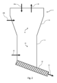
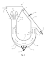
図1は、炭素質材料を変換するための反応器1の概略図である。反応器1は、固体粉末材料を収容するように構成された反応器室2を有する。反応器1は、下部10及び上部11を有し、反応器1の上部11に固体材料を供給するための固体材料入口20を備える。固体材料入口20は、図示のように側部又は頂部に配置されてもよい。固体材料入口20は、炭素質材料及び/又は粉末材料を反応器に入れるのに適する。
Figure 1 is a schematic diagram of a
ガス出口26は反応器1の上部11に配置され、固体材料出口21は反応器1の下部10に配置される。固体材料出口21は、反応器内での固体材料の高さ及び/又は量を調節するように構成された調節手段を備える。
The
反応器室2、並びに固体材料入口20、ガス出口26、及び固体材料出口21の位置は、ガス-固体分離ができるように配置される。特定の実施形態では、これは、上部11にガス出口、下部10に固体材料出口を有し、ガス出口でのガス流の速度が飛沫同伴速度より低くなるように、これらを、間隔を空けて異なる高さに配置することによって達成される。
The
意図する使用中、変換温度の炭素質材料が、炭素質材料の変換温度より高い温度の粉末材料とともに反応室2に加えられる。固体は、空気圧で反応器室2に運ばれてもよいし、機械的に供給されてもよい。図1では、粉末材料及び炭素質材料の両方が固体材料入口20を通して加えられるが、図2に示すように、異なる入口を通して加えられてもよい。反応器1は、反応器室2内の環境が、炭素をCO2に部分的にだけ酸化するように構成された状態で運転される。好ましくは、反応室内の全雰囲気に対する酸素の比率(ラムダ)は、0.15より低いことが好ましく、例えば0.12より低く、0.05が好ましく、0.03がより好ましい。
During intended use, carbonaceous material at a conversion temperature is added to the
炭素質材料と粉末材料は、接触しながら反応室2内を下方に落ちる。炭素質材料が変換温度以上に加熱されると、変換された材料及び揮発性生成物への炭素質材料の変換が起きる。変換された材料は、粉末材料及び未変換の炭素質材料とともに、反応室2の底部に向かってさらに落ちる。固体材料出口21の調節手段は、反応器室2の下部10にある固体材料の量を調節する。この調節は、固体材料の柱の所望の高さに従って、且つ/又は、炭素質材料を変換することができる所望の保持時間を得るように行うことができる。保持時間は少なくとも30秒とすべきであるが、炭素質燃料の仕様(タイプ、大きさ、変換温度など)に応じて、保持時間は少なくとも120秒、最長で約600秒としてもよい。
The carbonaceous material and the powdered material fall downward in the
炭素質材料から変換された揮発性物質は、固体の下向きの流れに逆らって、ガス出口26に向かって上向きに流れる。これは、固体間のより良い混合及び熱伝達を確実にする。反応器1の寸法は、ガス出口26のガス速度が飛沫同伴速度より低くなるように構成され、その結果、ガス出口26を通って運び出される固体はほとんど又は全くない。ガス速度は、反応器1内の温度を調節すること、保持時間を調節すること、又はガス入口25を通してガスを加えることによって制御することができる。
Volatiles converted from the carbonaceous material flow upwards towards the
次に、本発明の別の実施形態による反応器1を示す図2を参照する。この反応器は、下部10及び上部11を有する反応器室2を備える。反応器室2の流路面積は、反応器室2の断面寸法値(直径)を増大させることによって、反応器室2の上部11において増大する。揮発性物質が下部10から上部11に上向きに流れるとき、ガスの圧力、及び速度も、固体の飛沫同伴速度よりも低く下げられる。図示の実施形態では、反応器1は、ともに上部11に配置された2つの固体材料入口20a及び20bを有する。炭素質材料は、材料入口20aを通して反応器室2に加えることができ、これにより、炭素質材料は、固体材料入口20bを通って反応器室に入る粉末材料と接触する前に高温の揮発性物質と熱交換することができる。固体材料出口21は、送りねじ22に隣接して下部10に配置される。送りねじ22は、反応器室2の下部10から固体材料を機械的に輸送する。送りねじ22の回転速度は、反応器室2内の固体材料の高さを一定に保つように調節することができる。
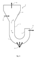
Reference is now made to FIG. 2, which shows a
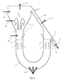
次に、本発明のさらに別の実施形態による反応器1を示す図3を参照すると、反応器1の下部10はU字形の形態の流体トラップ構成を有し、反応器1内の固体材料を調節するための手段は、流体を注入しそれによって粉末材料を流動化させるように構成された1つ又は複数の流体入口25である。反応器1は、断面で見て、2つの開口が上方に向けられた、本質的に半環状形を有する第1の導管5を備える。第1の導管の一端は、反応器室2の下部に流体的に接続されている。第2の導管6は、実質的に垂直方向に向けられ、その下端は第1の導管5の他端に流体的に取り付けられている。流体入口25は、第1の導管5の底部に配置される。流体入口25を通して流体を注入し、反応器1内の粉末材料を流動化させることにより、反応器1内の粉末の量を決めるのは、固体材料出口21の位置とともに反応器室2及び第2の導管6内の材料の柱の重量である。上部11の少なくとも一部の直径は、反応器室2の頂部に向かって徐々に増大して円錐形部分15を提供する。これにより、反応器室内の流路面積は徐々に増大する。流路面積の増大は、急激な増大であってもよいと言える。
3, which shows a
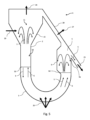
次に、図4を参照して、炭素質材料を変換する方法及び反応器1内の流路をより詳細に説明する。図4には、反応器室2の上部11を第2の導管6の上端と流体的に接続するバイパス導管28を備える反応器1が示されている。ガス出口27は、バイパス導管28に配置される。
The method of converting carbonaceous materials and the flow paths within the
意図する使用中、炭素質材料及び粉末材料は、固体材料入口20a、20b、及び/又は20cを通して反応器室2に加えられる。炭素質材料の温度は変換温度であり、粉末材料の温度は変換温度よりも高い。反応器室2に加えられると、炭素質材料と粉末材料とが接触し、炭素質材料が変換された材料と揮発性生成物とに変換し始める。反応器室2内の雰囲気は、炭素をCO2に部分的にだけ酸化するように構成されている。使用中、固体(すなわち、炭素質材料、粉末材料、及び変換された材料)は、重力により上部11から下部10に向かって落ち、第1の導管5を満たす。流体入口25を通してガスを注入することにより、固体は流動化され、反応器室2の下部10と、第1の導管5と、第2の導管6との間で分配される。点線50は、反応器室2及び第2の導管6内の流動化された固体の柱が同じ密度を有する、すなわちそれらが同じ高さである状態での固体の柱の高さを示す。点線50の下では、固体は高密度な相で存在する。導管6の上縁51は、導管6内の流動化された固体の柱の高さを決め、それによって、反応器室2の下部10の流動化された固体の柱の高さも決める。固体が高さ50よりもさらに堆積すると、固体は、プラグフロー型のパターンで第1の導管5及び第2の導管6を通って上縁51を越えて流れ、流動化された固体の2つの柱の重量間でのバランスを調節する。固体の流れ方向は、「S」の矢印で示されている。揮発性物質及び変換された材料への炭素質材料の変換は、反応室2、第1導管5、及び第2の導管6の両方で起きる。揮発性物質と流動化ガスの流れ方向は、(G)の矢印で示されている。揮発性物質の発生により、反応器室2の下部10における上向きのガス流の速度は、典型的には、固体の飛沫同伴速度よりも高い。したがって、固体は、ガスによって捉えられ、反応器室2の上部11に向かって上方に持ち上げられ、反応器室内に低濃度の固体の領域、すなわち希薄な区域を形成する。この区域は、点線50の上方に位置する。ガス及び固体が円錐形部分15に達すると、速度は飛沫同伴速度よりも低下し、固体はもはやガスによって浮遊することができない。これは、固体が再び反応器室2の下部10に向かって下方に落ち、ガスが実質的に固体を含まずに上がり続ける噴出区域を提供する。この固体の流れは噴水に類似しており、反応器室2の上部11に矢印「S」で示されている。運転中、固体は、「S」の矢印によって示されるように、いくつかの方向に流れるが、全体の物質収支の観点から見ると、固体は上部11から下部10、第1の導管5、及び第2の導管6を通って移動する。
During intended use, the carbonaceous material and powdered material are added to the
第2の導管6内で発生したすべての揮発性物質は、固体とともに上向きに流れる。固体とガスの流れが上縁51を通過すると、実質的にすべての固体は固体材料出口21を通って流れ、一方、ガスはガス出口26及び/又は27に向かってバイパス導管28を通って上がり続ける。
Any volatiles generated in the
流体入口25を通して供給されるガスは、より少ないガス量でより効率的に流動化させるパルス状で供給されることが好ましい。このガスは、反応ガス、不活性ガス、又はそれらの組合せを含んでもよい。
The gas supplied through the
次に、さらに別の実施形態による反応器1を示す図5を参照すると、第2の導管6の流路面積は増大している。流路面積の増大は、第2の導管内のすべてガス流の速度が固体の飛沫同伴速度より低くまで下げることができるように、徐々に増大しても、急激に増大してもよい。図5に示す実施形態は2つの噴出区域を有する。これは、反応器室2では炭素質材料の部分的な変換だけが起こり、多くの変換が第1の導管5、又は第2の導管6でさえ起こることがあるときに有益である。第2の導管6が、発生した揮発性物質を収めるような適切な大きさでない場合、揮発性物質の発生の結果、固体の飛沫同伴速度を超えるガス速度が生じることがある。この結果、第2の導管6内の高密度な相が希薄になり、ガス出口27への揮発性物質及び固体の流れを含む望ましくないフローパターンが生じる。第2の導管6の一部分の断面寸法を増大させて、増大した流路面積を有する部分を提供することにより、同伴された粉末が落ち、最終的に固体材料出口21に向かって縁51を越えてこぼれる噴出及び沈降区域が確立される。この結果、反応器室2から出口21への安定した固体流れが生じ、それによって、プロセス全体の動作が著しく改善され、第2の導管6の大きさをより小さくすることができる。反応器1が容易に変換可能な炭素質材料で運転される場合、揮発性物質の発生は本質的に反応器室2で起こる。このような状況では、図4の実施形態が、安定した運転のためには十分な場合がある。反応器1がより大きな炭素質材料片又は変換しにくい炭素質材料で運転される場合、揮発性物質の発生は反応器全体、又は主に第2の導管でさえ起こることがある。この状況では、第2の導管、又は反応器室2と第2の導管6との両方の噴出区域及び沈降区域が、反応器1の安定した運転のために有益である。
Now referring to FIG. 5, which shows a
次に、さらに別の実施形態による反応器1を示す図6を参照すると、第1の導管5は、いわゆる拡張半径設計を有している。上部導管壁32と下部導管壁31との間の断面積値(すなわち、距離)が、第1の導管5を通して変化していることが分かる。網30が、任意選択で、上部導管壁32から一定の距離で第1の導管5内に配置される。これにより、網30の下方に固体のない空隙35が設けられる。網により、固体が下部導管壁31と直接接触しないことが確実になる。反応ガスが流体入口25を通して供給されると、炭素質材料の酸化により局所的な温度上昇が見られることがある。網30は、例えば、塩化物及び/又は硫黄を含む代替燃料で焼成するときに予想することができる材料の堆積又は高温腐食によって、下部導管壁31が高温によって損傷されないことを確実にする。網30は、第1の導管5と比較して、容易に交換可能である。
Now referring to FIG. 6, which shows a
図5に示す反応器1は、ガス出口27だけしかない。したがって、反応器室2からの揮発性物質及び反応ガスは、反応物室2の上部11からバイパス導管28を通ってガス出口27に向かって流れる。
The
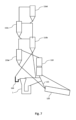
次に、セメントクリンカー製造プラントの予熱タワー100、か焼炉110、及びキルン120と接続されて設置された反応器1を示す図7を参照する。キルン120とか焼炉110は、キルンライザー115によって接続される。セメント原料ミールは、最上段の予熱器サイクロン150dの原料ミール入口に供給される。その点から、原料ミールは、ロータリーキルン120からの高温の排気ガスに対して対向流で、予熱器のサイクロン及びか焼炉110を通ってロータリーキルン120に向かって流れ、それによって原料ミールを加熱し、か焼する。か焼されたミールは、か焼炉110から最下段のサイクロン150aに導かれ、ここで、か焼されたミールは、か焼炉の排気ガスから分離される。か焼された原料ミールはロータリーキルン120で焼成されてセメントクリンカーとなり、セメントクリンカーは後続のクリンカークーラーで大気によって冷却される(図示せず)。このようにして加熱された空気の一部は、クリンカークーラーからダクトを通って、いわゆる三次空気としてか焼炉110に導かれる(図示せず)。
Reference is now made to FIG. 7, which shows the
反応器1は、か焼炉110及びキルンライザー115に隣接して配置され、任意選択で、高温のセメントミールがサイクロン段150bから重力によって移動するように配置される。150bからの高温のセメントミールは、0~100%の間の調節可能な比率で、反応器1と、キルンライザー115と、か焼炉110との間で分けられる。反応器1に向けられる高温のセメントミールの量は、代替燃料の入力速度と変換時間に依存する。高温のセメントミールの残りは、キルンライザー115とか焼炉110との間で分けられる。典型的には、高温のセメントミールの50~70%がか焼炉110に導かれ、残りの大部分は反応器1に送られる。サイクロン150bからの高温のセメントミールの温度は、典型的には、730~830℃の範囲となる。150bからの高温のセメントミールは、本質的に変換生成物が150bに流入すること、及び150bからのガスが反応器1に流入することを防止するガスバリアとして機能するループシール130を優先的に通過する。
未変換の代替燃料及び高温のセメントミールは、パイロシステムに、最も好ましくはキルンライザー115を通ってか焼炉110に導かれる。反応器1からの変換生成物の一部又は全部は、キルンライザー115に導入されて、キルン120で生成されたNOxを還元するために還元区域を生成することができる、又はか焼炉110に直接導入することができる。別の実施形態では、反応器1からの変換生成物すなわち揮発性ガスの一部又は全部は、ロータリーキルンバーナーで利用することができる。さらなる実施形態では、変換生成物ガスの一部又は全部は、可燃性ガスを作るプロセスなど、セメントプロセスの外部で利用することができる。
The unconverted alternative fuel and hot cement meal are directed to the Pyro system, most preferably through a
これに代えて、高温のセメントミールは、150c又は150aなどの予熱器の他のサイクロンから反応器1に向けることができる。高温のセメントミールは、任意選択で、反応器1の材料入口へのガスバリアとして機能するループシール130を通過させられる。ループシールの底は、任意選択で、特大粒子のための底部出口を備えてもよく、この出口は、キルンライザー115、キルン入口、又は別個の容器に接続されてもよい。
Alternatively, the hot cement meal can be directed to
予熱器は、個々のサイクロン間でガス及び固体を完全又は部分的に分けるサイクロンの数を変えた多数の構成で設計することができる。いくつかの場合には、か焼炉110における所望のプロセス状態を得るために、他のサイクロンからの固体の一部又はその混合物をとることが好ましい場合がある。
The preheater can be designed in a number of configurations with varying numbers of cyclones that completely or partially separate the gases and solids between the individual cyclones. In some cases, it may be preferable to take a portion or a mixture of solids from other cyclones to obtain the desired process conditions in the
図6に描かれたか焼炉110の構成は、か焼炉が、キルン排気ガスのすべてがか焼炉110を通過するようにキルンライザー115に対して配置されたいわゆる「インラインか焼炉」システムである。本発明の方法はまた、キルン燃焼ガスがか焼炉を通過しないようにか焼室がキルンライザー115から少なくとも部分的にずらされており、か焼炉用の燃焼空気が別の三次空気ダクトを通って引き込まれる「別ラインか焼炉」システムを含む他の構成でも有効に使用することができる。
The
Claims (18)
固体炭素質材料及び粉末材料を前記反応器に供給するための少なくとも1つの固体材料入口と、
変換された炭素質材料及び/又は粉末材料を取り出すことができるように構成された少なくとも1つの固体材料出口であって、前記反応器内の固体材料の高さ又は量を調節するように構成された調節手段を備える、少なくとも1つの固体材料出口と、
粉末材料を流動化させるように構成された流動化手段と、
ガス出口と、
ガスを固体材料から分離するように構成されたガス-固体分離手段であって、前記反応器の前記下部よりも大きな流路面積を有する、前記反応器の前記上部の一部分であり、垂直方向の流れにおいてガスと固体を分離し、前記ガスの速度を前記固体の飛沫同伴速度より低くまで下げるように構成された、ガス-固体分離手段とを備え、
前記炭素質材料の前記変換が、前記炭素質材料が、加熱された前記粉末材料と接触し、加熱された前記粉末材料によって加熱されると起きるように構成され、
前記少なくとも1つの固体材料入口が、前記炭素質材料が前記反応器の、より大きな前記流路面積を有する前記一部分に提供されるように前記反応器の上部に配置された、炭素質材料を変換するための反応器。 1. A reactor for converting a carbonaceous material, the reactor being configured to accommodate a solid powdered material and having an upper portion and a lower portion;
at least one solid material inlet for supplying solid carbonaceous material and powdered material to said reactor;
at least one solid material outlet configured to be able to remove the converted carbonaceous material and/or powder material, the at least one solid material outlet comprising an adjustment means configured to adjust the height or amount of solid material in the reactor;
a fluidizing means configured to fluidize the powder material;
A gas outlet;
a gas-solids separation means configured to separate gas from solid material, the gas-solids separation means being a portion of the upper portion of the reactor having a larger flow area than the lower portion of the reactor, the gas-solids separation means being configured to separate gas and solids in a vertical flow and to reduce the velocity of the gas below the entrainment velocity of the solids;
wherein the converting of the carbonaceous material occurs when the carbonaceous material contacts and is heated by the heated powder material;
1. A reactor for converting a carbonaceous material, wherein the at least one solid material inlet is disposed at an upper portion of the reactor such that the carbonaceous material is provided to the portion of the reactor having the larger flow area.
前記第1の導管が、前記第1の導管の長さを通して断面寸法値を変えることによって前記上部導管壁と前記下部導管壁の間に固体の保護層を設けるように構成された、請求項4に記載の炭素質材料を変換するための反応器。 the first conduit includes an upper conduit wall and a lower conduit wall configured for the powder material to flow between the upper conduit wall and the lower conduit wall;
5. The reactor for converting carbonaceous materials as described in claim 4, wherein the first conduit is configured to provide a solid protective layer between the upper conduit wall and the lower conduit wall by varying a cross-sectional dimension throughout the length of the first conduit.
前記少なくとも1つの固体材料入口を介して前記炭素質材料の前記変換温度よりも高い温度を有する粉末材料を供給するステップと、
炭素をCO2に部分的にだけ酸化するように構成された雰囲気中で前記炭素質材料と前記粉末材料とを接触させて、前記炭素質材料を、変換された材料と揮発性生成物とに少なくとも部分的に変換するステップと、
前記炭素質材料及び加熱された前記粉末材料を流動化させるステップと、
前記反応器の下部よりも大きな流路面積を有する、前記反応器の上部の一部分であるガス-固体分離手段により、前記揮発性生成物を含むガス流を上方向に向けることによって比重により分離して、前記揮発性生成物を含む部分と、追加成分を含む第2の部分とを提供するステップであって、前記追加成分が、前記粉末材料、変換された材料、及び、任意選択で、変換されなかった又は部分的に変換された炭素質材料である、ステップと、
固体材料出口を通して前記第2の部分を取り出して、流動化された固体材料の高さを調節するステップとを含み、
前記炭素質材料と前記粉末材料との間の前記接触が、少なくとも2つの異なる流れ形態で起き、
前記炭素質材料の前記変換が、前記炭素質材料が、加熱された前記粉末材料と接触し、加熱された前記粉末材料によって加熱されると起き、
前記少なくとも1つの固体材料入口が、前記炭素質材料が前記反応器の、より大きな前記流路面積を有する前記一部分に提供されるように前記反応器の前記上部に配置された、炭素質材料の変換のための方法。 providing a carbonaceous material having a conversion temperature via at least one solid material inlet of the reactor;
supplying a powder material having a temperature higher than the conversion temperature of the carbonaceous material via the at least one solid material inlet;
contacting the carbonaceous material with the powdered material in an atmosphere configured to only partially oxidize carbon to CO2 to at least partially convert the carbonaceous material into a converted material and a volatile product;
fluidizing the carbonaceous material and the heated powder material;
gravitationally separating the gas stream comprising the volatile products by directing it upward through a gas-solid separation means, which is a portion of an upper portion of the reactor having a larger flow area than a lower portion of the reactor, to provide a portion comprising the volatile products and a second portion comprising additional components, the additional components being the powder material, the converted material, and optionally unconverted or partially converted carbonaceous material;
and removing the second portion through a solid material outlet to adjust the height of the fluidized solid material.
the contact between the carbonaceous material and the powder material occurs in at least two different flow regimes;
the converting of the carbonaceous material occurs when the carbonaceous material contacts and is heated by the heated powder material;
16. A method for converting carbonaceous material, wherein the at least one solid material inlet is disposed at an upper portion of the reactor such that the carbonaceous material is provided to the portion of the reactor having the larger flow area.
任意選択で、前記前駆物質を加熱して前記反応ガスを発生させるステップと、
前記反応ガスを、加熱された前記粉末材料と前記炭素質材料との混合物と接触させるステップと
をさらに含む、請求項9~11のいずれか一項に記載の炭素質材料の変換のための方法。 Providing a reactive gas, or optionally a precursor for the reactive gas, in an atmosphere configured to only partially oxidize carbon to CO2 ;
Optionally, heating the precursor to generate the reactant gas;
A method for the conversion of carbonaceous materials according to any one of claims 9 to 11, further comprising the step of contacting the reaction gas with the heated mixture of the powdered material and the carbonaceous material.
Applications Claiming Priority (3)
| Application Number | Priority Date | Filing Date | Title |
|---|---|---|---|
| DKPA202000392 | 2020-04-03 | ||
| DKPA202000392 | 2020-04-03 | ||
| PCT/EP2021/058478 WO2021198358A1 (en) | 2020-04-03 | 2021-03-31 | Reactor and method for conversion of a carbonaceous material |
Publications (2)
| Publication Number | Publication Date |
|---|---|
| JP2023520042A JP2023520042A (en) | 2023-05-15 |
| JP7581365B2 true JP7581365B2 (en) | 2024-11-12 |
Family
ID=75438739
Family Applications (1)
| Application Number | Title | Priority Date | Filing Date |
|---|---|---|---|
| JP2022559867A Active JP7581365B2 (en) | 2020-04-03 | 2021-03-31 | Reactor and method for the conversion of carbonaceous materials - Patents.com |
Country Status (11)
| Country | Link |
|---|---|
| US (1) | US20230173448A1 (en) |
| EP (1) | EP4126328B1 (en) |
| JP (1) | JP7581365B2 (en) |
| KR (1) | KR102848061B1 (en) |
| CN (1) | CN115485059A (en) |
| BR (1) | BR112022020035A2 (en) |
| DK (1) | DK4126328T3 (en) |
| ES (1) | ES2967540T3 (en) |
| MX (1) | MX2022012292A (en) |
| PL (1) | PL4126328T3 (en) |
| WO (1) | WO2021198358A1 (en) |
Citations (3)
| Publication number | Priority date | Publication date | Assignee | Title |
|---|---|---|---|---|
| JP2010521282A (en) | 2007-03-16 | 2010-06-24 | オウトテック オサケイティオ ユルキネン | Method for enhancing purification in mixed reactor and mixed reactor |
| JP2015131869A (en) | 2014-01-09 | 2015-07-23 | 新日鐵住金株式会社 | Coke oven fastening structure and fastening method |
| WO2017125579A1 (en) | 2016-01-22 | 2017-07-27 | Flsmidth A/S | U-shaped combustor and method for use in cement plants |
Family Cites Families (16)
| Publication number | Priority date | Publication date | Assignee | Title |
|---|---|---|---|---|
| US3086852A (en) * | 1958-03-27 | 1963-04-23 | Exxon Research Engineering Co | Reactor for vapor phase catalytic conversion |
| GB1428680A (en) * | 1972-12-11 | 1976-03-17 | Smidth & Co As F L | Calcination of pulverous material |
| JPS60636Y2 (en) * | 1980-12-23 | 1985-01-09 | 石川島播磨重工業株式会社 | Spouted bed type fluidized furnace |
| JPS57165028A (en) * | 1981-04-06 | 1982-10-09 | Kawasaki Heavy Ind Ltd | Method and apparatus for baking cement clinker or the like |
| JPS61270241A (en) * | 1985-05-22 | 1986-11-29 | 川崎重工業株式会社 | Fluidized burning method for cement clinker |
| FI87147C (en) * | 1990-07-13 | 1992-12-10 | Ahlstroem Oy | REFRIGERATOR OIL BEHANDLING AV GASER OCH / ELLER FAST MATERIAL I EN REACTOR WITH CIRCULAR FLUIDISERAD BAEDD |
| US9504975B2 (en) * | 2004-03-23 | 2016-11-29 | W. R. Grace & Co.-Conn. | System and process for injecting catalyst and/or additives into a fluidized catalytic cracking unit |
| US8603222B2 (en) * | 2005-10-21 | 2013-12-10 | Calix Ltd. | System and method for calcination/carbonation cycle processing |
| CN201046951Y (en) * | 2006-12-08 | 2008-04-16 | 孙佰仲 | Oil shale refining furnace dry method decoking apparatus |
| EP2153154A1 (en) * | 2007-06-12 | 2010-02-17 | FLSmidth A/S | Method and plant for the simultaneous production of electricity and cement clinker |
| AU2008265954A1 (en) * | 2007-06-13 | 2008-12-24 | Wormser Energy Solutions, Inc. | Mild gasification combined-cycle powerplant |
| US8916735B2 (en) * | 2011-08-13 | 2014-12-23 | Mcalister Technologies, Llc | Carbon-based durable goods and renewable fuel from biomass waste dissociation for transportation and storage |
| CN104178228B (en) * | 2013-05-23 | 2016-08-17 | 中石化洛阳工程有限公司 | A kind of fluidized bed dry distillation method and apparatus of coal dust |
| WO2018053110A1 (en) * | 2016-09-16 | 2018-03-22 | Lummus Technology Inc. | Fluid catalytic cracking process and apparatus for maximizing light olefin yield and other applications |
| US10758883B2 (en) * | 2016-09-16 | 2020-09-01 | Lummus Technology Llc | Fluid catalytic cracking process and apparatus for maximizing light olefin yield and other applications |
| CN106753584A (en) * | 2016-12-27 | 2017-05-31 | 广东国能中林实业有限公司 | A kind of fluidized bed pyrolysis gasification installation of use biological fuel gas recirculating process |
-
2021
- 2021-03-31 DK DK21717359.0T patent/DK4126328T3/en active
- 2021-03-31 PL PL21717359.0T patent/PL4126328T3/en unknown
- 2021-03-31 WO PCT/EP2021/058478 patent/WO2021198358A1/en not_active Ceased
- 2021-03-31 BR BR112022020035A patent/BR112022020035A2/en unknown
- 2021-03-31 JP JP2022559867A patent/JP7581365B2/en active Active
- 2021-03-31 US US17/916,566 patent/US20230173448A1/en active Pending
- 2021-03-31 EP EP21717359.0A patent/EP4126328B1/en active Active
- 2021-03-31 CN CN202180032816.0A patent/CN115485059A/en active Pending
- 2021-03-31 KR KR1020227038046A patent/KR102848061B1/en active Active
- 2021-03-31 ES ES21717359T patent/ES2967540T3/en active Active
- 2021-03-31 MX MX2022012292A patent/MX2022012292A/en unknown
Patent Citations (3)
| Publication number | Priority date | Publication date | Assignee | Title |
|---|---|---|---|---|
| JP2010521282A (en) | 2007-03-16 | 2010-06-24 | オウトテック オサケイティオ ユルキネン | Method for enhancing purification in mixed reactor and mixed reactor |
| JP2015131869A (en) | 2014-01-09 | 2015-07-23 | 新日鐵住金株式会社 | Coke oven fastening structure and fastening method |
| WO2017125579A1 (en) | 2016-01-22 | 2017-07-27 | Flsmidth A/S | U-shaped combustor and method for use in cement plants |
Also Published As
| Publication number | Publication date |
|---|---|
| KR20220155606A (en) | 2022-11-23 |
| MX2022012292A (en) | 2022-10-27 |
| WO2021198358A1 (en) | 2021-10-07 |
| EP4126328B1 (en) | 2023-11-08 |
| EP4126328A1 (en) | 2023-02-08 |
| KR102848061B1 (en) | 2025-08-22 |
| DK4126328T3 (en) | 2023-12-18 |
| CN115485059A (en) | 2022-12-16 |
| ES2967540T3 (en) | 2024-04-30 |
| BR112022020035A2 (en) | 2022-11-22 |
| PL4126328T3 (en) | 2024-04-08 |
| JP2023520042A (en) | 2023-05-15 |
| US20230173448A1 (en) | 2023-06-08 |
Similar Documents
| Publication | Publication Date | Title |
|---|---|---|
| US9726369B2 (en) | Chemical-looping combustion method with ashes and fines removal in the reduction zone and plant using same | |
| US4969930A (en) | Process for gasifying or combusting solid carbonaceous material | |
| US5154732A (en) | Apparatus for gasifying or combusting solid carbonaceous | |
| RU2520487C2 (en) | Circulating fluidised bed reactor with improved circulation | |
| US3890111A (en) | Transfer line burner system using low oxygen content gas | |
| AU2009256101B2 (en) | Fluidized bed gasifier with solids discharge and classification device | |
| KR101966578B1 (en) | Chemical Roofing Combustion Process with Gravity Feed of Oxidized Particles and Various Fuel Reaction Zones | |
| CA2660925C (en) | A method for performing pyrolysis and a pyrolysis apparatus | |
| JP7601765B2 (en) | Gasification reactor and gasification method | |
| CN101646486B (en) | Method and apparatus for controlling the temperature of a fluidized bed reactor | |
| US3935825A (en) | Coal ash agglomeration device | |
| EP1841519B1 (en) | Method for pyrolysis/gasification of biomass in a plant with dipleg | |
| WO1986001821A1 (en) | Gasification apparatus | |
| EP0050863A1 (en) | Process of and apparatus for gasifying coals | |
| EA010277B1 (en) | Method and plant for producing low-temperature coke | |
| US3874739A (en) | Method and apparatus for the transfer of entrained solids | |
| JP7581365B2 (en) | Reactor and method for the conversion of carbonaceous materials - Patents.com | |
| JPS63501511A (en) | Low inlet gas rate and high throughput biomass gasifier | |
| KR100460217B1 (en) | Coal Gasifier using Downer Region in a Circulating Fluidized Bed Reactor | |
| CN1106131A (en) | Combustion of liquid and gaseous fuels in circulating fluidized bed reactors | |
| CN119196666B (en) | Combustion unit and dual fluidized bed reactor using the combustion unit | |
| RU2829149C1 (en) | In-line gasifier for low-grade fuel | |
| JPS6045935B2 (en) | Fluidized bed pyrolysis gasification method and device that circulates powder using an inner cylinder with a partition plate | |
| CA2151893A1 (en) | Apparatus for separating solid particles from a gas and for injecting the so-separated particles into a reaction vessel | |
| CN117660061A (en) | Return unit and double fluidized bed reaction device using this unit |
Legal Events
| Date | Code | Title | Description |
|---|---|---|---|
| A521 | Request for written amendment filed |
Free format text: JAPANESE INTERMEDIATE CODE: A523 Effective date: 20221201 |
|
| A621 | Written request for application examination |
Free format text: JAPANESE INTERMEDIATE CODE: A621 Effective date: 20221228 |
|
| A977 | Report on retrieval |
Free format text: JAPANESE INTERMEDIATE CODE: A971007 Effective date: 20231213 |
|
| A131 | Notification of reasons for refusal |
Free format text: JAPANESE INTERMEDIATE CODE: A131 Effective date: 20240122 |
|
| A521 | Request for written amendment filed |
Free format text: JAPANESE INTERMEDIATE CODE: A523 Effective date: 20240402 |
|
| A131 | Notification of reasons for refusal |
Free format text: JAPANESE INTERMEDIATE CODE: A131 Effective date: 20240723 |
|
| A521 | Request for written amendment filed |
Free format text: JAPANESE INTERMEDIATE CODE: A523 Effective date: 20240801 |
|
| TRDD | Decision of grant or rejection written | ||
| A01 | Written decision to grant a patent or to grant a registration (utility model) |
Free format text: JAPANESE INTERMEDIATE CODE: A01 Effective date: 20241001 |
|
| A61 | First payment of annual fees (during grant procedure) |
Free format text: JAPANESE INTERMEDIATE CODE: A61 Effective date: 20241030 |
|
| R150 | Certificate of patent or registration of utility model |
Ref document number: 7581365 Country of ref document: JP Free format text: JAPANESE INTERMEDIATE CODE: R150 |
|
| S111 | Request for change of ownership or part of ownership |
Free format text: JAPANESE INTERMEDIATE CODE: R313113 |
|
| R350 | Written notification of registration of transfer |
Free format text: JAPANESE INTERMEDIATE CODE: R350 |
|
| S531 | Written request for registration of change of domicile |
Free format text: JAPANESE INTERMEDIATE CODE: R313531 |
|
| S533 | Written request for registration of change of name |
Free format text: JAPANESE INTERMEDIATE CODE: R313533 |
|
| R350 | Written notification of registration of transfer |
Free format text: JAPANESE INTERMEDIATE CODE: R350 |