JP7581339B2 - METHOD FOR TRANSMITTING AND RECEIVING SIGNAL IN WIRELESS COMMUNICATION SYSTEM AND APPARATUS SUPPORTING THE SAME - Google Patents
METHOD FOR TRANSMITTING AND RECEIVING SIGNAL IN WIRELESS COMMUNICATION SYSTEM AND APPARATUS SUPPORTING THE SAME Download PDFInfo
- Publication number
- JP7581339B2 JP7581339B2 JP2022520607A JP2022520607A JP7581339B2 JP 7581339 B2 JP7581339 B2 JP 7581339B2 JP 2022520607 A JP2022520607 A JP 2022520607A JP 2022520607 A JP2022520607 A JP 2022520607A JP 7581339 B2 JP7581339 B2 JP 7581339B2
- Authority
- JP
- Japan
- Prior art keywords
- pusch
- prach
- various embodiments
- message
- valid
- Prior art date
- Legal status (The legal status is an assumption and is not a legal conclusion. Google has not performed a legal analysis and makes no representation as to the accuracy of the status listed.)
- Active
Links
Images
Classifications
-
- H—ELECTRICITY
- H04—ELECTRIC COMMUNICATION TECHNIQUE
- H04W—WIRELESS COMMUNICATION NETWORKS
- H04W74/00—Wireless channel access
- H04W74/08—Non-scheduled access, e.g. ALOHA
- H04W74/0833—Random access procedures, e.g. with 4-step access
-
- H—ELECTRICITY
- H04—ELECTRIC COMMUNICATION TECHNIQUE
- H04L—TRANSMISSION OF DIGITAL INFORMATION, e.g. TELEGRAPHIC COMMUNICATION
- H04L5/00—Arrangements affording multiple use of the transmission path
- H04L5/003—Arrangements for allocating sub-channels of the transmission path
- H04L5/0044—Allocation of payload; Allocation of data channels, e.g. PDSCH or PUSCH
-
- H—ELECTRICITY
- H04—ELECTRIC COMMUNICATION TECHNIQUE
- H04W—WIRELESS COMMUNICATION NETWORKS
- H04W72/00—Local resource management
- H04W72/12—Wireless traffic scheduling
- H04W72/1263—Mapping of traffic onto schedule, e.g. scheduled allocation or multiplexing of flows
- H04W72/1268—Mapping of traffic onto schedule, e.g. scheduled allocation or multiplexing of flows of uplink data flows
-
- H—ELECTRICITY
- H04—ELECTRIC COMMUNICATION TECHNIQUE
- H04W—WIRELESS COMMUNICATION NETWORKS
- H04W74/00—Wireless channel access
- H04W74/002—Transmission of channel access control information
- H04W74/004—Transmission of channel access control information in the uplink, i.e. towards network
-
- H—ELECTRICITY
- H04—ELECTRIC COMMUNICATION TECHNIQUE
- H04W—WIRELESS COMMUNICATION NETWORKS
- H04W74/00—Wireless channel access
- H04W74/08—Non-scheduled access, e.g. ALOHA
- H04W74/0833—Random access procedures, e.g. with 4-step access
- H04W74/0836—Random access procedures, e.g. with 4-step access with 2-step access
-
- H—ELECTRICITY
- H04—ELECTRIC COMMUNICATION TECHNIQUE
- H04W—WIRELESS COMMUNICATION NETWORKS
- H04W74/00—Wireless channel access
- H04W74/08—Non-scheduled access, e.g. ALOHA
- H04W74/0833—Random access procedures, e.g. with 4-step access
- H04W74/0838—Random access procedures, e.g. with 4-step access using contention-free random access [CFRA]
Landscapes
- Engineering & Computer Science (AREA)
- Signal Processing (AREA)
- Computer Networks & Wireless Communication (AREA)
- Mobile Radio Communication Systems (AREA)
Description
様々な実施例は無線通信システムに関する。 Various embodiments relate to wireless communication systems.
無線接続システムが音声やデータなどの種々の通信サービスを提供するために広範囲に展開されている。一般に、無線接続システムは可用のシステムリソース(帯域幅、送信電力など)を共有して複数のユーザとの通信を支援できる多重接続(multiple access)システムである。多重接続システムの例には、CDMA(code division multiple access)システム、FDMA(frequency division multiple access)システム、TDMA(time division multiple access)システム、OFDMA(orthogonal frequency division multiple access)システム、SC-FDMA(single carrier frequency division multiple access)システムなどがある。 Wireless access systems are widely deployed to provide various communication services such as voice and data. Generally, wireless access systems are multiple access systems that can support communication with multiple users by sharing available system resources (bandwidth, transmit power, etc.). Examples of multiple access systems include code division multiple access (CDMA) systems, frequency division multiple access (FDMA) systems, time division multiple access (TDMA) systems, orthogonal frequency division multiple access (OFDMA) systems, and single carrier frequency division multiple access (SC-FDMA) systems.
様々な実施例は無線通信システムにおいて信号を送受信する方法及びそれを支援する装置を提供する。 Various embodiments provide methods and devices for supporting same for transmitting and receiving signals in a wireless communication system.
様々な実施例は無線通信システムにおいて2-ステップRACH手順のための方法及びそれを支援する装置を提供する。 Various embodiments provide a method and apparatus for supporting a two-step RACH procedure in a wireless communication system.
様々な実施例は無線通信システムにおいてメッセージA PUSCH DMRSの設定方法及びそれを支援する装置を提供する。 Various embodiments provide a method and an apparatus for supporting a message A PUSCH DMRS configuration method in a wireless communication system.
様々な実施例は無線通信システムにおいてプリアンブルのPUSCH機会へのマッピング方法及びそれを支援する装置を提供する。 Various embodiments provide a method and an apparatus for supporting a method for mapping a preamble to a PUSCH opportunity in a wireless communication system.
本発明で遂げようとする技術的目的は、以上で言及した事項に制限されず、言及していない他の技術的課題は、以下に説明する本発明の実施例から、本発明の属する技術の分野における通常の知識を有する者にとって考慮されてもよい。 The technical objectives to be achieved by the present invention are not limited to those mentioned above, and other technical problems not mentioned may be considered by a person having ordinary skill in the technical field to which the present invention pertains from the embodiments of the present invention described below.
様々な実施例は無線通信システムにおいて信号を送受信する方法及びそれを支援する装置を提供する。 Various embodiments provide methods and devices for supporting same for transmitting and receiving signals in a wireless communication system.
様々な実施例によれば、無線通信システムにおいて端末が行う方法が提供される。 According to various embodiments, a method is provided that is performed by a terminal in a wireless communication system.
様々な実施例によれば、上記方法は:PRACH(physical random access channel)スロット内の複数の有効な(valid)PRACH機会(occasion)のうちのいずれかの有効なPRACH機会内でPRACHプリアンブル(preamble)を送信する過程;及びPRACHプリアンブルに対する応答として、RAR(random access response)に関連する情報を得る過程を含む。 According to various embodiments, the method includes: transmitting a PRACH preamble within a valid PRACH opportunity among a plurality of valid PRACH opportunities within a PRACH slot; and obtaining information related to a random access response (RAR) in response to the PRACH preamble.
様々な実施例によれば、PRACHプリアンブルは、複数の有効なPRACH機会に関連する複数のPRACHプリアンブルに含まれる。 According to various embodiments, the PRACH preamble is included in multiple PRACH preambles associated with multiple valid PRACH opportunities.
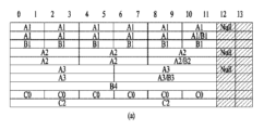
様々な実施例によれば、複数のPRACHプリアンブルに含まれた複数の連続するPRACHプリアンブルが一つの有効なPUSCH(physical uplink shared channel)機会にマッピングされることに基づいて、複数のPRACHプリアンブルは複数の有効なPUSCH機会のうち、第1PUSCH機会にマッピングされる。 According to various embodiments, the multiple PRACH preambles are mapped to a first PUSCH opportunity among the multiple valid PUSCH opportunities, based on the fact that multiple consecutive PRACH preambles included in the multiple PRACH preambles are mapped to one valid PUSCH opportunity.
様々な実施例によれば、第1PUSCH機会のうちのいずれかにおいて任意接続手順(random access procedure)に関連するPUSCHが送信される。 According to various embodiments, a PUSCH associated with a random access procedure is transmitted during one of the first PUSCH opportunities.
様々な実施例によれば、複数の有効なPUSCH機会のうち、第1PUSCH機会を除いた残りの第2PUSCH機会は任意接続手順に関連するPUSCHの送信に使用されない。 According to various embodiments, among the multiple available PUSCH opportunities, the remaining second PUSCH opportunities, excluding the first PUSCH opportunity, are not used to transmit PUSCH related to the optional connection procedure.
様々な実施例によれば、複数のPUSCH機会のうち、(i)UL(uplink)シンボルに含まれるか、又は(ii)最後の(last)DL(downlink)シンボルの後、少なくともNシンボル後に始まるPUSCH機会が複数の有効なPUSCH機会として決定され、Nは0以上の整数である。 According to various embodiments, among the multiple PUSCH opportunities, the multiple valid PUSCH opportunities are determined to be PUSCH opportunities that (i) are included in an UL (uplink) symbol or (ii) begin at least N symbols after the last DL (downlink) symbol, where N is an integer equal to or greater than 0.
様々な実施例によれば、複数のPRACHプリアンブルに含まれないPRACHプリアンブルに関連する有効なPRACH機会がPUSCH機会にマッピングされないことに基づいて、複数のPRACHプリアンブルに含まれないPRACHプリアンブルは、複数のPRACHプリアンブルに含まれないPRACHプリアンブルに関連する有効なPRACH機会に送信可能である。 According to various embodiments, a PRACH preamble that is not included in the plurality of PRACH preambles can be transmitted on a valid PRACH opportunity associated with a PRACH preamble that is not included in the plurality of PRACH preambles based on the valid PRACH opportunity associated with a PRACH preamble that is not included in the plurality of PRACH preambles not being mapped to a PUSCH opportunity.
様々な実施例によれば、複数の連続するPRACHプリアンブルの数は、複数のPRACHプリアンブルの数及び複数の有効なPUSCH機会に基づいて決定される。 According to various embodiments, the number of consecutive PRACH preambles is determined based on the number of PRACH preambles and the number of available PUSCH opportunities.
様々な実施例によれば、複数のPRACHプリアンブルの数は第1時間区間内に含まれた複数のPRACHプリアンブルの数である。 According to various embodiments, the number of PRACH preambles is the number of PRACH preambles included within the first time interval.
様々な実施例によれば、複数の有効なPUSCH機会の数は第2時間区間内に含まれた複数の有効なPUSCH機会の数である。 According to various embodiments, the number of valid PUSCH opportunities is the number of valid PUSCH opportunities included within the second time interval.
様々な実施例によれば、第1時間区間と第2時間区間のそれぞれは同じ時間区間である。 According to various embodiments, each of the first time interval and the second time interval is the same time interval.
様々な実施例によれば、無線通信システムで動作する装置が提供される。 According to various embodiments, an apparatus is provided that operates in a wireless communication system.
様々な実施例によれば、上記装置は、メモリ(memory);及びメモリに連結された一つ以上のプロセッサ(processor)を含む。 According to various embodiments, the device includes a memory; and one or more processors coupled to the memory.
様々な実施例によれば、一つ以上のプロセッサは:PRACH(physical random access channel)スロット内の複数の有効な(valid)PRACH機会(occasion)のうちのいずれかの有効なPRACH機会内でPRACHプリアンブル(preamble)を送信し、PRACHプリアンブルに対する応答としてRAR(random access response)に関連する情報を得ることができる。 According to various embodiments, the one or more processors may: transmit a PRACH preamble within any valid PRACH opportunity among a plurality of valid PRACH opportunities within a physical random access channel (PRACH) slot; and obtain information related to a random access response (RAR) in response to the PRACH preamble.
様々な実施例によれば、PRACHプリアンブルは、複数の有効なPRACH機会に関連する複数のPRACHプリアンブルに含まれる。 According to various embodiments, the PRACH preamble is included in multiple PRACH preambles associated with multiple valid PRACH opportunities.
様々な実施例によれば、複数のPRACHプリアンブルに含まれた複数の連続するPRACHプリアンブルが一つの有効なPUSCH(physical uplink shared channel)機会にマッピングされることに基づいて、複数のPRACHプリアンブルは複数の有効なPUSCH機会のうち、第1PUSCH機会にマッピングされる。 According to various embodiments, the multiple PRACH preambles are mapped to a first PUSCH opportunity among the multiple valid PUSCH opportunities, based on the fact that multiple consecutive PRACH preambles included in the multiple PRACH preambles are mapped to one valid PUSCH opportunity.
様々な実施例によれば、第1PUSCH機会のうちのいずれかにおいて任意接続手順(random access procedure)に関連するPUSCHが送信される。 According to various embodiments, a PUSCH associated with a random access procedure is transmitted during one of the first PUSCH opportunities.
様々な実施例によれば、複数の有効なPUSCH機会のうち、第1PUSCH機会を除いた残りの第2PUSCH機会は任意接続手順に関連するPUSCHの送信に使用されない。 According to various embodiments, among the multiple available PUSCH opportunities, the remaining second PUSCH opportunities, excluding the first PUSCH opportunity, are not used to transmit PUSCH related to the optional connection procedure.
様々な実施例によれば、複数のPUSCH機会のうち、(i)UL(uplink)シンボルに含まれるか、又は(ii)最後の(last)DL(downlink)シンボルの後、少なくともNシンボル後に始まるPUSCH機会が複数の有効なPUSCH機会として決定され、Nは0以上の整数である。 According to various embodiments, among the multiple PUSCH opportunities, the multiple valid PUSCH opportunities are determined to be PUSCH opportunities that (i) are included in an UL (uplink) symbol or (ii) begin at least N symbols after the last DL (downlink) symbol, where N is an integer equal to or greater than 0.
様々な実施例によれば、複数のPRACHプリアンブルに含まれないPRACHプリアンブルに関連する有効なPRACH機会がPUSCH機会にマッピングされないことに基づいて、複数のPRACHプリアンブルに含まれないPRACHプリアンブルは、複数のPRACHプリアンブルに含まれないPRACHプリアンブルに関連する有効なPRACH機会に送信可能である。 According to various embodiments, a PRACH preamble that is not included in the plurality of PRACH preambles can be transmitted on a valid PRACH opportunity associated with a PRACH preamble that is not included in the plurality of PRACH preambles based on the valid PRACH opportunity associated with a PRACH preamble that is not included in the plurality of PRACH preambles not being mapped to a PUSCH opportunity.
様々な実施例によれば、上記装置は、移動端末機、ネットワーク及び該装置が含まれた車両以外の自律走行車両のうちのいずれかと通信する。 According to various embodiments, the device communicates with any of a mobile terminal, a network, and an autonomous vehicle other than the vehicle in which the device is included.
様々な実施例によれば、無線通信システムにおいて基地局により行われる方法が提供される。 According to various embodiments, a method is provided that is performed by a base station in a wireless communication system.
様々な実施例によれば、上記方法は、PRACH(physical random access channel)スロット内の複数の有効な(valid)PRACH機会(occasion)のうちのいずれかの有効なPRACH機会内でPRACHプリアンブル(preamble)を受信する過程;及びPRACHプリアンブルに対する応答としてRAR(random access response)に関連する情報を送信する過程を含む。 According to various embodiments, the method includes receiving a PRACH preamble within a valid PRACH opportunity among a plurality of valid PRACH opportunities within a PRACH slot; and transmitting information related to a random access response (RAR) in response to the PRACH preamble.
様々な実施例によれば、PRACHプリアンブルは、複数の有効なPRACH機会に関連する複数のPRACHプリアンブルに含まれる。 According to various embodiments, the PRACH preamble is included in multiple PRACH preambles associated with multiple valid PRACH opportunities.
様々な実施例によれば、複数のPRACHプリアンブルに含まれた複数の連続するPRACHプリアンブルが一つの有効なPUSCH(physical uplink shared channel)機会にマッピングされることに基づいて、複数のPRACHプリアンブルは複数の有効なPUSCH機会のうち、第1PUSCH機会にマッピングされる。 According to various embodiments, the multiple PRACH preambles are mapped to a first PUSCH opportunity among the multiple valid PUSCH opportunities, based on the fact that multiple consecutive PRACH preambles included in the multiple PRACH preambles are mapped to one valid PUSCH opportunity.
様々な実施例によれば、無線通信システムで動作する装置が提供される。 According to various embodiments, an apparatus is provided that operates in a wireless communication system.
様々な実施例によれば、上記装置は、メモリ(memory)及びメモリに連結された一つ以上のプロセッサ(processor)を含む。 According to various embodiments, the device includes a memory and one or more processors coupled to the memory.
様々な実施例によれば、一つ以上のプロセッサは、PRACH(physical random access channel)スロット内の複数の有効な(valid)PRACH機会(occasion)のうちのいずれかの有効なPRACH機会内でPRACHプリアンブル(preamble)を受信し、PRACHプリアンブルに対する応答としてRAR(random access response)に関連する情報を送信する。 According to various embodiments, the one or more processors receive a PRACH preamble within any valid PRACH opportunity among a plurality of valid PRACH opportunities within a PRACH slot, and transmit information related to a random access response (RAR) in response to the PRACH preamble.
様々な実施例によれば、PRACHプリアンブルは、複数の有効なPRACH機会に関連する複数のPRACHプリアンブルに含まれる。 According to various embodiments, the PRACH preamble is included in multiple PRACH preambles associated with multiple valid PRACH opportunities.
様々な実施例によれば、複数のPRACHプリアンブルに含まれた複数の連続するPRACHプリアンブルが一つの有効なPUSCH(physical uplink shared channel)機会にマッピングされることに基づいて、複数のPRACHプリアンブルは複数の有効なPUSCH機会のうち、第1PUSCH機会にマッピングされる。 According to various embodiments, the multiple PRACH preambles are mapped to a first PUSCH opportunity among the multiple valid PUSCH opportunities, based on the fact that multiple consecutive PRACH preambles included in the multiple PRACH preambles are mapped to one valid PUSCH opportunity.
様々な実施例によれば、無線通信システムで動作する装置が提供される。 According to various embodiments, an apparatus is provided that operates in a wireless communication system.
様々な実施例によれば、上記装置は、一つ以上のプロセッサ(processor)及び一つ以上のプロセッサが方法を行うようにする一つ以上の命令語(instruction)を格納する一つ以上のメモリ(memory)を含む。 According to various embodiments, the apparatus includes one or more processors and one or more memories that store one or more instructions that cause the one or more processors to perform the method.
様々な実施例によれば、上記方法は、PRACH(physical random access channel)スロット内の複数の有効な(valid)PRACH機会(occasion)のうちのいずれかの有効なPRACH機会内でPRACHプリアンブル(preamble)を送信する過程及びPRACHプリアンブルに対する応答としてRAR(random access response)に関連する情報を得る過程を含む。 According to various embodiments, the method includes transmitting a PRACH preamble within a valid PRACH opportunity among a plurality of valid PRACH opportunities within a PRACH slot, and obtaining information related to a random access response (RAR) in response to the PRACH preamble.
様々な実施例によれば、PRACHプリアンブルは、複数の有効なPRACH機会に関連する複数のPRACHプリアンブルに含まれる。 According to various embodiments, the PRACH preamble is included in multiple PRACH preambles associated with multiple valid PRACH opportunities.
様々な実施例によれば、複数のPRACHプリアンブルに含まれた複数の連続するPRACHプリアンブルが一つの有効なPUSCH(physical uplink shared channel)機会にマッピングされることに基づいて、複数のPRACHプリアンブルは複数の有効なPUSCH機会のうち、第1PUSCH機会にマッピングされる。 According to various embodiments, the multiple PRACH preambles are mapped to a first PUSCH opportunity among the multiple valid PUSCH opportunities, based on the fact that multiple consecutive PRACH preambles included in the multiple PRACH preambles are mapped to one valid PUSCH opportunity.
様々な実施例によれば、一つ以上のプロセッサ(processor)が方法を行うようにする一つ以上の命令語(instruction)を格納するプロセッサ-読み取り可能な媒体(processor-readable medium)が提供される。 According to various embodiments, a processor-readable medium is provided that stores one or more instructions that cause one or more processors to perform a method.
様々な実施例によれば、上記方法は、PRACH(physical random access channel)スロット内の複数の有効な(valid)PRACH機会(occasion)のうちのいずれかの有効なPRACH機会内でPRACHプリアンブル(preamble)を送信する過程及びPRACHプリアンブルに対する応答としてRAR(random access response)に関連する情報を得る過程を含む。 According to various embodiments, the method includes transmitting a PRACH preamble within a valid PRACH opportunity among a plurality of valid PRACH opportunities within a PRACH slot, and obtaining information related to a random access response (RAR) in response to the PRACH preamble.
様々な実施例によれば、PRACHプリアンブルは、複数の有効なPRACH機会に関連する複数のPRACHプリアンブルに含まれる。 According to various embodiments, the PRACH preamble is included in multiple PRACH preambles associated with multiple valid PRACH opportunities.
様々な実施例によれば、複数のPRACHプリアンブルに含まれた複数の連続するPRACHプリアンブルが一つの有効なPUSCH(physical uplink shared channel)機会にマッピングされることに基づいて、複数のPRACHプリアンブルは複数の有効なPUSCH機会のうち、第1PUSCH機会にマッピングされる。 According to various embodiments, the multiple PRACH preambles are mapped to a first PUSCH opportunity among the multiple valid PUSCH opportunities, based on the fact that multiple consecutive PRACH preambles included in the multiple PRACH preambles are mapped to one valid PUSCH opportunity.
上述した様々な実施例はこの開示の好ましい実施例の一部に過ぎず、様々な実施例の技術的特徴が反映された様々な実施例は当該技術分野における通常の知識を有する者が以下の詳細な説明に基づいて導き出して理解することができる。 The various embodiments described above are merely some of the preferred embodiments of this disclosure, and various embodiments reflecting the technical features of the various embodiments can be derived and understood by a person having ordinary skill in the art based on the detailed description below.
様々な実施例によれば、無線通信システムにおいて信号を効果的に送受信することができる。 Various embodiments allow for efficient transmission and reception of signals in a wireless communication system.
様々な実施例によれば、メッセージA PUSCH DMRSのリソース(例えば、DMRSポート/シーケンス)を効率的に使用することができる。 According to various embodiments, resources (e.g., DMRS ports/sequences) of the Message A PUSCH DMRS can be used efficiently.
様々な実施例によれば、プリアンブルを効率的に使用することができる。 Various embodiments allow for efficient use of the preamble.
様々な実施例から得られる効果は以上で言及した効果に限定されず、言及していない他の効果は、以下の本発明の実施例に関する記載から、本発明の属する技術の分野における通常の知識を有する者にとって明確に導出され理解されるであろう。 The effects obtained from the various embodiments are not limited to those mentioned above, and other effects not mentioned will be clearly derived and understood by those having ordinary skill in the technical field to which the present invention pertains from the following description of the embodiments of the present invention.
以下に添付する図面は、本発明に関する理解を助けるためのものであり、詳細な説明と共に本発明に関する実施例を提供する。但し、本発明の技術的特徴が特定の図面に限定されるものではなく、各図面で開示する特徴が互いに組み合わせられて新しい実施例として構成されてもよい。各図面における参照番号(reference numerals)は構造的構成要素(structural elements)を意味する。 The drawings attached below are intended to aid in understanding the present invention, and together with the detailed description, provide examples of the present invention. However, the technical features of the present invention are not limited to the specific drawings, and the features disclosed in each drawing may be combined with each other to form a new embodiment. The reference numbers in each drawing refer to structural elements.
以下の技術は、CDMA、FDMA、TDMA、OFDMA、SC-FDMAなどの種々な無線接続システムに用いることができる。CDMAは、UTRA(Universal Terrestrial Radio Access)やCDMA2000のような無線技術(radio technology)によって具現される。TDMAは、GSM(Global System for Mobile communications)/GPRS(General Packet Radio Service)/EDGE(Enhanced Data Rates for GSM Evolution)のような無線技術によって具現される。OFDMAは、IEEE802.11(Wi-Fi)、IEEE802.16(WiMAX)、IEEE802-20、E-UTRA(Evolved UTRA)などの無線技術によって具現される。UTRAは、UMTS(Universal Mobile Telecommunications System)の一部である。3GPP(3rd Generation Partnership Project)LTE(long term evolution)は、E-UTRAを用いるE-UMTS(Evolved UMTS)の一部であり、LTE-A(Advanced)/LTE-A proは3GPP LTEの進展である。3GPP NR(New Radio or New Radio Access Technology)は3GPP LTE/LTE-A/LTE-A proの進展である。 The following technologies can be used for various wireless access systems, such as CDMA, FDMA, TDMA, OFDMA, and SC-FDMA. CDMA is implemented by radio technologies such as Universal Terrestrial Radio Access (UTRA) and CDMA2000. TDMA is implemented by radio technologies such as Global System for Mobile communications (GSM), General Packet Radio Service (GPRS), and Enhanced Data Rates for GSM Evolution (EDGE). OFDMA is implemented by wireless technologies such as IEEE 802.11 (Wi-Fi), IEEE 802.16 (WiMAX), IEEE 802-20, Evolved UTRA (E-UTRA), etc. UTRA is part of the Universal Mobile Telecommunications System (UMTS). 3GPP (3rd Generation Partnership Project) LTE (long term evolution) is part of E-UMTS (Evolved UMTS) that uses E-UTRA, and LTE-A (Advanced)/LTE-A pro is an evolution of 3GPP LTE. 3GPP NR (New Radio or New Radio Access Technology) is an evolution of 3GPP LTE/LTE-A/LTE-A pro.
より明確な説明のために、様々な実施例は3GPP(登録商標)通信システム(例、LTE、NR、6G及び次世代無線通信システムを含む)に基づいて説明するが、様々な実施例の技術的思想はこれに限られない。様々な実施例に関する説明に使用された背景技術、用語、略語などについては本発明の前に公開された標準文書に記載された事項を参照できる。例えば、3GPP TS37.213, 3GPP TS38.211, 3GPP TS38.212, 3GPP TS38.213, 3GPP TS38.214, 3GPP TS38.215, 3GPP TS38.300, 3GPP TS38.321及び3GPP TS38.331などの文書を参照できる。 For a clearer description, the various embodiments are described based on a 3GPP (registered trademark) communication system (e.g., including LTE, NR, 6G, and next-generation wireless communication systems), but the technical ideas of the various embodiments are not limited thereto. For background techniques, terms, abbreviations, etc. used in the description of the various embodiments, reference may be made to matters described in standard documents published prior to the present invention. For example, reference may be made to documents such as 3GPP TS37.213, 3GPP TS38.211, 3GPP TS38.212, 3GPP TS38.213, 3GPP TS38.214, 3GPP TS38.215, 3GPP TS38.300, 3GPP TS38.321, and 3GPP TS38.331.
1.3 GPPシステム1.3 GPP System
1.1.物理チャネル及び信号送受信 1.1. Physical channels and signal transmission and reception
無線接続システムにおいて端末は下りリンク(DL:Downlink)で基地局から情報を受信し、上りリンク(UL:Uplink)で基地局に情報を送信する。基地局と端末とが送受信する情報は一般データ情報及び種々の制御情報を含み、これらが送受信する情報の種類/用途によって様々な物理チャネルが存在する。 In a wireless access system, a terminal receives information from a base station via a downlink (DL) and transmits information to the base station via an uplink (UL). Information transmitted and received between the base station and the terminal includes general data information and various control information, and various physical channels exist depending on the type/purpose of the information transmitted and received.
図1は様々な実施例において使用可能な物理チャネル及びそれらを用いた信号送信方法を説明する図である。 Figure 1 illustrates the physical channels that can be used in various embodiments and the signal transmission methods using them.
電源が消えた状態で電源がついたり、新しくセルに進入したりした端末は、基地局と同期を取るなどの初期セル探索(Initial cell search)作業を行う(S11)。そのために、端末は基地局から主同期チャネル(P-SCH:Primary Synchronization Channel)及び副同期チャネル(S-SCH:Secondary Synchronization Channel)を受信して基地局と同期を取り、セルIDなどの情報を取得する。 When a terminal is turned on after being turned off or when it newly enters a cell, it performs an initial cell search, such as synchronizing with the base station (S11). To do this, the terminal receives a primary synchronization channel (P-SCH) and a secondary synchronization channel (S-SCH) from the base station to synchronize with the base station and obtain information such as the cell ID.
その後、端末は基地局から物理放送チャネル(PBCH:Physical Broadcast Channel)信号を受信してセル内放送情報を取得する。 The terminal then receives a physical broadcast channel (PBCH) signal from the base station to obtain the broadcast information within the cell.
一方、端末は初期セル探索段階で下りリンク参照信号(DL RS:Downlink Reference Signal)を受信して下りリンクチャネル状態を確認する。 Meanwhile, during the initial cell search phase, the terminal receives a downlink reference signal (DL RS) to check the downlink channel status.
初期セル探索を終えた端末は、物理下りリンク制御チャネル(PDCCH:Physical Downlink Control Channel)、及び物理下りリンク制御チャネル情報に対応する物理下りリンク共有チャネル(PDSCH:Physical Downlink Control Channel)を受信して、より具体的なシステム情報を取得する(S12)。 After completing the initial cell search, the terminal receives the physical downlink control channel (PDCCH) and the physical downlink shared channel (PDSCH) corresponding to the physical downlink control channel information to obtain more specific system information (S12).
その後、端末は基地局への接続を完了するために、ランダムアクセス過程(Random Access Procedure)を行う(S13~S16)。そのために、端末は物理ランダムアクセスチャネル(PRACH:Physical Random Access Channel)でプリアンブル(preamble)を送信し(S13)、物理下りリンク制御チャネル及びそれに対応する物理下りリンク共有チャネルでプリアンブルに対するRAR(Random Access Response)を受信する(S14)。端末はRAR内のスケジューリング情報を用いてPUSCH(Physical Uplink Shared Channel)を送信し(S15)、物理下りリンク制御チャネル信号及びそれに対応する物理下りリンク共有チャネル信号の受信のような衝突解決手順(Contention Resolution Procedure)を行う(S16)。 The terminal then performs a random access procedure to complete the connection to the base station (S13 to S16). To this end, the terminal transmits a preamble on a physical random access channel (PRACH) (S13) and receives a random access response (RAR) for the preamble on a physical downlink control channel and a corresponding physical downlink shared channel (S14). The terminal transmits a PUSCH (Physical Uplink Shared Channel) using the scheduling information in the RAR (S15) and performs a contention resolution procedure such as receiving a physical downlink control channel signal and a corresponding physical downlink shared channel signal (S16).
なお、任意接続手順が2段階で行われる場合、S13/S15は端末が送信を行う一つの動作により行われ、S14/S16は基地局が送信を行う一つの動作により行われる。 When the optional connection procedure is performed in two stages, S13/S15 is performed by a single operation in which the terminal transmits, and S14/S16 is performed by a single operation in which the base station transmits.
上述したような手順を行った端末は、その後、一般的な上りリンク/下りリンク信号送信手順として、物理下りリンク制御チャネル信号及び/又は物理下りリンク共有チャネル信号の受信(S17)、及び物理上りリンク共有チャネル(PUSCH:Physical Uplink Shared Channel)信号及び/又は物理上りリンク制御チャネル(PUCCH:Physical Uplink Control Channel)信号の送信(S18)を行う。 After performing the above-mentioned procedure, the terminal then receives a physical downlink control channel signal and/or a physical downlink shared channel signal (S17) and transmits a physical uplink shared channel (PUSCH) signal and/or a physical uplink control channel (PUCCH) signal (S18) as a general uplink/downlink signal transmission procedure.
端末が基地局に送信する制御情報を総称して上りリンク制御情報(UCI:Uplink Control Information)という。UCIは、HARQ-ACK/NACK(Hybrid Automatic Repeat and reQuest Acknowledgement/Negative-ACK)、SR(Scheduling Request)、CQI(Channel Quality Indication)、PMI(Precoding Matrix Indication)、RI(Rank Indication)情報などを含む。 The control information that a terminal transmits to a base station is collectively called uplink control information (UCI). UCI includes HARQ-ACK/NACK (Hybrid Automatic Repeat and reQuest Acknowledgement/Negative-ACK), SR (Scheduling Request), CQI (Channel Quality Indication), PMI (Precoding Matrix Indication), RI (Rank Indication), etc.
UCIは一般的にPUCCHで周期的に送信されるが、制御情報とトラフィックデータが同時に送信されるべき場合にはPUSCHで送信されてもよい。また、ネットワークの要求/指示によってPUSCHでUCIを非周期的に送信することもできる。 UCI is typically transmitted periodically on the PUCCH, but may also be transmitted on the PUSCH if control information and traffic data are to be transmitted simultaneously. UCI may also be transmitted aperiodically on the PUSCH upon request/instruction from the network.
1.2.無線フレーム(Radio Frame)構造 1.2. Radio Frame Structure
図2は様々な実施例が適用可能なNRシステムに基づく無線フレーム構造を示す図である。 Figure 2 shows a radio frame structure based on an NR system to which various embodiments can be applied.
NRシステムは多数のニューマロロジー(Numerology)を支援する。ここで、ニューマロロジーは副搬送波間隔(Subcarrier spacing、SCS)と循環プレフィックス(Cyclic Prefix、CP)オーバーヘッドにより定義される。このとき、多数の副搬送波間隔は基本の副搬送波間隔を整数N(又はμ)にスケーリング(Scaling)することにより誘導される。また非常に高い搬送波周波数で非常に低い副搬送波間隔を使用しないと仮定しても、使用されるニューマロロジーはセルの周波数帯域とは独立して選択できる。また、NRシステムでは多数のニューマロロジーによる様々なフレーム構造が支援される。 The NR system supports multiple numerologies. Here, the numerology is defined by the subcarrier spacing (SCS) and cyclic prefix (CP) overhead. In this case, multiple subcarrier spacings are derived by scaling the basic subcarrier spacing to an integer N (or μ). Also, assuming that very low subcarrier spacing is not used at very high carrier frequencies, the numerology used can be selected independently of the cell's frequency band. In addition, the NR system supports various frame structures with multiple numerologies.
以下、NRシステムで考慮される直交周波数分割多重化(orthogonal frequency division multiplexing、OFDM)ニューマロロジー及びフレーム構造について説明する。NRシステムで支援される多数のOFDMニューマロロジーは表1のように定義できる。帯域幅パートに対するμ及びCP(Cyclic Prefix)はBSにより提供されるRRCパラメータから得られる。 Below, we will explain the orthogonal frequency division multiplexing (OFDM) neurology and frame structure considered in the NR system. A number of OFDM neurology supported in the NR system can be defined as shown in Table 1. μ and CP (Cyclic Prefix) for the bandwidth part are obtained from the RRC parameters provided by the BS.
NRは様々な5Gサービスを支援するための多数のニューマロロジー(例、副搬送波間隔(subcarrier spacing))を支援する。例えば、副搬送波間隔が15kHzである場合、伝統的なセルラーバンドでの広い領域(wide area)を支援し、副搬送波間隔が30kHz/60kHzである場合は、密集した都市(dense-urban)、より低い遅延(lower latency)及びより広いキャリア帯域幅(wider carrier bandwidth)を支援し、副搬送波間隔が60kHz又はそれより高い場合は、位相ノイズ(phase noise)を克服するために、24.25GHzよりも大きい帯域幅を支援する。 NR supports multiple neurologies (e.g., subcarrier spacing) to support various 5G services. For example, when the subcarrier spacing is 15 kHz, it supports wide areas in traditional cellular bands, when the subcarrier spacing is 30 kHz/60 kHz, it supports dense urban areas, lower latency and wider carrier bandwidth, and when the subcarrier spacing is 60 kHz or higher, it supports a bandwidth larger than 24.25 GHz to overcome phase noise.
NR周波数帯域(frequency band)はFR1とFR2という二つのタイプの周波数範囲により定義される。FR1はsub 6GHzの範囲、FR2はabove 6GHzの範囲であり、ミリ波(millimiter wave、mmWave)を意味する。 The NR frequency band is defined by two types of frequency ranges: FR1 and FR2. FR1 is the sub 6GHz range, and FR2 is the above 6GHz range, which stands for millimeter wave (mmWave).
以下の表2はNR周波数帯域の定義を例示する。 Table 2 below illustrates the definition of the NR frequency bands.
NRシステムにおけるフレーム構造に関連して、時間ドメインの様々なフィールドのサイズはNR用基本時間単位(basic time unit)であるTc=1/(△fmax*Nf)の倍数で表現される。ここでは、△fmax=480*103Hzであり、高速フーリエ変換(fast Fourier transform、FFT)或いは逆高速フーリエ変換(inverse fast Fourier transform、IFFT)のサイズに関連のある値であるNf =4096である。TcはLTE用基盤時間ユニットであり、サンプリング時間であるTs=1/((15kHz)*2048)と次のような関係を有する:Ts/Tc =64。下りリンク及び上りリンク送信はTf =(△fmax*Nf/100)*Tc =10msの持続時間(duration)の(無線)フレームにより組織される(organize)。ここで、無線フレームはそれぞれTsf =(△fmax*Nf/1000)*Tc =1msの持続時間を有する10個のサブフレームで構成される。上りリンクに対する1セットのフレーム及び下りリンクに対する1セットのフレームが存在する。ニューマロロジーμについて、スロットはサブフレーム内では増加順(increasing order)にnμ s∈{0,…,Nslot,μ subframe-1}のように番号付けされ、無線フレーム内では増加順にnμ s,f ∈{0,…,Nslot,μ frame-1}のように番号付けされる。1スロットはNμ symb個の連続するOFDMシンボルで構成され、Nμ symbはCP(cyclic prefix)に依存する。サブフレームにおいてスロットnμ sの開始は同一のサブフレームにおいてOFDMシンボルnμ s*Nμ symbの開始と時間的に整列される。 In relation to the frame structure in the NR system, the sizes of various fields in the time domain are expressed as multiples of the basic time unit for NR, Tc = 1/( Δfmax * Nf ). Here, Δfmax = 480 * 103 Hz, and Nf = 4096, which is a value related to the size of the fast Fourier transform (FFT) or inverse fast Fourier transform ( IFFT ). Tc is the basic time unit for LTE and has the following relationship with the sampling time Ts = 1/((15kHz) * 2048): Ts / Tc = 64. Downlink and uplink transmissions are organized into (radio) frames of duration Tf = ( Δfmax * Nf / 100) * Tc = 10 ms, where a radio frame consists of 10 subframes, each with duration Tsf = ( Δfmax * Nf / 1000) * Tc = 1 ms. There is one set of frames for the uplink and one set of frames for the downlink. For pneumatology μ, slots are numbered in increasing order within a subframe as nμs ∈ {0, ..., Nslot ,μsubframe - 1} and in increasing order within a radio frame as nμs ,f ∈ {0, ..., Nslot,μframe - 1}. A slot consists of N μ symb consecutive OFDM symbols, where N μ symb depends on the cyclic prefix (CP). In a subframe, the start of a slot n μ s is aligned in time with the start of an OFDM symbol n μ s *N μ symb in the same subframe.
表3は一般CPが使用される場合、SCSによるスロットごとのシンボルの数、フレームごとのスロットの数及びサブフレームごとのスロットの数を示し、表4は拡張CSPが使用される場合、SCSによるスロットごとのシンボルの数、フレームごとのスロットの数及びサブフレームごとのスロットの数を示す。 Table 3 shows the number of symbols per slot, the number of slots per frame, and the number of slots per subframe by SCS when a general CP is used, and Table 4 shows the number of symbols per slot, the number of slots per frame, and the number of slots per subframe by SCS when an extended CSP is used.
上記表において、Nslot symbはスロット内のシンボル数を示し、Nframe,μ slotはフレーム内のスロット数を示し、Nsubframe,μ slotはサブフレーム内のスロット数を示す。 In the above table, N slot symb denotes the number of symbols in a slot, N frame,μ slot denotes the number of slots in a frame, and N subframe,μ slot denotes the number of slots in a subframe.
様々な実施例が適用可能なNRシステムでは、一つの端末に併合される複数のセルの間に異なるOFDM(A)ニューマロロジー(例、SCS、CP長さなど)が設定される。これにより、同じ数のシンボルで構成された時間リソース(例、SF、スロット又はTTI)(便宜上、TU(Time Unit)と統称)の(絶対時間)区間が、併合されたセルの間で異なる。 In an NR system to which various embodiments can be applied, different OFDM(A) neurologies (e.g., SCS, CP length, etc.) are set between multiple cells merged into one terminal. As a result, the (absolute time) duration of time resources (e.g., SF, slot or TTI) (collectively referred to as TU (Time Unit) for convenience) consisting of the same number of symbols differs between the merged cells.
図2はμ=2である場合(即ち、副搬送波間隔が60kHz)の一例であり、表3を参考すると、1サブフレームは4個のスロットを含む。図2に示す1サブフレーム={1,2,4}個のスロットは一例であり、1サブフレームに含まれるスロットの数は表6又は表7のように定義できる。 Figure 2 shows an example where μ = 2 (i.e., the subcarrier spacing is 60 kHz), and referring to Table 3, one subframe includes four slots. The one subframe = {1, 2, 4} slots shown in Figure 2 is an example, and the number of slots included in one subframe can be defined as shown in Table 6 or Table 7.
またミニスロットは2、4又は7個のシンボルを含むか、それより多い或いは少ないシンボルを含むこともできる。 Minislots can also contain 2, 4 or 7 symbols, or more or less.
図3は様々な実施例が適用可能なNRシステムに基づくスロット構造を示す図である。 Figure 3 shows a slot structure based on an NR system to which various embodiments can be applied.
図3を参照すると、1スロットは時間ドメインで複数のシンボルを含む。例えば、一般CPの場合、1スロットが7個のシンボルを含むが、拡張CPの場合は、1スロットが6個のシンボルを含む。 Referring to FIG. 3, one slot includes multiple symbols in the time domain. For example, in the case of a general CP, one slot includes seven symbols, while in the case of an extended CP, one slot includes six symbols.
搬送波(carrier)は周波数ドメインで複数の副搬送波(subcarrier)を含む。RB(Resource Block)は周波数ドメインで複数個(例、12個)の連続する副搬送波により定義される。 A carrier includes multiple subcarriers in the frequency domain. A resource block (RB) is defined by multiple (e.g., 12) consecutive subcarriers in the frequency domain.
BWP(Bandwidth Part)は周波数ドメインで複数の連続する(P)RBにより定義され、一つのニューマロロジー(例、SCS、CP長さなど)に対応する。 A BWP (Bandwidth Part) is defined by multiple contiguous (P)RBs in the frequency domain and corresponds to one neurology (e.g., SCS, CP length, etc.).
搬送波は最大N個(例、5個)のBWPを含む。データ通信は活性化されたBWPにより行われ、一つの端末には一つのBWPのみが活性化される。リソースグリッドにおいて各々の要素はリソース要素(RE)と称され、一つの複素シンボルがマッピングされることができる。 A carrier contains up to N (e.g., 5) BWPs. Data communication is performed by the activated BWPs, and only one BWP is activated for one terminal. Each element in the resource grid is called a resource element (RE), and one complex symbol can be mapped to it.
図4は様々な実施例が適用可能なスロット内に物理チャネルがマッピングされる一例を示す。 Figure 4 shows an example of how physical channels are mapped into slots to which various embodiments can be applied.
一つのスロット内にDL制御チャネル、DL又はULデータ、UL制御チャネルなどが全て含まれる。例えば、スロット内の最初のN個のシンボルはDL制御チャネルを送信するために使用され(以下、DL制御領域)、スロット内の最後のM個のシンボルはUL制御チャネルを送信するために使用される(以下、UL制御領域)。NとMはそれぞれ0以上の整数である。DL制御領域とUL制御領域の間のリソース領域(以下、データ領域)は、DLデータ送信のために使用されるか、或いはULデータ送信のために使用される。制御領域とデータ領域の間にはDL-to-UL或いはUL-to-DLスイッチングのための時間ギャップが存在する。DL制御領域ではPDCCHが送信され、DLデータ領域ではPDSCHが送信される。スロット内においてDLからULに転換される時点の一部のシンボルが時間ギャップとして使用される。 A single slot contains the DL control channel, DL or UL data, and UL control channel. For example, the first N symbols in a slot are used to transmit the DL control channel (hereinafter, DL control region), and the last M symbols in the slot are used to transmit the UL control channel (hereinafter, UL control region). N and M are each an integer greater than or equal to 0. The resource region between the DL control region and the UL control region (hereinafter, data region) is used for DL data transmission or UL data transmission. Between the control region and the data region, there is a time gap for DL-to-UL or UL-to-DL switching. The PDCCH is transmitted in the DL control region, and the PDSCH is transmitted in the DL data region. Some symbols at the time of switching from DL to UL within the slot are used as the time gap.
1.3.チャネル構造 1.3. Channel structure
1.3.1.下りリンクチャネル構造1.3.1 Downlink Channel Structure
基地局は後述する下りリンクチャネルを介して関連信号を端末に送信し、端末は後述する下りリンクチャネルを介して関連信号を基地局から受信する。 The base station transmits relevant signals to the terminal via a downlink channel, which will be described later, and the terminal receives relevant signals from the base station via a downlink channel, which will be described later.
1.3.1.1. 物理下りリンク共有チャンネル(PDSCH)1.3.1.1 Physical Downlink Shared Channel (PDSCH)
PDSCHは、下りリンクデータ(例えば、DL-shared channel transport block,DL-SCH TB)を運び、QPSK(Quadrature Phase Shift Keying)、16QAM(Quadrature Amplitude Modulation)、64QAM、256QAMなどの変調方法が適用される。TBを符号化してコードワード(codeword)を生成する。PDSCHは最大2個のコードワードを運ぶことができる。(各)コードワードごとにスクランブリング(scrambling)及び変調マッピング(modulation mapping)が行われ、各コードワードから生成された変調シンボルは一つ以上のレイヤにマッピングされる(Layer mapping)。各レイヤはDMRS(Demodulation Reference Signal)と共にリソースにマッピングされてOFDMシンボル信号として生成され、該当アンテナポートを介して送信される。 The PDSCH carries downlink data (e.g., DL-shared channel transport block, DL-SCH TB) and uses modulation methods such as QPSK (Quadrature Phase Shift Keying), 16QAM (Quadrature Amplitude Modulation), 64QAM, and 256QAM. The TB is encoded to generate a codeword. The PDSCH can carry up to two codewords. Scrambling and modulation mapping are performed for each codeword, and the modulation symbols generated from each codeword are mapped to one or more layers (Layer Mapping). Each layer is mapped to resources together with a Demodulation Reference Signal (DMRS) to generate an OFDM symbol signal, which is then transmitted through the corresponding antenna port.
1.3.1.2. 物理下りリンク制御チャンネル(PDCCH)Physical Downlink Control Channel (PDCCH)
PDCCHではDCI(Downlink Control Information)、例えば、DLデータスケジューリング情報、ULデータスケジューリング情報などが送信される。PUCCHではUCI(Uplink Control Information)、例えば、DLデータに関するACK/NACK(Positive Acknowledgement/Negative Acknowledgement)情報、CSI(Channel State Information)情報、SR(Scheduling Request)などが送信される。 The PDCCH transmits DCI (Downlink Control Information), such as DL data scheduling information and UL data scheduling information. The PUCCH transmits UCI (Uplink Control Information), such as ACK/NACK (Positive Acknowledgement/Negative Acknowledgement) information related to DL data, CSI (Channel State Information), and SR (Scheduling Request).
PDCCHは下りリンク制御情報(DCI)を運び、QPSK変調方法が適用される。一つのPDCCHはAL(Aggregation Level)に応じて1、2、4、8、16個のCCE(Control Channel Element)で構成される。1個のCCEは6個のREG(Resource Element Group)で構成される。1個のREGは1個のOFDMシンボルと1個の(P)RBで定義される。 The PDCCH carries downlink control information (DCI) and uses the QPSK modulation method. One PDCCH consists of 1, 2, 4, 8, or 16 CCEs (Control Channel Elements) depending on the AL (Aggregation Level). One CCE consists of 6 REGs (Resource Element Groups). One REG is defined as one OFDM symbol and one (P)RB.
PDCCHは制御リソースセット(control Resource Set、CORESET)により送信される。CORESETは所定のニューマロロジー(例、SCS、CP長さなど)を有するREGセットにより定義される。一つの端末のための複数のOCRESETは時間/周波数ドメインで重畳することができる。CORESETはシステム情報(例、MIB)又は端末-特定(UE-specific)の上位階層(例、radio Resource control、RRC、layer)シグナリングにより設定される。具体的には、CORESETを構成するRB数及びシンボル数(最大3個)が上位階層シグナリングにより設定される。 The PDCCH is transmitted by a control resource set (CORESET). A CORESET is defined by a set of REGs with a given neurology (e.g., SCS, CP length, etc.). Multiple OCRESETs for one terminal can be overlapped in the time/frequency domain. A CORESET is configured by system information (e.g., MIB) or UE-specific higher layer (e.g., radio resource control, RRC, layer) signaling. Specifically, the number of RBs and the number of symbols (maximum 3) that make up a CORESET are configured by higher layer signaling.
端末はPDCCH候補のセットに対する復号(いわゆる、ブラインド復号)を行ってPDCCHを介して送信されるDCIを得る。端末が復号するPDCCH候補のセットはPDCCH検索空間(Search Space)セットと定義する。検索空間セットは共通検索空間(common search space)又は端末-特定の検索空間(UE-specific search space)である。端末はMIB又は上位階層シグナリングにより設定された一つ以上の検索空間セット内のPDCCH候補をモニタリングしてDCIを得る。 The terminal obtains DCI transmitted via PDCCH by performing decoding (so-called blind decoding) on the set of PDCCH candidates. The set of PDCCH candidates decoded by the terminal is defined as a PDCCH search space set. The search space set is a common search space or a UE-specific search space. The terminal obtains DCI by monitoring PDCCH candidates in one or more search space sets configured by MIB or higher layer signaling.
表5は検索空間タイプごとの特徴を例示する。 Table 5 illustrates the characteristics of each search space type.
表6はPDCCHを介して送信されるDCIフォーマットを例示する。 Table 6 shows examples of DCI formats transmitted via the PDCCH.
DCI format0_0はTB-基盤(又はTB-level)のPUSCHをスケジューリングするために使用され、DCI format0_1はTB-基盤(又はTB-level)のPUSCH又はCBG(Code Block Group)-基盤(又はCBG-level)のPUSCHをスケジューリングするために使用される。DCI format1_0はTB-基盤(又はTB-level)のPDSCHをスケジューリングするために使用され、DCI format1_1はTB-基盤(又はTB-level)のPDSCH又はCBG-基盤(又はCBG-level)のPDSCHをスケジューリングするために使用される。DCI format2_0は動的スロットフォーマット情報(例えば、dynamic SFI)を端末に伝達するために使用され、DCI format2_1は下りリンク先制(pre-Emption)情報を端末に伝達するために使用される。DCI format2_0及び/又はDCI format2_1は1つのグループで定義された端末に伝達されるPDCCHであるグループ共通PDCCH(Group Common PDCCH)を介して該当グループ内の端末に伝達される。 DCI format0_0 is used to schedule TB-based (or TB-level) PUSCH, DCI format0_1 is used to schedule TB-based (or TB-level) PUSCH or CBG (Code Block Group)-based (or CBG-level) PUSCH. DCI format1_0 is used to schedule TB-based (or TB-level) PDSCH, DCI format1_1 is used to schedule TB-based (or TB-level) PDSCH or CBG-based (or CBG-level) PDSCH. DCI format2_0 is used to transmit dynamic slot format information (e.g., dynamic SFI) to the terminal, and DCI format2_1 is used to transmit downlink pre-emption information to the terminal. DCI format2_0 and/or DCI format2_1 are transmitted to terminals in a corresponding group via a group common PDCCH, which is a PDCCH transmitted to terminals defined in one group.
1.3.2. 上りリンクチャネル構造Uplink Channel Structure
端末は後述する上りリンクチャネルを介して関連信号を基地局に送信し、基地局は後述する上りリンクチャネルを介して関連信号を端末から受信する。 The terminal transmits relevant signals to the base station via an uplink channel, which will be described later, and the base station receives relevant signals from the terminal via an uplink channel, which will be described later.
1.3.2.1. 物理上りリンク共有チャネル(PUSCH)Physical Uplink Shared Channel (PUSCH)
PUSCHは上りリンクデータ(例、UL-shared Channel transport block、UL-SCH TB)及び/又は上りリンク制御情報(UCI)を運び、CP-OFDM(Cyclic Prefix -Orthogonal Frequency Division Multiplexing)波形又はDFT-s-OFDM(Discrete Fourier Transform-spread-Orthogonal Frequency Division Multiplexing)波形に基づいて送信される。PUSCHがDFT-s-OFDM波形に基づいて送信される場合、端末は変換プリコーディング(transform precoding)を適用してPUSCHを送信する。一例として、変換プリコーディングが不可能な場合(例、transform precoding is disabled)、端末はCP-OFDM波形に基づいてPUSCHを送信し、変換プリコーディングが可能な場合(例、transform precoding is enabled)、端末はCP-OFDM波形又はDFT-s-OFDM波形に基づいてPUSCHを送信する。PUSCH送信はDCI内のULグランドにより動的にスケジュールされるか、上位階層(例、RRC)シグナリング(及び/又はLayer1(L1)シグナリング(例、PDCCH))に基づいて半-静的(semi-static)にスケジュールされる(configured grant)。PUSCH送信はコードワード基盤又は非-コードワード基盤に行われる。 The PUSH carries uplink data (e.g., UL-shared Channel transport block, UL-SCH TB) and/or uplink control information (UCI) and is transmitted based on a CP-OFDM (Cyclic Prefix-Orthogonal Frequency Division Multiplexing) waveform or a DFT-s-OFDM (Discrete Fourier Transform-spread-Orthogonal Frequency Division Multiplexing) waveform. When the PUSCH is transmitted based on the DFT-s-OFDM waveform, the terminal applies transform precoding to transmit the PUSCH. As an example, when transform precoding is not possible (e.g., transform precoding is disabled), the terminal transmits the PUSCH based on the CP-OFDM waveform, and when transform precoding is possible (e.g., transform precoding is enabled), the terminal transmits the PUSCH based on the CP-OFDM waveform or the DFT-s-OFDM waveform. PUSCH transmissions are dynamically scheduled by the UL grant in the DCI or semi-statically scheduled (configured grant) based on higher layer (e.g., RRC) signaling (and/or Layer 1 (L1) signaling (e.g., PDCCH)). PUSCH transmissions are codeword-based or non-codeword-based.
1.3.2.2. 物理上りリンク制御チャネル(PUCCH)Physical Uplink Control Channel (PUCCH)
PUCCHは上りリンク制御情報、HARQ-ACK及び/又はスケジュール要請(SR)を運び、PUCCH送信長さによってShort PUCCHとLong PUCCHに区分される。表7はPUCCH formatを例示する。 PUCCH carries uplink control information, HARQ-ACK and/or scheduling request (SR) and is classified into Short PUCCH and Long PUCCH depending on the PUCCH transmission length. Table 7 shows an example of PUCCH format.
PUCCH format 0は最大2ビットサイズのUCIを運び、シーケンスに基づいてマッピングされて送信される。具体的には、端末は複数のシーケンスのうちの一つのシーケンスをPUCCH format 0であるPUCCHを介して送信して特定のUCIを基地局に送信する。端末は肯定(positive)のSRを送信する場合のみに対応するSR設定のためのPUCCHリソース内でPUCCH format 0であるPUCCHを送信する。
PUCCH format 1は最大2ビットサイズのUCIを運び、変調シンボルは時間領域で(周波数ホッピング有無によって異なるように設定される)直交カバーコード(OCC)により拡散される。DMRSは変調シンボルが送信されないシンボルで送信される(即ち、TDM(Time Division Multiplexing)されて送信される)。
PUCCH format 2は2ビットより大きいビットサイズのUCIを運び、変調シンボルはDMRSとFDM(Frequency Division Multiplexing)されて送信される。DM-RSは1/3密度のリソースブロック内のシンボルインデックス#1、#4、#7及び#10に位置する。PN(Pseudo Noise)シーケンスがDM_RSシーケンスのために使用される。2シンボルPUCCH format 2のために周波数ホッピングが活性化されることができる。
PUCCH format 3は同一の物理リソースブロック内において端末多重化が行われず、2ビットより大きいビットサイズのUCIを運ぶ。即ち、PUCCH format 3のPUCCHリソースは直交カバーコードを含まない。変調シンボルはDMRSとTDM(Time Division Multiplexing)されて送信される。
PUCCH format 4は同一の物理リソースブロック内に最大4個の端末まで多重化が支援され、2ビットより大きいビットサイズのUCIを運ぶ。即ち、PUCCH format 3のPUCCHリソースは直交カバーコードを含む。変調シンボルはDMRSとTDM(Time Division Multiplexing)されて送信される。
1.4.BWP(Bandwidth part) 1.4. BWP(Bandwidth part)
NRシステムでは1つの搬送波(carrier)ごとに最大400MHzまで支援できる。かかるワイドバンド(wideband)搬送波で動作するUEが常に搬送波全体に対する無線周波数(radio frequency,RF)モジュールをオンにしたまま動作すると、UEバッテリーの消耗が大きくなる。或いは、1つのワイドバンド搬送波内において動作する様々な使用例(use case)(例えば、eMBB、URLLC、mMTC、V2Xなど)を考慮した時、該当搬送波内に周波数帯域ごとに互いに異なるニューマロロジー(例えば、副搬送波間隔)が支援される。或いは、UEごとに最大帯域幅に対する能力が異なる。これを考慮して、BSはワイドバンド搬送波の全体帯域幅ではなく一部の帯域幅のみで動作するようにUEに指示し、該当一部の帯域幅を帯域幅パート(bandwidth part,BWP)と称する。周波数ドメインにおいて、BWPは、搬送波上の帯域幅パートi内のニューマロロジーμiに対して定義された隣接する(contiguous)共通リソースブロックのサブセットであり、1つのニューマロロジー(例えば、副搬送波間隔、CP長さ、スロット/ミニスロットの持続時間)が設定できる。 In the NR system, up to 400 MHz can be supported per carrier. If a UE operating on such a wideband carrier always operates with the radio frequency (RF) module for the entire carrier turned on, the UE battery will be consumed. Alternatively, when considering various use cases (e.g., eMBB, URLLC, mMTC, V2X, etc.) operating within one wideband carrier, different neurologies (e.g., subcarrier spacing) are supported for each frequency band within the corresponding carrier. Alternatively, each UE has a different maximum bandwidth capability. In consideration of this, the BS instructs the UE to operate only with a portion of the bandwidth of the wideband carrier rather than the entire bandwidth, and the portion of the bandwidth is called a bandwidth part (BWP). In the frequency domain, the BWP is a subset of contiguous common resource blocks defined for neurology μi within bandwidth part i on a carrier, and one neurology (e.g., subcarrier spacing, CP length, slot/minislot duration) can be set.
なお、BSはUEに設定された1つの搬送波内に1つ以上のBWPを設定することができる。或いは、特定のBWPにUEが集中する場合は、負荷バランス(load balancing)のために一部のUEを他のBWPへ移すことができる。或いは、隣接セル間の周波数ドメインインターセル干渉消去(frequency domain inter-cell interference cancellation)などを考慮して、全体帯域幅のうち、中心の一部のスペクトルを排除してセルの両側のBWPを同一のスロット内に設定することができる。即ち、基地局はワイドバンド搬送波に連関するUEに少なくとも1つのDL/UL BWPを設定し、特定の時点に設定されたDL/UL BWPのうち、少なくとも1つのDL/UL BWPを(物理層制御信号であるL1シグナリング、MAC層制御信号であるMAC制御要素(control element,CE)、又はRRCシグナリングなどにより)活性化させることができ、他の設定されたDL/UL BWPにスイッチングすることを(L1シグナリング、MAC CE、又はRRCシグナリングなどにより)指示するか、又はタイマー値を設定してタイマーが満了すると、UEが所定のDL/UL BWPにスイッチングするようにすることもできる。活性化されたDL/UL BWPを特に活性(active)DL/UL BWPという。UEが初期接続(initial access)過程にあるか、又はUEのRRC連結のセットアップ前などの状況では、UEがDL/UL BWPに対する設定(configuration)を受信できないこともある。かかる状況でUEが仮定するDL/UL BWPを初期活性DL/UL BWPという。 In addition, the BS can configure one or more BWPs within one carrier configured for a UE. Alternatively, if UEs are concentrated in a specific BWP, some UEs can be moved to other BWPs for load balancing. Alternatively, taking into consideration frequency domain inter-cell interference cancellation between neighboring cells, a central portion of the spectrum from the entire bandwidth can be excluded and BWPs on both sides of the cell can be configured within the same slot. That is, the base station configures at least one DL/UL BWP for a UE associated with a wideband carrier, and can activate at least one DL/UL BWP among the DL/UL BWPs configured at a particular time (by L1 signaling, which is a physical layer control signal, a MAC control element (CE), which is a MAC layer control signal, or RRC signaling, etc.), and can instruct the UE to switch to another configured DL/UL BWP (by L1 signaling, MAC CE, or RRC signaling, etc.), or can set a timer value so that the UE switches to a specific DL/UL BWP when the timer expires. An activated DL/UL BWP is specifically called an active DL/UL BWP. In situations where the UE is in the process of initial access or before the UE's RRC connection is set up, the UE may not receive configuration for the DL/UL BWP. In such a situation, the DL/UL BWP assumed by the UE is called the initial active DL/UL BWP.
1.5.SSB(Synchronization Signal Block)送信及び関連動作 1.5. SSB (Synchronization Signal Block) transmission and related operations
図5は様々な実施例が適用可能なSSB(Synchronization Signal Block)の構造を示す図である。 Figure 5 shows the structure of an SSB (Synchronization Signal Block) to which various embodiments can be applied.
端末はSSBに基づいてセル探索(search)、システム情報取得、初期接続のためのビーム整列、DL測定などを行う。SSBはSS/PBCH(Synchronization Signal/Physical Broadcast channel)ブロックと混用できる。 The terminal uses the SSB to perform cell search, acquire system information, perform beam alignment for initial connection, perform DL measurement, etc. The SSB can be mixed with the SS/PBCH (Synchronization Signal/Physical Broadcast channel) block.
図5を参照すると、様々な実施例に適用可能なSSBは連続する4個のOFDMシンボル内20RBで構成され、またSSBはPSS、SSS及びPBCHで構成され、端末はSSBに基づいてセル探索(search)、システム情報取得、初期接続のためのビーム整列、DL測定などを行う。 Referring to FIG. 5, the SSB applicable to various embodiments is composed of 20 RBs within four consecutive OFDM symbols, and the SSB is composed of the PSS, SSS, and PBCH. The terminal performs cell search, system information acquisition, beam alignment for initial connection, DL measurement, etc. based on the SSB.
PSS及びSSSはそれぞれ、1個のOFDMシンボルと127個の副搬送波からなり、PBCHは、3個のOFDMシンボルと576個の副搬送波からなる。PBCHにはポーラーコーディング及びQPSK(Quadrature Phase Shift Keying)が適用される。PBCHは、OFDMシンボルごとに、データREとDMRS(Demodulation Reference Signal)REからなる。RBごとに3個のDMRS REが存在し、DMRS RE間には3個のデータREが存在する。 The PSS and SSS each consist of one OFDM symbol and 127 subcarriers, and the PBCH consists of three OFDM symbols and 576 subcarriers. Polar coding and Quadrature Phase Shift Keying (QPSK) are applied to the PBCH. The PBCH consists of data REs and Demodulation Reference Signal (DMRS) REs for each OFDM symbol. There are three DMRS REs per RB, and three data REs between the DMRS REs.
セル探索(Cell search)Cell search
セル探索は端末がセルの時間/周波数同期を取得し、このセルのセルID(Identifier)(例えば、Physical layer Cell ID,PCID)を検出する過程を意味する。PSSはセルIDグループ内においてセルIDを検出するのに用いられ、SSSはセルIDグループを検出するのに用いられる。PBCHはSSB(時間)インデックス検出及びハーフ-フレームの検出に用いられる。 Cell search refers to the process in which a terminal acquires time/frequency synchronization of a cell and detects the cell ID (identifier) of this cell (e.g., physical layer cell ID, PCID). The PSS is used to detect a cell ID within a cell ID group, and the SSS is used to detect a cell ID group. The PBCH is used for SSB (time) index detection and half-frame detection.
端末のセル探索過程は、下記の表8のようにまとめられる。 The terminal's cell search process is summarized in Table 8 below.
336個のセルIDグループが存在し、セルIDグループごとに3個のセルIDが存在する。総1008個のセルIDが存在する。セルのセルIDが属するセルIDグループに関する情報はセルのSSSを介して提供され/得られ、セルID内の336個のセルのうち、セルIDに関する情報はPSSを介して提供され/得られる。 There are 336 cell ID groups, and 3 cell IDs per cell ID group. There are 1008 cell IDs in total. Information about the cell ID group to which a cell's cell ID belongs is provided/obtained via the cell's SSS, and information about the cell IDs of the 336 cells in the cell ID is provided/obtained via the PSS.
図6は様々な実施例が適用可能なSSBの送信方法の一例を例示する図である。 Figure 6 illustrates an example of an SSB transmission method to which various embodiments can be applied.
図6を参照すると、SSBはSSB周期(periodicity)に合わせて周期的に送信される。初期セル探索時に端末が仮定するSSB基本周期は20msと定義される。セル接続後、SSB周期は、ネットワーク(例えば、基地局)によって{5ms,10ms,20ms,40ms,80ms,160ms}のいずれかに設定される。SSB周期の開始部にSSBバースト(burst)セットが構成される。SSBバーストセットは5ms時間ウィンドー(即ち、ハーフ-フレーム)で構成され、SSBはSSバーストセット内において最大L回送信できる。SSBの最大送信回数Lは搬送波の周波数帯域に応じて、以下のように与えられる。1つのスロットは、最大2つのSSBを含む。 Referring to FIG. 6, SSB is transmitted periodically according to the SSB periodicity. The SSB basic period assumed by the terminal during initial cell search is defined as 20 ms. After cell connection, the SSB period is set by the network (e.g., base station) to one of {5 ms, 10 ms, 20 ms, 40 ms, 80 ms, 160 ms}. An SSB burst set is configured at the beginning of the SSB period. The SSB burst set is configured with a 5 ms time window (i.e., half-frame), and the SSB can be transmitted a maximum of L times within the SS burst set. The maximum number of SSB transmissions L is given as follows according to the frequency band of the carrier. One slot contains a maximum of two SSBs.
-For frequency range up to 3GHz,L=4 -For frequency range up to 3GHz, L=4
-For frequency range from 3GHz to 6GHz,L=8 -For frequency range from 3GHz to 6GHz, L=8
-For frequency range from 6GHz to 52.6GHz,L=64 -For frequency range from 6GHz to 52.6GHz, L=64
SSバーストセット内においてSSB候補の時間位置は、SCSに応じて、以下のように定義される。SSB候補の時間位置は、SSBバーストセット(即ち、ハーフ-フレーム)内において、時間順に従って0~L-1とインデックスされる(SSBインデックス)。様々な実施例に関する説明において、候補SSBとSSB候補は混用できる。 The time position of an SSB candidate within an SS burst set is defined as follows, depending on the SCS: The time position of an SSB candidate is indexed from 0 to L-1 in time order within an SSB burst set (i.e., half-frame) (SSB index). In the description of various embodiments, the terms candidate SSB and SSB candidate can be used interchangeably.
-Case A:15kHz SCS:候補SSBの開始シンボルのインデックスは、{2,8}+14*nで与えられる。 - Case A: 15kHz SCS: The index of the starting symbol of the candidate SSB is given by {2,8}+14*n.
- -共有スペクトルチャネル接続動作が行われない/支援されない場合(for operation without shared spectrum channel access)(例、L-Band、LCell):搬送波周波数が3GHz以下である場合、n=0、1である。搬送波周波数が3GHz~6GHzである場合、n=0、1、2、3である。 --For operation without shared spectrum channel access not performed/supported (e.g., L-Band, LCell): If the carrier frequency is 3 GHz or less, n = 0, 1. If the carrier frequency is 3 GHz to 6 GHz, n = 0, 1, 2, 3.
- -共有スペクトルチャネル接続動作が行われる/支援される場合(for operation with shared spectrum channel access)(例、U-band、UCell):n=0、1、2、3、4である。 --For operation with shared spectrum channel access (e.g., U-band, UCell): n = 0, 1, 2, 3, 4.
-Case B:30kHz SCS:候補SSBの開始シンボルのインデックスは、{4,8,16,20}+28*nで与えられる。搬送波周波数が3GHz以下の場合、n=0である。搬送波周波数が3GHz~6GHzである場合、n=0、1である。 - Case B: 30kHz SCS: The index of the starting symbol of the candidate SSB is given by {4, 8, 16, 20} + 28*n. If the carrier frequency is 3GHz or less, n=0. If the carrier frequency is 3GHz to 6GHz, n=0, 1.
-Case C:30kHz SCS:候補SSBの開始シンボルのインデックスは、{2,8}+14*nで与えられる。 - Case C: 30kHz SCS: The index of the starting symbol of the candidate SSB is given by {2,8}+14*n.
- -共有スペクトルチャネル接続動作が行われない/支援されない場合:(1)対スペクトル(paired spectrum)動作の場合、搬送波周波数が3GHz以下であると、n=0、1である。搬送波周波数がFR1内であり、3GHzより大きいと、n=0、1、2、3である。(2) 不対スペクトル(unpaired spectrum)動作の場合、搬送波周波数が2.4GHz以下であると、n=0、1である。搬送波周波数がFR1内であり、2.4GHzより大きいと、n=0、1、2、3である。 - -When shared spectrum channel connection operation is not performed/supported: (1) For paired spectrum operation, if the carrier frequency is 3 GHz or less, n = 0, 1. If the carrier frequency is within FR1 and greater than 3 GHz, n = 0, 1, 2, 3. (2) For unpaired spectrum operation, if the carrier frequency is 2.4 GHz or less, n = 0, 1. If the carrier frequency is within FR1 and greater than 2.4 GHz, n = 0, 1, 2, 3.
- -共有スペクトルチャネル接続動作が行われる/支援される場合:n=0、1、2、3、4、6、7、8、9である。 --When shared spectrum channel access operation is performed/supported: n=0, 1, 2, 3, 4, 6, 7, 8, 9.
-Case D:120kHz SCS:候補SSBの開始シンボルのインデックスは、{4,8,16,20}+28*nで与えられる。搬送波周波数が6GHzより大きい場合、n=0、1、2、3、5、6、7、8、10、11、12、13、15、16、17、18である。 - Case D: 120kHz SCS: The index of the starting symbol of the candidate SSB is given by {4,8,16,20}+28*n. For carrier frequencies greater than 6GHz, n=0,1,2,3,5,6,7,8,10,11,12,13,15,16,17,18.
-Case E:240kHz SCS:候補SSBの開始シンボルのインデックスは、{8,12,16,20,32,36,40,44}+56*nで与えられる。搬送波周波数が6GHzより大きい場合、n=0、1、2、3、5、6、7、8である。 - Case E: 240kHz SCS: The index of the starting symbol of the candidate SSB is given by {8, 12, 16, 20, 32, 36, 40, 44} + 56*n. For carrier frequencies greater than 6GHz, n = 0, 1, 2, 3, 5, 6, 7, 8.
同期化手順(Synchronization procedure)Synchronization procedure
図7は様々な実施例に適用可能な端末がDL時間同期に関する情報を得る方法の一例を示す図である。 Figure 7 shows an example of a method for a terminal to obtain information regarding DL time synchronization that can be applied to various embodiments.
端末はSSBを検出することによりDL同期を得ることができる。端末は検出されたSSBインデックスに基づいてSSBバーストセットの構造を識別し、これによりシンボル/スロット/ハーフ-フレームの境界を検出することができる。検出されたSSBが属するフレーム/ハーフ-フレームの番号はSFN情報とハーフ-フレーム指示情報を用いて識別される。 The terminal can obtain DL synchronization by detecting SSB. The terminal identifies the structure of the SSB burst set based on the detected SSB index, and can thereby detect the symbol/slot/half-frame boundaries. The frame/half-frame number to which the detected SSB belongs is identified using the SFN information and the half-frame indication information.
具体的には、端末はPBCHから10ビットのSFN(System Frame Number)情報を得ることができる(s0~s9)。10ビットのSFN情報のうち、6ビットはMIB(Master Information Block)から得られ、残りの4ビットはPBCH TB(Transport Block)から得られる。 Specifically, the terminal can obtain 10-bit SFN (System Frame Number) information from the PBCH (s0 to s9). Of the 10-bit SFN information, 6 bits are obtained from the MIB (Master Information Block), and the remaining 4 bits are obtained from the PBCH TB (Transport Block).
次に、端末は1ビットのハーフ-フレーム指示情報を得ることができる(c0)。搬送波周波数が3GHz以下である場合、ハーフ-フレーム指示情報はPBCH DMRSを用いて黙示的に(implicitly)シグナリングされる。PBCH DMRSは8つのPBCH DMRSシーケンスのうちの1つを使用することにより、3ビット情報を指示する。従って、L=4の場合、8個のPBCH DMRSシーケンスを用いて指示される3ビットのうち、SSBインデックスを指示した後に残った1ビットはハーフ-フレーム指示用に使用されることができる。 Then, the terminal can obtain 1-bit half-frame indication information (c0). If the carrier frequency is 3 GHz or less, the half-frame indication information is implicitly signaled using the PBCH DMRS. The PBCH DMRS indicates 3-bit information by using one of 8 PBCH DMRS sequences. Therefore, when L=4, of the 3 bits indicated using the 8 PBCH DMRS sequences, the 1 bit remaining after indicating the SSB index can be used for half-frame indication.
最後に、端末はDMRSシーケンスとPBCHペイロードに基づいてSSBインデックスを得ることができる。SSB候補はSSBバーストセット(即ち、ハーフ-フレーム)内で時間順に0~L-1にインデックスされる。L=8又は64の場合、SSBインデックスのLSB(Least Significant Bit)3ビットは8つの互いに異なるPBCH DMRSシーケンスを用いて指示される(b0~b2)。L=64の場合、SSBインデックスのMSB(Most Significant Bit)3ビットはPBCHにより指示される(b3~b5)。L=2の場合、SSBインデックスのLSB2ビットは4つの互いに異なるPBCH DMRSシーケンスを用いて指示される(b0、b1)。L=4の場合、8つのPBCH DMRSシーケンスを用いて指示できる3ビットのうち、SSBインデックスを指示した後に残った1ビットはハーフ-フレーム指示用に使用することができる(b2)。 Finally, the terminal can obtain an SSB index based on the DMRS sequence and the PBCH payload. SSB candidates are indexed from 0 to L-1 in time order within an SSB burst set (i.e., half-frame). If L = 8 or 64, the three least significant bits (LSBs) of the SSB index are indicated using eight different PBCH DMRS sequences (b0 to b2). If L = 64, the three most significant bits (MSBs) of the SSB index are indicated by the PBCH (b3 to b5). If L = 2, the two least significant bits (LSBs) of the SSB index are indicated using four different PBCH DMRS sequences (b0, b1). When L = 4, of the three bits that can be indicated using eight PBCH DMRS sequences, the remaining one bit after indicating the SSB index can be used for half-frame indication (b2).
システム情報獲得Get System Information
図8は様々な実施例に適用可能なシステム情報(SI)の獲得過程の一例を示す図である。 Figure 8 shows an example of a process for acquiring system information (SI) that can be applied to various embodiments.
端末はSI獲得過程によりAS(access stratum)-/NAS(non access stratum)-情報を得る。SI獲得過程はRRC_IDLE状態、RRC_INACTIVE状態及びRRC_CONNECTED状態の端末に適用される。 The terminal obtains AS (access stratum)-/NAS (non access stratum)-information through the SI acquisition process. The SI acquisition process applies to terminals in the RRC_IDLE, RRC_INACTIVE, and RRC_CONNECTED states.
SIはMIB(Master Information Block)と複数のSIB(System Information Block)に分けられる。MIB以外のSIはRMSI(Remaining Minimum System Information)と呼ばれる。詳しい事項は以下を参照する。 SI is divided into MIB (Master Information Block) and multiple SIBs (System Information Blocks). SI other than MIB is called RMSI (Remaining Minimum System Information). For more details, see below.
-MIBはSIB1(SystemInformationBlockType1)の受信に関連する情報/パラメータを含み、SSBのPBCHを介して送信される。 -MIB contains information/parameters related to the reception of SIB1 (System Information Block Type 1) and is transmitted via the PBCH of SSB.
-MIBはSIB1(SystemInformationBlockType1)の受信に関連する情報/パラメータを含み、SSBのPBCHを介して送信される。MIB情報は3GPP TS 38.331を参照でき、以下のフィールドを含む。 -The MIB contains information/parameters related to the reception of SIB1 (System Information Block Type 1) and is transmitted via the PBCH of the SSB. The MIB information can refer to 3GPP TS 38.331 and contains the following fields:
-subCarrierSpacingCommon ENUMERATED{SCS15or60, SCS30or120}, -subCarrierSpacingCommon ENUMERATED{SCS15or60, SCS30or120},
-ssb-SubcarrierOffset INTEGER(0..15), -ssb-SubcarrierOffset INTEGER(0..15),
-pdcch-ConfigSIB1 INTEGER(0..255), -pdcch-ConfigSIB1 INTEGER(0..255),
-dmrs-TypeA-Position ENUMERATED{pos2, pos3}, -dmrs-TypeA-Position ENUMERATED{pos2, pos3},
... ...
-spare BIT STRING(SIZE(1)) -spare BIT STRING(SIZE(1))
各フィールドに関する説明は表9を参照できる。 See Table 9 for an explanation of each field.
初期セルの選択時、端末はSSBを有するハーフ-フレームが20ms周期で繰り返されると仮定する。端末はMIBに基づいてType0-PDCCH共通探索空間(common search space)のためのCORESET(Control Resource Set)(例、CORESET#0)が存在するか否かを確認することができる。kSSB≦23(for FR1)又はkSSB≦11(for FR2)の場合、端末はType0-PDCCH共通探索空間のためのCORESETがないと判断する。Type0-PDCCH共通探索空間はPDCCH探索空間の一種であり、SIメッセージをスケジューリングするPDCCHの送信するために使用される。Type0-PDCCH共通探索空間が存在する場合、端末はMIB内の情報(例えば、pdcch-ConfigSIB1)に基づいて、(i)CORESET(例、CORESET#0)を構成する複数の連続するRBと1つ以上の連続するシンボルと、(ii)PDCCH機械(即ち、PDCCH受信のための時間ドメイン位置)(例、探索空間#0)を決定することができる。Type0-PDCCH共通探索空間が存在しない場合、pdcch-ConfigSIB1はSSB/SIB1が存在する周波数位置とSSB/SIB1が存在しない周波数範囲に関する情報を提供する。 When selecting an initial cell, the terminal assumes that a half-frame having an SSB is repeated at a period of 20 ms. The terminal can check whether a control resource set (CORESET) (e.g., CORESET #0) for a Type0-PDCCH common search space exists based on the MIB. If k SSB ≦23 (for FR1) or k SSB ≦11 (for FR2), the terminal determines that there is no CORESET for the Type0-PDCCH common search space. The Type0-PDCCH common search space is a type of PDCCH search space and is used to transmit a PDCCH that schedules an SI message. If a Type0-PDCCH common search space exists, the terminal may determine (i) a number of consecutive RBs and one or more consecutive symbols constituting a CORESET (e.g., CORESET #0) and (ii) a PDCCH machine (i.e., a time domain position for PDCCH reception) (e.g., search space #0) based on information in the MIB (e.g., pdcch-ConfigSIB1). If a Type0-PDCCH common search space does not exist, pdcch-ConfigSIB1 provides information on the frequency position where SSB/SIB1 exists and the frequency range where SSB/SIB1 does not exist.
-SIB1は残りのSIB(以下、SIBx、xは2以上の定数)の可用性及びスケジューリング(例えば、送信周期、SI-ウインドウサイズ)に関連する情報を含む。例えば、SIB1はSIBxが周期的に放送されるか否か、on-demand方式で端末の要請により提供されるか否かを知らせる。SIBxがon-demand方式で提供される場合、SIB1は端末がSI要請を行うために必要な情報を含む。SIB1はPDSCHを介して送信され、SIB1をスケジューリングするPDCCHはType0-PDCCH共通探索空間を介して送信され、SIB1はPDCCHにより指示されるPDSCHを介して送信される。 -SIB1 includes information related to the availability and scheduling (e.g., transmission period, SI-window size) of the remaining SIBs (hereinafter, SIBx, where x is a constant equal to or greater than 2). For example, SIB1 indicates whether SIBx is broadcast periodically or whether it is provided at the request of the terminal in an on-demand manner. If SIBx is provided in an on-demand manner, SIB1 includes information necessary for the terminal to make an SI request. SIB1 is transmitted via the PDSCH, and the PDCCH that schedules SIB1 is transmitted via the Type0-PDCCH common search space, and SIB1 is transmitted via the PDSCH indicated by the PDCCH.
-SIBxはSIメッセージに含まれ、PDSCHを介して送信される。それぞれのSIメッセージは周期的に発生する時間ウインドウ(即ち、SI-ウインドウ)内で送信される。 -SIBx is included in SI messages and transmitted via the PDSCH. Each SI message is transmitted within a periodically occurring time window (i.e., SI-window).
ビーム整列(beam alignment)Beam alignment
図9は様々な実施例が適用可能なマルチ-ビーム送信の一例を示す図である。 Figure 9 shows an example of multi-beam transmission to which various embodiments can be applied.
ビームスイーピングはTRP(Transmission Reception Point)(例えば、基地局/セル)が無線信号のビーム(方向)を時間によって変更することを意味する(以下、ビームとビーム方向は混用する)。SSBはビームスイーピングを用いて周期的に送信される。この場合、SSBインデックスはSSBビームと黙示的に(implicitly)リンクされる。SSBビームはSSB(インデックス)単位で変更されるか、又はSSB(インデックス)グループ単位で変更される。後者の場合、SSBビームはSSB(インデックス)グループ内で同一に維持される。即ち、SSBの送信ビーム方向が複数の連続するSSBで繰り返される。SSBバーストセット内でSSBの最大送信回数Lはキャリアが属する周波数帯域によって4、8又は64の値を有する。従って、SSBバーストセット内でSSBビームの最大個数もキャリアの周波数帯域によって以下のように与えられる。 Beam sweeping means that a TRP (Transmission Reception Point) (e.g., a base station/cell) changes the beam (direction) of a radio signal over time (hereinafter, beam and beam direction are used interchangeably). SSBs are transmitted periodically using beam sweeping. In this case, the SSB index is implicitly linked to the SSB beam. The SSB beam is changed on an SSB (index) basis or on an SSB (index) group basis. In the latter case, the SSB beam is maintained the same within the SSB (index) group. That is, the transmission beam direction of the SSB is repeated for multiple consecutive SSBs. The maximum number of SSB transmissions L in an SSB burst set has a value of 4, 8, or 64 depending on the frequency band to which the carrier belongs. Therefore, the maximum number of SSB beams in an SSB burst set is also given by the frequency band of the carrier as follows:
-For frequency range up to 3GHz、Max number of beams=4 -For frequency range up to 3GHz, Max number of beams=4
-For frequency range from 3GHz to 6 GHz、Max number of beams=8 -For frequency range from 3GHz to 6 GHz, Max number of beams=8
-For frequency range from 6GHz to 52.6GHz、Max number of beams=64 -For frequency range from 6GHz to 52.6GHz, Max number of beams=64
マルチビーム送信が適用されない場合、SSBビームの個数は1つである。 If multi-beam transmission is not applied, the number of SSB beams is one.
端末が基地局に初期接続を試みる場合、端末はSSBに基づいて基地局とビームを整列する。例えば、端末はSSB検出を行った後、ベストSSBを識別する。その後、端末はベストSSBのインデックス(即ち、ビーム)にリンクされた/対応するPRACHリソースを用いてRACHプリアンブルを基地局に送信する。SSBは初期接続の後にも基地局と端末の間でのビーム整列に使用できる。 When a terminal attempts an initial connection to a base station, the terminal aligns a beam with the base station based on the SSB. For example, the terminal performs SSB detection and then identifies the best SSB. The terminal then transmits a RACH preamble to the base station using a PRACH resource linked/corresponding to the index (i.e., beam) of the best SSB. The SSB can also be used for beam alignment between the base station and the terminal after the initial connection.
チャネル測定及びレートマッチングChannel Measurement and Rate Matching
図10は様々な実施例が適用可能な実際送信されるSSB(SSB_tx)を指示される方法の一例を示す図である。 Figure 10 shows an example of a method for indicating the actual transmitted SSB (SSB_tx) that can be applied to various embodiments.
SSBバーストセット内でSSBは最大L個が送信され、SSBが実際に送信される個数/位置は基地局/セルごとに異なる。SSBが実際に送信される個数/位置はレートマッチングと測定のために使用され、実際に送信されるSSBに関する情報(例、ssb-PositionsInBurst)は以下のように指示される。 A maximum of L SSBs are transmitted within an SSB burst set, and the number/positions at which SSBs are actually transmitted vary for each base station/cell. The number/positions at which SSBs are actually transmitted are used for rate matching and measurement, and information about the SSBs that are actually transmitted (e.g., ssb-PositionsInBurst) is indicated as follows:
-レートマッチングに関連する場合:端末-特定の(specific)RRCシグナリングやRMSIにより指示される。端末-特定のRRCシグナリングはbelow 6GHz及びabove 6GHzの周波数範囲で全てフル(full)(例えば、長さL)ビットマップを含む。一方、RMSIはbelow 6GHzでフルビットマップを含み、above 6GHzでは図示のように圧縮形態のビットマップを含む。具体的には、グループ-ビットマップ(8ビット)+グループ内ビットマップ(8ビット)を用いて実際に送信されたSSBに関する情報が指示される。ここで、端末-特定のRRCシグナリングやRMSIにより指示されたリソース(例えば、RE)はSSB送信のために予約され、PDSCH/PUSCHなどはSSBリソースを考慮してレートマッチングされる。 - In relation to rate matching: Indicated by UE-specific RRC signaling or RMSI. UE-specific RRC signaling includes full (e.g., length L) bitmaps in the frequency ranges below 6 GHz and above 6 GHz. Meanwhile, the RMSI includes a full bitmap below 6 GHz and a compressed bitmap above 6 GHz as shown. Specifically, information on the actually transmitted SSB is indicated using a group-bitmap (8 bits) + intra-group bitmap (8 bits). Here, resources (e.g., REs) indicated by UE-specific RRC signaling or RMSI are reserved for SSB transmission, and PDSCH/PUSCH, etc. are rate-matched taking into account the SSB resources.
-測定に関連する場合:RRC連結(connected)モードである場合、ネットワーク(例えば、基地局)は測定区間内で測定されるSSBセットを指示する。SSBセットは周波数レイヤー(frequency layer)ごとに指示される。SSBセットに対する指示がない場合は、デフォルトSSBセットが使用される。デフォルトSSBセットは測定区間内の全てのSSBを含む。SSBセットはRRCシグナリングのフル(full)(例えば、長さL)ビットマップを用いて指示される。RRCアイドル(idle)モードである場合は、デフォルトSSBセットが使用される。 - Measurement related case: In RRC connected mode, the network (e.g., base station) indicates the SSB set to be measured in the measurement period. The SSB set is indicated per frequency layer. If there is no indication for an SSB set, a default SSB set is used. The default SSB set includes all SSBs in the measurement period. The SSB set is indicated using a full (e.g., length L) bitmap in RRC signaling. In RRC idle mode, the default SSB set is used.
2.任意接続手順(Random Access Procedure、RACH)2. Random Access Procedure (RACH)
基地局に最初に接続するか、信号送信のための無線リソースがないなどの場合、端末は基地局に対して任意接続手順を行うことができる。 When initially connecting to a base station or when there are no radio resources available for signal transmission, the terminal can perform an optional connection procedure to the base station.
任意接続手順は様々な用途に使用される。例えば、任意接続手順はRRC_IDLEからネットワーク初期接続、RRC連結再確立手順(RRC Connection Re-establishment procedure)、ハンドオーバー、UE-トリガー(UE-triggered)ULデータ送信、RRC_INACTIVEから転移(transition)、SCell追加においての時間整列(Time alignment)の確立、OSI(other system information)要請及びビーム失敗回復(Beam failure recovery)などに使用される。端末は任意接続手順によりUL同期とUL送信リソースを得ることができる。 The voluntary access procedure is used for various purposes. For example, the voluntary access procedure is used for initial network access from RRC_IDLE, RRC connection re-establishment procedure, handover, UE-triggered UL data transmission, transition from RRC_INACTIVE, establishment of time alignment when adding an SCell, OSI (other system information) request, and beam failure recovery. The terminal can obtain UL synchronization and UL transmission resources through the voluntary access procedure.
任意接続手順は、競争基盤(contention-based)の任意接続手順と非競争(contention free)の任意接続手順で構成される。競争基盤の任意接続手順は、4-step任意接続手順(4-step RACH)と2-step任意接続手順(2-step RACH)に区分される。 The voluntary access procedure consists of a contention-based voluntary access procedure and a contention-free voluntary access procedure. The contention-based voluntary access procedure is divided into a 4-step voluntary access procedure (4-step RACH) and a 2-step voluntary access procedure (2-step RACH).
2.1.4-step RACH:Type-1 Random Access Procedure 2.1.4-step RACH: Type-1 Random Access Procedure
図11は様々な実施例が適用可能な4-step RACH手順の一例を示す図である。 Figure 11 shows an example of a 4-step RACH procedure to which various embodiments can be applied.
(競争基盤の)任意接続手順が4段階で行われる(4-step RACH)場合、端末は物理任意接続チャネル(Physical Random Access Channel、PRACH)を介して特定のシーケンスに関連するプリアンブルを含むメッセージ(メッセージ1、Msg1)を送信し(1701)、PDCCH及び対応するPDSCHを介してプリアンブルに対する応答メッセージ((RAR(Random Access Response) message)(メッセージ2、Msg2)を受信する(1703)。端末はRAR内のスケジューリング情報を用いてPUSCH(Physical Uplink Shared Channel)を含むメッセージ(メッセージ3、Msg3)を送信し(1705)、物理下りリンク制御チャネル信号及びそれに対応する物理下りリンク共有チャネル信号の受信のような衝突(競争)解決手順(Contention Resolution Procedure)を行う。端末は基地局から衝突解決手順のための衝突(競争)解決情報(contention resolution information)を含むメッセージ(メッセージ4、Msg4)を受信する(1707)。
When the (contention-based) random access procedure is performed in four steps (4-step RACH), the terminal transmits a message (
端末の4-ステップRACH手順は以下の表10のように要約することができる。 The terminal's four-step RACH procedure can be summarized as shown in Table 10 below.
まず、端末はULにおいての任意接続手順のMsg1として任意接続プリアンブルをPRACHを介して送信することができる。 First, the terminal can transmit an optional connection preamble via PRACH as Msg1 for the optional connection procedure in the UL.
互いに異なる長さの任意接続プリアンブルシーケンスが支援される。長いシーケンス839は1.25及び5kHzの副搬送波間隔に適用され、短いシーケンス139は15、30、60及び120kHzの副搬送波間隔に適用される。 Arbitrary connection preamble sequences of different lengths are supported. Long sequence 839 applies to subcarrier spacings of 1.25 and 5 kHz, and short sequence 139 applies to subcarrier spacings of 15, 30, 60 and 120 kHz.
多数のプリアンブルフォーマットは一つ又はそれ以上のRACH OFDMシンボル及び互いに異なる循環プレフィックス(cyclic prefix)(及び/又はガード時間(guard time))により定義される。Pcell(Primary cell)の初期帯域幅に関するRACH設定がセルのシステム情報に含まれて端末に提供される。RACH設定はPRACHの副搬送波間隔、利用可能なプリアンブル、プリアンブルフォーマットなどに関する情報を含む。RACH設定はSSBとRACH(時間-周波数)リソースの間の連関情報を含む。UEは検出した又は選択したSSBに連関するRACH時間-周波数リソースで任意接続プリアンブルを送信する。 Multiple preamble formats are defined by one or more RACH OFDM symbols and different cyclic prefixes (and/or guard times). RACH configuration for the initial bandwidth of the Pcell (Primary cell) is included in the cell's system information and provided to the terminal. The RACH configuration includes information on the subcarrier spacing of the PRACH, available preambles, preamble formats, etc. The RACH configuration includes association information between the SSB and the RACH (time-frequency) resources. The UE transmits an optional connection preamble on the RACH time-frequency resources associated with the detected or selected SSB.
RACHリソース連関のためのSSBのしきい値がネットワークにより設定され、SSB基盤に測定された参照信号受信電力(reference signal received power、RSRP)がしきい値を満たすSSBを基盤としてRACHプリアンブルの送信又は再送信が行われる。例えば、端末はしきい値を満たすSSBのうちのいずれかを選択し、選択されたSSBに連関するRACHリソースを基盤としてRACHプリアンブルを送信又は再送信する。例えば、RACHプリアンブルの再送信時、端末はSSBのうちのいずれかを再選択し、再選択されたSSBに連関するRACHリソースに基づいてRACHプリアンブルを再送信する。即ち、RACHプリアンブルの再送信のためのRACHリソースは、RACHプリアンブルの送信のためのRACHリソースと同一及び/又は異なる。 The SSB threshold for RACH resource association is set by the network, and the RACH preamble is transmitted or retransmitted based on the SSB whose reference signal received power (RSRP) measured based on the SSB satisfies the threshold. For example, the terminal selects one of the SSBs that satisfies the threshold, and transmits or retransmits the RACH preamble based on the RACH resource associated with the selected SSB. For example, when retransmitting the RACH preamble, the terminal reselects one of the SSBs and retransmits the RACH preamble based on the RACH resource associated with the reselected SSB. That is, the RACH resource for retransmitting the RACH preamble is the same as and/or different from the RACH resource for transmitting the RACH preamble.
基地局が端末から任意接続プリアンブルを受信すると、基地局は任意接続応答(random access response、RAR)メッセージ(Msg2)を端末に送信する。RARを運ぶPDSCHをスケジューリングするPDCCHは、任意接続(random access、RA)無線ネットワーク臨時識別子(radio network temporary identifier、RNTI)(RA-RNTI)によりCRCマスキングされて送信される。RA-RNTIにCRCスクランブルされたPDCCHを検出した端末は、PDCCHが運ぶDCIがスケジューリングするPDSCHからRARを受信する。端末は自分が送信したプリアンブル、即ち、Msg1に関する任意接続応答情報がRAR内にあるか否かを確認する。自分が送信したMsg1に関する任意接続情報が存在するか否かは、端末が送信したプリアンブルに関する任意接続プリアンブルIDが存在するか否かにより判断される。Msg1に対する応答がないと、端末は電力ランピング(power ramping)を行いながらRACHプリアンブルを所定の回数内で再送信する。端末は最近の送信電力、電力増分量及び電力ランピングカウンターに基づいてプリアンブルの再送信に対するPRACH送信電力を計算する。 When the base station receives the random access preamble from the terminal, the base station transmits a random access response (RAR) message (Msg2) to the terminal. The PDCCH that schedules the PDSCH carrying the RAR is transmitted CRC masked by the random access (RA) radio network temporary identifier (RNTI) (RA-RNTI). The terminal that detects the PDCCH CRC scrambled by the RA-RNTI receives the RAR from the PDSCH scheduled by the DCI carried by the PDCCH. The terminal checks whether the random access response information related to the preamble it transmitted, i.e., Msg1, is present in the RAR. Whether or not there is optional connection information for the Msg1 transmitted by the terminal is determined based on whether or not there is optional connection preamble ID for the preamble transmitted by the terminal. If there is no response to Msg1, the terminal retransmits the RACH preamble a predetermined number of times while performing power ramping. The terminal calculates the PRACH transmission power for the preamble retransmission based on the most recent transmission power, the power increment amount, and the power ramping counter.
任意接続応答情報は端末が送信したプリアンブルシーケンス、基地局が任意接続を試みた端末に割り当てた臨時(temporary)セル-RNTI()、上りリンク送信時間調整情報(Uplink transmit time alignment information)、上りリンク送信電力調整情報及び上りリンク無線リソース割り当て情報を含む。端末がPDSCH上で自分に関する任意接続応答情報を受信すると、端末はUL同期化のためのタイミングアドバンス(timing advance)情報、初期ULグラント、TC-RNTIが分かる。タイミングアドバンス情報は上りリンク信号送信タイミングを制御するために使用される。端末によるPUSCH/PUCCH送信がネットワークでサブフレームタイミングと正しく整列(align)するために、ネットワーク(例、BS)は端末から受信されるPRACHプリアンブルから検出されるタイミング情報に基づいてタイミングアドバンス情報を得、該当タイミングアドバンス情報を送る。端末は任意接続応答情報を基盤として上りリンク共有チャネル上でUL送信を任意接続手順のMsg3として送信する。Msg3はRRC連結要請及び端末識別子を含む。Msg3に対する応答としてネットワークはMsg4を送信し、これはDL上での競争解決メッセージとして扱われる。Msg4を受信することにより、端末はRRC連結状態に進入することができる。
The voluntary connection response information includes a preamble sequence transmitted by the terminal, a temporary cell-RNTI() assigned by the base station to the terminal attempting the voluntary connection, uplink transmission time alignment information, uplink transmission power adjustment information, and uplink radio resource allocation information. When the terminal receives the voluntary connection response information for itself on the PDSCH, the terminal knows timing advance information for UL synchronization, an initial UL grant, and a TC-RNTI. The timing advance information is used to control the uplink signal transmission timing. In order for the PUSCH/PUCCH transmission by the terminal to be properly aligned with the subframe timing in the network, the network (e.g., BS) obtains timing advance information based on timing information detected from the PRACH preamble received from the terminal and sends the corresponding timing advance information. The terminal transmits UL transmission on the uplink shared channel as
上述したように、RAR内のULグラントは基地局にPUSCH送信をスケジューリングする。RAR内のULグラントによる初期UL送信を運ぶPUSCHはMsg3 PUSCHとも称することができる。RAR ULグラントのコンテンツはMSBから始まってLSBで終わり、表11のように与えられる。 As described above, the UL grant in the RAR schedules the base station to transmit a PUSCH. The PUSCH carrying the initial UL transmission due to the UL grant in the RAR can also be referred to as Msg3 PUSCH. The contents of the RAR UL grant are given in Table 11, starting from the MSB and ending with the LSB.
TPC命令はMsg3 PUSCHの送信電力を決定するときに使用され、例えば、表12のように解釈される。 The TPC command is used to determine the transmission power of Msg3 PUSCH and is interpreted, for example, as shown in Table 12.
2.2.2-step RACH:Type-2 random access procedure 2.2.2-step RACH: Type-2 random access procedure
図12は様々な実施例が適用可能2-step RACH手順の一例を示す図である。 Figure 12 shows an example of a 2-step RACH procedure to which various embodiments can be applied.
(競争基盤の)任意接続手順が2段階で行われる2-step RACH手順は、低いシグナリングオーバーヘッドと低い遅延を達成するために、RACH手順を単純化するために提案されている。 The 2-step RACH procedure, in which the (contention-based) voluntary access procedure is performed in two steps, has been proposed to simplify the RACH procedure in order to achieve low signaling overhead and low delay.
4-step RACH手順でのメッセージ1を送信する動作とメッセージ3を送信する動作は、2-step RACH手順では端末がPRACH及びPUSCHを含む一つのメッセージ(メッセージA)に対する送信を行う一つの動作により行われ、4-step RACH手順での基地局がメッセージ2を送信する動作及びメッセージ4を送信する動作は、2-step RACH手順では基地局がRAR及び衝突解決情報を含む一つのメッセージ(メッセージB)に対する送信を行う一つの動作により行われる。
The operations of transmitting
即ち、2-step RACH手順において、端末は4-step RACH手順でのメッセージ1とメッセージ3を一つのメッセージ(例えば、メッセージA(message A、MsgA))として結合して、該当一つのメッセージを基地局に送信する(1801)。
That is, in the 2-step RACH procedure, the terminal combines
また、2-step RACH手順において、基地局は4-step RACH手順でのメッセージ2とメッセージ4を一つのメッセージ(例えば、メッセージB(message B、MsgB))として結合して、該当一つのメッセージを端末に送信する(1803)。
In addition, in the 2-step RACH procedure, the base station combines
かかるメッセージの結合に基づいて、2-step RACH手順は低い遅延(low-latency)RACH手順を提供することができる。 Based on this combination of messages, the 2-step RACH procedure can provide a low-latency RACH procedure.
より具体的には、2-step RACH手順においてメッセージAはメッセージ1に含まれたPRACHプリアンブルとメッセージ3に含まれたデータを含む。2-step RACH手順においてメッセージBはメッセージ2に含まれたRAR(random access response)とメッセージ4に含まれた競争解消情報(contention resolution information)を含む。
More specifically, in the 2-step RACH procedure, message A includes the PRACH preamble included in
2.3.Contention-free RACH 2.3. Contention-free RACH
図13は様々な実施例が適用可能なcontention-free RACH手順の一例を示す図である。 Figure 13 shows an example of a contention-free RACH procedure to which various embodiments can be applied.
非競争任意接続手順(contention-free RACH)は、端末が他のセル又は基地局にハンドオーバーする過程で使用されるか、又は基地局の命令により要請された場合に行われる。非競争任意接続手順の基本的な過程は競争基盤の任意接続手順と類似する。但し、端末が複数の任意接続プリアンブルのうち、使用するプリアンブルを任意に選択する競争基盤の任意接続手順とは異なり、非競争任意接続手順では、端末が使用するプリアンブル(以下、専用任意接続プリアンブル)が基地局により端末に割り当てられる(1901)。専用の任意接続プリアンブルに関する情報はRRCメッセージ(例、ハンドオーバー命令)に含まれるか、又はPDCCHオーダー(order)により端末に提供される。任意接続手順が開始されると、端末は専用の任意接続プリアンブルを基地局に送信する(1903)。端末が基地局から任意接続応答を受信すると、任意接続手順は完了する(complete)(1905)。 The contention-free RACH is used when a terminal is handing over to another cell or base station, or is performed when requested by a command from the base station. The basic process of the contention-free RACH is similar to that of the contention-based RACH. However, unlike the contention-based RACH in which the terminal randomly selects a preamble to use from among multiple voluntary access preambles, in the contention-free RACH, a preamble to be used by the terminal (hereinafter, a dedicated voluntary access preamble) is assigned to the terminal by the base station (1901). Information on the dedicated voluntary access preamble is included in an RRC message (e.g., handover command) or is provided to the terminal by a PDCCH order. When the voluntary access procedure is started, the terminal transmits a dedicated voluntary access preamble to the base station (1903). When the terminal receives a voluntary access response from the base station, the voluntary access procedure is completed (1905).
非競争任意接続手順において、RAR ULグラント内のCSI要請フィールドは端末が非周期的CSI報告を該当PUSCH送信に含めるか否かを指示する。Msg3 PUSCH送信のための副搬送波間隔はRRCパラメータにより提供される。端末は同一のサービス提供セルの同一の上りリンク搬送波上でPRACH及びMsg3 PUSCHを送信する。Msg3 PUSCH送信のためのUL BWPはSIB1(SystemInformationBlock1)により指示される。 In a non-contention voluntary access procedure, the CSI request field in the RAR UL grant indicates whether the terminal includes aperiodic CSI reporting in the corresponding PUSCH transmission. The subcarrier spacing for Msg3 PUSCH transmission is provided by an RRC parameter. The terminal transmits PRACH and Msg3 PUSCH on the same uplink carrier of the same serving cell. The UL BWP for Msg3 PUSCH transmission is indicated by SIB1 (System Information Block 1).
2.4.MappingBetweenSSBBlockandPRACHresource(occasion) 2.4. MappingBetweenSSBBlockandPRACHresource(occasion)
図14及び図15は様々な実施例によるSSブロック送信及びSSブロックにリンクされたPRACHリソースの一例を示す図である。 Figures 14 and 15 are diagrams illustrating an example of SS block transmission and PRACH resources linked to SS blocks according to various embodiments.
基地局が1つのUEと通信するためには、基地局とUEの間の最適のビーム方向を把握する必要があり、UEの動きによって最適のビーム方向も変化するので、最適のビーム方向を持続的に追跡する必要がある。基地局とUEの間の最適のビーム方向を把握する過程をビーム獲得(beam acquisition)過程といい、最適のビーム方向を持続的に追跡する過程をビーム追跡(beam tracking)過程という。ビーム獲得過程は、1)UEが基地局に最初に接続を試みる初期接続、2)UEが1つの基地局から他の基地局に移るハンドオーバー、3)UEと基地局の間の最適のビームを探すビーム追跡中に最適のビームを失い、基地局との通信が最適の通信状態を持続できないか又は通信不可能になった状態、即ち、ビーム失敗(beam failure)を回復するためのビーム回復(beam recovery)などに必要である。 In order for a base station to communicate with a UE, it is necessary to know the optimal beam direction between the base station and the UE, and since the optimal beam direction also changes depending on the movement of the UE, it is necessary to continuously track the optimal beam direction. The process of knowing the optimal beam direction between the base station and the UE is called the beam acquisition process, and the process of continuously tracking the optimal beam direction is called the beam tracking process. The beam acquisition process is necessary for 1) initial connection in which the UE first attempts to connect to the base station, 2) handover in which the UE moves from one base station to another, and 3) beam recovery to recover from a beam failure in which the optimal beam is lost during beam tracking to find the optimal beam between the UE and the base station and the communication with the base station cannot maintain an optimal communication state or becomes impossible.
NRシステムの場合、多重ビームを使用する環境においてビーム獲得のために多段階のビーム獲得過程が論議されている。多段階のビーム獲得過程において、基地局とUEが初期接続段では広いビームを用いて連結設定を進行し、連結設定の完了後、基地局とUEは狭いビームを用いて最適の品質で通信を行う。様々な実施例に適用可能なNRシステムのビーム獲得過程の一例は以下の通りである。 In the case of an NR system, a multi-stage beam acquisition process is being discussed for beam acquisition in an environment using multiple beams. In a multi-stage beam acquisition process, the base station and the UE proceed with connection setup using a wide beam in the initial connection stage, and after the connection setup is completed, the base station and the UE communicate with optimal quality using a narrow beam. An example of a beam acquisition process for an NR system applicable to various embodiments is as follows.
1)基地局はUEが初期接続段階で基地局を探し、即ち、セル探索(cell search)或いはセル獲得(cell acquisitino)を行い、広いビームのビームごとのチャネル品質を測定してビーム獲得の1次段階で使用する最適の広いビームを探すために、広いビームごとに同期ブロック(synchronization block)を送信する。 1) The base station transmits a synchronization block for each wide beam so that the UE can search for a base station during the initial connection phase, i.e., perform cell search or cell acquisition, measure the channel quality for each wide beam, and search for the optimal wide beam to use in the first phase of beam acquisition.
2)UEはビームごとの同期ブロックに対してセル探索を行い、ビームごとのセル検出結果を用いて下りリンクビーム獲得を行う。 2) The UE performs cell search for the synchronization block for each beam and acquires the downlink beam using the cell detection results for each beam.
3)UEは自分が探した基地局に自分の接続を知らせるために、RACH過程を行う。 3) The UE performs the RACH process to inform the base station it has found of its connection.
4)UEがRACH過程と同時に広いビームレベルで下りリンクビーム獲得結果(例、ビームインデックス)を基地局に知らせるために、基地局はビームごとに送信された同期ブロックとPRACH送信のために使用されるPRACHリソースを連結或いは連関させる。UEは自分が探した最適のビーム方向に連結されたPRACHリソースを用いてRACH過程を行うと、基地局はPRACHプリアンブルの受信過程でUEに適合した下りリンクビームに関する情報を得る。 4) In order for the UE to inform the base station of the downlink beam acquisition result (e.g., beam index) at a broad beam level simultaneously with the RACH process, the base station links or associates the synchronization block transmitted for each beam with the PRACH resource used for PRACH transmission. When the UE performs the RACH process using the PRACH resource linked to the optimal beam direction it found, the base station obtains information about the downlink beam suitable for the UE during the process of receiving the PRACH preamble.
多重ビーム環境においては、UEと送信及び受信ポイント(transmission and reception point、TRP)の間のTxビーム及び/又は受信(reception、Rx)ビーム方向をUE及び/又はTRPが正確に決定できるかが問題である。多重ビーム環境において、TRP(例、基地局)或いはUEのTX/RX相互能力によって信号送信を繰り返し或いは信号受信のためのビームスイーピングが考えられる。TX/RX相互能力はTRP及びUEにおけるTX/RXビーム対応性(correspondence)ともいう。多重ビーム環境において、TRP及びUEでTX/RX相互能力が有効ではないと、UEは自分が下りリンク信号を受信したビーム方向に上りリンク信号を送信しないことができる。ULの最適の経路とDLの最適の経路が異なることがあるためである。TRPにおけるTX/RXビーム対応性は、TRPがTRPの1つ以上のTXビームに関するUEの下りリンク測定に基づいて該当上りリンク受信のためにTRP RXビームを決定できると、及び/又はTRPがTRPの1つ以上のRXビームに関するTRP’の上りリンク測定に基づいて該当下りリンク送信に対するTRP TXビームを決定できると、有効である。UEにおけるTX/RXビーム対応性は、UEがUEの1つ以上のRXビームに関するUEの下りリンク測定に基づいて該当上りリンク送信のためのUE RXビームを決定できると、及び/又はUEがUEの1つ以上のTXビームに関する上りリンク測定に基づくTRPの指示(indication)に基づいて該当下りリンク受信に対するUE TXビームを決定できると、有効である。 In a multi-beam environment, the question is whether the UE and/or the TRP can accurately determine the Tx beam and/or reception (Rx) beam direction between the UE and the transmission and reception point (TRP). In a multi-beam environment, the TX/RX reciprocity of the TRP (e.g., base station) or the UE can repeat signal transmission or perform beam sweeping for signal reception. TX/RX reciprocity is also called TX/RX beam correspondence in the TRP and the UE. In a multi-beam environment, if the TX/RX reciprocity is not valid in the TRP and the UE, the UE may not transmit an uplink signal in the beam direction in which it received a downlink signal. This is because the optimal UL route and the optimal DL route may be different. TX/RX beam compatibility in a TRP is valid if the TRP can determine a TRP RX beam for a corresponding uplink reception based on the UE's downlink measurements for one or more TX beams of the TRP and/or if the TRP can determine a TRP TX beam for a corresponding downlink transmission based on the TRP's uplink measurements for one or more RX beams of the TRP. TX/RX beam compatibility in a UE is valid if the UE can determine a UE RX beam for a corresponding uplink transmission based on the UE's downlink measurements for one or more RX beams of the UE and/or if the UE can determine a UE TX beam for a corresponding downlink reception based on an indication in the TRP based on uplink measurements for one or more TX beams of the UE.
2.5.PRACH preamble structure 2.5. PRACH preamble structure
NRシステムにおいて、基地局への初期接続、即ち、基地局が使用するセルを通じた基地局への初期接続のために使用するRACH信号は、以下の要素を用いて構成される。 In an NR system, the RACH signal used for initial connection to a base station, i.e., for initial connection to a base station through a cell used by the base station, is constructed using the following elements.
-循環プレフィックス(cyclic prefix、CP):以前の/前の(OFDM)シンボルからの干渉を防ぎ、多様な時間遅延を有して基地局に到着するPRACHプリアンブル信号を1つの同時間帯に集める役割を果たす。即ち、セルの最大半径に合うようにCPを設定すると、セル内のUEが同一のリソースで送信したPRACHプリアンブルがPRACH受信のためにgNBが設定したPRACHプリアンブル長さに該当するPRACH受信ウィンドウ内に入る。CPの長さは一般的に最大の往復遅延(maximum round trip delay)より大きいか又は等しく設定される。CPは長さTCPを有する。 - Cyclic prefix (CP): prevents interference from previous/previous (OFDM) symbols and collects PRACH preamble signals arriving at the base station with various time delays in one time zone. That is, when the CP is set to match the maximum radius of the cell, the PRACH preambles transmitted by the UEs in the cell on the same resource fall within the PRACH reception window corresponding to the PRACH preamble length set by the gNB for PRACH reception. The length of the CP is generally set to be greater than or equal to the maximum round trip delay. The CP has a length T CP .
-プリアンブル(シーケンス):信号が送信されたことを基地局が検出するためのシーケンスが定義され、プリアンブルはこのシーケンスを運ぶ役割を果たす。プリアンブルシーケンスは長さTSEQを有する。 - Preamble (Sequence): A sequence is defined for the base station to detect that a signal has been transmitted, and the preamble serves to carry this sequence. The preamble sequence has a length of T SEQ .
-ガード時間(guard time、GT):RACHカーバリッジ上、基地局と最も遠いところから送信され、遅延されて基地局に入るPRACH信号が、PRACHシンボル区間以後に入る信号に干渉を与えないようにするために定義された区間であって、この区間ではUEが信号を送信しないので、GTはPRACH信号として定義されないこともできる。ガード時間は長さTGPを有する。 - Guard time (GT): A period defined to prevent the PRACH signal transmitted from the farthest point from the base station on the RACH coverage and delayed to enter the base station from interfering with the signal entering after the PRACH symbol period. Since the UE does not transmit a signal in this period, the GT may not be defined as a PRACH signal. The guard time has a length TGP .
2.6.Mapping to physical resources for Physical random-access channel 2.6. Mapping to physical resources for physical random-access channel
任意接続プリアンブルはRACH設定のために予め設定されたテーブル(RACH設定テーブル)とFR1、FR2及び予め設定されたスペクトルタイプに基づいて得られた時間リソース内でのみ送信される。 The optional connection preamble is transmitted only within the time resources obtained based on the preconfigured table for RACH configuration (RACH configuration table) and FR1, FR2, and the preconfigured spectrum type.
RACH設定テーブル内のPRACH設定インデックス(PRACH configuration index)は以下の通りである。 The PRACH configuration index in the RACH configuration table is as follows:
-FR1の任意接続設定及び不対スペクトル(unpaired spectrum)に対するRACH設定テーブルのために、上位階層パラメータprach-ConfigurationIndexNew(if configured)から与えられる。そうではない場合は、prach-ConfigurationIndex、msgA-prach-ConfigurationIndex、又はmsgA-prach-ConfigurationIndexNew(if configured)などから与えられる。 - For FR1 optional connection configuration and RACH configuration table for unpaired spectrum, it is given from the higher layer parameter prach-ConfigurationIndexNew(if configured). Otherwise, it is given from prach-ConfigurationIndex, msgA-prach-ConfigurationIndex, or msgA-prach-ConfigurationIndexNew(if configured), etc.
-FR1の任意接続設定及び対スペクトル(paired spectrum)/付加上りリンク(supplementary uplink)に対するRACH設定テーブル、及びFR2の任意接続設定及び不対スペクトルに対するRACH設定テーブルのために、上位階層パラメータprach-ConfigurationIndex、又はmsgA-prach-ConfigurationIndexNew(if configured)などから与えられる。 - For the RACH configuration table for optional connection settings and paired spectrum/supplementary uplink in FR1, and the RACH configuration table for optional connection settings and unpaired spectrum in FR2, it is given by the higher layer parameter prach-ConfigurationIndex or msgA-prach-ConfigurationIndexNew(if configured), etc.
RACH設定テーブルは、各ケースにおいてPRACH設定インデックス、プリアンブルフォーマット、nSFN mod x=y、サブフレームの数、開始シンボル、PRACHスロットの数、時間ドメインにおいてPRACHスロット内のPRACH機会回数(number of time-domain PRACH occasions within a PRACH slot)、及びPRACH期間のうちのいずれかとの関係に関するテーブルである。 The RACH configuration table is a table relating to the relationship between, for each case, the PRACH configuration index, the preamble format, n SFN mod x=y, the number of subframes, the starting symbol, the number of PRACH slots, the number of time-domain PRACH occasions within a PRACH slot, and the PRACH period.
それぞれのケースは以下の通りである: The different cases are as follows:
-(1)FR1の任意接続設定及び対スペクトル/付加上りリンク -(1) FR1 optional connection settings and spectrum/additional uplink
-(2)FR1の任意接続設定及び不対スペクトル -(2) FR1 optional connection settings and unpaired spectrum
-(3)FR2の任意接続設定及び不対スペクトル -(3) FR2 optional connection settings and unpaired spectrum
以下の表13は(2)FR1の任意接続設定及び不対スペクトルのためのRACH設定テーブルの一例の一部を表す。 The following Table 13 shows a portion of an example of a RACH configuration table for (2) FR1 optional connection configuration and unpaired spectrum.
RACH設定テーブル(RACH configuration table)には、RACH機会(RACH occasion)を構成するために必要なパラメータ(プリアンブルフォーマット、周期、SFNオフセット、RACHサブフレーム/スロットインデックス、開始OFDMシンボル、RACHスロットの数、機会の回数、RACHフォーマットのためのOFDMシンボルなど)に関する具体的な値が表されている。RACH設定インデックスが指示されると、指示されたインデックスに該当する特定の値が使用される。 The RACH configuration table shows specific values for parameters (preamble format, period, SFN offset, RACH subframe/slot index, starting OFDM symbol, number of RACH slots, number of opportunities, OFDM symbol for RACH format, etc.) required to configure a RACH occasion. When a RACH configuration index is specified, a specific value corresponding to the specified index is used.
例えば、開始OFDMシンボル(Starting OFDM symbol)パラメータがnである場合、#nのインデックスを有するOFDMシンボルから(時間ドメインにおいて)連続する1つ以上のRACH機会が設定される。 For example, if the Starting OFDM symbol parameter is n, then one or more consecutive RACH opportunities (in the time domain) are set from the OFDM symbol with index #n.
例えば、1つ以上のRACH機会回数は時間ドメインにおいてRACHスロット内のRACH機会回数(number of time-domain PRACH occasions within a RACH slot)パラメータにより指示される。 For example, one or more RACH opportunities may be indicated in the time domain by a number of time-domain PRACH occasions within a RACH slot parameter.
例えば、RACHスロットは1つ以上のRACH機会を含む。 For example, a RACH slot contains one or more RACH opportunities.
例えば、(サブフレーム内及び/又は特定のSCSのスロット内の)RACHスロット数がRACHスロット数パラメータにより指示される。 For example, the number of RACH slots (within a subframe and/or within a slot of a particular SCS) is indicated by the number of RACH slots parameter.
例えば、RACH機会が含まれるシステムフレーム数(system frame number, SFN)はnSFN mod x=yにより決定される。modはモジュロ演算(modulo arithmetic、modulo operation)により、被除数(dividend)qを除数(divisor)で割った余り(remainder)rを求める演算である(r=q mod(d)) For example, the system frame number (SFN) including the RACH opportunity is determined by n SFN mod x = y, where mod is an operation to obtain a remainder r by dividing a dividend q by a divisor using a modulo arithmetic (modulo operation) (r = q mod(d)).
例えば、システムフレーム内のRACH機会が含まれるサブフレーム/スロット(インデックス)がRACHサブフレーム/スロットインデックスパラメータにより指示される。 For example, the subframe/slot (index) in the system frame that contains the RACH opportunity is indicated by the RACH subframe/slot index parameter.
例えば、RACH送受信のためのプリアンブルフォーマットがプリアンブルフォーマットパラメータにより指示される。 For example, the preamble format for RACH transmission and reception is indicated by the preamble format parameter.
図16(a)を参照すると、例えば、開始OFDMシンボルが0に指示された場合、#0のOFDMシンボルから(時間ドメインにおいて)連続する1つ以上のRACH機会が設定される。例えば、1つ以上のRACH機会回数は時間ドメインにおいてRACHスロット内のRACH機会回数パラメータにより指示された値に従う。例えば、プリアンブルフォーマットはプリアンブルフォーマットパラメータにより指示される。例えば、プリアンブルフォーマットA1、A2、A3、B4、C0、C2などが指示される。例えば、最後の2つのOFDMシンボルのうち、一方は保護区間として使用され、他方はPUCCH、SRS(sounding reference signal)などの他の上りリンク信号送信に使用される。
Referring to FIG. 16(a), for example, if the starting OFDM symbol is designated as 0, one or more consecutive RACH opportunities (in the time domain) are set from
図16(b)を参照すると、例えば、開始OFDMシンボルが2に指示された場合、#2のOFDMシンボルから(時間ドメインにおいて)連続する1つ以上のRACH機会が設定される。例えば、12つのOFDMシンボルがRACH機会のために使用され、最後のOFDMシンボルに保護区間は設定されない。例えば、1つ以上のRACH機会回数は時間ドメインにおいてRACHスロット内のRACH機会回数パラメータにより指示された値に従う。例えば、プリアンブルフォーマットはプリアンブルフォーマットパラメータにより指示される。例えば、プリアンブルフォーマットA1/B1、B1、A2/B2、A3/B3、B4、C0、C2などが指示される。
Referring to FIG. 16(b), for example, if the starting OFDM symbol is indicated as 2, one or more consecutive RACH opportunities (in the time domain) are set from
図16(c)を参照すると、例えば、開始OFDMシンボルが7に指示された場合、#7のOFDMシンボルから(時間ドメインにおいて)連続する1つ以上のRACH機会が設定される。例えば、6つのOFDMシンボルがRACH機会のために使用され、最後のOFDMシンボル(#13のOFDMシンボル)PUCCH、SRS(sounding reference signal)などの他の上りリンク信号送信に使用される。例えば、1つ以上のRACH機会回数は時間ドメインにおいてRACHスロット内のRACH機会回数パラメータにより指示された値に従う。例えば、プリアンブルフォーマットはプリアンブルフォーマットパラメータにより指示される。例えば、プリアンブルフォーマットA1、B1、A2、A3、B3、B4、C0、C2などが指示される。
Referring to FIG. 16(c), for example, if the starting OFDM symbol is indicated as 7, one or more consecutive RACH opportunities (in the time domain) are set from
例えば、RACH設定テーブルに含まれたパラメータはRACH設定テーブルとRACH設定インデックスにより識別/決定される予め設定された対応関係を満たす。例えば、PRACH設定インデックス、RACHフォーマット、周期(x)=8、SFNオフセット(y)、サブフレームの数、開始シンボル(インデックス)、サブフレーム内のPRACHスロットの数、PRACHスロット内のPRACH機会回数、PRACH期間/RACHフォーマットのためのOFDMシンボルなどの間には予め設定された対応関係が満たされ、このような対応関係はRACH設定インデックスとRACH設定テーブルにより識別される。 For example, the parameters included in the RACH configuration table satisfy a preset correspondence relationship that is identified/determined by the RACH configuration table and the RACH configuration index. For example, a preset correspondence relationship is satisfied between the PRACH configuration index, RACH format, period (x) = 8, SFN offset (y), number of subframes, starting symbol (index), number of PRACH slots in a subframe, number of PRACH opportunities in a PRACH slot, OFDM symbols for PRACH period/RACH format, etc., and such correspondence relationship is identified by the RACH configuration index and the RACH configuration table.
3.様々な実施例3. Various Examples
以下、上記のような技術的思想に基づいて、様々な実施例についてより詳しく説明する。以下に説明する様々な実施例においては、上述した1.及び2.の内容が適用される。例えば、以下に説明する様々な実施例に定義されていない動作、機能、用語などは、1.及び2.の内容に基づいて行われ、説明できる。 Various embodiments will be described in more detail below based on the above technical ideas. The contents of 1. and 2. above apply to the various embodiments described below. For example, operations, functions, terms, etc. not defined in the various embodiments described below can be performed and explained based on the contents of 1. and 2.
様々な実施例に関する説明で使用される記号/略語/用語は以下の通りである。 The following symbols/abbreviations/terms are used in describing the various embodiments:
-A/B/C:A及び/又はB及び/又はC -A/B/C: A and/or B and/or C
-BWP:bandwidth part -BWP:bandwidth part
-CBRA:contention-based random access -CBRA: contention-based random access
-CDM:code division multiplexing(code domain sharing) -CDM: code division multiplexing (code domain sharing)
-comb:コムは、信号を周波数領域において一定間隙でマッピングする方式を意味する。例えば、コム2(comb-2又は2-comb)は2つの副搬送波間隔で離隔したREごとに同じ特定のRSをマッピングすることを意味する。例えば、コム4(comb-4又は4-comb)は4つの副搬送波間隙で離隔したREごとに同じ特定のRSをマッピングすることを意味する。 -comb: Comb refers to a method of mapping signals at regular intervals in the frequency domain. For example, comb-2 (comb-2 or 2-comb) means mapping the same specific RS to each RE spaced apart by two subcarrier intervals. For example, comb-4 (comb-4 or 4-comb) means mapping the same specific RS to each RE spaced apart by four subcarrier intervals.
-CFRA:contention-free random access -CFRA: contention-free random access
-CP-OFDM:cyclic prefix based orthogonal frequency division multiplex、送信プリコーディング(transform precoding)が非活性化(disable)された場合と理解できる。 -CP-OFDM: cyclic prefix based orthogonal frequency division multiplex, which can be understood as the case where transform precoding is disabled.
-DFT-s-OFDM:discrete Fourier transform spread orthogonal frequency division multiplex、送信プリコーディングが活性化(enable)された場合と理解できる。 -DFT-s-OFDM: discrete Fourier transform spread orthogonal frequency division multiplex, which can be understood as the case where transmit precoding is enabled.
-DL:downlink -DL:downlink
-DM-RS(DMRS):demodulation reference signal -DM-RS: demodulation reference signal
-FDM:frequency division multiplexing(frequency domain sharing) -FDM: frequency division multiplexing (frequency domain sharing)
-MCS:modulation and coding scheme -MCS:modulation and coding scheme
-OCC:orthogonal cover code -OCC: orthogonal cover code
-OFDM:orthogonal frequency division multiplexing -OFDM: orthogonal frequency division multiplexing
-PAPR:peak to average power ratio -PAPR: peak to average power ratio
-PRACH:physical random access channel -PRACH: physical random access channel
-PRB:physical Resource block -PRB: physical resource block
-PRU:PUSCH Resource unit -PRU:PUSCH Resource unit
-PO:PUSCH occasion -PO:PUSCH occasion
-PUSCH:physical uplink shared channel -PUSCH: physical uplink shared channel
-RA:random access -RA: random access
-RACH:random access channel -RACH: random access channel
-RAPID:random access preamble identifier -RAPID: random access preamble identifier
-RAR:random access response -RAR: random access response
-RB:Resource block -RB: Resource block
-RE:Resource element -RE:Resource element
-RNTI:radio network temporary identifier -RNTI: radio network temporary identifier
-RO:RACH occasion or PRACH occasion -RO: RACH occasion or PRACH occasion
-SCID:scrambling identifier -SCID: scrambling identifier
-TBS:transmission block size -TBS:transmission block size
-TDM:Time division multiplexing(Time domain sharing) -TDM: Time division multiplexing (Time domain sharing)
-UL:uplink -UL:uplink
-Rel-15(REL.15):3GPP(3rd generation partnership project) TS(technical specification) Release 15及び/又は3GPP TS Release 15を支援するシステム及び/又はそれと共存可能なシステム -Rel-15 (REL.15): 3GPP (3rd generation partnership project) TS (technical specification) Release 15 and/or systems that support 3GPP TS Release 15 and/or systems that can coexist with it.
-Rel-16(REL.16):3GPP(3rd generation partnership project) TS(technical specification) Release 16及び/又は3GPP TS Release 16を支援するシステム及び/又はそれと共存可能なシステム -Rel-16 (REL.16): 3GPP (3rd generation partnership project) TS (technical specification) Release 16 and/or systems that support 3GPP TS Release 16 and/or systems that can coexist with it.
様々な実施例に関する説明において、「A超過/以上」という用語は、「A以上/超過」と置き換えてもよい。 In the description of various embodiments, the term "greater than/greater than A" may be replaced with "greater than/greater than A."
様々な実施例に関する説明において、「B未満/以下」という用語は、「B以下/未満」と置き換えてもよい。 In the description of various embodiments, the term "less than B" may be replaced with "less than B".
様々な実施例に関する説明において、特に言及しない限り、PUSCH(送信)はメッセージA(送信)に含まれる。 In the description of various embodiments, unless otherwise stated, PUSCH (transmission) is included in message A (transmission).
様々な実施例に関する説明において、特に言及しない限り、PUSCH/PO/PRUは互いに置き換えてもよい。 In the description of various embodiments, PUSCH/PO/PRU may be interchanged unless otherwise stated.
例えば、2-ステップのRACHの場合、上りリンクで送信されるメッセージAはPRACHプリアンブルとPUSCHリソースで構成される。例えば、SSBからPRACHプリアンブルとPUSCHリソースが共にマッピングされるが、かかる関係は単純な方式で設定することが難しい。例えば、RACH機会(occasion)(例えば、周期、加用の(available)ROの数、SSBとROの間のマッピング(SSB to RO mapping)関係など)の状態及びPUSCH構成方式(周期、加用のRO/PO(PUSCH occasion)の数、DMRSアンテナポート/シーケンス数など)が共に考慮されなければならない。 For example, in the case of a 2-step RACH, message A transmitted in the uplink is composed of a PRACH preamble and a PUSCH resource. For example, the PRACH preamble and PUSCH resource are both mapped from the SSB, but it is difficult to set such a relationship in a simple manner. For example, both the state of the RACH opportunity (e.g., period, number of available ROs, mapping relationship between SSB and RO (SSB to RO mapping), etc.) and the PUSCH configuration method (period, number of RO/PO (PUSCH occasions) to be added, number of DMRS antenna ports/sequences, etc.) must be considered.
様々な実施例はメッセージA PUSCHを構成する方法に関連する。 Various embodiments relate to a method for configuring a message A PUSCH.
様々な実施例はメッセージA PUSCHのためのDM-RSを構成する方法に関連する。 Various embodiments relate to a method for configuring a DM-RS for a message A PUSCH.
様々な実施例は2-ステップのRACHを支援するためのRACHプリアンブルとPUSCH(リソースユニット)間のマッピング(RACH preamble to PUSCH (Resource unit)mapping)方法に関連する。 Various embodiments relate to a method of mapping between RACH preamble and PUSCH (resource unit) to support two-step RACH.
図17は様々な実施例による端末及び基地局の動作方法を簡単に示す図である。 Figure 17 is a simplified diagram illustrating the operation of terminals and base stations according to various embodiments.
図18は様々な実施例による端末の動作方法を簡単に示す図である。 Figure 18 is a simplified diagram illustrating how a terminal operates in accordance with various embodiments.
図19は様々な実施例による基地局の動作方法を簡単に示す図である。 Figure 19 is a simplified diagram illustrating how a base station operates in accordance with various embodiments.
図17ないし図19を参照すると、様々な実施例による動作1701、1801において、端末はメッセージAを得る/生成する。例えば、端末はPRACHプリアンブルをROにマッピング及び/又はPUSCHをPUSCH機会にマッピング及び/又はDM-RSをマッピングすることに基づいてメッセージAを得る/生成する。 Referring to FIG. 17 to FIG. 19, in operations 1701, 1801 according to various embodiments, the terminal obtains/generates message A. For example, the terminal obtains/generates message A based on mapping a PRACH preamble to an RO and/or mapping a PUSCH to a PUSCH opportunity and/or mapping a DM-RS.
様々な実施例による動作1703、1803、1901において、端末はメッセージAを送信し、基地局は該当メッセージAを受信する。 In various embodiments, in operations 1703, 1803, and 1901, the terminal transmits message A and the base station receives the message A.
様々な実施例による動作1705、1903において、基地局はメッセージAを復号(検出)する。例えば、基地局はメッセージAを復号してメッセージA内に含まれたPRACHプリアンブル及び/又はPUSCH及び/又はDM-RSを得る。 In operations 1705, 1903 according to various embodiments, the base station decodes (detects) message A. For example, the base station decodes message A to obtain the PRACH preamble and/or the PUSCH and/or the DM-RS contained within message A.
様々な実施例による動作1707、1805、1905において、基地局はメッセージAに対する応答としてメッセージB及び/又はメッセージ2を送信し、端末は該当メッセージB及び/又はメッセージ2を受信する。
In various embodiments, in operations 1707, 1805, and 1905, the base station transmits message B and/or
それぞれの例示的な実施例による動作でのより具体的な動作、機能、用語などは、後述する様々な実施例に基づいて行われ、説明できる。 More specific operations, functions, terminology, etc. in the operation of each exemplary embodiment can be performed and explained based on the various embodiments described below.
以下、様々な実施例について詳しく説明する。以下に説明する様々な実施例は、互いに反しない限り、全部又は一部が結合してさらに他の様々な実施例を構成することができ、それらは当該技術分野における通常の知識を有する者に明確に理解されるであろう。 Various embodiments are described in detail below. The various embodiments described below can be combined in whole or in part to form various other embodiments, unless they are mutually exclusive, and these will be clearly understood by those with ordinary skill in the art.
3.1.DMRS for msgA PUSCH 3.1. DMRS for msgA PUSCH
DMRS configuration type for msgA PUSCHDMRS configuration type for msgA PUSCH
様々な実施例によれば、2-ステップのRACHにおいて、メッセージA PUSCHのためにはタイプ1 DMRSのみが適用される。
According to various embodiments, in a two-step RACH, only
様々な実施例が適用可能なNRシステムでは、DMRS設定タイプ1及びタイプ2などの2つのDMRSタイプが支援される。例えば、DMRSのタイプはdmrs-Typeから設定され、該当IE(information element)がない場合は、DMRSタイプ1が使用される。
In an NR system to which various embodiments can be applied, two DMRS types, such as
例えば、設定タイプ1では、周波数ドメインにおいて最小REG(resource element group)が1つのREである。例えば、設定タイプ2では、周波数ドメインにおいて最小REGが2つの連続するREである。
For example, in
例えば、設定タイプ1では、DMRSの3ペア(6RE)は4つのRE間隔で1つのOFDMシンボル/1つのRBに分散される。それぞれのペア内の2REは2RE間隔で分離される。例えば、DMRSシンボルの6REは周波数ドメインにおいて他の全てのREに分散される。例えば、二重-シンボル(double-symbol)DMRSでは8つのDMRSポート(ポート1000~1007)が支援される。例えば、単一のシンボル(single symbol)DMRSでは4つのDMRSポート(ポート1000~1003)が支援される。
For example, in
例えば、設定タイプ2では、DMRSの2ぺア(4RE)は6つのRE間隔で1つのOFDMシンボル/1つのRBに分散される。各ペア内の2REは1RE間隔で分離され、これは各ペアの2REが連続することを意味する。例えば、二重-シンボルDMRSでは、12つのDMRSポート(ポート1000~1011)が支援される。例えば、単一のシンボルDMRSでは、8つのDMRSポート(ポート1000~1007)が支援される。
For example, in
様々な実施例によれば、4-ステップのRACH手順でのメッセージ3のPUSCHのためには、タイプ1のDMRSが適用される。例えば、特定のUL BWP内においてタイプ1のDMRSがメッセージ3の送信のために使用される。
According to various embodiments, a
様々な実施例によれば、2-ステップのRACH手順において、2-ステップのRACH手順のためのRACH設定が端末に適用されるBWP-UplinkCommonにより設定されることを考慮すると、メッセージA PUSCHのためにタイプ1 DMRSのみが適用される。例えば、BWP-UplinkCommonは上りリンクBWPの共通パラメータ(common parameter)の設定に使用されるセル-特定の(cell-specific)IE(information element)である。 According to various embodiments, in a two-step RACH procedure, considering that the RACH configuration for the two-step RACH procedure is configured by the BWP-UplinkCommon applied to the terminal, only type 1 DMRS is applied for message A PUSCH. For example, BWP-UplinkCommon is a cell-specific information element (IE) used to configure common parameters of the uplink BWP.
PUSCH DMRS port/sequencePUSCH DMRS port/sequence
様々な実施例によれば、ネットワーク(例えば、基地局)はメッセージA PUSCH DMRSのためのアンテナポートの数を設定することができる。 According to various embodiments, the network (e.g., a base station) can configure the number of antenna ports for message A PUSCH DMRS.
様々な実施例によれば、アンテナポートの最大数は4である。 According to various embodiments, the maximum number of antenna ports is four.
例えば、設定されたアンテナポートの数が2である場合、アンテナポート0とアンテナポート1が使用される。
For example, if the number of configured antenna ports is 2,
例えば、設定されたアンテナポートの数が1である場合、アンテナポート0が使用される。
For example, if the number of configured antenna ports is 1,
様々な実施例によれば、タイプ1 DMRSのために、1つのOFDMシンボルが使用される場合、最大4つのアンテナポートが割り当てられる。例えば、アンテナポートは周波数リソース(例えば、2-コムタイプリソース)と循環シフト値(例えば、0及びπ(pi))で構成される。
According to various embodiments, for
様々な実施例によれば、PRACHプリアンブルマッピングが定義される。 According to various embodiments, PRACH preamble mapping is defined.
様々な実施例によれば、メッセージA連関区間(message association period)内でPRACHプリアンブルは有効なPRUに以下のような順に基づいてマッピングされる: According to various embodiments, within a message A association period, PRACH preambles are mapped to valid PRUs based on the following order:
-第一に、周波数多重化されたPUSCH機会のための周波数リソースインデックスの昇順 - First, ascending order of frequency resource index for frequency multiplexed PUSCH opportunities
-第二に、1つのPUSCH機会内のDMRSインデックスの昇順 - Secondly, ascending order of DMRS index within one PUSCH opportunity.
--DMRSインデックスはDMRSポートインデックスの昇順を考慮した後、DMRSシーケンスインデックスの昇順を考慮することに基づいて決定される。 --The DMRS index is determined based on considering the ascending order of the DMRS port indexes and then the ascending order of the DMRS sequence indexes.
-第三に、1つのPUSCHスロット内の時間多重化されたPUSCH機会のための時間リソースインデックスの昇順 -Third, ascending order of time resource index for time multiplexed PUSCH opportunities within one PUSCH slot
-第四に、PUSCHスロットのためのインデックスの昇順 -Fourth, ascending order of indexes for PUSCH slots
-多数の設定のために、マッピングは各メッセージA PUSCH設定のPRUに対応するプリアンブルグループ内のプリアンブルの間で行われる。 - For multiple configurations, mapping is done between preambles in the preamble group corresponding to the PRU of each Message A PUSCH configuration.
--それぞれのメッセージA PUSCH設定はDMRSポート/シーケンス組み合わせの部分集合(sub-set)を識別することができる。 --Each Message A PUSCH configuration can identify a sub-set of DMRS port/sequence combinations.
例えば、スロット内の(有効な)PRACH機会の1つ以上の連続するプリアンブルインデックスは: For example, one or more consecutive preamble indices for (valid) PRACH opportunities in a slot are:
-第一に、1つのPRACH機会内のプリアンブルインデックスの昇順、 - First, ascending order of preamble index within one PRACH opportunity,
-第二に、周波数多重化されたPRACH機会のための周波数リソースインデックスの昇順、 - Second, ascending order of frequency resource index for frequency multiplexed PRACH opportunities,
-第三に、(有効な)PUSCH機会にマッピングされたPRACHスロット内の時間多重化されたPRACH機会のための時間リソースインデックスの昇順、 - Third, ascending order of time resource index for time multiplexed PRACH opportunities within PRACH slots mapped to (valid) PUSCH opportunities,
(有効な)PUSCH機会にマッピングされる: Mapped to (valid) PUSCH opportunities:
-第一に、周波数多重化されたPUSCHリソースのための周波数リソースインデックスの昇順、 - First, ascending order of frequency resource index for frequency multiplexed PUSCH resources,
-第二に、PUSCH機会内のDMRSインデックスの昇順、例えば、DMRSインデックスはDMRSポートインデックスの昇順を考慮した後、DMRSシーケンスインデックスの昇順を考慮することに基づいて決定される。 - Second, the ascending order of DMRS indices within a PUSCH opportunity, e.g., the DMRS indices are determined based on considering the ascending order of DMRS port indices and then the ascending order of DMRS sequence indices.
-第三に、PUSCHスロット内の時間多重化されたPUSCH機会のための時間リソースインデックスの昇順、 - Third, ascending order of time resource index for time multiplexed PUSCH opportunities within a PUSCH slot,
-第四に、PUSCHスロットのためのインデックスの昇順 -Fourth, ascending order of indexes for PUSCH slots
様々な実施例によれば、DMRSポート及び/又はDMRSシーケンスを含むDMRSリソースを指示する方法が提供される。 According to various embodiments, a method is provided for indicating DMRS resources, including DMRS ports and/or DMRS sequences.
例えば、4-ステップのRACHにおいて、単一のアンテナポートがメッセージ3送信のために適用される。しかし、例えば、2-ステップのRACHでは、PUSCHリソースの効率性増大のために、全てのアンテナポートが使用される。
For example, in a 4-step RACH, a single antenna port is applied for
様々な実施例によれば、ネットワーク(例えば、基地局)はメッセージA PUSCH DMRSのためのアンテナポートの数を設定する。 According to various embodiments, the network (e.g., a base station) configures the number of antenna ports for message A PUSCH DMRS.
様々な実施例によれば、アンテナポート数の決定において、ネットワークカバレッジ(coverage)及び/又はジオメトリ(geometry)が考慮される。例えば、ネットワークカバレッジが相対的に広く、及び/又はジオメトリがPUSCH機会に多数の端末の支援に好ましくない場合は、相対的に低い数のアンテナポートが割り当てられる(例えば、1つ又は2つ)。逆に、例えば、2-ステップのRACHが相対的に狭いネットワークカバレッジで運用され、及び/又はジオメトリが相対的によい場合には、PUSCH機会に相対的に多い数のアンテナポートの割り当てが許容される(例えば、2つ又は4つ)。 According to various embodiments, the number of antenna ports is determined taking into account network coverage and/or geometry. For example, if the network coverage is relatively wide and/or the geometry is not favorable for supporting a large number of terminals in a PUSCH opportunity, a relatively low number of antenna ports may be assigned (e.g., one or two). Conversely, for example, if a two-step RACH is operated in a relatively narrow network coverage and/or the geometry is relatively good, the assignment of a relatively large number of antenna ports to a PUSCH opportunity may be permitted (e.g., two or four).
様々な実施例によれば、2つのアンテナポートが設定される場合、周波数リソースが同一であり、循環シフト値が異なるアンテナポート0と1(又は2と3)が使用される。例えば、循環シフトはOFDMシンボル受信タイミングが非常に大きい場合にも(例えば、FFT(fast Fourier transform)サイズ/4)、アンテナポートの区別が可能であるためである。
According to various embodiments, when two antenna ports are configured,
sequence initialization for msgA PUSCH DMRSsequence initialization for msgA PUSCH DMRS
様々な実施例によれば、CP-OFDMの場合(DMRSがCP-OFDMに基づく場合、送信プリコーディングが非活性化された場合)、最大2つの互いに異なる初期値及び/又はシード値(seed value)が上位階層信号(例えば、SIB1及び/又はRACH-ConfigCommon)から設定される。様々な実施例によれば、シーケンスはRAPIDに依存して(depending on、様々な実施例に関する説明において、「依存して」は基づいて、使用してなどに代替可能)指定/指示される。 According to various embodiments, in the case of CP-OFDM (when DMRS is based on CP-OFDM and transmit precoding is deactivated), up to two different initial values and/or seed values are set from higher layer signals (e.g., SIB1 and/or RACH-ConfigCommon). According to various embodiments, the sequence is specified/instructed depending on the RAPID (depending on, in the description of various embodiments, "depending" can be replaced with "based on," "using," etc.).
及び/又は、様々な実施例によれば、送信プリコーディングが非活性化された場合、メッセージA PUSCHのための疑似-任意シーケンス生成器(pseudo-random sequence generator)のために、以下の数1が使用される。様々な実施例によれば、送信プリコーディングが非活性化された場合、メッセージA PUSCHのための疑似-任意シーケンス生成器は以下の数1により初期化される。
And/or, according to various embodiments, when transmit precoding is deactivated, the following
[数1]
cinit=(217(Nslot
symb nu
s,f+l+1)(2NnSCID
ID+1)+2NnSCID
ID+nSCID)mod 231
[Number 1]
c init =(2 17 (N slot symb n u s,f +l+1)(2N nSCID ID +1)+2N nSCID ID +n SCID )
例えば、Cinitはスクランブルシーケンス生成器の初期値を意味する。 For example, C init denotes the initial value of the scrambling sequence generator.
例えば、Nslot symbはスロットごとのシンボル数を意味する。 For example, N slot symb means the number of symbols per slot.
例えば、nu s,fはSCS設定uのためのフレーム内のスロット番号(slot number)を意味する。 For example, n u s,f denotes the slot number within a frame for SCS setting u.
例えば、N0 ID、N1 ID,…、NM-1 ID ∈ {0,1,…,65535}は上位階層信号内の上位階層パラメータscramblingID0, scrambling ID1及びscrambling IDM-1からそれぞれ与えられる。 For example, N 0 ID , N 1 ID , ..., N M-1 ID ε{0,1,...,65535} are given by upper layer parameters scrambling ID0, scrambling ID1, and scrambling IDM-1 in the upper layer signal, respectively.
例えば、nSCID ∈ {0,1,…,M-1}はRAPIDに依存して指定される。 For example, n SCID ∈ {0, 1, ..., M-1} is specified depending on the RAPID.
例えば、Mは最大2である。 For example, M is a maximum of 2.
様々な実施例によれば、DFT-s-OFDMの場合(DMRSがDFT-s-OFDMに基づく場合、送信プリコーディングが活性化された場合)、Zadoff-chu(ZC)シーケンスの1つのルートインデックスが上位階層信号から設定される。 According to various embodiments, in the case of DFT-s-OFDM (when DMRS is based on DFT-s-OFDM and transmit precoding is activated), one root index of the Zadoff-chu (ZC) sequence is set from the higher layer signal.
様々な実施例によれば、PUSCHリソースの効率性増大のために、アンテナポートごとに多数のDMRSシーケンスが適用される。例えば、CP-OFDMの場合、疑似任意シーケンス(pseudo-random sequence, PN sequence)がDMRSシーケンスに適用されることができる。例えば、UL MU-MIMO(multi-user multiple input and multiple output)のために、互いに異なる2つのシード値がRRC信号から設定され、2つのシード値のうちのいずれかがDCIから指定/指示される。例えば、空間的に分離された端末のために、端末に同一のアンテナポートが割り当てられても、2つの互いに異なるDMRSシーケンスが適用される。例えば、メッセージA PUSCHのためにCP-OFDMが使用される場合、多数のDMRSシーケンスが適用される。例えば、シード値はSIB1及び/又はRACH-ConfigCommonから設定され、RAPIDに依存して指定/指示される。例えば、シード値はSIB1及び/又はRACH-ConfigCommonから設定され、設定されたシード値のうち、1つ以上のRAPIDに基づいて指定/指示される。例えば、RACH-ConfigCommonはセル-特定の任意接続パラメータを具体化するために使用されるIEである。 According to various embodiments, multiple DMRS sequences are applied per antenna port to increase the efficiency of PUSCH resources. For example, in the case of CP-OFDM, a pseudo-random sequence (PN sequence) can be applied to the DMRS sequence. For example, for UL MU-MIMO (multi-user multiple input and multiple output), two different seed values are set from an RRC signal, and one of the two seed values is specified/indicated from a DCI. For example, for spatially separated terminals, two different DMRS sequences are applied even if the terminals are assigned the same antenna port. For example, when CP-OFDM is used for message A PUSCH, multiple DMRS sequences are applied. For example, the seed value is set from SIB1 and/or RACH-ConfigCommon and is specified/indicated depending on the RAPID. For example, the seed value is set from SIB1 and/or RACH-ConfigCommon and is specified/indicated based on one or more RAPIDs among the set seed values. For example, RACH-ConfigCommon is an IE used to specify cell-specific optional connection parameters.
様々な実施例によれば、メッセージA PUSCHのDMRSのために、上記数1が疑似-任意シーケンス生成器の初期化に使用される。
According to various embodiments, for the DMRS of message A PUSCH, the
様々な実施例によれば、メッセージA PUSCHのために、上記数1のシード値(例えば、N0
ID、N1
ID)はSIB1及び/又はRACH-ConfigCommonから設定される。
According to various embodiments, for the message A_PUSCH, the seed values (eg, N 0 ID , N 1 ID ) in
様々な実施例によれば、上記数1のnSCIDはRAPIDに依存して指定される。例えば、PRUがDMRSポートとDMRSシーケンスインデックス(例えば、nSCID)で構成されると、nSCIDはRAPID to PRUマッピングにより自動に得られる。
According to various embodiments, n SCID in
様々な実施例によれば、DFT-s-OFDMの場合、低いPAPRシーケンス(例えば、Zadoff-chuシーケンス)が適用され、1つのシーケンスがDMRSシーケンスに割り当てられる。 According to various embodiments, for DFT-s-OFDM, low PAPR sequences (e.g., Zadoff-chu sequences) are applied and one sequence is assigned to the DMRS sequence.
様々な実施例によれば、PO内のPRUの数は{1, 2, 4, 8}のうちのいずれかである。 According to various embodiments, the number of PRUs in a PO is one of {1, 2, 4, 8}.
様々な実施例によれば、PO内のPRUの数が1である場合、DMRSポート(の数)とDMRSシーケンス(の数)のために1つの集合のみが定義される。 According to various embodiments, if the number of PRUs in a PO is 1, only one set is defined for the (number of) DMRS ports and (number of) DMRS sequences.
様々な実施例によれば、PO内のPRUの数が2である場合、DMRSポートとDMRSシーケンスの結合の2つの集合(例えば、{2, 1}、{1, 2})が定義される。例えば、PO内で2つのアンテナポートが使用される場合、2つの(CDM)グループのうち、1つのCDMグループが該当2つのアンテナポートのために設定される。 According to various embodiments, when the number of PRUs in a PO is two, two sets of DMRS port and DMRS sequence combinations (e.g., {2, 1}, {1, 2}) are defined. For example, when two antenna ports are used in a PO, one of two (CDM) groups is configured for the two antenna ports.
様々な実施例によれば、PO内のPRUの数が4である場合、DMRSポートとDMRSシーケンスの結合の2つの集合(例えば、{4, 1}、{2, 2})が定義される。例えば、PO内で4つのアンテナポートが使用される場合、2つのCDMグループ(全て)が同一のDMRSシーケンスに使用される。例えば、PO内において2つのアンテナポートが使用される場合、2つの(CDM)グループのうちのいずれかのCDMグループが2つの異なるDMRSシーケンスと設定される。 According to various embodiments, when the number of PRUs in a PO is four, two sets of DMRS port and DMRS sequence combinations (e.g., {4, 1}, {2, 2}) are defined. For example, when four antenna ports are used in a PO, two CDM groups (all) are used with the same DMRS sequence. For example, when two antenna ports are used in a PO, one of the two (CDM) groups is configured with two different DMRS sequences.
様々な実施例によれば、PO内のPRUの数が8である場合は、2つのCDMグループ内の4つのアンテナポートが2つの異なるDMRSシーケンスと使用される。様々な実施例によれば、特に設定されない場合、2つの(CDM)グループが全て使用できる。 According to various embodiments, if the number of PRUs in a PO is 8, then the four antenna ports in the two CDM groups are used with two different DMRS sequences. According to various embodiments, unless otherwise configured, all two (CDM) groups can be used.
様々な実施例によれば、(1つ)PO内で多数のPRUがDMRSポート(の数)とDMRSシーケンス(の数)の結合に依存して定義される。 According to various embodiments, within a PO, multiple PRUs are defined depending on the combination of DMRS ports and DMRS sequences.
例えば、PO内のPRUの集合は表14のように定義される。 For example, the set of PRUs in a PO is defined as shown in Table 14.
例えば、PO内のPRUの数が1である場合、DMRSポート(の数)とDMRSシーケンス(の数)のために1つの集合のみが定義される。 For example, if the number of PRUs in a PO is 1, only one set is defined for the (number of) DMRS ports and (number of) DMRS sequences.
例えば、PO内のPRUの数が2である場合、DMRSポートとDMRSシーケンスの結合の2つの集合(例えば、{2, 1}、{1, 2})が定義される。例えば、PO内で2つのアンテナポートが使用される場合、2つの(CDM)グループのうちのいずれかが該当2つのアンテナポートのために設定される。 For example, if the number of PRUs in a PO is two, two sets of DMRS port and DMRS sequence combinations (e.g., {2, 1}, {1, 2}) are defined. For example, if two antenna ports are used in a PO, one of two (CDM) groups is configured for the two antenna ports.
例えば、PO内のPRUの数が4である場合、DMRSポートとDMRSシーケンスの結合の2つの集合(例えば、{4, 1}、{2, 2})が定義される。例えば、PO内で4つのアンテナポートが使用される場合、2つのCDMグループ(全て)が同一のDMRSシーケンスと使用される。例えば、PO内で2つのアンテナポートが使用される場合、2つの(CDM)グループのうちのいずれかが2つの異なるDMRSシーケンスに設定される。 For example, if the number of PRUs in a PO is 4, two sets of DMRS port and DMRS sequence combinations (e.g., {4, 1}, {2, 2}) are defined. For example, if four antenna ports are used in a PO, two CDM groups (all) are used with the same DMRS sequence. For example, if two antenna ports are used in a PO, one of the two (CDM) groups is set to two different DMRS sequences.
例えば、PO内のPRUの数が8である場合は、2つのCDMグループ内の4つのアンテナポートが2つの異なるDMRSシーケンスと使用される。様々な実施例によれば、特に設定されない場合、2つの(CDM)グループが全部使用される。 For example, if the number of PRUs in a PO is 8, then 4 antenna ports in 2 CDM groups are used with 2 different DMRS sequences. According to various embodiments, unless otherwise configured, all 2 (CDM) groups are used.
3.2. msgA PUSCH configuration 3.2. msgA PUSCH configuration
Msg a PUSCH scrambling sequenceMsg a PUSCH scrambling sequence
様々な実施例によれば、メッセージA PUSCHデータスクランブルシーケンスのために、RA-RNTI(random access-RNTI)及び/又はRAPIDがCBRAのためのシーケンス初期化のシード値として使用される。 According to various embodiments, for the Message A PUSCH data scrambling sequence, the RA-RNTI (random access-RNTI) and/or RAPID are used as seed values for sequence initialization for CBRA.
様々な実施例によれば、メッセージA PUSCHデータスクランブルシーケンスのために、C-RNTIがCFRAのためのシーケンス初期化のシード値として使用される。 According to various embodiments, for the Message A PUSCH data scrambling sequence, the C-RNTI is used as a seed value for sequence initialization for CFRA.
様々な実施例によれば、スクランブルシーケンスのための初期化値cintはnRNTIとnIDで構成される。 According to various embodiments, the initialization value c int for the scrambling sequence is composed of n RNTI and n ID .
様々な実施例によれば、2-ステップのRACH内のメッセージA PUSCHのために、nRNTIとnIDのためにどの値が適用されるかが決定される。 According to various embodiments, for the message A_PUSCH in the two-step RACH, it is determined which values apply for n_RNTI and n_ID .
例えば、4-ステップのRACHの場合、TC-RNTI(temporary cell-RNTI)/C-RNTI(cell-RNTI)がメッセージ3 PUSCHのためのnRNTIに適用される。反面、2-ステップのRACHの場合のメッセージA PUSCHのために、TC-RNTI/C-RNTIはRRC_IDLE及びRRC_INACTIVE状態の端末には適用されない。これを考慮して、様々な実施例によれば、TC-RNTI/C-RNTIとは異なるRNTI(例えば、RA-RNTI)がnRNTIに適用される。様々な実施例によれば、RRC_CONNECTED状態の端末にはC-RNTIがnRNTIに適用される。
For example, in the case of a 4-step RACH, TC-RNTI (temporary cell-RNTI)/C-RNTI (cell-RNTI) is applied to the n RNTI for
例えば、4-ステップのRACHの場合、NID
cell(PCI(physical cell identifier))がメッセージ3 PUSCHのためのnIDに適用される。反面、2-ステップのRACHの場合のメッセージA PUSCHのために、多数のRAPIDが1つのPUSCH機会にマッピングされる。このような場合、例えば、PUSCHデータRE間のインター階層(inter-layer)干渉が増加する可能性がある。該当干渉を減らすために、様々な実施例によれば、(UL MIMOのために適用される)NID
cellの代わりにnIDの互いに異なる値により生成された多数のスクランブルシーケンスが適用される。様々な実施例によれば、CBRAの場合、メッセージA PUSCHのためにRAPIDがnIDに適用される。様々な実施例によれば、CBRAの場合、メッセージA PUSCHのためにRAPIDがC-RNTIがシーケンス初期化のためのシード値として適用される。
For example, in the case of a 4-step RACH, N ID cell (PCI (physical cell identifier)) is applied to n ID for
様々な実施例によれば、プリアンブルとPRUの間のマッピング(mapping between preamble to PRU)の使用ケース(use case)によって、PUSCHスクランブルシーケンス初期化の数式が変更される。 According to various embodiments, the PUSCH scrambling sequence initialization formula is changed depending on the use case of mapping between preamble and PRU.
様々な実施例によれば、1つのRAPIDがPO内の多数のPRUにマッピングされるケースの場合、RAPIDの代わりにDMRSインデックスに基づくPUSCHスクランブルシーケンス初期化の数式が使用される。 According to various embodiments, in the case where one RAPID is mapped to multiple PRUs in a PO, a formula for PUSCH scrambling sequence initialization based on DMRS index is used instead of RAPID.
様々な実施例によれば、1つのRAPIDが各PO内の多数のPRUにマッピングされるケースの場合は、RAPIDに基づくPUSCHスクランブルシーケンス初期化の数式が使用される。 According to various embodiments, in the case where one RAPID is mapped to multiple PRUs in each PO, a formula for PUSCH scrambling sequence initialization based on the RAPID is used.
様々な実施例によれば、メッセージA PUSCHスクランブルのための初期化IDは以下の数2の通りである。 According to various embodiments, the initialization ID for message A PUSCH scrambling is:
[数2]
cinit=RA-RNTI×216+RAPID×210+nID
[Number 2]
c init =RA-RNTI×2 16 +RAPID×2 10 + nID
例えば、Cinitはスクランブルシーケンス生成器の初期値を意味する。 For example, C init denotes the initial value of the scrambling sequence generator.
例えば、nIDはセル-特定の上位階層パラメータに設定されるか、及び/又はnID=NID cellである。 For example, n ID may be set to a cell-specific upper layer parameter and/or n ID =N ID cell .
様々な実施例によれば、RAPIDがDMRSインデックスに変更されるか及び/又は変更されない。 According to various embodiments, the RAPID may or may not be changed to a DMRS index.
様々な実施例によれば、プリアンブルとPRUの間の一対多のマッピング(1-to-multiple mapping)が支援されるか、及び/又は支援されない。 According to various embodiments, one-to-multiple mapping between preambles and PRUs may and/or may not be supported.
様々な実施例によれば、一対多のマッピングにおいて、以下の2つの場合が考慮される: According to various embodiments, in one-to-many mapping, two cases are considered:
-1)ケース1:1つのRAPIDがPO内の多数のPRUにマッピングされる。 -1) Case 1: One RAPID is mapped to multiple PRUs within a PO.
-2)ケース2:1つのRAPIDが各PO内の多数のPRUにマッピングされる。 -2) Case 2: One RAPID is mapped to multiple PRUs within each PO.
例えば、スクランブルシーケンス初期化のための数式(数1など)にRAPIDが含まれることは、PUSCHリソース内でユーザ間干渉ランダム化(inter-user interference randomization)の効果を向上させるためのものである。 For example, the inclusion of RAPID in the formula (such as Equation 1) for scrambling sequence initialization is intended to improve the effect of inter-user interference randomization within the PUSCH resource.
例えば、ケース1において、同一のRAPIDを選択した多数の端末が同一のスクランブルシーケンスにPUSCHを送信すると、基地局はユーザ間干渉ランダム化の効果が得られない。
For example, in
反面、例えば、ケース2において、基地局はスクランブルシーケンス初期化のための数式(数1など)によってユーザ間干渉ランダム化の効果を得られる。
On the other hand, for example, in
様々な実施例によれば、一対多のマッピングの各ケースのうち、どれが選択されるかによって、RAPIDが含まれたスクランブルシーケンス初期化のための数式(数1など)が使用されるか否かが決定される。 According to various embodiments, depending on which of the one-to-many mapping cases is selected, it is determined whether or not a formula (such as formula 1) for scrambling sequence initialization including RAPID is used.
例えば、ケース1の場合、RAPIDがDMRSインデックスに変更される。
For example, in
例えば、ケース2の場合、RAPIDがそのまま使用される。
For example, in
例えば、PUSCH生成のために使用される(又はPUSCHのための)スクランブルシーケンス生成器(scrambling sequence generator)は、以下の数3によって初期化される。以下の数3で使用されるパラメータのうちのいずれかが、様々な実施例に基づいて生成/獲得/決定される。例えば、数3は数2がより具体化されたものと理解できる。
For example, a scrambling sequence generator used to generate a PUSCH (or for a PUSCH) is initialized by the
例えば、Cinitはスクランブルシーケンス生成器の初期値を意味する。 For example, C init denotes the initial value of the scrambling sequence generator.
例えば、各パラメータの値は以下に基づいて決定される。 For example, the value of each parameter is determined based on the following:
-RNTIがC-RNTI、MCS-C-RNTI(modulation and coding scheme C-RNTI)、SP-CSI-RNTI(semi persistent channel state information RNTI)又はCS-RNTI(configured scheduling RNTI)であり、(PUSCH)送信が共通探索領域内のDCIフォーマット1_0によりスケジューリングされず、上位階層パラメータdataScramblingIdentityPUSCHが設定されると、
は上位階層パラメータdataScramblingIdentityPUSCHで指示された値を有する。
-If the RNTI is C-RNTI, MCS-C-RNTI (modulation and coding scheme C-RNTI), SP-CSI-RNTI (semi persistent channel state information RNTI) or CS-RNTI (configured scheduling RNTI), and the (PUSCH) transmission is not scheduled by DCI format 1_0 in the common search space, and the higher layer parameter dataScramblingIdentityPUSCH is configured,
has the value indicated by the higher layer parameter dataScramblingIdentityPUSCH.
-(PUSCH)送信がタイプ2の任意接続手順(2-ステップのRACH手順)によりトリガーされ、上位階層パラメータmsgA-dataScramblingIdentityが設定された場合、
は上位階層パラメータmsgA-dataScramblingIdentityで指示された値を有する。
- if the (PUSCH) transmission is triggered by a
has the value indicated in the higher layer parameter msgA-dataScramblingIdentity.
-そうではない場合、
。即ち、
はPCI(physical cell identifier)のような値を有し、例えば、0ないし1007の値を有する。
- If not,
That is,
has a value such as a PCI (physical cell identifier), and has a value from 0 to 1007, for example.
-
はメッセージAのために送信された任意接続プリアンブルのインデックスである。例えば、
はスクランブルシーケンスのシード値として上述した端末(或いはユーザ)が選択したPRACHプリアンブルに連関する情報に対応し、
からユーザが区別される。
-
is the index of the optional connection preamble sent for message A. For example,
corresponds to the information associated with the PRACH preamble selected by the terminal (or user) as the seed value of the scrambling sequence;
The user is distinguished from the
-
は(メッセージA内に含まれるPUSCHのための場合)メッセージAのためのRA-RNTIと同じ値を有する。例えば、
はスクランブルシーケンスのシード値として上述したRA-RNTIないしメッセージA PUSCHに対する(基地局の)応答をモニタリングするために使用されるRNTIに対応する。他の例として、4-ステップのRACHのためのRA-RNTIの値を有する。
-
has the same value as the RA-RNTI for message A (in the case of the PUSCH contained in message A). For example,
corresponds to the RA-RNTI mentioned above as a seed value of the scrambling sequence or the RNTI used to monitor the response (of the base station) to the message A PUSCH. As another example, there is a value of RA-RNTI for a 4-step RACH.
例えば、
によれば、セル間干渉がランダム化(randomization)される。
for example,
According to this method, inter-cell interference is randomized.
一方、例えば、2-ステップのRACH手順では特定のROに対応するRA-RNTIとmsgB-RNTIがあり得る。 On the other hand, for example, in a two-step RACH procedure, there may be an RA-RNTI and an msgB-RNTI corresponding to a specific RO.
様々な実施例によれば、RA-RNTIはPUSCHデータスクランブルシーケンス生成/獲得に使用され、msgB-RNTIはメッセージBのためのPDCCHをモニタリングするために使用される。 According to various embodiments, the RA-RNTI is used for PUSCH data scrambling sequence generation/acquisition and the msgB-RNTI is used for monitoring the PDCCH for message B.
即ち、様々な実施例によれば、特定のROに対応するRA-RNTIとmsgB-RNTIの各用途が区別される。 That is, according to various embodiments, a distinction is made between the uses of the RA-RNTI and msgB-RNTI corresponding to a particular RO.
また、様々な実施例によれば、RA-RNTIとRAPIDが区別されて、PUSCHデータスクランブルシーケンス生成/獲得のシード値として使用される。 Furthermore, according to various embodiments, the RA-RNTI and RAPID are distinguished and used as seed values for generating/obtaining the PUSCH data scrambling sequence.
Supported MCS and time-frequency Resource size of PUSCH in msgA etcSupported MCS and time-frequency Resource size of PUSCH in msgA etc.
様々な実施例によれば、メッセージA内のPUSCHのために制限された数のMCSレベルが使用される。例えば、1つ及び/又は2つのMCSレベルが使用される。 According to various embodiments, a limited number of MCS levels are used for the PUSCH in message A. For example, one and/or two MCS levels are used.
様々な実施例によれば、CP-OFDMのためのQPSK(quadrature phase shift keying)のみがメッセージA内のPUSCHのために適用される。 According to various embodiments, only quadrature phase shift keying (QPSK) for CP-OFDM is applied for the PUSCH in message A.
様々な実施例によれば、2つのタイプの符号化速度(coding rate)が使用される。 According to various embodiments, two types of coding rates are used:
様々な実施例によれば、PUSCH設定でのみMCSが指示される。様々な実施例によれば、メッセージA PUSCHのためのMCS及びTBSのためのRRC設定において、MCSのみがシグナリングされる。様々な実施例によれば、TBSなどは予め設定されたTBSテーブルなどによりMCS値との予め設定された対応関係に基づいて決定される。様々な実施例によれば、TBS及び/又はMCSの値の範囲が予め設定される。 According to various embodiments, only the MCS is indicated in the PUSCH configuration. According to various embodiments, only the MCS is signaled in the RRC configuration for MCS and TBS for message A PUSCH. According to various embodiments, the TBS etc. is determined based on a pre-defined correspondence with the MCS value, for example, by a pre-defined TBS table. According to various embodiments, a range of values for the TBS and/or MCS is pre-defined.
様々な実施例によれば、メッセージA PUSCHのための変調順序(modulation order)及び/又は符号化速度が提供される。 According to various embodiments, a modulation order and/or coding rate for message A PUSCH is provided.
例えば、4-ステップのRACHにおいて、メッセージ3のためのMCSはRARメッセージ内のULグラントにより割り当て/指示される。例えば、端末チャネル状態に依存して、基地局は低いインデックスから高いインデックスにMCSを指定することができる。例えば、PUSCHのための時間/周波数リソースが選択されたMCSレベルと求められるカバレッジに依存して割り当てられる。
For example, in a 4-step RACH, the MCS for
反面、例えば、2-ステップのRACHのために、柔軟な(flexible)MCS選択の許容が難しい。例えば、端末がDL測定結果に依存してUL送信のためのMCSレベルを選択すると、DLチャネルとULチャネルの間にチャネル状態だけではなく、干渉レベルも非常に異なるので、UL送信に適用できないこともある。また、例えば、MCSレベルに依存して、メッセージAのためのPUSCHリソースの要求量が変更されることもある。 On the other hand, for example, due to a two-step RACH, it is difficult to allow flexible MCS selection. For example, if a terminal selects an MCS level for UL transmission depending on DL measurement results, it may not be applicable to UL transmission because not only the channel state but also the interference level is very different between the DL channel and the UL channel. In addition, for example, the required amount of PUSCH resources for message A may change depending on the MCS level.
従って、例えば、もし複数のMCSレベルが許容される場合、PUSCHリソースの多いタイプが定義及び/又は予め割り当てられ(pre-assigned)、リソース活用の側面では好ましくない。 Thus, for example, if multiple MCS levels are allowed, many types of PUSCH resources would be defined and/or pre-assigned, which would be undesirable in terms of resource utilization.
様々な実施例によれば、メッセージA内のPUSCHのために、非常に制限された数のMCSレベルが使用される。例えば、1つ及び/又は2つのMCSレベルが使用される。様々な実施例によれば、CP-OFDMのためのQPSK(quadrature phase shift keying)のみがメッセージA内のPUSCHのために適用される。様々な実施例によれば、2つのタイプの符号化速度が使用される。 According to various embodiments, a very limited number of MCS levels are used for the PUSCH in message A. For example, one and/or two MCS levels are used. According to various embodiments, only quadrature phase shift keying (QPSK) for CP-OFDM is applied for the PUSCH in message A. According to various embodiments, two types of coding rates are used.
様々な実施例によれば、DMRS周波数リソースのための多数の集合が許容される場合、各DMRS周波数リソース(例えば、CDMグループ)はメッセージA PUSCH設定により設定される。 According to various embodiments, when multiple sets for DMRS frequency resources are allowed, each DMRS frequency resource (e.g., a CDM group) is configured by message A PUSCH configuration.
様々な実施例によれば、PUSCH送信のために多数のMCSレベルが許容される場合、PUSCHリソースの多数のタイプがMCSレベルに依存してメッセージA PUSCH設定により設定される。 According to various embodiments, if multiple MCS levels are allowed for PUSCH transmission, multiple types of PUSCH resources are configured by message A PUSCH configuration depending on the MCS level.
様々な実施例によれば、ssb-perRACH-OccasionAndCB-PreamblesPerSSB-msgA(msgA-SSB-PerRACH-OccasionAndCB-PreamblesPerSSB)により設定された範囲値(value range)は、N-パート(N:自然数)に分けられる。様々な実施例によれば、範囲値の一部分(part)はRAPIDの集合で構成され、(1つの)メッセージA PUSCH設定に連関する。また、様々な実施例によれば、範囲値の他の部分は他のメッセージA PUSCH設定に連関する。 According to various embodiments, the value range set by ssb-perRACH-OccasionAndCB-PreamblesPerSSB-msgA (msgA-SSB-PerRACH-OccasionAndCB-PreamblesPerSSB) is divided into N parts (N: natural number). According to various embodiments, one part of the range value is composed of a set of RAPIDs and is associated with one message A PUSCH configuration. According to various embodiments, another part of the range value is associated with another message A PUSCH configuration.
様々な実施例によれば、msgA-SSB-PerRACH-OccasionAndCB-PreamblesPerSSBは2-ステップのRACH手順のためのセル特定のパラメータを具体化するために使用されるRACH-ConfigCommonTwoStepRAに含まれる。 According to various embodiments, msgA-SSB-PerRACH-OccasionAndCB-PreamblesPerSSB is included in RACH-ConfigCommonTwoStepRA, which is used to instantiate cell-specific parameters for the two-step RACH procedure.
様々な実施例によれば、msgA-SSB-PerRACH-OccasionAndCB-PreamblesPerSSBの定義は以下の表15の通りである。 According to various embodiments, msgA-SSB-PerRACH-OccasionAndCB-PreamblesPerSSB is defined as shown in Table 15 below.
様々な実施例によれば、多数のMCSレベルがPUSCH送信のために許容される場合、PUSCHリソースの多数のタイプがMCSレベルに依存して定義される。結果として、様々な実施例によれば、PUSCHリソースがRAPIDに連関/対応すると、RAPIDはMCSレベルとも連関/対応することができる。従って、様々な実施例によれば、端末がPUSCH送信のために適合なMCSレベルを決定すると、端末はMCSレベルに連関するRAPIDを選択することができる。 According to various embodiments, when multiple MCS levels are allowed for PUSCH transmission, multiple types of PUSCH resources are defined depending on the MCS level. As a result, according to various embodiments, when a PUSCH resource is associated/corresponding to a RAPID, the RAPID can also be associated/corresponding to an MCS level. Thus, according to various embodiments, once the terminal determines a suitable MCS level for PUSCH transmission, the terminal can select a RAPID associated with the MCS level.
様々な実施例によれば、DMRS周波数リソースの多数の集合が許容されると、各DMRS周波数リソースがMCSレベルに連関するものと定義される。 According to various embodiments, multiple sets of DMRS frequency resources are permitted, where each DMRS frequency resource is defined as being associated with an MCS level.
例えば、2つの異なるPUSCHリソース(例えば、より低いMCSレベルのためのより大きい第1周波数リソース(集合)/より高いMCSレベルのためのより小さい第2周波数リソース(集合))が仮定されると、各PUSCHリソースのために、2つの異なる周波数リソース集合が指定される。 For example, if two different PUSCH resources (e.g., a larger first frequency resource (set) for a lower MCS level/a smaller second frequency resource (set) for a higher MCS level) are assumed, then two different frequency resource sets are specified for each PUSCH resource.
図20は様々な実施例によるメッセージAのためのリソース設定の一例を示す図である。図20は様々な実施例によるPUSCHリソースとMCSレベルによるDMRS RE指定の一例を示している。 Figure 20 illustrates an example of resource configuration for message A according to various embodiments. Figure 20 illustrates an example of DMRS RE designation by PUSCH resource and MCS level according to various embodiments.
図20を参照すると、例えば、メッセージAに含まれるPUSCHのために相対的に高いMCSレベルが使用される場合、1つのRBで構成される相対的に小さい周波数リソースがメッセージAに含まれるPUSCHのために使用される。即ち、例えば、メッセージAに含まれるPUSCHのために相対的に高いMCSレベルが使用される場合、1つのRBで構成される相対的に小さい周波数リソースにメッセージAに含まれるPUSCHが割り当てられる。 Referring to FIG. 20, for example, when a relatively high MCS level is used for the PUSCH included in message A, a relatively small frequency resource consisting of one RB is used for the PUSCH included in message A. That is, for example, when a relatively high MCS level is used for the PUSCH included in message A, the PUSCH included in message A is assigned to a relatively small frequency resource consisting of one RB.
例えば、メッセージAに含まれるPUSCHのために相対的に低いMCSレベルが使用される場合、2つのRBで構成される相対的に大きい周波数リソースがメッセージAに含まれるPUSCHのために使用される。即ち、例えば、メッセージAに含まれるPUSCHのために相対的に低いMCSレベルが使用される場合、2つのRBで構成される相対的に大きい周波数リソース内にメッセージAに含まれるPUSCHが割り当てられる。 For example, if a relatively low MCS level is used for the PUSCH included in message A, a relatively large frequency resource consisting of two RBs is used for the PUSCH included in message A. That is, for example, if a relatively low MCS level is used for the PUSCH included in message A, the PUSCH included in message A is allocated within a relatively large frequency resource consisting of two RBs.
例えば、偶数インデックスを有するREの集合を含む1stコーム、奇数インデックスを有するREの集合を含む2ndコームが設定される。 For example, a 1st comb is set up which includes a set of REs with even indices, and a 2nd comb is set up which includes a set of REs with odd indices.
例えば、メッセージAに含まれるPUSCHのために相対的に高いMCSレベルが使用される場合、DM-RSは1stコームに割り当てられる。 For example, if a relatively high MCS level is used for the PUSCH included in message A, the DM-RS is assigned to the 1st comb.
例えば、メッセージAに含まれるPUSCHのために相対的に低いMCSレベルが使用される場合、DM-RSは2ndコームに割り当てられる。 For example, if a relatively low MCS level is used for the PUSCH included in message A, the DM-RS is assigned to the 2 nd comb.
即ち、例えば、MCSレベルに基づいてメッセージAに含まれるPUSCHのためのDM-RSリソース(例えば、DM-RSポート)が決定される。 That is, for example, the DM-RS resource (e.g., DM-RS port) for the PUSCH included in message A is determined based on the MCS level.
又は、例えば、重畳したDM-RSシンボルを有する多数のPUSCH設定の場合、基地局(及び/又はネットワーク)は各メッセージA PUSCHの設定に対して互いに異なるCDMグループを割り当てることができる。 Or, for example, in the case of multiple PUSCH configurations with overlapping DM-RS symbols, the base station (and/or network) can assign different CDM groups to each Message A PUSCH configuration.
様々な実施例によれば、少なくとも2つのメッセージA PUSCH設定が支援される。様々な実施例によれば、パラメータ(例えば、MCS、MCS/TBS、アンテナポート/シーケンス、POのための時間/周波数リソース、POグループのための区間/スロットオフセットなど)が各メッセージA PUSCH設定のために独立して設定される。様々な実施例によれば、多数の設定が許容されることは、異なるMCSレベル及び/又は異なる時間/周波数リソースを設定するためのものである。及び/又は、様々な実施例によれば、周期/オフセットは各メッセージA PUSCHの設定のために異なるように設定されてもよい。 According to various embodiments, at least two message A PUSCH configurations are supported. According to various embodiments, parameters (e.g., MCS, MCS/TBS, antenna ports/sequences, time/frequency resources for PO, period/slot offset for PO group, etc.) are set independently for each message A PUSCH configuration. According to various embodiments, multiple configurations are allowed for setting different MCS levels and/or different time/frequency resources. And/or, according to various embodiments, the period/offset may be set differently for each message A PUSCH configuration.
一方、時間ドメインにおいて有効なPOの数が異なると、メッセージAのプリアンブルでのPRUへのマッピング(msgA preamble to PRU mapping)がもっと難しくなる。これを考慮して、様々な実施例によれば、互いに異なるメッセージA PUSCHの設定により設定されたPOは、少なくとも同じ時間位置に位置付けられる。 On the other hand, if the number of valid POs in the time domain is different, mapping of the preamble of message A to PRU (msgA preamble to PRU mapping) becomes more difficult. In consideration of this, according to various embodiments, POs configured by different message A PUSCH configurations are positioned at least at the same time position.
様々な実施例によれば、設定されたPOは時間/周波数に重なることもある。様々な実施例によれば、各POのために互いに異なるCDMグループが設定されると、ネットワークは時間/周波数リソースで送信される多数のUL信号を分離することができる(図20を参照)。 According to various embodiments, the configured POs may overlap in time/frequency. According to various embodiments, when different CDM groups are configured for each PO, the network can separate multiple UL signals transmitted in the time/frequency resources (see FIG. 20).
PUSCH configuration indicationPUSCH configuration indication
様々な実施例によれば、CBRA内のプリアンブルグループはメッセージA PUSCH指示とプリアンブルグループ指示の全てに使用される。 According to various embodiments, the preamble group in the CBRA is used for both the message A PUSCH indication and the preamble group indication.
-例えば、2-ステップのRACHのためにプリアンブルグループA及びBが使用されると、かかるプリアンブルグループはメッセージA PUSCH設定とプリアンブルグループの全てを指示するために使用される。 - For example, if preamble groups A and B are used for a 2-step RACH, then such preamble groups are used to indicate all of the message A PUSCH settings and preamble groups.
--例えば、端末は送信のためのメッセージのサイズに依存してプリアンブルグループを選択する。 --For example, the terminal selects a preamble group depending on the size of the message for transmission.
-例えば、2-ステップのRACHのためにプリアンブルグループA及びBが設定されないと、かかるプリアンブルグループはメッセージA PUSCH設定を指示するときにのみ使用される。 - For example, if preamble groups A and B are not configured for a 2-step RACH, then such preamble groups are only used when message A indicates PUSCH configuration.
--例えば、端末はチャネル状態(例えば、synchronization signal reference signal received power、SS-RSRP)に依存してプリアンブルグループを選択する。 --For example, the terminal selects a preamble group depending on the channel conditions (e.g., synchronization signal reference signal received power, SS-RSRP).
様々な実施例によれば、ssb-perRACH-OccasionAndCB-PreamblesPerSSB-msgA(msgA-SSB-PerRACH-OccasionAndCB-PreamblesPerSSB)により設定される範囲値(value range)は、N-パート(N:自然数)に分けられる。様々な実施例によれば、範囲値の一部分はメッセージA PUSCH設定に連関するRAPIDの集合を構成する。様々な実施例によれば、範囲値の他の部分は他のPUSCH設定に連関する。 According to various embodiments, the value range set by ssb-perRACH-OccasionAndCB-PreamblesPerSSB-msgA (msgA-SSB-PerRACH-OccasionAndCB-PreamblesPerSSB) is divided into N parts (N is a natural number). According to various embodiments, one part of the range value constitutes a set of RAPIDs associated with the message A PUSCH configuration. According to various embodiments, another part of the range value is associated with another PUSCH configuration.
様々な実施例によれば、互いに異なるPUSCH設定選択の指示方法が提供される。 Various embodiments provide different methods for indicating PUSCH configuration selection.
様々な実施例によれば、2つの設定の場合、互いに異なる設定指示のために互いに異なるプリアンブルグループが使用される。 According to various embodiments, different preamble groups are used for the two configurations for different configuration instructions.
様々な実施例によれば、設定の最大個数は以下のように定義される: According to various embodiments, the maximum number of settings is defined as follows:
-RRC_IDLE/INACTIVE状態の端末の場合、REL.16のために、2つ以上のメッセージA PUSCH設定が支援されない。 - For terminals in RRC_IDLE/INACTIVE state, more than one Message A PUSCH setup is not supported due to REL.16.
-RRC_ACTIVE状態の端末の場合: - For devices in RRC_ACTIVE state:
--UL BWP内に最大2つのメッセージA PUSCH設定が支援される。 --Up to two message A PUSCH settings are supported within the UL BWP.
---メッセージA PUSCH設定がUL BWPのために設定されない場合、初期BWPの設定に従うことができる。 ---If message A PUSCH settings are not configured for UL BWP, the initial BWP settings may be followed.
---RRC_IDLE/INACTIVE状態に対して定義されたプリアンブルグループ基盤の方法が使用される。 ---The preamble group based method defined for the RRC_IDLE/INACTIVE states is used.
---メッセージA PUSCH設定の数はRRC_IDLE/INACTIVE状態の端末の場合と一致するか、及び/又は一致しない。 ---The number of PUSCH settings in Message A may or may not match that for a terminal in RRC_IDLE/INACTIVE state.
---PRACH設定及び/又はメッセージA PUSCH設定のうちのいずれかはBWP特定であるか、及び/又はセル-特定である。 --- Either the PRACH configuration and/or the Message A PUSCH configuration are BWP-specific and/or cell-specific.
様々な実施例によれば、2-ステップのRACHのためのプリアンブルグループA及びプリアンブルグループBが導入される。 According to various embodiments, preamble group A and preamble group B for 2-step RACH are introduced.
様々な実施例によれば、REL.15の4-ステップのRACHのための選択数式(selection formulas)が2-ステップのRACHプリアンブルグループA及びBのうちの選択するために使用される。 According to various embodiments, the selection formulas for the 4-step RACH of REL.15 are used to select between the 2-step RACH preamble groups A and B.
様々な実施例によれば、デートしきい値のために、ra-MsgASizeGroupA(ra-MsgA-SizeGroupA)パラメータが導入される。 According to various embodiments, the ra-MsgASizeGroupA (ra-MsgA-SizeGroupA) parameter is introduced for the date threshold.
様々な実施例によれば、ra-MsgASizeGroupA(ra-MsgA-SizeGroupA)の定義は以下の表15の通りである。 According to various embodiments, ra-MsgASizeGroupA (ra-MsgA-SizeGroupA) is defined as shown in Table 15 below.
様々な実施例によれば、CBRA内のプリアンブルがPUSCH設定を指示するために使用される。 According to various embodiments, the preamble in the CBRA is used to indicate PUSCH configuration.
様々な実施例によれば、CBRA内の2つのプリアンブルグループ(例えば、グループA及びグループB)がメッセージサイズを指示するために使用される。 According to various embodiments, two preamble groups (e.g., group A and group B) in the CBRA are used to indicate the message size.
様々な実施例によれば、プリアンブルグループA及びBが活性化された場合、プリアンブルグループをPUSCH設定と整列することができる。様々な実施例によれば、プリアンブルグループA及びBを対象とするTBSサイズに依存して、互いに異なるサイズの時間/周波数リソースが互いに異なるPUSCH設定内の各PUSCHのために割り当てられる。様々な実施例によれば、端末は送信されるTBSサイズに依存してプリアンブルグループとPUSCH設定を選択することができる。 According to various embodiments, when preamble groups A and B are activated, the preamble groups can be aligned with the PUSCH configuration. According to various embodiments, depending on the TBS size for preamble groups A and B, different sizes of time/frequency resources are allocated for each PUSCH in different PUSCH configurations. According to various embodiments, the terminal can select a preamble group and a PUSCH configuration depending on the TBS size to be transmitted.
様々な実施例によれば、ネットワークがプリアンブルグループA及びBを運用しない場合、プリアンブルグループはPUSCH設定を指示するときにのみ使用される。様々な実施例によれば、設定されたPUSCHリソースは同じTBSサイズのために異なるMCSレベルを有してもよいので、端末はチャネル状態(例えば、RSRP基盤など)に依存してプリアンブルグループを選択することができる。 According to various embodiments, if the network does not operate preamble groups A and B, the preamble groups are used only when instructing PUSCH configuration. According to various embodiments, the configured PUSCH resources may have different MCS levels for the same TBS size, so that the terminal can select the preamble group depending on the channel conditions (e.g., based on RSRP, etc.).
intra-slot frequency hopping and guard bandintra-slot frequency hopping and guard band
様々な実施例によれば、イントラ-スロットホッピング(スロット内のホッピング)はPO内のガード区間(guard period)なしに設定される。 According to various embodiments, intra-slot hopping is configured without a guard period within the PO.
様々な実施例によれば、メッセージA PUSCHのためにイントラ-スロットホッピングが支援される。 According to various embodiments, intra-slot hopping is supported for message A PUSCH.
様々な実施例によれば、{0, 1}PRBの値のみで構成されたFDMされた(FDMed)PUSCH機会間のPRB-レベルのガードバンド設定が支援される。 In various embodiments, PRB-level guard band configuration between FDMed PUSCH opportunities consisting of only {0, 1} PRB values is supported.
様々な実施例によれば、メッセージAのためのPOごとのイントラ-スロットホッピングがメッセージAごとの設定を使用して設定される。 According to various embodiments, per-PO intra-slot hopping for message A is configured using a per-message A configuration.
-様々な実施例によれば、ホッピングパターンはREL.15のメッセージ3のホッピングパターンに基づく。
- According to various embodiments, the hopping pattern is based on the hopping pattern of
-様々な実施例によれば、UL-BWP特定のパラメータが使用される。 - According to various embodiments, UL-BWP specific parameters are used.
-様々な実施例によれば、ホップ(hop)の間にガード区間が使用されるか及び/又は使用されない。 - According to various embodiments, guard intervals between hops may and/or may not be used.
-様々な実施例によれば、時間内のPOは連続及び/又は不連続である。 - According to various embodiments, POs in time are continuous and/or discontinuous.
様々な実施例によれば、ホップの間にガード区間が使用されるか、及び/又は使用されない。様々な実施例によれば、ホップ間にガード区間の使用が許容されるか、及び/又は許容されない。 According to various embodiments, guard intervals are used and/or not used between hops. According to various embodiments, the use of guard intervals between hops is permitted and/or not permitted.
様々な実施例によれば、スロットホッピングから周波数ダイバーシティ利得が得られる。 In various embodiments, frequency diversity gain is obtained from slot hopping.
例えば、ガード時間が設定される場合、PO内に2倍のガード時間区間が求められる。例えば、周波数ダイバーシティ利得及びエネルギー損失と比較すると、イントラ-スロットホッピングが性能利得を提供できないこともある。これを考慮して、好ましくは、様々な実施例によれば、PO内にガード区間なしにスロットホッピングが設定されることができる。 For example, if a guard time is set, a guard time interval of twice the length is required within the PO. For example, intra-slot hopping may not provide a performance gain compared to the frequency diversity gain and energy loss. In view of this, preferably, according to various embodiments, slot hopping may be set without a guard interval within the PO.
3.3.mapping for RACH preamble and PUSCH resource 3.3. mapping for RACH preamble and PUSCH resource
RO mapping/RACH preamble configuration for 2-step RACHRO mapping/RACH preamble configuration for 2-step RACH
様々な実施例によれば、2-ステップのRACHと4-ステップのRACHの間にRO共有が許容されるか否かに基づいてROが設定/マッピングされる。 According to various embodiments, RO is configured/mapped based on whether RO sharing is allowed between 2-step RACH and 4-step RACH.
様々な実施例によれば、2-ステップのRACHと4-ステップのRACHのための分離されたROの場合のために、スロット内ROの部分集合(subset)が使用される設定が許容される。 In various embodiments, for the case of separate ROs for 2-step RACH and 4-step RACH, a configuration is allowed in which a subset of intra-slot ROs are used.
様々な実施例によれば、2-ステップのRACHと4-ステップのRACHのための分離されたROの場合のために、1番目のハーフRACHスロット内のOFDMシンボルがROとして使用される設定が許容される。 According to various embodiments, for the case of separate RO for 2-step RACH and 4-step RACH, it is permitted to configure the OFDM symbol in the first half RACH slot to be used as RO.
様々な実施例によれば、RACH設定により設定されたパラメータ値を更新/再設定するパラメータが導入される。例えば、スロット内のROの数、開始OFDMシンボルなどを更新/再設定するパラメータが導入される。 According to various embodiments, parameters are introduced to update/reset parameter values set by RACH configuration. For example, parameters are introduced to update/reset the number of ROs in a slot, starting OFDM symbol, etc.
例えば、2-ステップのRACH手順と4-ステップのRACH手順の間にはROが共有(RO sharing、RO共有)される。例えば、4-ステップのRACH手順のためのPRACHプリアンブルと2-ステップのRACH手順のためのPRACHプリアンブルが別々に設定/指定される。例えば、RO共有が許容される場合/許容されない場合の両方において、4-ステップのRACH手順のためのPRACHプリアンブルと2-ステップのRACH手順のためのPRACHプリアンブルが別々に設定/指定される。 For example, RO is shared (RO sharing) between a two-step RACH procedure and a four-step RACH procedure. For example, the PRACH preamble for the four-step RACH procedure and the PRACH preamble for the two-step RACH procedure are configured/specified separately. For example, in both cases where RO sharing is allowed/not allowed, the PRACH preamble for the four-step RACH procedure and the PRACH preamble for the two-step RACH procedure are configured/specified separately.
例えば、64個のPRACHプリアンブルが競争基盤の任意接続手順のために割り当てられた場合、前部の32個のPRACHプリアンブルは4-ステップのRACH手順のためのPRACHプリアンブル、後部の32個のPRACHプリアンブルは2-ステップのRACH手順のためのPRACHプリアンブルに設定/指定される。例えば、該当設定/指示はsysteminformationblocktype1(SIB1)及び/又は端末-特定(UE-specific)RRCシグナリングに含まれるRACH設定に基づく。 For example, if 64 PRACH preambles are allocated for a contention-based voluntary access procedure, the first 32 PRACH preambles are set/designated as PRACH preambles for a 4-step RACH procedure, and the last 32 PRACH preambles are set/designated as PRACH preambles for a 2-step RACH procedure. For example, the corresponding setting/instruction is based on the RACH setting included in system information block type 1 (SIB1) and/or UE-specific RRC signaling.
例えば、PRACHプリアンブルはコード-ドメインリソースと理解でき、プリアンブルのルートインデックス(root index)に基づいて区別される。例えば、PRACHプリアンブルを受信した基地局は、該当PRACHプリアンブルが4-ステップのRACHのためのPRACHプリアンブルであるか、及び/又は2-ステップのRACHのためのPRACHプリアンブルであるかを確認して、PRACHプリアンブルを送信した端末が2-ステップのRACH手順を開始したか、及び/又は4-ステップのRACH手順を開始したかを識別することができる。 For example, a PRACH preamble can be understood as a code-domain resource and can be distinguished based on the root index of the preamble. For example, a base station receiving a PRACH preamble can determine whether the corresponding PRACH preamble is a PRACH preamble for a 4-step RACH and/or a PRACH preamble for a 2-step RACH, and can identify whether the terminal that transmitted the PRACH preamble has initiated a 2-step RACH procedure and/or a 4-step RACH procedure.
反面、例えば、RO共有が許容されない場合(RO分離(separate))、4-ステップのRACH手順のためのROと2-ステップのRACH手順のためのROが区別されて、基地局は該当ROに基づいてPRACHプリアンブルを送信した端末が2-ステップのRACH手順を開始したか、及び/又は4-ステップのRACH手順を開始したかを識別することができる。 On the other hand, for example, when RO sharing is not allowed (RO separate), the RO for the 4-step RACH procedure and the RO for the 2-step RACH procedure are distinguished, and the base station can identify whether the terminal that transmitted the PRACH preamble has initiated a 2-step RACH procedure and/or a 4-step RACH procedure based on the corresponding RO.
様々な実施例によれば、(競争基盤の)4-ステップのRACHのために設定されたRO内において、(4-ステップのRACHのためのPRACHプリアンブル外の)残りのPRACHプリアンブルのうち、(競争基盤の)2-ステップのRACHのためのPRACHプリアンブルが設定されることができる。様々な実施例によれば、PRACH送信の目的(例えば、2-ステップのRACHのためのものであるか、及び/又は4-ステップのRACHのためのものであるか)が基地局から識別される。様々な実施例によれば、PRACHプリアンブルが2-ステップのRACHのためのものと4-ステップのRACHのためのものに区別されるので、基地局はPRACHプリアンブルからPRACH送信が2-ステップのRACHのためのものであるか、又は4-ステップのRACHのためのものであるかを識別することができる。 According to various embodiments, within an RO configured for a (contention-based) 4-step RACH, a PRACH preamble for a (contention-based) 2-step RACH can be configured among the remaining PRACH preambles (outside the PRACH preamble for the 4-step RACH). According to various embodiments, the purpose of the PRACH transmission (e.g., whether it is for a 2-step RACH and/or for a 4-step RACH) is identified from the base station. According to various embodiments, since the PRACH preambles are distinguished into those for a 2-step RACH and those for a 4-step RACH, the base station can identify from the PRACH preamble whether the PRACH transmission is for a 2-step RACH or a 4-step RACH.
様々な実施例によれば、RO共有の場合、メッセージA内のPUSCHはRACHスロット後のPUSCHスロットに割り当てられる。 According to various embodiments, in the case of RO sharing, the PUSCH in message A is assigned to a PUSCH slot after the RACH slot.
様々な実施例によれば、RO共有が許容されない場合、2-ステップのRACHのためのROが設定される。様々な実施例によれば、2-ステップのRACHのためのRO設定のために、2つの方法のうちのいずれかが考慮できる: According to various embodiments, if RO sharing is not allowed, RO for 2-step RACH is configured. According to various embodiments, for RO configuration for 2-step RACH, one of two methods can be considered:
-1)スロットレベルTDM(slot level TDM)/スロットレベル多重化:様々な実施例によれば、4-ステップのRACHのためのRACH設定テーブルが再使用される。例えば、RACH設定テーブルはRACHスロット又は2番目(2nd)のRACHハーフ-スロット(half-slot)内のほとんどのOFDMシンボルがROとして使用されるという仮定下で設計される。従って、この場合、例えば、ROとPUSCHは異なるスロットで多重化されることが可能である。 -1) Slot level TDM/Slot level multiplexing: According to various embodiments, the RACH configuration table for 4-step RACH is reused. For example, the RACH configuration table is designed under the assumption that most of the OFDM symbols in the RACH slot or the 2nd RACH half-slot are used as RO. Therefore, in this case, for example, RO and PUSCH can be multiplexed in different slots.
-2)シンボルレベルTDM(symbol level TDM)/シンボルレベル多重化:様々な実施例によれば、1番目のハーフRACHスロット内のOFDMシンボルがROとして使用されるように設定される。様々な実施例によれば、RO後のOFDMシンボルはメッセージAのPUSCHのために割り当てられる。 -2) Symbol level TDM/symbol level multiplexing: According to various embodiments, the OFDM symbols in the first half RACH slot are configured to be used as RO. According to various embodiments, the OFDM symbols after the RO are allocated for the PUSCH of message A.
図21は様々な実施例によるメッセージA設定の一例を示す図である。図21は上述したメッセージAのためのRO及びメッセージAのためのPUSCHがスロットレベル多重化される方式の一例を示している。 Figure 21 illustrates an example of message A configuration according to various embodiments. Figure 21 illustrates an example of a method in which the RO for message A and the PUSCH for message A described above are multiplexed at the slot level.
図21を参照すると、メッセージAに含まれたPRACHプリアンブル送信のためのROとメッセージAに含まれたPUSCH送信のためのPUSCH機会はスロットレベルでTDMされる。 Referring to FIG. 21, the RO for transmitting the PRACH preamble included in message A and the PUSCH opportunity for transmitting the PUSCH included in message A are TDMed at the slot level.
例えば、ROは時間ドメイン上でPUSCHスロットより先に位置するRACHスロット内に含まれるか又はマッピングされる。例えば、PUSCH機会は時間ドメイン上でRACHスロットより後に位置するPUSCHスロット内に含まれるか又はマッピングされる。 For example, the RO is included or mapped into a RACH slot that precedes the PUSCH slot in the time domain. For example, the PUSCH opportunity is included or mapped into a PUSCH slot that follows the RACH slot in the time domain.
例えば、各スロット内において、RO及び/又はPUSCH機会はそれぞれ様々な方式で多重化される。 For example, within each slot, RO and/or PUSCH opportunities may be multiplexed in various ways.
例えば、図21(a)はRACHスロット内でROがTDMされ、PUSCHスロット内でPUSCHがFDM/TDMされる例示を示す。 For example, FIG. 21(a) shows an example in which RO is TDMed in the RACH slot and PUSCH is FDM/TDMed in the PUSCH slot.
例えば、図21(b)はRACHスロット内でROがFDM/TDMされ、PUSCHスロット内でPUSCHがFDMされる例示を示す。 For example, FIG. 21(b) shows an example in which RO is FDM/TDMed in the RACH slot and PUSCH is FDMed in the PUSCH slot.
例えば、図21(c)はRACHスロット内でROがFDMされ、PUSCHスロット内でPUSCHがTDMされる例示を示す。 For example, Figure 21(c) shows an example in which RO is FDM-multiplexed within the RACH slot and PUSCH is TDM-multiplexed within the PUSCH slot.
例えば、図21(d)はRACHスロット内でROがTDMされ、PUSCHスロット内でPUSCHがTDM/CDMされる例示を示す。 For example, FIG. 21(d) shows an example in which RO is TDM-modified within the RACH slot, and PUSCH is TDM/CDM-modified within the PUSCH slot.
例えば、時間ドメイン上においてROとPUSCH機会の間には一定の時間オフセットが設定される。即ち、例えば、時間ドメイン上においてROが含まれるRACHスロットとPUSCH機会が含まれるPUSCHスロットの間には一定の時間オフセットが設定される。 For example, a certain time offset is set between the RO and the PUSCH opportunity in the time domain. That is, for example, a certain time offset is set between the RACH slot that includes the RO and the PUSCH slot that includes the PUSCH opportunity in the time domain.
例えば、該当時間オフセットは一定数のスロットで構成される。 For example, the time offset consists of a certain number of slots.
逆に、該当時間オフセットが設定されない場合には、時間ドメイン上でRACHスロットとPUSCHスロットが連続することもできる。 Conversely, if the time offset is not set, the RACH slot and the PUSCH slot can be consecutive in the time domain.
図22は様々な実施例によるメッセージAの設定の一例を示す図である。図22は上述したメッセージAのためのRO及びメッセージAのためのPUSCHがシンボルレベル多重化される方式の一例を示している。 Figure 22 illustrates an example of a configuration of message A according to various embodiments. Figure 22 illustrates an example of a scheme in which the RO for message A and the PUSCH for message A described above are symbol-level multiplexed.
図22を参照すると、メッセージAに含まれたPRACHプリアンブル送信のためのROとメッセージAに含まれたPUSCH送信のためのPUSCH機会はシンボルレベルでTDMされる。 Referring to FIG. 22, the RO for transmitting the PRACH preamble included in message A and the PUSCH opportunity for transmitting the PUSCH included in message A are TDMed at the symbol level.
例えば、ROとPUSCH機会は1つのスロット内に含まれる。 For example, RO and PUSCH opportunities are contained within one slot.
例えば、ROは時間ドメイン上でPUSCHハーフ-スロットより先に位置するRACHハーフ-スロット内に含まれるか又はマッピングされる。例えば、PUSCH機会は時間ドメイン上でRACHハーフ-スロットより後に位置するPUSCHハーフ-スロット内に含まれるか又はマッピングされる。 For example, the RO is included or mapped into a RACH half-slot that precedes the PUSCH half-slot in the time domain. For example, the PUSCH opportunity is included or mapped into a PUSCH half-slot that follows the RACH half-slot in the time domain.
例えば、ROはRACHハーフ-スロット内の1つ以上のOFDMシンボルに含まれるか又はマッピングされる。例えば、PUSCH機会はPUSCHハーフ-スロット内の1つ以上のOFDMシンボルに含まれるか又はマッピングされる。 For example, an RO may be included or mapped to one or more OFDM symbols within a RACH half-slot. For example, a PUSCH opportunity may be included or mapped to one or more OFDM symbols within a PUSCH half-slot.
例えば、各ハーフ-スロット内において、RO及び/又はPUSCH機会はそれぞれ様々な方式で多重化される。 For example, within each half-slot, RO and/or PUSCH opportunities may be multiplexed in various manners.
例えば、図22(a)はRACHハーフ-スロット内でROが1つで構成され、PUSCHハーフ-スロット内でPUSCHがFDMされる例示を示す。 For example, FIG. 22(a) shows an example in which one RO is configured in a RACH half-slot and PUSCH is FDM-multiplexed in a PUSCH half-slot.
例えば、図22(b)はRACHハーフ-スロット内でROがFDMされ、PUSCHハーフ-スロット内でPUSCHがTDMされる例示を示す。 For example, FIG. 22(b) shows an example in which RO is FDM-multiplexed within a RACH half-slot and PUSCH is TDM-multiplexed within a PUSCH half-slot.
例えば、図22(c)はRACHハーフ-スロット内でROがTDMされ、PUSCHハーフ-スロット内でPUSCHがFDM/TDMされる例示を示す。 For example, FIG. 22(c) shows an example in which RO is TDM-modified within a RACH half-slot and PUSCH is FDM/TDM-modified within a PUSCH half-slot.
例えば、図22(d)はRACHハーフ-スロット内でROがFDM/TDMされ、PUSCHハーフ-スロット内でPUSCHがTDM/CDMされる例示を示す。 For example, FIG. 22(d) shows an example in which RO is FDM/TDMed in the RACH half-slot and PUSCH is TDM/CDMed in the PUSCH half-slot.
RACH Preamble to PRU mapping for 2-step RACH/periodicityRACH Preamble to PRU mapping for 2-step RACH/periodicity
様々な実施例によれば、(RACH Preamble to PRU)マッピングは区間A内のメッセージA RACH機会と区間B内のメッセージA PUSCH機会の間に定義される。 According to various embodiments, a (RACH Preamble to PRU) mapping is defined between a message A RACH opportunity in interval A and a message A PUSCH opportunity in interval B.
様々な実施例によれば、区間BはSSB-to-RACH連関区間に基づいて決定される。例えば、区間Aは区間Aと同じ区間(長さ)を有し、開始時点(starting point)はメッセージA PUSCHの設定内の単一オフセット(single offset)にシフトされる。 According to various embodiments, interval B is determined based on the SSB-to-RACH associated interval. For example, interval A has the same interval (length) as interval A, and the starting point is shifted to a single offset in the message A PUSCH configuration.
様々な実施例によれば、区間AはSSB-to-RACH連関区間に基づいて決定される。例えば、SSB-to-RO連関区間内で有効なメッセージA RACH機会回数が識別されるので、区間AはSSB-to-RACH連関区間と同一である。 According to various embodiments, interval A is determined based on the SSB-to-RACH association interval. For example, interval A is the same as the SSB-to-RACH association interval because the number of valid message A RACH opportunities is identified within the SSB-to-RO association interval.
様々な実施例によれば、加用の/有効な(available/valid)PO前のRACHスロットの加用の/有効なRO内のプリアンブルは加用の/有効なPO内のPRUにマッピングされる。 According to various embodiments, a preamble in an available/valid RO of a RACH slot before an available/valid PO is mapped to a PRU in the available/valid PO.
様々な実施例によれば、SSBのROへのマッピングのための連関区間がRACHプリアンブルのPRUへのマッピングに適用されることができる。様々な実施例によれば、SSBのROへのマッピングのための連関区間内の加用の/有効なRO内のプリアンブルは連関区間内の加用の/有効なPO内のPRUにマッピングされる。 According to various embodiments, the association interval for mapping SSB to RO can be applied to mapping RACH preamble to PRU. According to various embodiments, a preamble in an additional/valid RO in the association interval for mapping SSB to RO is mapped to a PRU in an additional/valid PO in the association interval.
様々な実施例によれば、POグループ位置指示のための1つのオフセット値が許容される。様々な実施例によれば、RACHとそのPOグループの周期が同一であると、各RACHスロットはPOグループにマッピングされる。 According to various embodiments, one offset value for PO group position indication is allowed. According to various embodiments, if the period of the RACH and its PO group are the same, each RACH slot is mapped to a PO group.
様々な実施例によれば、RACHプリアンブルとPRUの間のマッピングルールは以下のように定義される: According to various embodiments, the mapping rules between the RACH preamble and the PRU are defined as follows:
-0)POが加用であるか否かに関連する有効性検査(validation check) -0) Validation check related to whether the PO is an addition or not
-1)加用のPO前のRACHスロットの加用のRO内のプリアンブルは加用のPO内のPRUにマッピングされる。 -1) The preamble in the additional RO of the RACH slot before the additional PO is mapped to the PRU in the additional PO.
-2)区間A内の加用のRO内のプリアンブルは区間B内の加用のPO内のPRUにマッピングされる -2) The preamble in the additional RO in section A is mapped to the PRU in the additional PO in section B.
--A)(一対一のマッピング)区間A内の加用のRO内のCBRAのためのプリアンブルの数が区間B内の加用のPO内のPRUの数と同一である場合、CBRAのための全てのプリアンブルは全てのPRUにマッピングされる。 --A) (One-to-one mapping) If the number of preambles for CBRA in the additional RO in section A is the same as the number of PRUs in the additional PO in section B, all preambles for CBRA are mapped to all PRUs.
--B)(多対一のマッピング)区間A内の加用のRO内のCBRAのためのプリアンブルの数が区間B内の加用のPO内のPRUの数より多い場合、CBRAのための全てのプリアンブルは全てのPRU及び/又はその部分集合にマッピングされる。PRUの部分集合が使用される場合、残りのPRUは2-ステップのRACHのために使用されない。 --B) (Many-to-one mapping) If the number of preambles for CBRA in the additional RO in section A is greater than the number of PRUs in the additional PO in section B, all preambles for CBRA are mapped to all PRUs and/or a subset thereof. If a subset of PRUs is used, the remaining PRUs are not used for 2-step RACH.
--C)(多数のサイクルを有する一対一のマッピング)区間A内の加用のRO内のCBRAのためのプリアンブルの数が区間B内の加用のPO内のPRUの数より少ない場合、CBRAのための全てのプリアンブルは全てのPRU及び/又はその部分集合にマッピングされる。PRUの部分集合が使用される場合、残りのPRUは2-ステップのRACHのために使用されない。 --C) (One-to-one mapping with multiple cycles) If the number of preambles for CBRA in the additional RO in period A is less than the number of PRUs in the additional PO in period B, all preambles for CBRA are mapped to all PRUs and/or a subset thereof. If a subset of PRUs is used, the remaining PRUs are not used for 2-step RACH.
--SSB-to-RO連関区間内のROとマッピングされたATSSの(数の)集合が区間B内の加用のPO内のPRUと完全に(fully)マッピングされない場合、加用のRO内のプリアンブルの加用のPO内のPRUへのマッピングが適用されない。 --If the set (number) of ATSSs mapped to ROs in the SSB-to-RO association section is not fully mapped to PRUs in an additional PO in section B, the mapping of the preamble in the additional RO to the PRU in the additional PO does not apply.
--PRUとマッピングされない2ステップのRACHのための残りのプリアンブルは、メッセージAプリアンブル専用送信(msgA preamble only transmission)に使用される。 --The remaining preambles for the two-step RACH that are not mapped to a PRU are used for message A preamble only transmission.
-多対一のマッピングにおいて、連続するPRACHプリアンブル(連続するN個のPRACHプリアンブルインデックス)は同一のPRUにマッピングされ、その後、連続するPRACHプリアンブル(連続するN個のPRACHプリアンブルインデックス)は次のPRUにマッピングされる。 - In many-to-one mapping, consecutive PRACH preambles (N consecutive PRACH preamble indices) are mapped to the same PRU, and then consecutive PRACH preambles (N consecutive PRACH preamble indices) are mapped to the next PRU.
例えば、フレーム0から始まる、SS/PBCHブロックのPRACH機会へのマッピング(SS/PBCH to PRACH occasion mapping)のための連関区間は、表17によるPRACH設定区間(PRACH configuration period)により決定される集合内の最小値である。
For example, starting from
例えば、SIB1及び/又はServingCellConfigCommon(端末のサービングセルのセル-特定のパラメータを設定するために使用されるIE)に含まれた実際送信されたSSB(actually transmitted SSB、ATSS)を指示するssb-PositionsInBurstの値から得られる一定数のSS/PBCHブロックは、連関区間内で1つ以上のPRACH機会にマッピングされる。例えば、連関区間内で、一定の数のSS/PBCHブロックはPRACH機会に一定整数の回数だけ循環的にマッピングされる。例えば、連関パターン区間(association pattern period)は1つ以上の連関区間を含み、PRACH機会とSS/PBCHインデックス間のパターンが最大の毎160msごとに繰り返されるように決定される。 For example, a certain number of SS/PBCH blocks obtained from the value of ssb-PositionsInBurst indicating actually transmitted SSBs (ATSS) included in SIB1 and/or ServingCellConfigCommon (an IE used to configure cell-specific parameters of the terminal's serving cell) are mapped to one or more PRACH opportunities within the association period. For example, within the association period, a certain number of SS/PBCH blocks are cyclically mapped to PRACH opportunities a certain integer number of times. For example, an association pattern period includes one or more association periods, and is determined so that the pattern between PRACH opportunities and SS/PBCH indices is repeated at most every 160 ms.
例えば、対スペクトル(paired spectrum)のために、全てのPRACH機会は有効である。 For example, for paired spectrum, all PRACH opportunities are valid.
例えば、不対スペクトル(unpaired spectrum)のために: For example, for an unpaired spectrum:
-端末にtdd-UL-DL-ConfigurationCommonが提供されないと、PRACHスロット内のPRACH機会がPRACHスロット内のSS/PBCHブロックに先行せず、最後のSS/PBCHブロック受信シンボルから少なくともNシンボル(N:整数又は自然数)後に始まり、またChannelAccessMode-r16=semistaticが提供されると、端末が送信しない次のチャネル占有時間の開始前に連続するシンボルの集合と重ならないと、PRACHスロット内のPRACH機会は有効である。 - If the terminal is not provided with tdd-UL-DL-ConfigurationCommon, then the PRACH opportunity in the PRACH slot is valid if it does not precede an SS/PBCH block in the PRACH slot and begins at least N symbols (N: integer or natural number) after the last SS/PBCH block received symbol, and if ChannelAccessMode-r16=semistatic is provided, then the PRACH opportunity in the PRACH slot is valid if it does not overlap with a set of consecutive symbols before the start of the next channel occupancy time during which the terminal does not transmit.
--SS/PBCHブロックの候補SS/PBCHブロックインデックスはssb-PositionsInBurstから提供されるSS/PBCHブロックインデックスに対応する。 --Candidate SS/PBCH block indices for SS/PBCH blocks correspond to SS/PBCH block indices provided by ssb-PositionsInBurst.
-端末にtdd-UL-DL-ConfigurationCommonが提供されると、PRACHスロット内のPRACH機会は以下の条件のいずれかが満たされると、有効である: -When a terminal is provided with tdd-UL-DL-ConfigurationCommon, a PRACH opportunity in a PRACH slot is valid if any of the following conditions are met:
--ULシンボル内、及び/又は --in the UL symbol and/or
--PRACHスロット内のSS/PBCHブロックに先行せず、最後のDLシンボルから少なくともNシンボル(N:整数又は自然数)後、そして最後のSS/PBCHブロック受信シンボルから少なくともNシンボル(N:整数又は自然数)後に始まり、またChannelAccessMode-r16=semistaticが提供されると、いかなる送信も行われない次のチャネル占有時間の開始前に連続するシンボルの集合と重ならない。 --Does not precede an SS/PBCH block in a PRACH slot, begins at least N symbols (N: integer or natural number) after the last DL symbol and at least N symbols (N: integer or natural number) after the last SS/PBCH block received symbol, and if ChannelAccessMode-r16=semistatic is provided, does not overlap with a set of consecutive symbols before the start of the next channel occupancy period during which no transmission takes place.
--SS/PBCHブロックの候補SS/PBCHブロックインデックスはssb-PositionsInBurstから提供されるSS/PBCHブロックインデックスに対応する。 --Candidate SS/PBCH block indices for SS/PBCH blocks correspond to SS/PBCH block indices provided by ssb-PositionsInBurst.
図23は様々な実施例によるメッセージA RACHとメッセージA PUSCHのための時間ドメイン位置の位置の一例を示す。 Figure 23 shows an example of time domain location for message A RACH and message A PUSCH according to various embodiments.
図23を参照すると、例えば、ULスロットは毎2.5msに割り当てられると仮定し、RACHは10ms区間内のサブフレームインデックス9に設定される。例えば、POグループは2.5msオフセットと10ms周期に設定される。
Referring to FIG. 23, for example, assume that UL slots are allocated every 2.5 ms, and RACH is set to
様々な実施例によれば、SSB-to-ROマッピングのための2つの区間(例えば、連関区間及び連関パターン区間)は、RACH区間内の有効なROの数が互いに異なるので定義されることができる。 According to various embodiments, two intervals (e.g., an association interval and an association pattern interval) for SSB-to-RO mapping can be defined as the number of valid ROs in the RACH interval differs from each other.
様々な実施例によれば、SSBの数と有効なROの数を比較して、SSB-to-RO連関区間が決定され、SSBごとのプリアンブル数が同一であるので、マッピング区間内の残りのRACHプリアンブルはSSBにマッピングされない。 According to various embodiments, the SSB-to-RO association section is determined by comparing the number of SSBs and the number of valid ROs, and since the number of preambles per SSB is the same, the remaining RACH preambles in the mapping section are not mapped to the SSBs.
様々な実施例によれば、2-ステップのRACHのために、SSBごとのプリアンブルとPRU数の同一性を考慮して、プリアンブルのPRUへのマッピングが提供される。 According to various embodiments, for two-step RACH, a mapping of preambles to PRUs is provided taking into account the uniformity of the number of preambles and PRUs per SSB.
様々な実施例によれば、プリアンブルのPRUへのマッピングのために、遅延を減らすように、timely closed OFDMシンボルがメッセージAプリアンブルとメッセージA PUSCHのために割り当てられる。 According to various embodiments, timely closed OFDM symbols are allocated for the Message A preamble and the Message A PUSCH to reduce delays due to mapping of the preamble to the PRU.
様々な実施例によれば、区間A内の有効なメッセージARACH機会と、区間B内の有効なメッセージA PUSCH機会が決定されると、プリアンブルのPRUへのマッピングが運用される。 According to various embodiments, once a valid message ARACH opportunity in interval A and a valid message A PUSCH opportunity in interval B are determined, the mapping of preambles to PRUs is performed.
様々な実施例によれば、区間AはSSB-to-RACH連関区間に基づいて決定される。例えば、SSB-to-RO連関区間内で有効なメッセージA RACH機会回数が識別されるので、区間AはSSB-to-RACH連関区間である。 According to various embodiments, interval A is determined based on the SSB-to-RACH association interval. For example, interval A is an SSB-to-RACH association interval because a valid number of message A RACH opportunities are identified within the SSB-to-RO association interval.
様々な実施例によれば、RACHプリアンブルとPRUの間のマッピングルールは以下のように定義される: According to various embodiments, the mapping rules between the RACH preamble and the PRU are defined as follows:
-0)POが加用であるか否かに関連する有効性検査(validation check) -0) Validation check related to whether the PO is an addition or not
--A)柔軟な(flexible)/ULスロット内のPOは加用である。 --A) PO in flexible/UL slot is additional.
--B)最後のDLシンボルからN-シンボル(N:0以上の整数/自然数)ギャップ区間後のPOは加用である。 --B) The PO after the N-symbol (N: integer/natural number equal to or greater than 0) gap period from the last DL symbol is additive.
--C)SSBと衝突しないPOは加用である。 --C) POs that do not collide with SSB are additive.
-1)加用のPO前のRACHスロットの加用のRO内のプリアンブルは加用のPO内のPRUにマッピングされる。 -1) The preamble in the additional RO of the RACH slot before the additional PO is mapped to the PRU in the additional PO.
-2)SSB to RO連関区間がRACHプリアンブル to PRUマッピングに適用される。 -2) The SSB to RO associated section is applied to RACH preamble to PRU mapping.
--A)SSBとROのマッピングのための連関区間内の加用のRO内のプリアンブルは連関区間内の加用のPO内のPRUにマッピングされる。 --A) For SSB and RO mapping, the preamble in the additional RO in the associated section is mapped to the PRU in the additional PO in the associated section.
-3)連関区間内の加用のRO内のCBRAのためのプリアンブルの数が連関区間内の加用のPO内のPRUの数と等しいか又は大きい場合、CBRAのための全ての又は部分集合(all or subset)プリアンブルは加用のPO内のPRUにマッピングされる。 -3) If the number of preambles for CBRA in an additional RO in the associated section is equal to or greater than the number of PRUs in an additional PO in the associated section, all or a subset of preambles for CBRA are mapped to the PRUs in the additional PO.
--A)SSBとROのマッピングのための連関区間内のROにマッピングされた実際送信されたSSBの集合がSSB連関区間内の加用のPO内のPRUに完全にマッピングされない場合、加用のRO内のプリアンブルが加用のPO内の加用のPRUにマッピングされることが適用されなくてもよい。 --A) If the set of actually transmitted SSBs mapped to the RO in the associated section for SSB and RO mapping is not completely mapped to the PRU in the additional PO in the SSB associated section, it may not be applicable that the preamble in the additional RO is mapped to the additional PRU in the additional PO.
--B)PRUにマッピングされない2-ステップのRACH手順のための残りのプリアンブルはメッセージAプリアンブル専用送信に使用される。 --B) The remaining preambles for the two-step RACH procedure that are not mapped to a PRU are used for message A preamble-only transmission.
及び/又は様々な実施例によれば、RACHプリアンブルとPRUの間のマッピングルールは以下のように定義される: And/or according to various embodiments, the mapping rule between the RACH preamble and the PRU is defined as follows:
-0)POが加用であるか否かに関連する有効性検査(validation check) -0) Validation check related to whether the PO is an addition or not
-1)加用のPO前のRACHスロットの加用のRO内のプリアンブルは加用のPO内のPRUにマッピングされる。 -1) The preamble in the additional RO of the RACH slot before the additional PO is mapped to the PRU in the additional PO.
-2)区間A内の加用のRO内のプリアンブルは区間B内の加用のPO内のPRUにマッピングされる。 -2) The preamble in the additional RO in section A is mapped to the PRU in the additional PO in section B.
--A)(一対一のマッピング)区間A内の加用のRO内のCBRAのためのプリアンブルの数が区間B内の加用のPO内のPRUの数と同一である場合、CBRAのための全てのプリアンブルは全てのPRUにマッピングされる。 --A) (One-to-one mapping) If the number of preambles for CBRA in the additional RO in section A is the same as the number of PRUs in the additional PO in section B, all preambles for CBRA are mapped to all PRUs.
--B)(多対一のマッピング)区間A内の加用のRO内のCBRAのためのプリアンブルの数が区間B内の加用のPO内のPRUの数より多い場合は、CBRAのための全てのプリアンブルは全てのPRU及び/又はその部分集合にマッピングされる。PRUの部分集合が使用される場合、残りのPRUは2-ステップのRACHのために使用されなくてもよい。 --B) (Many-to-one mapping) If the number of preambles for CBRA in the additional RO in section A is greater than the number of PRUs in the additional PO in section B, all preambles for CBRA are mapped to all PRUs and/or a subset thereof. If a subset of PRUs is used, the remaining PRUs may not be used for 2-step RACH.
--C)(多数のサイクルを有する一対一のマッピング)区間A内の加用のRO内のCBRAのためのプリアンブルの数が区間B内の加用のPO内のPRUの数より少ない場合は、CBRAのための全てのプリアンブルは全てのPRU及び/又はその部分集合にマッピングされる。PRUの部分集合が使用される場合、残りのPRUは2-ステップのRACHのために使用されなくてもよい。 --C) (One-to-one mapping with multiple cycles) If the number of preambles for CBRA in the additional RO in period A is less than the number of PRUs in the additional PO in period B, all preambles for CBRA are mapped to all PRUs and/or a subset thereof. If a subset of PRUs is used, the remaining PRUs may not be used for 2-step RACH.
--SSB-to-RO連関区間内のROとマッピングされたATSSの(数の)集合が区間B内の加用のPO内のPRUと完全に(fully)マッピングされない場合は、加用のRO内のプリアンブルの加用のPO内のPRUへのマッピングが適用されなくてもよい。 --If the set (of numbers) of ATSSs mapped to ROs in the SSB-to-RO association section is not fully mapped to PRUs in an additional PO in section B, mapping of preambles in additional ROs to PRUs in additional POs may not be applied.
--PRUとマッピングされない2ステップのRACHのための残りのプリアンブルはメッセージAのプリアンブル専用送信(msgA preamble only transmission)に使用される。 --The remaining preambles for the two-step RACH that are not mapped to a PRU are used for message A preamble only transmission (msgA preamble only transmission).
-多対一のマッピングにおいて、連続するPRACHプリアンブル(連続するN個のPRACHプリアンブルインデックス)は同一のPRUにマッピングされ、その後、連続するPRACHプリアンブル(連続するN個のPRACHプリアンブルインデックス)は次のPRUにマッピングされる(In caseof many-to-one mapping, consecutive PRACH preambles(consecutive number of N PRACH preamble indexes)are mapped to same PRU, then next consecutive PRACH preambles(consecutive number of N PRACH preamble indexes)are mapped to next PRU)。即ち、PRACHスロット内の有効なPRACH機会の各連続するN個のPRACHプリアンブルインデックスは1つのPUSCH機会(及び連関するDMRSリソース)にマッピングされる。様々な実施例によれば、連続するPRACHプリアンブルインデックスの数Nは有効なPRACH機会回数と有効なPUSCH機会回数に基づいて決定される。 - In many-to-one mapping, consecutive PRACH preambles (consecutive number of N PRACH preamble indexes) are mapped to the same PRU, then next consecutive PRACH preambles (consecutive number of N PRACH preamble indexes) are mapped to the next PRU. PRACH preamble indexes) are mapped to the next PRU. That is, each of the N consecutive PRACH preamble indexes of a valid PRACH opportunity in a PRACH slot is mapped to one PUSCH opportunity (and associated DMRS resource). According to various embodiments, the number N of consecutive PRACH preamble indexes is determined based on the number of valid PRACH opportunities and the number of valid PUSCH opportunities.
3.4.ネットワーク初期接続及び通信過程 3.4. Initial network connection and communication process
様々な実施例による端末は上述/提案した手順及び/又は方法を行うためにネットワーク接続過程を行う。例えば、端末はネットワーク(例、基地局)に接続を行いながら、上述/提案した手順及び/又は方法を行うために必要なシステム情報と構成情報を受信してメモリに格納する。この開示に必要な構成情報は上位階層(例、RRC layer;Medium Access Control、MAC、layerなど)シグナリングにより受信される。 A terminal according to various embodiments performs a network connection process to perform the above-described/proposed procedures and/or methods. For example, the terminal receives system information and configuration information required to perform the above-described/proposed procedures and/or methods while connecting to a network (e.g., a base station) and stores the information in memory. The configuration information required for this disclosure is received by higher layer (e.g., RRC layer; Medium Access Control, MAC, layer, etc.) signaling.
図24は様々な実施例によるネットワーク初期接続及び今後の通信過程を簡単に示す図である。様々な実施例が適用可能なNRシステムにおいて、物理チャネル、参照信号はビーム-フォーミングを用いて送信される。ビーム-フォーミング基盤の信号送信が支援される場合、基地局と端末の間にビームを整列するために、ビーム管理(beam management)の過程が伴われる。また、様々な実施例で提案する信号はビーム-フォーミングを用いて送信/受信される。RRC(Radio Resource Control) IDLEモードにおいて、ビーム整列はSSB(又はSS/PBCHブロック)に基づいて行われる。反面、RRC CONNECTEDモードにおいては、ビーム整列はCSI-RS(in DL)及びSRS(in UL)に基づいて行われる。一方、ビーム-フォーミング基盤の信号送信が支援されない場合、以下の説明においてビームに関連する動作は省略できる。 Figure 24 is a diagram illustrating a simple network initial connection and subsequent communication process according to various embodiments. In an NR system to which various embodiments can be applied, physical channels and reference signals are transmitted using beam-forming. If beam-forming based signal transmission is supported, a beam management process is involved in aligning beams between the base station and the terminal. In addition, signals proposed in various embodiments are transmitted/received using beam-forming. In RRC (Radio Resource Control) IDLE mode, beam alignment is performed based on SSB (or SS/PBCH block). On the other hand, in RRC CONNECTED mode, beam alignment is performed based on CSI-RS (in DL) and SRS (in UL). On the other hand, if beam-forming based signal transmission is not supported, operations related to beams can be omitted in the following description.
図24に示すように、基地局(例、BS)はSSBを周期的に送信する(2702)。ここで、SSBはPSS/SSS/PBCHを含む。SSBはビームスイーピングを用いて送信される。その後、基地局はRMSI(Remaining Minimum System information)とOSI(Other System information)を送信する(2704)。RMSIは端末が基地局に初期接続するために必要な情報(例、PRACH構成情報)を含む。一方、端末はSSB検出を行った後、ベストSSBを識別する。その後、端末はベストSSBのインデックス(即ち、ビーム)にリンクされた/対応するPRACHリソースを用いてRACHプリアンブル(Message 1、Msg1)を基地局に送信する(2706)。RACHプリアンブルのビーム方向はPRACHリソースに連関する。PRACHリソース(及び/又はRACHプリアンブル)とSSB(インデックス)の間の連関性(association)はシステム情報(例、RMSI)により設定される。その後、RACH過程の一環として、基地局はRACHプリアンブルに対する応答としてRAR(Random Access Response)(Msg2)を送信し(2708)、端末はRAR内のULグラントを用いてMsg3(例、RRC Connection Request)を送信し(2710)、基地局は衝突解決(contention resolution)メッセージ(Msg4)を送信する(2712)。Msg4はRRC Connection Setupを含む。
As shown in FIG. 24, a base station (e.g., BS) periodically transmits an SSB (2702). Here, the SSB includes PSS/SSS/PBCH. The SSB is transmitted using beam sweeping. Then, the base station transmits RMSI (Remaining Minimum System Information) and OSI (Other System Information) (2704). The RMSI includes information (e.g., PRACH configuration information) required for the terminal to initially connect to the base station. Meanwhile, the terminal identifies the best SSB after performing SSB detection. Then, the terminal transmits a RACH preamble (
RACH過程を通じて基地局と端末の間にRRC連結が設定されると、その後のビーム整列はSSB/CSI-RS(in DL)及びSRS(in UL)に基づいて行われる。例えば、端末はSSB/CSI-RSを受信する(2714)。SSB/CSI-RSは端末がビーム/CSI報告を生成するために使用される。一方、基地局はDCIによりビーム/CSI報告を端末に要請する(2716)。この場合、端末はSSB/CSI-RSに基づいてビーム/CSI報告を生成し、生成されたビーム/CSI報告をPUSCH/PUCCHを介して基地局に送信する(2718)。ビーム/CSI報告はビーム測定の結果、選好するビームに関する情報などを含む。基地局と端末はビーム/CSI報告に基づいてビームをスイッチングする(2720a、2720b)。 When an RRC connection is established between the base station and the terminal through the RACH process, subsequent beam alignment is performed based on SSB/CSI-RS (in DL) and SRS (in UL). For example, the terminal receives SSB/CSI-RS (2714). The SSB/CSI-RS is used by the terminal to generate a beam/CSI report. Meanwhile, the base station requests the terminal to send a beam/CSI report via DCI (2716). In this case, the terminal generates a beam/CSI report based on the SSB/CSI-RS and transmits the generated beam/CSI report to the base station via PUSCH/PUCCH (2718). The beam/CSI report includes information on the preferred beam, etc., based on the beam measurement result. The base station and the terminal switch beams based on the beam/CSI report (2720a, 2720b).
その後、端末と基地局は上述/提案した手順及び/又は方法を行う。例えば、端末と基地局はネットワーク接続過程(例、システム情報獲得過程、RACHを介するRRC連結過程など)から得た構成情報に基づいて、様々な実施例によってメモリの情報を処理して無線信号を送信するか、又は受信された無線信号を処理してメモリに格納する。ここで、無線信号は下りリンクの場合、PDCCH、PDSCH、RS(Reference Signal)のうちのいずれかを含み、上りリンクの場合、PUCCH、PUSCH、SRSのうちのいずれかを含む。 Then, the terminal and the base station perform the above-mentioned/proposed procedures and/or methods. For example, the terminal and the base station process information in the memory according to various embodiments based on configuration information obtained from a network connection process (e.g., a system information acquisition process, an RRC connection process via RACH, etc.) and transmit a radio signal, or process a received radio signal and store it in the memory. Here, the radio signal includes any of PDCCH, PDSCH, and RS (Reference Signal) in the downlink, and any of PUCCH, PUSCH, and SRS in the uplink.
及び/又は、端末と基地局は上述した初期接続手順の少なくとも一部として上述/提案した手順及び/又は方法を行うこともできる。 And/or the terminal and base station may perform the procedures and/or methods described/suggested above as at least part of the initial connection procedure described above.
上記初期接続過程は、上述した1.ないし3.の内容に結合して、この開示のさらに他の様々な実施例を構成することができ、これは当該技術分野における通常の知識を有する者が明らかに理解することができる。
The above initial connection process can be combined with the
図25は様々な実施例による端末と基地局の動作方法を簡単に示す図である。 Figure 25 is a simplified diagram illustrating how a terminal and a base station operate in accordance with various embodiments.
図26は様々な実施例による端末の動作方法を示すフローチャートである。 Figure 26 is a flow chart illustrating a method of operation of a terminal according to various embodiments.
図27は様々な実施例による基地局の動作方法を示すフローチャートである。 Figure 27 is a flowchart illustrating a method of operating a base station according to various embodiments.
図25ないし図27を参照すると、様々な実施例による動作2501、2601、2701において、端末はPRACHプリアンブルを送信し、基地局はそれを受信することができる。様々な実施例によれば、PRACHプリアンブルはPRACHスロット内の複数の有効なPRACH機会のうち、いずれかの有効なPRACH機会内で送受信できる。 Referring to FIG. 25 to FIG. 27, in operations 2501, 2601, and 2701 according to various embodiments, the terminal transmits a PRACH preamble, which the base station can receive. According to various embodiments, the PRACH preamble can be transmitted and received within any valid PRACH opportunity among multiple valid PRACH opportunities within a PRACH slot.
様々な実施例による動作2503、2603、2703において、基地局はRARに関連する情報を送信し、端末はそれを受信することができる。 In operations 2503, 2603, and 2703 according to various embodiments, the base station transmits information related to the RAR, which the terminal can receive.
様々な実施例によれば、PRACHプリアンブルは複数の有効なPRACH機会に関連する複数のPRACHプリアンブルに含まれる。 According to various embodiments, the PRACH preamble is included in multiple PRACH preambles associated with multiple valid PRACH opportunities.
様々な実施例によれば、複数のPRACHプリントに含まれた複数の連続するPRACHプリアンブルが一つの有効なPUSCH機会にマッピングされることに基づいて、複数のPRACHプリアンブルは複数の有効なPUSCH機会のうち、第1PUSCH機会にマッピングすることができる。 According to various embodiments, multiple PRACH preambles may be mapped to a first PUSCH opportunity among multiple valid PUSCH opportunities based on multiple consecutive PRACH preambles included in multiple PRACH prints being mapped to one valid PUSCH opportunity.
上述した提案方式に対する一例も様々な実施例の一つとして含まれてもよく、一種の提案方式と見なし得ることは明白な事実である。また、上述した提案方式は独立して具現されてもよく、一部の提案方式の組合せ(又は、併合)の形態で具現されてもよい。上記提案方法適用の有無に関する情報(又は、上記提案方法の規則に関する情報)は、基地局が端末に事前に定義されたシグナル(例えば、物理層シグナル又は上位層シグナル)で知らせるように規則が定義されてもよい。 It is clear that the above-mentioned proposed method may be included as one of various embodiments and may be regarded as a type of proposed method. In addition, the above-mentioned proposed method may be implemented independently or in the form of a combination (or merging) of some of the proposed methods. Rules may be defined so that the base station notifies the terminal of information regarding whether the proposed method is applied (or information regarding the rules of the proposed method) via a predefined signal (e.g., a physical layer signal or an upper layer signal).
4.様々な実施例が具現される装置構成例4. Device configuration examples for implementing various embodiments
4.1.様々な実施例が適用される装置構成例 4.1. Examples of device configurations to which various embodiments can be applied
図28は様々な実施例が具現される装置を示す図である。 Figure 28 shows an apparatus in which various embodiments can be implemented.
図28に示す装置は、上述したメカニズムを行うように適応されたユーザ装置(UE)及び/又は基地局(例:eNB又はgNB)であってもよく、同一の作業を行う任意の装置であってもよい。 The device shown in FIG. 28 may be a user equipment (UE) and/or a base station (e.g., eNB or gNB) adapted to perform the above-mentioned mechanism, or any device that performs the same tasks.
図28を参照すると、装置はDSP(Digital Signal Processor)/マイクロプロセッサ210及びRF(Radio Frequency)モジュール(送受信機;235)を含む。DSP/マイクロプロセッサ210は、送受信機235に電気的に接続されて送受信機235を制御する。さらに、装置は設計者の選択によって電力管理モジュール255、バッテリ215、ディスプレイ215、キーパッド220、SIMカード225、メモリ装置230、アンテナ240、スピーカー245及び入力装置250を含むこともできる。 Referring to FIG. 28, the device includes a DSP (Digital Signal Processor)/microprocessor 210 and an RF (Radio Frequency) module (transmitter/receiver; 235). The DSP/microprocessor 210 is electrically connected to the transceiver 235 to control the transceiver 235. In addition, the device may include a power management module 255, a battery 215, a display 215, a keypad 220, a SIM card 225, a memory device 230, an antenna 240, a speaker 245, and an input device 250, depending on the designer's choice.
特に、図28はネットワークからメッセージを受信するように構成された受信機235及びネットワークに送受信タイミング情報を送信するように構成された送信機235を含む端末を示してもよい。このような受信機と送信機は送受信機235を構成する。端末は送受信機235に接続されたプロセッサ210をさらに含むこともできる。 In particular, FIG. 28 may show a terminal including a receiver 235 configured to receive messages from a network and a transmitter 235 configured to transmit transmission and reception timing information to the network. Such a receiver and transmitter constitute a transceiver 235. The terminal may further include a processor 210 coupled to the transceiver 235.
また図28は端末に要請メッセージを送信するように構成された送信機235及び端末から送受信タイミング情報を受信するように構成された受信機235を含むネットワーク装置を示してもよい。送信機及び受信機は送受信機235を構成する。さらにネットワークは送信機及び受信機に接続されたプロセッサ210を含む。このプロセッサ210は、送受信タイミング情報に基づいて遅延を計算することができる。 FIG. 28 may also show a network device including a transmitter 235 configured to transmit a request message to a terminal and a receiver 235 configured to receive transmission and reception timing information from the terminal. The transmitter and receiver constitute the transceiver 235. The network further includes a processor 210 coupled to the transmitter and receiver. The processor 210 may calculate a delay based on the transmission and reception timing information.
よって、様々な実施例による端末(又は端末に含まれた通信装置)及び基地局(又は基地局に含まれた通信装置)に含まれたプロセッサは、メモリを制御して以下のように動作する。 Thus, the processor included in the terminal (or the communication device included in the terminal) and the base station (or the communication device included in the base station) according to various embodiments controls the memory and operates as follows.
様々な実施例において、端末又は基地局は、一つ以上の送受信機(Transceiver);一つ以上のメモリ;及び送受信機及びメモリに連結された一つ以上のプロセッサを含む。メモリは一つ以上のプロセッサに以下の動作を実行させる命令語(instructions)を格納する。 In various embodiments, a terminal or base station includes one or more transceivers; one or more memories; and one or more processors coupled to the transceivers and the memories. The memories store instructions that cause the one or more processors to perform the following operations:
この時、端末又は基地局に含まれた通信装置とは、一つ以上のプロセッサ及び一つ以上のメモリを含めて構成されるか、この通信装置は一つ以上の送受信機を含むか又は一つ以上の送受信機を含まず、一つ以上の送受信機に連結されて構成される。 In this case, the communication device included in the terminal or base station is configured to include one or more processors and one or more memories, or the communication device is configured to include one or more transceivers or to be connected to one or more transceivers without including one or more transceivers.
様々な実施例によると、端末に含まれた一つ以上のプロセッサ(又は端末に含まれた通信装置の一つ以上のプロセッサ)は、PRACHスロット内の複数の有効なPRACH機会のうち、いずれかの有効なPRACH機会内にPRACHプリアンブルを送信する According to various embodiments, one or more processors included in the terminal (or one or more processors in a communication device included in the terminal) transmit a PRACH preamble within any valid PRACH opportunity among multiple valid PRACH opportunities within a PRACH slot.
様々な実施例によれば、端末に含まれた一つ以上のプロセッサは、PRACHプリアンブルに対する応答としてRARに関連する情報を得る/受信することができる。 According to various embodiments, one or more processors included in the terminal may obtain/receive information related to the RAR in response to the PRACH preamble.
様々な実施例によれば、PRACHプリアンブルは、複数の有効なPRACH機会に関連する複数のPRACHプリアンブルに含まれる。 According to various embodiments, the PRACH preamble is included in multiple PRACH preambles associated with multiple valid PRACH opportunities.
様々な実施例によれば、複数のPRACHプリアンブルに含まれた複数の連続するPRACHプリアンブルが一つの有効なPUSCH機会にマッピングされることに基づいて、複数のPRACHプリアンブルは複数の有効なPUSCH機会のうち、第1PUSCH機会にマッピングされる。 According to various embodiments, the multiple PRACH preambles are mapped to a first PUSCH opportunity among the multiple valid PUSCH opportunities based on the fact that multiple consecutive PRACH preambles included in the multiple PRACH preambles are mapped to one valid PUSCH opportunity.
様々な実施例によれば、基地局に含まれた一つ以上のプロセッサ(又は基地局に含まれた通信装置の一つ以上のプロセッサ)は、PRACHスロット内の複数の有効なPRACH機会のうちのいずれかの有効なPRACH機会内でPRACHプリアンブルを受信することができる。 According to various embodiments, one or more processors included in the base station (or one or more processors of a communication device included in the base station) can receive a PRACH preamble within any valid PRACH opportunity among multiple valid PRACH opportunities within a PRACH slot.
様々な実施例によれば、基地局に含まれた一つ以上のプロセッサは、PRACHプリアンブルに対する応答としてRARに関連する情報を送信することができる。 According to various embodiments, one or more processors included in the base station may transmit information related to the RAR in response to the PRACH preamble.
様々な実施例によれば、PRACHプリアンブルは、複数の有効なPRACH機会に関連する複数のPRACHプリアンブルに含まれる。 According to various embodiments, the PRACH preamble is included in multiple PRACH preambles associated with multiple valid PRACH opportunities.
様々な実施例によれば、複数のPRACHプリアンブルに含まれた複数の連続するPRACHプリアンブルが一つの有効なPUSCH機会にマッピングされることに基づいて、 複数のPRACHプリアンブルは複数の有効なPUSCH機会のうち、第1PUSCH機会にマッピングされる。 According to various embodiments, the multiple PRACH preambles are mapped to a first PUSCH opportunity among the multiple valid PUSCH opportunities, based on the fact that multiple consecutive PRACH preambles included in the multiple PRACH preambles are mapped to one valid PUSCH opportunity.
上述した様々な実施例による基地局及び/又は端末に含まれたプロセッサのより具体的な動作は、上述した1.ないし3.の内容に基づいて説明され、実行することができる。 More specific operations of the processor included in the base station and/or terminal according to the various embodiments described above can be described and performed based on the contents of 1. to 3. above.
なお、様々な実施例は、互いに反しない限り、互いに組み合わせて/結合して実施することができる。例えば、様々な実施例による基地局及び/又は端末(に含まれたプロセッサなど)は、上述した1.ないし3.の実施例が互いに反しない限り、これらを組み合わせて/結合して動作することができる。
The various embodiments may be implemented in combination/combination with each other, unless they contradict each other. For example, a base station and/or a terminal (such as a processor included therein) according to various embodiments may operate in combination/combination with the above-mentioned
4.2.様々な実施例が適用される通信システムの例 4.2. Examples of communication systems to which various embodiments can be applied
様々な実施例は無線通信システムにおいて基地局と端末の間のデータ送受信関係を中心として説明している。但し、様々な実施例はこれに限られない。例えば、様々な実施例は以下の技術構成にも関連する。 The various embodiments are described with a focus on the data transmission and reception relationship between a base station and a terminal in a wireless communication system. However, the various embodiments are not limited to this. For example, the various embodiments are also related to the following technical configurations.
これに限られないが、様々な実施例による説明、機能、手順、提案、方法及び/又はフローチャートは、機器間無線通信/連結(例えば、5G)を必要とする様々な分野に適用することができる。 Without being limited thereto, the descriptions, functions, procedures, suggestions, methods and/or flow charts of various embodiments may be applied to various fields requiring device-to-device wireless communication/connection (e.g., 5G).
以下、図面を参照しながらより具体的に説明する。以下の図/説明において、同じ図面符号は特に言及しない限り、同一又は対応するハードウェアブロック、ソフトウェアブロック又は機能ブロックを例示する。 The following is a more detailed explanation with reference to the drawings. In the following drawings/explanations, the same reference numerals indicate the same or corresponding hardware blocks, software blocks, or function blocks unless otherwise specified.
図29は様々な実施例が適用される通信システムを例示する。 Figure 29 illustrates a communication system to which various embodiments can be applied.
図29を参照すると、様々な実施例に適用される通信システム1は、無線機器、基地局及びネットワークを含む。ここで、無線機器は無線接続技術(例えば、5G NR、LTE)を用いて通信を行う機器を意味し、通信/無線/5G機器とも称される。これに限られないが、無線機器はロボット100a、車両100b-1,100b-2、XR(eXtended Reality)機器100c、携帯機器(Hand-held Device)100d、家電100e、IoT(Internet of Thing)機器100f及びAI機器/サーバ400を含む。例えば、車両は無線通信機能が備えられた車両、自律走行車両、車両間通信可能な車両などを含む。ここで、車両はUAV(Unmanned Aerial Vehicle)(例えば、ドローン)を含む。XR機器はAR(Augmented Reality)/VR(Virtual Reality)/MR(Mixed Reality)機器を含み、HMD(Head-Mounted Device)、車両に備えられたHUD(Head-Up Display)、TV、スマートホン、コンピュータ、ウェアラブルデバイス、家電機器、デジタル看板、車両、ロボットなどの形態で具現される。携帯機器はスマートホン、スマートパッド、ウェアラブル機器(例えば、スマートウォッチ、スマートグラス)、コンピュータ(例えば、ノートブックパソコンなど)などを含む。家電はTV、冷蔵庫、洗濯機などを含む。IoT機器はセンサ、スマートメータなどを含む。例えば、基地局、ネットワークは無線機器にも具現され、特定の無線機器200aは他の無線機器に基地局/ネットワークノードで動作することもできる。
Referring to FIG. 29, the
無線機器100a~100fは基地局200を介してネットワーク300に連結される。無線機器100a~100fにはAI(Artificial Intelligence)技術が適用され、無線機器100a~100fはネットワーク300を介してAIサーバ400に連結される。ネットワーク300は3Gネットワーク、4G(例えば、LTE)ネットワーク又は5G(例えば、NR)ネットワークなどを用いて構成される。無線機器100a~100fは基地局200/ネットワーク300を介して互いに通信できるが、基地局/ネットワークを介することなく、直接通信することもできる(例えば、サイドリンク通信)。例えば、車両100b-1、100b-2は直接通信することができる(例えば、V2V(Vehicle to Vehicle)/V2X(Vehicle to everything)通信)。またIoT機器(例えば、センサ)は他のIoT機器(例えば、センサ)又は他の無線機器100a~100fと直接通信することができる。 The wireless devices 100a to 100f are connected to the network 300 via the base station 200. AI (Artificial Intelligence) technology is applied to the wireless devices 100a to 100f, and the wireless devices 100a to 100f are connected to the AI server 400 via the network 300. The network 300 is configured using a 3G network, a 4G (e.g., LTE) network, or a 5G (e.g., NR) network. The wireless devices 100a to 100f can communicate with each other via the base station 200/network 300, but can also communicate directly without going through the base station/network (e.g., sidelink communication). For example, the vehicles 100b-1 and 100b-2 can communicate directly (e.g., V2V (Vehicle to Vehicle)/V2X (Vehicle to everything) communication). Additionally, IoT devices (e.g., sensors) can communicate directly with other IoT devices (e.g., sensors) or other wireless devices 100a-100f.
無線機器100a~100f/基地局200、基地局200/基地局200の間では無線通信/連結150a、150b、150cが行われる。ここで、無線通信/連結は上り/下りリンク通信150aとサイドリンク通信150b(又は、D2D通信)、基地局間通信150c(例えば、relay、IAB(Integrated Access Backhaul)のような様々な無線接続技術により行われる(例えば、5G NR)。無線通信/連結150a、150b、150cにより無線機器と基地局/無線機器、基地局と基地局は互いに無線信号を送/受信することができる。例えば、無線通信/連結150a、150b、150cは様々な物理チャネルを介して信号を送/受信することができる。このために、本発明の様々な提案に基づいて、無線信号の送/受信のための様々な構成情報の設定過程、様々な信号処理過程(例えば、チャネル符号化/復号、変調/復調、リソースマッピング/デマッピングなど)、リソース割り当て過程のうちのいずれか一つが行われる。 Wireless communication/connections 150a, 150b, 150c are performed between wireless devices 100a-100f/base station 200 and base station 200/base station 200. Here, the wireless communication/connection is performed by various wireless connection technologies such as uplink/downlink communication 150a, sidelink communication 150b (or D2D communication), and inter-base station communication 150c (e.g., relay, IAB (Integrated Access Backhaul) (e.g., 5G NR). Through the wireless communication/connection 150a, 150b, 150c, the wireless device and the base station/wireless device, and the base station and the base station can transmit/receive wireless signals to each other. For example, the wireless communication/connection 150a, 150b, 150c can transmit/receive signals via various physical channels. To this end, based on various proposals of the present invention, any one of various configuration information setting processes for transmitting/receiving wireless signals, various signal processing processes (e.g., channel coding/decoding, modulation/demodulation, resource mapping/demapping, etc.), and resource allocation processes is performed.
4.2.1 様々な実施例が適用される無線機器の例4.2.1 Examples of Wireless Devices to which Various Embodiments May be Applied
図30は様々な実施例に適用される無線機器を例示する。 Figure 30 illustrates an example of a wireless device that can be used in various embodiments.
図30を参照すると、第1無線機器100と第2無線機器200は様々な無線接続技術(例えば、LTE、NR)により無線信号を送受信する。ここで、{第1無線機器100、第2無線機器200}は図29の{無線機器100x、基地局200}及び/又は{無線機器100x、無線機器100x}に対応する。 Referring to FIG. 30, the first wireless device 100 and the second wireless device 200 transmit and receive wireless signals using various wireless connection technologies (e.g., LTE, NR). Here, {first wireless device 100, second wireless device 200} corresponds to {wireless device 100x, base station 200} and/or {wireless device 100x, wireless device 100x} in FIG. 29.
第1無線機器100は一つ以上のプロセッサ102及び一つ以上のメモリ104を含み、さらに一つ以上の送受信機106及び/又は一つ以上のアンテナ108を含む。プロセッサ102はメモリ104及び/又は送受信機106を制御し、様々な実施例による説明、機能、手順、提案、方法及び/又はフローチャートを具現するように構成される。例えば、プロセッサ102はメモリ104内の情報を処理して第1情報/信号を生成した後、送受信機106で第1情報/信号を含む無線信号を送信する。またプロセッサ102は送受信機106で第2情報/信号を含む無線信号を受信した後、第2情報/信号の信号処理から得た情報をメモリ104に格納する。メモリ104はプロセッサ102に連結され、プロセッサ102の動作に関連する様々な情報を格納する。例えば、メモリ104はプロセッサ102により制御されるプロセスのうちの一部又は全部を行うか、又はこの明細書に開示された説明、機能、手順、提案、方法及び/又はフローチャートを行うための命令を含むソフトウェアコードを格納する。ここで、プロセッサ102とメモリ104は無線通信技術(例えば、LTE、NR)を具現するように設計された通信モデム/回路/チップの一部である。送受信機106はプロセッサ102に連結され、一つ以上のアンテナ108により無線信号を送信及び/又は受信する。送受信機106は送信機及び/又は受信機を含む。送受信機106はRF(radio Frequency)ユニットとも混用することができる。本発明において、無線機器は通信モデム/回路/チップを意味することもできる。 The first wireless device 100 includes one or more processors 102 and one or more memories 104, and further includes one or more transceivers 106 and/or one or more antennas 108. The processor 102 is configured to control the memory 104 and/or the transceiver 106 to embody the descriptions, functions, procedures, suggestions, methods and/or flowcharts according to various embodiments. For example, the processor 102 processes information in the memory 104 to generate a first information/signal, and then transmits a wireless signal including the first information/signal through the transceiver 106. The processor 102 also receives a wireless signal including a second information/signal through the transceiver 106, and then stores information obtained from the signal processing of the second information/signal in the memory 104. The memory 104 is coupled to the processor 102 and stores various information related to the operation of the processor 102. For example, the memory 104 stores software code including instructions for performing some or all of the processes controlled by the processor 102 or performing the descriptions, functions, procedures, suggestions, methods and/or flowcharts disclosed in this specification. Here, the processor 102 and memory 104 are part of a communication modem/circuit/chip designed to implement a wireless communication technology (e.g., LTE, NR). The transceiver 106 is coupled to the processor 102 and transmits and/or receives wireless signals via one or more antennas 108. The transceiver 106 includes a transmitter and/or a receiver. The transceiver 106 may also be referred to as an RF (radio frequency) unit. In the present invention, a wireless device may also refer to a communication modem/circuit/chip.
第2無線機器200は一つ以上のプロセッサ202及び一つ以上のメモリ204を含み、さらに一つ以上の送受信機206及び/又は一つ以上のアンテナ208を含む。プロセッサ202はメモリ204及び/又は送受信機206を制御し、この明細書に開示された説明、機能、手順、提案、方法及び/又はフローチャートを具現するように構成される。例えば、プロセッサ202はメモリ204内の情報を処理して第3情報/信号を生成した後、送受信機206で第3情報/信号を含む無線信号を送信する。またプロセッサ202は送受信機206で第4情報/信号を含む無線信号を受信した後、第4情報/信号の信号処理から得た情報をメモリ204に格納する。メモリ204はプロセッサ202に連結され、プロセッサ202の動作に関連する様々な情報を格納する。例えば、メモリ204はプロセッサ202により制御されるプロセスのうちの一部又は全部を行うか、又は様々な実施例による説明、機能、手順、提案、方法及び/又はフローチャートを行うための命令を含むソフトウェアコードを格納する。ここで、プロセッサ202とメモリ204は無線通信技術(例えば、LTE、NR)を具現するように設計された通信モデム/回路/チップの一部である。送受信機206はプロセッサ202に連結され、一つ以上のアンテナ208により無線信号を送信及び/又は受信する。送受信機206は送信機及び/又は受信機を含む。送受信機206はRFユニットとも混用することができる。本発明において、無線機器は通信モデム/回路/チップを意味することもできる。 The second wireless device 200 includes one or more processors 202 and one or more memories 204, and further includes one or more transceivers 206 and/or one or more antennas 208. The processor 202 is configured to control the memory 204 and/or the transceiver 206 to embody the descriptions, functions, procedures, suggestions, methods and/or flowcharts disclosed herein. For example, the processor 202 processes information in the memory 204 to generate a third information/signal, and then transmits a wireless signal including the third information/signal through the transceiver 206. The processor 202 also receives a wireless signal including a fourth information/signal through the transceiver 206, and then stores information obtained from the signal processing of the fourth information/signal in the memory 204. The memory 204 is coupled to the processor 202 and stores various information related to the operation of the processor 202. For example, the memory 204 stores software code including instructions for performing some or all of the processes controlled by the processor 202, or for performing the descriptions, functions, procedures, suggestions, methods and/or flowcharts according to various embodiments. Here, the processor 202 and memory 204 are part of a communication modem/circuit/chip designed to implement a wireless communication technology (e.g., LTE, NR). The transceiver 206 is coupled to the processor 202 and transmits and/or receives wireless signals via one or more antennas 208. The transceiver 206 includes a transmitter and/or a receiver. The transceiver 206 may also be referred to as an RF unit. In the present invention, a wireless device may also refer to a communication modem/circuit/chip.
以下、無線機器100,200のハードウェア要素についてより具体的に説明する。これに限られないが、一つ以上のプロトコル階層が一つ以上のプロセッサ102,202により具現される。例えば、一つ以上のプロセッサ102,202は一つ以上の階層(例えば、PHY、MAC、RLC、PDCP、RRC、SDAPのような機能的階層)を具現する。一つ以上のプロセッサ102,202は様々な実施例による説明、機能、手順、提案、方法及び/又はフローチャートによって一つ以上のPDU(Protocol Data Unit)及び/又は一つ以上のSDU(Service Data Unit)を生成する。一つ以上のプロセッサ102,202は様々な実施例による説明、機能、手順、提案、方法及び/又はフローチャートによってメッセージ、制御情報、データ又は情報を生成する。一つ以上のプロセッサ102,202は様々な実施例による機能、手順、提案及び/又は方法によってPDU、SDU、メッセージ、制御情報、データ又は情報を含む信号(例えば、ベースバンド信号)を生成して、一つ以上の送受信機106,206に提供する。一つ以上のプロセッサ102,202は一つ以上の送受信機106,206から信号(例えば、ベースバンド信号)を受信して、様々な実施例による説明、機能、手順、提案、方法及び/又はフローチャートによってPDU、SDU、メッセージ、制御情報、データ又は情報を得ることができる。 The hardware elements of the wireless devices 100, 200 are described in more detail below. One or more protocol layers are embodied by one or more processors 102, 202, but are not limited thereto. For example, one or more processors 102, 202 may embody one or more layers (e.g., functional layers such as PHY, MAC, RLC, PDCP, RRC, SDAP). One or more processors 102, 202 may generate one or more PDUs (Protocol Data Units) and/or one or more SDUs (Service Data Units) according to the descriptions, functions, procedures, suggestions, methods and/or flowcharts of various embodiments. One or more processors 102, 202 may generate messages, control information, data or information according to the descriptions, functions, procedures, suggestions, methods and/or flowcharts of various embodiments. The one or more processors 102, 202 may generate signals (e.g., baseband signals) including PDUs, SDUs, messages, control information, data, or information according to functions, procedures, suggestions, and/or methods according to various embodiments, and provide them to the one or more transceivers 106, 206. The one or more processors 102, 202 may receive signals (e.g., baseband signals) from the one or more transceivers 106, 206 and obtain PDUs, SDUs, messages, control information, data, or information according to functions, procedures, suggestions, methods, and/or flow charts according to various embodiments.
一つ以上のプロセッサ102,202はコントローラ、マイクロコントローラ、マイクロプロセッサ又はマイクロコンピュータとも称される。一つ以上のプロセッサ102,202はハードウェア、ファームウェア、ソフトウェア又はこれらの組み合わせにより具現される。一例として、一つ以上のASIC(Application Specific Integrated Circuit)、一つ以上のDSP(Digital Signal Processor)、一つ以上のDSPD(Digital Signal Processing Device)、一つ以上のPLD(Programmable Logic Device)又は一つ以上のFPGA(Field Programmable Gate Arrays)が一つ以上のプロセッサ102,202に含まれる。様々な実施例による説明、機能、手順、提案、方法及び/又はフローチャートはファームウェア又はソフトウェアを使用して具現され、ファームウェア又はソフトウェアはモジュール、手順、機能などを含むように具現される。様々な実施例による説明、機能、手順、提案、方法及び/又はフローチャートを行うように設定されたファームウェア又はソフトウェアは一つ以上のプロセッサ102,202に含まれるか、又は一つ以上のメモリ104,204に格納されて一つ以上のプロセッサ102,202により駆動される。様々な実施例による説明、機能、手順、提案、方法及び/又はフローチャートはコード、命令語(instruction)及び/又は命令語集合の形態でファームウェア又はソフトウェアを使用して具現される。 The one or more processors 102, 202 may also be referred to as controllers, microcontrollers, microprocessors, or microcomputers. The one or more processors 102, 202 may be implemented in hardware, firmware, software, or a combination thereof. As an example, the one or more processors 102, 202 may include one or more application specific integrated circuits (ASICs), one or more digital signal processors (DSPs), one or more digital signal processing devices (DSPDs), one or more programmable logic devices (PLDs), or one or more field programmable gate arrays (FPGAs). The descriptions, functions, procedures, suggestions, methods, and/or flow charts of various embodiments may be implemented using firmware or software, and the firmware or software may be implemented to include modules, procedures, functions, etc. Firmware or software configured to perform the descriptions, functions, procedures, suggestions, methods, and/or flow charts of various embodiments may be included in one or more processors 102, 202 or may be stored in one or more memories 104, 204 and run by one or more processors 102, 202. The descriptions, functions, procedures, suggestions, methods, and/or flow charts of various embodiments may be implemented using firmware or software in the form of code, instructions, and/or sets of instructions.
一つ以上のメモリ104,204は一つ以上のプロセッサ102,202に連結され、様々な形態のデータ、信号、メッセージ、情報、プログラム、コード、指示及び/又は命令を格納する。一つ以上のメモリ104,204はROM、RAM、EPROM、フラッシメモリ、ハードドライブ、レジスター、キャッシュメモリ、コンピュータ読み取り格納媒体及び/又はこれらの組み合わせにより構成される。一つ以上のメモリ104,204は一つ以上のプロセッサ102,202の内部及び/又は外部に位置する。また、一つ以上のメモリ104,204は有線又は無線連結のような様々な技術により一つ以上のプロセッサ102,202に連結される。 The one or more memories 104, 204 are coupled to the one or more processors 102, 202 and store various types of data, signals, messages, information, programs, code, instructions, and/or commands. The one or more memories 104, 204 may be ROM, RAM, EPROM, flash memory, hard drives, registers, cache memory, computer readable storage media, and/or combinations thereof. The one or more memories 104, 204 may be located internal and/or external to the one or more processors 102, 202. Additionally, the one or more memories 104, 204 may be coupled to the one or more processors 102, 202 by various techniques, such as wired or wireless connections.
一つ以上の送受信機106,206は一つ以上の他の装置に様々な実施例による方法及び/又はフローチャートなどで言及されたユーザデータ、制御情報、無線信号/チャネルなどを送信することができる。一つ以上の送受信機106,206は一つ以上の他の装置から様々な実施例による説明、機能、手順、提案、方法及び/又はフローチャートなどで言及されたユーザデータ、制御情報、無線信号/チャネルなどを受信することができる。例えば、一つ以上の送受信機106,206は一つ以上のプロセッサ102,202に連結され、無線信号を送受信する。例えば、一つ以上のプロセッサ102,202は一つ以上の送受信機106,206が一つ以上の他の装置にユーザデータ、制御情報又は無線信号を送信するように制御することができる。また、一つ以上のプロセッサ102,202は一つ以上の送受信機106,206が一つ以上の他の装置からユーザデータ、制御情報又は無線信号を受信するように制御する。一つ以上の送受信機106,206は一つ以上のアンテナ108,208に連結され、一つ以上の送受信機106,206は一つ以上のアンテナ108,208により様々な実施例による説明、機能、手順、提案、方法及び/又はフローチャートなどで言及されるユーザデータ、制御情報、無線信号/チャネルなどを送受信するように設定される。様々な実施例において、一つ以上のアンテナは複数の物理アンテナであるか、複数の論理アンテナである(例えば、アンテナポート)。一つ以上の送受信機106,206は受信されたユーザデータ、制御情報、無線信号/チャネルなどを一つ以上のプロセッサ102,202を用いて処理するために、受信された無線信号/チャネルなどをRFバンド信号からベースバンド信号に変換する(Convert)。一つ以上の送受信機106,206は一つ以上のプロセッサ102,202を用いて処理されたユーザデータ、制御情報、無線信号/チャネルなどをベースバンド信号からRFバンド信号に変換する。このために、一つ以上の送受信機106,206は(アナログ)オシレーター及び/又はフィルターを含む。 One or more transceivers 106, 206 may transmit user data, control information, wireless signals/channels, etc., as described in the methods and/or flow charts according to various embodiments to one or more other devices. One or more transceivers 106, 206 may receive user data, control information, wireless signals/channels, etc., as described in the descriptions, functions, procedures, suggestions, methods and/or flow charts according to various embodiments from one or more other devices. For example, one or more transceivers 106, 206 may be coupled to one or more processors 102, 202 to transmit and receive wireless signals. For example, one or more processors 102, 202 may control one or more transceivers 106, 206 to transmit user data, control information, or wireless signals to one or more other devices. Also, one or more processors 102, 202 may control one or more transceivers 106, 206 to receive user data, control information, or wireless signals from one or more other devices. One or more transceivers 106, 206 are coupled to one or more antennas 108, 208, and the one or more transceivers 106, 206 are configured to transmit and receive user data, control information, radio signals/channels, etc., as described, functions, procedures, suggestions, methods, and/or flow charts according to various embodiments, via the one or more antennas 108, 208. In various embodiments, the one or more antennas are multiple physical antennas or multiple logical antennas (e.g., antenna ports). The one or more transceivers 106, 206 convert the received user data, control information, radio signals/channels, etc., from RF band signals to baseband signals for processing by the one or more processors 102, 202. The one or more transceivers 106, 206 convert the user data, control information, radio signals/channels, etc., processed by the one or more processors 102, 202, from baseband signals to RF band signals. To this end, the one or more transceivers 106, 206 include (analog) oscillators and/or filters.
様々な実施例によると、一つ以上のメモリ(例、104又は204)は指示又はプログラムを格納し、これらの指示又はプログラムは実行されるとき、一つ以上のメモリに作動可能に連結された一つ以上のプロセッサをして様々な実施例又は具現による動作を実行させる。 According to various embodiments, one or more memories (e.g., 104 or 204) store instructions or programs that, when executed, cause one or more processors operably coupled to the one or more memories to perform operations according to various embodiments or implementations.
様々な実施例によると、コンピュータ読み取り可能な(readable)格納媒体は、一つ以上の指示又はコンピュータープログラムを格納し、一つ以上の指示又はコンピュータープログラムは一つ以上のプロセッサにより実行されるとき、一つ以上のプロセッサをして様々な実施例又は具現による動作を実行させる。 According to various embodiments, a computer-readable storage medium stores one or more instructions or computer programs that, when executed by one or more processors, cause the one or more processors to perform operations according to various embodiments or implementations.
様々な実施例によると、プロセシング機器又は装置は一つ以上のプロセッサ及び一つ以上のプロセッサに連結可能な一つ以上のコンピューターメモリを含む。一つ以上のコンピューターメモリは指示又はプログラムを格納し、指示又はプログラムは、実行されるとき、一つ以上のメモリに作動可能に(operably)連結された一つ以上のプロセッサをして様々な実施例又は具現による動作を実行させる。 According to various embodiments, a processing device or apparatus includes one or more processors and one or more computer memories coupled to the one or more processors. The one or more computer memories store instructions or programs that, when executed, cause the one or more processors operably coupled to the one or more memories to perform operations according to various embodiments or implementations.
4.2.2. 様々な実施例が適用される無線機器の活用例4.2.2. Examples of Use of Wireless Devices to Which Various Embodiments Are Applied
図31は様々な実施例が適用される無線機器の他の例を示す。無線機器は使用例/サービスによって様々な形態で具現することができる(図29を参照)。 Figure 31 shows another example of a wireless device to which various embodiments may be applied. The wireless device may be embodied in various forms depending on the use case/service (see Figure 29).
図31を参照すると、無線機器100,200は図30の無線機器100,200に対応し、様々な要素、成分、ユニット/部及び/又はモジュールで構成される。例えば、無線機器100,200は通信部110、制御部120、メモリ部130及び追加要素140を含む。通信部は通信回路112及び送受信機114を含む。例えば、通信回路112は図30における一つ以上のプロセッサ102,202及び/又は一つ以上のメモリ104,204を含む。例えば、送受信機114は図30の一つ以上の送受信機106,206及び/又は一つ以上のアンテナ108,208を含む。制御部120は通信部110、メモリ部130及び追加要素140に電気的に連結され、無線機器の諸般動作を制御する。例えば、制御部120はメモリ部130に格納されたプログラム/コード/命令/情報に基づいて無線機器の電気的/機械的動作を制御する。また制御部120はメモリ部130に格納された情報を通信部110により外部(例えば、他の通信機器)に無線/有線インターフェースにより送信するか、又は通信部110により外部(例えば、他の通信機器)から無線/有線インターフェースにより受信された情報をメモリ部130に格納する。 31, the wireless devices 100, 200 correspond to the wireless devices 100, 200 of FIG. 30 and are composed of various elements, components, units/parts and/or modules. For example, the wireless devices 100, 200 include a communication unit 110, a control unit 120, a memory unit 130 and an additional element 140. The communication unit includes a communication circuit 112 and a transceiver 114. For example, the communication circuit 112 includes one or more processors 102, 202 and/or one or more memories 104, 204 in FIG. 30. For example, the transceiver 114 includes one or more transceivers 106, 206 and/or one or more antennas 108, 208 in FIG. 30. The control unit 120 is electrically connected to the communication unit 110, the memory unit 130 and the additional element 140 and controls the overall operation of the wireless device. For example, the control unit 120 controls the electrical/mechanical operation of the wireless device based on the program/code/instruction/information stored in the memory unit 130. The control unit 120 also transmits information stored in the memory unit 130 to the outside (e.g., other communication devices) via the communication unit 110 via a wireless/wired interface, or stores information received from the outside (e.g., other communication devices) via the communication unit 110 via a wireless/wired interface in the memory unit 130.
追加要素140は無線機器の種類によって様々に構成される。例えば、追加要素140はパワーユニット/バッテリー、入出力部(I/O unit)、駆動部及びコンピュータ部のうち、いずれか一つを含む。これに限られないが、無線機器はロボット(図29、100a)、車両(図29、100b-1、100b-2)、XR機器(図29、100c)、携帯機器(図29、100d)、家電(図29、100e)、IoT機器(図29、100f)、デジタル放送用端末、ホログラム装置、公共安全装置、MTC装置、医療装置、フィンテック装置(又は金融装置)、保安装置、気候/環境装置、AIサーバ/機器(図29、400)、基地局(図29、200)及びネットワークノードなどの形態で具現される。無線機器は使用例/サービスによって移動可能であるか、又は固定した場所で使用される。 The additional element 140 may be configured in various ways depending on the type of wireless device. For example, the additional element 140 may include any one of a power unit/battery, an input/output unit (I/O unit), a driving unit, and a computer unit. The wireless device may be embodied in the form of, but is not limited to, a robot (FIG. 29, 100a), a vehicle (FIG. 29, 100b-1, 100b-2), an XR device (FIG. 29, 100c), a mobile device (FIG. 29, 100d), a home appliance (FIG. 29, 100e), an IoT device (FIG. 29, 100f), a digital broadcasting terminal, a hologram device, a public safety device, an MTC device, a medical device, a Fintech device (or financial device), a security device, a climate/environment device, an AI server/device (FIG. 29, 400), a base station (FIG. 29, 200), and a network node. The wireless device may be mobile or fixed depending on the use case/service.
図31において、無線機器100,200内の様々な要素、成分、ユニット/部及び/又はモジュールは全体が有線インターフェースにより互いに連結されるか、又は少なくとも一部が通信部110により無線連結される。例えば、無線機器100,200内で制御部120と通信部110は有線連結され、制御部120と第1ユニット(例えば、130、140)は通信部110により無線連結される。また無線機器100,200内の各要素、成分、ユニット/部及び/又はモジュールは一つ以上の要素をさらに含む。例えば、制御部120は一つ以上のプロセッサ集合で構成される。例えば、制御部120は通信制御プロセッサ、アプリケーションプロセッサ(Application processor)、ECU(Electronic control Unit)、グラフィック処理プロセッサ、メモリ制御プロセッサなどの集合で構成される。他の例として、メモリ部130はRAM(Random Access Memory)、DRAM(Dynamic RAM)、ROM(Read Only Memory)、フラッシュメモリ(flash Memory)、揮発性メモリ(volatile Memory)、非揮発生メモリ及び/又はこれらの組み合わせで構成される。 In FIG. 31, various elements, components, units/parts and/or modules in the wireless devices 100, 200 are connected to each other entirely by a wired interface, or at least some of them are connected wirelessly by the communication unit 110. For example, in the wireless devices 100, 200, the control unit 120 and the communication unit 110 are connected by wire, and the control unit 120 and the first unit (e.g., 130, 140) are connected wirelessly by the communication unit 110. Each element, component, unit/part and/or module in the wireless devices 100, 200 further includes one or more elements. For example, the control unit 120 is composed of a set of one or more processors. For example, the control unit 120 is composed of a set of a communication control processor, an application processor, an ECU (Electronic Control Unit), a graphics processor, a memory control processor, etc. As another example, the memory unit 130 may be composed of a random access memory (RAM), a dynamic RAM (DRAM), a read only memory (ROM), a flash memory, a volatile memory, a non-volatile memory, and/or a combination thereof.
以下、図31を参照しながら、その具現例についてより詳しく説明する。 Below, we will explain this implementation example in more detail with reference to Figure 31.
4.2.3. 様々な実施例が適用される携帯機器の例4.2.3. Examples of Mobile Devices to which Various Embodiments May Be Applied
図33は様々な実施例に適用される携帯機器を例示する。携帯機器はスマートホン、スマートパッド、ウェアラブル機器(例えば、スマートウォッチ、スマートグラス)、携帯用コンピュータ(例えば、ノートブックパソコンなど)を含む。携帯機器はMS(Mobile Station)、UT(user terminal)、MSS(Mobile Subscriber Station)、SS(Subscriber Station)、AMS(Advanced Mobile Station)又はWT(Wireless terminal)とも称される。 Figure 33 illustrates a mobile device that can be applied to various embodiments. Mobile devices include smartphones, smart pads, wearable devices (e.g., smart watches, smart glasses), and portable computers (e.g., notebook computers, etc.). Mobile devices are also called Mobile Stations (MS), User Terminals (UT), Mobile Subscriber Stations (MSS), Subscriber Stations (SS), Advanced Mobile Stations (AMS), or Wireless Terminals (WT).
図32を参照すると、携帯機器100はアンテナ部108、通信部110、制御部120、メモリ部130、電源供給部140a、インターフェース部140b及び入出力部140cを含む。アンテナ部108は通信部110の一部で構成される。ブロック110~130/140a~140cは各々、図31におけるブロック110~130/140に対応する。 Referring to FIG. 32, the portable device 100 includes an antenna unit 108, a communication unit 110, a control unit 120, a memory unit 130, a power supply unit 140a, an interface unit 140b, and an input/output unit 140c. The antenna unit 108 is formed as part of the communication unit 110. Blocks 110-130/140a-140c correspond to blocks 110-130/140 in FIG. 31, respectively.
通信部110は他の無線機器、基地局と信号(例えば、データ、制御信号など)を送受信する。制御部120は携帯機器100の構成要素を制御して様々な動作を行う。制御部120はAP(Application Processor)を含む。メモリ部130は携帯機器100の駆動に必要なデータ/パラメータ/プログラム/コード/命令を格納する。またメモリ部130は入/出力されるデータ/情報などを格納する。電源供給部140aは携帯機器100に電源を供給し、有/無線充電回路、バッテリーなどを含む。インターフェース部140bは携帯機器100と他の外部機器の連結を支援する。インターフェース部140bは外部機器との連結のための様々なポート(例えば、オーディオ入/出力ポート、ビデオ入/出力ポート)を含む。入出力部140cは映像情報/信号、オーディオ情報/信号、データ及び/又はユーザから入力される情報を入力又は出力する。入出力部140cはカメラ、マイクロホン、ユーザ入力部、ディスプレイ部140d、スピーカー及び/又は触覚モジュールなどを含む。 The communication unit 110 transmits and receives signals (e.g., data, control signals, etc.) to and from other wireless devices and base stations. The control unit 120 controls the components of the portable device 100 to perform various operations. The control unit 120 includes an AP (Application Processor). The memory unit 130 stores data/parameters/programs/codes/commands required to operate the portable device 100. The memory unit 130 also stores input/output data/information, etc. The power supply unit 140a supplies power to the portable device 100 and includes wired/wireless charging circuits, a battery, etc. The interface unit 140b supports the connection of the portable device 100 to other external devices. The interface unit 140b includes various ports (e.g., audio input/output ports, video input/output ports) for connection to external devices. The input/output unit 140c inputs or outputs video information/signals, audio information/signals, data, and/or information input by a user. The input/output unit 140c includes a camera, a microphone, a user input unit, a display unit 140d, a speaker, and/or a haptic module, etc.
一例として、データ通信の場合、入出力部140cはユーザから入力された情報/信号(例えば、タッチ、文字、音声、イメージ、ビデオ)を得、この得られた情報/信号はメモリ部130に格納される。通信部110はメモリに格納された情報/信号を無線信号に変換し、変換された無線信号を他の無線機器に直接送信するか又は基地局に送信する。また通信部110は他の無線機器又は基地局から無線信号を受信した後、受信された無線信号を元来の情報/信号に復元する。復元された情報/信号はメモリ部130に格納された後、入出力部140cにより様々な形態(例えば、文字、音声、イメージ、ビデオ、触覚)に出力される。 As an example, in the case of data communication, the input/output unit 140c obtains information/signals (e.g., touch, text, voice, image, video) input by the user, and the obtained information/signals are stored in the memory unit 130. The communication unit 110 converts the information/signals stored in the memory into wireless signals, and transmits the converted wireless signals directly to another wireless device or to a base station. The communication unit 110 also receives wireless signals from another wireless device or a base station, and then restores the received wireless signals to the original information/signals. The restored information/signals are stored in the memory unit 130, and then output in various forms (e.g., text, voice, image, video, tactile sensation) by the input/output unit 140c.
4.2.4. 様々な実施例が適用される車両又は自律走行車両の例4.2.4. Examples of Vehicles or Autonomous Vehicles to which Various Embodiments May Apply
図33は本発明に適用される車両又は自律走行車両を例示する。車両又は自律走行車両は移動型ロボット、車両、汽車、有/無人飛行体(Aerial Vehicle、AV)、船舶などで具現される。 Figure 33 shows an example of a vehicle or an autonomous vehicle to which the present invention is applied. The vehicle or the autonomous vehicle may be embodied as a mobile robot, a car, a train, an aerial vehicle (AV), a ship, etc.
図33を参照すると、車両又は自律走行車両100はアンテナ部108、通信部110、制御部120、駆動部140a、電源供給部140b、センサ部140c及び自律走行部140dを含む。アンテナ部108は通信部110の一部で構成される。ブロック110/130/140a~140dは各々図31におけるブロック110/130/140に対応する。 Referring to FIG. 33, a vehicle or autonomous vehicle 100 includes an antenna unit 108, a communication unit 110, a control unit 120, a drive unit 140a, a power supply unit 140b, a sensor unit 140c, and an autonomous driving unit 140d. The antenna unit 108 is formed as part of the communication unit 110. Blocks 110/130/140a-140d correspond to blocks 110/130/140 in FIG. 31, respectively.
通信部110は他の車両、基地局(例えば、基地局、路辺基地局(Road Side unit)など)、サーバなどの外部機器と信号(例えば、データ、制御信号など)を送受信する。制御部120は車両又は自律走行車両100の要素を制御して様々な動作を行う。制御部120はECU(Electronic control Unit)を含む。駆動部140aにより車両又は自律走行車両100が地上で走行する。駆動部140aはエンジン、モータ、パワートレイン、輪、ブレーキ、ステアリング装置などを含む。電源供給部140bは車両又は自律走行車両100に電源を供給し、有/無線充電回路、バッテリーなどを含む。センサ部140cは車両状態、周辺環境情報、ユーザ情報などを得ることができる。センサ部140cはIMU(inertial measurement unit)センサ、衝突センサ、ホイールセンサ(wheel sensor)、速度センサ、傾斜センサ、重量感知センサ、ヘッディングセンサ(heading sensor)、ポジションモジュール(position module)、車両前進/後進センサ、バッテリーセンサ、燃料センサ、タイヤセンサ、ステアリングセンサ、温度センサ、湿度センサ、超音波センサ、照度センサ、ペダルポジションセンサなどを含む。自律走行部140dは走行中の車線を維持する技術、車間距離制御装置(adaptive cruise control)のように速度を自動に調節する技術、所定の経路によって自動走行する技術、目的地が設定されると自動に経路を設定して走行する技術などを具現する。 The communication unit 110 transmits and receives signals (e.g., data, control signals, etc.) to and from external devices such as other vehicles, base stations (e.g., base stations, road side units, etc.), and servers. The control unit 120 controls elements of the vehicle or autonomous vehicle 100 to perform various operations. The control unit 120 includes an ECU (Electronic control Unit). The driving unit 140a causes the vehicle or autonomous vehicle 100 to run on the ground. The driving unit 140a includes an engine, a motor, a power train, wheels, brakes, a steering device, etc. The power supply unit 140b supplies power to the vehicle or autonomous vehicle 100 and includes wired/wireless charging circuits, a battery, etc. The sensor unit 140c can obtain vehicle status, surrounding environment information, user information, etc. The sensor unit 140c includes an IMU (inertial measurement unit) sensor, a collision sensor, a wheel sensor, a speed sensor, a tilt sensor, a weight sensor, a heading sensor, a position module, a vehicle forward/reverse sensor, a battery sensor, a fuel sensor, a tire sensor, a steering sensor, a temperature sensor, a humidity sensor, an ultrasonic sensor, an illuminance sensor, a pedal position sensor, etc. The autonomous driving unit 140d embodies a technology for maintaining a lane while driving, a technology for automatically adjusting speed like an adaptive cruise control, a technology for automatically driving according to a predetermined route, a technology for automatically setting a route when a destination is set, etc.
一例として、通信部110は外部サーバから地図データ、交通情報データなどを受信する。自律走行部140dは得られたデータに基づいて自律走行経路とドライブプランを生成する。制御部120はドライブプランに従って車両又は自律走行車両100が自律走行経路に移動するように駆動部140aを制御する(例えば、速度/方向調節)。通信部110は自律走行中に外部サーバから最新交通情報データを非/周期的に得、また周りの車両から周りの交通情報データを得る。またセンサ部140cは自律走行中に車両状態、周辺環境情報を得る。自律走行部140dは新しく得たデータ/情報に基づいて自律走行経路とドライブプランを更新する。通信部110は車両位置、自律走行経路、ドライブプランなどに関する情報を外部サーバに伝達する。外部サーバは車両又は自律走行車両から集められた情報に基づいて、AI技術などを用いて交通情報データを予め予測し、予測された交通情報データを車両又は自律走行車両に提供することができる。 As an example, the communication unit 110 receives map data, traffic information data, etc. from an external server. The autonomous driving unit 140d generates an autonomous driving route and a drive plan based on the obtained data. The control unit 120 controls the driving unit 140a (e.g., speed/direction adjustment) so that the vehicle or autonomous driving vehicle 100 moves along the autonomous driving route according to the drive plan. The communication unit 110 non-periodically obtains the latest traffic information data from an external server during autonomous driving, and also obtains surrounding traffic information data from surrounding vehicles. In addition, the sensor unit 140c obtains vehicle status and surrounding environment information during autonomous driving. The autonomous driving unit 140d updates the autonomous driving route and the drive plan based on the newly obtained data/information. The communication unit 110 transmits information regarding the vehicle position, the autonomous driving route, the drive plan, etc. to an external server. The external server can predict traffic information data in advance using AI technology, etc. based on information collected from the vehicle or autonomous driving vehicle, and provide the predicted traffic information data to the vehicle or autonomous driving vehicle.
要約すると、様々な実施例は一定の装置及び/又は端末により具現される。 In summary, various embodiments are implemented by certain devices and/or terminals.
例えば、一定の装置としては、基地局、ネットワークノード、送信端末、受信端末、無線装置、無線通信装置、車両、自律走行機能を有する車両、ドローン(unmanned aerial vehicle、UAV)、AI(artificial intelligence、AI)モジュール、ロボット、AR(augmented reality)装置、VR(virtual reality)装置又はそれ以外の装置である。 For example, certain devices may be base stations, network nodes, transmitting terminals, receiving terminals, wireless devices, wireless communication devices, vehicles, vehicles with autonomous driving capabilities, drones (unmanned aerial vehicles, UAVs), AI (artificial intelligence, AI) modules, robots, AR (augmented reality) devices, VR (virtual reality) devices, or other devices.
例えば、端末としては、個人携帯端末機(PDA:Personal Digital Assistant)、セルラーフォン、個人通信サービス(PCS:Personal Communication Service)フォン、GSM(Global System for Mobile)フォン、WCDMA(登録商標)(Wideband CDMA)フォン、MBS(Mobile Broadband System)フォン、スマート(Smart)フォン又はマルチモードマルチバンド(MM-MB:Multi Mode-Multi Band)端末機などである。 For example, the terminal may be a personal digital assistant (PDA), a cellular phone, a personal communication service (PCS) phone, a Global System for Mobile (GSM) phone, a Wideband CDMA (WCDMA) phone, a Mobile Broadband System (MBS) phone, a smart phone, or a multi-mode multi-band (MM-MB) terminal.
ここで、スマートフォンとは、移動通信端末機と個人携帯端末機の長所を混合した端末機であり、移動通信端末機に、個人携帯端末機の機能である日程管理、ファクシミリ送受信、及びインターネット接続などのデータ通信機能を統合した端末機を意味する。また、マルチモードマルチバンド端末機とは、マルチモデムチップを内蔵して携帯インターネットシステム及び他の移動通信システム(例えば、CDMA(Code Division Multiple Access)2000システム、WCDMA(Wideband CDMA)システムなど)のいずれでも作動できる端末機のことを指す。 Here, a smartphone is a terminal that combines the advantages of a mobile communication terminal and a personal portable terminal, and refers to a terminal that integrates the functions of a personal portable terminal, such as schedule management, facsimile transmission and reception, and data communication functions such as Internet connection, into a mobile communication terminal. Also, a multi-mode multi-band terminal refers to a terminal that has a built-in multi-modem chip and can operate in both the mobile Internet system and other mobile communication systems (e.g., CDMA (Code Division Multiple Access) 2000 system, WCDMA (Wideband CDMA) system, etc.).
また端末としては、ノートブック型パソコン、ハンドヘルドPC(Hand-Held PC)、タブレットPC(tablet PC)、ウルトラブック(ultrabook)、スレートPC(slate PC)、デジタル放送用端末、PMP(portable multimedia player)、ナビゲーション、ウェアラブル装置(wearable device、例えば、スマートウオッチ(smartwatch)、スマートグラス(smart glass)、HMD(head mounted display)などがある。例えば、ドローンは人は乗らず、無線制御信号により飛行する飛行体である。例えば、HMDは頭に装着するタイプのディスプレイ装置である。例えば、HMDはVR又はARの具現に用いられる。 In addition, terminals include notebook computers, handheld PCs, tablet PCs, ultrabooks, slate PCs, digital broadcasting terminals, portable multimedia players (PMPs), navigation devices, and wearable devices such as smartwatches, smart glasses, and head mounted displays (HMDs). For example, a drone is an aircraft that does not carry a person and flies using a wireless control signal. For example, an HMD is a display device that is worn on the head. For example, an HMD is used to realize VR or AR.
様々な実施例が具現される無線通信技術はLTE、NR及び6Gだけではなく、低電力通信のためのNB-IoT(Narrowband Internet of Things)を含む。このとき、例えば、NB-IoT技術はLPWAN(Low Power Wide Area Network)技術の一例であり、LTE Cat(category)NB1及び/又はLTE Cat NB2などの規格で具現され、上述した名称に限定されない。さらに/或いは、様々な実施例による無線機器で具現される無線通信技術はLTE-M技術に基づいて通信を行う。このとき、一例として、LTE-M技術はLPWAN技術の一例であり、eMTC(enhanced Machine Type Communication)などの様々な名称に呼ばれる。例えば、LTE-M技術は、1)LTE CAT0、2)LTE Cat M1、3)LTE Cat M2、4)LTE non-BL(non-Bandwidth Limited)、5)LTE-MTC、6)LTE Machine Type Communication、及び/又は7)LTE Mなどの様々な規格のうちのいずれかに具現され、上述した名称に限定されない。さらに/或いは、様々な実施例による無線機器で具現される無線通信技術は、低電力通信を考慮したZigBee(登録商標)、ブルートゥース(Bluetooth)(登録商標)及び低電力広域通信網(Low Power Wide Area Network、LPWAN)のうちのいずれかを含み、上述した名称に限定されない。一例として、ZigBee技術はIEEE802.15.4などの様々な規格に基づいて小型/低電力デジタル通信に関連するPAN(personal area networks)を生成し、様々な名称に呼ばれる。 Wireless communication technologies in which various embodiments are embodied include LTE, NR, and 6G as well as NB-IoT (Narrowband Internet of Things) for low power communication. In this case, for example, the NB-IoT technology is an example of LPWAN (Low Power Wide Area Network) technology and is embodied in standards such as LTE Cat (category) NB1 and/or LTE Cat NB2, and is not limited to the above names. Additionally/alternatively, the wireless communication technology embodied in the wireless device according to various embodiments communicates based on LTE-M technology. In this case, as an example, the LTE-M technology is an example of LPWAN technology and is called by various names such as eMTC (enhanced Machine Type Communication). For example, the LTE-M technology may be embodied in any one of various standards such as 1) LTE CAT0, 2) LTE Cat M1, 3) LTE Cat M2, 4) LTE non-BL (non-Bandwidth Limited), 5) LTE-MTC, 6) LTE Machine Type Communication, and/or 7) LTE M, and is not limited to the above names. Additionally/alternatively, the wireless communication technology embodied in the wireless device according to various embodiments may be any one of ZigBee (registered trademark), Bluetooth (registered trademark), and Low Power Wide Area Network (LPWAN) that consider low power communication, and is not limited to the above names. As an example, ZigBee technology creates personal area networks (PANs) that relate to small, low-power digital communications based on various standards such as IEEE 802.15.4 and are referred to by various names.
様々な実施例は様々な手段により具現できる。例えば、様々な実施例はハードウェア、ファームウェア(firmware)、ソフトウェア又はそれらの組み合わせなどにより具現できる。 Various embodiments may be implemented in various ways. For example, various embodiments may be implemented in hardware, firmware, software, or a combination thereof.
ハードウェアによる具現の場合、本発明の実施例による方法は、一つ又はそれ以上のASIC(application specific integrated circuit)、DSP(digital signal processor)、DSPD(digital signal processing device)、PLD(programmable logic device)、FPGA(field programmable gate array)、プロセッサ、コントローラ、マイクロコントローラ、マイクロプロセッサなどによって具現することができる。 When implemented in hardware, the method according to an embodiment of the present invention may be implemented using one or more application specific integrated circuits (ASICs), digital signal processors (DSPs), digital signal processing devices (DSPDs), programmable logic devices (PLDs), field programmable gate arrays (FPGAs), processors, controllers, microcontrollers, microprocessors, etc.
ファームウェアやソフトウェアによる具現の場合、様々な実施例による方法は、以上で説明した機能又は動作を行うモジュール、手順又は関数などの形態として具現することができる。例えば、ソフトウェアコードは、メモリに格納し、プロセッサによって駆動することができる。上記メモリユニットは上記プロセッサの内部又は外部に設けられて、既に公知である様々な手段によって上記プロセッサとデータをやり取りすることができる。 When implemented in firmware or software, the methods of various embodiments may be implemented in the form of modules, procedures, or functions that perform the functions or operations described above. For example, software code may be stored in a memory and run by a processor. The memory unit may be internal or external to the processor and may exchange data with the processor by various means that are well known in the art.
様々な実施例はその技術的アイディア及び必須特徴から逸脱しない範囲で他の特定の形態として具体化することができる。したがって、上記の詳細な説明はいずれの面においても制限的に解釈されてはならず、例示的なものとして考慮しなければならない。本発明の範囲は、添付する請求項の合理的解釈によって決定しなければならず、本発明の等価的範囲内における変更はいずれも本発明の範囲に含まれる。また、特許請求の範囲で明示的な引用関係にない請求項を結合して実施例を構成してもよく、出願後の補正によって新しい請求項として含めてもよい。 The various embodiments may be embodied in other specific forms without departing from the technical ideas and essential features thereof. Therefore, the above detailed description should not be construed as limiting in any respect, but should be considered as illustrative. The scope of the present invention should be determined by a reasonable interpretation of the appended claims, and any modifications within the scope of the present invention are included in the scope of the present invention. In addition, claims that are not explicitly cited in the claims may be combined to form an embodiment, or may be included as new claims by amendment after filing.
様々な実施例は、様々な無線接続システムに適用することができる。様々な無線接続システムの一例として3GPP(3rd Generation Partnership Project)又は3GPP2システムなどがある。様々な実施例は、上記様々な無線接続システムの他、上記様々な無線接続システムを応用した全ての技術分野にも適用することができる。さらに、提案した方法は、超高周波帯域を利用するmmWave通信システムにも適用することができる。 The various embodiments can be applied to various wireless access systems. Examples of various wireless access systems include 3GPP (3rd Generation Partnership Project) or 3GPP2 systems. The various embodiments can be applied to the various wireless access systems, as well as to all technical fields to which the various wireless access systems are applied. Furthermore, the proposed method can also be applied to mmWave communication systems that use ultra-high frequency bands.
Claims (7)
2段階任意接続手順に関連するメッセージを送信する過程であって、前記メッセージは、PRACH(physical random access channel)スロット内の複数の有効なPRACH機会のうちの少なくとも一つの有効なPRACH機会についてのPRACHプリアンブルを含む、過程と、
前記メッセージに応答してRAR(random access response)に関連する情報を得る過程とを含み、
前記PRACHプリアンブルは、前記複数の有効なPRACH機会に関連する複数のPRACHプリアンブルに含まれ、
前記メッセージは複数の有効なPUSCH(physical uplink shared channel)機会のうちの少なくとも一つの有効なPUSCH機会についてのPUSCHをさらに含み、
前記PUSCHは前記2段階任意接続手順に関連するPUSCH構成情報に基づいて送信され、
前記PUSCH構成情報は、前記PUSCHに対するDM-RS(demodulation reference signal)に関するDM-RS構成情報を含み、
前記DM-RS構成情報がDM-RSポート情報を含むことに基づいて、4つまでのDM-RSポートが構成される、方法。 A method performed by a user equipment (UE) in a wireless communication system, the method comprising:
transmitting a message associated with a two-stage optional access procedure, the message including a physical random access channel (PRACH) preamble for at least one valid PRACH opportunity among a plurality of valid PRACH opportunities in a PRACH slot;
and obtaining information related to a random access response (RAR) in response to the message;
the PRACH preamble is included in a plurality of PRACH preambles associated with the plurality of valid PRACH opportunities;
The message further includes a physical uplink shared channel (PUSCH) for at least one valid PUSCH opportunity among a plurality of valid PUSCH opportunities;
The PUSCH is transmitted based on PUSCH configuration information associated with the two-stage optional access procedure;
The PUSCH configuration information includes DM-RS configuration information regarding a demodulation reference signal (DM-RS) for the PUSCH,
The method, wherein up to four DM-RS ports are configured based on the DM-RS configuration information including DM-RS port information.
前記複数の連続するPRACHプリアンブルの数は、前記複数のPRACHプリアンブルの数及び前記複数の有効なPUSCH機会に基づいて決定される、請求項1に記載の方法。 A plurality of consecutive PRACH preambles included in the plurality of PRACH preambles are mapped to one of the plurality of valid PUSCH opportunities;
2. The method of claim 1, wherein the number of the plurality of consecutive PRACH preambles is determined based on a number of the plurality of PRACH preambles and the plurality of valid PUSCH opportunities.
前記複数の有効なPUSCH機会の数は第2時間区間内に含まれた複数の有効なPUSCH機会の数であり、
前記第1時間区間と前記第2時間区間は同じ時間区間を有する、請求項1に記載の方法。 the number of the PRACH preambles is the number of the PRACH preambles included in a first time period,
the number of valid PUSCH opportunities is a number of valid PUSCH opportunities included in a second time period,
The method of claim 1 , wherein the first time interval and the second time interval have the same time duration.
メモリと、
前記メモリに連結された少なくとも一つのプロセッサを含み、
前記少なくとも一つのプロセッサは、
2段階任意接続手順に関連するメッセージを送信し、前記メッセージはPRACH(physical random access channel)スロット内の複数の有効なPRACH機会のうちの少なくとも一つの有効なPRACH機会についてのPRACHプリアンブルを含み、
前記メッセージに応答してRAR(ransom access response)に関連する情報を得るように構成され、
前記PRACHプリアンブルは、前記複数の有効なPRACH機会に関連する複数のPRACHプリアンブルに含まれ、
前記メッセージは複数の有効なPUSCH(physical uplink shared channel)機会のうちの少なくとも一つの有効なPUSCH機会についてのPUSCHをさらに含み、
前記PUSCHは前記2段階任意接続手順に関連するPUSCH構成情報に基づいて送信され、
前記PUSCH構成情報は、前記PUSCHに対するDM-RS(demodulation reference signal)に関するDM-RS構成情報を含み、
前記DM-RS構成情報がDM-RSポート情報を含むことに基づいて、4つまでのDM-RSポートが構成される、装置。 1. An apparatus for operating in a wireless communication system, the apparatus comprising:
Memory,
at least one processor coupled to the memory;
The at least one processor:
transmitting a message associated with a two-stage optional access procedure, the message including a physical random access channel (PRACH) preamble for at least one valid PRACH opportunity among a plurality of valid PRACH opportunities in a PRACH slot;
configured to obtain information related to a ransom access response (RAR) in response to the message;
the PRACH preamble is included in a plurality of PRACH preambles associated with the plurality of valid PRACH opportunities;
The message further includes a physical uplink shared channel (PUSCH) for at least one valid PUSCH opportunity among a plurality of valid PUSCH opportunities;
The PUSCH is transmitted based on PUSCH configuration information associated with the two-stage optional access procedure;
The PUSCH configuration information includes DM-RS configuration information regarding a demodulation reference signal (DM-RS) for the PUSCH,
The apparatus, wherein up to four DM-RS ports are configured based on the DM-RS configuration information including DM-RS port information.
2段階任意接続手順(random access procedure)に関連するメッセージを受信する過程であって、前記メッセージは、PRACH(physical random access channel)スロット内の複数の有効なPRACH機会のうちの少なくとも一つの有効なPRACH機会についてのPRACHプリアンブルを含み、
前記メッセージに応答してRAR(random access response)に関連する情報を送信する過程を含み、
前記PRACHプリアンブルは、前記複数の有効なPRACH機会に関連する複数のPRACHプリアンブルに含まれ、
前記メッセージは複数の有効なPUSCH(physical uplink shared channel)機会のうちの少なくとも一つの有効なPUSCH機会についてのPUSCHをさらに含み、
前記PUSCHは前記2段階任意接続手順に関連するPUSCH構成情報に基づいて受信され、
前記PUSCH構成情報は、前記PUSCHに対するDM-RS(demodulation reference signal)に関するDM-RS構成情報を含み、
前記DM-RS構成情報がDM-RSポート情報を含むことに基づいて、4つまでのDM-RSポートが構成される、方法。 A method performed by a base station (BS) in a wireless communication system, the method comprising:
receiving a message associated with a two-stage random access procedure, the message including a physical random access channel (PRACH) preamble for at least one valid PRACH opportunity among a plurality of valid PRACH opportunities in a PRACH slot;
transmitting information related to a random access response (RAR) in response to the message;
the PRACH preamble is included in a plurality of PRACH preambles associated with the plurality of valid PRACH opportunities;
The message further includes a physical uplink shared channel (PUSCH) for at least one valid PUSCH opportunity among a plurality of valid PUSCH opportunities;
The PUSCH is received based on PUSCH configuration information associated with the two-stage optional access procedure;
The PUSCH configuration information includes DM-RS configuration information regarding a demodulation reference signal (DM-RS) for the PUSCH,
The method, wherein up to four DM-RS ports are configured based on the DM-RS configuration information including DM-RS port information.
メモリと、
前記メモリに連結された少なくとも一つのプロセッサを含み、
前記少なくとも一つのプロセッサは、
2段階任意接続手順(random access procedure)に関連するメッセージを受信し、前記メッセージは、PRACH(physical random access channel)スロット内の複数の有効なPRACH機会のうちの少なくとも一つの有効なPRACH機会についてのPRACHプリアンブルを含み、
前記メッセージに応答してRAR(random access response)に関連する情報を送信するように構成され、
前記PRACHプリアンブルは、前記複数の有効なPRACH機会に関連する複数のPRACHプリアンブルに含まれ、
前記メッセージは複数の有効なPUSCH(physical uplink shared channel)機会のうちの少なくとも一つの有効なPUSCH機会についてのPUSCHをさらに含み、
前記PUSCHは前記2段階任意接続手順に関連するPUSCH構成情報に基づいて受信され、
前記PUSCH構成情報は、前記PUSCHに対するDM-RS(demodulation reference signal)に関するDM-RS構成情報を含み、
前記DM-RS構成情報がDM-RSポート情報を含むことに基づいて、4つまでのDM-RSポートが構成される、装置。 1. An apparatus for operating in a wireless communication system, the apparatus comprising:
Memory,
at least one processor coupled to the memory;
The at least one processor:
receiving a message associated with a two-stage random access procedure, the message including a physical random access channel (PRACH) preamble for at least one valid PRACH opportunity among a plurality of valid PRACH opportunities in a PRACH slot;
configured to transmit information related to a random access response (RAR) in response to said message;
the PRACH preamble is included in a plurality of PRACH preambles associated with the plurality of valid PRACH opportunities;
The message further includes a physical uplink shared channel (PUSCH) for at least one valid PUSCH opportunity among a plurality of valid PUSCH opportunities;
The PUSCH is received based on PUSCH configuration information associated with the two-stage optional access procedure;
The PUSCH configuration information includes DM-RS configuration information regarding a demodulation reference signal (DM-RS) for the PUSCH,
The apparatus, wherein up to four DM-RS ports are configured based on the DM-RS configuration information including DM-RS port information.
Applications Claiming Priority (5)
| Application Number | Priority Date | Filing Date | Title |
|---|---|---|---|
| US201962911127P | 2019-10-04 | 2019-10-04 | |
| US62/911,127 | 2019-10-04 | ||
| US201962933231P | 2019-11-08 | 2019-11-08 | |
| US62/933,231 | 2019-11-08 | ||
| PCT/KR2020/013474 WO2021066605A1 (en) | 2019-10-04 | 2020-10-05 | Method for transmitting and receiving signal in wireless communication system, and device supporting same |
Publications (2)
| Publication Number | Publication Date |
|---|---|
| JP2022552646A JP2022552646A (en) | 2022-12-19 |
| JP7581339B2 true JP7581339B2 (en) | 2024-11-12 |
Family
ID=75338410
Family Applications (1)
| Application Number | Title | Priority Date | Filing Date |
|---|---|---|---|
| JP2022520607A Active JP7581339B2 (en) | 2019-10-04 | 2020-10-05 | METHOD FOR TRANSMITTING AND RECEIVING SIGNAL IN WIRELESS COMMUNICATION SYSTEM AND APPARATUS SUPPORTING THE SAME |
Country Status (6)
| Country | Link |
|---|---|
| US (1) | US12082263B2 (en) |
| EP (1) | EP4027742B1 (en) |
| JP (1) | JP7581339B2 (en) |
| KR (1) | KR20220081363A (en) |
| CN (1) | CN114762436A (en) |
| WO (1) | WO2021066605A1 (en) |
Families Citing this family (14)
| Publication number | Priority date | Publication date | Assignee | Title |
|---|---|---|---|---|
| CN110574484B (en) * | 2019-07-25 | 2022-11-18 | 北京小米移动软件有限公司 | Random access method, device and storage medium |
| WO2021102895A1 (en) * | 2019-11-29 | 2021-06-03 | 华为技术有限公司 | Method and apparatus for random access |
| CN115053630A (en) * | 2020-02-13 | 2022-09-13 | 瑞典爱立信有限公司 | Method and apparatus for random access |
| CN113453372B (en) * | 2020-03-25 | 2023-08-25 | 大唐移动通信设备有限公司 | A random access method, base station, user equipment, device, medium |
| US11683840B2 (en) * | 2020-04-15 | 2023-06-20 | Qualcomm Incorporated | Techniques for user equipment (UE) procedures for random access channel (RACH) type selection and random access response (RAR) monitoring in a wireless communication system |
| WO2022116098A1 (en) * | 2020-12-03 | 2022-06-09 | 北京小米移动软件有限公司 | Ssb position determination method and apparatus, and communication device |
| US20230054111A1 (en) * | 2021-08-04 | 2023-02-23 | Samsung Electronics Co., Ltd. | Random access procedure for full-duplex operation |
| US12501488B2 (en) * | 2021-08-11 | 2025-12-16 | Samsung Electronics Co., Ltd. | Conditional random access channel transmission in full-duplex systems |
| US12526848B2 (en) * | 2021-08-19 | 2026-01-13 | Qualcomm Incorporated | Linkage of Msg3 repetition request and Msg4 PUCCH repetition |
| CN118318488A (en) * | 2021-10-01 | 2024-07-09 | 诺基亚技术有限公司 | Detection of control resource sets in communication networks |
| WO2024038587A1 (en) * | 2022-08-19 | 2024-02-22 | 株式会社Nttドコモ | Terminal, wireless communication method, and base station |
| WO2024060116A1 (en) * | 2022-09-22 | 2024-03-28 | Qualcomm Incorporated | Prach repetition using different beams |
| CN117835444A (en) * | 2022-09-30 | 2024-04-05 | 华为技术有限公司 | A resource indication method and device |
| WO2025058308A1 (en) * | 2023-09-14 | 2025-03-20 | 엘지전자 주식회사 | Method and device for transmitting and receiving random access channel |
Citations (1)
| Publication number | Priority date | Publication date | Assignee | Title |
|---|---|---|---|---|
| JP2019524031A (en) | 2016-06-15 | 2019-08-29 | コンヴィーダ ワイヤレス, エルエルシー | Random access procedures in next generation networks |
Family Cites Families (17)
| Publication number | Priority date | Publication date | Assignee | Title |
|---|---|---|---|---|
| CN104254135B (en) * | 2013-06-27 | 2020-03-31 | 夏普株式会社 | Base station and user equipment and method thereof |
| US10425973B2 (en) * | 2015-11-25 | 2019-09-24 | Qualcomm Incorporated | Random access channel signaling on a shared communication medium |
| US10893543B2 (en) * | 2017-10-30 | 2021-01-12 | Samsung Electronics Co., Ltd. | Method and apparatus for random access design of NR unlicensed |
| KR102104902B1 (en) * | 2017-11-17 | 2020-05-29 | 엘지전자 주식회사 | Method for transmitting and receiving physical random access channel and apparatus therefor |
| KR102273753B1 (en) * | 2018-01-12 | 2021-07-06 | 엘지전자 주식회사 | Method and apparatus for transmitting and receiving physical random access channel |
| US20190342874A1 (en) * | 2018-05-04 | 2019-11-07 | Intel Corporation | Interlace-Based Uplink Physical Channel Design for New Radio-Unlicensed (NR-U) |
| US11737084B2 (en) * | 2018-07-30 | 2023-08-22 | Qualcomm Incorporated | Demodulation reference signal port hopping for grant-free physical uplink shared channel communication |
| US12200776B2 (en) * | 2019-03-19 | 2025-01-14 | Lg Electronics Inc. | Method for transmitting and receiving signal in wireless communication system and device supporting same |
| CA3077214A1 (en) * | 2019-03-28 | 2020-09-28 | Comcast Cable Communications, Llc | Access procedures for wireless communications |
| WO2020198980A1 (en) * | 2019-03-29 | 2020-10-08 | Qualcomm Incorporated | Preamble to demodulation reference signal mapping for random access procedures |
| WO2020198912A1 (en) * | 2019-03-29 | 2020-10-08 | 北京小米移动软件有限公司 | Random access method and device, and computer readable storage medium |
| CN111885737B (en) * | 2019-05-03 | 2022-12-06 | 华为技术有限公司 | Random access method and device |
| US12349205B2 (en) * | 2019-05-03 | 2025-07-01 | Apple Inc. | Mapping between PRACH preambles and PUSCH resource units for 2-step RACH |
| WO2021029803A1 (en) * | 2019-08-14 | 2021-02-18 | Telefonaktiebolaget Lm Ericsson (Publ) | Pusch resource selection in 2-step random access |
| US11903069B2 (en) * | 2019-08-16 | 2024-02-13 | Intel Corporation | Beam failure recovery in secondary cells |
| US11310836B2 (en) * | 2019-08-19 | 2022-04-19 | Samsung Electronics Co., Ltd. | Repetition of PRACH preamble transmission for UEs |
| KR102588873B1 (en) * | 2019-10-04 | 2023-10-13 | 엘지전자 주식회사 | Method for transmitting and receiving signals in a wireless communication system and devices that support the same |
-
2020
- 2020-10-05 JP JP2022520607A patent/JP7581339B2/en active Active
- 2020-10-05 US US17/766,468 patent/US12082263B2/en active Active
- 2020-10-05 KR KR1020227015115A patent/KR20220081363A/en active Pending
- 2020-10-05 WO PCT/KR2020/013474 patent/WO2021066605A1/en not_active Ceased
- 2020-10-05 CN CN202080083272.6A patent/CN114762436A/en active Pending
- 2020-10-05 EP EP20873149.7A patent/EP4027742B1/en active Active
Patent Citations (1)
| Publication number | Priority date | Publication date | Assignee | Title |
|---|---|---|---|---|
| JP2019524031A (en) | 2016-06-15 | 2019-08-29 | コンヴィーダ ワイヤレス, エルエルシー | Random access procedures in next generation networks |
Non-Patent Citations (5)
| Title |
|---|
| CMCC,Discussion on Channel Structure of 2-step RACH[online],3GPP TSG RAN WG1 #98b R1-1910159,Internet<URL:https://www.3gpp.org/ftp/tsg_ran/WG1_RL1/TSGR1_98b/Docs/R1-1910159.zip>,2019年10月01日,pp.1-8 |
| Huawei, HiSilicon,Discussion on channel structure of 2-step RACH[online],3GPP TSG RAN WG1 #97 R1-1906050,Internet<URL:https://www.3gpp.org/ftp/tsg_ran/WG1_RL1/TSGR1_97/Docs/R1-1906050.zip>,2019年05月03日 |
| Qualcomm Incorporated,Channel Structure for Two-Step RACH[online],3GPP TSG RAN WG1 #98 R1-1909239,Internet<URL:https://www.3gpp.org/ftp/tsg_ran/WG1_RL1/TSGR1_98/Docs/R1-1909239.zip>,2019年08月17日,pp.1-20 |
| vivo,Discussion on channel structure for 2-step RACH[online],3GPP TSG RAN WG1 #98 R1-1908134,Internet<URL:https://www.3gpp.org/ftp/tsg_ran/WG1_RL1/TSGR1_98/Docs/R1-1908134.zip>,2019年08月17日 |
| ZTE, Sanechips,On the remaining issues of msgA channel structure[online],3GPP TSG RAN WG1 #98 R1-1908181,Internet<URL:https://www.3gpp.org/ftp/tsg_ran/WG1_RL1/TSGR1_98/Docs/R1-1908181.zip>,2019年08月16日,pp.1-23 |
Also Published As
| Publication number | Publication date |
|---|---|
| EP4027742A1 (en) | 2022-07-13 |
| JP2022552646A (en) | 2022-12-19 |
| KR20220081363A (en) | 2022-06-15 |
| US12082263B2 (en) | 2024-09-03 |
| EP4027742B1 (en) | 2023-08-23 |
| WO2021066605A1 (en) | 2021-04-08 |
| US20240049289A1 (en) | 2024-02-08 |
| EP4027742A4 (en) | 2022-10-19 |
| CN114762436A (en) | 2022-07-15 |
Similar Documents
| Publication | Publication Date | Title |
|---|---|---|
| JP7581339B2 (en) | METHOD FOR TRANSMITTING AND RECEIVING SIGNAL IN WIRELESS COMMUNICATION SYSTEM AND APPARATUS SUPPORTING THE SAME | |
| JP7391933B2 (en) | Method and apparatus for transmitting and receiving signals in a wireless communication system | |
| KR102622889B1 (en) | Method for transmitting and receiving signal in wireless communication system, and apparatus for supporting same | |
| JP7431322B2 (en) | Method of transmitting and receiving signals in a wireless communication system and device supporting the same | |
| KR102434107B1 (en) | A method for transmitting and receiving signals in a wireless communication system and an apparatus supporting the same | |
| CN112690026B (en) | Method of transmitting/receiving signal in wireless communication system and device supporting same | |
| CN113383502B (en) | Method for terminals to report status information in wireless communication systems and terminals and base stations that support it | |
| CN114762435B (en) | Method for transmitting and receiving signals in a wireless communication system and apparatus supporting the same | |
| JP7411668B2 (en) | Method of transmitting and receiving signals in a wireless communication system and device supporting the same | |
| JP7504909B2 (en) | Method and apparatus for transmitting and receiving signals for multiple transmission block scheduling | |
| US20210320711A1 (en) | Operation method of terminal in wireless communication system and terminal supporting same | |
| KR20210122858A (en) | A method for transmitting and receiving signals in a wireless communication system and an apparatus supporting the same | |
| KR20220044937A (en) | A method for transmitting and receiving signals in a wireless communication system and an apparatus supporting the same | |
| US20220346128A1 (en) | Method for transmitting and receiving signal in wireless communication system, and device supporting same | |
| KR20220047568A (en) | Method for transmitting and receiving signals in wireless communication system and apparatus therefor | |
| US20230337261A1 (en) | Method and device for supporting cross carrier scheduling of nr sl | |
| KR20230006496A (en) | Method for transmitting and receiving signals in a wireless communication system and device supporting the same |
Legal Events
| Date | Code | Title | Description |
|---|---|---|---|
| A521 | Request for written amendment filed |
Free format text: JAPANESE INTERMEDIATE CODE: A523 Effective date: 20220518 |
|
| A621 | Written request for application examination |
Free format text: JAPANESE INTERMEDIATE CODE: A621 Effective date: 20220518 |
|
| A977 | Report on retrieval |
Free format text: JAPANESE INTERMEDIATE CODE: A971007 Effective date: 20230424 |
|
| A131 | Notification of reasons for refusal |
Free format text: JAPANESE INTERMEDIATE CODE: A131 Effective date: 20230509 |
|
| A521 | Request for written amendment filed |
Free format text: JAPANESE INTERMEDIATE CODE: A523 Effective date: 20230728 |
|
| A131 | Notification of reasons for refusal |
Free format text: JAPANESE INTERMEDIATE CODE: A131 Effective date: 20231114 |
|
| A521 | Request for written amendment filed |
Free format text: JAPANESE INTERMEDIATE CODE: A523 Effective date: 20240207 |
|
| A131 | Notification of reasons for refusal |
Free format text: JAPANESE INTERMEDIATE CODE: A131 Effective date: 20240514 |
|
| A521 | Request for written amendment filed |
Free format text: JAPANESE INTERMEDIATE CODE: A523 Effective date: 20240730 |
|
| TRDD | Decision of grant or rejection written | ||
| A01 | Written decision to grant a patent or to grant a registration (utility model) |
Free format text: JAPANESE INTERMEDIATE CODE: A01 Effective date: 20241008 |
|
| A61 | First payment of annual fees (during grant procedure) |
Free format text: JAPANESE INTERMEDIATE CODE: A61 Effective date: 20241030 |
|
| R150 | Certificate of patent or registration of utility model |
Ref document number: 7581339 Country of ref document: JP Free format text: JAPANESE INTERMEDIATE CODE: R150 |