JP7581325B2 - Linear surgical stapler - Google Patents
Linear surgical stapler Download PDFInfo
- Publication number
- JP7581325B2 JP7581325B2 JP2022507856A JP2022507856A JP7581325B2 JP 7581325 B2 JP7581325 B2 JP 7581325B2 JP 2022507856 A JP2022507856 A JP 2022507856A JP 2022507856 A JP2022507856 A JP 2022507856A JP 7581325 B2 JP7581325 B2 JP 7581325B2
- Authority
- JP
- Japan
- Prior art keywords
- staple
- cartridge
- anvil
- staple cartridge
- distal
- Prior art date
- Legal status (The legal status is an assumption and is not a legal conclusion. Google has not performed a legal analysis and makes no representation as to the accuracy of the status listed.)
- Active
Links
Images


Classifications
-
- A—HUMAN NECESSITIES
- A61—MEDICAL OR VETERINARY SCIENCE; HYGIENE
- A61B—DIAGNOSIS; SURGERY; IDENTIFICATION
- A61B17/00—Surgical instruments, devices or methods
- A61B17/068—Surgical staplers, e.g. containing multiple staples or clamps
- A61B17/072—Surgical staplers, e.g. containing multiple staples or clamps for applying a row of staples in a single action, e.g. the staples being applied simultaneously
- A61B17/07207—Surgical staplers, e.g. containing multiple staples or clamps for applying a row of staples in a single action, e.g. the staples being applied simultaneously the staples being applied sequentially
-
- A—HUMAN NECESSITIES
- A61—MEDICAL OR VETERINARY SCIENCE; HYGIENE
- A61B—DIAGNOSIS; SURGERY; IDENTIFICATION
- A61B17/00—Surgical instruments, devices or methods
- A61B17/064—Surgical staples, i.e. penetrating the tissue
- A61B17/0644—Surgical staples, i.e. penetrating the tissue penetrating the tissue, deformable to closed position
-
- A—HUMAN NECESSITIES
- A61—MEDICAL OR VETERINARY SCIENCE; HYGIENE
- A61B—DIAGNOSIS; SURGERY; IDENTIFICATION
- A61B17/00—Surgical instruments, devices or methods
- A61B17/068—Surgical staplers, e.g. containing multiple staples or clamps
- A61B17/072—Surgical staplers, e.g. containing multiple staples or clamps for applying a row of staples in a single action, e.g. the staples being applied simultaneously
- A61B2017/07214—Stapler heads
- A61B2017/07242—Stapler heads achieving different staple heights during the same shot, e.g. using an anvil anvil having different heights or staples of different sizes
-
- A—HUMAN NECESSITIES
- A61—MEDICAL OR VETERINARY SCIENCE; HYGIENE
- A61B—DIAGNOSIS; SURGERY; IDENTIFICATION
- A61B17/00—Surgical instruments, devices or methods
- A61B17/068—Surgical staplers, e.g. containing multiple staples or clamps
- A61B17/072—Surgical staplers, e.g. containing multiple staples or clamps for applying a row of staples in a single action, e.g. the staples being applied simultaneously
- A61B2017/07214—Stapler heads
- A61B2017/07257—Stapler heads characterised by its anvil
-
- A—HUMAN NECESSITIES
- A61—MEDICAL OR VETERINARY SCIENCE; HYGIENE
- A61B—DIAGNOSIS; SURGERY; IDENTIFICATION
- A61B17/00—Surgical instruments, devices or methods
- A61B17/068—Surgical staplers, e.g. containing multiple staples or clamps
- A61B17/072—Surgical staplers, e.g. containing multiple staples or clamps for applying a row of staples in a single action, e.g. the staples being applied simultaneously
- A61B2017/07214—Stapler heads
- A61B2017/07271—Stapler heads characterised by its cartridge
-
- A—HUMAN NECESSITIES
- A61—MEDICAL OR VETERINARY SCIENCE; HYGIENE
- A61B—DIAGNOSIS; SURGERY; IDENTIFICATION
- A61B17/00—Surgical instruments, devices or methods
- A61B17/068—Surgical staplers, e.g. containing multiple staples or clamps
- A61B17/072—Surgical staplers, e.g. containing multiple staples or clamps for applying a row of staples in a single action, e.g. the staples being applied simultaneously
- A61B2017/07214—Stapler heads
- A61B2017/07278—Stapler heads characterised by its sled or its staple holder
-
- A—HUMAN NECESSITIES
- A61—MEDICAL OR VETERINARY SCIENCE; HYGIENE
- A61B—DIAGNOSIS; SURGERY; IDENTIFICATION
- A61B17/00—Surgical instruments, devices or methods
- A61B17/068—Surgical staplers, e.g. containing multiple staples or clamps
- A61B17/072—Surgical staplers, e.g. containing multiple staples or clamps for applying a row of staples in a single action, e.g. the staples being applied simultaneously
- A61B2017/07214—Stapler heads
- A61B2017/07285—Stapler heads characterised by its cutter
-
- A—HUMAN NECESSITIES
- A61—MEDICAL OR VETERINARY SCIENCE; HYGIENE
- A61B—DIAGNOSIS; SURGERY; IDENTIFICATION
- A61B90/00—Instruments, implements or accessories specially adapted for surgery or diagnosis and not covered by any of the groups A61B1/00 - A61B50/00, e.g. for luxation treatment or for protecting wound edges
- A61B90/03—Automatic limiting or abutting means, e.g. for safety
- A61B2090/033—Abutting means, stops, e.g. abutting on tissue or skin
- A61B2090/034—Abutting means, stops, e.g. abutting on tissue or skin abutting on parts of the device itself
-
- A—HUMAN NECESSITIES
- A61—MEDICAL OR VETERINARY SCIENCE; HYGIENE
- A61B—DIAGNOSIS; SURGERY; IDENTIFICATION
- A61B90/00—Instruments, implements or accessories specially adapted for surgery or diagnosis and not covered by any of the groups A61B1/00 - A61B50/00, e.g. for luxation treatment or for protecting wound edges
- A61B90/08—Accessories or related features not otherwise provided for
- A61B2090/0814—Preventing re-use
Landscapes
- Health & Medical Sciences (AREA)
- Life Sciences & Earth Sciences (AREA)
- Surgery (AREA)
- Heart & Thoracic Surgery (AREA)
- Engineering & Computer Science (AREA)
- Biomedical Technology (AREA)
- Nuclear Medicine, Radiotherapy & Molecular Imaging (AREA)
- Medical Informatics (AREA)
- Molecular Biology (AREA)
- Animal Behavior & Ethology (AREA)
- General Health & Medical Sciences (AREA)
- Public Health (AREA)
- Veterinary Medicine (AREA)
- Surgical Instruments (AREA)
Description
胃腸吻合術などの一部の外科手術では、組織の1つ以上の層をクランプし、クランプされた層を切断し、同時に層を通してステープルを打ち込んで、組織の切断された層をそれらの切断された端部の近くで実質的に互いに封止することが望ましい場合がある。かかる手術で使用され得るこのような器具の1つは、線状外科用ステープラであり、「線状カッター」とも称される。線状外科用ステープラは、一般に、ステープルカートリッジ(又は「再装填部」)を支持するように構成された遠位ジョーを有する第1の半体(「カートリッジ半体」又は「再装填半体」と称される)と、ステープル形成機構を有するアンビル面を支持する遠位ジョーを有する第2の半体(「アンビル半体」と称される)と、を含む。ステープラは、ステープラ半体を互いに解放可能にクランプするように構成された可動クランプレバーを更に含む。ステープラ半体は、クランプレバーが閉鎖されるときに、互いに対して枢動することで2つの遠位ジョーの間に組織を受容してクランプするように構成される。ステープラの発射アセンブリは、クランプされた層を切断し、同時に切断線の両側の組織を通してステープルを打ち込むよう作動するように構成される。ステープラを発射した後、クランプレバーは開放されてよく、ステープラ半体は、切断されステープル留めされた組織を解放するために分離されてよい。 In some surgical procedures, such as gastrointestinal anastomosis, it may be desirable to clamp one or more layers of tissue, cut the clamped layers, and simultaneously drive staples through the layers to substantially seal the cut layers of tissue together near their cut ends. One such instrument that may be used in such procedures is a linear surgical stapler, also referred to as a "linear cutter." Linear surgical staplers generally include a first half (referred to as the "cartridge half" or "reload half") having a distal jaw configured to support a staple cartridge (or "reloader"), and a second half (referred to as the "anvil half") having a distal jaw supporting an anvil face having a staple forming mechanism. The stapler further includes a movable clamp lever configured to releasably clamp the stapler halves together. The stapler halves are configured to pivot relative to one another to receive and clamp tissue between the two distal jaws when the clamp lever is closed. The stapler firing assembly is configured to operate to simultaneously sever the clamped layers and drive staples through the tissue on either side of the cut line. After firing the stapler, the clamp lever may be released and the stapler halves may be separated to release the cut and stapled tissue.
様々な種類の外科用ステープル留め器具及び関連構成要素が製造及び使用されてきたが、本発明者ら以前の誰も、添付の特許請求の範囲に記載されている発明を製造又は使用したことがないと考えられる。 While many different types of surgical stapling instruments and related components have been made and used, it is believed that no one prior to the present inventors has made or used the invention described in the accompanying claims.
本明細書に組み込まれ、かつその一部をなす添付の図面は、本発明の実施形態を例示するものであり、上記の本発明の一般的な説明、及び以下の実施形態の詳細な説明と共に、本発明の原理を説明する役割を果たすものである。
図面は、いかなる方式でも限定することを意図しておらず、本発明の様々な実施形態は、図面に必ずしも描写されていないものを含め、他の様々な方式で実施し得ることが企図される。本明細書に組み込まれ、かつその一部をなす添付図面は、本発明のいくつかの態様を例示するものであり、説明と共に本発明の原理を説明する役割を果たすものである。しかしながら、本発明が、示される正確な配置に限定されない点は理解されよう。 The drawings are not intended to be limiting in any manner, and it is contemplated that various embodiments of the invention may be embodied in other various ways, including those not necessarily depicted in the drawings. The accompanying drawings, which are incorporated in and form a part of this specification, illustrate several aspects of the invention and, together with the description, serve to explain the principles of the invention. It will be understood, however, that the invention is not limited to the precise arrangements shown.
本発明の特定の実施例の以下の説明文は、本発明の範囲を限定する目的で用いられるべきではない。本発明の他の実施例、特徴、態様、実施形態、及び利点は、本発明を実施するために想到される最良の形態の1つを実例として示す以下の説明文より、当業者には明らかとなろう。理解されるように、本発明は、いずれも本発明から逸脱することなく、他の異なるかつ明白な態様が可能である。したがって、図面及び説明は、限定的な性質のものではなく、例示的な性質のものとみなされるべきである。 The following description of specific examples of the present invention should not be used for the purpose of limiting the scope of the present invention. Other examples, features, aspects, embodiments, and advantages of the present invention will become apparent to those skilled in the art from the following description, which illustrates, by way of example, one of the best modes contemplated for carrying out the present invention. As will be understood, the present invention is capable of other different and obvious aspects, all without departing from the present invention. Thus, the drawings and description are to be regarded as illustrative in nature, and not as restrictive.
本開示を明確にするために、本明細書において、「近位」及び「遠位」という用語は、遠位外科用エンドエフェクタを有する外科用器具を握持する外科医又は他の操作者に対して定義される。「近位」という用語は、外科医のより近くに配置された要素の位置を指し、「遠位」という用語は、外科用器具の外科用エンドエフェクタのより近くにかつ外科医からより遠くに配置された要素の位置を指す。また、図面を参照して「上部」、「下部」、「垂直」、「水平」などの空間的用語が本明細書で使用される限り、このような用語は例示的な記述目的にのみ使用されて、限定も絶対も意図していないことが理解されるであろう。その点において、本明細書に開示されるものなどの外科用器具を、本明細書で図示及び記載するものに限定されない様々な配向及び位置で使用してもよいことが理解されよう。 For clarity of this disclosure, the terms "proximal" and "distal" are defined herein relative to a surgeon or other operator gripping a surgical instrument having a distal surgical end effector. The term "proximal" refers to the location of an element disposed closer to the surgeon, and the term "distal" refers to the location of an element disposed closer to the surgical end effector of the surgical instrument and farther from the surgeon. Also, to the extent that spatial terms such as "upper," "lower," "vertical," "horizontal," and the like are used herein with reference to the drawings, it will be understood that such terms are used for illustrative descriptive purposes only and are not intended to be limiting or absolute. In that regard, it will be understood that surgical instruments such as those disclosed herein may be used in a variety of orientations and positions, not limited to those shown and described herein.
本明細書で使用される場合、任意の数値又は範囲の「約」又は「およそ」という用語は、構成要素の部分又は集合が、本明細書で記載されているその本来の目的のために機能することを可能とするような好適な寸法の許容範囲を示すものである。 As used herein, the term "about" or "approximately" of any numerical value or range is intended to indicate a suitable tolerance of dimensions that allows a portion or collection of components to function for its intended purpose as described herein.
I.例示的な線状外科用ステープラ
A.線状外科用ステープラの概要
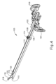
図1及び図2は、胃腸吻合手術などの様々な切断及びステープル留め手術における使用に適した例示的な線状外科用ステープラ(10)(「線状カッター」とも呼ばれる)を示す。線状外科用ステープラ(10)は、クランプされた組織の同時切断及びステープル留めのために、解放可能に一緒に連結してそれらの間に組織をクランプするように構成された、カートリッジ半体(12)(又は「再装填半体」とも呼ばれる)及びアンビル半体(14)を含む。
I. Exemplary Linear Surgical Stapler A. Overview of the Linear Surgical Stapler Figures 1 and 2 show an exemplary linear surgical stapler (10) (also referred to as a "linear cutter") suitable for use in various cutting and stapling procedures, such as gastrointestinal anastomosis procedures. The linear surgical stapler (10) includes a cartridge half (12) (also referred to as a "reloading half") and an anvil half (14) configured to releasably couple together to clamp tissue therebetween for simultaneous cutting and stapling of the clamped tissue.
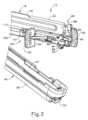
カートリッジ半体(12)は、近位フレーム部分(18)及び遠位ジョー部分(20)を有する細長いカートリッジチャネル(16)を含む。近位フレーム部分(18)は、発射アセンブリ(100)を摺動可能に保持し、横方向に対向する一対の直立側部フランジ(22)を含む。各側部フランジ(22)は、その遠位端に配置された垂直スロット(24)と、その近位端に配置されたテーパ状ノッチ(26)と、を含む。外向きに突出している補強リブ(28)は、各側部フランジ(22)の遠位スロット(24)と近位ノッチ(26)との間に長手方向に延び、剛性を高めた側部フランジ(22)を提供するように構成されている。外向きにフレア状の上部セグメント(30)は、各側フランジ(22)の近位部分の上縁部を画定し、カートリッジ半体(12)によるアンビル半体(14)の受容を容易にするように構成されている。各側部フランジ(22)は、近位ノッチ(26)と遠位スロット(24)との間で、側部フランジ(22)の下側に沿って長手方向に延在する細長い発射スロット(32)を更に含む。細長い発射スロット(32)は、発射アセンブリ(100)を近位位置と遠位位置との間で誘導するように構成されている。発射アセンブリ(100)については、図4に関連して以下により詳細に述べる。カートリッジチャネル(16)の遠位ジョー部分(20)は、ステープルカートリッジ(130)を受容(又は「再装填」)するように構成されており、これについては図6~図20に関連して下記により詳細に述べる。 The cartridge half (12) includes an elongated cartridge channel (16) having a proximal frame portion (18) and a distal jaw portion (20). The proximal frame portion (18) slidably retains the firing assembly (100) and includes a pair of laterally opposed upright side flanges (22). Each side flange (22) includes a vertical slot (24) disposed at its distal end and a tapered notch (26) disposed at its proximal end. An outwardly projecting reinforcing rib (28) extends longitudinally between the distal slot (24) and the proximal notch (26) of each side flange (22) and is configured to provide the side flanges (22) with increased stiffness. An outwardly flared upper segment (30) defines an upper edge of the proximal portion of each side flange (22) and is configured to facilitate receipt of the anvil half (14) by the cartridge half (12). Each side flange (22) further includes an elongated firing slot (32) extending longitudinally along an underside of the side flange (22) between the proximal notch (26) and the distal slot (24). The elongated firing slot (32) is configured to guide the firing assembly (100) between the proximal and distal positions. The firing assembly (100) is described in more detail below in conjunction with FIG. 4. The distal jaw portion (20) of the cartridge channel (16) is configured to receive (or "reload") a staple cartridge (130), which is described in more detail below in conjunction with FIGS. 6-20.
カートリッジ半体(12)は、カートリッジチャネル側部フランジ(22)の遠位スロット(24)とおよそ整列して配置された、クランプレバー枢動ピン(42)を用いてカートリッジチャネル(16)に枢動可能に連結されたクランプレバー(40)(「ラッチレバー」とも呼ばれる)を更に含む。クランプレバー(40)は、自由近位端(46)と、枢動ピン(42)を用いてカートリッジチャネル(16)の下部に枢動可能に連結された遠位端と、を有する細長いレバーアーム(44)を含む。一対の対向したジョー(48)は、カートリッジチャネル側部フランジ(22)と近接して、レバーアーム(44)の遠位端から遠位方向に延在する。各ジョー(48)は、以下に記載されるように、閉鎖近位端と、アンビル半体(14)のラッチピン(68)を受容するように構成された開放遠位端と、を有する湾曲スロット(50)を含む。 The cartridge half (12) further includes a clamp lever (40) (also referred to as a "latch lever") pivotally coupled to the cartridge channel (16) with a clamp lever pivot pin (42) disposed approximately in alignment with the distal slot (24) of the cartridge channel side flange (22). The clamp lever (40) includes an elongated lever arm (44) having a free proximal end (46) and a distal end pivotally coupled to a lower portion of the cartridge channel (16) with the pivot pin (42). A pair of opposed jaws (48) extend distally from the distal end of the lever arm (44) adjacent the cartridge channel side flange (22). Each jaw (48) includes a curved slot (50) having a closed proximal end and an open distal end configured to receive a latch pin (68) of the anvil half (14), as described below.
クランプレバー(40)は、レバーアーム(44)の近位端(46)がカートリッジチャネルフレーム部分(18)から離間した開放位置と、近位端(46)がカートリッジチャネルフレーム部分(18)と向かい合う閉鎖位置との間でカートリッジチャネル(16)に対して枢動するように動作可能である。図5C~図5Dに関連して以下に示され、述べられるように、クランプレバー(40)の開放位置から閉鎖位置までの作動は、クランプレバーのジョースロット(50)内でラッチピン(68)の両側の横方向端部を捕捉するように機能し、それによりアンビル半体(14)をカートリッジ半体(12)に対してクランプする。この点に関して、各ジョースロット(50)の曲率は、クランプレバー(40)が枢動可能に閉鎖されると、ラッチピン(68)のそれぞれの横方向端部に係合してこれをカートリッジチャネル(16)に向かって引くように構成されたそれぞれの上側カム表面及び下側カム表面を画定する。平坦ばね(52)の形態で示される弾性部材は、レバーアーム(44)を開放位置に向かって付勢する。したがって、平坦ばね(52)は、閉鎖位置から開放位置に向かうクランプレバー(40)の初期前進時に、クランプレバージョー(48)のアンビル半体ラッチピン(68)からの係合解除を促進する。図2及び図3に最も分かりやすく示されるように、クランプレバー(40)は、レバーアーム(44)の近位端(46)に配置されたラッチ部材(54)を更に含む。クランプレバーラッチ部材(54)は、カートリッジチャネルのフレーム部分(18)の近位端と弾性的かつ解放可能に係合し、それにより、例えばステープラ(10)が発射される間にクランプレバー(40)を閉鎖位置に解放可能に保持するように構成されている。 The clamp lever (40) is operable to pivot relative to the cartridge channel (16) between an open position in which the proximal end (46) of the lever arm (44) is spaced away from the cartridge channel frame portion (18) and a closed position in which the proximal end (46) faces the cartridge channel frame portion (18). As shown and described below in connection with Figures 5C-5D, actuation of the clamp lever (40) from the open position to the closed position functions to capture opposite lateral ends of the latch pin (68) within the jaw slots (50) of the clamp lever, thereby clamping the anvil half (14) to the cartridge half (12). In this regard, the curvature of each jaw slot (50) defines respective upper and lower camming surfaces configured to engage and pull respective lateral ends of the latch pin (68) toward the cartridge channel (16) when the clamp lever (40) is pivotally closed. A resilient member, shown in the form of a flat spring (52), biases the lever arm (44) toward the open position. The flat spring (52) thus facilitates disengagement of the clamp lever jaw (48) from the anvil half latch pin (68) upon initial advancement of the clamp lever (40) from the closed position toward the open position. As best seen in FIGS. 2 and 3, the clamp lever (40) further includes a latch member (54) disposed at the proximal end (46) of the lever arm (44). The clamp lever latch member (54) is configured to resiliently and releasably engage the proximal end of the frame portion (18) of the cartridge channel, thereby releasably retaining the clamp lever (40) in the closed position, for example, during firing of the stapler (10).
線状外科用ステープラ(10)のアンビル半体(14)は、近位フレーム部分(62)及び遠位ジョー部分(64)を有する細長いアンビルチャネル(60)を含む。近位フレーム部分(62)は、アンビル半体(14)がカートリッジ半体(12)と連結されたときにカートリッジチャネル側部フランジ(22)の間に受容されるように構成された、横方向に対向する一対の直立側部フランジ(66)を含む。ラッチピン(68)の形態の遠位ラッチ突出部は、アンビルチャネル側部フランジ(66)の遠位端を通って横方向に延在し、近位ピン(70)の形態の近位枢動突出部は、アンビルチャネル側部フランジ(66)の近位端を通って横方向に延在する。アンビルピン(68、70)は、以下に記載されるように、アンビル半体(14)とカートリッジ半体(12)との連結を容易にするように構成されている。 The anvil half (14) of the linear surgical stapler (10) includes an elongated anvil channel (60) having a proximal frame portion (62) and a distal jaw portion (64). The proximal frame portion (62) includes a pair of laterally opposed upright side flanges (66) configured to be received between the cartridge channel side flanges (22) when the anvil half (14) is coupled with the cartridge half (12). A distal latch projection in the form of a latch pin (68) extends laterally through the distal end of the anvil channel side flanges (66), and a proximal pivot projection in the form of a proximal pin (70) extends laterally through the proximal end of the anvil channel side flanges (66). The anvil pins (68, 70) are configured to facilitate coupling of the anvil half (14) with the cartridge half (12), as described below.
アンビル半体(14)の遠位ジョー部分(64)は、例えば下記により詳細に述べるように、ステープラ(10)が発射されるときにステープルカートリッジ(130)によって射出されるステープル(170)の脚部(174)を変形させるように構成された複数のステープル形成ポケット(74)(図15を参照)を有するアンビル面を画定するアンビルプレート(72)を支持する。いくつかの変形例では、アンビル面は、遠位ジョー部分(64)と一体に形成することができる。アンビル半体(14)の遠位ジョー部分(64)は、テーパ状遠位先端部材(76)を更に支持する。いくつかの変形例では、本明細書に参照によりその開示内容の全体を援用するところの2018年10月19日出願の発明の名称が「Decoupling Mechanism for Linear Surgical Stapler」である米国特許出願第16/165,587号の教示に従って、遠位先端部材(76)を遠位ジョー部分(64)に対して選択的に拡張可能とすることができる。 The distal jaw portion (64) of the anvil half (14) supports an anvil plate (72) that defines an anvil face having a plurality of staple-forming pockets (74) (see FIG. 15) configured to deform the legs (174) of the staples (170) ejected by the staple cartridge (130) when the stapler (10) is fired, e.g., as described in more detail below. In some variations, the anvil face can be formed integrally with the distal jaw portion (64). The distal jaw portion (64) of the anvil half (14) further supports a tapered distal tip member (76). In some variations, the distal tip member (76) can be selectively expandable relative to the distal jaw portion (64) in accordance with the teachings of U.S. Patent Application No. 16/165,587, filed October 19, 2018, and entitled "Decoupling Mechanism for Linear Surgical Stapler," the disclosure of which is incorporated herein by reference in its entirety.
図2に示されるように、線状外科用ステープラ(10)は、ステープラ(10)の選択部分を覆い、使用中に操作者によるステープラ(10)の効果的な把持及び操作を促進する複数のシュラウド(56、78)を更に含む。本実施例では、クランプレバーシュラウド(56)は、クランプレバーシュラウド(56)が、カートリッジチャネル(16)に対してクランプレバー(40)と共に枢動するように構成されるように、クランプレバー(40)の外向きの側面に固着され、それを覆う。更に、アンビルシュラウド(78)は、アンビルチャネル(60)の外向きの側面に固着され、それを覆う。いくつかの変形例では、本明細書に参照によりその開示内容を援用するところの2018年8月13日出願の発明の名称が「Clamping Assembly for Linear Surgical Stapler,」である米国特許出願第16/102,170号の教示に従って、アンビルシュラウド(78)をアンビルチャネル(60)と連結することができる。他の変形例では、シュラウド(56、78)は、当業者には容易に明らかな様々な他の適当な方法で、クランプレバー(40)及びアンビルチャネル(60)と連結できることが理解されよう。 As shown in FIG. 2, the linear surgical stapler (10) further includes a plurality of shrouds (56, 78) that cover select portions of the stapler (10) and facilitate effective gripping and manipulation of the stapler (10) by an operator during use. In this embodiment, the clamp lever shroud (56) is secured to and covers the outwardly facing side of the clamp lever (40) such that the clamp lever shroud (56) is configured to pivot with the clamp lever (40) relative to the cartridge channel (16). Additionally, the anvil shroud (78) is secured to and covers the outwardly facing side of the anvil channel (60). In some variations, the anvil shroud (78) can be coupled to the anvil channel (60) in accordance with the teachings of U.S. Patent Application No. 16/102,170, filed Aug. 13, 2018, and entitled "Clamping Assembly for Linear Surgical Stapler," the disclosure of which is incorporated herein by reference. In other variations, it will be understood that the shrouds (56, 78) can be coupled to the clamp lever (40) and the anvil channel (60) in a variety of other suitable ways that will be readily apparent to one of ordinary skill in the art.
図3に最も分かりやすく示されるように、カートリッジ半体(12)の近位端は、アンビル半体(14)と発射アセンブリ(100)の部分を解放可能に保持するように構成された保持アセンブリ(80)を含む。本実施例の保持アセンブリ(80)は、アンビルラッチ部材(82)及び戻り止め部材(84)を含み、これらは共に、発射スロット(32)の近位に配置された横方向に延在するピン(86)を介してカートリッジチャネル(16)の近位端と回転可能に連結される。ねじりばね(340)(図示せず)は、ピン(86)によって画定される横軸を中心として、アンビルラッチ部材(82)及び戻り止め部材を反対の回転方向に弾性的に付勢するように構成されている。 As best seen in FIG. 3, the proximal end of the cartridge half (12) includes a retention assembly (80) configured to releasably retain the anvil half (14) and a portion of the firing assembly (100). The retention assembly (80) in this example includes an anvil latch member (82) and a detent member (84), both of which are rotatably coupled to the proximal end of the cartridge channel (16) via a laterally extending pin (86) located proximal to the firing slot (32). A torsion spring (340) (not shown) is configured to resiliently bias the anvil latch member (82) and the detent member in opposite rotational directions about a transverse axis defined by the pin (86).
アンビルラッチ部材(82)は、ピン(70)がカートリッジチャネル(16)の近位テーパノッチ(26)内に案内され、それによりステープラ半体(12、14)の近位端が連結されるときに近位アンビルピン(70)を解放可能に捕捉するように構成された上部フィンガー(88)を含む。アンビルラッチ部材(82)の下端は、クランプレバー(40)がラッチフィンガー(88)から近位ピン(70)を解放するための開放位置にあり、それによりステープラ半体(12、14)の近位端を分離することができるときに、操作者によって押し込まれるように構成された解放ボタン(90)を画定する。戻り止め部材(84)は、発射アセンブリ(100)が図3に示される近位ホーム位置にあるときに発射アセンブリ(100)の摺動ブロック(102)の近位端を解放可能に捕捉するように構成された遠位フィンガー(88)を含む。戻り止め部材(84)は、摺動ブロック(102)がその近位ホーム位置の遠位方向に位置付けられている間にクランプレバーラッチ部材(54)の上端部を解放可能に捕捉するように構成された近位フック(94)を更に含み、それにより、ステープラ(10)の発射中にクランプレバーラッチ部材(54)の作動及びクランプレバー(40)が開くことを防止する。発射アセンブリ(100)がその近位ホーム位置にあるとき(すなわちステープラ(10)の発射の前又は後)、戻り止め部材(84)の近位フック(94)は、操作者による作動に応じてクランプレバーラッチ部材(54)がカートリッジチャネル(16)の近位フレーム部分(18)を回転可能に係合解放することを可能とする。その結果、次いで、クランプレバー(40)を開くことができる。カートリッジ半体(12)の保持アセンブリ(80)及び関連する構成要素については、本明細書に参照によりその開示内容を援用するところの発明の名称が「Firing System for Linear Surgical Stapler,」である2018年8月13日出願の米国特許出願第16/102,164号の教示の少なくとも一部に従って更に構成され、動作可能であってよい。 The anvil latch member (82) includes an upper finger (88) configured to releasably capture the proximal anvil pin (70) when the pin (70) is guided into the proximal tapered notch (26) of the cartridge channel (16) thereby coupling the proximal ends of the stapler halves (12, 14). The lower end of the anvil latch member (82) defines a release button (90) configured to be depressed by an operator when the clamp lever (40) is in an open position to release the proximal pin (70) from the latch finger (88) thereby allowing the proximal ends of the stapler halves (12, 14) to be separated. The detent member (84) includes a distal finger (88) configured to releasably capture the proximal end of the sliding block (102) of the firing assembly (100) when the firing assembly (100) is in the proximal home position shown in FIG. The detent member (84) further includes a proximal hook (94) configured to releasably capture an upper end of the clamp lever latch member (54) while the sliding block (102) is positioned distally of its proximal home position, thereby preventing actuation of the clamp lever latch member (54) and opening of the clamp lever (40) during firing of the stapler (10). When the firing assembly (100) is in its proximal home position (i.e., before or after firing of the stapler (10)), the proximal hook (94) of the detent member (84) enables the clamp lever latch member (54) to rotatably disengage the proximal frame portion (18) of the cartridge channel (16) in response to actuation by an operator, so that the clamp lever (40) can then be opened. The retention assembly (80) and associated components of the cartridge half (12) may be further configured and operable in accordance with at least a portion of the teachings of U.S. Patent Application No. 16/102,164, filed August 13, 2018, entitled "Firing System for Linear Surgical Stapler," the disclosure of which is incorporated herein by reference.
図4に最も分かりやすく示されるように、カートリッジ半体(12)の発射アセンブリ(100)は、摺動ブロック(102)と、摺動ブロック(102)に枢動可能に連結された一対のアクチュエータ(104、106)(又は「発射ノブ」)と、摺動ブロック(102)から遠位方向に延びる複数の細長いビーム(108、112)と、を含む。一対の側部ビーム(108)は、それらの近位端で摺動ブロック(102)の遠位端に連結され、一対のカムランプ(110)内で遠位方向に終端する。カムランプ(110)は、ステープルカートリッジ(130)内に収容されたステープルドライバ(180)の下面と係合して(図7を参照)ステープルドライバ(180)を上方に作動させることにより、ステープル(170)をカートリッジ(310)からステープルカートリッジ(310)とアンビルプレート(72)との間にクランプされた組織中に打ち込む(又は「発射する」)ように構成されている。中央ビーム(112)は、摺動ブロック(102)から遠位方向に離間したブリッジ要素(114)(又は「ナイフブロック」)を介して側部ビーム(108)と連結されている。中央ビーム(112)は、ステープラ半体(12、14)の遠位部分間にクランプされた組織を切断するように構成された遠位刃先(118)を有する遠位方向に角度付けされたナイフ部材(116)で遠位方向に終端する。中央ビーム(112)の遠位部分は、ナイフ部材(116)の近位側で上方に突出する係止要素(120)と、係止要素(120)の近位側で遠位方向に面するロックアウト突起(122)と、を更に含む。 As best seen in FIG. 4, the firing assembly (100) of the cartridge half (12) includes a slide block (102), a pair of actuators (104, 106) (or "firing knobs") pivotally coupled to the slide block (102), and a plurality of elongated beams (108, 112) extending distally from the slide block (102). The pair of side beams (108) are coupled at their proximal ends to a distal end of the slide block (102) and terminate distally in a pair of cam ramps (110). The cam ramps (110) are configured to engage the underside of the staple drivers (180) contained within the staple cartridge (130) (see FIG. 7) to actuate the staple drivers (180) upwardly, thereby driving (or "firing") the staples (170) from the cartridge (310) and into tissue clamped between the staple cartridge (310) and the anvil plate (72). The central beam (112) is connected to the side beams (108) via bridge elements (114) (or "knife blocks") that are spaced distally from the slide block (102). The central beam (112) terminates distally in a distally angled knife member (116) having a distal cutting edge (118) configured to cut tissue clamped between the distal portions of the stapler halves (12, 14). The distal portion of the central beam (112) further includes a locking element (120) that projects upwardly proximal to the knife member (116) and a lockout projection (122) that faces distally proximal to the locking element (120).
発射アセンブリ(100)の各アクチュエータ(104、106)は、例えば上記に参照によって援用する、米国特許出願公開第16/102,164号により詳細に記載されるように、一度に一方のアクチュエータ(104、106)のみが展開されるように展開位置と格納位置との間で摺動ブロック(102)に対して回転可能であるように構成されている。展開位置において、アクチュエータ(104、106)は、操作者によって遠位方向に駆動されて、発射アセンブリ(100)をステープラ(10)を通って遠位方向に作動させることにより、ステープラ半体(12、14)の間にクランプされた組織の切断及びステープル留めを同時に行うことができる。 Each actuator (104, 106) of the firing assembly (100) is configured to be rotatable relative to the sliding block (102) between a deployed position and a retracted position such that only one actuator (104, 106) is deployed at a time, as described in more detail in U.S. Patent Application Publication No. 16/102,164, incorporated by reference above. In the deployed position, the actuators (104, 106) can be driven distally by an operator to actuate the firing assembly (100) distally through the stapler (10) to simultaneously cut and staple tissue clamped between the stapler halves (12, 14).
B.線状外科用ステープラの例示的な使用
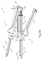
図5A~図5Eは、ステープラ半体(12、14)の例示的な連結、及び外科手術中の組み立てられたステープラ(10)のその後の発射を示す。図5Aに示されるように、カートリッジ半体(12)のクランプレバー(40)が開放位置で与えられており、ジョースロット(50)がカートリッジチャネル側部フランジ(22)の垂直スロット(24)と整列している。更に、発射アセンブリ(100)は、上記に述べた図3に示されるように、保持アセンブリ(80)の戻り止め部材(84)によってその近位ホーム位置に維持されている。この段階で、ステープル留め及び切断しようとする組織の部分(図示せず)を、カートリッジ半体(12)の遠位ジョー部分(20)内に配設されたステープルカートリッジ(130)の上に位置付けることができる。あるいは、組織は、後述するステープラ半体(12、14)の近位端を連結した後でステープルカートリッジ(130)上に位置付けることもできる。
B. Exemplary Use of a Linear Surgical Stapler Figures 5A-5E illustrate an exemplary coupling of the stapler halves (12, 14) and subsequent firing of the assembled stapler (10) during a surgical procedure. As shown in Figure 5A, the clamp lever (40) of the cartridge half (12) is provided in an open position with the jaw slot (50) aligned with the vertical slot (24) of the cartridge channel side flange (22). Additionally, the firing assembly (100) is maintained in its proximal home position by the detent member (84) of the retaining assembly (80), as shown in Figure 3, discussed above. At this stage, a portion of tissue (not shown) to be stapled and severed can be positioned on the staple cartridge (130) disposed within the distal jaw portion (20) of the cartridge half (12). Alternatively, the tissue can be positioned on the staple cartridge (130) after coupling the proximal ends of the stapler halves (12, 14), as described below.
図5A~図5Bに示されるように、ステープラ半体(12、14)の近位端部は互いに整列され、近位アンビルピン(70)がカートリッジチャネル(16)の近位テーパノッチ(26)内に下方に案内されてアンビルラッチ部材(82)の上部フィンガー(88)と係合している。この係合によってアンビルラッチ部材(82)が強制的に時計回りに弾性的に回転させられることにより、アンビルラッチ部材(82)の上部フィンガー(88)がアンビルピン(70)を捕捉し、それにより、図5Bに見られるように、ステープラ半体(12、14)の近位端が互いに解放可能に連結される。図5Cに示されるように、クランプレバー(40)が開放位置にある状態で、アンビル半体(14)が近位アンビルピン(70)を中心としてアンビル半体(14)に向かって回転させられることにより、アンビル半体(14)の遠位ラッチピン(68)がカートリッジチャネル側部フランジ(22)の垂直スロット(24)及びクランプレバー(40)のジョースロット(50)内に受容される。この時点で、ステープラ半体(12、14)の遠位ジョー部分(20、64)は、それらの間に受容された組織をクランプする前に最終的に調整することができるように、部分的に近接させられた状態にある。 As shown in Figures 5A-5B, the proximal ends of the stapler halves (12, 14) are aligned with one another and the proximal anvil pin (70) is guided downwardly into the proximal tapered notch (26) of the cartridge channel (16) to engage the upper finger (88) of the anvil latch member (82). This engagement forces the anvil latch member (82) to resiliently rotate clockwise, causing the upper finger (88) of the anvil latch member (82) to capture the anvil pin (70), thereby releasably coupling the proximal ends of the stapler halves (12, 14) to one another, as seen in Figure 5B. As shown in FIG. 5C, with the clamp lever (40) in the open position, the anvil half (14) is rotated about the proximal anvil pin (70) toward the anvil half (14) such that the distal latch pin (68) of the anvil half (14) is received within the vertical slot (24) of the cartridge channel side flange (22) and the jaw slot (50) of the clamp lever (40). At this point, the distal jaw portions (20, 64) of the stapler halves (12, 14) are in a partially approximated state to allow for final adjustment prior to clamping the tissue received therebetween.
図5Dに示されるように、クランプレバー(40)が閉鎖されてジョースロット(50)の閉鎖近位端に対してアンビルラッチピン(68)が引きつけられることにより、カートリッジ半体(12)に対してアンビル半体(14)が完全にクランプされ、組織(図示せず)がステープルカートリッジ(130)とアンビルプレート(72)との間にクランプされる。ステープルカートリッジ(130)の組織隙間ポスト(146)によってステープルカートリッジ(130)とアンビルプレート(72)との間にわずかな横方向の隙間が画定されており(図6を参照)、これにより組織はそれらの間に所定の組織圧縮度で収容される。図6に示されるように、組織隙間ポスト(146)がステープルカートリッジ(130)の遠位端に配設されており、ステープラ(10)が図5Dに示される完全にクランプされた状態にあるときにアンビルプレート(72)の遠位端に接触するように構成されている。 As shown in FIG. 5D, the clamp lever (40) is closed to draw the anvil latch pin (68) against the closed proximal end of the jaw slot (50), fully clamping the anvil half (14) against the cartridge half (12) and clamping tissue (not shown) between the staple cartridge (130) and the anvil plate (72). A slight lateral gap is defined between the staple cartridge (130) and the anvil plate (72) by the tissue gap post (146) of the staple cartridge (130) (see FIG. 6), which allows the tissue to be contained therebetween at a predetermined tissue compression. As shown in FIG. 6, the tissue gap post (146) is disposed at the distal end of the staple cartridge (130) and is configured to contact the distal end of the anvil plate (72) when the stapler (10) is in the fully clamped state shown in FIG. 5D.
図5Eに示されるように、完全にクランプされた状態に達した時点で、ステープラ(10)は、発射アセンブリ(100)の展開されたアクチュエータ(104、106)をカートリッジ半体(12)の近位フレーム部分(18)に沿って遠位方向に駆動することにより発射させることができる。図4に関連して上記に述べたように、この動作によって、発射アセンブリ(100)の細長いビーム(108、112)をステープルカートリッジ(130)内に形成された対応するチャネルを通って遠位方向に並進させ、これによりカムランプ(110)及びステープルドライバ(180)によってクランプされた組織内にステープルが発射され、同時にナイフ部材(116)がクランプされた組織を切断する。発射ストロークの完了後、発射アセンブリ(100)は、アクチュエータ(104、106)によってその近位ホーム位置に戻される。次いで、クランプレバーラッチ部材(54)を押し込むことでクランプレバー(40)の近位端をカートリッジチャネル(16)から解放し、これによりクランプレバー(40)を再び開くことが可能となる。次いで、保持アセンブリ(80)の解放ボタン(90)を押し込むことでアンビル半体(14)をカートリッジ半体(12)から解放することができ、そのため、ステープラ半体(12、14)を互いから分離し、それにより新たにステープル留めされ、切断された組織を解放することができる。いくつかの変形例では、ステープラ(10)は、参照によって本明細書に援用するところの米国特許出願公開第16/165,587号に開示される機構と同様のステープラ半体(12、14)の分離を促進する機構を含むことができる点は理解されよう。 Once the fully clamped condition is reached, as shown in FIG. 5E, the stapler (10) can be fired by driving the deployed actuators (104, 106) of the firing assembly (100) distally along the proximal frame portion (18) of the cartridge half (12). As described above in connection with FIG. 4, this action translates the elongated beams (108, 112) of the firing assembly (100) distally through corresponding channels formed in the staple cartridge (130), thereby firing staples into the clamped tissue by the cam ramps (110) and staple driver (180) while the knife member (116) cuts the clamped tissue. After completion of the firing stroke, the firing assembly (100) is returned to its proximal home position by the actuators (104, 106). The clamp lever latch member (54) is then depressed to release the proximal end of the clamp lever (40) from the cartridge channel (16), thereby allowing the clamp lever (40) to reopen. The release button (90) of the retaining assembly (80) can then be depressed to release the anvil half (14) from the cartridge half (12), thereby separating the stapler halves (12, 14) from one another, thereby releasing the newly stapled and severed tissue. It will be appreciated that in some variations, the stapler (10) can include a mechanism to facilitate separation of the stapler halves (12, 14) similar to the mechanism disclosed in U.S. Patent Application Publication No. 16/165,587, which is incorporated herein by reference.
II.3次元ステープルの適切な成型を促すステープルドライバ及び組織把持機構を有する例示的なステープルカートリッジ
図15~図16に関連して以下に述べるように、線状外科用ステープラ(10)のステープルカートリッジ(130)は、脚先端部が互いから横方向にオフセットされるように各ステープル(170)の脚部が形成されることで非平面形状の形成後ステープル(170)を与える、3次元(「3D」)の形成構成を有するステープル(170)を適用するように構成されている。かかるステープルの構成は、患者組織に適用された得られたステープルラインに沿った高い止血性及び更には圧縮力の均一な分布を与える点で有利である。加えて、ステープルカートリッジ(130)にはスタンドオフ部材(152、160、162、164)が設けられていることにより、上記に述べたステープル留め及び切断工程の間に、ステープルカートリッジ(130)がステープルカートリッジ(130)とアンビルプレート(72)との間にクランプされた組織を効果的に把持する能力が高められる。したがって、ステープル(170)の適切な3D形成を促す適当なクリアランスを与え、ステープルの形成不良を防止するために、ステープルカートリッジ(130)の特定の機構を適当な形状にすることが望ましい場合がある。かかるクリアランスが設けられることは、ステープルカートリッジ(130)を発射するために発射アセンブリ(100)を遠位方向に作動させるのに必要なユーザによる入力の力を低減させる点でも有利である。
II. Exemplary Staple Cartridge with Staple Driver and Tissue Gripping Features to Promote Proper Formation of Three-Dimensional Staples As described below in conjunction with Figures 15-16, the staple cartridge (130) of the linear surgical stapler (10) is configured to apply staples (170) having a three-dimensional ("3D") formed configuration in which the legs of each staple (170) are formed such that the leg tips are laterally offset from one another to provide a non-planar shaped formed staple (170). Such a staple configuration is advantageous in providing enhanced hemostasis as well as a uniform distribution of compressive force along the resulting staple line applied to the patient's tissue. Additionally, the staple cartridge (130) is provided with standoff members (152, 160, 162, 164) that enhance the ability of the staple cartridge (130) to effectively grasp tissue clamped between the staple cartridge (130) and the anvil plate (72) during the stapling and severing process described above. Accordingly, it may be desirable to appropriately shape certain features of staple cartridge (130) to provide appropriate clearance to promote proper 3D formation of staples (170) and prevent poor staple formation. Providing such clearance may also be advantageous in reducing the user input force required to distally actuate firing assembly (100) to fire staple cartridge (130).
以下に示され、述べられる機構は、線状外科用ステープラ(10)のステープルカートリッジ(130)との関連で示されるが、かかる機構は様々な他のタイプの外科用ステープラと共に使用するように構成されたステープルカートリッジにも適用できる点は理解されよう。 Although the mechanisms shown and described below are illustrated in the context of a staple cartridge (130) of a linear surgical stapler (10), it will be understood that such mechanisms are also applicable to staple cartridges configured for use with various other types of surgical staplers.
A.例示的なステープルカートリッジの概要
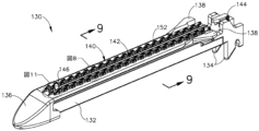
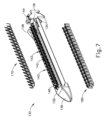
図6及び図7に示されるように、ステープルカートリッジ(130)は、細長いカートリッジ本体(132)、並びにカートリッジ本体(132)内に収容された複数のステープル(170)及びステープルドライバ(180)を含む。スイングタブ(144)の形態のロックアウトバイパス機構が、カートリッジ本体(132)の近位端に回転可能に連結されており、以下でより詳細に述べる。いくつかの変形例では、ステープルカートリッジ(130)は、カートリッジ本体(132)の下側に沿って延在し、カートリッジ本体(132)内のステープル(170)及びステープルドライバ(180)の保持を助ける底部トレイ(図示せず)を更に含むことができる。
A. Overview of an Exemplary Staple Cartridge As shown in Figures 6 and 7, the staple cartridge (130) includes an elongated cartridge body (132) and a plurality of staples (170) and staple drivers (180) housed within the cartridge body (132). A lockout bypass mechanism in the form of a swing tab (144) is rotatably coupled to a proximal end of the cartridge body (132) and will be described in more detail below. In some variations, the staple cartridge (130) can further include a bottom tray (not shown) that extends along the underside of the cartridge body (132) and aids in retaining the staples (170) and staple drivers (180) within the cartridge body (132).
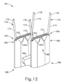
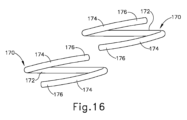
図12を簡単に参照すると、各ステープル(170)は、中央クラウン(172)と、クラウン(172)から離れる方向に延び、脚先端部(176)を有する一対の脚部(174)とを有している。ステープル(170)の未形成状態では、クラウン(172)と脚部(174)とがU字形状を形成し、この形状では脚先端部(176)がクラウン(172)から離れる方向に延び、クラウン(172)と脚部(174)とが共通の平面内にあるために未形成ステープル(170)は2次元形状を有している。図15及び図16を簡単に参照すると、ステープル(170)の3D形成後の状態では、各脚部(174)は、アンビルプレート(72)の対応するステープル形成ポケット(74)によって、各脚先端部(176)がクラウン(172)に向かって延びるように曲げられている。より具体的には、図16に示されるように、各形成された脚先端部(176)は、互いから、かつクラウン(172)の両側でクラウン(172)から横方向にオフセットされており、これにより上記に述べたような機能的利点を備えた3次元形状を有する形成後ステープル(170)を与える。 With brief reference to FIG. 12, each staple (170) has a central crown (172) and a pair of legs (174) extending away from the crown (172) and having leg tips (176). In the unformed state of the staple (170), the crown (172) and legs (174) form a U-shape in which the leg tips (176) extend away from the crown (172), and the unformed staple (170) has a two-dimensional shape because the crown (172) and legs (174) lie in a common plane. With brief reference to FIGS. 15 and 16, in the 3D formed state of the staple (170), each leg (174) is bent by a corresponding staple forming pocket (74) in the anvil plate (72) such that each leg tip (176) extends toward the crown (172). More specifically, as shown in FIG. 16, each formed leg tip (176) is laterally offset from one another and from the crown (172) on either side of the crown (172), thereby providing the formed staple (170) with a three-dimensional shape with the functional advantages discussed above.
図6及び図7に戻ると、本実施例のカートリッジ本体(132)は、長手方向軸に沿って、一対のフック(134)を有する近位端とテーパ状ノーズ(136)を有する遠位端との間で直線状に延びている。近位フック(134)は、ステープルカートリッジ(130)がカートリッジチャネル(16)の遠位ジョー部分(20)内に着座されるときにクランプレバーの枢動ピン(42)を解放可能に捕捉し、カートリッジチャネル(16)の床に形成された対応する開口部を通って下方に延びるように構成されている。カートリッジ本体(132)の側面の近位端の近くに配設された一対の翼状タブ(138)は、遠位ジョー部分(20)に対するステープルカートリッジ(130)の挿入及び取り出しを容易にするように構成されている。 6 and 7, the cartridge body (132) of this embodiment extends linearly along the longitudinal axis between a proximal end having a pair of hooks (134) and a distal end having a tapered nose (136). The proximal hooks (134) are configured to releasably capture the pivot pin (42) of the clamp lever when the staple cartridge (130) is seated in the distal jaw portion (20) of the cartridge channel (16) and extend downwardly through a corresponding opening formed in the floor of the cartridge channel (16). A pair of wing-like tabs (138) disposed near the proximal end on the sides of the cartridge body (132) are configured to facilitate insertion and removal of the staple cartridge (130) from the distal jaw portion (20).
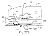
図6~図9に最も分かりやすく示されるように、カートリッジ本体(132)の上面はデッキ(140)を画定している。細長いナイフスロット(142)が、デッキ(140)を通ってステープルカートリッジ(130)の長手方向軸に沿って長手方向に延び、上記に述べたような発射アセンブリ(100)のナイフ部材(116)の遠位作動に応じて、そのナイフ部材をナイフスロットを通じて摺動可能に受容するように構成されている。スイングタブ(144)の形態の発射ロックアウトバイパス機構が、ナイフスロット(142)の近位端においてカートリッジ本体(132)に回転可能に連結されている。スイングタブ(144)は、スイングタブ(144)がナイフスロット(142)の近位端を垂直に横切って延びる展開位置と、スイングタブ(144)がナイフスロット(142)と平行に延びる格納位置との間で回転するように構成されている。図27A~図27Bに関連して以下に示され、述べられるように、スイングタブ(144)は展開位置では、発射アセンブリ(100)をロックアウト状態から、発射ビーム(108、112)がステープルカートリッジ(130)を通って遠位方向に並進して、ステープラ(10)によってクランプされた組織のステープル留め及び切断を行うことができる発射状態へと付勢するように構成されている。 As best seen in FIGS. 6-9, the upper surface of the cartridge body (132) defines a deck (140). An elongated knife slot (142) extends longitudinally through the deck (140) along the longitudinal axis of the staple cartridge (130) and is configured to slidably receive the knife member (116) of the firing assembly (100) therethrough in response to distal actuation of the knife member as described above. A firing lockout bypass mechanism in the form of a swing tab (144) is rotatably coupled to the cartridge body (132) at the proximal end of the knife slot (142). The swing tab (144) is configured to rotate between a deployed position in which the swing tab (144) extends perpendicularly across the proximal end of the knife slot (142) and a retracted position in which the swing tab (144) extends parallel to the knife slot (142). As shown and described below in connection with FIGS. 27A-27B, in the deployed position, the swing tab (144) is configured to bias the firing assembly (100) from a locked out state to a fired state in which the firing beams (108, 112) can translate distally through the staple cartridge (130) to staple and sever tissue clamped by the stapler (10).
剛性の組織隙間ポスト(146)がナイフスロット(142)の遠位端に固定され、カートリッジデッキ(140)から離れる方向に上方に突出している。組織隙間ポスト(146)の丸みを帯びた上端部は、アンビルプレート(72)の遠位端に接触するように構成されており、それにより、ステープラ半体(12、14)が上記に述べたような形で互いにクランプされるときにカートリッジデッキ(140)とアンビルプレート(72)と間に組織隙間を画定する。 A rigid tissue gap post (146) is secured to the distal end of the knife slot (142) and projects upwardly away from the cartridge deck (140). The rounded upper end of the tissue gap post (146) is configured to contact the distal end of the anvil plate (72), thereby defining a tissue gap between the cartridge deck (140) and the anvil plate (72) when the stapler halves (12, 14) are clamped together as described above.
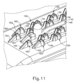
一対の細長いリブ(148)がナイフスロット(142)及び細長いリブ(148)の両側に沿って延在しており、デッキ(140)から離れる方向に突出してせり上がった表面を画定している。細長いリブ(148)はナイフスロット(142)の近位端と遠位端で終端し、ナイフスロット(142)に沿った組織の高い把持性を促進するように構成されており、これによりナイフ部材(116)による切断中の組織を安定化させる。図11に示されるように、本変形例の細長いリブ(148)は、組織隙間ポスト(146)の近位に配設されたテーパした遠位端を有している。 A pair of elongated ribs (148) extend along either side of the knife slot (142) and define raised surfaces projecting away from the deck (140). The elongated ribs (148) terminate at the proximal and distal ends of the knife slot (142) and are configured to promote a high grip of tissue along the knife slot (142), thereby stabilizing the tissue during cutting by the knife member (116). As shown in FIG. 11, the elongated ribs (148) of this variation have tapered distal ends disposed proximal to the tissue clearance post (146).
ステープルカートリッジ(130)のカートリッジ本体(132)は、カートリッジ本体(132)を通って横断方向に延在し、デッキ(140)に開口する複数のステープル開口部(150)を更に含む。本実施例では、ステープル開口部(150)は、ナイフスロット(142)の両側に沿って第1及び第2の平行な列に配置されており、各列のステープル開口部(150)は、隣接する列のステープル開口部(150)に対して長手方向に互い違いとなっている。ステープル開口部(150)の様々な適当な配置及び量が、ステープルカートリッジ(130)の他の変形例で提供され得る点は理解されよう。各ステープルキャビティ(150)は、それぞれのステープルドライバ(180)及びステープル(170)を内部に収容するように構成されている。上記に述べたように、発射アセンブリの各カムランプ(110)は、ステープルドライバ(180)の下面に係合し、ステープル開口部(150)内でステープルドライバ(180)を上方に作動させることによってステープル開口部(150)から組織内へ、更にアンビルプレート(72)に対してステープル(170)を打ち込む(すなわち「発射する」)ように構成されている。 The cartridge body (132) of the staple cartridge (130) further includes a plurality of staple openings (150) extending transversely through the cartridge body (132) and opening into the deck (140). In this embodiment, the staple openings (150) are arranged in first and second parallel rows along either side of the knife slot (142), with the staple openings (150) in each row being longitudinally staggered relative to the staple openings (150) in adjacent rows. It will be appreciated that various suitable arrangements and quantities of staple openings (150) may be provided in other variations of the staple cartridge (130). Each staple cavity (150) is configured to receive a respective staple driver (180) and staple (170) therein. As discussed above, each cam ramp (110) of the firing assembly is configured to engage the underside of a staple driver (180) and actuate the staple driver (180) upwardly within the staple opening (150) to drive (i.e., "fire") the staple (170) from the staple opening (150) into tissue and against the anvil plate (72).
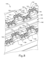
図8~図11に最も分かりやすく示されるように、ステープルカートリッジ(130)は、カートリッジデッキ(140)上に配置され、カートリッジデッキから上方に突出するスタンドオフ部材(152、160、162、164)の形態の複数の組織把持部材を更に含む。スタンドオフ部材(152、160、162、164)はデッキ(140)の長さに沿って分布されており、ナイフスロット(142)及び細長いリブ(148)から横方向にオフセットされて、それぞれの1つ以上のステープル開口部(150)と整列してそのステープル開口部に開口している。下記に述べるように、スタンドオフ部材(152、160、162、164)は、デッキ(140)とアンビルプレート(72)とが互いにクランプされるときに組織を把持することによって組織を安定化させ、更には、ステープル位置における組織の圧縮を最適化して組織の効果的なステープル留め及び切断を促すように構成されている。本変形例ではスタンドオフ部材(152、160、162、164)はカートリッジ本体(132)と一体に形成されているが、他の変形例では、スタンドオフ部材(152、160、162、164)をカートリッジ本体(132)とは別体として形成して、カートリッジ本体と連結してもよい点は理解されよう。 As best seen in FIGS. 8-11, the staple cartridge (130) further includes a plurality of tissue gripping members in the form of standoff members (152, 160, 162, 164) disposed on and projecting upwardly from the cartridge deck (140). The standoff members (152, 160, 162, 164) are distributed along the length of the deck (140) and are laterally offset from the knife slot (142) and the elongated rib (148) to align with and open to a respective one or more staple openings (150). As described below, the standoff members (152, 160, 162, 164) are configured to grip the tissue when the deck (140) and the anvil plate (72) are clamped together, thereby stabilizing the tissue, and further to optimize compression of the tissue at the staple location to facilitate effective stapling and severing of the tissue. In this variation, the standoff members (152, 160, 162, 164) are formed integrally with the cartridge body (132), but it will be understood that in other variations, the standoff members (152, 160, 162, 164) may be formed separately from the cartridge body (132) and connected to the cartridge body.
図8~図10に示されるように、ステープルデッキ(140)上の第1の群のスタンドオフ部材は、ナイフスロット(142)の長さに沿ってステープル開口部(150)と位置を合わせて個別に配置されたクリート(152)の形態として示されている。各クリート(152)は、長手方向の反対側に面する一対の端部機構(154)を含む。詳細には、第1の端部機構(154)は、ステープル開口部(150)の所与の列内の第1のステープル開口部(150)の端部分に開口してその周囲を部分的に包囲し、反対側の第2の端部機構(154)は、ステープル開口部(150)の同じ列内の隣接する第2のステープル開口部(150)の端部分に開口してその周囲を部分的に包囲している。第1及び第2の端部機構(154)は凹状ブリッジ機構(156)によって一体に接続されている。 8-10, the first group of standoff members on the staple deck (140) are shown in the form of cleats (152) that are individually positioned in alignment with the staple openings (150) along the length of the knife slot (142). Each cleat (152) includes a pair of longitudinally opposing end features (154). In particular, a first end feature (154) opens into and partially surrounds an end portion of a first staple opening (150) in a given row of staple openings (150), and an opposing second end feature (154) opens into and partially surrounds an end portion of an adjacent second staple opening (150) in the same row of staple openings (150). The first and second end features (154) are connected together by a concave bridge feature (156).
クリート(152)の各端部機構(154)は、クリート(152)の高さに沿って、デッキ(140)に平行に延びる平面内でほぼU字状の断面を有している。各端部機構(154)はまた、それぞれのステープル開口部(150)の内壁につながり、そこから外側に突出する内壁を画定している。このようにして、各端部機構(154)は、それぞれのステープル開口部(150)に開口して、そのステープル開口部と連通している。したがって、各端部機構(154)は、ステープルドライバ(180)によってステープル(170)がステープル開口部(150)から上方に射出されるときに、対応するステープル(170)(図12を参照)のそれぞれのステープル脚部(174)、及びそれぞれのステープルドライバ(180)を案内するように構成されている。したがって、各端部形成部(154)は、隣接するクリート(152)の対面する端部機構(154)と、又は下記に述べるエンドキャップ(160)(図11を参照)と協働して、このようなステープル(170)及びステープルドライバ(180)の案内を与える。 Each end feature (154) of the cleat (152) has a generally U-shaped cross-section in a plane extending parallel to the deck (140) along the height of the cleat (152). Each end feature (154) also defines an inner wall that connects to and projects outwardly from the inner wall of the respective staple opening (150). In this manner, each end feature (154) opens into and communicates with the respective staple opening (150). Each end feature (154) is thus configured to guide the respective staple legs (174) of the corresponding staple (170) (see FIG. 12) and the respective staple driver (180) as the staple (170) is ejected upwardly from the staple opening (150) by the staple driver (180). Thus, each end formation (154) cooperates with the facing end feature (154) of the adjacent cleat (152) or with an end cap (160) (see FIG. 11) described below to provide guidance for such staples (170) and staple drivers (180).
図8及び図10に最も分かりやすく示されるように、クリート(152)の各端部機構(154)は、クリート(152)の高さに沿ってそれぞれの凹状ブリッジ機構(156)に向かってデッキ(140)から離れる方向にテーパしているため、各クリート(152)に台形の側断面が与えられる。これに関して、図10に最も分かりやすく示されるように、各端部機構(154)は、凹状ブリッジ機構(156)に向かって傾斜しており、その高さに沿って丸みを帯びた、角度付き端面(155)を含む。角度付き端面(155)のこの丸みを帯びた構成によって、各端部機構(154)がそれぞれのステープル脚部(174)及びそれぞれのステープルドライバ(180)と対面し、それによりステープル(170)及びステープルドライバ(180)を効果的に上方に案内することができる一方で、ステープル脚部(174)の適正な3D形成を促すための効果的なクリアランスが与えられる。特に、角度付き端面(155)の丸みを帯びた構成は、ステープル脚部(174)の形成不良を誘発させる可能性がある、ステープル脚部(174)がアンビルプレート(72)によって形成されるときにステープル脚部(174)の先端部が端部機構(154)と衝突するリスクを低減する。 As best seen in Figures 8 and 10, each end feature (154) of the cleat (152) tapers away from the deck (140) toward a respective concave bridge feature (156) along the height of the cleat (152), thereby providing each cleat (152) with a trapezoidal side cross-section. In this regard, as best seen in Figure 10, each end feature (154) includes an angled end surface (155) that slopes toward the concave bridge feature (156) and is rounded along its height. This rounded configuration of the angled end surface (155) allows each end feature (154) to face a respective staple leg (174) and respective staple driver (180), thereby effectively guiding the staples (170) and staple drivers (180) upward, while providing effective clearance to facilitate proper 3D formation of the staple legs (174). In particular, the rounded configuration of the angled end surface (155) reduces the risk of the tip of the staple leg (174) colliding with the end feature (154) as the staple leg (174) is formed by the anvil plate (72), which can lead to poor formation of the staple leg (174).
図8及び図10に示されるように、本実施例のカートリッジデッキ(140)上のクリート(152)の横方向に最も外側の列には、ステープルカートリッジ(130)の長さに対して角度が付けられた平坦面(158)を有する外側側面が形成されている。したがって、これらの特定のクリート(152)はそれらの長手方向軸を中心として非対称であり、これは、カートリッジ本体(132)を形成するための型成形プロセスを容易とする助けとなり得る。 As shown in FIGS. 8 and 10, the laterally outermost rows of cleats (152) on the cartridge deck (140) of this embodiment are formed with outer sides having flat surfaces (158) that are angled relative to the length of the staple cartridge (130). Thus, these particular cleats (152) are asymmetric about their longitudinal axis, which may help facilitate the molding process for forming the cartridge body (132).
本実施例のクリート(152)は、各クリート(152)が独立し、隣接するクリート(152)から離間するように、互いに対して個別に形成されているが、他の変形例では、クリート(152)は、カートリッジデッキ(140)の1つ以上の部分に沿って互いに相互接続されてもよい。 The cleats (152) in this embodiment are formed individually relative to one another such that each cleat (152) is independent and spaced apart from adjacent cleats (152), but in other variations, the cleats (152) may be interconnected to one another along one or more portions of the cartridge deck (140).
図11に示されるように、カートリッジデッキ(140)は、ステープル開口部(150)の列の遠位端に配設された、近位側に面したエンドキャップ(160)の形態の更なるスタンドオフ部材を含む。本変形例では、各エンドキャップ(160)の近位部分は、上記に述べたクリートの端部機構(154)と同様の形状となっている。詳細には、各エンドキャップ(160)の近位部分はU字形状を有しており、それぞれのステープル開口部(150)の遠位端部分の周囲を部分的に包囲している。したがって、各エンドキャップ(160)は、ステープルカートリッジ(130)の発射の間に、同じ列内の隣接するクリート(152)の対面する端部機構(154)と協働して、それぞれのステープル(170)及びステープルドライバ(180)を案内する。本実施例では、各エンドキャップ(160)は、カートリッジノーズ(136)に向かって遠位方向にテーパした遠位ランプ機構(162)を更に含む。同様のランプ機構(164)が、組織隙間ポスト(146)の遠位側に組織隙間ポストと長手方向に整列して位置付けられている。ランプ機構(162、164)は、組織がクリート(152)、エンドキャップ(160)、又は組織隙間ポスト(146)にひっかかったり、又は他の形で付着したりすることなく、組織構造内又はその下側へのステープラ(10)のカートリッジ半体(12)の遠位端の滑らかな挿入を促すように構成されている。 As shown in FIG. 11, the cartridge deck (140) includes additional standoff members in the form of proximally facing end caps (160) disposed at the distal ends of the rows of staple openings (150). In this variation, the proximal portion of each end cap (160) is shaped similarly to the cleat end features (154) described above. In particular, the proximal portion of each end cap (160) has a U-shape and partially wraps around the distal end portion of the respective staple openings (150). Thus, each end cap (160) cooperates with the facing end features (154) of the adjacent cleats (152) in the same row to guide the respective staples (170) and staple drivers (180) during firing of the staple cartridge (130). In this embodiment, each end cap (160) further includes a distal ramp feature (162) tapering distally toward the cartridge nose (136). A similar ramp mechanism (164) is positioned distal to and in longitudinal alignment with the tissue gap post (146). The ramp mechanisms (162, 164) are configured to facilitate smooth insertion of the distal end of the cartridge half (12) of the stapler (10) into or beneath the tissue structure without tissue catching or otherwise adhering to the cleat (152), end cap (160), or tissue gap post (146).
本実施例では、スタンドオフ部材(152、160、162、164)は、均一な最大高さでカートリッジデッキ(140)から突出し、したがってせり上がった組織係合面を集合的に画定している。他の変形例では、スタンドオフ部材(152、160、162、164)は、異なる高さでカートリッジデッキ(140)から突出し、したがって2つ以上のせり上がった組織係合面を画定してもよい。 In this embodiment, the standoff members (152, 160, 162, 164) protrude from the cartridge deck (140) at a uniform maximum height, thus collectively defining a raised tissue-engaging surface. In other variations, the standoff members (152, 160, 162, 164) may protrude from the cartridge deck (140) at different heights, thus defining two or more raised tissue-engaging surfaces.
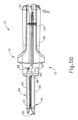
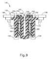
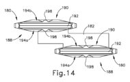
図12~図14は、ステープルカートリッジ(130)の例示的なステープルドライバ(180)の対を示す。本実施例では、ステープルドライバ(180)の各対は、ステープルドライバ(180)をそれらの下端(186)で相互接続するブリッジ要素(182)を有するドライバユニット(181)として一体に形成されている。ドライバユニット(181)のステープルドライバ(180)は、ステープルカートリッジ(130)の長手方向軸に対して互いから横方向かつ長手方向にオフセットされた互い違いの形で配置されており、そのため、ステープルドライバ(180)はカートリッジ本体(132)の対応するステープル開口部(150)と整列するように構成されている。図12に示されるように、各ステープルドライバ(180)は、上端(184)、下端(186)、第1の側面(188)、及び反対側の第2の側面(190)を含む。図14に見られるように、本実施例のステープルドライバ(180)は、その高さに沿って形成されており、第1の側面及び第2の側面(188,190)を画定する細長い八角形の形状を有する横断面を有している。ステープルドライバ(180)の上端(184)は、対応するステープル(170)のクラウン(172)を受容して支持するように構成された溝(192)を含む。 12-14 show an exemplary pair of staple drivers (180) of the staple cartridge (130). In this embodiment, each pair of staple drivers (180) is integrally formed as a driver unit (181) having bridge elements (182) that interconnect the staple drivers (180) at their lower ends (186). The staple drivers (180) of the driver unit (181) are arranged in a staggered manner that is laterally and longitudinally offset from one another relative to the longitudinal axis of the staple cartridge (130) such that the staple drivers (180) are configured to align with corresponding staple openings (150) in the cartridge body (132). As shown in FIG. 12, each staple driver (180) includes an upper end (184), a lower end (186), a first side (188), and an opposite second side (190). As seen in FIG. 14, the staple driver (180) of this embodiment has a cross-section formed along its height with an elongated octagonal shape that defines first and second sides (188, 190). The upper end (184) of the staple driver (180) includes a groove (192) configured to receive and support the crown (172) of a corresponding staple (170).
本実施例の各ステープルドライバ(180)には、上端(184)に開口し、かつステープラ(10)が発射されるときのアンビルプレート(72)によるステープル脚部(174)の形成時にステープルの脚先端部(176)を受容するように構成されたポケット(194a、194b)が形成されている。詳細には、ドライバ(180)の第1の側面(188)は、第1の隣接するポケットの対(194a)を上端(184)に含み、第2の側面(190)は、第2の隣接するポケットの対(194b)を上端(184)に含む。本変形例では、ポケット(194a、194b)は均一な形状を有しており、第1の側面(188)の各ポケット(194a)と第2の側面(190)の反対側のポケット(194b)とが整列するように対称的に配置されている。 Each staple driver (180) in this embodiment is formed with pockets (194a, 194b) opening at the top end (184) and configured to receive the staple leg tips (176) when the staple legs (174) are formed by the anvil plate (72) when the stapler (10) is fired. In particular, the first side (188) of the driver (180) includes a first pair of adjacent pockets (194a) at the top end (184) and the second side (190) includes a second pair of adjacent pockets (194b) at the top end (184). In this variation, the pockets (194a, 194b) have a uniform shape and are symmetrically arranged such that each pocket (194a) on the first side (188) is aligned with the opposite pocket (194b) on the second side (190).
ステープルドライバ(180)の各ポケット(194a、194b)は、上端(184)のそれぞれの面取り面(196)によって画定され、それぞれの側面(188、190)の中央に位置付けられたボス(198)によって同じ側面(188、190)の隣接するポケット(194a、194b)から分離されている。各面取り面(196)は溝(192)に向かって角度付けされているため、第1の側面(188)のポケット(194a、194b)と第2の側面(190)のポケット(194a、194b)とはそれらの上端において互いに向かって角度付けされている。各ポケット(194a、194b)は下端(186)に向かう方向に幅がテーパしているため、ほぼ台形の形状を有している。これに対して、各ボス(198)は上端(184)に向かう方向に幅がテーパしており、ほぼ三角形の形状を有している。更に、各ボス(198)が上部溝(192)の中央付近で各対応するポケット(194a、194b)の内側側壁を画定しているのに対して、各ポケット(194a、194b)は上部溝(192)の対応する端部付近で反対側の側面に開口している。ボス(198)は、ステープルカートリッジ(130)の組み立て時の上部溝(192)内のステープルクラウン(172)の適正な着座を助けるように構成されている。 Each pocket (194a, 194b) of the staple driver (180) is defined by a respective chamfered surface (196) on the top end (184) and is separated from an adjacent pocket (194a, 194b) on the same side (188, 190) by a boss (198) centrally located on each side (188, 190). Each chamfered surface (196) is angled toward the groove (192) such that the pockets (194a, 194b) on the first side (188) and the pockets (194a, 194b) on the second side (190) are angled toward each other at their top ends. Each pocket (194a, 194b) tapers in width toward the bottom end (186) and thus has a generally trapezoidal shape. In contrast, each boss (198) tapers in width toward the top end (184) and thus has a generally triangular shape. Additionally, each boss (198) defines an inner sidewall of each corresponding pocket (194a, 194b) near the center of the upper groove (192), while each pocket (194a, 194b) opens to an opposite side near the corresponding end of the upper groove (192). The bosses (198) are configured to aid in proper seating of the staple crown (172) within the upper groove (192) during assembly of the staple cartridge (130).
図15に示されるように、ステープルドライバ(180)の各ポケット(194a、194b)は、ステープル(170)の形成時にステープル脚先端部(176)を受容するように構成されており、そのため、各ステープル脚先端部(176)はステープルドライバ(180)のそれぞれの面取り面(196)と対面する(必ずしも接触はしない)。その結果、また、有利な点として、ステープルドライバ(180)にポケット(194a、194b)が設けられていることは、上記に述べたクリート(152)の丸みを帯びた角度付き端面(155)と併せて、ステープル(170)の形成不良を誘発するような形でステープル脚部(174)がステープルドライバ(180)の側面又はクリート(152)の端部機構(154)に衝突することなく、ステープル(170)の適正な3D形成を可能とする。 As shown in FIG. 15, each pocket (194a, 194b) of the staple driver (180) is configured to receive a staple leg tip (176) during formation of the staple (170) such that each staple leg tip (176) faces (but does not necessarily contact) a respective chamfered surface (196) of the staple driver (180). As a result, and advantageously, the provision of the pockets (194a, 194b) on the staple driver (180), in combination with the rounded and angled end surfaces (155) of the cleat (152) discussed above, allows for proper 3D formation of the staple (170) without the staple legs (174) striking the sides of the staple driver (180) or the end features (154) of the cleat (152) in a manner that would cause the staple (170) to be poorly formed.
図15に示されるように、ステープル(170)の第1の脚先端部(176)は、3Dステープル形成時にドライバ(180)の第1の側面(188)のポケット(194a)内に受容される。同様に、第2の脚先端部(176)は、第1のポケット(194a)から対角線上で反対にある第2の側面(190)のポケット(194b)内に受容される。したがって、第1の側面(188)の残りのポケット(194a)と対角線上で反対にある第2の側面(190)の残りのポケット(194b)は、本実施例では使用されないままである。しかしながら、ステープルドライバ(180)の各側面(188、190)に一対のポケット(194a、194b)が設けられていることにより、ステープルドライバ(180)は、アンビルプレート(72)のステープル形成ポケット(74)の別の構成及びその結果として得られるステープル(170)の3D形成された構成に適合できる点は理解されよう。例えば、いくつかの変形例では、上記に代えて、アンビルプレート(72)のステープル形成ポケット(74)の少なくとも一部のものを、図15に示される、対角線上で反対にあるポケット(194a、194b)の未使用の対にステープル脚部(174)を方向付けるように構成することもできる。したがって、各ステープルドライバ(180)は、図16に示される3D構成に対して鏡像関係にある3D構成を有するステープル(170)の形成に適合するように構成されている。 As shown in FIG. 15, the first leg tip (176) of the staple (170) is received within a pocket (194a) on a first side (188) of the driver (180) during 3D staple formation. Similarly, the second leg tip (176) is received within a pocket (194b) on a second side (190) diagonally opposite from the first pocket (194a). Thus, the remaining pocket (194a) on the first side (188) and the remaining pocket (194b) on the second side (190) diagonally opposite are left unused in this embodiment. However, it will be appreciated that the provision of a pair of pockets (194a, 194b) on each side (188, 190) of the staple driver (180) allows the staple driver (180) to accommodate alternative configurations of the staple forming pockets (74) of the anvil plate (72) and the resulting 3D formed configurations of the staples (170). For example, in some variations, at least some of the staple forming pockets (74) of the anvil plate (72) can alternatively be configured to direct the staple legs (174) into an unused pair of diagonally opposed pockets (194a, 194b) shown in FIG. 15. Thus, each staple driver (180) is configured to accommodate the formation of staples (170) having a 3D configuration that is a mirror image of the 3D configuration shown in FIG. 16.
B.ステープルカートリッジの例示的な代替的ステープルドライバ
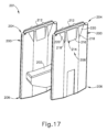
用途によっては、上記の代わりに、ステープルカートリッジ(130)を、異なる厚さの患者組織への発射に適合するように構成することが望ましい場合がある。例えば、上記の代わりに、カートリッジデッキ(140)及びスタンドオフ部材(152、160、162、164)の寸法を、例えば、血管構造の組織などの比較的薄い組織のステープル留めに適合するように構成することができる。そのようなステープルカートリッジ(130)の代替的な変形例では、ステープル(170)は図16に示されるステープル形状に対して若干異なる3D形成された形状をとることができる。例えば、ステープル脚部(174)を、形成後ステープル(170)がより小さな形成後高さ(例えば、およそ0.035インチ~0.040インチ)を有し、図20に示されるように、脚先端部(176)がクラウン(172)の両端よりもクラウン(172)の中心の近くに位置付けられるように形成することができる。その結果、ステープルドライバ(180)のポケット(194a、194b)及びボス(198)は、ステープルの形成不良及びその結果生じる外科用ステープラ(10)を発射するために必要とされるユーザ入力の力の増大につながり得る、ステープルドライバ(180)の機構に対するステープル脚部(174)の望ましくない衝突を生じることなく、そのようなステープル(170)の3D形成の違いに適合するような若干の再構成を許容し得る。ステープルドライバ(180)のそのような例示的な変形形態について、以下により詳細に述べる。
B. Exemplary Alternative Staple Drivers for a Staple Cartridge In some applications, it may be desirable to alternatively configure the staple cartridge (130) to accommodate firing into patient tissue of different thicknesses. For example, the dimensions of the cartridge deck (140) and standoff members (152, 160, 162, 164) can alternatively be configured to accommodate stapling of relatively thin tissue, such as, for example, tissue of a vasculature. In such alternative variations of the staple cartridge (130), the staples (170) can have a slightly different 3D formed shape relative to the staple shape shown in FIG. 16. For example, the staple legs (174) can be formed such that the formed staples (170) have a smaller formed height (e.g., approximately 0.035 inches to 0.040 inches) and the leg tips (176) are positioned closer to the center of the crown (172) than the ends of the crown (172), as shown in FIG. 20. As a result, pockets (194a, 194b) and bosses (198) of staple driver (180) may permit slight reconfiguration to accommodate such differences in the 3D formation of staples (170) without undesirable collision of staple legs (174) against the mechanisms of staple driver (180), which may lead to poor staple formation and a resultant increase in the user input force required to fire surgical stapler (10). Such exemplary variations of staple driver (180) are described in more detail below.
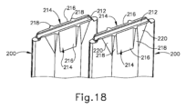
図17~図19は、ステープルカートリッジ(130)と共に使用するように構成された例示的な別のステープルドライバ(200)の対を示している。ステープルカートリッジ(200)は、以下に述べる点を除いて、上記に述べたステープルカートリッジ(180)と同様である。ステープルドライバ(180)と同様、ステープルドライバ(200)は、ステープルドライバ(200)が互い違いの構成で配置されるように、ステープルドライバ(200)をそれらの下端(206)において相互接続するブリッジ要素(202)を有するドライバユニット(201)として一体に形成されている。更に、各ステープルドライバ(200)は、上端(204)、下端(204)、第1の側面(208)、反対側の第2の側面(210)、上端(204)における溝(212)、及びその高さに沿って横断方向に細長い八角形の形状を有している。 17-19 show another exemplary pair of staple drivers (200) configured for use with staple cartridge (130). Staple cartridge (200) is similar to staple cartridge (180) described above, except as described below. Like staple driver (180), staple drivers (200) are integrally formed as a driver unit (201) having bridge elements (202) interconnecting staple drivers (200) at their lower ends (206) such that staple drivers (200) are arranged in a staggered configuration. Additionally, each staple driver (200) has a top end (204), a bottom end (204), a first side (208), an opposing second side (210), a groove (212) at the top end (204), and a transversely elongated octagonal shape along its height.
ステープルドライバ(180)と異なり、ステープルドライバ(200)の各側面(208、210)は、ステープル(170)の形成時にステープル脚部(174)を受容するように構成された単一のポケット(194)を含む。各ポケット(194)は、上部溝(212)に対して中央に位置付けられており、その上端において溝(212)に向かって角度付けされた対応する面取り面(216)によって画定されている。各面取り面(216)は、一対のボス(218)によってその2つの側面で境界が与えられており、各ボス(218)は、溝(212)の長さに沿って上部溝(212)の中心から等距離だけオフセットされている。各ボス(218)は、対応するポケット(194)のそれぞれの側壁を画定し、ボス(218)は、ほぼ長方形の形状を有する各面取り面(216)を与えるような形状となっている。更に、各ボス(218)は、上端(204)に向かう方向にその高さに沿ってテーパするように、面取りされた側面を有している。ステープルドライバ(200)の各側面(208、210)は、ボス(218)の外側側面に当接し、それぞれの面取り面(216)と同一平面上にある三角形の面(220)を画定する一対の側部リリーフカットを更に含む。 Unlike staple driver (180), each side (208, 210) of staple driver (200) includes a single pocket (194) configured to receive a staple leg (174) during formation of staple (170). Each pocket (194) is centrally positioned relative to upper groove (212) and is defined at its upper end by a corresponding chamfered surface (216) angled toward groove (212). Each chamfered surface (216) is bounded on two sides by a pair of bosses (218), each of which is offset an equal distance from the center of upper groove (212) along the length of groove (212). Each boss (218) defines a respective sidewall of a corresponding pocket (194), and the bosses (218) are shaped to provide each chamfered surface (216) with a generally rectangular shape. Additionally, each boss (218) has chamfered sides that taper along its height in a direction toward the top end (204). Each side (208, 210) of the staple driver (200) further includes a pair of side relief cuts that abut the outer side of the boss (218) and define triangular surfaces (220) that are coplanar with the respective chamfered surfaces (216).
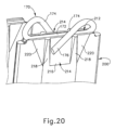
図20に示されるように、各ポケット(194)は、アンビルプレート(72)のステープル形成ポケット(74)によるステープルの3D形成時にステープル(170)のそれぞれの脚先端部(176)を受容するように構成されている。ステープルドライバ(180)のポケット(194a、194b)と同様、ステープルドライバ(200)のポケット(214)は、脚先端部(176)が面取り面(216)と対面するように(ただし、必ずしも接触はしない)、ステープルの脚先端部(176)を受容するように構成されている。したがって、ステープルドライバ(200)は、例えばおよそ0.035インチ~0.040インチの形成後のステープル高さが望ましい比較的薄い組織のような組織中でのステープル(170)の適正な3D形成を促すように構成されている。 As shown in FIG. 20, each pocket (194) is configured to receive a respective leg tip (176) of the staple (170) during 3D formation of the staples by the staple forming pockets (74) of the anvil plate (72). Similar to the pockets (194a, 194b) of the staple driver (180), the pockets (214) of the staple driver (200) are configured to receive the leg tips (176) of the staples such that the leg tips (176) face (but do not necessarily contact) the chamfered surface (216). Thus, the staple driver (200) is configured to facilitate proper 3D formation of the staples (170) in tissue, such as relatively thin tissue where a formed staple height of approximately 0.035 inches to 0.040 inches is desired.
III.線状外科用ステープラの発射ロックアウトばねの塑性変形を最小限に抑制するための例示的な機構
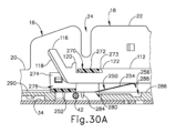
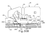
上記に述べたように、線状外科用ステープラ(10)の発射アセンブリ(100)は、近位ホーム位置(図5Dを参照)から遠位発射位置(図5Eを参照)へとカートリッジチャネル(16)内で遠位方向に並進可能であることによって、ステープラ半体(12、14)の遠位部分間にクランプされた組織のステープル留め及び切断を同時に行う。下記により詳細に述べるように、カートリッジ半体(12)は、カートリッジ半体(12)の遠位ジョー部分(20)内に未発射(すなわち「未使用」)のステープルカートリッジ(130)が存在しない場合に、ロックアウト状態に向かって発射アセンブリ(100)を付勢するように構成された板ばねの形態の弾性ロックアウト部材(250)を更に含む。未使用のステープルカートリッジ(130)がカートリッジ半体(12)内に着座されるとき、ロックアウトばね(250)はステープルカートリッジ(130)の展開されたスイングタブ(144)によって下方に偏向され、それにより、発射アセンブリ(100)を発射状態に移行させる。発射状態では、発射アセンブリ(100)は偏向状態のロックアウトばね(250)上を遠位方向に自由に作動可能であり、それによりステープラ(10)を発射する。発射の完了後、発射アセンブリ(100)をそのホーム位置に近位方向に後退させることでロックアウトばね(250)をその初期状態に復帰させ、使用済みステープルカートリッジ(130)が未使用のステープルカートリッジ(130)に交換されるまで発射アセンブリ(100)をロックアウト状態に付勢することができる。
III. Exemplary Mechanisms for Minimizing Plastic Deformation of a Firing Lockout Spring of a Linear Surgical Stapler As discussed above, the firing assembly (100) of the linear surgical stapler (10) is translatable distally within the cartridge channel (16) from a proximal home position (see FIG. 5D) to a distal fired position (see FIG. 5E) to simultaneously staple and sever tissue clamped between the distal portions of the stapler halves (12, 14). As described in more detail below, the cartridge half (12) further includes a resilient lockout member (250) in the form of a leaf spring configured to bias the firing assembly (100) toward a locked state when an unfired (i.e., "unused") staple cartridge (130) is not present within the distal jaw portion (20) of the cartridge half (12). When an unused staple cartridge (130) is seated within cartridge half (12), lockout spring (250) is biased downwardly by deployed swing tabs (144) of staple cartridge (130), thereby transitioning firing assembly (100) to the fired state. In the fired state, firing assembly (100) is free to actuate distally on biased lockout spring (250), thereby firing stapler (10). After firing is completed, firing assembly (100) can be retracted proximally to its home position, returning lockout spring (250) to its initial state and biasing firing assembly (100) to the locked state until the spent staple cartridge (130) is replaced with an unused staple cartridge (130).
発射アセンブリ(100)は、発射ストローク中に遠位方向に作動されると、ロックアウトばね(250)をカートリッジチャネル(16)の床に向かって押し込む。場合によっては、この押し込みによってロックアウトばね(250)の塑性変形が生じる場合があり、これにより、ロックアウトばね(250)がその後のステープラ(10)の発射時に効果的に動作する能力を不要に妨げる可能性がある。したがって、そのような塑性変形のリスクを最小限に抑える機構をステープラ(10)のカートリッジ半体(12)に設けることが望ましい場合がある。 When the firing assembly (100) is actuated distally during the firing stroke, it compresses the lockout spring (250) toward the floor of the cartridge channel (16). In some cases, this compression can cause plastic deformation of the lockout spring (250), which can unnecessarily impede the ability of the lockout spring (250) to operate effectively upon subsequent firing of the stapler (10). Therefore, it may be desirable to provide a mechanism in the cartridge half (12) of the stapler (10) that minimizes the risk of such plastic deformation.
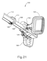
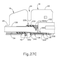
図21に示されるように、発射アセンブリ(100)の摺動ブロック(102)の下面は、摺動ブロック(102)の遠位端に開口し、近位方向に延在する第1の凹部(124)を含む。更に、ブリッジ要素(114)の下面は、ブリッジ要素(114)の軸方向厚さ全体にわたって延在する第2の凹部(126)を含む。下記に述べるように、これらの下面の凹部(124、126)は、発射アセンブリ(100)が完全な発射状態へと遠位方向に作動されるときにロックアウトばね(250)の一部分を受容するように構成されており、それにより、発射ストローク中にロックアウトばね(250)が偏向させられる量を低減する助けとなる。 As shown in FIG. 21, the underside of the sliding block (102) of the firing assembly (100) includes a first recess (124) that opens to the distal end of the sliding block (102) and extends proximally. Additionally, the underside of the bridge element (114) includes a second recess (126) that extends through the entire axial thickness of the bridge element (114). As described below, these underside recesses (124, 126) are configured to receive a portion of the lockout spring (250) when the firing assembly (100) is actuated distally to the fully fired state, thereby helping to reduce the amount that the lockout spring (250) is deflected during the firing stroke.
A.線状外科用ステープラの例示的な発射ロックアウトシステム
図22~図24に示されるように、線状外科用ステープラ(10)のカートリッジ半体(12)は、ガイドブロック(230)(「スペーサブロック」とも呼ばれる)及びロックアウトばね(250)を含む発射ロックアウトシステムを備える。ガイドブロック(230)は、ガイドブロック(230)内に形成された開口部を通って横方向に延びるクランプレバー枢動ピン(42)を介して遠位スロット(24)と概ね整列するようにしてカートリッジチャネル(16)の床(34)に固定されている。
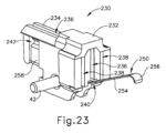
A. Exemplary Firing Lockout Systems for a Linear Surgical Stapler As shown in Figures 22-24, the cartridge half (12) of the linear surgical stapler (10) includes a firing lockout system including a guide block (230) (also referred to as a "spacer block") and a lockout spring (250). The guide block (230) is secured to the floor (34) of the cartridge channel (16) in general alignment with the distal slot (24) via a clamp lever pivot pin (42) that extends laterally through an opening formed in the guide block (230).
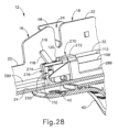
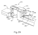
図23に示されるように、ガイドブロックは、第1の横幅を有する近位本体部分(232)と、より狭い第2の幅を有する遠位本体部分(234)とを含む。中央スロット(236)が、ガイドブロック(230)の中心線に沿って近位本体部分及び遠位本体部分(232、234)を通って長手方向に延び、内部を通る発射アセンブリ(100)の中央ビーム(112)を摺動可能に受容するように構成されている。図22に示されるように、中央スロット(236)の遠位部分は、遠位本体部分(234)の上面を通って開口し、ナイフ部材(116)を摺動可能に受容するように構成されている。一対の側部スロット(238)が中央スロット(236)の両側に沿って近位本体部分(232)を通って長手方向に延びており、内部を通る発射アセンブリ(100)の側部ビーム(108)を摺動可能に受容するように構成されている。図23及び図27A~図27Cに最も分かりやすく示されるように、近位本体部分(232)は、中央スロット(236)の下端に沿って長手方向に延びる下部チャネル(240)を更に含む。下記により詳細に述べられるように、下部チャネル(240)は、ステープラ(10)の発射時に下部チャネル(240)内でのロックアウトばね(250)のベースアーム(252)の上向きの偏向を可能にするのに適した横方向寸法を有するサイズとなっている。遠位本体部分(234)は、ロックアウトばね(250)の一対の遠位アンカークリップ(258)を受容して保持するように構成された横方向の反対側にある一対の凹部(242)を含む。 As shown in FIG. 23, the guide block includes a proximal body portion (232) having a first lateral width and a distal body portion (234) having a second, narrower width. A central slot (236) extends longitudinally through the proximal and distal body portions (232, 234) along a centerline of the guide block (230) and is configured to slidably receive a central beam (112) of the firing assembly (100) therethrough. As shown in FIG. 22, a distal portion of the central slot (236) opens through a top surface of the distal body portion (234) and is configured to slidably receive a knife member (116). A pair of side slots (238) extend longitudinally through the proximal body portion (232) along either side of the central slot (236) and are configured to slidably receive a side beam (108) of the firing assembly (100) therethrough. As best seen in FIGS. 23 and 27A-27C, the proximal body portion (232) further includes a lower channel (240) extending longitudinally along the lower end of the central slot (236). As described in more detail below, the lower channel (240) is sized with a lateral dimension suitable for permitting upward deflection of the base arm (252) of the lockout spring (250) within the lower channel (240) upon firing of the stapler (10). The distal body portion (234) includes a pair of laterally opposed recesses (242) configured to receive and retain a pair of distal anchor clips (258) of the lockout spring (250).
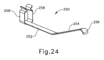
図23に最も分かりやすく示されるように、ロックアウトばね(250)は、平坦なベースアーム(252)と、上向きの角度でベースアーム(252)から近位方向に延び、下向きに湾曲した先端部(256)を有する板ばね(254)の形態で示されている。一対のアンカークリップ(258)が、ベースアーム(252)の遠位端から上方に延びている。図23及び図27A~図27Cに示されるように、アンカークリップ(258)は遠位凹部(242)内で遠位本体部分(234)を把持し、ベースアーム(252)は、遠位本体部分(234)の下面に沿ってクランプレバー枢動ピン(42)を越えて、かつ近位本体部分(232)の下部チャネル(240)を通って延びている。角度付けされたばね脚部(254)が、中央スロット(236)と長手方向に整列して下部チャネル(240)から近位方向に延びている。 As best seen in FIG. 23, the lockout spring (250) is shown in the form of a leaf spring (254) having a flat base arm (252) and a downwardly curved tip (256) extending proximally from the base arm (252) at an upward angle. A pair of anchor clips (258) extend upwardly from the distal end of the base arm (252). As shown in FIGS. 23 and 27A-27C, the anchor clips (258) grip the distal body portion (234) within the distal recess (242), and the base arm (252) extends along the underside of the distal body portion (234), past the clamp lever pivot pin (42), and through the lower channel (240) of the proximal body portion (232). Angled spring legs (254) extend proximally from the lower channel (240) in longitudinal alignment with the central slot (236).
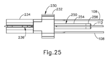
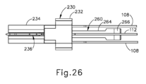
図25及び図27A~図27Cに示されるように、発射アセンブリ(100)の中央ビーム(112)がロックアウトばね(250)のばね脚部(254)上に長手方向に位置付けられており、中央ビーム(112)はばね脚部(254)上でばね脚部と直接接触して並進するように構成されている。図26は、ロックアウトばね(260)がばね脚部(264)の少なくとも中間及び遠位部分よりも幅広の下方に湾曲した近位先端部(266)を含む点以外はロックアウトばね(250)と同様の例示的な代替ロックアウトばね(260)を示す。幅広の先端部(266)は、発射アセンブリ(100)の長手方向の作動の全体を通じて中央ビーム(112)をばね脚部(264)との係合状態に維持するように構成されている。 As shown in FIG. 25 and FIG. 27A-C, the central beam (112) of the firing assembly (100) is longitudinally positioned on the spring legs (254) of the lockout spring (250), and the central beam (112) is configured to translate directly on the spring legs (254). FIG. 26 shows an exemplary alternative lockout spring (260) similar to the lockout spring (250), except that the lockout spring (260) includes a downwardly curved proximal tip (266) that is wider than at least the intermediate and distal portions of the spring legs (264). The wider tip (266) is configured to maintain the central beam (112) in engagement with the spring legs (264) throughout the longitudinal actuation of the firing assembly (100).
図27Aに示されるように、カートリッジチャネル(16)からの未使用のステープルカートリッジ(130)が存在していない場合、ばね脚部(254)は中心ビーム(112)を弾性的に上方に付勢し、それにより、中央ビーム(112)のロックアウト突起(122)がガイドブロック(230)の近位面(233)と係合する。この係合により、中央ビーム(112)はガイドブロック(230)に対して長手方向にロックされ、したがって発射アセンブリ(100)の遠位方向への並進が妨げられる。図27Bは、カートリッジチャネル(16)内に未使用のステープルカートリッジ(130)が着座される際に、中央ビーム(112)がカートリッジチャネルの床(34)に向かって下方に枢動される様子を示している。図27B及び図30Bにおいて、未使用のステープルカートリッジ(130)は、展開位置にあるスイングタブ(144)の概略的描写によって示されている点は理解されよう。上記に述べたように、展開位置にあるスイングタブ(144)は、ステープルカートリッジ(130)のナイフスロット(142)を横断方向にわたって延びている。したがって、カートリッジチャネル(16)内に未使用のステープルカートリッジ(130)が着座されることで、スイングタブ(144)がナイフ部材(116)と係止要素(120)との間で中央ビーム(112)の上面と係合して、中央ビーム(112)を下方に駆動して発射状態の発射アセンブリ(100)を与える。このように、カートリッジチャネル(16)内に未使用のステープルカートリッジ(130)が着座されると、ロックアウトばね(250)のばね脚部(254)がカートリッジの床(34)に向かって下方に圧縮される。 As shown in FIG. 27A, in the absence of an unused staple cartridge (130) from the cartridge channel (16), the spring legs (254) resiliently bias the central beam (112) upward, causing the lockout projection (122) of the central beam (112) to engage the proximal face (233) of the guide block (230). This engagement locks the central beam (112) longitudinally relative to the guide block (230), thus preventing distal translation of the firing assembly (100). FIG. 27B illustrates how the central beam (112) is pivoted downward toward the cartridge channel floor (34) when an unused staple cartridge (130) is seated within the cartridge channel (16). It will be appreciated that in FIGS. 27B and 30B, an unused staple cartridge (130) is illustrated by a schematic depiction of the swing tab (144) in the deployed position. As described above, the swing tab (144) in the deployed position extends across the knife slot (142) of the staple cartridge (130). Thus, with an unused staple cartridge (130) seated in the cartridge channel (16), the swing tab (144) engages the upper surface of the central beam (112) between the knife member (116) and the locking element (120) to drive the central beam (112) downward to provide the firing assembly (100) in a fired state. Thus, with an unused staple cartridge (130) seated in the cartridge channel (16), the spring leg (254) of the lockout spring (250) is compressed downward toward the cartridge floor (34).
図27Cに示されるように、次いで、発射状態の発射アセンブリ(100)が、摺動ブロック(102)のアクチュエータ(104、106)によって遠位方向に駆動される(図4を参照)。これにより、発射ビーム(108、112)が押されてガイドブロック(230)を通ってステープルカートリッジ(130)内へと遠位方向に並進し、それによりステープルドライバ(180)が上方に作動されてステープル(170)を組織内に打ち込み、同時にナイフ部材(116)によって組織を切断する。発射アセンブリ(100)が図27Cに示される完全発射位置に向かってばね脚部(254)を越えて遠位方向に前進すると、ばね脚部(254)がブリッジ要素(114)の下面凹部(126)を通ってかつ摺動ブロック(102)の下面凹部(124)内に受容される。更に、ばねアーム先端部(256)がカートリッジチャネルの床(34)に形成された開口部(36)内に受容される。同時に、ロックアウトばね(250)のベースアーム(252)がガイドブロック(230)の下部チャネル(240)内で弾性的に上方に偏向できるようになるが、これは、ばね脚部(254)が、発射アセンブリ(100)の下面凹部(124、126)内で必要なだけ長手方向に摺動できることにもよる。このようにして、ロックアウトばね(250)は、発射アセンブリ(100)の完全発射状態におけるロックアウトばねの塑性変形を最小限に抑える、偏向状態をとることができる。 As shown in FIG. 27C, the fired firing assembly (100) is then driven distally by the actuators (104, 106) of the sliding block (102) (see FIG. 4). This pushes the firing beams (108, 112) to translate distally through the guide block (230) and into the staple cartridge (130), thereby actuating the staple driver (180) upwardly to drive the staples (170) into tissue while simultaneously severing the tissue with the knife member (116). As the firing assembly (100) advances distally over the spring legs (254) toward the fully fired position shown in FIG. 27C, the spring legs (254) are received through the underside recesses (126) of the bridge element (114) and into the underside recesses (124) of the sliding block (102). Additionally, the spring arm tip (256) is received within an opening (36) formed in the floor (34) of the cartridge channel. At the same time, the base arm (252) of the lockout spring (250) is allowed to resiliently bias upward within the lower channel (240) of the guide block (230) while the spring leg (254) is allowed to slide longitudinally as required within the lower recesses (124, 126) of the firing assembly (100). In this manner, the lockout spring (250) is allowed to assume a biased state that minimizes plastic deformation of the lockout spring in the fully fired state of the firing assembly (100).
B.例示的な代替的発射ロックアウトシステム
場合によっては、上記の代わりに、上記に述べたガイドブロック(230)を、線状外科用ステープラ(10)が発射されるときのロックアウトばね(250)の塑性変形を低減するのに適した他の形で構成することが望ましい場合がある。図28~図30Cは、下記に述べる点を除いて、上記に述べたガイドブロック(230)と同様の例示的な代替的ガイドブロック(270)(又は「スペーサブロック」)を備えたカートリッジ半体(12)を示している。この点に関し、ガイドブロック(270)を、ロックアウトばね(250)と共働するガイドブロック(230)及び上記に述べたカートリッジ半体(12)の他の構成要素に置き換えることにより、線状外科用ステープラ(10)の発射ロックアウトシステムを規定することができる点は理解されよう。
B. Exemplary Alternative Firing Lockout Systems In some cases, it may be desirable to alternatively configure the above-described guide block (230) in other manners suitable for reducing plastic deformation of the lockout spring (250) when the linear surgical stapler (10) is fired. Figures 28-30C illustrate a cartridge half (12) with an exemplary alternative guide block (270) (or "spacer block") similar to the above-described guide block (230), except as described below. In this regard, it will be appreciated that a firing lockout system for the linear surgical stapler (10) can be defined by replacing the guide block (270) with the guide block (230) and other components of the cartridge half (12) described above that cooperate with the lockout spring (250).
ガイドブロック(270)は、カートリッジチャネルの床(34)に固定されており、第1の横幅を有する近位本体部分(272)、より狭い第2の幅を有する遠位本体部分(274)、近位本体部分及び遠位本体部分(272、274)を通って長手方向に延びる中央スロット(276)、並びに中央スロット(276)の両側に沿って近位本体部分(272)を通って長手方向に延びる一対の側部スロット(278)を有している。近位本体部分(272)は、中央スロット(276)の下端に沿って長手方向に延びる下部チャネル(280)を更に含む。遠位本体部分(274)は、ロックアウトばね(250)の遠位アンカークリップ(258)を受容して保持するように構成された横方向の反対側にある一対の凹部(282)を含む。 The guide block (270) is secured to the cartridge channel floor (34) and has a proximal body portion (272) having a first lateral width, a distal body portion (274) having a second narrower width, a central slot (276) extending longitudinally through the proximal and distal body portions (272, 274), and a pair of side slots (278) extending longitudinally through the proximal body portion (272) along either side of the central slot (276). The proximal body portion (272) further includes a lower channel (280) extending longitudinally along a lower end of the central slot (276). The distal body portion (274) includes a pair of laterally opposed recesses (282) configured to receive and retain the distal anchor clip (258) of the lockout spring (250).
図30Aに示されるように、近位本体部分(272)は、クランプレバー枢動ピン(42)の近位側において下部チャネル(280)の両側の壁から横方向内側に突出する一対のばね支持要素(284)を含む。ロックアウトばね(250)のベースアーム(252)が下部チャネル(240)を通って長手方向に延びており、そのため、ベースアーム(252)はクランプレバー枢動ピン(42)及びばね支持要素(284)と接触して、それらによって垂直方向に支持されている。 As shown in FIG. 30A, the proximal body portion (272) includes a pair of spring support elements (284) that project laterally inward from opposing walls of the lower channel (280) proximal to the clamp lever pivot pin (42). A base arm (252) of the lockout spring (250) extends longitudinally through the lower channel (240) such that the base arm (252) contacts and is vertically supported by the clamp lever pivot pin (42) and the spring support elements (284).
細長い近位部材(286)がガイドブロック(270)の近位本体部分(272)に一体に接合されており、カートリッジチャネル(16)の近位フレーム部分(18)内のカートリッジチャネルの床(34)に沿って近位方向に延びている。細長近位部材(286)の上面は、下部チャネル(280)と連通して、ステープラ(10)の発射時にロックアウトばね(250)のばね脚部(254)が下方に偏向される際にその内部にばね脚部(254)を受容するように構成された細長凹部(288)を有している。細長近位部材(286)の近位端は、カートリッジチャネルの床(34)の開口部を通って下方に突出するユーザ把持機構(図示せず)を含むことができる。かかるユーザ把持機構は、ユーザの指の支点として機能するように構成することができ、それにより、ユーザは同じ方の手の対応する親指を使用して、上記に述べた保持アセンブリ(80)の解放ボタン(90)を遠位方向に押し込むことができる。 An elongated proximal member (286) is integrally joined to the proximal body portion (272) of the guide block (270) and extends proximally along the cartridge channel floor (34) in the proximal frame portion (18) of the cartridge channel (16). An upper surface of the elongated proximal member (286) has an elongated recess (288) in communication with the lower channel (280) and configured to receive therein the spring leg (254) of the lockout spring (250) as the spring leg (254) is biased downwardly upon firing of the stapler (10). The proximal end of the elongated proximal member (286) can include a user gripping mechanism (not shown) that projects downwardly through an opening in the cartridge channel floor (34). Such a user gripping mechanism may be configured to act as a fulcrum for the user's fingers, allowing the user to use the corresponding thumb of the same hand to distally depress the release button (90) of the retention assembly (80) described above.
細長い遠位部材(290)がガイドブロック(270)の遠位本体部分(274)に一体に接合されており、カートリッジチャネル(16)の遠位ジョー部分(20)内のカートリッジチャネルの床(34)に沿って遠位方向に延びている。細長い遠位部材(290)の遠位端は、カートリッジチャネル(16)の遠位ジョー部分(20)に対して細長い遠位部材(290)を軸方向に固定するように構成された機械的接地機構(図示せず)を含むことができる。図30A~図30Cに示され、下記に述べるように、発射アセンブリ(100)は、細長い近位部材及び遠位部材(286、290)上をガイドブロック(270)を通って並進するように構成されている。 An elongated distal member (290) is integrally joined to the distal body portion (274) of the guide block (270) and extends distally along the cartridge channel floor (34) within the distal jaw portion (20) of the cartridge channel (16). The distal end of the elongated distal member (290) may include a mechanical grounding mechanism (not shown) configured to axially secure the elongated distal member (290) relative to the distal jaw portion (20) of the cartridge channel (16). As shown in FIGS. 30A-30C and described below, the firing assembly (100) is configured to translate over the elongated proximal and distal members (286, 290) through the guide block (270).
図30Aに示されるように、カートリッジチャネル(16)からの未使用のステープルカートリッジ(130)が存在していない場合、ばね脚部(254)は中心ビーム(112)を弾性的に上方に付勢し、そのため、中央ビーム(112)のロックアウト突起(122)がガイドブロック(270)の近位本体部分(272)の近位面(273)と係合する。この係合により発射アセンブリ(100)は、図27A~図27Cに関連して上記に述べたものと同様のロックアウト状態となる。図30Bは、カートリッジチャネル(16)内に未使用のカートリッジ(130)が着座されたときに未使用のステープルカートリッジ(130)の展開されたスイングタブ(144)によって中央ビーム(112)が細長い近位部材(286)に向かって下方に枢動されている様子を示しており、これにより発射アセンブリ(100)が発射状態となっている。未使用のステープルカートリッジ(130)が着座されると、ロックアウトばね(250)のばね脚部(254)も細長い近位部材(286)に向かって下方に圧縮される。 As shown in FIG. 30A, in the absence of an unused staple cartridge (130) from the cartridge channel (16), the spring legs (254) resiliently bias the central beam (112) upwardly, such that the lockout projections (122) of the central beam (112) engage the proximal surface (273) of the proximal body portion (272) of the guide block (270). This engagement places the firing assembly (100) in a locked out state similar to that described above in connection with FIGS. 27A-27C. FIG. 30B illustrates how the central beam (112) is pivoted downwardly toward the elongated proximal member (286) by the deployed swing tabs (144) of the unused staple cartridge (130) when seated in the cartridge channel (16), thereby placing the firing assembly (100) in a fired state. When the unused staple cartridge (130) is seated, the spring legs (254) of the lockout spring (250) are also compressed downward toward the elongated proximal member (286).
図30Cに示されるように、次に発射状態の発射アセンブリ(100)が遠位方向に駆動され、これにより発射ビーム(108、112)が押されてガイドブロック(270)を通ってステープルカートリッジ(130)内へと遠位方向に並進し、それによりステープルドライバ(180)が上方に作動されてステープル(170)を組織内に打ち込み、同時にナイフ部材(116)によって組織を切断する。発射アセンブリ(100)が図30Cに示される完全発射位置に向かってばね脚部(254)を越えて遠位方向に前進すると、図27A~図27Cに関連して上記に述べたのと同様の要領で、ばね脚部(254)がブリッジ要素(114)の下面凹部(126)を通って摺動ブロック(102)の下面凹部(124)内に受容される。更に、ばね脚部(254)及びその近位先端部(256)が細長い近位部材(286)の細長凹部(288)内に受容される。同時に、図30に示されるように、ロックアウトばね(250)のベースアーム(252)の中間部分がクランプレバー枢動ピン(42)及びばね支持要素(284)の一方又は両方によって垂直方向に支持される一方で、ベースアーム(252)の近位部分はガイドブロック(270)の下部チャネル(280)内で弾性的に偏向することができる。このようにして、ロックアウトばね(250)は、発射アセンブリ(100)の完全発射状態におけるロックアウトばねの塑性変形を最小限に抑える、偏向状態をとることができる。 As shown in FIG. 30C, the fired firing assembly (100) is then driven distally, which pushes and translates the firing beams (108, 112) distally through the guide block (270) and into the staple cartridge (130), thereby actuating the staple driver (180) upwardly to drive the staples (170) into tissue while simultaneously severing the tissue with the knife member (116). As the firing assembly (100) advances distally over the spring legs (254) toward the fully fired position shown in FIG. 30C, the spring legs (254) are received through the underside recesses (126) of the bridge element (114) and into the underside recesses (124) of the slide block (102), in a manner similar to that described above in connection with FIGS. 27A-27C. Further, the spring leg (254) and its proximal tip (256) are received in the elongated recess (288) of the elongated proximal member (286). At the same time, as shown in FIG. 30, the intermediate portion of the base arm (252) of the lockout spring (250) is vertically supported by one or both of the clamp lever pivot pin (42) and the spring support element (284), while the proximal portion of the base arm (252) can be elastically biased within the lower channel (280) of the guide block (270). In this manner, the lockout spring (250) can assume a biased state that minimizes plastic deformation of the lockout spring in the fully fired state of the firing assembly (100).
IV.形成後ステープルの均一な高さを促すための例示的な機構
場合によっては、クランプレバー(40)の閉鎖によってカートリッジ半体(12)に対して線状外科用ステープラ(10)のアンビル半体(14)がクランプされると、アンビルチャネル(60)の遠位ジョー部分(64)がカートリッジ半体(12)に対してその長さに沿って変形する可能性がある。より詳細には、そのような変形により、アンビルプレート(72)及び遠位ジョー部分(64)の対応する側壁取り付け面が、例えば、説明の目的で遠位ジョー部分(64)の曲率を誇張して示す図34に示されるように、カートリッジ半体(12)のステープルカートリッジデッキ(140)に対して凸状の曲率をとる。その結果、ステープルカートリッジデッキ(140)とアンビルプレート(72)との間に形成される長手方向に延びる組織隙間は、ステープルカートリッジ(130)及びアンビルプレート(72)の長さに沿ってそのサイズが一貫しなくなる可能性がある。詳細には、組織隙間は、例えば図34に示されるように、ステープルカートリッジ(130)及びアンビルプレート(72)の中間位置でより小さくなり、ステープルカートリッジ(130)及びアンビルプレート(72)の近位端の位置及び遠位端の位置でより大きくなる可能性がある。組織間隙サイズのこのような非一貫性によって、クランプされた組織内に形成されるステープル(170)の高さが一貫しなくなる可能性があり、望ましくない。したがって、アンビル半体(14)及び/又はカートリッジ半体(12)が、このようなアンビルチャネル(60)の偏向に適合し、ステープルカートリッジ(130)及びアンビルプレート(72)の長さに沿ったステープル(170)の形成後高さの一貫性を確実とする機構を備えることが望ましい場合がある。
IV. Exemplary Mechanisms for Promoting Uniform Formed Staple Height In some cases, when the anvil half (14) of the linear surgical stapler (10) is clamped against the cartridge half (12) by closure of the clamp lever (40), the distal jaw portion (64) of the anvil channel (60) can deform along its length relative to the cartridge half (12). More specifically, such deformation can cause the anvil plate (72) and corresponding sidewall mounting surfaces of the distal jaw portion (64) to assume a convex curvature relative to the staple cartridge deck (140) of the cartridge half (12), as shown, for example, in FIG. 34, which illustrates an exaggerated curvature of the distal jaw portion (64) for illustrative purposes. As a result, the longitudinally extending tissue gap formed between the staple cartridge deck (140) and the anvil plate (72) can be inconsistent in size along the length of the staple cartridge (130) and the anvil plate (72). In particular, the tissue gap may be smaller at an intermediate location of the staple cartridge (130) and anvil plate (72) and larger at the proximal and distal ends of the staple cartridge (130) and anvil plate (72), as shown, for example, in FIG. 34. Such inconsistencies in tissue gap size may result in inconsistent heights of staples (170) formed in the clamped tissue, which may be undesirable. Accordingly, it may be desirable for the anvil half (14) and/or cartridge half (12) to include features that accommodate such deflections of the anvil channel (60) and ensure consistency in the formed height of staples (170) along the length of the staple cartridge (130) and anvil plate (72).
A.湾曲したアンビルプレートを有する例示的なアンビル半体
図31~図33Bは、以下に述べる点を除いて、上記に述べたアンビル半体(14)と同様である例示的な別のアンビル半体(300)を示している。図31に示されるように、アンビル半体(300)は、アンビルプレート(308)が取り付けられる一対の凹状湾曲取り付け面(306)を画定する一対の側壁を備えた遠位ジョー部分(304)を有するアンビルチャネル(302)を含む。アンビルプレート(308)自体がアンビルチャネル(302)の凹状湾曲取り付け面(306)に形状が一致しているため、取り付け面(306)及びアンビルプレート(308)は同じ凹状湾曲経路に沿って長手方向に延びている。
A. Exemplary Anvil Half with a Curved Anvil Plate Figures 31-33B show another exemplary anvil half (300) that is similar to the anvil half (14) described above, except as noted below. As shown in Figure 31, the anvil half (300) includes an anvil channel (302) having a distal jaw portion (304) with a pair of side walls that define a pair of concavely curved mounting surfaces (306) to which an anvil plate (308) is attached. The anvil plate (308) itself conforms to the concavely curved mounting surfaces (306) of the anvil channel (302) such that the mounting surfaces (306) and the anvil plate (308) extend longitudinally along the same concavely curved path.
いくつかの変形例では、アンビルプレート(308)は、最初に真っ直ぐで平坦な構成で形成された後、アンビル半体(302)の製造時にアンビルチャネル(302)の湾曲取り付け面(306)に対して圧縮されて取り付け面に(例えば溶接により)固定されるときに、湾曲した構成に変形させることができる。他の変形例では、アンビルプレート(308)は、湾曲取り付け面(306)に固定される前に取り付け面(306)と同じ凹状曲率で予め形成することができる。いずれの場合も、湾曲取り付け面(306)、したがってアンビルプレート(308)の凹状曲率は、ステープラ半体(12、300)が互いに完全にクランプされるときに遠位ジョー部分(304)がカートリッジ半体(12)のステープルカートリッジデッキ(140)に対してとることが予想される凸状曲率の逆数として選択される。 In some variations, the anvil plate (308) may be initially formed in a straight, flat configuration and then deformed into a curved configuration when compressed against the curved mounting surface (306) of the anvil channel (302) and secured (e.g., by welding) to the mounting surface during manufacture of the anvil half (302). In other variations, the anvil plate (308) may be preformed with the same concave curvature as the mounting surface (306) before being secured to the curved mounting surface (306). In either case, the concave curvature of the curved mounting surface (306), and therefore the anvil plate (308), is selected as the inverse of the convex curvature that the distal jaw portion (304) is expected to assume relative to the staple cartridge deck (140) of the cartridge half (12) when the stapler halves (12, 300) are fully clamped together.
図31に示されるように、本変形例における取り付け面(306)及びアンビルプレート(308)の凹状曲率は、遠位ジョー部分(304)の長さに沿って不均一である。したがって、遠位ジョー部分(304)とアンビルプレート(308)との組み合わせによって規定される横断方向の高さは、遠位ジョー部分(304)の長さに沿って不均一に異なる。詳細には、図32A~図32Cに示されるように、アンビル半体(302)は、遠位ジョー部分(304)の中間位置で最小の横断方向高さ(H1)を、遠位ジョー部分(304)の遠位端で最大の横断方向高さ(H2)を、遠位ジョー部分(304)の近位端で中間の横方向高さ(H3)を有する。いくつかの他の変形例では、遠位の横断方向高さ及び近位の横断方向高さ(H2、H3)は等しくてもよい。 As shown in FIG. 31, the concave curvature of the mounting surface (306) and the anvil plate (308) in this variation is non-uniform along the length of the distal jaw portion (304). Thus, the transverse height defined by the combination of the distal jaw portion (304) and the anvil plate (308) varies non-uniformly along the length of the distal jaw portion (304). In particular, as shown in FIGS. 32A-32C, the anvil half (302) has a minimum transverse height (H1) at the midpoint of the distal jaw portion (304), a maximum transverse height (H2) at the distal end of the distal jaw portion (304), and an intermediate transverse height (H3) at the proximal end of the distal jaw portion (304). In some other variations, the distal and proximal transverse heights (H2, H3) may be equal.
図33Aは、上記に述べたカートリッジ半体(12)に対して部分的にクランプされた状態にあるアンビル半体(302)を示す。この状態では、アンビルプレート(308)の遠位端は、カートリッジ半体(12)の組織隙間ポスト(146)に対してクランプし始める。一方、アンビル半体(300)のアンビルプレート(308)及び取り付け面(306)は、ステープルカートリッジ(130)のデッキ(140)に対して依然として凹状に湾曲した構成となっている。図33Bに示されるように、クランプレバー(40)がその完全閉鎖位置へと閉鎖されると、アンビルチャネル(302)の遠位ジョー部分(304)がラッチピン(307)の遠位でその長さに沿ってわずかに変形させられる。この変形によって、アンビル半体(302)の取り付け面(306)及びアンビルプレート(308)が平坦化する一方で、同時に遠位ジョー部分(304)の上面(309)に凹状曲率が形成される。その結果、アンビルプレート(308)はカートリッジデッキ(140)に平行に延びることになり、したがって、それらの間にその長さに沿って均一な組織隙間(G)が画定される。この均一な組織隙間(G)は、アンビルプレート(308)及びカートリッジデッキ(140)の長さに沿って均一な高さを有するステープル(170)の形成を促す。 33A shows the anvil half (302) in a partially clamped state against the cartridge half (12) described above. In this state, the distal end of the anvil plate (308) begins to clamp against the tissue gap post (146) of the cartridge half (12), while the anvil plate (308) and mounting surface (306) of the anvil half (300) are still in a concavely curved configuration against the deck (140) of the staple cartridge (130). As shown in FIG. 33B, when the clamp lever (40) is closed to its fully closed position, the distal jaw portion (304) of the anvil channel (302) is slightly deformed along its length distal to the latch pin (307). This deformation flattens the mounting surface (306) of the anvil half (302) and the anvil plate (308) while simultaneously forming a concave curvature on the upper surface (309) of the distal jaw portion (304). As a result, the anvil plate (308) extends parallel to the cartridge deck (140), thus defining a uniform tissue gap (G) therebetween along its length. This uniform tissue gap (G) promotes the formation of staples (170) having a uniform height along the length of the anvil plate (308) and the cartridge deck (140).
B.異なる高さのステープルドライバを有する例示的なステープルカートリッジ
図34は、例示的な別のステープルカートリッジ(310)に対して完全にクランプされた状態にあるアンビルチャネル(60)を概略的に示している。ステープルカートリッジ(310)は、ステープルカートリッジ(310)がステープルカートリッジ(310)の長さに沿って異なる高さ(H1、H2、H3)を有する複数のステープルドライバ(312a、312b、312c)を含む点を除いて、上記に述べたステープルカートリッジ(130)と同様である。詳細には、本変形例では、ステープルカートリッジ(310)の中間部分は最小の高さ(H1)のステープルドライバ(312a)を含み、ステープルカートリッジ(310)の遠位端は最大の高さ(H2)のステープルドライバ(312b)を含み、ステープルカートリッジ(310)の近位端は中間の高さ(H3)のステープルドライバ(312c)を含む。いくつかの他の変形例では、遠位ステープルドライバ及び近位ステープルドライバ(312b、312c)の高さ(H2、H3)は等しくてもよい。図には示されていないが、遠位ドライバ(312b)と中間ドライバ(312a)との間に位置付けられるステープルドライバの高さは、遠位ドライバの高さ(H2)から中間ドライバの高さ(H1)へと徐々に変化させることができることが理解されよう。同様に、中間ドライバ(312a)と近位ドライバ(312c)との間に位置付けられるステープルドライバの高さは、中間ドライバの高さ(H1)から近位ドライバの高さ(H3)へと徐々に変化させることができる。
B. Exemplary Staple Cartridge with Staple Drivers of Different Heights FIG. 34 illustrates a schematic of anvil channel (60) in a fully clamped state relative to another exemplary staple cartridge (310). Staple cartridge (310) is similar to staple cartridge (130) described above, except that staple cartridge (310) includes a plurality of staple drivers (312a, 312b, 312c) having different heights (H1, H2, H3) along the length of staple cartridge (310). Specifically, in this variation, a middle portion of staple cartridge (310) includes staple driver (312a) of a minimum height (H1), a distal end of staple cartridge (310) includes staple driver (312b) of a maximum height (H2), and a proximal end of staple cartridge (310) includes staple driver (312c) of an intermediate height (H3). In some other variations, the heights (H2, H3) of the distal and proximal staple drivers (312b, 312c) may be equal. Although not shown in the figures, it will be appreciated that the height of the staple drivers positioned between the distal driver (312b) and the middle driver (312a) can be gradually changed from the distal driver height (H2) to the middle driver height (H1). Similarly, the height of the staple drivers positioned between the middle driver (312a) and the proximal driver (312c) can be gradually changed from the middle driver height (H1) to the proximal driver height (H3).
図34に示され、また上記に述べたように、アンビルチャネル(60)の遠位ジョー部分(64)は、カートリッジ半体(12)に対してクランプされるときにステープルカートリッジ(310)に向かって凸状に曲がる。その結果、アンビルチャネル(60)の遠位ジョー部分(64)は、その長さに沿ってアンビルプレート(72)とステープルカートリッジ(310)との間に変化する組織隙間を与える湾曲した状態をとる。詳細には、アンビルプレート(72)の中間部分は最小の組織隙間(G1)を画定し、アンビルプレート(72)の遠位端は最大の組織隙間(G2)を画定し、アンビルプレート(72)の近位端は中間の組織隙間(G3)を画定する。異なる高さ(H1、H2、H3)のステープルドライバ(312a、312b、312c)が提供されることで、カートリッジ(310)の中間部分ではより短い距離で、近位及び遠位に向かう方向では徐々に大きな距離でステープル(170)が駆動されることにより、組織隙間(G1、G2、G3)のこのような変動が補正される。その結果、アンビルチャネル(60)の曲率及び組織隙間(G1、G2、G3)の不均一性にもかかわらず、ステープルカートリッジ(310)の全長に沿って均一な高さを有するステープル(170)が形成される。 As shown in FIG. 34 and described above, the distal jaw portion (64) of the anvil channel (60) bends convexly toward the staple cartridge (310) when clamped against the cartridge half (12). As a result, the distal jaw portion (64) of the anvil channel (60) assumes a curved condition that provides a varying tissue gap between the anvil plate (72) and the staple cartridge (310) along its length. In particular, the intermediate portion of the anvil plate (72) defines a minimum tissue gap (G1), the distal end of the anvil plate (72) defines a maximum tissue gap (G2), and the proximal end of the anvil plate (72) defines an intermediate tissue gap (G3). Providing staple drivers (312a, 312b, 312c) of different heights (H1, H2, H3) compensates for such variations in tissue gaps (G1, G2, G3) by driving the staples (170) at shorter distances in the middle of the cartridge (310) and gradually greater distances in the proximal and distal directions. As a result, staples (170) are formed with a uniform height along the entire length of the staple cartridge (310) despite the curvature of the anvil channel (60) and non-uniformities in the tissue gaps (G1, G2, G3).
V.例示的な組み合わせ
以下の実施例は、本明細書の教示を組み合わせるか又は適用することができる、種々の非網羅的な方法に関する。以下の実施例は、本出願における又は本出願の後の書類提出における任意の時点で提示され得るいずれの特許請求の適用範囲をも限定することを意図したものではないことを理解されたい。一切の権利放棄を意図するものではない。以下の実施例は、あくまでも例示的な目的で与えられるものに過ぎない。本明細書の種々の教示は、その他の多くの方式で構成及び適用が可能であると考えられる。また、いくつかの変形形態では、以下の実施例において言及される特定の特徴を省略してよいことも考えられる。したがって、本発明者らによって又は本発明者らの利益の承継者によって、後日そうである旨が明示的に示されない限り、以下に言及される態様又は特徴のいずれも重要なものとしてみなされるべきではない。いずれの特許請求が、本出願において、又は以下に言及される特徴以外の更なる特徴を含む本出願に関連する後の書類提出において示される場合、それらの更なる特徴は、特許性に関連するいかなる理由によっても追加されたものとして仮定されるべきではない。
V. Exemplary Combinations The following examples relate to various non-exhaustive methods in which the teachings herein may be combined or applied. It should be understood that the following examples are not intended to limit the scope of any claims that may be presented at any time in this application or in a later filing of this application. No disclaimer is intended. The following examples are provided for illustrative purposes only. It is contemplated that the various teachings herein may be configured and applied in many other ways. It is also contemplated that certain features mentioned in the following examples may be omitted in some variations. Thus, none of the aspects or features mentioned below should be considered as critical unless expressly indicated to be so at a later date by the inventors or by the inventors' successors in interest. If any claim is presented in this application or in a later filing related to this application that includes additional features other than those mentioned below, those additional features should not be presumed to have been added for any reason related to patentability.
外科用ステープラと共に使用するように構成されたステープルカートリッジであって、(a)カートリッジ本体と、(b)カートリッジ本体によって画定されるデッキであって、外科用ステープラのアンビルに対して組織を圧縮するように構成されている、デッキと、(c)デッキ内に形成された複数のステープル開口部と、(d)ステープル開口部内に配設された複数のステープルであって、ステープルのそれぞれが、一対の脚部を含む、複数のステープルと、(e)ステープル開口部内に配設されたステープルドライバであって、ステープルを組織を通してかつアンビルに対して打ち込んで脚部を形成するように作動可能であり、ステープルドライバのそれぞれが、(i)ドライバ本体と、(ii)ドライバ本体の第1の側面上に配設された第1のポケットと、(iii)ドライバ本体の第2の側面上に配設された第2のポケットと、を含み、第1のポケット及び第2のポケットは、脚部がアンビルに対して形成されるときにそれぞれのステープルの脚部を受容するように構成されている、複数のステープルドライバと、を備える、ステープルカートリッジ。 A staple cartridge configured for use with a surgical stapler, comprising: (a) a cartridge body; (b) a deck defined by the cartridge body, the deck configured to compress tissue against an anvil of the surgical stapler; (c) a plurality of staple openings formed in the deck; (d) a plurality of staples disposed in the staple openings, each of the staples including a pair of legs; and (e) a plurality of staple drivers disposed in the staple openings, operable to drive the staples through the tissue and against the anvil to form the legs, each of the staple drivers including: (i) a driver body; (ii) a first pocket disposed on a first side of the driver body; and (iii) a second pocket disposed on a second side of the driver body, the first pocket and the second pocket configured to receive the legs of a respective staple when the legs are formed against the anvil.
第1のポケット及び第2のポケットが、ドライバ本体の上端に開口している、実施例1に記載のステープルカートリッジ。 A staple cartridge as described in Example 1, in which the first pocket and the second pocket open to the upper end of the driver body.
ステープルドライバのそれぞれが、ドライバ本体の第1の側面上に配設された第1のボスと、ドライバ本体の第2の側面上に配設された第2のボスと、を更に含み、第1のボスが第1のポケットの側壁を画定し、第2のボスが第2のポケットの側壁を画定する、実施例1又は2に記載のステープルカートリッジ。 The staple cartridge of Example 1 or 2, wherein each of the staple drivers further includes a first boss disposed on a first side of the driver body and a second boss disposed on a second side of the driver body, the first boss defining a sidewall of the first pocket and the second boss defining a sidewall of the second pocket.
第1のポケットが、ドライバ本体の第1の側面上の第1の面取り面によって画定され、第2のポケットが、本体の第2の側面上の第2の面取り面によって画定されている、実施例1~3のいずれか1つに記載のステープルカートリッジ。 A staple cartridge according to any one of Examples 1 to 3, wherein the first pocket is defined by a first chamfered surface on a first side of the driver body and the second pocket is defined by a second chamfered surface on a second side of the body.
第1の面取り面及び第2の面取り面の上部部分が、互いに向かって角度付けされている、実施例4に記載のステープルカートリッジ。 The staple cartridge of Example 4, wherein the upper portions of the first chamfered surface and the second chamfered surface are angled toward each other.
デッキ上に配設された複数のスタンドオフ部材を更に備え、スタンドオフ部材が、デッキから離れる方向に突出し、組織と係合するように構成されている、実施例1~5のいずれか1つに記載のステープルカートリッジ。 The staple cartridge according to any one of Examples 1 to 5, further comprising a plurality of standoff members disposed on the deck, the standoff members configured to protrude in a direction away from the deck and engage tissue.
スタンドオフ部材の少なくとも一部のそれぞれが、隣接するステープル開口部の一部分の周囲を包囲する端部分を含む、実施例6に記載のステープルカートリッジ。 The staple cartridge of Example 6, wherein at least some of the standoff members each include an end portion that circumscribes a portion of the adjacent staple opening.
端部分は、ステープルドライバが作動されるときにステープルドライバのそれぞれ1つに対面するように構成された、丸みを帯びた端面を含む、実施例7に記載のステープルカートリッジ。 The staple cartridge of Example 7, wherein the end portions include rounded end faces configured to face respective ones of the staple drivers when the staple drivers are actuated.
スタンドオフ部材が、デッキの遠位端に配設されたランプ機構を含む、実施例6~8のいずれか1つに記載のステープルカートリッジ。 A staple cartridge according to any one of Examples 6 to 8, wherein the standoff member includes a ramp mechanism disposed at the distal end of the deck.
デッキの遠位端に配設されたポストを更に備え、ランプ機構が、ステープルカートリッジの長手方向軸に沿ってポストの遠位方向に、かつポストと長手方向に整列して配置されている、実施例9に記載のステープルカートリッジ。 The staple cartridge of Example 9 further comprises a post disposed at a distal end of the deck, and the ramp mechanism is disposed distal to and longitudinally aligned with the post along the longitudinal axis of the staple cartridge.
(a)デッキ内に形成された細長いスロットであって、内部を通る切断部材を摺動可能に受容するように構成され、ステープル開口部が、細長いスロットと並んで配置されている、細長いスロットと、(b)デッキ上に配設された一対の細長いリブであって、細長いスロットの両側の側面に沿って長手方向に延びる、一対の細長いリブと、を更に備える、実施例1~10のいずれか1つに記載のステープルカートリッジ。 The staple cartridge according to any one of Examples 1 to 10, further comprising: (a) an elongated slot formed in the deck configured to slidably receive a cutting member passing therethrough, the staple opening being aligned with the elongated slot; and (b) a pair of elongated ribs disposed on the deck, the pair of elongated ribs extending longitudinally along opposing sides of the elongated slot.
カートリッジ本体が、長手方向軸に沿って直線状に延びている、実施例1~11のいずれか1つに記載のステープルカートリッジ。 A staple cartridge according to any one of Examples 1 to 11, in which the cartridge body extends linearly along the longitudinal axis.
外科用ステープラであって、(a)アンビルを支持する第1の遠位部分を有する第1のステープラ半体と、(b)第2の遠位部分を有する第2のステープラ半体と、(c)請求項1に記載のステープルカートリッジと、を備え、第2の遠位部分が、ステープルカートリッジを受容するように構成され、第1のステープラ半体と第2のステープラ半体とが互いに解放可能に連結されて、アンビルとステープルカートリッジとの間に組織をクランプするように構成されている、外科用ステープラ。
A surgical stapler comprising: (a) a first stapler half having a first distal portion supporting an anvil; (b) a second stapler half having a second distal portion; and (c) a staple cartridge according to
ステープルのそれぞれは、一対の脚が延出するクラウンを含み、アンビルは、脚部が形成されるときに各ステープルの脚先端部が互いからかつクラウンの両側でクラウンから横方向にオフセットされるように、ステープルの脚部を形成するように構成されている、実施例13に記載の外科用ステープラ。 The surgical stapler of Example 13, wherein each of the staples includes a crown from which a pair of legs extend, and the anvil is configured to form the legs of the staples such that when the legs are formed, the leg tips of each staple are laterally offset from each other and from the crown on either side of the crown.
第2のステープラ半体が、(i)発射アセンブリであって、ステープルドライバを作動させて、ステープル開口部から、組織を通してかつアンビルに対してステープルを打ち込むように遠位方向に選択的に作動可能であり、発射アセンブリの下面が凹部を有する、発射アセンブリと、(ii)弾性部材と、を含み、ステープルカートリッジが第2の遠位部分に存在しないとき、弾性部材は、発射アセンブリをロックアウト状態に付勢し、それにより発射アセンブリの遠位作動を防げるように構成され、ステープルカートリッジが最初に第2の細長い部材の内部に着座されるとき、発射アセンブリは、発射アセンブリが向状態の記弾性部材上を遠位方向に並進可能であり、そのため、弾性部材の一部分が発射アセンブリの凹部内に受容されている、発射状態をとるように構成されている、実施例13又は14に記載の外科用ステープラ。
The surgical stapler according to
第2のステープラ半体が、チャネルを有するガイド部材を更に含み、弾性部材がチャネルを通って長手方向に延び、弾性部材は、発射アセンブリが遠位方向に前進されるときにチャネル内で弾性的に偏向するように構成されている、実施例15に記載の外科用ステープラ。 The surgical stapler of Example 15, wherein the second stapler half further includes a guide member having a channel, the elastic member extending longitudinally through the channel, and the elastic member configured to elastically deflect within the channel when the firing assembly is advanced distally.
外科用ステープラと共に使用するように構成されたステープルカートリッジであって、(a)カートリッジ本体と、(b)カートリッジ本体によって画定されるデッキであって、外科用ステープラのアンビルに対して組織を圧縮するように構成されている、デッキと、(c)デッキ内に形成された複数のステープル開口部と、(d)ステープル開口部内に配設された複数のステープルであって、ステープラのそれぞれが、第1の脚部及び第2の脚部を含む、複数のステープルと、(e)ステープル開口部内に配設された複数のステープルドライバであって、組織を通してかつアンビルに対してステープルを打ち込んで脚部を形成するように作動可能であり、ステープルドライバのそれぞれが、(i)第1の面取り面を有する第1の側面と、(ii)第2の面取り面を有する第2の側面と、を含み、第1の脚部及び第2の脚部がアンビルに対して形成されるときに、第1の面取り面は、対面配置でそれぞれのステープルの第1の脚部を受容するように構成され、第2の面取り面は、対面配置でそれぞれのステープルの第2の脚部を受容するように構成されている、複数のステープルドライバと、を備える、ステープルカートリッジ。 A staple cartridge configured for use with a surgical stapler, comprising: (a) a cartridge body; (b) a deck defined by the cartridge body, the deck configured to compress tissue against an anvil of the surgical stapler; (c) a plurality of staple openings formed in the deck; (d) a plurality of staples disposed within the staple openings, each of the staples including a first leg and a second leg; and (e) a plurality of staple drivers disposed within the staple openings, the plurality of staples configured to drive the staple through the tissue. and a plurality of staple drivers operable to drive staples against the anvil to form the legs, each of the staple drivers including (i) a first side having a first chamfered surface and (ii) a second side having a second chamfered surface, the first chamfered surface configured to receive the first leg of a respective staple in a facing arrangement and the second chamfered surface configured to receive the second leg of a respective staple in a facing arrangement when the first and second legs are formed against the anvil.
ステープルドライバのそれぞれの上端がそれぞれのステープルを支持するように構成され、第1の面取り面及び第2の面取り面が上端まで延びている、実施例17に記載のステープルカートリッジ。 The staple cartridge of Example 17, wherein the upper end of each staple driver is configured to support a respective staple, and the first chamfered surface and the second chamfered surface extend to the upper end.
外科用ステープラであって、(a)アンビルを支持する遠位部分を有する第1の細長い部材と、(b)ステープルカートリッジを受容するように構成された遠位部分を有する第2の細長い部材であって、第1の細長い部材及び第2の細長い部材が、互いに解放可能に連結されて、アンビルとステープルカートリッジとの間に組織をクランプするように構成されている、第2の細長い部材と、(c)第2の細長い部材に固定されたガイド部材と、(d)ガイド部材に固定された弾性部材と、(e)第2の細長い部材と摺動可能に連結された発射アセンブリと、を備え、発射アセンブリの下面が凹部を含み、ガイド部材が、第2の細長い部材に対する発射アセンブリの一部分の並進を案内するように構成され、ステープルカートリッジが第2の細長い部材に存在しないとき、弾性部材は、発射アセンブリをロックアウト状態に付勢し、それにより発射アセンブリの遠位作動を防げるように構成され、未使用のステープルカートリッジが第2の細長い部材の内部に着座されるとき、発射アセンブリは、発射アセンブリが偏向状態の弾性部材上を遠位方向に並進可能であり、そのため、弾性部材の近位端が発射アセンブリの凹部内に受容されている、発射状態をとるように構成されている、外科用ステープラ。 A surgical stapler comprising: (a) a first elongated member having a distal portion that supports an anvil; (b) a second elongated member having a distal portion configured to receive a staple cartridge, the first elongated member and the second elongated member being releasably coupled to one another to clamp tissue between the anvil and the staple cartridge; (c) a guide member secured to the second elongated member; (d) a resilient member secured to the guide member; and (e) a firing assembly slidably coupled to the second elongated member, the lower surface of the firing assembly including a recess. A surgical stapler, the guide member being configured to guide translation of a portion of the firing assembly relative to the second elongated member, the resilient member being configured to bias the firing assembly to a locked out state when a staple cartridge is not present on the second elongated member, thereby preventing distal actuation of the firing assembly, and when an unused staple cartridge is seated within the second elongated member, the firing assembly being configured to assume a fired state in which the firing assembly is distally translatable on the resilient member in a deflected state such that a proximal end of the resilient member is received within a recess in the firing assembly.
弾性部材がガイド部材を通って長手方向に延び、弾性部材は、発射アセンブリが遠位方向に前進されるときにガイド部材内で弾性的に偏向するように構成されている、実施例19に記載の外科用ステープラ。 The surgical stapler of Example 19, wherein the elastic member extends longitudinally through the guide member, and the elastic member is configured to elastically deflect within the guide member when the firing assembly is advanced distally.
VI.その他
本明細書に記載の教示、表現、実施形態、実施例などのうちのいずれか1つ以上を、本明細書に記載の他の教示、表現、実施形態、実施例などのうちのいずれか1つ以上と組み合わせることができる点が理解されるべきである。したがって、上記の教示、表現、実施形態、実施例などは、互いに対して独立して考慮されるべきではない。本明細書の教示を組み合わせることができる種々の好適な方法が、本明細書の教示を考慮することにより当業者には容易に明らかとなるであろう。このような修正及び変形形態は、特許請求の範囲に含まれるものとする。
VI. Other It should be understood that any one or more of the teachings, expressions, embodiments, examples, etc. described herein can be combined with any one or more of the other teachings, expressions, embodiments, examples, etc. described herein. Thus, the above teachings, expressions, embodiments, examples, etc. should not be considered independently of each other. Various suitable ways in which the teachings of this specification can be combined will be readily apparent to those skilled in the art in light of the teachings of this specification. Such modifications and variations are intended to be included within the scope of the claims.
更に、本明細書に記載の教示、表現、実施形態、実施例などのいずれか1つ以上は、2018年2月6日に出願された、発明の名称「Release Mechanism for Linear Surgical Stapler」の米国特許出願第15/889,363号;2018年2月6日に出願された、発明の名称「Lockout Assembly for Linear Surgical Stapler」の米国特許出願第15/889,370号;2018年2月6日に出願された、発明の名称「Features to Align and Close Linear Surgical Stapler」の米国特許出願第15/889,374号;2018年2月6日に出願された、発明の名称「Releasable Coupling Features for Proximal Portions of Linear Surgical Stapler」の米国特許出願第15/889,376号;2018年2月6日に出願された、発明の名称「Firing Lever Assembly for Linear Surgical Stapler」の米国特許出願 第15/889,388号;2018年2月6日に出願された、発明の名称「Clamping Mechanism for Linear Surgical Stapler」の米国特許出願第15/889,390号;2018年8月13日に出願された、発明の名称「Firing System for Linear Surgical Stapler」の米国特許出願第16/102,164号;2018年8月13日に出願された、発明の名称「Clamping Assembly for Linear Surgical Stapler」の米国特許出願第16/102,170号;2018年10月11日に出願された、発明の名称「Anvil Assembly for Linear Surgical Stapler」の米国特許出願第16/157,599号;2018年10月11日に出願された、発明の名称「Closure Assembly for Linear Surgical Stapler」の米国特許出願第16/157,605号;及び/又は2018年10月19日に出願された、発明の名称「Decoupling Mechanism for Linear Surgical Stapler」の米国特許出願第16/165,587号に記載の教示、表現、実施形態、実施例などのいずれか1つ以上と組み合わせることができる。これらの出願のそれぞれの開示は、参照により本明細書に組み込まれる。 Furthermore, any one or more of the teachings, expressions, embodiments, examples, etc. described herein may be implemented in accordance with U.S. patent application Ser. No. 15/889,363, filed Feb. 6, 2018, and entitled "Release Mechanism for Linear Surgical Stapler"; U.S. patent application Ser. No. 15/889,370, filed Feb. 6, 2018, and entitled "Lockout Assembly for Linear Surgical Stapler"; U.S. patent application Ser. No. 15/889,370, filed Feb. 6, 2018, and entitled "Features to Align and Close Linear Surgical Stapler"; U.S. patent application Ser. No. 15/889,374, filed Feb. 6, 2018, entitled "Releasable Coupling Features for Proximal Portions of Linear Surgical Stapler"; U.S. patent application Ser. No. 15/889,376, filed Feb. 6, 2018, entitled "Firing Lever Assembly for Linear Surgical Stapler"; U.S. patent application Ser. No. 15/889,388, filed Feb. 6, 2018, entitled "Clamping Mechanism for Linear Surgical Stapler"; U.S. patent application Ser. No. 15/889,390, entitled "Firing System for Linear Surgical Stapler," filed Aug. 13, 2018; U.S. patent application Ser. No. 16/102,164, entitled "Firing System for Linear Surgical Stapler," filed Aug. 13, 2018; U.S. patent application Ser. No. 16/102,170, entitled "Clamping Assembly for Linear Surgical Stapler," filed Oct. 11, 2018; No. 16/157,599, entitled "Closure Assembly for Linear Surgical Stapler," filed Oct. 11, 2018; and/or U.S. patent application Ser. No. 16/165,587, entitled "Decoupling Mechanism for Linear Surgical Stapler," filed Oct. 19, 2018. The disclosures of each of these applications are incorporated herein by reference.
本明細書に参照により組み込まれると言及されるあらゆる特許、公報、又はその他の開示内容は、全体的に又は部分的に、組み込まれる内容が現行の定義、見解、又は本開示に記載されるその他の開示内容とあくまで矛盾しない範囲でのみ本明細書に組み込まれることを理解されたい。それ自体、また必要な範囲で、本明細書に明瞭に記載される開示内容は、参照により本明細書に組み込まれるあらゆる矛盾する記載に優先するものとする。参照により本明細書に組み込まれると言及されているが、現行の定義、見解、又は本明細書に記載される他の開示内容と矛盾する任意の内容、又はそれらの部分は、組み込まれた内容と現行の開示内容との間に矛盾が生じない範囲においてのみ、組み込まれるものとする。 Any patent, publication, or other disclosure referred to as being incorporated by reference herein, in whole or in part, is to be understood as being incorporated herein only to the extent that the incorporated content does not conflict with current definitions, views, or other disclosures set forth in this disclosure. As such, and to the extent necessary, the disclosures expressly set forth herein shall take precedence over any conflicting statements incorporated herein by reference. Any content, or portions thereof, referred to as being incorporated by reference herein but which conflicts with current definitions, views, or other disclosures set forth herein shall be incorporated only to the extent that no conflict arises between the incorporated content and the current disclosures.
上記の装置の変形例は、医療専門家により行われる従来の治療及び処置における用途のみではなく、ロボット支援された治療及び処置における用途をも有することができる。ほんの一例として、本明細書の種々の教示は、ロボット外科用システム、例えばIntuitive Surgical,Inc.(Sunnyvale,California)によるDAVINCI(商標)システムなどに容易に組み込まれてもよい。 Variations of the above devices may have application in robotic-assisted treatments and procedures as well as in traditional treatments and procedures performed by medical professionals. By way of example only, the various teachings herein may be readily incorporated into robotic surgical systems such as the DAVINCI™ system by Intuitive Surgical, Inc. (Sunnyvale, California).
上述の装置の変形例は、1回の使用後に処分するように設計することができ、又はそれらは、複数回使用するように設計することができる。変形例は、一方又はその両方の場合においても、少なくとも1回の使用後に再利用のために再調整されてもよい。再調整は、装置の分解工程、それに続く特定の部品の洗浄又は交換工程、及びその後の再組み立て工程の、任意の組み合わせを含んでもよい。特に、装置のいくつかの変形例は分解することができ、また、装置の任意の数の特定の部分若しくは部品を、任意の組み合わせで選択的に交換又は取り外してもよい。特定の部品の洗浄及び/又は交換後、装置のいくつかの変形例を、再調整用の施設において、又は処置の直前にユーザによってのいずれかで、その後の使用のために再組み立てすることができる。装置の再調整において、分解、洗浄/交換、及び再組み立てのための種々の技術を利用してもよいことが当業者には理解されよう。かかる技術の使用、及び結果として得られる再調整された装置は、全て本出願の範囲内にある。 The device variations described above may be designed to be disposed of after a single use, or they may be designed to be used multiple times. The variations may, in either or both cases, be reconditioned for reuse after at least one use. Reconditioning may include any combination of the steps of disassembly of the device, followed by cleaning or replacement of particular parts, and subsequent reassembly. In particular, some device variations may be disassembled, and any number of the particular portions or parts of the device may be selectively replaced or removed in any combination. After cleaning and/or replacement of particular parts, some device variations may be reassembled for subsequent use either at a reconditioning facility or by a user immediately prior to a procedure. Those skilled in the art will appreciate that reconditioning of a device may utilize a variety of techniques for disassembly, cleaning/replacement, and reassembly. The use of such techniques, and the resulting reconditioned device, are all within the scope of the present application.
ほんの一例として、本明細書に記載される変形例は、処置の前及び/又は後に滅菌されてもよい。1つの滅菌技術では、装置をプラスチック製又はTYVEK製のバックなど、閉鎖及び封止された容器に入れる。次に、容器及び装置を、γ線、X線、又は高エネルギー電子線などの、容器を透過し得る放射線場に置いてもよい。放射線は、装置上及び容器内の細菌を死滅させ得る。次に、滅菌された装置を、後の使用のために、滅菌容器内に保管してもよい。β線若しくはγ線、エチレンオキシド、又は水蒸気が挙げられるがこれらに限定されない、当該技術分野で周知のその他の任意の技術を用いて、装置を滅菌してもよい。 By way of example only, the variations described herein may be sterilized before and/or after treatment. In one sterilization technique, the device is placed in a closed and sealed container, such as a plastic or TYVEK bag. The container and device may then be placed in a field of radiation that can penetrate the container, such as gamma radiation, x-rays, or a high-energy electron beam. The radiation may kill bacteria on the device and in the container. The sterilized device may then be stored in the sterile container for later use. The device may also be sterilized using any other technique known in the art, including, but not limited to, beta or gamma radiation, ethylene oxide, or steam.
以上、本発明の種々の実施形態を示し、記載したが、当業者による適切な修正により、本発明の範囲から逸脱することなく、本明細書に記載の方法及びシステムの更なる適合化を実現してもよい。このような可能な修正のうちのいくつかについて述べたが、その他の修正が当業者には明らかとなるであろう。例えば、上記の実施例、実施形態、形状、材料、寸法、比率、工程などは例示的なものであって、必須のものではない。したがって、本発明の範囲は、以下の特許請求の範囲の観点から考慮されるべきものであり、本明細書及び図面に示され記載された構造及び動作の細部に限定されないものとして理解される。 Although various embodiments of the present invention have been shown and described above, further adaptations of the methods and systems described herein may be realized by those skilled in the art through appropriate modifications without departing from the scope of the present invention. Although some of such possible modifications have been described, other modifications will be apparent to those skilled in the art. For example, the above examples, embodiments, shapes, materials, dimensions, ratios, steps, etc. are illustrative and not essential. Therefore, the scope of the present invention should be considered in terms of the following claims and should not be understood to be limited to the details of structure and operation shown and described in this specification and drawings.
〔実施の態様〕
(1) 外科用ステープラと共に使用するように構成されたステープルカートリッジであって、
(a)カートリッジ本体と、
(b)前記カートリッジ本体によって画定されるデッキであって、前記外科用ステープラのアンビルに対して組織を圧縮するように構成されている、デッキと、
(c)前記デッキ内に形成された複数のステープル開口部と、
(d)前記ステープル開口部内に配設された複数のステープルであって、前記ステープルのそれぞれが、一対の脚部を含む、複数のステープルと、
(e)前記ステープル開口部内に配設された複数のステープルドライバであって、組織を通してかつ前記アンビルに対して前記ステープルを打ち込んで前記脚部を形成するように作動可能であり、前記ステープルドライバのそれぞれが、
(i)ドライバ本体と、
(ii)前記ドライバ本体の第1の側面上に配設された第1のポケットと、
(iii)前記ドライバ本体の第2の側面上に配設された第2のポケットと、を含み、
前記第1のポケット及び前記第2のポケットは、前記脚部が前記アンビルに対して形成されるときにそれぞれの前記ステープルの前記脚部を受容するように構成されている、複数のステープルドライバと、を備える、ステープルカートリッジ。
(2) 前記第1のポケット及び前記第2のポケットが、前記ドライバ本体の上端に開口している、実施態様1に記載のステープルカートリッジ。
(3) 前記ステープルドライバのそれぞれが、前記ドライバ本体の前記第1の側面上に配設された第1のボスと、前記ドライバ本体の前記第2の側面上に配設された第2のボスと、を更に含み、前記第1のボスが前記第1のポケットの側壁を画定し、前記第2のボスが前記第2のポケットの側壁を画定する、実施態様1に記載のステープルカートリッジ。
(4) 前記第1のポケットが、前記ドライバ本体の前記第1の側面上の第1の面取り面によって画定され、前記第2のポケットが、前記本体の前記第2の側面上の第2の面取り面によって画定されている、実施態様1に記載のステープルカートリッジ。
(5) 前記第1の面取り面及び前記第2の面取り面の上部部分が、互いに向かって角度付けされている、実施態様4に記載のステープルカートリッジ。
[Embodiment]
(1) A staple cartridge configured for use with a surgical stapler, comprising:
(a) a cartridge body;
(b) a deck defined by the cartridge body, the deck configured to compress tissue against an anvil of the surgical stapler; and
(c) a plurality of staple openings formed in the deck;
(d) a plurality of staples disposed within the staple opening, each of the staples including a pair of legs; and
(e) a plurality of staple drivers disposed within the staple opening, the staple drivers being operable to drive the staples through tissue and against the anvil to form the legs, each of the staple drivers comprising:
(i) a driver body;
(ii) a first pocket disposed on a first side of the driver body;
(iii) a second pocket disposed on a second side of the driver body;
the first pocket and the second pocket are configured to receive the legs of each of the staples when the legs are formed against the anvil; and a plurality of staple drivers.
(2) The staple cartridge according to
(3) The staple cartridge of
(4) The staple cartridge of
(5) The staple cartridge of claim 4, wherein an upper portion of the first chamfered surface and the second chamfered surface are angled toward one another.
(6) 前記デッキ上に配設された複数のスタンドオフ部材を更に備え、前記スタンドオフ部材が、前記デッキから離れる方向に突出し、組織と係合するように構成されている、実施態様1に記載のステープルカートリッジ。
(7) 前記スタンドオフ部材の少なくとも一部のそれぞれが、隣接するステープル開口部の一部分の周囲を包囲する端部分を含む、実施態様6に記載のステープルカートリッジ。
(8) 前記端部分は、前記ステープルドライバが作動されるときに前記ステープルドライバのそれぞれ1つに対面するように構成された、丸みを帯びた端面を含む、実施態様7に記載のステープルカートリッジ。
(9) 前記スタンドオフ部材が、前記デッキの遠位端に配設されたランプ機構を含む、実施態様6に記載のステープルカートリッジ。
(10) 前記デッキの遠位端に配設されたポストを更に備え、前記ランプ機構が、前記ステープルカートリッジの長手方向軸に沿って前記ポストの遠位方向に、かつ前記ポストと長手方向に整列して配置されている、実施態様9に記載のステープルカートリッジ。
(6) The staple cartridge of
(7) The staple cartridge of claim 6, wherein at least a portion of the standoff members each include an end portion that circumscribes a portion of an adjacent staple opening.
(8) The staple cartridge of claim 7, wherein the end portions include rounded end surfaces configured to face respective ones of the staple drivers when the staple drivers are actuated.
The staple cartridge of claim 6, wherein the standoff member comprises a ramp mechanism disposed at a distal end of the deck.
10. The staple cartridge of
(11) (a)前記デッキ内に形成された細長いスロットであって、内部を通る切断部材を摺動可能に受容するように構成され、前記ステープル開口部が、前記細長いスロットと並んで配置されている、細長いスロットと、
(b)前記デッキ上に配設された一対の細長いリブであって、前記細長いスロットの両側の側面に沿って長手方向に延びる、一対の細長いリブと、を更に備える、実施態様1に記載のステープルカートリッジ。
(12) 前記カートリッジ本体が、長手方向軸に沿って直線状に延びている、実施態様1に記載のステープルカートリッジ。
(13) 外科用ステープラであって、
(a)アンビルを支持する第1の遠位部分を有する第1のステープラ半体と、
(b)第2の遠位部分を有する第2のステープラ半体と、
(c)実施態様1に記載のステープルカートリッジと、を備え、
前記第2の遠位部分が、前記ステープルカートリッジを受容するように構成され、
前記第1のステープラ半体と前記第2のステープラ半体とが互いに解放可能に連結されて、前記アンビルと前記ステープルカートリッジとの間に組織をクランプするように構成されている、外科用ステープラ。
(14) 前記ステープルのそれぞれは、前記一対の脚部が延出するクラウンを含み、前記アンビルは、前記脚部が形成されるときに各ステープルの脚先端部が互いからかつ前記クラウンの両側で前記クラウンから横方向にオフセットされるように、前記ステープルの前記脚部を形成するように構成されている、実施態様13に記載の外科用ステープラ。
(15) 前記第2のステープラ半体が、
(i)発射アセンブリであって、前記ステープルドライバを作動させて、前記ステープル開口部から、組織を通してかつ前記アンビルに対して前記ステープルを打ち込むように遠位方向に選択的に作動可能であり、前記発射アセンブリの下面が凹部を含む、発射アセンブリと、
(ii)弾性部材と、を含み、
前記ステープルカートリッジが前記第2の遠位部分に存在しないとき、前記弾性部材は、前記発射アセンブリをロックアウト状態に付勢し、それにより前記発射アセンブリの遠位作動を防げるように構成され、
前記ステープルカートリッジが最初に前記第2の細長い部材の内部に着座されるとき、前記発射アセンブリは、前記発射アセンブリが偏向状態の前記弾性部材上を遠位方向に並進可能であり、そのため、前記弾性部材の一部分が前記発射アセンブリの前記凹部内に受容されている、発射状態をとるように構成されている、実施態様13に記載の外科用ステープラ。
(11) A method for providing a cutting tool, comprising: (a) forming an elongated slot in the deck, the elongated slot being configured to slidably receive a cutting member therethrough, the staple openings being aligned with the elongated slot;
(b) a pair of elongated ribs disposed on the deck, the pair of elongated ribs extending longitudinally along opposing sides of the elongated slot.
(12) The staple cartridge of
(13) A surgical stapler, comprising:
(a) a first stapler half having a first distal portion supporting an anvil;
(b) a second stapler half having a second distal portion;
(c) the staple cartridge of
the second distal portion is configured to receive the staple cartridge;
A surgical stapler, wherein the first stapler half and the second stapler half are configured to be releasably coupled to one another to clamp tissue between the anvil and the staple cartridge.
14. The surgical stapler of claim 13, wherein each of the staples includes a crown from which the pair of legs extend, and wherein the anvil is configured to form the legs of the staples such that, as the legs are formed, leg tips of each staple are laterally offset from one another and on either side of the crown.
(15) The second stapler half is
(i) a firing assembly selectively actuable in a distal direction to actuate the staple driver to drive the staple from the staple openings, through tissue and against the anvil, a lower surface of the firing assembly including a recess;
(ii) an elastic member;
when the staple cartridge is not present in the second distal portion, the resilient member is configured to bias the firing assembly to a locked state, thereby preventing distal actuation of the firing assembly;
14. The surgical stapler of claim 13, wherein when the staple cartridge is initially seated within the second elongated member, the firing assembly is configured to assume a fired state in which the firing assembly is translatable distally over the resilient member in a deflected state such that a portion of the resilient member is received within the recess of the firing assembly.
(16) 前記第2のステープラ半体が、チャネルを有するガイド部材を更に含み、前記弾性部材が前記チャネルを通って長手方向に延び、前記弾性部材は、前記発射アセンブリが遠位方向に前進されるときに前記チャネル内で弾性的に偏向するように構成されている、実施態様15に記載の外科用ステープラ。
(17) 外科用ステープラと共に使用するように構成されたステープルカートリッジであって、
(a)カートリッジ本体と、
(b)前記カートリッジ本体によって画定されるデッキであって、前記外科用ステープラのアンビルに対して組織を圧縮するように構成されている、デッキと、
(c)前記デッキ内に形成された複数のステープル開口部と、
(d)前記ステープル開口部内に配設された複数のステープルであって、前記ステープルのそれぞれが、第1の脚部及び第2の脚部を含む、複数のステープルと、
(e)前記ステープル開口部内に配設された複数のステープルドライバであって、組織を通してかつ前記アンビルに対して前記ステープルを打ち込んで前記脚部を形成するように作動可能であり、前記ステープルドライバのそれぞれが、
(i)第1の面取り面を有する第1の側面と、
(ii)第2の面取り面を有する第2の側面と、を含み、
前記第1の脚部及び前記第2の脚部が前記アンビルに対して形成されるときに、前記第1の面取り面は、対面配置でそれぞれのステープルの前記第1の脚部を受容するように構成され、前記第2の面取り面は、対面配置で前記それぞれのステープルの前記第2の脚部を受容するように構成されている、複数のステープルドライバと、を備える、ステープルカートリッジ。
(18) 前記ステープルドライバのそれぞれの上端が前記それぞれのステープルを支持するように構成され、前記第1の面取り面及び前記第2の面取り面が前記上端まで延びている、実施態様17に記載のステープルカートリッジ。
(19) 外科用ステープラであって、
(a)アンビルを支持する遠位部分を有する第1の細長い部材と、
(b)ステープルカートリッジを受容するように構成された遠位部分を有する第2の細長い部材であって、前記第1の細長い部材及び前記第2の細長い部材が、互いに解放可能に連結されて、前記アンビルと前記ステープルカートリッジとの間に組織をクランプするように構成されている、第2の細長い部材と、
(c)前記第2の細長い部材に固定されたガイド部材と、
(d)前記ガイド部材に固定された弾性部材と、
(e)前記第2の細長い部材と摺動可能に連結された発射アセンブリと、を備え、前記発射アセンブリの下面が凹部を含み、前記ガイド部材が、前記第2の細長い部材に対する前記発射アセンブリの一部分の並進を案内するように構成され、
ステープルカートリッジが前記第2の細長い部材に存在しないとき、前記弾性部材は、前記発射アセンブリをロックアウト状態に付勢し、それにより前記発射アセンブリの遠位作動を防げるように構成され、
未使用のステープルカートリッジが前記第2の細長い部材の内部に着座されるとき、前記発射アセンブリは、前記発射アセンブリが偏向状態の前記弾性部材上を遠位方向に並進可能であり、そのため、前記弾性部材の近位端が前記発射アセンブリの前記凹部内に受容されている、発射状態をとるように構成されている、外科用ステープラ。
(20) 前記弾性部材が前記ガイド部材を通って長手方向に延び、前記弾性部材は、前記発射アセンブリが遠位方向に前進されるときに前記ガイド部材内で弾性的に偏向するように構成されている、実施態様19に記載の外科用ステープラ。
16. The surgical stapler of claim 15, wherein the second stapler half further includes a guide member having a channel, the resilient member extending longitudinally through the channel, the resilient member configured to resiliently bias within the channel when the firing assembly is advanced distally.
(17) A staple cartridge configured for use with a surgical stapler, comprising:
(a) a cartridge body;
(b) a deck defined by the cartridge body, the deck configured to compress tissue against an anvil of the surgical stapler; and
(c) a plurality of staple openings formed in the deck;
(d) a plurality of staples disposed within the staple openings, each of the staples including a first leg and a second leg; and
(e) a plurality of staple drivers disposed within the staple opening, the staple drivers being operable to drive the staples through tissue and against the anvil to form the legs, each of the staple drivers comprising:
(i) a first side having a first chamfer;
(ii) a second side having a second chamfered surface;
a plurality of staple drivers, the first chamfered surface configured to receive the first leg of a respective staple in a facing arrangement and the second chamfered surface configured to receive the second leg of each staple in a facing arrangement when the first leg and the second leg are formed against the anvil.
18. The staple cartridge of claim 17, wherein an upper end of each of the staple drivers is configured to support a respective staple, and wherein the first chamfered surface and the second chamfered surface extend to the upper end.
(19) A surgical stapler, comprising:
(a) a first elongated member having a distal portion supporting an anvil;
(b) a second elongated member having a distal portion configured to receive a staple cartridge, the first elongated member and the second elongated member being configured to be releasably coupled to one another to clamp tissue between the anvil and the staple cartridge; and
(c) a guide member secured to the second elongated member; and
(d) an elastic member fixed to the guide member;
(e) a firing assembly slidably coupled to the second elongated member, a lower surface of the firing assembly including a recess, the guide member configured to guide translation of a portion of the firing assembly relative to the second elongated member;
when a staple cartridge is not present on the second elongated member, the resilient member is configured to bias the firing assembly to a locked out condition, thereby preventing distal actuation of the firing assembly;
A surgical stapler configured to assume a fired state when an unused staple cartridge is seated within the second elongated member, wherein the firing assembly is translatable distally over the resilient member in a deflected state such that a proximal end of the resilient member is received within the recess of the firing assembly.
20. The surgical stapler of claim 19, wherein the resilient member extends longitudinally through the guide member, the resilient member configured to resiliently bias within the guide member when the firing assembly is advanced distally.
Claims (18)
(a)カートリッジ本体と、
(b)前記カートリッジ本体によって画定されるデッキであって、前記外科用ステープラのアンビルに対して組織を圧縮するように構成されている、デッキと、
(c)前記デッキ内に形成された複数のステープル開口部と、
(d)前記ステープル開口部内に配設された複数のステープルであって、前記ステープルのそれぞれが、クラウン、及び、前記クラウンから延出する一対の脚部を含む、複数のステープルと、
(e)前記ステープル開口部内に配設された複数のステープルドライバであって、組織を通してかつ前記アンビルに対して前記ステープルを打ち込んで前記脚部を形成するように作動可能であり、前記ステープルドライバのそれぞれが、
(i)それぞれの前記ステープルの前記クラウンを支持する上端を有する、ドライバ本体と、
(ii)前記ドライバ本体の第1の側面上に配設された第1のポケットと、
(iii)前記ドライバ本体の第2の側面上に配設された第2のポケットと、を含み、
前記第1のポケット及び前記第2のポケットは、前記脚部が前記アンビルに対して形成されるときに、前記脚部が前記ドライバ本体に接触しないように、それぞれの前記ステープルの前記脚部を受容するように構成されている、複数のステープルドライバと、を備え、
前記第1のポケットが、前記ドライバ本体の前記第1の側面上の第1の面取り面によって画定され、前記第2のポケットが、前記ドライバ本体の前記第2の側面上の第2の面取り面によって画定されている、ステープルカートリッジ。 1. A staple cartridge configured for use with a surgical stapler, comprising:
(a) a cartridge body;
(b) a deck defined by the cartridge body, the deck configured to compress tissue against an anvil of the surgical stapler; and
(c) a plurality of staple openings formed in the deck;
(d) a plurality of staples disposed within the staple openings, each of the staples including a crown and a pair of legs extending from the crown ; and
(e) a plurality of staple drivers disposed within the staple opening, the staple drivers being operable to drive the staples through tissue and against the anvil to form the legs, each of the staple drivers comprising:
(i) a driver body having an upper end supporting the crown of each of the staples ;
(ii) a first pocket disposed on a first side of the driver body;
(iii) a second pocket disposed on a second side of the driver body;
the first pocket and the second pocket are configured to receive the legs of the respective staples such that the legs do not contact the driver body when the legs are formed against the anvil ;
a staple cartridge, wherein the first pocket is defined by a first chamfered surface on the first side of the driver body and the second pocket is defined by a second chamfered surface on the second side of the driver body .
(b)前記デッキ上に配設された一対の細長いリブであって、前記細長いスロットの両側の側面に沿って長手方向に延びる、一対の細長いリブと、を更に備える、請求項1に記載のステープルカートリッジ。 (a) an elongated slot formed in the deck configured to slidably receive a cutting member therethrough, the staple opening being aligned with the elongated slot;
2. The staple cartridge of claim 1, further comprising: (b) a pair of elongated ribs disposed on said deck, said pair of elongated ribs extending longitudinally along opposing sides of said elongated slot.
(a)アンビルを支持する第1の遠位部分を有する第1のステープラ半体と、
(b)第2の遠位部分を有する第2のステープラ半体と、
(c)請求項1に記載のステープルカートリッジと、を備え、
前記第2の遠位部分が、前記ステープルカートリッジを受容するように構成され、
前記第1のステープラ半体と前記第2のステープラ半体とが互いに解放可能に連結されて、前記アンビルと前記ステープルカートリッジとの間に組織をクランプするように構成されている、外科用ステープラ。 1. A surgical stapler comprising:
(a) a first stapler half having a first distal portion supporting an anvil;
(b) a second stapler half having a second distal portion;
(c) the staple cartridge of claim 1,
the second distal portion is configured to receive the staple cartridge;
A surgical stapler, wherein the first stapler half and the second stapler half are configured to be releasably coupled to one another to clamp tissue between the anvil and the staple cartridge.
前記第2のステープラ半体が、
(i)発射アセンブリであって、前記ステープルドライバを作動させて、前記ステープル開口部から、組織を通してかつ前記アンビルに対して前記ステープルを打ち込むように遠位方向に選択的に作動可能であり、前記発射アセンブリの下面が凹部を含む、発射アセンブリと、
(ii)弾性部材と、を含み、
前記ステープルカートリッジが前記第2の遠位部分に存在しないとき、前記弾性部材は、前記発射アセンブリをロックアウト状態に付勢し、それにより前記発射アセンブリの遠位作動を防げるように構成され、
前記ステープルカートリッジが最初に前記第2の細長い部材の内部に着座されるとき、前記発射アセンブリは、前記発射アセンブリが偏向状態の前記弾性部材上を遠位方向に並進可能であり、そのため、前記弾性部材の一部分が前記発射アセンブリの前記凹部内に受容されている、発射状態をとるように構成されている、請求項13に記載の外科用ステープラ。 a first elongated member having a distal portion supporting an anvil, and a second elongated member having a distal portion configured to receive a staple cartridge, wherein the first and second elongated members are configured to be releasably coupled to one another to clamp tissue between the anvil and the staple cartridge,
The second stapler half includes:
(i) a firing assembly selectively actuable in a distal direction to actuate the staple driver to drive the staple from the staple opening, through tissue and against the anvil, a lower surface of the firing assembly including a recess;
(ii) an elastic member;
when the staple cartridge is not present in the second distal portion, the resilient member is configured to bias the firing assembly to a locked state, thereby preventing distal actuation of the firing assembly;
14. The surgical stapler of claim 13, wherein when the staple cartridge is initially seated within the second elongated member, the firing assembly is configured to assume a fired state in which the firing assembly is translatable distally over the resilient member in a deflected state such that a portion of the resilient member is received within the recess of the firing assembly.
(a)カートリッジ本体と、
(b)前記カートリッジ本体によって画定されるデッキであって、前記外科用ステープラのアンビルに対して組織を圧縮するように構成されている、デッキと、
(c)前記デッキ内に形成された複数のステープル開口部と、
(d)前記ステープル開口部内に配設された複数のステープルであって、前記ステープルのそれぞれが、クラウン、及び、前記クラウンから延出する第1及び第2の脚部を含む、複数のステープルと、
(e)前記ステープル開口部内に配設された複数のステープルドライバであって、組織を通してかつ前記アンビルに対して前記ステープルを打ち込んで前記第1及び第2の脚部を形成するように作動可能であり、前記ステープルドライバのそれぞれが、
(i)それぞれの前記ステープルの前記クラウンを支持する上端を有する、ドライバ本体と、
(ii)前記ドライバ本体の第1の側面に配設された第1の面取り面と、
(iii)前記ドライバ本体の第2の側面に配設された第2の面取り面と、を含み、
前記第1の脚部及び前記第2の脚部が前記アンビルに対して形成されるときに、前記第1の面取り面は、非接触、かつ、対面配置でそれぞれのステープルの前記第1の脚部を受容するように構成され、前記第2の面取り面は、非接触、かつ、対面配置で前記それぞれのステープルの前記第2の脚部を受容するように構成されている、複数のステープルドライバと、を備える、ステープルカートリッジ。 1. A staple cartridge configured for use with a surgical stapler, comprising:
(a) a cartridge body;
(b) a deck defined by the cartridge body, the deck configured to compress tissue against an anvil of the surgical stapler; and
(c) a plurality of staple openings formed in the deck;
(d) a plurality of staples disposed within the staple openings, each of the staples including a crown and first and second legs extending from the crown ; and
(e) a plurality of staple drivers disposed within the staple opening, the staple drivers being operable to drive the staples through tissue and against the anvil to form the first and second legs, each of the staple drivers comprising:
(i) a driver body having an upper end supporting the crown of each of the staples;
( ii ) a first chamfered surface disposed on a first side of the driver body ;
( iii ) a second chamfered surface disposed on a second side of the driver body ;
a plurality of staple drivers, wherein the first chamfered surface is configured to receive the first leg of a respective staple in a non-contacting, facing arrangement and the second chamfered surface is configured to receive the second leg of each staple in a non-contacting, facing arrangement when the first leg and the second leg are formed against the anvil.
Applications Claiming Priority (3)
| Application Number | Priority Date | Filing Date | Title |
|---|---|---|---|
| US16/537,005 | 2019-08-09 | ||
| US16/537,005 US11229433B2 (en) | 2019-08-09 | 2019-08-09 | Linear surgical stapler |
| PCT/IB2020/057330 WO2021028775A1 (en) | 2019-08-09 | 2020-08-03 | Linear surgical stapler |
Publications (2)
| Publication Number | Publication Date |
|---|---|
| JP2022543326A JP2022543326A (en) | 2022-10-11 |
| JP7581325B2 true JP7581325B2 (en) | 2024-11-12 |
Family
ID=72039441
Family Applications (1)
| Application Number | Title | Priority Date | Filing Date |
|---|---|---|---|
| JP2022507856A Active JP7581325B2 (en) | 2019-08-09 | 2020-08-03 | Linear surgical stapler |
Country Status (9)
| Country | Link |
|---|---|
| US (4) | US11229433B2 (en) |
| EP (2) | EP4353163A3 (en) |
| JP (1) | JP7581325B2 (en) |
| CN (1) | CN114650781A (en) |
| BR (1) | BR112022002366A2 (en) |
| ES (1) | ES2988666T3 (en) |
| MX (1) | MX2022001689A (en) |
| PL (1) | PL3772338T3 (en) |
| WO (1) | WO2021028775A1 (en) |
Families Citing this family (59)
| Publication number | Priority date | Publication date | Assignee | Title |
|---|---|---|---|---|
| US11298128B2 (en) | 2017-06-28 | 2022-04-12 | Cilag Gmbh International | Surgical system couplable with staple cartridge and radio frequency cartridge, and method of using same |
| US10966720B2 (en) | 2017-09-01 | 2021-04-06 | RevMedica, Inc. | Surgical stapler with removable power pack |
| US11331099B2 (en) | 2017-09-01 | 2022-05-17 | Rev Medica, Inc. | Surgical stapler with removable power pack and interchangeable battery pack |
| USD928319S1 (en) | 2019-05-01 | 2021-08-17 | Cilag Gmbh International | Linear surgical stapler |
| EP3998960A4 (en) | 2019-07-19 | 2022-12-14 | Revmedica, Inc. | SURGICAL STAPLER WITH REMOVABLE POWER SUPPLY |
| US11229433B2 (en) | 2019-08-09 | 2022-01-25 | Cilag Gmbh International | Linear surgical stapler |
| USD954949S1 (en) | 2019-08-09 | 2022-06-14 | Cilag Gmbh International | Retainer for surgical staple cartridge |
| USD955575S1 (en) * | 2019-08-09 | 2022-06-21 | Cilag Gmbh International | Staple cartridge assembly for linear surgical stapler |
| USD956230S1 (en) * | 2019-08-09 | 2022-06-28 | Cilag Gmbh International | Staple cartridge assembly for linear surgical stapler |
| CN115279281A (en) * | 2020-03-03 | 2022-11-01 | 波士顿科学国际有限公司 | Systems, devices, and related methods for fastening tissue |
| US11224425B2 (en) | 2020-05-29 | 2022-01-18 | Cilag Gmbh International | Surgical linear cutter wishbone separation mechanism with detent |
| US11219454B2 (en) | 2020-05-29 | 2022-01-11 | Cilag Gmbh International | Pin trap mechanism for surgical linear cutter |
| US11701112B2 (en) | 2020-11-04 | 2023-07-18 | Cilag Gmbh International | Surgical stapler end effector sled having staple driver support feature |
| US11832814B2 (en) | 2020-11-04 | 2023-12-05 | Cilag Gmbh International | Surgical stapler end effector sled having tapered distal end |
| USD1072250S1 (en) | 2020-11-04 | 2025-04-22 | Cilag Gmbh International | Surgical stapler end effector sled |
| US12064112B2 (en) | 2020-11-04 | 2024-08-20 | Cilag Gmbh International | Surgical stapler end effector sled having cartridge biasing feature |
| US11553912B2 (en) | 2020-11-04 | 2023-01-17 | Cilag Gmbh International | Surgical stapler end effector sled having multiple surface finishes |
| USD1084333S1 (en) | 2020-11-04 | 2025-07-15 | Cilag Gmbh International | Surgical stapler end effector sled |
| US11540826B2 (en) | 2020-11-04 | 2023-01-03 | Cilag Gmbh International | Surgical stapler end effector sled having cartridge wall support feature |
| US12016555B2 (en) | 2020-11-10 | 2024-06-25 | Cilag Gmbh International | Method of forming an anvil for a surgical stapler |
| US11918275B2 (en) | 2021-04-30 | 2024-03-05 | Cilag Gmbh International | Electrosurgical adaptation techniques of energy modality for combination electrosurgical instruments based on shorting or tissue impedance irregularity |
| US11931035B2 (en) | 2021-04-30 | 2024-03-19 | Cilag Gmbh International | Articulation system for surgical instrument |
| US11826043B2 (en) * | 2021-04-30 | 2023-11-28 | Cilag Gmbh International | Staple cartridge comprising formation support features |
| US11944295B2 (en) | 2021-04-30 | 2024-04-02 | Cilag Gmbh International | Surgical instrument comprising end effector with longitudinal sealing step |
| US12232796B2 (en) | 2021-04-30 | 2025-02-25 | Cilag Gmbh International | Electrosurgical techniques for sealing, short circuit detection, and system determination of power level |
| US11857184B2 (en) | 2021-04-30 | 2024-01-02 | Cilag Gmbh International | Surgical instrument comprising a rotation-driven and translation-driven tissue cutting knife |
| US11871926B2 (en) * | 2021-06-11 | 2024-01-16 | Jenei Llc | Surgical stapler |
| US12453553B2 (en) | 2021-09-27 | 2025-10-28 | Cilag Gmbh International | Overlapping staple pattern for surgical stapler |
| US12004744B2 (en) | 2021-09-27 | 2024-06-11 | Cilag Gmbh International | Staple and staple-forming pocket arrangements for surgical staplers |
| US11937812B2 (en) | 2021-09-30 | 2024-03-26 | Cilag Gmbh International | Lockout feature for linear surgical stapler cartridge |
| US12064116B2 (en) | 2021-09-30 | 2024-08-20 | Cilag Gmbh International | Circular surgical stapler with anastomosis release feature |
| US12059155B2 (en) | 2021-09-30 | 2024-08-13 | Cilag Gmbh International | Staple driver and guide assembly for circular surgical stapler |
| EP4522037A1 (en) | 2022-05-13 | 2025-03-19 | Revmedica, Inc. | Power pack for activating surgical instruments and providing user feedback |
| US12544068B2 (en) | 2022-06-14 | 2026-02-10 | Cilag Gmbh International | Linear surgical stapler |
| US12533136B2 (en) | 2022-06-14 | 2026-01-27 | Cilag Gmbh International | Linear surgical stapler |
| ES3055835T3 (en) | 2022-06-14 | 2026-02-16 | Cilag Gmbh Int | Linear surgical stapler |
| US12471913B2 (en) | 2023-04-17 | 2025-11-18 | Cilag Gmbh International | Method of surgical stapling |
| US12414771B2 (en) | 2023-04-17 | 2025-09-16 | Cilag Gmbh International | Surgical stapler anvil having staple forming pockets with laterally varying orientations |
| AU2024258686A1 (en) | 2023-04-17 | 2025-12-04 | Cilag Gmbh International | Surgical stapler anvil having staple forming pockets with laterally varying orientations |
| US12390220B2 (en) | 2023-05-19 | 2025-08-19 | Cilag Gmbh International | Surgical stapler cartridge having raised surface to promote buttress adhesion |
| US12426880B2 (en) | 2023-05-19 | 2025-09-30 | Cilag Gmbh International | Surgical stapler cartridge having intermediate raised tissue engagement protrusions |
| US12357302B2 (en) | 2023-10-13 | 2025-07-15 | Cilag Gmbh International | Integral cartridge stiffening features to reduce cartridge deflection |
| US12279769B1 (en) | 2023-10-13 | 2025-04-22 | Cilag Gmbh International | Staple cartridge comprising a sled having a driver lift cam |
| US12465359B2 (en) | 2023-10-13 | 2025-11-11 | Cilag Gmbh International | Control surfaces on a staple driver of a surgical staple cartridge |
| US12310583B2 (en) | 2023-10-13 | 2025-05-27 | Cilag Gmbh International | Staple cartridges comprising trace retention features |
| US12295578B2 (en) | 2023-10-13 | 2025-05-13 | Cilag Gmbh International | Adjuncts for use with surgical stapling instruments |
| US12349904B2 (en) | 2023-10-13 | 2025-07-08 | Cilag Gmbh International | Staple cartridges comprising staple retention features |
| US12295576B2 (en) | 2023-10-13 | 2025-05-13 | Cilag Gmbh International | Zoned algorithm adaptive changes based on correlation of cooperative compression contributions of tissue |
| US12594074B2 (en) | 2023-10-13 | 2026-04-07 | Cilag Gmbh International | Staple cartridge comprising wall structures to reduce cartridge deflection |
| US12357308B2 (en) | 2023-10-13 | 2025-07-15 | Cilag Gmbh International | Pan-less staple cartridge assembly comprising retention features for holding staple drivers and sled |
| WO2025094130A1 (en) | 2023-11-02 | 2025-05-08 | Cilag Gmbh International | Linear surgical stapler |
| US20250143705A1 (en) | 2023-11-02 | 2025-05-08 | Cilag Gmbh International | Powered firing platform for linear surgical stapler |
| US12478374B2 (en) * | 2023-11-02 | 2025-11-25 | Cilag Gmbh International | Intelligent anvil insert for linear surgical stapler |
| US12569266B2 (en) | 2023-11-02 | 2026-03-10 | Cilag Gmbh International | Strain and compression force measurement features for surgical stapler |
| US20250143696A1 (en) | 2023-11-02 | 2025-05-08 | Cilag Gmbh International | Clamp force sensor for surgical stapler |
| US12594088B2 (en) | 2023-11-06 | 2026-04-07 | Cilag Gmbh International | Unclamped firing lockout for linear surgical stapler |
| US12588920B2 (en) * | 2023-11-08 | 2026-03-31 | Cilag Gmbh International | Clamping lockout for linear surgical stapler |
| US12453555B2 (en) | 2023-11-15 | 2025-10-28 | Cilag Gmbh International | Firing lockout for linear surgical stapler |
| US12558094B2 (en) | 2024-06-28 | 2026-02-24 | Cilag Gmbh International | Sled retention and alignment features for surgical stapler |
Citations (5)
| Publication number | Priority date | Publication date | Assignee | Title |
|---|---|---|---|---|
| JP2010504807A (en) | 2006-09-29 | 2010-02-18 | エシコン・エンド−サージェリィ・インコーポレイテッド | Surgical cutting / stapling instrument with self-adjusting anvil |
| JP2014531263A (en) | 2011-09-23 | 2014-11-27 | エシコン・エンド−サージェリィ・インコーポレイテッドEthicon Endo−Surgery,Inc. | Curved end effector for stapling instruments |
| JP2016515425A (en) | 2013-03-27 | 2016-05-30 | エシコン・エンド−サージェリィ・インコーポレイテッドEthicon Endo−Surgery,Inc. | Fastener cartridge including a tissue thickness compensator and a gap setting element |
| JP2017501807A (en) | 2013-12-23 | 2017-01-19 | エシコン・エンド−サージェリィ・エルエルシーEthicon Endo−Surgery, LLC | Articulatable surgical instrument having separate and different closure and firing systems |
| JP2017511217A (en) | 2014-04-16 | 2017-04-20 | エシコン・エンド−サージェリィ・エルエルシーEthicon Endo−Surgery, LLC | Fastener cartridge including a layer attached to the fastener cartridge |
Family Cites Families (39)
| Publication number | Priority date | Publication date | Assignee | Title |
|---|---|---|---|---|
| US4633874A (en) * | 1984-10-19 | 1987-01-06 | Senmed, Inc. | Surgical stapling instrument with jaw latching mechanism and disposable staple cartridge |
| US5395034A (en) * | 1991-11-07 | 1995-03-07 | American Cyanamid Co. | Linear surgical stapling instrument |
| US5415334A (en) | 1993-05-05 | 1995-05-16 | Ethicon Endo-Surgery | Surgical stapler and staple cartridge |
| US5697542A (en) * | 1995-10-19 | 1997-12-16 | Ethicon Endo-Surgery, Inc. | Endoscopic surgical stapler with compact profile |
| US7334717B2 (en) * | 2001-10-05 | 2008-02-26 | Tyco Healthcare Group Lp | Surgical fastener applying apparatus |
| ATE347316T1 (en) * | 2002-06-14 | 2006-12-15 | Power Med Interventions Inc | DEVICE FOR CLAMPING, CUTTING AND STAPING TISSUE TOGETHER |
| US7296722B2 (en) * | 2003-10-17 | 2007-11-20 | Tyco Healthcare Group Lp | Surgical fastener applying apparatus with controlled beam deflection |
| US8733613B2 (en) * | 2010-09-29 | 2014-05-27 | Ethicon Endo-Surgery, Inc. | Staple cartridge |
| US9113865B2 (en) * | 2010-09-30 | 2015-08-25 | Ethicon Endo-Surgery, Inc. | Staple cartridge comprising a layer |
| CA2834501C (en) * | 2011-04-29 | 2019-07-02 | Ethicon Endo-Surgery, Inc. | Surgical stapler anvil comprising a plurality of forming pockets |
| BR112013027794B1 (en) * | 2011-04-29 | 2020-12-15 | Ethicon Endo-Surgery, Inc | CLAMP CARTRIDGE SET |
| US8418908B1 (en) | 2011-10-26 | 2013-04-16 | Covidien Lp | Staple feeding and forming apparatus |
| US9179913B2 (en) * | 2012-03-16 | 2015-11-10 | Covidien Lp | Surgical fastening apparatus with directed overcrimp |
| CN104379068B (en) | 2012-03-28 | 2017-09-22 | 伊西康内外科公司 | Holding device assembly including tissue thickness compensation part |
| US9867613B2 (en) * | 2013-12-19 | 2018-01-16 | Covidien Lp | Surgical staples and end effectors for deploying the same |
| US9642620B2 (en) * | 2013-12-23 | 2017-05-09 | Ethicon Endo-Surgery, Llc | Surgical cutting and stapling instruments with articulatable end effectors |
| US10561422B2 (en) | 2014-04-16 | 2020-02-18 | Ethicon Llc | Fastener cartridge comprising deployable tissue engaging members |
| JP6615779B2 (en) * | 2014-04-16 | 2019-12-04 | エシコン エルエルシー | Surgical end effector with firing element monitoring arrangement |
| US10335147B2 (en) * | 2014-06-25 | 2019-07-02 | Ethicon Llc | Method of using lockout features for surgical stapler cartridge |
| US10226250B2 (en) | 2015-02-27 | 2019-03-12 | Ethicon Llc | Modular stapling assembly |
| US10390825B2 (en) * | 2015-03-31 | 2019-08-27 | Ethicon Llc | Surgical instrument with progressive rotary drive systems |
| US10201348B2 (en) | 2015-07-28 | 2019-02-12 | Ethicon Llc | Surgical stapler cartridge with compression features at staple driver edges |
| US11141159B2 (en) * | 2015-10-15 | 2021-10-12 | Cilag Gmbh International | Surgical stapler end effector with multi-staple driver crossing center line |
| US11064997B2 (en) * | 2016-04-01 | 2021-07-20 | Cilag Gmbh International | Surgical stapling instrument |
| US10456137B2 (en) * | 2016-04-15 | 2019-10-29 | Ethicon Llc | Staple formation detection mechanisms |
| US10542981B2 (en) * | 2016-11-14 | 2020-01-28 | Ethicon Llc | Atraumatic stapling head features for circular surgical stapler |
| US10631866B2 (en) | 2018-02-06 | 2020-04-28 | Ethicon Llc | Release mechanism for linear surgical stapler |
| US10667818B2 (en) | 2018-02-06 | 2020-06-02 | Ethicon Llc | Lockout assembly for linear surgical stapler |
| US10687819B2 (en) | 2018-02-06 | 2020-06-23 | Ethicon Llc | Clamping mechanism for linear surgical stapler |
| US10874398B2 (en) | 2018-02-06 | 2020-12-29 | Ethicon Llc | Firing lever assembly for linear surgical stapler |
| US10932781B2 (en) | 2018-02-06 | 2021-03-02 | Ethicon Llc | Features to align and close linear surgical stapler |
| US10898197B2 (en) | 2018-02-06 | 2021-01-26 | Ethicon Llc | Releasable coupling features for proximal portions of linear surgical stapler |
| US10898187B2 (en) | 2018-08-13 | 2021-01-26 | Ethicon Llc | Firing system for linear surgical stapler |
| US11033266B2 (en) | 2018-08-13 | 2021-06-15 | Cilag Gmbh International | Decoupling mechanism for linear surgical stapler |
| US11278285B2 (en) | 2018-08-13 | 2022-03-22 | Cilag GbmH International | Clamping assembly for linear surgical stapler |
| US11045193B2 (en) | 2018-10-11 | 2021-06-29 | Cilag Gmbh International | Anvil assembly for linear surgical stapler |
| US10905419B2 (en) | 2018-10-11 | 2021-02-02 | Ethicon Llc | Closure assembly for linear surgical stapler |
| US11202628B2 (en) * | 2018-12-28 | 2021-12-21 | Cilag Gmbh International | Surgical stapler with tissue engagement features around tissue containment pin |
| US11229433B2 (en) | 2019-08-09 | 2022-01-25 | Cilag Gmbh International | Linear surgical stapler |
-
2019
- 2019-08-09 US US16/537,005 patent/US11229433B2/en active Active
-
2020
- 2020-08-03 JP JP2022507856A patent/JP7581325B2/en active Active
- 2020-08-03 CN CN202080056680.2A patent/CN114650781A/en active Pending
- 2020-08-03 MX MX2022001689A patent/MX2022001689A/en unknown
- 2020-08-03 WO PCT/IB2020/057330 patent/WO2021028775A1/en not_active Ceased
- 2020-08-03 BR BR112022002366A patent/BR112022002366A2/en unknown
- 2020-08-10 EP EP24160638.3A patent/EP4353163A3/en active Pending
- 2020-08-10 PL PL20190310.1T patent/PL3772338T3/en unknown
- 2020-08-10 EP EP20190310.1A patent/EP3772338B1/en active Active
- 2020-08-10 ES ES20190310T patent/ES2988666T3/en active Active
-
2021
- 2021-12-20 US US17/555,851 patent/US11737752B2/en active Active
-
2023
- 2023-07-06 US US18/347,635 patent/US12527573B2/en active Active
-
2025
- 2025-12-15 US US19/419,453 patent/US20260102162A1/en active Pending
Patent Citations (5)
| Publication number | Priority date | Publication date | Assignee | Title |
|---|---|---|---|---|
| JP2010504807A (en) | 2006-09-29 | 2010-02-18 | エシコン・エンド−サージェリィ・インコーポレイテッド | Surgical cutting / stapling instrument with self-adjusting anvil |
| JP2014531263A (en) | 2011-09-23 | 2014-11-27 | エシコン・エンド−サージェリィ・インコーポレイテッドEthicon Endo−Surgery,Inc. | Curved end effector for stapling instruments |
| JP2016515425A (en) | 2013-03-27 | 2016-05-30 | エシコン・エンド−サージェリィ・インコーポレイテッドEthicon Endo−Surgery,Inc. | Fastener cartridge including a tissue thickness compensator and a gap setting element |
| JP2017501807A (en) | 2013-12-23 | 2017-01-19 | エシコン・エンド−サージェリィ・エルエルシーEthicon Endo−Surgery, LLC | Articulatable surgical instrument having separate and different closure and firing systems |
| JP2017511217A (en) | 2014-04-16 | 2017-04-20 | エシコン・エンド−サージェリィ・エルエルシーEthicon Endo−Surgery, LLC | Fastener cartridge including a layer attached to the fastener cartridge |
Also Published As
| Publication number | Publication date |
|---|---|
| US20260102162A1 (en) | 2026-04-16 |
| EP3772338B1 (en) | 2024-03-27 |
| US20210038223A1 (en) | 2021-02-11 |
| MX2022001689A (en) | 2022-03-11 |
| US11737752B2 (en) | 2023-08-29 |
| US20230338027A1 (en) | 2023-10-26 |
| EP3772338A3 (en) | 2021-04-21 |
| US12527573B2 (en) | 2026-01-20 |
| US20220183684A1 (en) | 2022-06-16 |
| CN114650781A (en) | 2022-06-21 |
| JP2022543326A (en) | 2022-10-11 |
| WO2021028775A1 (en) | 2021-02-18 |
| BR112022002366A2 (en) | 2022-07-19 |
| EP4353163A2 (en) | 2024-04-17 |
| EP3772338C0 (en) | 2024-03-27 |
| US11229433B2 (en) | 2022-01-25 |
| EP3772338A2 (en) | 2021-02-10 |
| PL3772338T3 (en) | 2024-07-22 |
| ES2988666T3 (en) | 2024-11-21 |
| EP4353163A3 (en) | 2024-06-26 |
Similar Documents
| Publication | Publication Date | Title |
|---|---|---|
| JP7581325B2 (en) | Linear surgical stapler | |
| JP7646741B2 (en) | MECHANISM FOR ALIGNING AND CLOSING A LINEAR SURGICAL STAPLER - Patent application | |
| JP7282807B2 (en) | Releasable coupling mechanism for proximal portion of linear surgical stapler | |
| CN113727662B (en) | Tissue cutting washers for right angle surgical staplers | |
| JP7463405B2 (en) | Staple retainer for a surgical stapler cartridge | |
| CN108472037B (en) | Surgical stapler with variable height driver for consistent staple formation | |
| US5894979A (en) | Surgical stapler with anvil sensor and lockout | |
| JP7654565B2 (en) | Cartridge-based lockout mechanism for right angle surgical stapler | |
| US7431190B2 (en) | Linear stapler with improved firing mechanism | |
| US12533136B2 (en) | Linear surgical stapler | |
| US12521112B2 (en) | Staple and staple-forming pocket arrangements for surgical staplers | |
| US12544068B2 (en) | Linear surgical stapler | |
| JP7487231B2 (en) | Actuator support structure for surgical stapler | |
| US20260026818A1 (en) | Linear surgical stapler | |
| US20250143734A1 (en) | Unclamped firing lockout for linear surgical stapler |
Legal Events
| Date | Code | Title | Description |
|---|---|---|---|
| A621 | Written request for application examination |
Free format text: JAPANESE INTERMEDIATE CODE: A621 Effective date: 20230615 |
|
| A977 | Report on retrieval |
Free format text: JAPANESE INTERMEDIATE CODE: A971007 Effective date: 20240209 |
|
| A131 | Notification of reasons for refusal |
Free format text: JAPANESE INTERMEDIATE CODE: A131 Effective date: 20240312 |
|
| A521 | Request for written amendment filed |
Free format text: JAPANESE INTERMEDIATE CODE: A523 Effective date: 20240604 |
|
| TRDD | Decision of grant or rejection written | ||
| A01 | Written decision to grant a patent or to grant a registration (utility model) |
Free format text: JAPANESE INTERMEDIATE CODE: A01 Effective date: 20241001 |
|
| A61 | First payment of annual fees (during grant procedure) |
Free format text: JAPANESE INTERMEDIATE CODE: A61 Effective date: 20241030 |
|
| R150 | Certificate of patent or registration of utility model |
Ref document number: 7581325 Country of ref document: JP Free format text: JAPANESE INTERMEDIATE CODE: R150 |