JP7581320B2 - Systems and methods for augmenting visual output from robotic devices - Google Patents
Systems and methods for augmenting visual output from robotic devices Download PDFInfo
- Publication number
- JP7581320B2 JP7581320B2 JP2022503979A JP2022503979A JP7581320B2 JP 7581320 B2 JP7581320 B2 JP 7581320B2 JP 2022503979 A JP2022503979 A JP 2022503979A JP 2022503979 A JP2022503979 A JP 2022503979A JP 7581320 B2 JP7581320 B2 JP 7581320B2
- Authority
- JP
- Japan
- Prior art keywords
- drivable
- robotic device
- robot
- drivable area
- environment
- Prior art date
- Legal status (The legal status is an assumption and is not a legal conclusion. Google has not performed a legal analysis and makes no representation as to the accuracy of the status listed.)
- Active
Links
Images


Classifications
-
- G—PHYSICS
- G06—COMPUTING OR CALCULATING; COUNTING
- G06V—IMAGE OR VIDEO RECOGNITION OR UNDERSTANDING
- G06V20/00—Scenes; Scene-specific elements
- G06V20/10—Terrestrial scenes
-
- B—PERFORMING OPERATIONS; TRANSPORTING
- B25—HAND TOOLS; PORTABLE POWER-DRIVEN TOOLS; MANIPULATORS
- B25J—MANIPULATORS; CHAMBERS PROVIDED WITH MANIPULATION DEVICES
- B25J9/00—Program-controlled manipulators
- B25J9/16—Program controls
- B25J9/1602—Program controls characterised by the control system, structure, architecture
- B25J9/1605—Simulation of manipulator lay-out, design, modelling of manipulator
-
- B—PERFORMING OPERATIONS; TRANSPORTING
- B25—HAND TOOLS; PORTABLE POWER-DRIVEN TOOLS; MANIPULATORS
- B25J—MANIPULATORS; CHAMBERS PROVIDED WITH MANIPULATION DEVICES
- B25J9/00—Program-controlled manipulators
- B25J9/16—Program controls
- B25J9/1656—Program controls characterised by programming, planning systems for manipulators
- B25J9/1661—Program controls characterised by programming, planning systems for manipulators characterised by task planning, object-oriented languages
-
- B—PERFORMING OPERATIONS; TRANSPORTING
- B25—HAND TOOLS; PORTABLE POWER-DRIVEN TOOLS; MANIPULATORS
- B25J—MANIPULATORS; CHAMBERS PROVIDED WITH MANIPULATION DEVICES
- B25J9/00—Program-controlled manipulators
- B25J9/16—Program controls
- B25J9/1656—Program controls characterised by programming, planning systems for manipulators
- B25J9/1664—Program controls characterised by programming, planning systems for manipulators characterised by motion, path, trajectory planning
-
- B—PERFORMING OPERATIONS; TRANSPORTING
- B25—HAND TOOLS; PORTABLE POWER-DRIVEN TOOLS; MANIPULATORS
- B25J—MANIPULATORS; CHAMBERS PROVIDED WITH MANIPULATION DEVICES
- B25J9/00—Program-controlled manipulators
- B25J9/16—Program controls
- B25J9/1656—Program controls characterised by programming, planning systems for manipulators
- B25J9/1671—Program controls characterised by programming, planning systems for manipulators characterised by simulation, either to verify existing program or to create and verify new program, CAD/CAM oriented, graphic oriented programming systems
-
- B—PERFORMING OPERATIONS; TRANSPORTING
- B25—HAND TOOLS; PORTABLE POWER-DRIVEN TOOLS; MANIPULATORS
- B25J—MANIPULATORS; CHAMBERS PROVIDED WITH MANIPULATION DEVICES
- B25J9/00—Program-controlled manipulators
- B25J9/16—Program controls
- B25J9/1694—Program controls characterised by use of sensors other than normal servo-feedback from position, speed or acceleration sensors, perception control, multi-sensor controlled systems, sensor fusion
- B25J9/1697—Vision controlled systems
-
- G—PHYSICS
- G06—COMPUTING OR CALCULATING; COUNTING
- G06F—ELECTRIC DIGITAL DATA PROCESSING
- G06F18/00—Pattern recognition
- G06F18/20—Analysing
- G06F18/21—Design or setup of recognition systems or techniques; Extraction of features in feature space; Blind source separation
- G06F18/214—Generating training patterns; Bootstrap methods, e.g. bagging or boosting
-
- G—PHYSICS
- G06—COMPUTING OR CALCULATING; COUNTING
- G06F—ELECTRIC DIGITAL DATA PROCESSING
- G06F18/00—Pattern recognition
- G06F18/20—Analysing
- G06F18/28—Determining representative reference patterns, e.g. by averaging or distorting; Generating dictionaries
-
- G—PHYSICS
- G06—COMPUTING OR CALCULATING; COUNTING
- G06N—COMPUTING ARRANGEMENTS BASED ON SPECIFIC COMPUTATIONAL MODELS
- G06N3/00—Computing arrangements based on biological models
- G06N3/02—Neural networks
- G06N3/04—Architecture, e.g. interconnection topology
- G06N3/0464—Convolutional networks [CNN, ConvNet]
-
- G—PHYSICS
- G06—COMPUTING OR CALCULATING; COUNTING
- G06N—COMPUTING ARRANGEMENTS BASED ON SPECIFIC COMPUTATIONAL MODELS
- G06N3/00—Computing arrangements based on biological models
- G06N3/02—Neural networks
- G06N3/08—Learning methods
-
- G—PHYSICS
- G06—COMPUTING OR CALCULATING; COUNTING
- G06N—COMPUTING ARRANGEMENTS BASED ON SPECIFIC COMPUTATIONAL MODELS
- G06N3/00—Computing arrangements based on biological models
- G06N3/02—Neural networks
- G06N3/08—Learning methods
- G06N3/09—Supervised learning
-
- G—PHYSICS
- G06—COMPUTING OR CALCULATING; COUNTING
- G06T—IMAGE DATA PROCESSING OR GENERATION, IN GENERAL
- G06T19/00—Manipulating three-dimensional [3D] models or images for computer graphics
- G06T19/20—Editing of three-dimensional [3D] images, e.g. changing shapes or colours, aligning objects or positioning parts
-
- G—PHYSICS
- G06—COMPUTING OR CALCULATING; COUNTING
- G06T—IMAGE DATA PROCESSING OR GENERATION, IN GENERAL
- G06T7/00—Image analysis
- G06T7/20—Analysis of motion
- G06T7/246—Analysis of motion using feature-based methods, e.g. the tracking of corners or segments
- G06T7/248—Analysis of motion using feature-based methods, e.g. the tracking of corners or segments involving reference images or patches
-
- G—PHYSICS
- G06—COMPUTING OR CALCULATING; COUNTING
- G06T—IMAGE DATA PROCESSING OR GENERATION, IN GENERAL
- G06T7/00—Image analysis
- G06T7/30—Determination of transform parameters for the alignment of images, i.e. image registration
- G06T7/33—Determination of transform parameters for the alignment of images, i.e. image registration using feature-based methods
-
- G—PHYSICS
- G06—COMPUTING OR CALCULATING; COUNTING
- G06T—IMAGE DATA PROCESSING OR GENERATION, IN GENERAL
- G06T7/00—Image analysis
- G06T7/50—Depth or shape recovery
- G06T7/55—Depth or shape recovery from multiple images
-
- G—PHYSICS
- G06—COMPUTING OR CALCULATING; COUNTING
- G06T—IMAGE DATA PROCESSING OR GENERATION, IN GENERAL
- G06T7/00—Image analysis
- G06T7/70—Determining position or orientation of objects or cameras
- G06T7/73—Determining position or orientation of objects or cameras using feature-based methods
- G06T7/74—Determining position or orientation of objects or cameras using feature-based methods involving reference images or patches
-
- G—PHYSICS
- G06—COMPUTING OR CALCULATING; COUNTING
- G06V—IMAGE OR VIDEO RECOGNITION OR UNDERSTANDING
- G06V10/00—Arrangements for image or video recognition or understanding
- G06V10/70—Arrangements for image or video recognition or understanding using pattern recognition or machine learning
- G06V10/74—Image or video pattern matching; Proximity measures in feature spaces
- G06V10/75—Organisation of the matching processes, e.g. simultaneous or sequential comparisons of image or video features; Coarse-fine approaches, e.g. multi-scale approaches; using context analysis; Selection of dictionaries
- G06V10/751—Comparing pixel values or logical combinations thereof, or feature values having positional relevance, e.g. template matching
-
- G—PHYSICS
- G06—COMPUTING OR CALCULATING; COUNTING
- G06V—IMAGE OR VIDEO RECOGNITION OR UNDERSTANDING
- G06V10/00—Arrangements for image or video recognition or understanding
- G06V10/70—Arrangements for image or video recognition or understanding using pattern recognition or machine learning
- G06V10/764—Arrangements for image or video recognition or understanding using pattern recognition or machine learning using classification, e.g. of video objects
-
- G—PHYSICS
- G06—COMPUTING OR CALCULATING; COUNTING
- G06V—IMAGE OR VIDEO RECOGNITION OR UNDERSTANDING
- G06V10/00—Arrangements for image or video recognition or understanding
- G06V10/70—Arrangements for image or video recognition or understanding using pattern recognition or machine learning
- G06V10/77—Processing image or video features in feature spaces; using data integration or data reduction, e.g. principal component analysis [PCA] or independent component analysis [ICA] or self-organising maps [SOM]; Blind source separation
- G06V10/774—Generating sets of training patterns; Bootstrap methods, e.g. bagging or boosting
-
- G—PHYSICS
- G06—COMPUTING OR CALCULATING; COUNTING
- G06V—IMAGE OR VIDEO RECOGNITION OR UNDERSTANDING
- G06V10/00—Arrangements for image or video recognition or understanding
- G06V10/70—Arrangements for image or video recognition or understanding using pattern recognition or machine learning
- G06V10/82—Arrangements for image or video recognition or understanding using pattern recognition or machine learning using neural networks
-
- G—PHYSICS
- G06—COMPUTING OR CALCULATING; COUNTING
- G06V—IMAGE OR VIDEO RECOGNITION OR UNDERSTANDING
- G06V20/00—Scenes; Scene-specific elements
- G06V20/20—Scenes; Scene-specific elements in augmented reality scenes
-
- B—PERFORMING OPERATIONS; TRANSPORTING
- B25—HAND TOOLS; PORTABLE POWER-DRIVEN TOOLS; MANIPULATORS
- B25J—MANIPULATORS; CHAMBERS PROVIDED WITH MANIPULATION DEVICES
- B25J9/00—Program-controlled manipulators
- B25J9/16—Program controls
- B25J9/1628—Program controls characterised by the control loop
- B25J9/163—Program controls characterised by the control loop learning, adaptive, model based, rule based expert control
-
- B—PERFORMING OPERATIONS; TRANSPORTING
- B25—HAND TOOLS; PORTABLE POWER-DRIVEN TOOLS; MANIPULATORS
- B25J—MANIPULATORS; CHAMBERS PROVIDED WITH MANIPULATION DEVICES
- B25J9/00—Program-controlled manipulators
- B25J9/16—Program controls
- B25J9/1656—Program controls characterised by programming, planning systems for manipulators
- B25J9/1664—Program controls characterised by programming, planning systems for manipulators characterised by motion, path, trajectory planning
- B25J9/1666—Avoiding collision or forbidden zones
-
- G—PHYSICS
- G05—CONTROLLING; REGULATING
- G05B—CONTROL OR REGULATING SYSTEMS IN GENERAL; FUNCTIONAL ELEMENTS OF SUCH SYSTEMS; MONITORING OR TESTING ARRANGEMENTS FOR SUCH SYSTEMS OR ELEMENTS
- G05B2219/00—Program-control systems
- G05B2219/30—Nc systems
- G05B2219/37—Measurements
- G05B2219/37567—3-D vision, stereo vision, with two cameras
-
- G—PHYSICS
- G05—CONTROLLING; REGULATING
- G05B—CONTROL OR REGULATING SYSTEMS IN GENERAL; FUNCTIONAL ELEMENTS OF SUCH SYSTEMS; MONITORING OR TESTING ARRANGEMENTS FOR SUCH SYSTEMS OR ELEMENTS
- G05B2219/00—Program-control systems
- G05B2219/30—Nc systems
- G05B2219/40—Robotics, robotics mapping to robotics vision
- G05B2219/40136—Stereo audio and vision
-
- G—PHYSICS
- G05—CONTROLLING; REGULATING
- G05B—CONTROL OR REGULATING SYSTEMS IN GENERAL; FUNCTIONAL ELEMENTS OF SUCH SYSTEMS; MONITORING OR TESTING ARRANGEMENTS FOR SUCH SYSTEMS OR ELEMENTS
- G05B2219/00—Program-control systems
- G05B2219/30—Nc systems
- G05B2219/40—Robotics, robotics mapping to robotics vision
- G05B2219/40543—Identification and location, position of components, objects
-
- G—PHYSICS
- G05—CONTROLLING; REGULATING
- G05B—CONTROL OR REGULATING SYSTEMS IN GENERAL; FUNCTIONAL ELEMENTS OF SUCH SYSTEMS; MONITORING OR TESTING ARRANGEMENTS FOR SUCH SYSTEMS OR ELEMENTS
- G05B2219/00—Program-control systems
- G05B2219/30—Nc systems
- G05B2219/40—Robotics, robotics mapping to robotics vision
- G05B2219/40564—Recognize shape, contour of object, extract position and orientation
-
- G—PHYSICS
- G06—COMPUTING OR CALCULATING; COUNTING
- G06N—COMPUTING ARRANGEMENTS BASED ON SPECIFIC COMPUTATIONAL MODELS
- G06N20/00—Machine learning
- G06N20/10—Machine learning using kernel methods, e.g. support vector machines [SVM]
-
- G—PHYSICS
- G06—COMPUTING OR CALCULATING; COUNTING
- G06N—COMPUTING ARRANGEMENTS BASED ON SPECIFIC COMPUTATIONAL MODELS
- G06N3/00—Computing arrangements based on biological models
- G06N3/02—Neural networks
- G06N3/04—Architecture, e.g. interconnection topology
- G06N3/045—Combinations of networks
-
- G—PHYSICS
- G06—COMPUTING OR CALCULATING; COUNTING
- G06T—IMAGE DATA PROCESSING OR GENERATION, IN GENERAL
- G06T2200/00—Indexing scheme for image data processing or generation, in general
- G06T2200/04—Indexing scheme for image data processing or generation, in general involving 3D image data
-
- G—PHYSICS
- G06—COMPUTING OR CALCULATING; COUNTING
- G06T—IMAGE DATA PROCESSING OR GENERATION, IN GENERAL
- G06T2207/00—Indexing scheme for image analysis or image enhancement
- G06T2207/10—Image acquisition modality
- G06T2207/10016—Video; Image sequence
-
- G—PHYSICS
- G06—COMPUTING OR CALCULATING; COUNTING
- G06T—IMAGE DATA PROCESSING OR GENERATION, IN GENERAL
- G06T2207/00—Indexing scheme for image analysis or image enhancement
- G06T2207/10—Image acquisition modality
- G06T2207/10024—Color image
-
- G—PHYSICS
- G06—COMPUTING OR CALCULATING; COUNTING
- G06T—IMAGE DATA PROCESSING OR GENERATION, IN GENERAL
- G06T2207/00—Indexing scheme for image analysis or image enhancement
- G06T2207/10—Image acquisition modality
- G06T2207/10028—Range image; Depth image; 3D point clouds
-
- G—PHYSICS
- G06—COMPUTING OR CALCULATING; COUNTING
- G06T—IMAGE DATA PROCESSING OR GENERATION, IN GENERAL
- G06T2207/00—Indexing scheme for image analysis or image enhancement
- G06T2207/20—Special algorithmic details
- G06T2207/20081—Training; Learning
-
- G—PHYSICS
- G06—COMPUTING OR CALCULATING; COUNTING
- G06T—IMAGE DATA PROCESSING OR GENERATION, IN GENERAL
- G06T2207/00—Indexing scheme for image analysis or image enhancement
- G06T2207/20—Special algorithmic details
- G06T2207/20084—Artificial neural networks [ANN]
-
- G—PHYSICS
- G06—COMPUTING OR CALCULATING; COUNTING
- G06T—IMAGE DATA PROCESSING OR GENERATION, IN GENERAL
- G06T2207/00—Indexing scheme for image analysis or image enhancement
- G06T2207/20—Special algorithmic details
- G06T2207/20092—Interactive image processing based on input by user
- G06T2207/20104—Interactive definition of region of interest [ROI]
Landscapes
- Engineering & Computer Science (AREA)
- Theoretical Computer Science (AREA)
- Physics & Mathematics (AREA)
- General Physics & Mathematics (AREA)
- Computer Vision & Pattern Recognition (AREA)
- Evolutionary Computation (AREA)
- Artificial Intelligence (AREA)
- Software Systems (AREA)
- Data Mining & Analysis (AREA)
- Robotics (AREA)
- Mechanical Engineering (AREA)
- Multimedia (AREA)
- Health & Medical Sciences (AREA)
- Computing Systems (AREA)
- General Health & Medical Sciences (AREA)
- General Engineering & Computer Science (AREA)
- Life Sciences & Earth Sciences (AREA)
- Databases & Information Systems (AREA)
- Medical Informatics (AREA)
- Mathematical Physics (AREA)
- Biomedical Technology (AREA)
- Biophysics (AREA)
- Computational Linguistics (AREA)
- Molecular Biology (AREA)
- Evolutionary Biology (AREA)
- Bioinformatics & Computational Biology (AREA)
- Bioinformatics & Cheminformatics (AREA)
- Architecture (AREA)
- Computer Graphics (AREA)
- Computer Hardware Design (AREA)
- Automation & Control Theory (AREA)
- Manipulator (AREA)
- Image Analysis (AREA)
- Control Of Position, Course, Altitude, Or Attitude Of Moving Bodies (AREA)
- Processing Or Creating Images (AREA)
- User Interface Of Digital Computer (AREA)
Description
本出願は、2019年6月23日に出願され「キーフレームマッチャー」と題された米国特許仮出願第62/877,792、2019年6月23日に出願され「操作のための視覚的教示及び繰り返し―教示VR」と題された米国特許仮出願第62/877,791、及び2019年6月23日に出願され「視覚化」と題された米国特許仮出願第62/877,793の利益を主張する、2019年9月13日に出願され「ロボット装置からの視覚的出力を補強するシステム及び方法」と題された米国特許出願第16/570,540の利益を主張し、当該出願の全内容はここに参照により組み込まれるものとする。 This application claims the benefit of U.S. Provisional Patent Application No. 62/877,792, filed June 23, 2019, entitled "Keyframe Matcher," U.S. Provisional Patent Application No. 62/877,791, filed June 23, 2019, entitled "Visual Teaching and Repetition for Manipulation-Teaching VR," and U.S. Provisional Patent Application No. 62/877,793, filed June 23, 2019, entitled "Visualization," which are all incorporated herein by reference in their entireties.
本開示の特定の態様は概してロボット装置に関し、特にロボット装置からの視覚的出力を表示して編集するためのユーザーインターフェースを提供するシステム及び方法に関する。 Certain aspects of the present disclosure relate generally to robotic devices, and more particularly to systems and methods for providing a user interface for displaying and editing visual output from a robotic device.
自律エージェント(例えば車両、ロボット、ドローン等)及び半自律エージェントは周囲の環境における関心領域を解析するためにマシンビジョンを使用する。
運転中は、自律エージェントは周囲の環境の画像中の関心領域中に存在する物体を識別するために訓練されたニューラルネットワークに頼ることがある。例えば、ニューラルネットワークは、光検出と測距(LIDAR)センサ、ソナーセンサ、RGBカメラ、RGB-Dカメラ等のような1つ以上のセンサにより捉えられた物体を識別し追従するよう訓練されていてもよい。センサは、自律エージェントのような装置と接続されるか、又は通信中であってもよい。自律エージェントのための物体検知アプリケーションは、自律エージェントの周囲の風景から物体(例えば歩行者、自転車に乗っている人、他の車等)を検知するために、センサ画像データを解析してもよい。
Autonomous agents (e.g., vehicles, robots, drones, etc.) and semi-autonomous agents use machine vision to analyze regions of interest in their surrounding environments.
While driving, an autonomous agent may rely on a trained neural network to identify objects present in a region of interest in an image of the surrounding environment. For example, the neural network may be trained to identify and follow objects captured by one or more sensors, such as a Light Detection and Ranging (LIDAR) sensor, a sonar sensor, an RGB camera, an RGB-D camera, etc. The sensors may be connected to or in communication with a device such as the autonomous agent. An object detection application for an autonomous agent may analyze the sensor image data to detect objects (e.g., pedestrians, bicyclists, other vehicles, etc.) in the scene surrounding the autonomous agent.
従来のシステムでは、エージェントの視覚的出力がオペレーターに提供され得た。例えば、意図する経路のような、エージェントが意図する経路がオペレーターに出力されるかもしれない。出力が正しくなければ、エージェントは正しい出力を得るために再度訓練されてもよい。関連するニューラルネットワークを再度訓練する必要なしにエージェントの出力を修正するようにシステムを改善することが望ましい。 In conventional systems, visual output of the agent may be provided to an operator. For example, the agent's intended path, such as an intended route, may be output to the operator. If the output is incorrect, the agent may be retrained to obtain the correct output. It is desirable to improve the system to correct the agent's output without having to retrain the associated neural network.
本開示のある態様では、ロボット装置により生成されたデータを可視化する方法が開示される。方法はロボット装置の意図する経路を環境中に表示することを含む。方法はまた環境中にてロボット装置により運転可能と識別された(identified as drivable for the robotic device)第1の領域を表示することを含む。方法は更に環境中の第2の領域を運転可能として識別するための入力を受信することを含む。方法は更に前記第2の領域を前記ロボット装置へ送信することを含む。 In one aspect of the present disclosure, a method for visualizing data generated by a robotic device is disclosed. The method includes displaying an intended path of the robotic device in an environment. The method also includes displaying a first area in the environment identified as drivable for the robotic device. The method further includes receiving input to identify a second area in the environment as drivable. The method further includes transmitting the second area to the robotic device.
本開示の別の態様では、非一時的なプログラムコードを記憶した非一時的なコンピュータ可読媒体が開示される。プログラムコードはロボット装置が生成したデータを可視化するためのものである。プログラムコードはプロセッサにより実行され、環境中にロボット装置の意図する経路を表示するプログラムコードを含む。プログラムコードはまた環境中にてロボット装置が運転可能と識別された第1の領域を表示するプログラムコードを含む。プログラムコードは更に環境中の第2の領域を運転可能として識別するための入力を受信することを含む。プログラムコードは更に第2の領域をロボット装置へ送信するプログラムコードを含む。 In another aspect of the present disclosure, a non-transitory computer readable medium having stored thereon a non-transitory program code for visualizing data generated by a robotic device. The program code, when executed by a processor, includes program code for displaying an intended path of the robotic device in an environment. The program code also includes program code for displaying a first area in the environment identified as navigable by the robotic device. The program code further includes receiving an input for identifying a second area in the environment as navigable. The program code further includes program code for transmitting the second area to the robotic device.
本開示の別の態様は、ロボット装置により生成されたデータを可視化する装置に関する。装置はメモリ及びメモリに接続された1つ以上のプロセッサを有する。プロセッサはロボット装置の意図する経路を環境中に表示する。プロセッサはまたロボット装置にとって運転可能と識別された環境中の第1の領域を表示する。プロセッサは更に環境中の第2の領域を運転可能として識別するための入力を受信する。プロセッサは更に第2の領域をロボット装置へ送信する。 Another aspect of the present disclosure relates to an apparatus for visualizing data generated by a robotic device. The apparatus has a memory and one or more processors coupled to the memory. The processor displays an intended path of the robotic device through an environment. The processor also displays a first area in the environment identified as drivable for the robotic device. The processor further receives an input to identify a second area in the environment as drivable. The processor further transmits the second area to the robotic device.
以上、この後の詳細な説明がより良く理解されるために本開示の特徴及び技術的利点を広く大まかに説明した。本開示の追加の機能及び利点を以下に説明する。本開示は、本開示と同じ目的を実行するためのその他の構造を変更又は設計するための基礎として容易に使用され得るものであることが、当業者により理解されるはずである。そのような同等の構成は添付する特許請求の範囲により規定される本開示の教示から逸脱しないことも、当業者により認識されるはずである。本開示の特徴であると考えられる新しい機能は、その構成及び操作方法に関して、更なる目的及び利点と共に、添付する図と併せて考慮されたときに以下の説明からよりよく理解されるであろう。しかしながら、各図面は例示及び説明のみを目的として提供され、本開示の限界を定義することは意図しないことは、明白に理解されるべきである。 The foregoing has outlined broadly the features and technical advantages of the present disclosure in order that the detailed description that follows may be better understood. Additional features and advantages of the present disclosure are set forth below. It should be appreciated by those skilled in the art that the present disclosure may be readily used as a basis for modifying or designing other structures for carrying out the same purposes of the present disclosure. It should also be recognized by those skilled in the art that such equivalent constructions do not depart from the teachings of the present disclosure as defined by the appended claims. The novel features believed to be characteristic of the present disclosure, both in terms of its construction and method of operation, together with further objects and advantages thereof, will be better understood from the following description when considered in conjunction with the accompanying drawings. It is to be expressly understood, however, that each of the drawings is provided for the purpose of illustration and description only and is not intended to define the limits of the present disclosure.
本開示の機能、性質、及び利点は、類似の参照文字が全体に渡って対応する図面と組み合わせて考慮した場合に、以下に行う詳細な説明からより明らかになる。 The features, nature, and advantages of the present disclosure will become more apparent from the detailed description set forth below when considered in conjunction with the drawings in which like reference characters correspond throughout.
以下に行う添付図面に関連した詳細な説明は、様々な構成の説明を意図し、本明細書内で説明する概念を実施する単一の構成を提示することを意図しない。詳細な説明は、様々な概念の完全な理解を提供する目的により、特定の詳細を含む。しかしながら、これらの概念がこれらの特定の詳細なしに実施され得ることが当業者には明らかであろう。幾つかの事例では、そのような概念を不明瞭にすることを避けるために、周知の構造及び構成要素がブロック図にて示される。 The detailed description provided below in connection with the accompanying drawings is intended to describe various configurations and is not intended to present a single configuration for implementing the concepts described herein. The detailed description includes specific details for the purpose of providing a thorough understanding of the various concepts. However, it will be apparent to one skilled in the art that these concepts may be implemented without these specific details. In some instances, well-known structures and components are shown in block diagram form to avoid obscuring such concepts.
教示に基づき、本開示の範囲は、独立して実装されるか本開示のその他の態様と組み合わせるかに関わらず、本開示の任意の態様を含めることを意図することが、当業者により理解されるべきである。例えば、明らかにされる任意の数の態様を使用して装置を実装してもよく、又は方法を実施してもよい。加えて、本開示の範囲は、本開示で明らかにする様々な態様に加えて、又はその他の構造及び機能、又は構造及び機能を使用して実施されるそのような装置又は方法を含むことを意図する。本開示の任意の態様は特許請求の範囲の1つ以上の要素により具現化され得ることが理解されるべきである。 Based on the teachings, it should be understood by those skilled in the art that the scope of the present disclosure is intended to include any aspect of the present disclosure, whether implemented independently or in combination with other aspects of the present disclosure. For example, an apparatus may be implemented or a method may be practiced using any number of the aspects disclosed. In addition, the scope of the present disclosure is intended to include such an apparatus or method implemented using structures and functions in addition to the various aspects disclosed in this disclosure, or other structures and functions, or structures and functions. It should be understood that any aspect of the present disclosure may be embodied by one or more elements of the claims.
本明細書において「例示的な」という語は「例、実例、又は例証の役割を果たす」という意味で使用される。「例示的」として説明される本明細書の任意の態様は必ずしも他の態様に比べて好ましい又は有利であるとして理解されるべきものではない。 The word "exemplary" is used herein to mean "serving as an example, instance, or illustration." Any aspect of the present specification described as "exemplary" is not necessarily to be construed as preferred or advantageous over other aspects.
本明細書にて特定の態様を説明するが、本開示の範囲にはこれらの態様に対する多数の変形及び置換が含まれる。好ましい態様の幾つかの利益及び利点が記載されるが、本開示の範囲は特定の利益、使用又は目的に限定されることを意図しない。寧ろ、本開示の態様は、一部を図及び好ましい態様の説明に例示を目的として示す異なる技術、システム構成、ネットワーク、及びプロトコルへ広く適用可能であることが意図される。詳細な説明及び図面は限定することよりも寧ろ本開示の説明のみを目的とし、本開示の範囲は添付する特許請求の範囲及び同等物によって定義される。 Although specific embodiments are described herein, the scope of the disclosure includes numerous variations and permutations of these embodiments. Although certain benefits and advantages of the preferred embodiments are described, the scope of the disclosure is not intended to be limited to any particular benefit, use, or purpose. Rather, the embodiments of the disclosure are intended to be broadly applicable to different technologies, system configurations, networks, and protocols, some of which are shown for illustrative purposes in the figures and description of the preferred embodiments. The detailed description and drawings are intended to be merely illustrative of the disclosure, rather than limiting, the scope of the disclosure being defined by the appended claims and equivalents.
自律エージェント及び半自律エージェントは検出された物体に対してタスクを実行する。例えば、エージェントは環境中を走行し、環境中の物体を識別し、そして/又は環境中の物体と相互作用し得る。本願では、ロボット又はロボット装置は自律エージェント又は半自律エージェントのことである。簡略化のために、ロボット装置はロボットと称される。 Autonomous and semi-autonomous agents perform tasks on detected objects. For example, an agent may navigate an environment, identify objects in the environment, and/or interact with objects in the environment. In this application, a robot or robotic device refers to an autonomous agent or semi-autonomous agent. For simplicity, a robotic device is referred to as a robot.
本開示の態様は特定の型のロボットに限定されない。視覚/視覚化出力を提供する1つ以上の視覚システムを有する様々な型のロボット装置が考えられる。視覚出力は供給ビデオとしてオペレーターへ提供されてもよい。 Aspects of the present disclosure are not limited to a particular type of robot. Various types of robotic devices are contemplated having one or more vision systems that provide visual/visualization output. The visual output may be provided to an operator as a feed video.
本開示の態様によれば、ロボットは移動操作が可能である。すなわち、ロボットは関節構成の機能としてエンドエフェクタの位置を変更する能力を有する。ある構成では、ロボットは自動的に全身を制御し計画を立てる機能を備えている。そのことにより人間のオペレーターが運動学的制約又はロボットの姿勢をほとんど又は全く気にすることなく、タスク空間における継ぎ目ないエンドエフェクタ動作を仮想現実(VR)で実演することができる。 According to aspects of the present disclosure, the robot is mobile, i.e., it has the ability to change the position of the end effector as a function of joint configuration. In one configuration, the robot has automatic full-body control and planning capabilities, allowing a human operator to demonstrate seamless end effector motion in a task space in virtual reality (VR) with little or no concern for kinematic constraints or robot pose.
ロボットをVR環境にて訓練することに加えて、テスト時間中に訓練をアップデートすること(例えば実世界環境)が理想的である。本開示の態様はロボットのためにニューラルネットワークにより予測された経路を表示して編集するためのユーザーインターフェースを提供することに関する。本開示の態様はまたキーフレームマッチングの可視化及びロボットにより実行される処理を可視化する1つ以上のチャートを出力することに関する。 In addition to training the robot in a VR environment, it would be ideal to update the training during testing time (e.g., in a real-world environment). Aspects of the present disclosure relate to providing a user interface for displaying and editing a path predicted by a neural network for the robot. Aspects of the present disclosure also relate to visualization of keyframe matching and outputting one or more charts visualizing the processing performed by the robot.
ある構成では、ロボットは、パンチルト雲台上の赤・緑・青及び距離(RGB-D)視野センサのような1つ以上のセンサを含む。RGB-D画像はRGB画像及び対応する奥行画像の組み合わせである。奥行画像とは、各ピクセルが画像平面とRGB画像上の対応する物体との距離に関連付けられている画像チャンネルである。 In one configuration, the robot includes one or more sensors, such as a red, green, blue, and distance (RGB-D) field of view sensor on a pan-tilt head. The RGB-D image is a combination of an RGB image and a corresponding depth image. The depth image is an image channel in which each pixel is associated with the distance between the image plane and the corresponding object on the RGB image.
ロボットは環境の供給ビデオ(例えば供給画像)から得られた画像に基づいて環境中を走行してもよい。ロボットはまた供給ビデオからの画像に基づいてタスクを実行してもよい。従来の視覚システムでは、ロボットは特徴点に基づいたアプローチにより画像(例えば物体の画像)を識別する。 The robot may navigate through an environment based on images obtained from a source video (e.g., source images) of the environment. The robot may also perform a task based on images from the source video. In traditional vision systems, the robot identifies images (e.g., images of objects) using a feature-based approach.
すなわち、タスクはロボットの現在の視覚の画像から抽出された特徴にもとづいて実行される。特徴点に基づくアプローチでは、テスト画像と参照画像の類似性に基づいてテスト画像(例えば現在の画像)を識別する。特に、従来の視覚システムではテスト画像の特徴と参照画像の特徴を比較する。テスト画像は、特徴が参照画像の特徴と一致したときに識別される。 That is, the task is performed based on features extracted from an image in the robot's current vision. In feature-point based approaches, a test image (e.g., the current image) is identified based on the similarity between the test image and a reference image. In particular, traditional vision systems compare the features of a test image with those of a reference image. A test image is identified when its features match those of the reference image.
特徴とは、画像の明白な(例えばユニークな)特色(例えば角、端、高コントラスト領域、低コントラスト領域等)である。画像は複数の特徴を含んでもよい。ディスクリプタが画像中の特徴をエンコードする。特徴ベクトルはディスクリプタの例であってもよい。従来の視覚システムでは、ディスクリプタは画像のユニークな特徴(例えば画像中の物体)のエンコードに限られていた。 A feature is a distinct (i.e. unique) feature of an image (e.g. corners, edges, high contrast regions, low contrast regions, etc.). An image may contain multiple features. A descriptor encodes the features in an image. A feature vector may be an example of a descriptor. In traditional vision systems, a descriptor is limited to encoding unique features of an image (e.g. objects in an image).
ほとんどの場合、ディスクリプタは画像変換(例えば局在化、スケール、明るさ等)に対してロバストである。すなわち、従来の視覚システムは、様々な照明条件などの様々な条件において、物体を識別し得る。それにも関わらず、ディスクリプタが画像にユニークな特徴のエンコードに限られているため、ロバスト性は限定的である。ロボットが画像を識別してタスクを実行する能力を改善するためには、画像の視覚システムのロバスト性を改善することが理想的である。 In most cases, the descriptors are robust to image transformations (e.g., localization, scale, brightness, etc.), i.e., conventional vision systems can identify objects in a variety of conditions, such as different lighting conditions. Nevertheless, robustness is limited because the descriptors are limited to encoding features that are unique to the image. To improve the ability of a robot to identify images and perform tasks, it is ideal to improve the robustness of the image vision system.
本開示の態様は画像のピクセルにディスクリプタを割り当てることに関する。すなわち、従来の視覚システムとは対照的に、本開示の態様ではディスクリプタはユニークな特徴に限られない。したがって、視覚システムの正確性が進歩し得る。特に、従来の視覚システムはテスト画像の明白な特徴(例えば特色)を参照画像の明白な特徴と比較することに限られていた。画像は特徴よりも多くのピクセルを含む。従って、特徴の代わりにピクセルを比較することにより、比較の正確性が増大する。 Aspects of the present disclosure relate to assigning descriptors to pixels of an image. That is, in contrast to conventional vision systems, in aspects of the present disclosure, the descriptors are not limited to unique features. Thus, the accuracy of the vision system may be improved. In particular, conventional vision systems are limited to comparing distinct features (e.g., features) of a test image to distinct features of a reference image. Images contain many more pixels than features. Thus, by comparing pixels instead of features, the accuracy of the comparison is increased.
すなわち、ある構成では、視覚システムはテスト画像のピクセルを参照画像のピクセルと比較する。参照画像はキーフレームと称されてもよい。キーフレームは訓練中に取得されてもよい。キーフレームの使用により姿勢や画像変換に対する不変性が得られる。視覚システムは一致したピクセルの数が閾値よりも大きいときに、テスト画像がキーフレームに一致したことを判断する。 That is, in one configuration, the vision system compares pixels of a test image to pixels of a reference image. The reference image may be referred to as a keyframe. The keyframes may be obtained during training. The use of keyframes provides invariance to pose and image transformations. The vision system determines that the test image matches the keyframe when the number of matching pixels is greater than a threshold.
ある構成では、視覚システムは、テスト画像とキーフレームとの一致ピクセルを識別するために、ピクセルのディスクリプタを比較する。ピクセルディスクリプタはピクセルレベル情報と奥行情報を含む。ピクセルレベル情報はピクセルのRGB値や、画像/周囲のピクセル中におけるピクセルのコンテキストのような情報を含む。奥行情報は、ピクセルに対応し、面からその面の画像を取得するために使用されたセンサへの距離を示す。 In one configuration, the vision system compares pixel descriptors to identify matching pixels between the test image and the keyframe. The pixel descriptor includes pixel-level information and depth information. The pixel-level information includes information such as the RGB value of the pixel and the context of the pixel in the image/surrounding pixels. The depth information corresponds to the pixel and indicates the distance from the surface to the sensor used to capture the image of that surface.
訓練中、ロボットがタスクを実行すると、1つ以上のセンサが風景の画像データを取得する。キーフレームは取得された画像データから生成される。キーフレームはロボットが特定のタスクを実行していた時の環境の記憶として概念化されてもよい。すなわち、キーフレームは環境中のタスク又は位置へのアンカーとして設定されてもよい。テスト後、ロボットにより現在の画像とキーフレームが一致したとき、キーフレームに対応する訓練された機能が実行されてもよい。 During training, as the robot performs a task, one or more sensors capture image data of the scene. Keyframes are generated from the captured image data. A keyframe may be conceptualized as a memory of the environment when the robot was performing a particular task; that is, a keyframe may be set as an anchor to a task or a location in the environment. After testing, when the robot matches a current image with a keyframe, the trained function corresponding to the keyframe may be executed.
キーフレームのピクセルにディスクリプタが割り当てられてもよい。ディスクリプタは値のベクトル又は配列であってもよい。例えば、ディスクリプタは16要素を持つベクトルであってもよい。ディスクリプタ(例えばピクセルディスクリプタ)は一致する画像を識別するために使用されてもよい。 Pixels in the keyframe may be assigned a descriptor. The descriptor may be a vector or array of values. For example, the descriptor may be a vector with 16 elements. The descriptor (e.g., a pixel descriptor) may be used to identify matching images.
訓練後、ロボットは1つ以上の訓練されたタスクを実行するために初期化されてもよい。ロボットは命令されたタスクを実行する際に生の画像データを収集してもよい。生の画像データはロボットが通過及び/又は環境中の物体を操作する際にキーフレーム内のピクセルにピクセルレベルにてマッピングされる。現在の画像とキーフレームの対応関係はピクセルディスクリプタの類似性に基づいて判断される。 After training, the robot may be initialized to perform one or more trained tasks. The robot may collect raw image data as it performs the commanded tasks. The raw image data is mapped at the pixel level to pixels in the keyframes as the robot passes through and/or manipulates objects in the environment. The correspondence between the current image and the keyframes is determined based on the similarity of pixel descriptors.
すなわち、ロボットは現在の画像のピクセルディスクリプタの値をキーフレームのピクセルディスクリプタと比較する。比較の確信度は現在の画像のピクセルがキーフレームのピクセルへ一致する可能性を示す。現在の画像データ及びキーフレームの複数のピクセル間の斜め/並行の対応関係(例えば非交差相対関係)は、一致を示し得る。それは、交差関係は現在の画像データとキーフレームの間の非一致を示すということである。 That is, the robot compares the pixel descriptor values of the current image with the pixel descriptors of the key frame. The confidence of the comparison indicates the likelihood that a pixel of the current image matches a pixel of the key frame. A diagonal/parallel correspondence (e.g., a non-intersecting relative relationship) between multiple pixels of the current image data and the key frame may indicate a match; an intersecting relationship indicates a non-match between the current image data and the key frame.
ある構成では、ロボットは環境中に位置し、風景の画像データが収集される。その後ロボットは(例えば仮想現実インターフェースを通して)制御され、タスクを実行する。仮想現実にて人間のオペレーターの視界をロボットの視界へと制限することにより、訓練中にロボットが1人でタスクを実行する能力が改善される。 In one configuration, a robot is positioned in an environment and image data of the scene is collected. The robot is then controlled (e.g., through a virtual reality interface) to perform a task. Restricting the human operator's view to the robot's view in virtual reality improves the robot's ability to perform tasks independently during training.
ロボットは、仮想現実インターフェースを通してオペレーターが行う動作をパラメーター化することによりアクション/タスクを実行するよう教示されてもよい。例えば、仮想現実インターフェースは、オペレーターがVR環境を描画するヘッドセットを着用して操作するパドル、手持ちのコントローラ、ペイントブラシツール、拭き取り用具、及び/又は配置ツールの使用を含んでもよい。従って、人間のオペレーターは、直接的にタスク空間での動作を教示するよりも、パラメーター化されたプリミティブ(又は動作)のセットを教示する。パラメーター化されたプリミティブは、教示されるパラメーターを削減し、実行中のロバスト性を提供するために、衝突のない動作計画とハイブリッド(位置及び力)のデカルト制御を組み合わせる。 A robot may be taught to perform actions/tasks by parameterizing the movements made by an operator through a virtual reality interface. For example, the virtual reality interface may include the use of paddles, hand-held controllers, paintbrush tools, wiping tools, and/or placement tools that the operator manipulates while wearing a headset to paint the VR environment. Thus, rather than directly teaching movements in the task space, a human operator teaches a set of parameterized primitives (or movements). The parameterized primitives combine collision-free motion planning with hybrid (position and force) Cartesian control to reduce taught parameters and provide robustness during execution.
パラメーター化された動作とは、そのタスクを小さい数の分離した動作の塊に分けることにより学習することである。各動作は、関節角度変化、回転角度等のパラメーターのセットにより定義される。これらのパラメーターの値はタスクを実行するときのロボットの状況に基づいて構成され更新されてもよい。 Parameterized movements are learned by breaking down the task into a small number of discrete movements. Each movement is defined by a set of parameters such as joint angle changes, rotation angles, etc. The values of these parameters may be configured and updated based on the robot's situation when performing the task.
パラメーター化された動作は、1つの学習済みタスクから学習及び抽出され、より大きいタスクを形成するためにその他の対応タスクと組み合わされてもよい。回転するハンドルを有するドアを開けるようなパラメーター化された動作は、任意のドアハンドルを開けることを実行することとして実装されてもよい(例えば30度の回転を要するドア、又は60度の回転を要するドア、又はより多くの回転)。例えば、回転角度は回転するドアハンドルを有するドアを開けることに対するパラメーター化された動作を定義する1つのパラメーターであり得る。 Parameterized actions may be learned and extracted from one learned task and combined with other corresponding tasks to form a larger task. A parameterized action such as opening a door with a rotating handle may be implemented as performing an opening of any door handle (e.g., a door that requires a 30 degree turn, or a door that requires a 60 degree turn, or more turns). For example, the angle of rotation may be one parameter that defines the parameterized action for opening a door with a rotating door handle.
タスクを実行するには、ロボットは(訓練中の初期位置から相対的に)同じ又は類似した環境中に位置してもよい。ロボットは異なるスタート地点に位置してもよく、相対的に異なる初期姿勢をとってもよい(例えば関節角度が異なるスタート位置へ調整される)。ロボットは瓶を取り上げる、キャビネットを開ける、そして瓶をキャビネットに入れるといった、(人間のオペレーターによる制御なしに)同じタスクの実行(例えばパラメーター化された動作のセット)を課され得る。例えば、ロボットは仮想現実にて制御されたシーケンスの中で教示された動作のパラメーターを更新することにより同じタスクを実行してもよい。パラメーターは、訓練中に使用された姿勢及び/又は位置に比較して、ロボットの現在の姿勢及び/又は位置に基づいて更新されてもよい。 To perform a task, the robot may be located in the same or a similar environment (relative to an initial position during training). The robot may be located at a different starting point and may assume a different initial pose relative to the starting position (e.g., joint angles are adjusted to a different starting position). The robot may be tasked with performing the same task (e.g., a set of parameterized actions) (without control by a human operator), such as picking up a bottle, opening a cabinet, and placing a bottle in the cabinet. For example, the robot may perform the same task by updating parameters of the actions taught in a virtual reality controlled sequence. The parameters may be updated based on the current pose and/or position of the robot compared to the pose and/or position used during training.
議論したように、パラメーターを更新するには、ロボットは風景の初期の画像を撮影し、新しい画像からキーフレームへピクセル及び/ディスクリプタをマップする。マッピングにより、初期画像とキーフレームとの間における相対的な変換が定義される。相対的な変換によりキーフレームを新たな画像にマッピングすることができる。相対的な変換はロボットのx軸上の位置、y軸上の位置、z軸上の位置、ロール、ピッチ、及びヨーの変化により定義されてもよい。相対的な変換は、パラメーター化された動作のパラメーターを、教示されたパラメーターから観察された状況へアップデートするために使用されてもよい。 As discussed, to update parameters, the robot takes an initial image of the scene and maps pixels and/or descriptors from the new image to the keyframe. The mapping defines a relative transformation between the initial image and the keyframe. The keyframe can be mapped to the new image using the relative transformation. The relative transformation may be defined by the robot's x-position, y-position, z-position, roll, pitch, and yaw changes. The relative transformation may be used to update the parameters of the parameterized motion from the taught parameters to the observed situation.
相対的な変換はパラメーター化された動作に適用されてもよい。パラメーター化された動作に相対的な変換を適用することにより、ロボットは、初期位置及び/又は姿勢が変わっても、同じタスクを以前教示されたように実行し得る。ロボットシステムは、ピクセル及び/又は密集したニューラルネットワークのディスクリプタを、現在の風景からのものからキーフレームからのものへ、パラメーター化された動作から間隔を空けて(例えば連続して)調整が行われるように、継続してマッピングしてもよい。例えば、引き出しを引いて開ける、ドアを開ける、カップ又は瓶を取り上げる等のような、パラメーター化された動作のセットにより定義された教示されたアクションへ、相対的な変換が適用されてもよい。 Relative transformations may be applied to parameterized movements. By applying relative transformations to parameterized movements, the robot may perform the same task as previously taught, even if the initial position and/or pose is changed. The robotic system may continually map pixel and/or dense neural network descriptors from the current scene to those from the keyframes, such that adjustments are made at intervals (e.g., successively) from the parameterized movements. For example, relative transformations may be applied to taught actions defined by a set of parameterized movements, such as pulling open a drawer, opening a door, picking up a cup or bottle, etc.
幾つかの態様では、アクションは風景全体に関連するか、及び/又は物体特有であってもよい。例えば、瓶を取り上げるアクションを行うには、瓶のところまで走行するために風景全体に関連したキーフレームの使用が必要になり得る。瓶に接近すれば、瓶に特有のキーフレームが環境から独立して解析されてもよい。 In some aspects, actions may be scene-wide and/or object-specific. For example, performing an action to pick up a bottle may require the use of scene-wide keyframes to navigate to the bottle. Once the bottle is approached, keyframes specific to the bottle may be analyzed independently of the environment.
走行の動作はロボットをある地点から別の地点へ移動させるために使用されてもよい。このことにより、「取り上げる」アクションの訓練中に、ロボットが環境中の任意の場所に位置し得る物体の位置を特定し、その瓶の位置に関わらず「取り上げる」といったようなタスクを実行することができるようになり得る。操作する動作は、所望の物体と接触するためにロボットの部品(例えば胴体及び/又は腕)を動かすことに使用され得る。 The run action may be used to move the robot from one location to another. This may allow the robot, during training of the "pick up" action, to locate objects that may be located anywhere in the environment and perform a task such as "pick up" a bottle regardless of its location. The manipulate action may be used to move parts of the robot (e.g., the torso and/or arms) to make contact with a desired object.
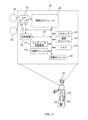
図1は本開示の態様によりオペレーター100がロボット106を制御する例を示す。図1に示されるように、オペレーター100は、ロボット106を制御するための視覚システム102及び動作制御器104(例えばジェスチャ追従システム)を備える。この例では、オペレーター100はロボット106を1つ以上のタスクを実行するために制御してもよい。図1の例では、ロボット106はキッチン108にて訓練される。本開示の態様はロボット106をキッチン108で訓練することに限定されず、その他の環境も考慮されている。
FIG. 1 illustrates an example of an
視覚システム102はオペレーター100の視覚を捕捉するだけでなく、供給ビデオを提供してもよい。オペレーター100はロボット106から離れた位置にいてもよい。本例では、ロボット106はキッチン108に位置し、オペレーター100はロボット制御センター114のようなキッチン108と異なる場所に位置する。
The
視覚システム102はロボット106の供給ビデオを提供してもよい。例えば、視覚システム102はロボット106の前方視点に基づくキッチン108の光景を提供してもよい。360°の風景のようなその他の視点が提供されてもよい。視点はロボット106のビデオカメラのような1つ以上の視覚センサを使用して提供される。視覚システム102は図1に示されるようなヘッドセットに限定されない。視覚システム102はモニタ110、画像プロジェクタ、又はロボット106からの供給ビデオを表示可能なその他の装置であってもよい。
The
ロボット106の一つ以上のアクションが動作制御器104を介して制御されてもよい。例えば、動作制御器104はオペレーター100のジェスチャを捉え、捉えたジェスチャをロボット106が真似してもよい。オペレーター100はロボット106の運動、手足の動作、及びその他のアクションを、動作制御器104を介して制御してもよい。本開示の態様は動作制御器104を介してオペレーター100のジェスチャを捉えることに限定されない。その他の型のジェスチャ捕捉システムも考えられる。オペレーター100は無線接続112を介してロボット106を制御してもよい。加えて、ロボット106は無線接続112を介してオペレーター100へ供給ビデオのようなフィードバックを提供してもよい。
One or more actions of the
ロボット106は特定の環境(例えばキッチン108)及び/又は類似した環境を走行するよう訓練されていてもよい。加えて、ロボット106は特定の環境中の物体、及び/又は任意の環境中の類似した物体に対してタスクを実行するように訓練されていてもよい。例えば、ロボット106はキッチン108内の引き出しを開け閉めするよう訓練されていてもよい。訓練はキッチン108内の引き出しに対してのみ、及び/又は別のキッチンの引き出しなどの、任意の環境内の類似した引き出しに対して実装されていてもよい。
The
議論したように、テスト時間中に訓練をアップデートすること(例えば実世界環境)が理想的である。本開示の態様はロボットのためにニューラルネットワークにより決定された経路を表示して編集するためのユーザーインターフェースを提供することに関する。ある構成では、ロボットは意図する経路を提供し、ユーザーはピクセルを運転可能又は運転不可能としてマークして意図する経路を更新してもよい。 As discussed, updating training during test time (e.g., real-world environment) is ideal. Aspects of the present disclosure relate to providing a user interface for displaying and editing a path determined by a neural network for a robot. In one configuration, the robot provides an intended path, and a user may update the intended path by marking pixels as drivable or undrivable.
訓練中、オペレーターはロボットを環境中で走行させてもよい。加えて、又は代わりに、ロボットは訓練中に自動的に環境中を走行してもよい。ロボットは走行した経路をメモリに記憶する。記憶された走行経路は、運転可能な経路と関係する画像中のピクセルと運転不可能な経路と対応する画像中のピクセルとを判断するよう、ネットワークを訓練するために使用される。新しい環境又は訓練に使用された環境と同じ環境で運転可能な経路を判断するように訓練されるロボット。 During training, an operator may navigate the robot through the environment. Additionally or alternatively, the robot may navigate the environment automatically during training. The robot stores the path traveled in memory. The stored path traveled is used to train the network to determine pixels in the image that are associated with drivable paths and pixels in the image that correspond to non-drivable paths. The robot is trained to determine drivable paths in a new environment or in the same environment as that used for training.
運転可能な経路はロボットが走行し得る経路である。ロボットは運転不可能な経路を走行しないことがあり得る。例えば、経路上の物体により、経路が運転不可能なものとなり得る。ある構成では、運転可能な経路を判断するために奥行データが使用される。物体の高さが閾値以上の場合、物体のある経路の一部が運転不可能としてマークされる。 A drivable path is a path that the robot may travel. The robot may not travel on a non-drivable path. For example, an object on the path may make the path non-drivable. In one configuration, depth data is used to determine drivable paths. If the height of the object is above a threshold, the part of the path where the object is located is marked as non-drivable.
図2Aは本開示の態様による環境202中のロボット200の例を示す。明確にするために、図2Aは環境202の上面図である。図2Aに示されるように、環境202はダイニングテーブル204、シンク206、及びカウンター210を含む。この例では、訓練中、ロボット200は環境202中を経路212に沿って走行した。ロボット200は経路212をメモリに記憶し、経路212をロボット200のニューラルネットワークを訓練するために使用する。訓練は、現在の環境202に加えて、現在の環境202と異なる環境で運転可能な経路を判断するために使用される。
2A illustrates an example of a
図2Bは本開示の態様による訓練されたニューラルネットワークに基づいて判断された、ロボット200の意図する経路226の例を示す。ニューラルネットワークは、訓練環境202からの経路212のような1つ以上の過去の経路に基づいて訓練される。図2Bの現在の環境250は図2Aの訓練環境202と異なる。それにも関わらずロボット200は、訓練中又は訓練後に訓練環境202中の意図する経路を決定してもよい。
FIG. 2B illustrates an example of an intended
図2Bの例はロボット200の視点に基づいている。図2Bの画像は遠隔のオペレーターへ出力され、遠隔地にある表示装置へ表示されてもよい。図2Bに示すように、意図する経路226ではテーブル220の周りを走行する。意図する経路226に加えて、ニューラルネットワークは運転可能領域228を判断する。意図する経路226は運転可能領域228の境界内にある。ある構成では、運転可能領域228は意図する経路226に重なる。画像中のピクセルが運転可能領域228に属すると識別される。
The example of FIG. 2B is based on the perspective of the
図2Bに示されるように、ニューラルネットワークは床の上の物体224(例えば冷蔵庫222のコード)を識別する。訓練、物体224の奥行(例えば高さ)及び/又はその他のファクタに基づき、ニューラルネットワークは物体224の領域は運転不可能であると判断する。かくして運転可能領域228は物体224の領域と交差しない。
As shown in FIG. 2B, the neural network identifies an object 224 (e.g., a code on a refrigerator 222) on the floor. Based on training, the depth (e.g., height) of the
ある構成では、ロボット200の視点がオペレーターへ出力されるとき、オペレーターはニューラルネットワークが運転可能領域228を正しく識別したかどうかを判断する。オペレーターはニューラルネットワークの決断を修正するために運転可能領域228を更新してもよい。更新は、ディスプレイ中の領域を運転可能又は運転不可能としてマークするようなユーザー入力を通して提供されてもよい。
In one configuration, when the robot's 200 viewpoint is output to an operator, the operator determines whether the neural network correctly identified the
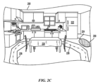
図2Cは本開示の態様によりロボット200の運転可能領域228を更新する例を示す。図2Cに示されるように、人間のオペレーターは環境250の画像を、新しい運転可能領域230をマークすることにより更新する。加えて、又は代わりに、人間のオペレーターは運転可能領域228を運転不可能としてマークしてもよい(図2Cには示されない)。現在の環境における運転可能領域228を編集した後は、ニューラルネットワークは後続の経路を判断する際に人間のオペレーターによる編集を考慮する。
FIG. 2C illustrates an example of updating the
ニューラルネットワークのコアの重みは、新しいユーザーにより提供された編集済の情報によって変わることはない。ある構成では、サポートベクタマシン(SVM)がネットワーク出力の末端に付加される。SVMの重みはユーザーにより編集された情報に基づいて更新される。SVMの重みの更新はリアルタイムで行われてもよい。従って、SVMの更新はネットワーク全体を再訓練するよりも速い。更に、ユーザーインターフェースを使用して新たに教示された運転可能/運転不可能領域の重要性を調整することが可能である。例えば、スライダーによりユーザーが新たな運転可能/運転不可能領域の重みを調整できてもよい。従って、SVMは適切な分類をリアルタイムで行わされ得る。 The core weights of the neural network are not changed by the new user-edited information. In one configuration, a support vector machine (SVM) is added to the end of the network output. The weights of the SVM are updated based on the user-edited information. The SVM weights may be updated in real time. Thus, updating the SVM is faster than retraining the entire network. Furthermore, the user interface can be used to adjust the importance of the newly taught drivable/undrivable regions. For example, a slider may allow the user to adjust the weights of the new drivable/undrivable regions. Thus, the SVM can be made to make the appropriate classification in real time.
議論したように、訓練後、ロボットは1つ以上の訓練されたタスクを実行するために初期化されてもよい。例えば、ロボットは環境中を走行し、そして/又は環境中の物体を操作するようなタスクが課されてもよい。ロボットは命令されたタスクを実行する際に生の画像データを収集する。生の画像データはキーフレームと比較される。 As discussed, after training, the robot may be initialized to perform one or more trained tasks. For example, the robot may be tasked with navigating an environment and/or manipulating objects in the environment. The robot collects raw image data as it performs the commanded task. The raw image data is compared to the keyframes.
一つ以上のキーフレームが現在の画像データと一致する場合は、合致したキーフレームと関連した動作が実行されてもよい。例えば、ロボットは引き出しを開け、又は閉めてもよい。別の例としては、ロボットは蛇口を開けるか、又は閉めてもよい。加えて、又は代わりに、前の動作が完了すると、行動の実行がキューに追加されてもよい。別の例として、ロボットはキーフレームに基づいて現在の位置を判断してもよく、現在の位置から別の位置へ経路を走行するために使用してもよい。ロボットが環境中を移動するか、又は環境中の物体の位置が変更されるに従って、新しいキーフレームが参照されてもよい。 If one or more key frames match the current image data, the action associated with the matching key frames may be executed. For example, the robot may open or close a drawer. As another example, the robot may turn on or turn off a faucet. Additionally or alternatively, an action may be added to a queue for execution upon completion of a previous action. As another example, the robot may determine its current location based on the key frames, which may be used to navigate a path from the current location to another location. As the robot moves through the environment, or as the positions of objects in the environment change, new key frames may be referenced.
ある構成では、ピクセルディスクリプタを比較する前に1つ以上のピクセルがフィルタされる。外れ値をフィルタするために関数が実行されてもよい。例えば、観察されたデータをランダムにサンプルすることでピクセルの外れ値をフィルタするためにrandom sample consensus(RANSAC)関数を使用してもよい。ピクセルをフィルタすることによりノイズが削減され正確性が向上する。 In one configuration, one or more pixels are filtered before comparing the pixel descriptors. A function may be performed to filter outliers. For example, a random sample consensus (RANSAC) function may be used to filter pixel outliers by randomly sampling the observed data. Filtering the pixels reduces noise and improves accuracy.
議論したように、現在の画像の奥行及び/又は角度は一致したキーフレームの奥行及び/又は角度から異なり得る。従って、ある構成では、現在の画像データの一致したピクセルとキーフレームのピクセルとの間の相対変換が判断される。すなわち、現在の画像とキーフレームとの比較に基づいて姿勢デルタが判断され得る。デルタはキーフレームから現在の画像へのロボットの姿勢の変化のことである。 As discussed, the depth and/or angle of the current image may differ from the depth and/or angle of the matched keyframe. Thus, in one configuration, a relative transformation between the matched pixels of the current image data and the pixels of the keyframe may be determined. That is, a pose delta may be determined based on a comparison of the current image and the keyframe. The delta is the change in the pose of the robot from the keyframe to the current image.
姿勢デルタはピクセルディスクリプタの奥行情報に基づいて判断されてもよい。奥行情報はセンサからピクセルに対応する物体への距離である。姿勢デルタは現在の画像とキーフレームとの間の(x,y,z)座標、ロール、ピッチ、及びヨーの変化である。すなわち、姿勢デルタにより、キーフレームから現在の画像へと画像がどのように変化したかがセンサの移動に基づいて説明される。 The pose delta may be determined based on the depth information in the pixel descriptor. The depth information is the distance from the sensor to the object corresponding to the pixel. The pose delta is the change in (x,y,z) coordinates, roll, pitch, and yaw between the current image and the keyframe. That is, the pose delta describes how the image has changed from the keyframe to the current image based on the movement of the sensor.
一致したピクセルの数の増加に関連して姿勢デルタの正確性が増加する。本開示では、一致したピクセルの数は一致した特徴の数よりも大きくなり得る。かくして、本開示の態様は画像を特徴のみに基づいて比較する従来のシステムと比較して姿勢デルタの判断の正確性を向上させる。姿勢デルタを判断するために最小二乗関数を使用してもよい。 The accuracy of the pose delta increases in relation to the increasing number of matched pixels. In the present disclosure, the number of matched pixels may be greater than the number of matched features. Thus, aspects of the present disclosure improve the accuracy of pose delta determination compared to conventional systems that compare images based solely on features. A least squares function may be used to determine the pose delta.
実行される動作のパラメーターの更新に、ピクセルのピクセルディスクリプタの1つ以上の数値の間の姿勢デルタ(例えば相対変換)を使用してもよい。例えば、ロボットがキーフレームにて定義された位置と比較して物体から1フィート(約30.5センチメートル)離れていることを姿勢デルタが示している場合、ロボットの現在の位置(例えば姿勢)を考慮して動作が更新されてもよい。キーフレームにて定義された位置は、タスクを実行するためにロボットを訓練する際に使用する位置である。 A pose delta (e.g., relative transformation) between one or more numerical values of the pixel descriptor of a pixel may be used to update the parameters of the action to be performed. For example, if the pose delta indicates that the robot is one foot (approximately 30.5 centimeters) away from an object compared to a position defined in a keyframe, the action may be updated to take into account the robot's current position (e.g., pose). The position defined in the keyframe is the position to use when training the robot to perform the task.
図3Aは本開示の態様による視覚システムからの出力300の別の例を示す。図3Aに示されるように、出力300は現在の画像302、キーフレーム308、ヒストグラム306、及び姿勢確信度ウインドウ304を含む。出力300はロボットの現在の位置から離れた位置に表示されてもよい。例えば、出力300はロボットの動作を制御する制御センター(例えば図1のロボット制御センター114)に表示されてもよい。
FIG. 3A illustrates another example of
現在の画像302はロボットの現在の視界からの画像である。キーフレーム308は、現在の画像302と比較されるキーフレームのセットからの1つのキーフレームである。ヒストグラム306は現在の画像302からキーフレームのセット中の各キーフレームへの一致に関する確信度スコアを示す。
訓練中には、走行タスクにおいて、ロボットは経路に沿ったスタートからゴールまでの特定の地点にて、キーフレームを撮影する。経路上で撮影されたキーフレームは走行タスクにおいてキーフレームのセットとして使用される。テスト中、ロボットは現在の位置を識別するために現在の画像をキーフレームのセットと比較する。 During training, the robot captures keyframes at specific points along a path in the running task, from the start to the finish. The keyframes captured along the path are used as a set of keyframes in the running task. During testing, the robot compares its current image to the set of keyframes to identify its current location.
一致したピクセル(例えばピクセルディスクリプタ)の数に基づいて、ロボットは現在の画像から特定のキーフレームへの一致の確信度を判断する。一致の確信度が閾値よりも高ければ、ロボットは一致したキーフレームに関連したタスクを実行する。タスクは位置判定(例えばロボットの現在の位置を判断すること)を含んでもよい。図3Aの例にて、ロボットは経路上の、一致の確信度310が最も高いキーフレームの位置に対応する位置にいると判断する。
Based on the number of matching pixels (e.g., pixel descriptors), the robot determines the confidence of a match from the current image to a particular keyframe. If the confidence of the match is higher than a threshold, the robot performs a task associated with the matching keyframe. The task may include location determination (e.g., determining the robot's current location). In the example of FIG. 3A, the robot determines that it is at a location on the path that corresponds to the location of the keyframe with the highest confidence of the
ヒストグラム306はタスクに応じて異なってもよい。図3Aのヒストグラム306は走行タスクのためのものである。ヒストグラム306はロボットが操作(例えば物体の操作)タスクを実行している場合には異なるものとなり得る。操作タスクのためのキーフレームのセットは、走行タスクのためのキーフレームのセットと比較して少ないキーフレームを有していてもよい。
The
例えばキャビネットを開ける場合、ロボットはキャビネットが閉じていたり少し開いていたりする場合に開けるように訓練されていてもよい。この例では、ヒストグラムは、棒グラフ中に2本のキーフレーム一致棒グラフを有し得る。1本の棒グラフは現在の画像が閉じたキャビネットのキーフレームに一致する確信度を示し、もう1本の棒グラフは現在の画像が部分的に開いたキャビネットのキーフレームに一致する確信度を示し得る。 For example, when opening a cabinet, the robot may be trained to open the cabinet when it is closed or partially open. In this example, the histogram may have two keyframe matching bars in the bar graph. One bar may indicate the confidence that the current image matches the keyframe with a closed cabinet, and the other bar may indicate the confidence that the current image matches the keyframe with a partially open cabinet.
姿勢確信度ウインドウ304は姿勢一致器から得た姿勢一致の確信度を示す。ある構成では、姿勢デルタを判断する前に、ロボットは数々の基準が1つ以上の閾値を満足するかどうかを判断する。基準は奥行、姿勢、クリーク、エラー、及びその他の要素に基づいていてもよい。
The
ある構成では、ロボットは奥行値を有するピクセルの数を判断する。ガラス又は艶のある面のような面では、ロボットは奥行を判断できないことがある。したがって、これらの面に対応するピクセルは奥行値を有さない場合がある。奥行値を有するピクセルの数はピクセルをフィルタする前に判断されてもよい。奥行値を有するピクセルの数が閾値よりも大きければ、奥行の基準は満足される。姿勢確信度ウインドウ304は、奥行値を有するピクセルの数の棒グラフ320と閾値を示す棒グラフ322とを比較する棒グラフを含んでいてもよい。棒グラフは色分けされていてもよい。
In one configuration, the robot determines the number of pixels that have depth values. On surfaces such as glass or shiny surfaces, the robot may not be able to determine depth. Thus, pixels corresponding to these surfaces may not have depth values. The number of pixels that have depth values may be determined before filtering the pixels. If the number of pixels that have depth values is greater than a threshold, the depth criterion is met. The
加えて、又は代わりに、姿勢確信度ウインドウ304の棒グラフは現在の画像とキーフレームの間で揃う特徴の数の棒グラフとアライメント閾値の棒グラフとの比較を含んでもよい。キーフレームと現在の画像の一致の正確性を判断するために、ロボットは姿勢変換を適用し、現在の画像における物体の特徴がキーフレーム中の物体の特徴と幾つ揃うか、及びその反対を判断してもよい。もしも特徴が静的でない物体と紐づけられていた場合、特徴は揃わなくてもよい。例えば、キーフレームは現在の画像には既に存在しないカップを含み得る。従って、カップの特徴は画像間で揃わなくなり得る。揃った特徴の数はクリークインライアと呼ばれてもよい。クリークインライアが閾値よりも大きい場合に姿勢デルタが生成され得る。
Additionally or alternatively, the bar graph in the
加えて、又は代わりに、姿勢確信度ウインドウ304の棒グラフは姿勢を判断するために使用される特徴の数の棒グラフと姿勢閾値の棒グラフの比較を含んでもよい。すなわち、姿勢を判断するために一定数の特徴が使用されるべきである。姿勢を判断するために使用される特徴の数が姿勢閾値よりも小さい場合は、姿勢デルタは計算されなくてもよい。姿勢を判断するために使用される特徴の数は姿勢インライアと呼ばれてもよい。
Additionally or alternatively, the bar graph in the
姿勢確信度ウインドウ304の棒グラフは姿勢デルタの二乗平均平方根(RMS)エラーの棒グラフと閾値の比較をも含み得る。RMSエラーがRMSエラー閾値よりも小さければ、姿勢デルタは申し分がないものであり得る。RMSエラーがRMSエラー閾値よりも大きければ、ユーザー又はロボットはタスクを実行するために姿勢デルタを使用しなくてもよい。
The bar graph in the
姿勢確信度ウインドウ304は棒グラフに限定されず、他のグラフ又は画像が使用されてもよい。姿勢確信度ウインドウ304の基準は議論された基準に限定されず、他の基準が用いられてもよい。
The
図3Bは本開示の態様による視覚システムからの出力350の、更に別の例を示す。図3Bに示されるように、出力350は現在の画像352、キーフレーム358、ヒストグラム354、及び姿勢確信度ウインドウ356を含む。出力350はロボットの現在の位置から離れた位置に表示されてもよい。
FIG. 3B illustrates yet another example of
姿勢確信度ウインドウ356は一致経路に渡る特徴の数及びRMSエラーを可視化する。各特徴(例えば基準)に対して、現在の値が閾値と比較される。例えば、奥行に関して、現在の奥行(389)が閾値(65)と比較される。
各棒グラフの棒は現在の値と閾値に関する。
The
Each bar in the bar graph relates to a current value and a threshold value.
ヒストグラム354は現在の画像と一致が行われる各キーフレームの一致スコアを可視化する。閾値よりも高く最も高い一致スコアを有するキーフレームが一致するキーフレームとして選択され得る。一致したキーフレームは出力350の中にキーフレーム358として表示されてもよい。
The
議論したように、本開示の態様は、仮想現実内の人間からタスクをデモンストレーションにより教示された後に、実世界環境にて自律的に人間のレベルのタスクを実行することが可能な移動操作ハードウエア及びソフトウエアシステムに関する。ある構成では、移動操作ロボットが使用される。ロボットは全身タスク空間ハイブリッド位置/力制御を含んでもよい。加えて、議論したように、ロバストに学習された風景の密な視覚的エンベディング表現にリンクされた、パラメーター化されたプリミティブがロボットに教示される。最後に、教示された動作のタスクグラフが生成されてもよい。 As discussed, aspects of the present disclosure relate to mobile manipulation hardware and software systems capable of autonomously performing human-level tasks in a real-world environment after being taught the tasks by demonstration from a human in virtual reality. In one configuration, a mobile manipulation robot is used. The robot may include whole-body task-space hybrid position/force control. Additionally, as discussed, the robot is taught parameterized primitives linked to a robustly learned dense visual embedding representation of the scene. Finally, a task graph of the taught actions may be generated.
固定された物体のセットを認識したり予め定義されたタスクを実行したりするようにロボットにプログラミングや訓練を行うよりも、本開示の態様によりロボットは新しい物体やタスクを人間によるデモンストレーションから学習することができる。学習されたタスクは自然に変化する条件下でロボットにより自律的に実行されてもよい。ロボットは以前の物体モデル又はマップを使用せず、1つの例から、与えられた動作のセットを任意の風景及び物体へ関連付けるよう教示されることができる。視覚システムは既存の教師付き及び教師なしデータセットを使用してオフラインで訓練されてもよく、システムの残りは追加の訓練データなしに機能してもよい。 Rather than programming and training a robot to recognize a fixed set of objects or perform predefined tasks, aspects of the present disclosure allow the robot to learn new objects and tasks from human demonstrations. The learned tasks may be performed autonomously by the robot under naturally changing conditions. The robot can be taught to associate a given set of actions to any scene and object from a single example, without using previous object models or maps. The vision system may be trained offline using existing supervised and unsupervised datasets, and the rest of the system may function without additional training data.
タスク空間の動作を直接教示する従来のシステムとは対照的に、本開示の態様はパラメーター化された動作のセットを教示する。これらの動作は、教示されたパラメーターを最小化し、実行中のロバスト性を提供するために、衝突のない動作計画とエンドエフェクタのハイブリッド(位置及び力)デカルト制御を組み合わせる。 In contrast to conventional systems that directly teach task-space movements, aspects of the present disclosure teach a set of parameterized movements that combine collision-free motion planning and hybrid (position and force) Cartesian control of the end effector to minimize the taught parameters and provide robustness during execution.
ある構成では、タスクに特化した、訓練された密な視覚に関するエンベディングが計算される。このピクセルに関するエンベディングはパラメーター化された動作を風景にリンクさせる。リンクにより、システムは、新しい状況への一般化と引き換えにロバスト性の高い様々な環境を取り扱い得る。 In one configuration, a task-specific dense embedding is computed over the trained vision. This pixel-wise embedding links the parameterized motion to the scene. This link allows the system to handle a variety of environments with greater robustness at the expense of generalizing to new situations.
タスクの動作は、視覚的な入力条件と、成功に基づく終了条件を用いて独立に教示されてもよい。動作は動的タスクグラフ内にて互いに連結されてもよい。動作が連結されているため、ロボットはタスクシーケンスを実行するために行動を再利用してもよい。 Task actions may be taught independently using visual input conditions and success-based exit conditions. Actions may be linked together in a dynamic task graph. Because actions are linked, the robot may reuse actions to execute a task sequence.
ロボットは多自由度(DOF)であってもよい。例えば、ロボットは車台、胴体、左腕、右腕、及び頭の5つのサブシステムに分けられた31自由度(DOF)であってもよい。ある構成では、車台は、「疑似ホロノミック」な可動性を実現する4つの駆操舵可能な動輪(例えば計8自由度)を含む。駆動/操舵アクチュエータパッケージは様々なモーター及びギアヘッドを含んでもよい。胴体は5自由度(ヨー、ピッチ、ピッチ、ピッチ、ヨー)であってもよい。それぞれの腕は7自由度であってもよい。頭はパン/チルトの2自由度であってもよい。それぞれの腕は劣駆動の指を有する1自由度のグリッパを含んでもよい。本開示の態様は上に議論したロボットに限定されない。その他の構成が考えられる。一例では、ロボットはスポンジ又はモップのようなカスタムツールを含んでもよい。 The robot may have multiple degrees of freedom (DOF). For example, the robot may have 31 degrees of freedom (DOF) divided into five subsystems: chassis, torso, left arm, right arm, and head. In one configuration, the chassis includes four steerable wheels (e.g., 8 DOF total) that provide "quasi-holonomic" mobility. The drive/steering actuator package may include various motors and gear heads. The torso may have 5 DOF (yaw, pitch, pitch, pitch, yaw). Each arm may have 7 DOF. The head may have 2 DOF, pan/tilt. Each arm may include a 1 DOF gripper with underactuated fingers. Aspects of the present disclosure are not limited to the robots discussed above. Other configurations are contemplated. In one example, the robot may include a custom tool such as a sponge or mop.
ある構成では、ロボットには環境との相互作用力を計測するための力/トルクセンサが一体化されている。例えば、力/トルクセンサはそれぞれの腕の手首に配されていてもよい。頭には、広い視野を提供し、人間やロボットがタスクを実行するためのVRコンテキストを提供するための知覚センサが統合されていてもよい。 In one configuration, the robot is integrated with force/torque sensors to measure interaction forces with the environment. For example, force/torque sensors may be located at the wrists of each arm. The head may be integrated with perception sensors to provide a wide field of view and provide a VR context for the human or robot to perform a task.
本開示の態様はロボット制御のための数段階の抽象化を提供する。ある構成では、最も低い制御レベルにより、ロボットの全ての自由度のリアルタイムな協調制御が提供される。リアルタイム制御は関節制御及び部品の制御を含み得る。関節制御により、低レベルの装置通信が実装され、装置のコマンドや状態を一般的な形で公開する。加えて、関節制御はアクチュエータ、力センサ、及び慣性計測装置をサポートする。関節制御は異なるロボットをサポートするためにランタイムにて構成されていてもよい。 Aspects of the present disclosure provide several levels of abstraction for robot control. In one configuration, the lowest control level provides real-time coordinated control of all degrees of freedom of the robot. Real-time control may include joint control and part control. Joint control implements low-level device communication and exposes device commands and states in a generic way. In addition, joint control supports actuators, force sensors, and inertial measurement units. Joint control may be configured at run-time to support different robots.
部品制御により、ロボットを部品(例えば右腕、頭等)に分け、各部品に対してパラメーター化された制御器のセットを提供することで、ロボットのより高レベルの協働作用を扱い得る。部品制御により、関節位置及び速度、関節アドミッタンス、カメラ目視、車台位置及び速度、並びにハイブリッドタスク空間における姿勢、速度、及びアドミッタンス制御の制御器が提供されてもよい。 Part control can handle higher level collaboration of the robot by breaking the robot into parts (e.g. right arm, head, etc.) and providing a set of parameterized controllers for each part. Part control may provide controllers for joint position and velocity, joint admittance, camera vision, chassis position and velocity, as well as pose, velocity, and admittance control in a hybrid task space.
エンドエフェクタのタスク空間制御により、ロボット制御を別次元で抽象化することが可能になる。このレベルの抽象化により、所望の動作を達成するためのロボットの姿勢の問題が解決される。ハイブリッドデカルト制御のための全身の逆運動学(IK)が二次のプログラムとして形成され、解かれる。部品には関節位置、速度、加速度、及び重力トルクに関して線形拘束が存在し得る。 Task-space control of the end effector allows another level of abstraction in robot control. This level of abstraction solves the problem of posing the robot to achieve the desired motion. The inverse kinematics (IK) of the whole body for hybrid Cartesian control is formulated and solved as a second-order program. Parts may have linear constraints on joint positions, velocities, accelerations, and gravitational torques.
全身のIKはデカルト座標における姿勢のゴールに到達するための動作計画に使用されてもよい。ある構成では、環境の占有されたボクセルは球体やカプセル型が当てはめられる。ロボットと世界の衝突を避けるために、ボクセルの衝突拘束がIKの二次プログラムに加えられる。IKの二次プログラムにて、ノード間の操舵関数としてデカルト空間におけるサンプリングを行い、rapidly-exploring random tree(RRT)を用いて動作計画が行われてもよい。 Whole-body IK may be used for motion planning to reach a goal pose in Cartesian coordinates. In one configuration, occupied voxels of the environment are fitted with spheres or capsule shapes. Voxel collision constraints are added to the quadratic IK program to avoid collisions between the robot and the world. Motion planning may be done using a rapidly-exploring random tree (RRT) in the quadratic IK program, sampling in Cartesian space as a steering function between nodes.
デカルト空間における計画により、自然で直接的な動作になる。操舵機能としてIKの二次プログラムを使用することにより、計画の信頼性を向上させることができ、計画と実行に同じ制御器を、両者の食い違いを削減するために用いてもよい。同様に、関節位置のゴールに向けた動作計画と、操舵機能として働く部品制御による関節位置制御器とを組み合わせてRRTを使用する。 Planning in Cartesian space results in natural and straightforward motion. Using a quadratic IK program as the steering function can improve planning reliability, and the same controller may be used for planning and execution to reduce discrepancies between the two. Similarly, RRT is used in combination with motion planning towards joint position goals and a part-controlled joint position controller acting as the steering function.
次の抽象化レベルによりパラメーター化された動作が定義される。ある構成では、パラメーター化された動作は、パラメーター化可能で、組み合わせることでタスクを成し遂げることが可能な、プリミティブなアクションである。動作は、握る、持ち上げる、置く、引く、ひっこめる、拭く、直接制御、のような操作アクション、関節を動かす、速度命令により運転する、位置命令により運転する、能動的な障害物回避を行いながらの経路追従、のような走行アクション、及び目視して停止するといった予備的アクションを限定せず含んでもよい。 The next level of abstraction defines parameterized behaviors. In one configuration, parameterized behaviors are primitive actions that can be parameterized and combined to accomplish a task. Behaviors may include, but are not limited to, manipulation actions such as grab, lift, place, pull, retract, wipe, and direct control; navigation actions such as moving joints, driving by velocity command, driving by position command, path following with active obstacle avoidance, and preparatory actions such as look and stop.
各動作は、ロボットの部品の一つ以上の関節又はデカルト座標における動作のような、単一又は複数の異なる型のアクションを有することができる。各アクションは位置、速度、又はアドミッタンス制御のような異なる制御手法を使用することができ、外部の障害物を回避するために動作計画を使用することを選択することができる。動作計画を使用するかに関わらないロボットの動作は、自己衝突を回避し、動作制御拘束を満たす。 Each motion can have one or more different types of actions, such as motions at one or more joints or Cartesian coordinates of the robot's parts. Each action can use a different control strategy, such as position, velocity, or admittance control, and can choose to use motion planning to avoid external obstacles. The motion of the robot, whether or not it uses motion planning, avoids self-collisions and satisfies motion control constraints.
各動作は異なるアクションによりパラメーター化され、その代わりにアクションは独自のパラメーターを有してもよい。例えば、把持動作はグリッパ角度、6Dアプローチ、把持、及びグリッパの(随意的な)持ち上げ時の姿勢の4つのパラメーターから成り立っていてもよい。本例では、これらのパラメーターにより、次の予め定義されたアクションのシーケンスが定義される。(1)所望のグリッパ角度までグリッパを開く(2)6Dアプローチ姿勢までの衝突のない経路を計画し実行する(3)6D把持姿勢までグリッパを動かし接触したら停止する(4)グリッパを閉じる(5)6D持ち上げポーズまでグリッパを動かす。 Each operation may be parameterized with different actions, which in turn may have their own parameters. For example, a gripping operation may consist of four parameters: gripper angle, 6D approach, grip, and (optionally) gripper lift pose. In this example, these parameters define a predefined sequence of actions: (1) open the gripper to the desired gripper angle, (2) plan and execute a collision-free path to the 6D approach pose, (3) move the gripper to the 6D gripping pose and stop on contact, (4) close the gripper, and (5) move the gripper to the 6D lift pose.
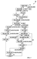
最終レベルの制御の抽象化がタスクである。ある構成では、タスクは、ロボットが操作を行い人間の環境を走行することを可能にする動作のシーケンスとして定義される。タスクグラフ(図5参照)は、異なるタスクをノードとし、異なる移動状況をエッジとし、異常検出及び異常からの回復を含む、有効であり、周期的又は非周期的なグラフである。エッジ状況は異なる物体や環境を取り扱うための各動作の実行状況、力/トルクセンサを使用した手中の物体の検査、音声コマンド、及びキーフレームとの一致を含む。 The final level of control abstraction is the task. In one construction, a task is defined as a sequence of actions that allows the robot to manipulate and navigate the human environment. A task graph (see Figure 5) is a valid, cyclic or acyclic graph with different tasks as nodes and different movement situations as edges, including anomaly detection and recovery. Edge situations include execution of each action to handle different objects and environments, inspection of an object in the hand using force/torque sensors, voice commands, and matching keyframes.
本開示の態様により、ロボットが周囲の環境を理解するための知覚パイプラインが設計される。知覚パイプラインによりロボットはまた、教示されたタスクを踏まえてどのアクションを取るべきかを認識する能力が得られる。ある構成では、一つの視界画像(例えばワイドな視界の左画像)に高解像度カラーステレオペアの複数の奥行画像を投影することにより、融合RGB-D画像が作成される。システムは様々なピクセルレベルの分類及び特徴ベクトル(例えばエンベディング)を提供するためにディープニューラルネットワークのセットを実行する。教示されたシーケンスから呼び出された視覚的特徴に基づき、ピクセルレベルの分類及び特徴ベクトルは一時的な3Dボクセル表現へと累積される。
ピクセルレベルの分類及び特徴ベクトルは実行するべきアクションを呼び出すために使用されてもよい。
According to aspects of the present disclosure, a perception pipeline is designed for a robot to understand its surrounding environment. The perception pipeline also gives the robot the ability to recognize which action to take given the taught task. In one configuration, a fused RGB-D image is created by projecting multiple depth images of a high-resolution color stereo pair onto one field of view image (e.g., wide field of view left image). The system runs a set of deep neural networks to provide various pixel-level classifications and feature vectors (e.g., embeddings). Based on visual features retrieved from the taught sequence, the pixel-level classifications and feature vectors are accumulated into a temporary 3D voxel representation.
The pixel-level classification and feature vectors may be used to invoke actions to be performed.
ある構成では、物体のカテゴリは定義されない。加えて、若しくは物体のモデル又は環境は想定されない。物体を明示的に検出してセグメント分けし、また明示的に6自由度の姿勢を推定するよりも、多用なタスクのために密なピクセルレベルのエンベディングを生成してもよい。教示されたシーケンスからの参照エンベディングが動作分類又は姿勢推定を行うために使用されてもよい。 In some configurations, no object categories are defined, nor are any models of objects or environments assumed. Rather than explicitly detect and segment objects and explicitly estimate 6-DOF poses, dense pixel-level embeddings may be generated for a variety of tasks. Reference embeddings from taught sequences may be used to perform motion classification or pose estimation.
訓練されたモデルは完全な畳み込み型であってもよい。ある構成では、入力画像のピクセルはエンベディング空間の中のある点へそれぞれマップされる。エンベディング空間はモデルの出力により定義される損失関数と訓練手順によって暗黙のうちに定義されるメトリックを与えられる。訓練されたモデルは様々なタスクに使用されてもよい。 The trained model may be fully convolutional. In one configuration, pixels of the input image are each mapped to a point in an embedding space. The embedding space is given a loss function defined by the output of the model and a metric implicitly defined by the training procedure. The trained model may be used for a variety of tasks.
ある構成では、1つの注釈が付された例が与えられれば、訓練されたモデルはセマンティイッククラス中の全てのオブジェクトを検出する。セマンティッククラス中の物体は注釈中のエンベディングとその他の領域中のエンベディングを比較することにより検出されてもよい。モデルは識別損失関数(discriminative loss function)により訓練されてもよい。 In one configuration, given an annotated example, the trained model detects all objects in a semantic class. Objects in a semantic class may be detected by comparing embeddings in the annotation with embeddings in other regions. The model may be trained with a discriminative loss function.
モデルはオブジェクトインスタンスを判断するために訓練されてもよい。このモデルは独立したオブジェクトを識別し、そして/又は数える。モデルは各ピクセルのベクトル(2Dエンベディング)を予測するために訓練されてもよい。ベクトルはそのピクセルを含むオブジェクトの重心を指し示してもよい。ランタイムにおいて、同じ重心を指すピクセルはその風景のセグメントとしてグループ分けされてもよい。ランタイムにおける実行は3Dで行われてもよい。 The model may be trained to determine object instances. The model identifies and/or counts individual objects. The model may be trained to predict a vector (a 2D embedding) for each pixel. The vector may point to the centroid of the object that contains that pixel. At runtime, pixels that point to the same centroid may be grouped as a segment of the scene. The runtime execution may be in 3D.
モデルは3Dの対応関係について訓練されてもよい。このモデルは風景内の任意の3D地点のビューが同じエンベディングに対してマッピングされるように、ビューや照明に対して不変なエンベディングをピクセルごとに提供する。このモデルは損失関数を使用して訓練されてもよい。 A model may be trained on 3D correspondences. The model provides a per-pixel embedding that is invariant to view and lighting, such that any view of a 3D point in the scene is mapped to the same embedding. The model may be trained using a loss function.
各RGB-Dフレームに対するピクセルに関するエンベディング(及び奥行データ)は動的3Dボクセルマップへと融合される。各ボクセルは第1及び第2の順序の位置、色、エンベディングの統計を累積する。動的オブジェクトの有効期限はボクセルの奥行画像への逆投影に基づく。ボクセルマップは、セマンティック及びインスタンスレーベル、並びに幾何学的近似性に基づいて、標準的なグラフセグメンテーションを使用して分割される。ボクセルマップは標高及び走行可能性の分類統計を有する2.5Dマップへと次元が削減される。 Pixel-wise embeddings (and depth data) for each RGB-D frame are fused into a dynamic 3D voxel map. Each voxel accumulates first and second order location, color and embedding statistics. Dynamic object lifetimes are based on the backprojection of the voxel into the depth image. The voxel map is partitioned using standard graph segmentation based on semantic and instance labels, and geometric proximity. The voxel map is dimensionally reduced to a 2.5D map with classification statistics for elevation and drivability.
2.5Dマップは衝突のない車台の動作に使用される一方、ボクセルマップは衝突のない全身の動作計画に使用される。3Dにおける衝突の検査のために、貪欲法を使用してマップ中のボクセルがカプセルへとグループ化されてもよい。セグメント化されたオブジェクトは、物体が把持された際に手に付属させるための動作に使用されてもよい。 The 2.5D map is used for collision-free chassis motion, while the voxel map is used for collision-free whole-body motion planning. For collision checking in 3D, voxels in the map may be grouped into capsules using a greedy method. The segmented object may be used for motion to attach to the hand when the object is grasped.
ロボットは過去に教示されたタスクにて記録された特徴に高度に関連する風景中の(又は特定の操作オブジェクトの)特徴を認識するように、ワンショット学習アプローチにより訓練されてもよい。タスクがユーザーによって実演されると、特徴がタスク全体にわたってキーフレームの形態で保存される。キーフレームは多次元エンベディング及びピクセルごとの奥行(有効であれば)を有するRGB画像であってもよい。 The robot may be trained by a one-shot learning approach to recognize features in the scene (or of a particular manipulated object) that are highly related to features recorded in previously taught tasks. As the task is performed by the user, the features are stored in the form of keyframes across the task. The keyframes may be RGB images with multidimensional embedding and per-pixel depth (if available).
エンベディングは、現在の画像が教示時に存在した参照画像と充分類似しているという想定の下でランタイムにおけるピクセルごとの対応関係を確立し得る特徴ディスクリプタとして機能する。奥行が(ほとんど)全てのピクセルに存在するため、現在の画像と参照画像の姿勢のデルタを解くために対応関係を使用することができる。ユークリッド制約を使用してインライアが検出されてもよく、6自由度の姿勢を解くためにRANSACと共にレーベンバーグ・マルカート最小二乗関数を適用する。 The embeddings act as feature descriptors that can establish pixel-by-pixel correspondences at run-time under the assumption that the current image is sufficiently similar to the reference images present at training time. Since depth is present at (almost) every pixel, the correspondences can be used to solve for the pose delta between the current and reference images. Inliers may be detected using Euclidean constraints, and a Levenberg-Marquardt least-squares function is applied along with RANSAC to solve for the pose in 6 degrees of freedom.
姿勢のデルタは、教示された動作のシーケンスを現在の風景へ適合させるために適用可能な補正の役割を果たす。エンベディングが各ピクセルに対して定義されてもよいことから、キーフレームは画像中の全てのピクセルを含む程広くても良く、又はユーザーが定義したマスク内のピクセルのみを使用する程狭くてもよい。議論したように、ユーザーは、画像中の領域をタスクと関連するものとして、又は物体上にあるものとして選択的に注釈を付することにより、マスクを定義してもよい。 The pose deltas serve as corrections that can be applied to adapt the taught motion sequence to the current scene. Since embeddings may be defined for each pixel, keyframes may be broad enough to include all pixels in the image, or narrow enough to use only pixels within a user-defined mask. As discussed, the user may define the mask by selectively annotating regions in the image as being relevant to the task or on the object.
視覚センシングに加えて、ある構成では、ロボットは音声入力を収集して処理する。音声は、ロボットを教示するための入力として、別のエンベディングのセットを提供する。例として、ロボットは質問を行い、人間からの応答の音声言語を理解することにより音声入力を得る。音声による応答はカスタムのキーワード検出モジュールを使用して理解されてもよい。 In addition to visual sensing, in one configuration the robot collects and processes audio input. Audio provides another set of embeddings as input for teaching the robot. As an example, the robot gets audio input by asking a question and understanding the spoken language of the response from the human. The audio response may be understood using a custom keyword detection module.
ロボットは、完全畳み込みキーワードスポッティングモデルを利用して、カスタムのウェイクワード、物体のセット(例えば「マグ」又は「瓶」)、及び場所のセット(例えば「キャビネット」又は「冷蔵庫」)を理解してもよい。ある構成では、モデルは、例えば32msのようなある間隔でウェイクワードを聞いている。ウェイクワードが検出されたら、ロボットは物体又は場所のキーワードが検出されるかを注意する。訓練の間は、認識をよりロバストにするために人工的にノイズが加えられる。 The robot may utilize a fully convolutional keyword spotting model to understand a custom wake word, a set of objects (e.g., "mug" or "jar"), and a set of locations (e.g., "cabinet" or "fridge"). In one configuration, the model listens for a wake word at some interval, e.g., 32 ms. Once the wake word is detected, the robot notes whether any object or location keywords are detected. During training, artificial noise is added to make the recognition more robust.
議論したように、ロボットにタスクを教示するためには、オペレーターはVRモードのセットを使用する。各動作は、その動作に特有のパラメーターを設定し命令するために、対応するVRモードを有してもよい。各動作モードは、各パラメーターの設定を支援するために、パラメーターの型に応じて、カスタマイズされた視覚化を含んでもよい。例えば、ドアを引く動きのパラメーターを設定する場合、蝶番の軸がラベルされ、線として視覚化され、グリッパを引くための姿勢候補は蝶番を中心とする円弧上に制限される。教示プロセスを支援するために、動作の復元、関連物体による環境への注釈付け、仮想ロボットの再位置決め、カメラ画像、及びVR世界のメニューのような幾つかのユーティリティVRモードが使用される。 As discussed, to teach a task to the robot, the operator uses a set of VR modes. Each action may have a corresponding VR mode to set and command parameters specific to that action. Each action mode may include customized visualizations depending on the type of parameter to aid in setting each parameter. For example, when setting parameters for a door-pulling action, the hinge axis is labeled and visualized as a line, and possible poses for pulling the gripper are restricted to an arc centered on the hinge. To aid in the teaching process, several utility VR modes are used, such as action reconstruction, annotating the environment with relevant objects, repositioning the virtual robot, camera images, and a menu of the VR world.
実行中、ロボットの姿勢及び環境中の部品は訓練中に使用されたものと異なってもよい。教示されたものと類似した環境中の特徴を発見するために特徴一致が使用されてもよい。姿勢デルタは一致した特徴の対応関係から確立されてもよい。ユーザーにより教示された動作が計算された姿勢デルタにより変化してもよい。ある構成では、複数のキーフレームがマッチング問題へ渡される。対応関係の数に基づいて、最も良く一致したキーフレームが選択される。 During execution, the robot's pose and parts in the environment may differ from those used during training. Feature matching may be used to find features in the environment that are similar to those taught. A pose delta may be established from the matched feature correspondences. The motion taught by the user may be altered by the calculated pose delta. In one configuration, multiple keyframes are submitted to the matching problem. Based on the number of correspondences, the best matching keyframe is selected.
図4は本開示の態様によるロボットシステム400のハードウエア実装の例を示す図である。ロボットシステム400は車両、ロボット装置428、又はその他の装置のような、自律又は半自律システムの構成要素であってもよい。図4の例では、ロボットシステム400はロボット装置428の構成要素である。ロボットシステム400は、ロボット装置428のオペレーターの意図を推察することによってロボット装置428のアクションを制御するために使用されてもよい。
FIG. 4 illustrates an example hardware implementation of a
ロボットシステム400はバス430として概ね表されるバスアーキテクチャにより実装されてもよい。バス430はロボットシステム400の特定の用途及び全体的な設計制約に応じて任意の数の相互接続バス及びブリッジを含んでもよい。バス430は、プロセッサ420として表される1つ以上のプロセッサ及び/又はハードウエアモジュール、通信モジュール422、位置モジュール418、センサモジュール402、移動モジュール426、メモリ424、視覚化モジュール408、及びコンピュータ可読媒体414のような様々な回路を接続する。バス430はタイミングソース、周辺機器、電圧制御器、電源管理回路のような、当業者に既知であり、故にこれ以上の説明は行わないその他の様々な回路も接続してもよい。
The
ロボットシステム400は、プロセッサ420に接続された送受信機416、センサモジュール402、視覚化モジュール408、通信モジュール422、位置モジュール418、移動モジュール426、メモリ424、及びコンピュータ可読媒体414を含む。送受信機416はアンテナ434に接続されている。送受信機416は様々な装置と伝送媒体を介して通信する。例えば、送受信機416は通信を介してロボット装置428のオペレーターからの命令を受信してもよい。本明細書中に議論するように、オペレーターはロボット装置428から離れた位置にいてもよい。別の例として、送受信機416はキーフレームマッチングに関する情報を視覚化モジュール408からオペレーターへ送信してもよい。
The
ロボットシステム400はコンピュータ可読媒体414に接続されたプロセッサ420を含む。プロセッサ420は、コンピュータ可読媒体414に記憶され、本開示による機能を提供するソフトウエアの実行を含む処理を行う。ソフトウエアは、プロセッサ420により実行された時、ロボットシステム400により、ロボット装置428又はモジュール402、408、414、416、418、420、422、424、426のような特定の装置に対して説明された様々な機能を実行させる。コンピュータ可読媒体414は、ソフトウエアを実行した時にプロセッサ420により操作されるデータを記憶するためにも使用されてもよい。
The
センサモジュール402は、第1のセンサ406及び第2のセンサ404のような異なるセンサを介して測定値を得るために使用されてもよい。第1のセンサ406は、2D画像を撮影するためのステレオカメラ又はRGBカメラのような視覚センサであってもよい。第2のセンサ404はLiDARセンサ、RADARセンサ、又はRGB-Dセンサのような測距センサであってもよい。当然、本開示の態様は上記のセンサに限られず、例えば、温度、音波、及び/又はレーザー等のその他の型のセンサもまたセンサ404、406のどちらかとして考えられる。第1のセンサ406及び第2のセンサ404による測定値は、本明細書中に説明した機能を実装するために、コンピュータ可読媒体414と併せて、プロセッサ420、センサモジュール402、通信モジュール422、位置モジュール418、移動モジュール426、メモリ424、のうち1つ以上により処理されてもよい。ある構成では、第1のセンサ406及び第2のセンサ404により捕捉されたデータは送受信機416を介して供給ビデオとしてオペレーターへ送信されてもよい。第1のセンサ406及び第2のセンサ404はロボット装置428へ接続されていてもよく、又はロボット装置428と通信状態にあってもよい。
The
位置モジュール418はロボット装置428の位置を判断するために使用されてもよい。例えば、位置モジュール418は、ロボット装置428の位置を判断するために、全地球測位システム(GPS)を使用してもよい。通信モジュール422は送受信機416を介した通信を促進するために使用されてもよい。例えば、通信モジュール422は、WiFi、long term evolution(LTE)、3G等のような異なる無線プロトコルを介した通信能力を提供してもよい。通信モジュール422はまた、ロボットシステム400のモジュールではない、ロボット装置428のその他の構成要素と通信するために使用されてもよい。
The
移動モジュール426は、ロボット装置428の、及び/又はロボット装置428の構成要素(例えば手足、手、等)の移動を促進するために使用されてもよい。例えば、移動モジュール426は手足438及び/又は車輪432の動きを制御してもよい。別の例として、移動モジュール426はエンジン又はバッテリーのようなロボット装置428の電力源と通信中であってもよい。\
The
ロボットシステム400はまた、ロボット装置428及び視覚化モジュール408の操作に関連するデータを記憶するためのメモリ424を含む。モジュールはプロセッサ420内で実行されるソフトウエアモジュール、コンピュータ可読媒体414及び/又はメモリ424に常駐/記憶されるもの、プロセッサ420に接続された1つ以上のハードウエアモジュール、又はそれらの組み合わせであってもよい。
The
視覚化モジュール408はセンサモジュール402、送受信機416、プロセッサ420、通信モジュール422、位置モジュール418、移動モジュール426、メモリ424、及びコンピュータ可読媒体414と通信可能であってもよい。ある構成では、視覚化モジュール408はロボット装置が意図する経路を環境中に生成する。意図する経路はロボット操作センターのような遠隔地へ送信されてもよい。遠隔地にて意図する経路に対応する視覚化を表示してもよい。
The
視覚化モジュール408はまた環境中の運転可能領域を識別する。運転可能領域は、過去に走行した経路に基づいてニューラルネットワークにより判断されてもよい。訓練、奥行情報、及びその他の情報に基づいて、環境中の領域は運転不可能として識別されてもよい。意図する経路はロボット操作センターのような遠隔地へ送信されてもよい。遠隔地は意図する経路に対応する視覚化を表示してもよい。
The
ある構成では、視覚化モジュール408は環境中の第2の領域を運転可能として識別する情報を受信する。情報は遠隔地からの通信を介して受信されてもよい。遠隔地にいるユーザーが環境の画像中のピクセルを運転可能としてマークする。同様に、視覚化モジュール408はある領域が運転不可能であることを識別する情報を受信してもよい。運転可能及び/又は運転不可能な領域に関する情報は、以前に視覚化モジュール408によって識別された領域を修正するために受信されてもよい。例えば、視覚化モジュール408はある領域が運転不可能であると間違ってマークし得る。受信情報により、間違ったマーキングが修正され得る。
In one configuration, the
視覚化モジュール408は、1つ以上の過去に走行した経路に基づいて意図する経路及び運転可能領域を判断するように訓練されてもよい。運転可能領域は、意図する経路に重ね合わせる形で表示されることが意図される。遠隔地からの更新を受信した後に、視覚化モジュール408は受信した更新に基づいて第3の領域を運転可能として識別する。
The
ある構成では、視覚化モジュール408は遠隔地にて現在の画像とキーフレーム画像の比較を表示するための情報を提供する。比較は、現在の画像とキーフレーム画像で一致したピクセルを識別する視覚化されたマークを含む。加えて、視覚化モジュール408は遠隔地にて現在の画像とキーフレームセット中の各キーフレームの間のマッチングの確信度を表示するための情報を提供してもよい。更に、視覚化モジュール408は遠隔地にて1つ以上の姿勢デルタ条件を1つ以上の閾値と比較するグラフを表示するための情報を提供してもよい。情報は奥行情報、クリーク情報、姿勢情報、RMSエラー情報、及び/又はその他の情報を含んでもよい。
In one configuration, the
図5は本開示の態様による教示された動作のグラフシーケンス500の例を示す。図5に示すように、グラフシーケンス500は開始ノード502と終了ノード504を含む。グラフシーケンス500はセンシングした視覚入力、音声入力、又はその他の条件に基づいて枝分かれ又はループしてもよい。
FIG. 5 illustrates an
例えば、図5に示すように、開始ノード502の後、ロボットは「listen_for_object」の動作を実行してもよい。この例では、ロボットは、カップ又は瓶に対応する視覚又は音声入力をセンシングしたかどうかを判断する。この例では、センシングした入力がカップに対応するか又は瓶に対応するかどうかに基づいて異なる動作シーケンスが実行される。本開示の態様は図5に示した動作に限定されない。
For example, as shown in FIG. 5, after
図6は本開示の態様によるロボットシステムのためのソフトウエアモジュールの例を示す。図6のソフトウエアモジュールは、プロセッサ420、通信モジュール422、位置モジュール418、センサモジュール402、移動モジュール426、メモリ424、キーフレームモジュール408、及びコンピュータ可読媒体414のような図4のハードウエアシステムの1つ以上の構成要素を使用してもよい。本開示の態様は図6に示したモジュールに限定されない。
FIG. 6 illustrates example software modules for a robotic system according to aspects of the present disclosure. The software modules of FIG. 6 may use one or more components of the hardware system of FIG. 4, such as the
図6に示すように、ロボットは音声データ604及び/又は画像データ602を受信してもよい。画像データ602はRGB-D画像であってもよい。音声ネットワーク606はあるインターバルでウェイクワードを聞いていてもよい。音声ネットワーク606はウェイウクァードを検出し生のオーディオデータ604からキーワードを抽出するために生のオーディオデータ604を受信する。
As shown in FIG. 6, the robot may receive
密なエンベディングネットワーク608のようなニューラルネットワークは、画像データ602を受信する。画像データ602はあるインターバルにて受信されてもよい。密なエンベディングネットワーク608は画像データ602を処理し、画像データ602のエンベディング610を出力する。エンベディング610及び画像データ602はボクセルマップ626を生成するために組み合わされてもよい。エンベディング610もまたキーフレームマッチャー612に入力されてもよい。
A neural network, such as a dense embedding network 608, receives
キーフレームマッチャー612はエンベディング610を複数のキーフレームと比較する。エンベディング610がキーフレームのエンベディングと対応する場合に、一致するキーフレームが識別される。エンベディング610はピクセルディスクリプタ、奥行情報、及びその他の情報を含んでもよい。
The
タスクモジュール614は1つ以上のタスクグラフ616を受信してもよい。タスクモジュール614はキーフレームマッチャー612からの要求に対する応答を提供する。キーフレームマッチャー612は、一致したキーフレームへタスクを一致させる。タスクはタスクグラフ616から判断されてもよい。
The
タスクモジュール614はまた、動作モジュール(behavior module)618へ動作要求を送信してもよい。動作モジュール618はタスクモジュール614へ動作ステータスを提供する。加えて、動作モジュール618は一致したキーフレームに関する情報、及びキーフレームマッチャー612からの対応するタスクを要求してもよい。キーフレームマッチャー612は一致したキーフレームに関する情報、及び対応するタスクを動作モジュール618に提供する。動作モジュール618はボクセルマップ626からボクセルを受信してもよい。
The
ある構成では、動作モジュール618は、動作計画要求に応答して動作計画器620からの動作計画を受信する。動作モジュール618はまた、部品制御モジュール622より部品状況を受信する。動作モジュール618は、部品状況を受信したことに応答して部品制御モジュール622へ部品命令を送信する。最後に、部品制御モジュール622は関節制御モジュール624から関節状況を受信する。部品制御モジュール622は、関節状況を受信したことに応答して関節制御モジュール624へ関節命令を送信する。
In one configuration, the
図7は本開示の態様によるロボット装置により生成されたデータを可視化する方法700を示す。随意の構成では、ブロック702にて、ロボット装置は1つ以上の過去に走行した経路に基づいて意図する経路を判断するよう訓練される。過去に走行した経路は自律的に走行するか、及び/又は人間の入力に基づいて走行する。
FIG. 7 illustrates a
ブロック704にて、制御センターはロボット装置の意図する経路を環境中に表示する。環境は制御センターから遠隔であってもよい。加えて、環境はロボット装置を訓練するために使用した環境から異なっても、又は同じであってもよい。意図する経路はロボット装置により生成され、制御センターへ送信される。
At
ブロック706にて、制御センターはロボット装置にとって運転可能と識別された環境中の第1の領域を表示する。第1の領域は意図する経路に重ね合わせて表示されてもよい。加えて、意図する経路は第1の領域内に存在する。第1の領域はロボット装置により生成され、制御センターへ送信される。
At
ブロック708にて、制御センターは環境中の第2の領域を運転可能として識別するための入力を受信する。加えて、又は代わりに、入力により領域が運転不可能としてマークされてもよい。すなわち、ロボット装置によって判断された第1の領域が、入力により調整されてもよい。入力はタッチスクリーンディスプテイ、マウス、又はキーボードなどの入力装置により、人間のオペレーターにより提供されてもよい。入力は環境の画像中のピクセルを運転可能又は運転不可能としてマークすることを含んでもよい。
At
ブロック710にて、制御センターは第2の領域をロボット装置へ送信する。随意の構成では、第2の領域を受信したことに応答し、ブロック712にて、ロボット装置は第3の領域を運転可能と判断する。第3の領域は異なる環境にあってもよい。SVMの重みは第2の領域(例えばユーザーにより編集された情報)に基づいて更新される。SVMは教師あり学習モデルと称されてもよい。
At
随意の構成では、ブロック714にて、制御センターは現在の画像とキーフレーム画像との比較(図3A及び図3B参照)を表示する。比較は、現在の画像とキーフレーム画像で一致したピクセルを識別する視覚化されたマークを含んでもよい。更に別の随意の構成では、ブロック716にて、制御センターは現在の画像と、キーフレームのセット中の各キーフレーム画像とのマッチングの確信度(図3A及び図3B参照)を表示する。
In an optional configuration, at
上に説明した方法の様々な操作は、対応する機能を実行可能な任意の適切な手段により実行されてもよい。手段は回路、特定用途向け集積回路(ASIC)、又はプロセッサを限定せず含む、様々なハードウエア及び/又はソフトウエアコンポーネント及び/又はモジュールを含んでもよい。図に示す操作があるときは、これらの操作は、概ね類似した番号を割り振られた対応する機能的構成要素を有してもよい。 The various operations of the methods described above may be performed by any suitable means capable of performing the corresponding functions. The means may include various hardware and/or software components and/or modules, including, but not limited to, circuits, application specific integrated circuits (ASICs), or processors. Where there are operations illustrated in figures, these operations may have corresponding functional components generally similarly numbered.
本明細書中に使用されるように、「判断」は多岐にわたるアクションを含む。例えば、「判断」は算出、計算、処理、導出、調査、検索(例えば表、データベース又はその他の構造の中を検索)、究明等を含み得る。加えて、「判断」は受信(例えば情報を受信すること)、アクセス(例えばメモリ中のデータにアクセスすること)等を含み得る。更に、「判断」は、解決、選出、選択、確立等を含み得る。 As used herein, "determining" includes a wide variety of actions. For example, "determining" can include calculating, computing, processing, deriving, investigating, searching (e.g., searching in a table, database, or other structure), ascertaining, and the like. In addition, "determining" can include receiving (e.g., receiving information), accessing (e.g., accessing data in a memory), and the like. Further, "determining" can include resolving, selecting, choosing, establishing, and the like.
本明細書中に使用するように、「のうち少なくとも1つ」のフレーズは、項目のリストから、単一の項目を含む、項目の任意の組み合わせを指す。例えば、「a、b、又はcのうち少なくとも1つ」はa、b、c、a-b、a-c、b-c、a-b-cを含むことが意図される。 As used herein, the phrase "at least one of" refers to any combination of items, including a single item, from a list of items. For example, "at least one of a, b, or c" is intended to include a, b, c, a-b, a-c, b-c, and a-b-c.
本開示に関連して説明される様々な例示的な論理ブロック、モジュール、および回路は、本開示に従って構成されたプロセッサ、デジタル信号プロセッサ(DSP)、特定用途向け集積回路(ASIC)、Field Programmable Gate Array(FPGA)信号又は他のプログラマブル論理デバイス(PLD)、個別ゲート又はトランジスタ論理、個別ハードウェアコンポーネント、又は本明細書中に説明した機能を実行するよう設計された上記の任意の組み合わせにより実装又は実行されてもよい。プロセッサは、本明細書中の説明のように構成されるマイクロプロセッサ、コントローラ、マイクロコントローラ、又は状態マシンであってもよい。プロセッサはまた、例えばDSPとマイクロプロセッサとの組み合わせ、複数のマイクロプロセッサ、DSPコアと組み合わせた1つ以上のマイクロプロセッサ、又は本明細書で説明するその他の特別な構成といった、計算装置の組み合わせとして実装されてもよい。 The various example logic blocks, modules, and circuits described in connection with this disclosure may be implemented or performed by a processor configured according to this disclosure, a digital signal processor (DSP), an application specific integrated circuit (ASIC), a Field Programmable Gate Array (FPGA) signal or other programmable logic device (PLD), discrete gate or transistor logic, discrete hardware components, or any combination of the above designed to perform the functions described herein. The processor may be a microprocessor, controller, microcontroller, or state machine configured as described herein. The processor may also be implemented as a combination of computing devices, such as a combination of a DSP and a microprocessor, multiple microprocessors, one or more microprocessors in combination with a DSP core, or other special configurations described herein.
本開示と関連して説明される方法のステップ又はアルゴリズムはハードウエア、プロセッサにより実行されるソフトウエアモジュール、又はこの2つの組み合わせ内にて直接具現化されてもよい。ソフトウエアモジュールは、ランダムアクセスメモリ(RAM)、リードオンリーメモリ(ROM)、フラッシュメモリ、Erasable Programmable Read Only Memory(EPROM)、Electrically Erasable Programmable Read-Only Memory(EEPROM)、レジスタ、ハードディスク、取り外し可能ディスク、CD-ROM又は他の光ディスク記憶装置、磁気ディスク記憶装置又はその他の磁気記憶装置、命令又はデータ構造の形態で所望のプログラムコードを搬送又は記憶することに使用可能でコンピュータによってアクセス可能なその他の任意の媒体を含む、記憶装置、又は機可読械媒体に存在してもよい。ソフトウエアモジュールは、単一の命令、又は多数の命令を備えることもあり、複数の異なるコードセグメント、異なるプログラム間、及び複数の記憶媒体に分散されていてもよい。プロセッサが記憶媒体へ情報を書き込んだり記憶媒体から情報を読み出したりできるようにプロセッサに記憶媒体が接続されていてもよい。代わりに、記憶媒体はプロセッサと一体となっていてもよい。 The steps or algorithms of the methods described in connection with the present disclosure may be embodied directly in hardware, in software modules executed by a processor, or in a combination of the two. The software modules may reside in a storage device or machine-readable medium, including random access memory (RAM), read-only memory (ROM), flash memory, erasable programmable read-only memory (EPROM), electrically erasable programmable read-only memory (EEPROM), registers, hard disk, removable disk, CD-ROM or other optical disk storage, magnetic disk storage or other magnetic storage, or any other medium usable to carry or store desired program code in the form of instructions or data structures and accessible by a computer. A software module may comprise a single instruction, or many instructions, and may be distributed across several different code segments, among different programs, and across several storage media. The storage medium may be coupled to the processor such that the processor can write information to and read information from the storage medium. Alternatively, the storage medium may be integral to the processor.
本明細書にて開示する方法は、開示された方法を実現するための1つ以上のステップ又はアクションを含む。方法のステップ及び/又はアクションは特許請求の範囲から逸脱することなく互いに入れ替えてもよい。言い換えれば、ステップ又はアクションの特定の順序が特定されていない限り、特定のステップ及び/又はアクションの順序及び/又は用途は特許請求の範囲から逸脱することなく変更されてもよい。 The methods disclosed herein include one or more steps or actions for achieving the disclosed method. The method steps and/or actions may be interchanged with one another without departing from the scope of the claims. In other words, unless a specific order of steps or actions is specified, the order and/or application of the specific steps and/or actions may be changed without departing from the scope of the claims.
説明された機能はハードウエア、ソフトウエア、ファームウエア、又はこれらの任意の組み合わせにより実装されてもよい。ハードウエアで実装する場合、ハードウエア構成の例は装置中に処理システムを備えてもよい。処理システムはバスアーキテクチャを用いて実装してもよい。バスは処理システムの特定の用途及び全体的な設計制約に応じて任意の数の相互接続バス及びブリッジを含んでもよい。バスはプロセッサ、機械可読媒体、及びバスインターフェースを含む様々な回路を接続してもよい。バスインターフェースは、その他の物の中でも、ネットワークアダプタを処理システムにバスを介して接続することに使用されてもよい。ネットワークアダプタは信号処理機能を実装するために使用されてもよい。特定の態様では、ユーザーインターフェース(例えばキーパッド、ディスプレイ、マウス、ジョイスティック等)もまたバスに接続されてもよい。バスはタイミングソース、周辺機器、電圧制御、電源管理回路等のような、当業者に既知であり、故にこれ以上の説明は行わないその他の様々な回路も接続してもよい。 The described functionality may be implemented by hardware, software, firmware, or any combination thereof. When implemented in hardware, an example hardware configuration may include a processing system in an apparatus. The processing system may be implemented using a bus architecture. The bus may include any number of interconnected buses and bridges depending on the particular application and overall design constraints of the processing system. The bus may connect various circuits including a processor, a machine-readable medium, and a bus interface. The bus interface may be used to connect, among other things, a network adapter to the processing system via the bus. The network adapter may be used to implement signal processing functions. In certain aspects, a user interface (e.g., a keypad, a display, a mouse, a joystick, etc.) may also be connected to the bus. The bus may also connect various other circuits such as timing sources, peripherals, voltage control, power management circuits, etc., known to those skilled in the art and therefore not described further.
プロセッサはバスの管理、及び機械可読媒体に記憶されたソフトウエアの実行を含む処理を担当してもよい。ソフトウエアは、ソフトウエア、ファームウエア、ミドルウエア、マイクロコード、ハードウエア記述言語、又はその他の呼び方に関わらず、命令、データ、又はそれらの任意の組み合わせを意味すると解釈するものとする。 The processor may be responsible for processing, including managing the bus and executing software stored on a machine-readable medium. Software shall be understood to mean instructions, data, or any combination thereof, whether referred to as software, firmware, middleware, microcode, hardware description language, or otherwise.
ハードウエア実装にて、機械可読媒体はプロセッサとは別個の処理システムの一部であってもよい。しかしながら、当業者が容易に理解するように、機械可読媒体、又はその任意の一部は、処理システムの外部にあってもよい。例えば、機械可読媒体は通信線、データによって変調された搬送波、及び/又は装置から切り離されたコンピュータ製品を含んでも良く、これらは全てバスインターフェースを介してプロセッサによりアクセスされてもよい。代わりに、又は加えて、機械可読媒体、又はその一部は、キャッシュ及び/又は特別なレジスタファイルが存在し得る場合のようにプロセッサに統合されていてもよい。議論した様々な構成要素は、ローカルな構成要素のように特別な位置を有するように説明されたが、それらは分散コンピューティングシステムの一部として構成される特定の構成要素のように様々な方法により構成されてもよい。 In a hardware implementation, the machine-readable medium may be part of a processing system separate from the processor. However, as one skilled in the art will readily appreciate, the machine-readable medium, or any portion thereof, may be external to the processing system. For example, the machine-readable medium may include a communication line, a carrier wave modulated with data, and/or a computer product separate from the device, all of which may be accessed by the processor via a bus interface. Alternatively, or in addition, the machine-readable medium, or any portion thereof, may be integrated into the processor, such as in the case of caches and/or special register files. Although the various components discussed have been described as having special locations, such as local components, they may be configured in various ways, such as certain components configured as part of a distributed computing system.
処理システムはプロセッサ機能を提供する1つ以上のマイクロプロセッサ、及び機械可読媒体の少なくとも一部を提供する及び外部メモリにより構成されてもよく、それらは全て外部のバスアーキテクチャによりサポート回路を通して連結されてもよい。代わりに、処理システムは、本明細書にて説明したニューロンモデル及びニューラルシステムのモデルを実装するために、1つ以上のニューロモーフィックプロセッサを備えていてもよい。別の代替として、処理システムは、プロセッサを有する特定用途向け集積回路(ASIC)、バスインターフェース、ユーザーインターフェース、サポート回路、及び単一のチップに統合された機械可読媒体の少なくとも一部、又は1つ以上のField Programmable Gate Array(FPGA)、プログラマブル論理デバイス(PLD)、コントローラ、状態マシン、ゲート論理、個別ハードウエア構成要素、又はその他の適切な回路、又は本開示内で説明された様々な機能を実行可能な回路の任意の組み合わせにより実装されてもよい。当業者は、特定の用途、及びシステム全体に課される全体的な設計制約により、説明された処理システムの機能をどのように実装することが最適なのかを認識するであろう。 The processing system may be comprised of one or more microprocessors providing processor functionality, and external memory providing at least a portion of the machine-readable medium, all of which may be coupled through support circuitry by an external bus architecture. Alternatively, the processing system may comprise one or more neuromorphic processors to implement the neuron models and models of neural systems described herein. As another alternative, the processing system may be implemented as an application specific integrated circuit (ASIC) having a processor, bus interface, user interface, support circuitry, and at least a portion of the machine-readable medium integrated into a single chip, or as one or more Field Programmable Gate Arrays (FPGAs), programmable logic devices (PLDs), controllers, state machines, gate logic, discrete hardware components, or other suitable circuitry, or any combination of circuitry capable of performing the various functions described within this disclosure. Those skilled in the art will recognize how best to implement the described processing system functionality depending on the particular application and the overall design constraints imposed on the overall system.
機械可読媒体は数々のソフトウエアモジュールを備えていてもよい。ソフトウエアモジュールは送信モジュール及び受信モジュールを含んでいてもよい。各ソフトウエアモジュールは単一の記憶装置内に存在してもよく、又は複数の記憶装置に渡って分散されていてもよい。例えば、トリガとなるイベントが起こったときにソフトウエアモジュールがハードドライブからRAMにロードされてもよい。ソフトウエアモジュールの実行中、プロセッサは、アクセス速度を上げるために、幾つかの命令をキャッシュへロードしてもよい。プロセッサにより実行するため、1つ以上のキャッシュラインがその後特殊用途レジスタファイルにロードされてもよい。ソフトウエアモジュールの以下の機能を参照すれば、ソフトウエアモジュールによる命令の実行時にプロセッサにより機能が実施されることが理解されよう。更に、本開示の態様によりプロセッサ、コンピュータ、マシン、又はこのような態様を実装するその他のシステムの機能が改善することが理解されるべきである。 The machine-readable medium may include a number of software modules. The software modules may include a transmitting module and a receiving module. Each software module may reside in a single storage device or may be distributed across multiple storage devices. For example, a software module may be loaded from a hard drive into RAM when a triggering event occurs. During execution of the software module, the processor may load some instructions into a cache to speed up access. One or more cache lines may then be loaded into a special purpose register file for execution by the processor. With reference to the following functions of the software module, it will be understood that the functions are performed by the processor upon execution of the instructions by the software module. It should further be understood that aspects of the present disclosure improve the functionality of a processor, computer, machine, or other system implementing such aspects.
ソフトウエアに実装されれば、機能は1つ以上の命令又はコードとしてコンピュータ可読媒体上に記憶又は転送されてもよい。コンピュータ可読媒体には、コンピュータの記憶装置と、コンピュータプログラムをある場所から別の場所へ転送することを促進する任意の記憶装置を含む通信メディアとの両方が含まれる。加えて、任意の接続をコンピュータ可読媒体と呼ぶのが適切である。例えば、ソフトウエアが同軸ケーブル、光ファイバケーブル、ツイストペア、デジタル加入者線(DSL)、又は赤外線(IR)、ラジオ、及びマイクロ波などの無線技術を使用してウェブサイト、サーバー、又は他の遠隔ソースから送信される場合は、同軸ケーブル、光ファイバケーブル、ツイストペア、DSL、又は赤外線、ラジオ、及びマイクロ波などの無線技術はメディアの定義に含まれる。本明細書に使用されるdisk及びdiscは、コンパクトディスク(CD)、レーザーディスク(登録商標)、光ディスク、デジタル多用途ディスク(DVD)、フロッピー(登録商標)ディスク、ブルーレイ(登録商標)ディスクを含み、diskは通常磁気的にデータを再生し、discはレーザーを使用して光学的にデータを再生する。従って、幾つかの態様では、コンピュータ可読媒体は非一時的なコンピュータ可読媒体(例えば有形媒体)を備えていてもよい。加えて、その他の態様では、コンピュータ可読媒体は一時的なコンピュータ可読媒体(例えば信号)を備えていてもよい。上記の組み合わせはコンピュータ可読媒体の範囲に含まれるべきものとする。 If implemented in software, the functions may be stored or transferred as one or more instructions or code on a computer-readable medium. Computer-readable media includes both computer storage devices and communication media, including any storage device that facilitates the transfer of a computer program from one place to another. In addition, any connection is appropriately referred to as a computer-readable medium. For example, if the software is transmitted from a website, server, or other remote source using coaxial cable, fiber optic cable, twisted pair, digital subscriber line (DSL), or wireless technologies such as infrared (IR), radio, and microwave, the coaxial cable, fiber optic cable, twisted pair, DSL, or wireless technologies such as infrared, radio, and microwave are included in the definition of media. As used herein, disk and disc include compact discs (CDs), laser discs (registered trademark), optical discs, digital versatile discs (DVDs), floppy (registered trademark) disks, and Blu-ray (registered trademark) disks, where a disk typically reproduces data magnetically and a disc reproduces data optically using a laser. Thus, in some aspects computer readable medium may comprise non-transitory computer readable medium (e.g., tangible media). Additionally, in other aspects computer readable medium may comprise transitory computer readable medium (e.g., a signal). Combinations of the above are intended to be included within the scope of computer readable media.
従って、特定の態様は本明細書中で提示された操作を実行するコンピュータプログラム製品を備えていてもよい。例えば、そのようなコンピュータプログラム製品は命令を記憶(及び/又は暗号化)したコンピュータ可読媒体を備えていてもよく、命令は本明細書中に説明した操作を実行するために1つ以上のプロセッサにより実行可能である。特定の態様では、コンピュータプログラム製品は包装資材を含んでもよい。 Accordingly, certain aspects may comprise a computer program product that performs the operations presented herein. For example, such a computer program product may comprise a computer-readable medium having stored thereon (and/or encoded therein) instructions executable by one or more processors to perform the operations described herein. In certain aspects, the computer program product may include packaging materials.
更に、モジュール並びに/又は本明細書中に説明した方法及び技術を実行するその他の適切な手段は、必要に応じてダウンロード並びに/又はユーザー端末及び/又はベースステーションにより取得可能であることが理解されるべきである。例えば、本明細書中で説明された方法を実行するための手段の転送を促進するために、そのような装置をサーバーに接続することができる。代わりに、本明細書中で説明した様々な方法は、記憶手段を装置に接続するか、又は記憶手段を装置に提供することによりユーザー端末及び/又はベースステーションが様々な方法を取得することが可能になる形で、記憶手段を介して提供することができる。更に、本明細書中で説明した方法及び技術を装置に提供するその他の任意の技術を使用することができる。 Furthermore, it should be understood that modules and/or other suitable means for performing the methods and techniques described herein can be downloaded and/or acquired by the user terminal and/or base station as needed. For example, such devices can be connected to a server to facilitate the transfer of means for performing the methods described herein. Alternatively, the various methods described herein can be provided via a storage means, such that the user terminal and/or base station can acquire the various methods by connecting or providing the storage means to the device. Furthermore, any other technique for providing the methods and techniques described herein to the device can be used.
特許請求の範囲は上記に示された正確な構成及び構成要素に限定されないことが理解されるべきである。上に説明した方法及び装置の配置、操作、並びに詳細に対して、特許請求の範囲から逸脱せずに、様々な修正、変更及び変形がなされ得る。
本明細書に開示される発明は以下の態様を含む。
〔態様1〕
ロボット装置により生成されたデータを可視化する方法であって、
前記ロボット装置の意図する経路を環境中に表示することと、
前記ロボット装置により運転可能として識別された前記環境中の第1の領域を表示することと、
前記環境中の第2の領域を運転可能として識別するための入力を受信することと、
前記第2の領域を前記ロボット装置へ送信することと、
を含む、方法。
〔態様2〕
過去に走行した経路に基づいて前記意図する経路を判断するように前記ロボット装置を訓練することを更に含む、態様1に記載の方法。
〔態様3〕
前記意図する経路に重ね合わせて前記第1の領域を表示することを更に含む、態様1に記載の方法。
〔態様4〕
前記入力は前記第2の領域に対応するピクセルにマークを付することを含む、態様1に記載の方法。
〔態様5〕
前記ロボット装置が前記受信した第2の領域に基づいて第3の領域を運転可能として判断する、態様1に記載の方法。
〔態様6〕
現在の画像とキーフレーム画像との比較を表示することを更に含み、前記比較は前記現在の画像と前記キーフレーム画像との一致ピクセルを識別する可視化されたマークを有する、態様1に記載の方法。
〔態様7〕
現在の画像とキーフレームのセットの中の各キーフレームとの間のマッチングの確信度を表示することを更に含む、態様1に記載の方法。
〔態様8〕
前記意図する経路及び前記第1の領域を前記ロボット装置から遠方の位置にて表示する、態様1に記載の方法。
〔態様9〕
メモリと、
前記メモリに接続された少なくとも1つのプロセッサを備え、前記少なくとも1つのプロセッサは、
ロボット装置の意図する経路を環境中に表示し、
前記ロボット装置により運転可能と識別された前記環境中の第1の領域を表示し、
前記環境中の第2の領域を運転可能として識別するための入力を受信し、
前記第2の領域を前記ロボット装置へ送信する、
ように構成されている、ロボット装置により生成されたデータを可視化する装置。
〔態様10〕
前記少なくとも1つのプロセッサは更に、過去に走行した経路に基づいて前記意図する経路を判断するよう前記ロボット装置を訓練するように構成されている、態様9に記載の装置。
〔態様11〕
前記少なくとも1つのプロセッサは更に、前記意図する経路に重ね合わせて前記第1の領域を表示するように構成されている、態様9に記載の装置。
〔態様12〕
前記入力は前記第2の領域に対応するピクセルにマークを付することを含む、態様9に記載の装置。
〔態様13〕
前記ロボット装置が前記受信した第2の領域に基づいて第3の領域を運転可能として判断する、態様9に記載の装置。
〔態様14〕
前記少なくとも1つのプロセッサは更に、現在の画像とキーフレーム画像との比較を表示するように構成され、前記比較は前記現在の画像と前記キーフレーム画像との一致ピクセルを識別する可視化されたマークを含む、態様9に記載の装置。
〔態様15〕
前記少なくとも1つのプロセッサは更に、現在の画像とキーフレームのセットの中の各キーフレームとの間のマッチング確信度を表示するように構成されている、態様9に記載の装置。
〔態様16〕
前記意図する経路及び前記第1の領域を前記ロボット装置から遠方の位置にて表示する、態様9に記載の装置。
〔態様17〕
ロボット装置により生成されたデータを可視化するためのプログラムコードを記録した非一時的なコンピュータ可読媒体であって、
前記プログラムコードはプロセッサにより実行され、
前記ロボット装置の意図する経路を環境中に表示するプログラムコードと、
前記ロボット装置により運転可能として識別された前記環境中の第1の領域を表示するプログラムコードと、
前記環境中の第2の領域を運転可能として識別するための入力を受信するプログラムコードと、
前記第2の領域を前記ロボット装置へ送信するプログラムコードと、
を含む、非一時的なコンピュータ可読媒体。
〔態様18〕
前記プログラムコードは更に、過去に走行した経路に基づいて前記意図する経路を判断するよう前記ロボット装置を訓練するプログラムコードを有する、態様17に記載の非一時的なコンピュータ可読媒体。
〔態様19〕
前記プログラムコードは更に、前記意図する経路に重ね合わせて前記第1の領域を表示するプログラムコードを有する、態様17に記載の非一時的なコンピュータ可読媒体。
〔態様20〕
前記入力は前記第2の領域に対応するピクセルにマークを付することを含む、態様17に記載の非一時的なコンピュータ可読媒体。
It is to be understood that the claims are not limited to the precise configuration and components illustrated above. Various modifications, changes and variations can be made in the arrangement, operation and details of the methods and apparatus described above without departing from the scope of the claims.
The invention disclosed in this specification includes the following aspects.
[Aspect 1]
1. A method for visualizing data generated by a robotic device, comprising:
displaying an intended path of the robotic device in an environment;
displaying a first area in the environment identified as drivable by the robotic device;
receiving an input to identify a second area in the environment as drivable;
transmitting the second region to the robotic device;
A method comprising:
[Aspect 2]
2. The method of claim 1, further comprising training the robotic device to determine the intended path based on previously traveled paths.
[Aspect 3]
2. The method of claim 1, further comprising displaying the first region superimposed on the intended route.
[Aspect 4]
2. The method of claim 1, wherein the input includes marking pixels corresponding to the second region.
[Aspect 5]
2. The method of claim 1, wherein the robotic device determines a third area as drivable based on the received second area.
[Aspect 6]
2. The method of claim 1, further comprising displaying a comparison of the current image and a keyframe image, the comparison having visible markings identifying matching pixels between the current image and the keyframe image.
[Aspect 7]
2. The method of aspect 1, further comprising displaying a confidence of a match between the current image and each keyframe in the set of keyframes.
[Aspect 8]
2. The method of claim 1, wherein the intended path and the first region are displayed at a location remote from the robotic device.
[Aspect 9]
Memory,
at least one processor coupled to the memory, the at least one processor comprising:
Displaying the intended path of the robot device in the environment;
displaying a first area in the environment identified as drivable by the robotic device;
receiving an input to identify a second region in the environment as drivable;
transmitting the second region to the robotic device;
An apparatus for visualizing data generated by a robotic device, the apparatus being configured to:
[Aspect 10]
10. The apparatus of aspect 9, wherein the at least one processor is further configured to train the robotic device to determine the intended path based on previously traveled paths.
[Aspect 11]
10. The apparatus of aspect 9, wherein the at least one processor is further configured to display the first region overlaid on the intended route.
[Aspect 12]
10. The apparatus of claim 9, wherein the input includes marking pixels corresponding to the second region.
[Aspect 13]
10. The apparatus of claim 9, wherein the robotic device determines a third area as drivable based on the received second area.
Aspect 14
10. The apparatus of claim 9, wherein the at least one processor is further configured to display a comparison of the current image and the keyframe image, the comparison including a visualized mark identifying matching pixels between the current image and the keyframe image.
Aspect 15
10. The apparatus of aspect 9, wherein the at least one processor is further configured to display a matching confidence between the current image and each keyframe in the set of keyframes.
Aspect 16
10. The apparatus of claim 9, further comprising: displaying the intended path and the first region at a location remote from the robotic device.
Aspect 17
A non-transitory computer-readable medium having recorded thereon program code for visualizing data generated by a robotic device, the non-transitory computer-readable medium comprising:
The program code is executed by a processor,
program code for displaying an intended path of the robotic device in an environment;
program code for displaying a first area in the environment identified as drivable by the robotic device;
program code for receiving an input to identify a second region in the environment as operable;
program code for transmitting the second region to the robotic device;
A non-transitory computer readable medium comprising:
Aspect 18
20. The non-transitory computer readable medium of aspect 17, wherein the program code further comprises program code for training the robotic device to determine the intended path based on previously traveled paths.
Aspect 19:
20. The non-transitory computer readable medium of claim 17, wherein the program code further comprises program code for displaying the first region superimposed on the intended path.
[Aspect 20]
20. The non-transitory computer-readable medium of aspect 17, wherein the input includes marking pixels corresponding to the second region.
Claims (20)
第1の場所における現在の環境において、前記第1の場所とは異なる第2の場所における訓練環境内でのロボット装置の運転可能領域の学習に関連するニューラルネットワークに基づいて前記ロボット装置により識別された第1の運転可能領域を、ユーザ装置のディスプレイに表示することであって、前記運転可能領域は、前記訓練環境内で前記運転可能領域を走行する前記ロボット装置に関連するセンサデータおよび奥行データに基づいて学習される、ことと、
前記第1の運転可能領域内での前記ロボット装置の意図する経路であって、前記運転可能領域を学習する前記ニューラルネットワークに基づいて決定される前記ロボット装置の意図する経路を、前記ディスプレイに表示することと、
前記現在の環境における第2の運転可能領域を識別するための入力を前記ユーザ装置で受信することと、
前記第2の運転可能領域を示すメッセージを前記ロボット装置に送信し、前記メッセージの送信に応じて前記ニューラルネットワークが更新されるようにすることと、
を含む、方法。 1. A method for visualizing data generated by a robotic device, comprising:
displaying, on a display of a user device, in a current environment at a first location, a first drivable area identified by the robotic device based on a neural network associated with learning a drivable area for the robotic device in a training environment at a second location different from the first location, the drivable area being learned based on sensor data and depth data associated with the robotic device navigating the drivable area in the training environment;
displaying on the display an intended path of the robotic device within the first drivable region, the intended path of the robotic device being determined based on the neural network learning the drivable region ;
Receiving an input at the user device identifying a second drivable area in the current environment;
transmitting a message to the robotic device indicating the second drivable area, and updating the neural network in response to the transmission of the message ;
A method comprising:
プロセッサと、
前記プロセッサに接続され命令を記憶するメモリであって、該命令は、前記プロセッサにより実行されると、前記装置に、
第1の場所における現在の環境において、前記第1の場所とは異なる第2の場所における訓練環境内でのロボット装置の運転可能領域の学習に関連するニューラルネットワークに基づいて前記ロボット装置により識別された第1の運転可能領域を表示させ、前記運転可能領域は、前記訓練環境内で前記運転可能領域を走行する前記ロボット装置に関連するセンサデータおよび奥行データに基づいて学習され、
前記第1の運転可能領域内での前記ロボット装置の意図する経路であって、前記運転可能領域を学習する前記ニューラルネットワークに基づいて決定される前記ロボット装置の意図する経路を表示させ、
前記現在の環境における第2の運転可能領域を識別するための入力を受信させ、
前記第2の運転可能領域を示すメッセージを前記ロボット装置に送信させ、前記メッセージの送信に応じて前記ニューラルネットワークが更新されるようにする、
ように動作可能である命令を記憶する、メモリと、
を具備する、装置。 A device for visualizing data generated by a robot device, comprising:
A processor;
a memory coupled to the processor and storing instructions that, when executed by the processor, cause the device to:
displaying, in a current environment at a first location, a first drivable area identified by the robotic device based on a neural network associated with learning a drivable area for the robotic device in a training environment at a second location different from the first location, the drivable area being learned based on sensor data and depth data associated with the robotic device navigating the drivable area in the training environment;
displaying an intended path of the robotic device within the first drivable region, the intended path of the robotic device being determined based on the neural network learning the drivable region ;
receiving an input to identify a second drivable area in the current environment;
transmitting a message indicating the second drivable area to the robotic device, and updating the neural network in response to the transmission of the message;
a memory storing instructions operable to:
An apparatus comprising:
前記プログラムコードはプロセッサにより実行され、
第1の場所における現在の環境において、前記第1の場所とは異なる第2の場所における訓練環境内でのロボット装置の運転可能領域の学習に関連するニューラルネットワークに基づいて前記ロボット装置により識別された第1の運転可能領域を、ユーザ装置のディスプレイに表示し、前記運転可能領域は、前記訓練環境内で前記運転可能領域を走行する前記ロボット装置に関連するセンサデータおよび奥行データに基づいて学習されるプログラムコードと、
前記第1の運転可能領域内での前記ロボット装置の意図する経路であって、前記運転可能領域を学習する前記ニューラルネットワークに基づいて決定される前記ロボット装置の意図する経路を、前記ディスプレイに表示するプログラムコードと、
前記現在の環境における第2の運転可能領域を識別するための入力を前記ユーザ装置で受信するプログラムコードと、
前記第2の運転可能領域を示すメッセージを前記ロボット装置に送信し、前記メッセージの送信に応じて前記ニューラルネットワークが更新されるようするプログラムコードと、
を含む、非一時的なコンピュータ可読媒体。 A non-transitory computer-readable medium having recorded thereon program code for visualizing data generated by a robotic device, the non-transitory computer-readable medium comprising:
The program code is executed by a processor,
and program code for displaying, on a display of a user device, a first drivable area identified by the robotic device in a current environment at a first location based on a neural network associated with learning a drivable area for the robotic device in a training environment at a second location different from the first location, the drivable area being learned based on sensor data and depth data associated with the robotic device navigating the drivable area in the training environment ;
a program code for displaying, on the display, an intended path of the robotic device within the first drivable region, the intended path of the robotic device being determined based on the neural network learning the drivable region ;
program code for receiving, at the user device, an input for identifying a second drivable area in the current environment;
program code for transmitting a message to the robotic device indicative of the second drivable area and updating the neural network in response to transmitting the message ;
A non-transitory computer readable medium comprising:
Applications Claiming Priority (9)
| Application Number | Priority Date | Filing Date | Title |
|---|---|---|---|
| US201962877793P | 2019-07-23 | 2019-07-23 | |
| US201962877791P | 2019-07-23 | 2019-07-23 | |
| US201962877792P | 2019-07-23 | 2019-07-23 | |
| US62/877,791 | 2019-07-23 | ||
| US62/877,792 | 2019-07-23 | ||
| US62/877,793 | 2019-07-23 | ||
| US16/570,540 | 2019-09-13 | ||
| US16/570,540 US11694432B2 (en) | 2019-07-23 | 2019-09-13 | System and method for augmenting a visual output from a robotic device |
| PCT/US2020/036428 WO2021015868A1 (en) | 2019-07-23 | 2020-06-05 | System and method for augmenting a visual output from a robotic device |
Publications (3)
| Publication Number | Publication Date |
|---|---|
| JP2022542241A JP2022542241A (en) | 2022-09-30 |
| JP2022542241A5 JP2022542241A5 (en) | 2023-06-12 |
| JP7581320B2 true JP7581320B2 (en) | 2024-11-12 |
Family
ID=74189690
Family Applications (4)
| Application Number | Title | Priority Date | Filing Date |
|---|---|---|---|
| JP2022503979A Active JP7581320B2 (en) | 2019-07-23 | 2020-06-05 | Systems and methods for augmenting visual output from robotic devices |
| JP2022503981A Active JP7686618B2 (en) | 2019-07-23 | 2020-06-05 | How to train a deep network |
| JP2022503936A Active JP7693648B2 (en) | 2019-07-23 | 2020-06-10 | Autonomous Task Execution Based on Visual Angle Embedding |
| JP2022503980A Active JP7693649B2 (en) | 2019-07-23 | 2020-07-22 | Visual teaching and repetition of mobile manipulation systems. |
Family Applications After (3)
| Application Number | Title | Priority Date | Filing Date |
|---|---|---|---|
| JP2022503981A Active JP7686618B2 (en) | 2019-07-23 | 2020-06-05 | How to train a deep network |
| JP2022503936A Active JP7693648B2 (en) | 2019-07-23 | 2020-06-10 | Autonomous Task Execution Based on Visual Angle Embedding |
| JP2022503980A Active JP7693649B2 (en) | 2019-07-23 | 2020-07-22 | Visual teaching and repetition of mobile manipulation systems. |
Country Status (5)
| Country | Link |
|---|---|
| US (6) | US11288883B2 (en) |
| EP (4) | EP4004828A4 (en) |
| JP (4) | JP7581320B2 (en) |
| CN (3) | CN114127805B (en) |
| WO (4) | WO2021015869A1 (en) |
Families Citing this family (23)
| Publication number | Priority date | Publication date | Assignee | Title |
|---|---|---|---|---|
| EP3903518B1 (en) * | 2018-12-28 | 2026-04-15 | Apple Inc. | Providing verified claims of user identity |
| US11288883B2 (en) | 2019-07-23 | 2022-03-29 | Toyota Research Institute, Inc. | Autonomous task performance based on visual embeddings |
| US11685045B1 (en) * | 2019-09-09 | 2023-06-27 | X Development Llc | Asynchronous robotic control using most recently selected robotic action data |
| WO2021067680A1 (en) * | 2019-10-02 | 2021-04-08 | Baker Hughes Oilfield Operations Llc | Telemetry harvesting and analysis from extended reality streaming |
| WO2021147026A1 (en) * | 2020-01-22 | 2021-07-29 | Abb Schweiz Ag | Method and electronic device, system and computer readable medium for time calibration |
| US11328170B2 (en) * | 2020-02-19 | 2022-05-10 | Toyota Research Institute, Inc. | Unknown object identification for robotic device |
| US11679498B2 (en) * | 2020-05-27 | 2023-06-20 | Intrinsic Innovation Llc | Robot execution system |
| US11813748B2 (en) | 2020-10-13 | 2023-11-14 | Google Llc | Simulating multiple robots in virtual environments |
| EP4229546A4 (en) * | 2020-10-14 | 2024-04-10 | One Cup Productions Ltd. | VISUAL ANIMAL IDENTIFICATION, TRACKING, MONITORING AND EVALUATION SYSTEMS AND METHODS THEREFOR |
| KR20230122118A (en) | 2020-12-21 | 2023-08-22 | 보스턴 다이나믹스, 인크. | Guided autonomous gripping |
| US20220197277A1 (en) * | 2020-12-23 | 2022-06-23 | Qatar Foundation For Education, Science And Community Development | Telepresence control schemes for hazardous environments |
| IT202100003821A1 (en) * | 2021-02-19 | 2022-08-19 | Univ Pisa | PROCESS OF INTERACTION WITH OBJECTS |
| DE102021202570A1 (en) * | 2021-03-16 | 2022-09-22 | Robert Bosch Gesellschaft mit beschränkter Haftung | DEVICE AND METHOD FOR LOCATING LOCATIONS OF OBJECTS FROM CAMERA IMAGES OF THE OBJECTS |
| US12065051B2 (en) * | 2021-05-05 | 2024-08-20 | ABB E-mobility B.V. | Systems and methods for electric vehicle charging using machine learning |
| JP7702508B2 (en) * | 2021-07-15 | 2025-07-03 | シェフラー テクノロジーズ アー・ゲー ウント コー. カー・ゲー | Teaching a Robotic System Using Hand Gesture Control and Visual Inertial Odometry |
| US12002257B2 (en) * | 2021-11-29 | 2024-06-04 | Google Llc | Video screening using a machine learning video screening model trained using self-supervised training |
| US12515332B2 (en) * | 2022-02-09 | 2026-01-06 | eBots Inc. | System and method for sequencing assembly tasks |
| GB2616001A (en) * | 2022-02-17 | 2023-08-30 | Roke Manor Res Limited | Remote visual inspection guidance |
| US20230286161A1 (en) * | 2022-03-11 | 2023-09-14 | Boston Dynamics, Inc. | Systems and Methods for Robotic Manipulation Using Extended Reality |
| US12539609B2 (en) * | 2023-08-29 | 2026-02-03 | Nvidia Corporation | Data generation of robotic devices performing tasks |
| CN116823838B (en) * | 2023-08-31 | 2023-11-14 | 武汉理工大学三亚科教创新园 | Ocean ship detection method and system with Gaussian prior label distribution and characteristic decoupling |
| DE102024112986A1 (en) * | 2024-05-08 | 2025-11-13 | Helmholtz-Zentrum Dresden - Rossendorf E. V. | Method and apparatus for image processing and computer-readable storage medium |
| WO2026015471A1 (en) * | 2024-07-08 | 2026-01-15 | Bria Artificial Intelligence Ltd | Controllable and attributable generation of machine-generated content |
Citations (9)
| Publication number | Priority date | Publication date | Assignee | Title |
|---|---|---|---|---|
| JP2010152835A (en) | 2008-12-26 | 2010-07-08 | Ihi Aerospace Co Ltd | Unmanned mobile body system |
| JP2014085829A (en) | 2012-10-23 | 2014-05-12 | Sharp Corp | Device controller and self-propelled electronic device |
| US20160165795A1 (en) | 2014-12-15 | 2016-06-16 | Irobot Corporation | Robot lawnmower mapping |
| JP2017033399A (en) | 2015-08-04 | 2017-02-09 | トヨタ自動車株式会社 | Moving body monitoring system |
| US20190015985A1 (en) | 2017-07-12 | 2019-01-17 | Lg Electronics Inc. | Moving robot and controlling method |
| JP2019515407A (en) | 2016-05-11 | 2019-06-06 | ブレーン コーポレーションBrain Corporation | System and method for initializing a robot-learned route to travel autonomously |
| JP2019106060A (en) | 2017-12-13 | 2019-06-27 | 東芝ライフスタイル株式会社 | Autonomous travel body |
| WO2019138640A1 (en) | 2018-01-10 | 2019-07-18 | ソニー株式会社 | Information processing device, information processing method, and program |
| JP2019121364A (en) | 2018-01-05 | 2019-07-22 | アイロボット・コーポレーション | Mobile cleaning robot artificial intelligence for situational awareness |
Family Cites Families (87)
| Publication number | Priority date | Publication date | Assignee | Title |
|---|---|---|---|---|
| JP2000287166A (en) * | 1999-01-29 | 2000-10-13 | Sony Corp | Data description method and data processing device |
| US7082497B2 (en) * | 2001-12-28 | 2006-07-25 | Hewlett-Packard Development Company, L.P. | System and method for managing a moveable media library with library partitions |
| JP3834297B2 (en) * | 2003-05-12 | 2006-10-18 | ファナック株式会社 | Image processing device |
| DE60330720D1 (en) * | 2003-07-04 | 2010-02-04 | Mitsubishi Electric Corp | Method and device for displaying a group of images |
| WO2005098729A2 (en) * | 2004-03-27 | 2005-10-20 | Harvey Koselka | Autonomous personal service robot |
| JP2005308993A (en) * | 2004-04-20 | 2005-11-04 | Matsushita Electric Ind Co Ltd | Learning support system |
| DE102005009437A1 (en) * | 2005-03-02 | 2006-09-07 | Kuka Roboter Gmbh | Method and device for fading AR objects |
| JP2007026309A (en) * | 2005-07-20 | 2007-02-01 | Fuji Xerox Co Ltd | Image forming device and control method thereof |
| US7836437B2 (en) * | 2006-02-10 | 2010-11-16 | Microsoft Corporation | Semantic annotations for virtual objects |
| WO2007138987A1 (en) * | 2006-05-25 | 2007-12-06 | Takehiro Ishizaki | Work robot |
| US8121347B2 (en) | 2006-12-12 | 2012-02-21 | Rutgers, The State University Of New Jersey | System and method for detecting and tracking features in images |
| JP5037248B2 (en) * | 2007-07-17 | 2012-09-26 | 株式会社日立製作所 | Information collection system and information collection robot |
| EP2179398B1 (en) * | 2007-08-22 | 2011-03-02 | Honda Research Institute Europe GmbH | Estimating objects proper motion using optical flow, kinematics and depth information |
| FR2946160B1 (en) | 2009-05-26 | 2014-05-09 | Aldebaran Robotics | SYSTEM AND METHOD FOR EDIT AND ORDER BEHAVIOR OF MOBILE ROBOT. |
| JP2013022705A (en) * | 2011-07-25 | 2013-02-04 | Sony Corp | Robot device, control method of the robot device, computer program, and robot system |
| US9092698B2 (en) * | 2012-06-21 | 2015-07-28 | Rethink Robotics, Inc. | Vision-guided robots and methods of training them |
| US9186793B1 (en) * | 2012-08-31 | 2015-11-17 | Brain Corporation | Apparatus and methods for controlling attention of a robot |
| US9940553B2 (en) * | 2013-02-22 | 2018-04-10 | Microsoft Technology Licensing, Llc | Camera/object pose from predicted coordinates |
| US9233470B1 (en) * | 2013-03-15 | 2016-01-12 | Industrial Perception, Inc. | Determining a virtual representation of an environment by projecting texture patterns |
| US9542626B2 (en) | 2013-09-06 | 2017-01-10 | Toyota Jidosha Kabushiki Kaisha | Augmenting layer-based object detection with deep convolutional neural networks |
| US10888998B2 (en) * | 2013-10-07 | 2021-01-12 | Abb Schweiz Ag | Method and device for verifying one or more safety volumes for a movable mechanical unit |
| US9259844B2 (en) * | 2014-02-12 | 2016-02-16 | General Electric Company | Vision-guided electromagnetic robotic system |
| US9579799B2 (en) * | 2014-04-30 | 2017-02-28 | Coleman P. Parker | Robotic control system using virtual reality input |
| EP3159121A4 (en) | 2014-06-17 | 2018-05-16 | Yujin Robot Co., Ltd. | Device for updating map of mobile robot and method therefor |
| CN104299006B (en) * | 2014-07-23 | 2018-11-09 | 中国传媒大学 | A kind of licence plate recognition method based on deep neural network |
| US10518409B2 (en) | 2014-09-02 | 2019-12-31 | Mark Oleynik | Robotic manipulation methods and systems for executing a domain-specific application in an instrumented environment with electronic minimanipulation libraries |
| US9579790B2 (en) * | 2014-09-17 | 2017-02-28 | Brain Corporation | Apparatus and methods for removal of learned behaviors in robots |
| US9630318B2 (en) * | 2014-10-02 | 2017-04-25 | Brain Corporation | Feature detection apparatus and methods for training of robotic navigation |
| US9754188B2 (en) * | 2014-10-23 | 2017-09-05 | Microsoft Technology Licensing, Llc | Tagging personal photos with deep networks |
| JP2016107379A (en) * | 2014-12-08 | 2016-06-20 | ファナック株式会社 | Robot system including augmented reality corresponding display |
| US10568258B2 (en) * | 2014-12-23 | 2020-02-25 | Husqvarna Ab | Robotic vehicle with adjustable operating area |
| CN104732518B (en) | 2015-01-19 | 2017-09-01 | 北京工业大学 | A kind of PTAM improved methods based on intelligent robot terrain surface specifications |
| CN104808590B (en) | 2015-02-14 | 2017-01-25 | 浙江大学 | Mobile robot visual servo control method based on key frame strategy |
| US9643314B2 (en) * | 2015-03-04 | 2017-05-09 | The Johns Hopkins University | Robot control, training and collaboration in an immersive virtual reality environment |
| US9922271B2 (en) | 2015-03-20 | 2018-03-20 | Netra, Inc. | Object detection and classification |
| US9868211B2 (en) * | 2015-04-09 | 2018-01-16 | Irobot Corporation | Restricting movement of a mobile robot |
| US9646655B2 (en) | 2015-08-31 | 2017-05-09 | Fuji Xerox Co., Ltd. | Systems and methods for interaction-based analysis and visualization of remote collaboration sessions |
| EP3408848A4 (en) * | 2016-01-29 | 2019-08-28 | Pointivo Inc. | SYSTEMS AND METHODS FOR EXTRACTING INFORMATION CONCERNING OBJECTS FROM SCENE INFORMATION |
| EP4410155A1 (en) * | 2016-05-09 | 2024-08-07 | Grabango Co. | System and method for computer vision driven applications within an environment |
| CN114967433B (en) * | 2016-05-20 | 2023-08-18 | 谷歌有限责任公司 | Machine learning method and device based on captured images of objects |
| CN106023211B (en) | 2016-05-24 | 2019-02-26 | 深圳前海勇艺达机器人有限公司 | Robot graphics' localization method and system based on deep learning |
| US10105847B1 (en) * | 2016-06-08 | 2018-10-23 | X Development Llc | Detecting and responding to geometric changes to robots |
| US10055667B2 (en) * | 2016-08-03 | 2018-08-21 | X Development Llc | Generating a model for an object encountered by a robot |
| US9964955B2 (en) | 2016-08-04 | 2018-05-08 | Canvas Technology, Inc. | System and methods of determining a geometric pose of a camera based on spatial and visual mapping |
| US10346710B2 (en) * | 2016-09-29 | 2019-07-09 | Datacolor Inc. | Multi-agent training of a color identification neural network |
| JP2018055429A (en) * | 2016-09-29 | 2018-04-05 | ファナック株式会社 | Object recognition device and object recognition method |
| US10162360B2 (en) * | 2016-12-01 | 2018-12-25 | GM Global Technology Operations LLC | Vehicle environment imaging systems and methods |
| KR101850410B1 (en) * | 2016-12-26 | 2018-04-20 | 한국생산기술연구원 | Simulation apparatus and method for teaching robot based on virtual reality |
| JP2018122376A (en) * | 2017-01-31 | 2018-08-09 | セイコーエプソン株式会社 | Image processing device, robot control device, and robot |
| WO2018156952A1 (en) * | 2017-02-25 | 2018-08-30 | Diligent Robotics, Inc. | Systems, apparatus, and methods for robotic learning and execution of skills |
| JP2020509500A (en) * | 2017-03-02 | 2020-03-26 | ロブアート ゲーエムベーハーROBART GmbH | Control method of autonomous mobile robot |
| CN107092926A (en) * | 2017-03-30 | 2017-08-25 | 哈尔滨工程大学 | Service robot object recognition algorithm based on deep learning |
| CN109213306B (en) * | 2017-06-30 | 2022-02-01 | 沈阳新松机器人自动化股份有限公司 | Robot remote control platform and design method thereof |
| EP3658340A2 (en) * | 2017-07-25 | 2020-06-03 | MBL Limited | Systems and methods for operating a robotic system and executing robotic interactions |
| CN117115256B (en) | 2017-08-14 | 2026-01-02 | 乐天集团股份有限公司 | Image processing system |
| CN107610579A (en) * | 2017-09-05 | 2018-01-19 | 芜湖瑞思机器人有限公司 | Industrial robot teaching system and its teaching method based on the control of VR systems |
| US10354139B1 (en) * | 2017-09-07 | 2019-07-16 | X Development Llc | Generating and utilizing spatial affordances for an object in robotics applications |
| JP6822929B2 (en) | 2017-09-19 | 2021-01-27 | 株式会社東芝 | Information processing equipment, image recognition method and image recognition program |
| WO2019060787A1 (en) * | 2017-09-21 | 2019-03-28 | Lexset.Ai Llc | Detecting one or more objects in an image, or sequence of images, and determining a category and one or more descriptors for each of the one or more objects, generating synthetic training data, and training a neural network with the synthetic training data |
| US10607079B2 (en) * | 2017-09-26 | 2020-03-31 | Toyota Research Institute, Inc. | Systems and methods for generating three dimensional skeleton representations |
| CN111448581B (en) | 2017-10-24 | 2023-12-05 | 巴黎欧莱雅公司 | System and method for image processing using deep neural networks |
| US11703334B2 (en) * | 2017-10-31 | 2023-07-18 | Hewlett-Packard Development Company. L.P. | Mobile robots to generate reference maps for localization |
| US10346721B2 (en) * | 2017-11-01 | 2019-07-09 | Salesforce.Com, Inc. | Training a neural network using augmented training datasets |
| JP6972962B2 (en) * | 2017-11-22 | 2021-11-24 | コニカミノルタ株式会社 | Object tracking device, object tracking method, and object tracking program |
| US11771283B2 (en) * | 2017-12-06 | 2023-10-03 | BISSELL , Inc. | Method and system for manual control of autonomous floor cleaner |
| US10380751B1 (en) * | 2017-12-12 | 2019-08-13 | The Government Of The United States Of America, As Represented By The Secretary Of The Navy | Robot vision in autonomous underwater vehicles using the color shift in underwater imaging |
| US10810427B1 (en) * | 2017-12-15 | 2020-10-20 | AI Incorporated | Methods for an autonomous robotic device to identify locations captured in an image |
| US10981272B1 (en) * | 2017-12-18 | 2021-04-20 | X Development Llc | Robot grasp learning |
| JP6641447B2 (en) * | 2017-12-26 | 2020-02-05 | キヤノン株式会社 | Imaging device and control method therefor, program, storage medium |
| US10913154B2 (en) * | 2018-01-02 | 2021-02-09 | General Electric Company | Systems and method for robotic learning of industrial tasks based on human demonstration |
| US11097418B2 (en) * | 2018-01-04 | 2021-08-24 | X Development Llc | Grasping of an object by a robot based on grasp strategy determined using machine learning model(s) |
| CN108333941A (en) * | 2018-02-13 | 2018-07-27 | 华南理工大学 | A kind of robot cooperated learning method of cloud based on mixing enhancing intelligence |
| US11340630B2 (en) * | 2018-03-30 | 2022-05-24 | Brain Corporation | Systems and methods for robust robotic mapping |
| CN108619723A (en) * | 2018-04-18 | 2018-10-09 | 咪咕互动娱乐有限公司 | A kind of processing method of application operating, device and storage medium |
| US10332261B1 (en) * | 2018-04-26 | 2019-06-25 | Capital One Services, Llc | Generating synthetic images as training dataset for a machine learning network |
| CN108592920B (en) * | 2018-04-28 | 2022-04-12 | 上海智蕙林医疗科技有限公司 | A robot path planning method and system |
| US11189078B2 (en) * | 2018-06-20 | 2021-11-30 | Google Llc | Automated understanding of three dimensional (3D) scenes for augmented reality applications |
| US10636114B2 (en) * | 2018-08-04 | 2020-04-28 | Beijing Jingdong Shangke Information Technology Co., Ltd. | System and method for scan-matching oriented visual slam |
| US11030458B2 (en) * | 2018-09-14 | 2021-06-08 | Microsoft Technology Licensing, Llc | Generating synthetic digital assets for a virtual scene including a model of a real-world object |
| CN109543600A (en) * | 2018-11-21 | 2019-03-29 | 成都信息工程大学 | A kind of realization drivable region detection method and system and application |
| US10824923B1 (en) * | 2019-01-23 | 2020-11-03 | Facebook Technologies, Llc | System and method for improving localization and object tracking |
| US10870204B2 (en) * | 2019-01-25 | 2020-12-22 | Mujin, Inc. | Robotic system control method and controller |
| CN109886141B (en) * | 2019-01-28 | 2023-06-06 | 同济大学 | A Pedestrian Re-Identification Method Based on Uncertainty Optimization |
| JP7203474B2 (en) * | 2019-02-20 | 2023-01-13 | 富士フイルム株式会社 | Mammography device and program |
| CN109828588A (en) * | 2019-03-11 | 2019-05-31 | 浙江工业大学 | Paths planning method in a kind of robot chamber based on Multi-sensor Fusion |
| US11288883B2 (en) | 2019-07-23 | 2022-03-29 | Toyota Research Institute, Inc. | Autonomous task performance based on visual embeddings |
| US11529737B2 (en) * | 2020-01-30 | 2022-12-20 | Raytheon Company | System and method for using virtual/augmented reality for interaction with collaborative robots in manufacturing or industrial environment |
-
2019
- 2019-09-13 US US16/570,618 patent/US11288883B2/en active Active
- 2019-09-13 US US16/570,852 patent/US11580724B2/en active Active
- 2019-09-13 US US16/570,813 patent/US11113526B2/en active Active
- 2019-09-13 US US16/570,540 patent/US11694432B2/en active Active
-
2020
- 2020-06-05 CN CN202080050025.6A patent/CN114127805B/en active Active
- 2020-06-05 EP EP20844011.5A patent/EP4004828A4/en active Pending
- 2020-06-05 CN CN202080050426.1A patent/CN114127806A/en active Pending
- 2020-06-05 JP JP2022503979A patent/JP7581320B2/en active Active
- 2020-06-05 JP JP2022503981A patent/JP7686618B2/en active Active
- 2020-06-05 WO PCT/US2020/036450 patent/WO2021015869A1/en not_active Ceased
- 2020-06-05 WO PCT/US2020/036428 patent/WO2021015868A1/en not_active Ceased
- 2020-06-05 EP EP20844972.8A patent/EP4004670A4/en active Pending
- 2020-06-10 EP EP20844806.8A patent/EP4003668A4/en active Pending
- 2020-06-10 JP JP2022503936A patent/JP7693648B2/en active Active
- 2020-06-10 WO PCT/US2020/037025 patent/WO2021015883A1/en not_active Ceased
- 2020-07-22 EP EP20843022.3A patent/EP4003666A4/en active Pending
- 2020-07-22 WO PCT/US2020/043144 patent/WO2021016394A1/en not_active Ceased
- 2020-07-22 CN CN202080050023.7A patent/CN114080583B/en active Active
- 2020-07-22 JP JP2022503980A patent/JP7693649B2/en active Active
-
2022
- 2022-02-08 US US17/667,217 patent/US11741701B2/en active Active
-
2023
- 2023-01-18 US US18/098,625 patent/US12131529B2/en active Active
Patent Citations (9)
| Publication number | Priority date | Publication date | Assignee | Title |
|---|---|---|---|---|
| JP2010152835A (en) | 2008-12-26 | 2010-07-08 | Ihi Aerospace Co Ltd | Unmanned mobile body system |
| JP2014085829A (en) | 2012-10-23 | 2014-05-12 | Sharp Corp | Device controller and self-propelled electronic device |
| US20160165795A1 (en) | 2014-12-15 | 2016-06-16 | Irobot Corporation | Robot lawnmower mapping |
| JP2017033399A (en) | 2015-08-04 | 2017-02-09 | トヨタ自動車株式会社 | Moving body monitoring system |
| JP2019515407A (en) | 2016-05-11 | 2019-06-06 | ブレーン コーポレーションBrain Corporation | System and method for initializing a robot-learned route to travel autonomously |
| US20190015985A1 (en) | 2017-07-12 | 2019-01-17 | Lg Electronics Inc. | Moving robot and controlling method |
| JP2019106060A (en) | 2017-12-13 | 2019-06-27 | 東芝ライフスタイル株式会社 | Autonomous travel body |
| JP2019121364A (en) | 2018-01-05 | 2019-07-22 | アイロボット・コーポレーション | Mobile cleaning robot artificial intelligence for situational awareness |
| WO2019138640A1 (en) | 2018-01-10 | 2019-07-18 | ソニー株式会社 | Information processing device, information processing method, and program |
Also Published As
Similar Documents
| Publication | Publication Date | Title |
|---|---|---|
| JP7581320B2 (en) | Systems and methods for augmenting visual output from robotic devices | |
| CN110202583B (en) | A humanoid manipulator control system based on deep learning and its control method | |
| Sayour et al. | Autonomous robotic manipulation: real‐time, deep‐learning approach for grasping of unknown objects | |
| US20200338722A1 (en) | Machine learning methods and apparatus for semantic robotic grasping | |
| CN109108942A (en) | The mechanical arm motion control method and system of the real-time teaching of view-based access control model and adaptive DMPS | |
| EP4301557A1 (en) | System(s) and method(s) of using imitation learning in training and refining robotic control policies | |
| US12521888B2 (en) | Synergies between pick and place: task-aware grasp estimation | |
| US10933526B2 (en) | Method and robotic system for manipulating instruments | |
| CN118809616B (en) | Motion planning method and device for robot, robot and storage medium | |
| Zhang et al. | Recent advances on vision-based robot learning by demonstration | |
| CN114097004B (en) | Performance of autonomous tasks based on visual embedding | |
| Akiyama et al. | Fine-grained object detection and manipulation with segmentation-conditioned perceiver-actor | |
| US20260124761A1 (en) | Synergies between pick and place: task-aware grasp estimation | |
| US20260124762A1 (en) | Synergies between pick and place: task-aware grasp estimation | |
| WO2023100282A1 (en) | Data generation system, model generation system, estimation system, trained model production method, robot control system, data generation method, and data generation program | |
| CN120219671A (en) | Method and related device for intelligent agent task planning | |
| Xie | Applications of Computer Vision and Machine Learning to Three Engineering Problems | |
| Zhang et al. | Learning Descriptor of Constrained Task from Demonstration | |
| Zeng et al. | Object manipulation learning by imitation | |
| Lulu | AI and Vision 3D-based Robot Arm for Object Grasping and Placing |
Legal Events
| Date | Code | Title | Description |
|---|---|---|---|
| A521 | Request for written amendment filed |
Free format text: JAPANESE INTERMEDIATE CODE: A523 Effective date: 20230602 |
|
| A621 | Written request for application examination |
Free format text: JAPANESE INTERMEDIATE CODE: A621 Effective date: 20230602 |
|
| A977 | Report on retrieval |
Free format text: JAPANESE INTERMEDIATE CODE: A971007 Effective date: 20240523 |
|
| A131 | Notification of reasons for refusal |
Free format text: JAPANESE INTERMEDIATE CODE: A131 Effective date: 20240528 |
|
| A521 | Request for written amendment filed |
Free format text: JAPANESE INTERMEDIATE CODE: A523 Effective date: 20240828 |
|
| TRDD | Decision of grant or rejection written | ||
| A01 | Written decision to grant a patent or to grant a registration (utility model) |
Free format text: JAPANESE INTERMEDIATE CODE: A01 Effective date: 20241001 |
|
| A61 | First payment of annual fees (during grant procedure) |
Free format text: JAPANESE INTERMEDIATE CODE: A61 Effective date: 20241030 |
|
| R150 | Certificate of patent or registration of utility model |
Ref document number: 7581320 Country of ref document: JP Free format text: JAPANESE INTERMEDIATE CODE: R150 |
|
| S111 | Request for change of ownership or part of ownership |
Free format text: JAPANESE INTERMEDIATE CODE: R313113 |
|
| R350 | Written notification of registration of transfer |
Free format text: JAPANESE INTERMEDIATE CODE: R350 |