JP7581318B2 - Take-off device for removing tubular knitted products from a circular knitting machine for hosiery or the like - Google Patents
Take-off device for removing tubular knitted products from a circular knitting machine for hosiery or the like Download PDFInfo
- Publication number
- JP7581318B2 JP7581318B2 JP2022502987A JP2022502987A JP7581318B2 JP 7581318 B2 JP7581318 B2 JP 7581318B2 JP 2022502987 A JP2022502987 A JP 2022502987A JP 2022502987 A JP2022502987 A JP 2022502987A JP 7581318 B2 JP7581318 B2 JP 7581318B2
- Authority
- JP
- Japan
- Prior art keywords
- take
- removal
- extraction
- annular portion
- axis
- Prior art date
- Legal status (The legal status is an assumption and is not a legal conclusion. Google has not performed a legal analysis and makes no representation as to the accuracy of the status listed.)
- Active
Links
Images


Classifications
-
- D—TEXTILES; PAPER
- D04—BRAIDING; LACE-MAKING; KNITTING; TRIMMINGS; NON-WOVEN FABRICS
- D04B—KNITTING
- D04B1/00—Weft knitting processes for the production of fabrics or articles not dependent on the use of particular machines; Fabrics or articles defined by such processes
- D04B1/22—Weft knitting processes for the production of fabrics or articles not dependent on the use of particular machines; Fabrics or articles defined by such processes specially adapted for knitting goods of particular configuration
- D04B1/24—Weft knitting processes for the production of fabrics or articles not dependent on the use of particular machines; Fabrics or articles defined by such processes specially adapted for knitting goods of particular configuration wearing apparel
- D04B1/26—Weft knitting processes for the production of fabrics or articles not dependent on the use of particular machines; Fabrics or articles defined by such processes specially adapted for knitting goods of particular configuration wearing apparel stockings
-
- D—TEXTILES; PAPER
- D04—BRAIDING; LACE-MAKING; KNITTING; TRIMMINGS; NON-WOVEN FABRICS
- D04B—KNITTING
- D04B15/00—Details of, or auxiliary devices incorporated in, weft knitting machines, restricted to machines of this kind
- D04B15/02—Loop-transfer points
-
- D—TEXTILES; PAPER
- D04—BRAIDING; LACE-MAKING; KNITTING; TRIMMINGS; NON-WOVEN FABRICS
- D04B—KNITTING
- D04B15/00—Details of, or auxiliary devices incorporated in, weft knitting machines, restricted to machines of this kind
- D04B15/14—Needle cylinders
-
- D—TEXTILES; PAPER
- D04—BRAIDING; LACE-MAKING; KNITTING; TRIMMINGS; NON-WOVEN FABRICS
- D04B—KNITTING
- D04B15/00—Details of, or auxiliary devices incorporated in, weft knitting machines, restricted to machines of this kind
- D04B15/88—Take-up or draw-off devices for knitting products
-
- D—TEXTILES; PAPER
- D04—BRAIDING; LACE-MAKING; KNITTING; TRIMMINGS; NON-WOVEN FABRICS
- D04B—KNITTING
- D04B9/00—Circular knitting machines with independently-movable needles
- D04B9/40—Circular knitting machines with independently-movable needles with provision for transfer of knitted goods from one machine to another
-
- D—TEXTILES; PAPER
- D04—BRAIDING; LACE-MAKING; KNITTING; TRIMMINGS; NON-WOVEN FABRICS
- D04B—KNITTING
- D04B9/00—Circular knitting machines with independently-movable needles
- D04B9/42—Circular knitting machines with independently-movable needles specially adapted for producing goods of particular configuration
- D04B9/46—Circular knitting machines with independently-movable needles specially adapted for producing goods of particular configuration stockings, or portions thereof
Landscapes
- Engineering & Computer Science (AREA)
- Textile Engineering (AREA)
- Knitting Machines (AREA)
Description
本発明は、靴下類等のための円形編機から管状のニット製品を取り出すための取り出し装置に関する。 The present invention relates to a removal device for removing tubular knitted products from a circular knitting machine for hosiery and the like.
靴下類等のための円形編機を用いて管状のニット製品を製造する分野では、場合によっては、編機で行われ得ない又は編機で行うには経済的に好都合ではない、製品に対する更なる作業を行うために、製品を製造すべく使用された編機から別の製造ユニットに製品を移す必要がある。 In the field of manufacturing tubular knitted products using circular knitting machines for hosiery and the like, it is sometimes necessary to transfer the product from the knitting machine used to manufacture the product to a separate manufacturing unit in order to perform further operations on the product that cannot be performed on the knitting machine or that are not economically advantageous to perform on the knitting machine.
特に靴下類の製造分野では、近年、ソーイング又はルーピングによりつま先を自動的に閉じるための技術が開発されている。これらの技術の一部は、編機が別の靴下類製品を製造するために使用される一方、靴下類製品のつま先を更なる作業ステーションで閉じるように、製品を製造するために使用された編機から製品を取り出して、製造する編機から離れた更なる作業のためのステーションに製品を移すことに基づいている。これらの技術は、製品を製造すべく使用された編機で靴下類製品のつま先を直接閉じることに基づいた他の技術に対して、編機の生産性がそれほど不利ではないという利点を有する。 In particular in the field of hosiery manufacturing, techniques have been developed in recent years for automatically closing the toe by sewing or looping. Some of these techniques are based on removing the product from the knitting machine used to manufacture the product and transferring it to a station for further work away from the manufacturing knitting machine, so that the toe of the hosiery product is closed at the further work station while the knitting machine is used to manufacture another hosiery product. These techniques have the advantage that the productivity of the knitting machine is not significantly disadvantaged over other techniques based on directly closing the toe of the hosiery product on the knitting machine used to manufacture the product.
靴下類製品、更に一般的には管状製品を製造すべく使用される編機から、製品の軸方向端部の閉じ、より一般的には製品の更なる作業が行われるステーションへと前記製品は、一般的には取り出し装置によって移される。前記取り出し装置は、取り出し部材によって編機の針から製品の編成ループを個別にピックアップして、製品の移動中に編成ループを保持する。 From the knitting machine used to manufacture hosiery products, and more generally tubular products, the product is typically transferred by a take-off device to a station where the axial ends of the product are closed, or more generally further processing of the product is performed. The take-off device picks up the knitted loops of the product individually from the needles of the knitting machine by means of a take-off member and holds the knitted loops during the movement of the product.
靴下類製品のつま先を閉じるための一部の技術では、取り出し装置が更なる作業の実行中に製品を支持すべく更に使用される一方、他の技術では、取り出し装置が、更なる作業を行う必要があるステーションに達すると、針から既に外された編成ループを、更なる作業の実行中に製品を支持する機能を有する別の装置、例えば処理装置に通常引き続き個別に移すので、取り出し装置は製品を移すためだけに使用される。処理装置は、取り出し装置から受けた編成列の半分に属するループが同一の編成列の残り半分に属するループと対向するようにし、互いに対向する対の編成ループを結合するソーイングヘッド又はルーピングヘッドの介入中、編成列の2つの半分を互いに対向する位置で支持する。 In some techniques for closing the toe of hosiery products, the take-off device is further used to support the product while further operations are being performed, while in other techniques the take-off device is used only to transfer the product, since when it reaches the station where further operations have to be performed, it usually continues to transfer the knitted loops already removed from the needles individually to another device, for example a processing device, which has the function of supporting the product while further operations are being performed. The processing device ensures that the loops belonging to one half of the knitted row received from the take-off device face the loops belonging to the other half of the same knitted row, and supports the two halves of the knitted row in a position opposite each other during the intervention of a sewing or looping head which joins the pairs of knitted loops facing each other.
製品を製造した編機から処理装置に製品を単に移すために使用される公知のタイプの取り出し装置では、編成ループを針から取り出し部材に移すための、取り出し部材と針との結合は通常、針のヘッドを取り出し部材の端部に形成された座部に挿入することにより行われる。このため、取り出し装置は環状の取り出し体を通常有しており、取り出し体は、針のヘッドが突出する針シリンダの端部と同軸に対向するように構成されており、取り出し体の軸芯と平行に方向付けられている複数の取り出し部材を支持している。 In known types of take-off devices used simply to transfer the product from the knitting machine on which it was produced to a processing device, the coupling of the take-off member with the needle for transferring the knitted loop from the needle to the take-off member is usually performed by inserting the head of the needle into a seat formed at the end of the take-off member. For this purpose, the take-off device usually has an annular take-off body arranged coaxially opposite the end of the needle cylinder from which the head of the needle projects, and supporting a number of take-off members oriented parallel to the axis of the take-off body.
このタイプの取り出し装置が、例えば欧州特許第0942086号明細書に記載されている。 An ejection device of this type is described, for example, in EP 0 942 086.
本発明の意図は、取り出し部材からの編成ループの偶発的な離脱に対して高い安全性を有する、靴下類等のための円形編機から管状のニット製品を取り出すための取り出し装置を提供することである。 The object of the present invention is to provide a take-off device for removing tubular knitted products from a circular knitting machine for hosiery or the like, which has a high degree of security against accidental detachment of the knitting loop from the take-off member.
この意図の範囲内で、本発明の目的は、どのような場合でも構造の単純性が高く、製品を製造するために使用される編機の針に取り出し部材を結合する際に優れた精度を確保する装置を提供することである。 Within this spirit, the object of the present invention is to provide a device which in all cases has a high degree of structural simplicity and ensures a high degree of precision when connecting the take-off elements to the needles of the knitting machine used to manufacture the product.
本発明の別の目的は、特に小さい径方向の体積を有し得る取り出し装置を提供することである。 Another object of the invention is to provide a removal device that can have a particularly small radial volume.
本発明の別の目的は、製品を製造すべく使用される編機の針の径方向の位置に関する誤差を更に未然に防ぎ得る取り出し装置を提供することである。 Another object of the present invention is to provide a removal device that can further prevent errors in the radial position of the needles of a knitting machine used to manufacture the product.
本発明の更に別の目的は、使用中の高い信頼性を保証する装置を提供することである。 Yet another object of the present invention is to provide an apparatus that ensures high reliability during use.
本発明の意図は、上述した態様の一又は複数の背景技術を改善することができる、靴下類等のための円形編機から管状のニット製品を取り出すための取り出し装置を提供することである。 The object of the present invention is to provide a removal device for removing tubular knitted products from a circular knitting machine for hosiery or the like, which can improve upon one or more of the above-mentioned aspects of the background art.
本発明の別の目的は、信頼性が高く提供が比較的簡単であり価格競争力が高い、靴下類等のための円形編機から管状のニット製品を取り出すための取り出し装置を提供することである。 Another object of the present invention is to provide a removal device for removing tubular knitted products from a circular knitting machine for hosiery or the like, which is highly reliable, relatively easy to provide and competitively priced.
この意図、並びにこれらの目的及び以下により明らかとなるその他の目的は、任意に従属請求項の特徴の一又は複数を有する、請求項1に係る、靴下類等のための円形編機から管状のニット製品を取り出すための取り出し装置によって達成される。
This aim, as well as these and other objects that will become apparent hereinafter, are achieved by a take-off device for taking-off tubular knitted products from a circular knitting machine for hosiery or the like according to
本発明の更なる特徴及び利点は、添付図面の非限定例となる、本発明に係る、靴下類等のための円形編機から管状のニット製品を取り出すための取り出し装置の好ましいが排他的でない実施形態の説明からより明らかになる。 Further features and advantages of the present invention will become more apparent from the description of preferred but non-exclusive embodiments of a removal device for removing tubular knitted products from a circular knitting machine for hosiery or the like according to the present invention, given as non-limiting examples in the accompanying drawings.
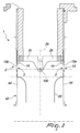
図面を参照すると、一般に参照番号1 で示されている本発明に係る取り出し装置は、靴下類等のための円形編機から管状のニット製品20を取り出すように構成されている。
With reference to the drawings, an apparatus for removing knitted products according to the present invention, generally designated by the
取り出し装置1 は環状の取り出し体2 を備えており、取り出し体2 は、取り出し体2 の軸芯2aの周りに配置された複数の取り出し部材3 を支持している。
The
取り出し体2 は、編機の夫々の針44と対応するように配置された取り出し部材3 の各々と共に靴下類等のための円形編機の針シリンダ42の周りに同軸に配置されるように構成されている。
The take-out
取り出し部材3 は、第1及び第2の環状部分2b, 2cによって支持されている。
The
第1及び第2の環状部分2b, 2cが取り出し装置の軸芯2aと同軸な円周を形成するように配置される取り出し状態(図1~図5参照)と第1及び第2の環状部分2b, 2cが互いに対向するように配置されるソーイング状態(図6~11参照)との間を通過すべく、第1及び第2の環状部分2b, 2cは、取り出し装置の軸芯2aに実質的に垂直な揺動軸芯100 を中心として互いに回転可能である。
The first and second
第1の環状部分2bは、複数の第1の取り出し部材3aを支持している。
The first
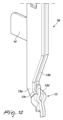
図12に拡大して示されている第1の取り出し部材3aは、並んで配置されている第1の取り出し要素13a 及び第2の取り出し要素13b を夫々有しており、第1の取り出し要素13a 及び第2の取り出し要素13b は、対応する針44から夫々の編成ループを外す間に、対応する針44に対して反対側に配置されるように構成されている。
The first removal member 3a, shown enlarged in FIG. 12, has a
第1の取り出し要素13a 及び第2の取り出し要素13b は、取り出し体2 の軸芯2aと実質的に平行な移動方向に夫々の針44に対して移動可能な取り出しヘッド13を形成している。
The first and
第1の取り出し要素13a は、対応する針44と係合する際に編成ループを係合して保持するように構成されているフック状部分13c を取り出しヘッド13に形成している。
The
第2の取り出し要素13b は、当接部分13d を取り外しヘッド13に有している。
The
当接部分13d は特に、夫々の編成ループをフック状部分13c から外すためにフック状部分13c に対して移動可能である。
The
好都合なことに、当接部分13d は、取り出し装置の軸芯2aと実質的に平行な移動方向にフック状部分13c に対して移動可能である。
Advantageously, the
各第1の取り出し部材3aは、取り出しヘッド13に対して移動可能な少なくとも1つの移動要素14を更に有しており、移動要素14は、環状部分2b, 2cがソーイング状態であるときに同一の第1の取り出し部材3aのフック状部分13c から外された編成ループを夫々の第2の取り出し部材3bに移すように構成されている。
Each first removal member 3a further has at least one moving
好都合なことに、移動要素14は、取り出し装置の軸芯2aに実質的に平行な移動方向に取り出しヘッド13に対して移動可能である。
Advantageously, the
好ましい実施形態によれば、各取り出し部材3a, 3bが対応する針44と係合する工程中、針シリンダ42の角速度と同一の角速度で軸芯2aを中心として指令で回転可能である。
According to a preferred embodiment, each extraction member 3a, 3b is commandably rotatable about the
このため、針44が最後の編成ループを供給する工程中に編成ループが針シリンダ42から取り出し部材に移される。
Therefore, the knitted loop is transferred from the
好都合なことに、第2の取り出し部材3bは少なくとも第2の取り出し要素を有しており、少なくとも第2の取り出し要素は、対応する針44と係合する際に編成ループを係合して保持するように構成されているフック状部分13c を取り出しヘッド13に形成している。
Advantageously, the second extraction member 3b has at least a second extraction element forming a hook-
好ましい実施形態によれば、第2の環状部分2cによって支持されている第2の取り出し部材は、第1の取り出し部材3aに対応するような形状を有し得る。
According to a preferred embodiment, the second extraction member supported by the second
好都合なことに、第2の取り出し部材3bは、取り出し体2 の軸芯2aと実質的に平行な移動方向に夫々の針44に対して移動可能な第2の取り出し要素13a, 13bを有している。
Advantageously, the second extraction member 3b has
移動要素14は、第1の取り出し要素13a 及び第2の取り出し要素13b 間に配置された押出薄片を有していることが有利である。
The moving
第2の取り出し部材3bは、夫々の取り出しヘッド13に対して移動可能な移動要素14を有しており、移動要素14は、第2の取り出し部材3bの取り出しヘッドのフック状部分13c から外す際の夫々の編成ループのための当接部として機能するように構成されている。
The second removal member 3b has a moving
一実施形態によれば、取り出し装置1 は、第1の取り出し部材3a及び第2の取り出し部材3bを移動させるための選択的作動手段を備えている。
According to one embodiment, the
このような選択的作動手段は、例えば、取り出し部材を移動させるように構成されたカム装置と、取り出し部材を構成する様々な要素、例えば取り出しヘッド13、第1の取り出し要素13a 、第2の取り出し要素13b及び移動要素14とを有し得る。
Such selective actuation means may, for example, comprise a cam arrangement configured to move the ejection member and the various elements constituting the ejection member, such as the
好ましい実施形態によれば、第1の取り出し要素13a 及び第2の取り出し要素13b は、並んで配置されており、夫々の針44と係合した後、取り出し体2 の軸芯2aを基準として実質的に接線の方向に互いから離れる方向及び互いに近づく方向に移動可能である。
According to a preferred embodiment, the first and
このため、特に取り出しヘッド13を、取り出す夫々のループの下側に運ぶことが可能になる。
This makes it possible, in particular, to bring the
更に、この解決策により、針シリンダ42の針44のタイプ及び形状に関係なく、取り出し体2 を使用することが可能になる。
Furthermore, this solution makes it possible to use the
本発明に係る取り出し装置1 の動作は以下の通りである。
The operation of the take-out
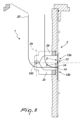
取り出し体2 (図1)は、環状部分が取り出し状態であるときに針シリンダ42と対向して針シリンダ42と軸方向に並んで配置される。
The removal body 2 (Figure 1) is positioned opposite the
取り出し体2 は、針シリンダ42の回転速度と同一の回転速度で自軸2a回りに回転する。
The
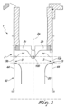
針シリンダ42が管状製品20の形成を終了すると、適切なカム装置が、取り出し部材3 を夫々の針44に向かって選択的に下降させる。
Once the
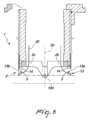
夫々の取り出しヘッド13(図2)が下降することにより、夫々の針44のフックと係合し、下降動作(図3)を続けることによって、編成ループをフック状部分13c に引き込む。
As each pick-up head 13 (Fig. 2) descends, it engages the hook of each
このとき(図4)、取り出し体2 は、針シリンダ42から離れる方向に移動すべく上昇し、管状製品20は裏表になる(図5)。
At this time (Figure 4), the
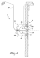
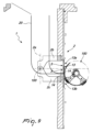
このとき(図6)、環状部分は、取り出し状態からソーイング状態に移動すべく、揺動軸芯100 を中心として相対的に回転する。
At this time (Figure 6), the annular portion rotates relatively around the
第1の環状部分2bの第2の取り出し要素13b が上昇し、夫々のフック状部分13c から編成ループを外す(図7)。
The
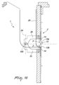
第1の取り出し要素13a に関連付けられている移動要素14が下降し(図8)、編成ループを第2の取り出し要素13b に向かって移す。
The moving
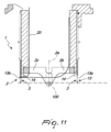
その後、ソーイングユニット150 が続けて編成ループを縫い合わせる(図9)。
The
このとき(図10)、第1の取り出し要素13a に関連付けられている移動要素14が上昇し、管状要素を解放する。
At this time (Figure 10), the
実際、本発明は、非常に実用的で有効な取り出し装置を提供することにより、対象とする意図及び目的を達成することが分かっている。 Indeed, the present invention has been found to achieve its intended aims and objectives by providing a highly practical and effective removal device.
このようにして考案された本発明は、その全てが添付した請求項の範囲内にある多くの修正及び変更を加えることができ、また細部の全ては、更に他の技術的に等価な要素に置き換えられてもよい。 The invention thus conceived is susceptible to numerous modifications and variations, all of which are within the scope of the appended claims, and all of the details may further be replaced by other technically equivalent elements.
実際、用いられる材料が特定の用途に適合する限り、用いられる材料並びに本質的でない形状及び寸法は、要件及び現状の技術に応じて如何なるものであってもよい。 In fact, the materials used and non-essential shapes and dimensions can be anything depending on the requirements and current technology, so long as the materials used are suitable for the particular application.
本出願が優先権を主張するイタリア特許出願第102019000023433 号明細書における開示内容は、参照として本明細書に盛り込まれる。 The disclosures in Italian Patent Application No. 102019000023433, from which this application claims priority, are hereby incorporated by reference.
任意の請求項に記載されている技術的特徴の後には参照符号が続いているが、これらの参照符号は、請求項の明瞭性を高めるためだけに含まれているものであり、従って、このような参照符号により一例として特定される各要素の解釈をいかなる形においても限定するものではない。 Where technical features described in any claim are followed by reference signs, these reference signs are included solely to enhance the clarity of the claims and therefore do not in any way limit the interpretation of the respective elements identified by such reference signs as examples.
Claims (8)
環状の取り出し体を備えており、前記取り出し体は、前記取り出し体の軸芯の周りに配置された複数の取り出し部材を支持しており、前記取り出し体は、靴下類のための円形編機の夫々の針に対応するように配置された前記取り出し部材の各々と共に、前記円形編機の針シリンダの周りに同軸に配置されるように構成されており、
前記取り出し部材は、第1の環状部分及び第2の環状部分によって支持されており、
前記第1の環状部分及び前記第2の環状部分が前記取り出し装置の軸芯と同軸な円周を形成するように配置される取り出し状態と前記第1の環状部分及び前記第2の環状部分が互いに対向するように配置されるソーイング状態との間を往復すべく、前記第1の環状部分及び前記第2の環状部分は、前記取り出し装置の軸芯に実質的に垂直な揺動軸芯を中心として互いに回転可能であり、
前記第1の環状部分は、並んで配置された第1の取り出し要素及び第2の取り出し要素を夫々有する複数の第1の取り出し部材を支持しており、
前記第1の取り出し要素及び前記第2の取り出し要素は、対応する針から夫々の編成ループを外す間に、対応する針に対して反対側に配置されるように構成されており、前記第1の取り出し要素及び前記第2の取り出し要素は、前記取り出し体の軸芯と実質的に平行な移動方向に夫々の針に対して移動可能な取り出しヘッドを形成しており、
前記第1の取り出し要素は、対応する針と係合する際に編成ループを係合して保持するように構成されているフック状部分を前記取り出しヘッドに形成しており、
前記第2の取り出し要素は、夫々の編成ループを前記フック状部分から外すべく、前記フック状部分に対して移動可能な当接部分を前記取り出しヘッドに有しており、
各第1の取り出し部材は、前記取り出しヘッドに対して移動可能な少なくとも1つの移動要素を有しており、前記少なくとも1つの移動要素は、前記第1の環状部分及び前記第2の環状部分がソーイング状態であるときに前記第1の取り出し部材のフック状部分から外された編成ループを夫々の第2の取り出し部材に移すように構成されている、取り出し装置。 1. A take-off device for taking off a tubular knitted product from a circular knitting machine for hosiery , comprising:
a circular take-up body supporting a plurality of take-up members arranged around an axis of the take-up body , the take-up body being adapted to be arranged coaxially around a needle cylinder of a circular knitting machine for hosiery , with each of the take-up members being arranged to correspond to a respective needle of the circular knitting machine,
the extraction member is supported by a first annular portion and a second annular portion ;
the first annular portion and the second annular portion are rotatable relative to each other about a pivot axis substantially perpendicular to the axis of the take-out device to reciprocate between a take-out state in which the first annular portion and the second annular portion are arranged to form a circumference coaxial with the axis of the take-out device and a sawing state in which the first annular portion and the second annular portion are arranged to face each other;
the first annular portion supports a plurality of first extraction members each having a first extraction element and a second extraction element arranged side by side;
the first and second removal elements are configured to be disposed on opposite sides of the corresponding needles during removal of the respective knitted loops from the corresponding needles , the first and second removal elements forming removal heads movable relative to the respective needles in a movement direction substantially parallel to an axis of the removal body ,
the first removal element forming a hook-like portion on the removal head configured to engage and hold a knitted loop upon engagement with a corresponding needle ;
the second removal element has an abutment portion on the removal head that is movable relative to the hook-like portion to disengage each knitted loop from the hook-like portion ;
The take-out device , wherein each first take-out member has at least one moving element movable relative to the take-out head , and the at least one moving element is configured to transfer the knitted loop released from the hook-shaped portion of the first take-out member to a respective second take-out member when the first annular portion and the second annular portion are in a sewing state.
前記移動要素は、前記第2の取り出し部材の取り出しヘッドのフック状部分から外す際の夫々の編成ループのための当接部として機能するように構成されている、請求項1~5のいずれか1つに記載の取り出し装置。 the second pick-up member has a moving element movable relative to the respective pick-up head ;
The extraction device according to any one of claims 1 to 5, wherein the moving element is configured to act as an abutment for a respective knitted loop upon disengagement from a hook-like portion of the extraction head of the second extraction member .
Applications Claiming Priority (3)
| Application Number | Priority Date | Filing Date | Title |
|---|---|---|---|
| IT102019000023433 | 2019-12-10 | ||
| IT102019000023433A IT201900023433A1 (en) | 2019-12-10 | 2019-12-10 | WITHDRAWER DEVICE TO TAKE A TUBULAR KNITTED PRODUCT FROM A CIRCULAR MACHINE FOR KNITWEAR, Hosiery OR SIMILAR |
| PCT/EP2020/084545 WO2021115933A1 (en) | 2019-12-10 | 2020-12-03 | Removal device for removing a knitted tubular manufacture from a circular knitting machine for hosiery or the like |
Publications (2)
| Publication Number | Publication Date |
|---|---|
| JP2023505625A JP2023505625A (en) | 2023-02-10 |
| JP7581318B2 true JP7581318B2 (en) | 2024-11-12 |
Family
ID=70009300
Family Applications (1)
| Application Number | Title | Priority Date | Filing Date |
|---|---|---|---|
| JP2022502987A Active JP7581318B2 (en) | 2019-12-10 | 2020-12-03 | Take-off device for removing tubular knitted products from a circular knitting machine for hosiery or the like |
Country Status (16)
| Country | Link |
|---|---|
| US (1) | US12091789B2 (en) |
| EP (1) | EP4073304B1 (en) |
| JP (1) | JP7581318B2 (en) |
| KR (1) | KR102761240B1 (en) |
| CN (1) | CN114466952B (en) |
| CO (1) | CO2022001041A2 (en) |
| ES (1) | ES2983552T3 (en) |
| HR (1) | HRP20240973T1 (en) |
| IT (1) | IT201900023433A1 (en) |
| MX (1) | MX2021015357A (en) |
| PL (1) | PL4073304T3 (en) |
| PT (1) | PT4073304T (en) |
| PY (1) | PY2082757A (en) |
| UA (1) | UA129824C2 (en) |
| WO (1) | WO2021115933A1 (en) |
| ZA (1) | ZA202201531B (en) |
Families Citing this family (1)
| Publication number | Priority date | Publication date | Assignee | Title |
|---|---|---|---|---|
| CN113737382B (en) * | 2021-08-10 | 2023-08-15 | 浙江罗速设备制造有限公司 | Tooth sewing needle for hosiery machine and use method |
Citations (2)
| Publication number | Priority date | Publication date | Assignee | Title |
|---|---|---|---|---|
| JP2003183955A (en) | 2001-10-17 | 2003-07-03 | Groz Beckert Kg | Plate for closing toe of stocking |
| US20160024695A1 (en) | 2013-04-12 | 2016-01-28 | Staubli Italia S.P.A. | Method and machine for knitting tubular knitted articles |
Family Cites Families (29)
| Publication number | Priority date | Publication date | Assignee | Title |
|---|---|---|---|---|
| US2895317A (en) * | 1955-03-24 | 1959-07-21 | Wildman Jacquard Co | Means for transferring loops in knitting machines |
| BG17822A3 (en) * | 1967-05-19 | 1973-12-25 | ||
| US3783644A (en) * | 1971-08-02 | 1974-01-08 | Wirkmaschinenbau Karl Marx Veb | Loop transfer means for circular knitting machines |
| US4116021A (en) | 1977-08-19 | 1978-09-26 | Marvel Specialty Company | Hosiery handling apparatus and method |
| US4250723A (en) | 1979-03-05 | 1981-02-17 | Marvel Specialty Company, Inc. | Apparatus for separating hosiery |
| IT1281598B1 (en) * | 1996-01-08 | 1998-02-20 | Matec Srl | CIRCULAR SINGLE-CYLINDER MACHINE FOR KNITWEAR OR SIMILAR, WITH HIGH VERSATILITY OF USE |
| ITFI980039A1 (en) * | 1998-02-20 | 1999-08-20 | Fabritex Srl | METHOD AND APPARATUS FOR JOINING THE EDGES OF KNITTED FABRICS. |
| IT1316679B1 (en) * | 2000-02-28 | 2003-04-24 | Matec Spa | PROCEDURE FOR THE PRODUCTION OF TUBULAR MANUFACTURES, IN PARTICULAR STOCKINGS, CLOSED IN CORRESPONDENCE OF AN AXIAL END WITH MACHINES |
| IT1316678B1 (en) * | 2000-02-28 | 2003-04-24 | Matec Spa | PROCEDURE AND EQUIPMENT FOR THE PRODUCTION OF TUBULAR MANUFACTURERS, IN PARTICULAR SOCKS, CLOSED IN CORRESPONDENCE WITH |
| TW548358B (en) * | 2000-08-22 | 2003-08-21 | Shima Seiki Mfg | Weft knitting machine with transfer mechanism and transferring method |
| ITFI20010143A1 (en) * | 2001-07-24 | 2003-01-24 | Fabritex Srl | METHOD AND DEVICE FOR HANDLING OR HANDLING THE SHIRTS OF A TEXTILE MANUFACTURE |
| ITFI20020199A1 (en) * | 2002-10-21 | 2004-04-22 | Fabritex Srl | METHOD AND APPARATUS TO JOIN THE EDGES OF A TUBULAR KNITTED FABRIC MANUFACTURE |
| US7025011B2 (en) * | 2003-01-24 | 2006-04-11 | B.B. & S Knitting Consultants | Apparatus for automatically orienting hosiery articles for closing toe ends thereof |
| DE10335464B4 (en) * | 2003-08-02 | 2006-06-14 | Groz-Beckert Kg | A method of machine stitching with associated stitch forming elements |
| ITMI20042495A1 (en) * | 2004-12-23 | 2005-03-23 | Santoni & C Spa | PROCEDURE FOR PERFORMING TRANSFER OF KNITTED PORTIONS PRODUCED BY A GROUP OF NEEDLES TO ANOTHER GROUP OF NEEDLES OF A FRONTING IN CIRCULAR KNITTING MACHINES OR FOR FOOTWEAR WITH TWO FRONT OR SIMILAR FOOTWEAR |
| ITMI20080399A1 (en) * | 2008-03-10 | 2009-09-11 | Lonati Spa | REVERSE DEVICE OF TUBULAR KNITTED MANUFACTURED ITEMS, PARTICULARLY FOR SEWING OR REPLACEMENT STATIONS FOR THE AUTOMATED CLOSING OF TUBULAR FACTORIES IN CORRESPONDENCE OF THEIR AXIAL END. |
| CN102046783A (en) | 2008-06-06 | 2011-05-04 | 丹尼斯科美国公司 | Compositions and methods comprising variant microbial proteases |
| CN101929028B (en) * | 2009-06-19 | 2014-10-29 | 马西莫·比安基 | Device and method for closing the toe at the end of a tubular knitted hosiery item |
| ITMI20130050A1 (en) * | 2013-01-16 | 2014-07-17 | Lonati Spa | PROCEDURE FOR IMPLEMENTING THE AUTOMATED CLOSURE OF AN AXIAL END OF A TUBULAR MANUFACTURE AND ITS EXHAUST UNDER REVERSE AND EQUIPMENT FOR ITS EXECUTION. |
| KR101783287B1 (en) * | 2014-08-29 | 2017-10-23 | 나가타세이키가부시키가이샤 | Circular knitting machine knitted fabric seaming method and circular knitting machine system |
| PT3204544T (en) * | 2014-10-10 | 2019-04-29 | Staeubli Italia S P A | Method and machine for knitting tubular knitted articles |
| ES2814101T3 (en) | 2015-01-28 | 2021-03-26 | Lonati Spa | Process for providing semi-finished tubular manufactured articles that are closed by sewing at an axial end thereof for the production of socks, and semi-finished tubular manufactured articles obtained by the process |
| DE102015105648A1 (en) * | 2015-04-14 | 2016-10-20 | Groz-Beckert Kg | Slide spring, slide, slide needle, guide arrangement and method for producing at least one slide spring |
| WO2017067801A1 (en) * | 2015-10-21 | 2017-04-27 | Staubli Italia S.P.A. | Device and method for picking up tubular knitted articles from circular knitting machines |
| ITUB20155479A1 (en) | 2015-11-11 | 2017-05-11 | Lonati Spa | PROCEDURE FOR THE PREPARATION OF A TUBULAR MANUFACTURE OF THE SOCK TYPE OR SIMILAR TO THE AUTOMATED COLLECTION AT THE END OF ITS FORMATION ON A CIRCULAR DOUBLE CYLINDER MACHINE WITH AT LEAST A FEEDING OR FALL AND A DOUBLE CYLINDER CIRCULAR MACHINE FOR ITS EXECUTION. |
| IT201600072994A1 (en) * | 2016-07-13 | 2018-01-13 | Lonati Spa | Pick-up device for picking up a knitted tubular product from a circular knitting, hosiery or similar machine and transferring it to a unit designed to perform further operations on the product. |
| CN107326518A (en) * | 2017-08-31 | 2017-11-07 | 宁波慈星股份有限公司 | A kind of apparatus and method that fabric is removed from knitting machine |
| CN208618050U (en) * | 2018-07-24 | 2019-03-19 | 杨志林 | A kind of tubing stitching devices with silica gel top plate |
| CN208829853U (en) * | 2018-07-24 | 2019-05-07 | 杨志林 | A kind of band dials the tubing stitching devices of hosiery machine structure |
-
2019
- 2019-12-10 IT IT102019000023433A patent/IT201900023433A1/en unknown
-
2020
- 2020-03-03 US US17/642,037 patent/US12091789B2/en active Active
- 2020-12-03 CN CN202080068816.1A patent/CN114466952B/en active Active
- 2020-12-03 MX MX2021015357A patent/MX2021015357A/en unknown
- 2020-12-03 PL PL20815887.3T patent/PL4073304T3/en unknown
- 2020-12-03 UA UAA202201284A patent/UA129824C2/en unknown
- 2020-12-03 JP JP2022502987A patent/JP7581318B2/en active Active
- 2020-12-03 ES ES20815887T patent/ES2983552T3/en active Active
- 2020-12-03 HR HRP20240973TT patent/HRP20240973T1/en unknown
- 2020-12-03 PT PT208158873T patent/PT4073304T/en unknown
- 2020-12-03 EP EP20815887.3A patent/EP4073304B1/en active Active
- 2020-12-03 WO PCT/EP2020/084545 patent/WO2021115933A1/en not_active Ceased
- 2020-12-03 KR KR1020227006582A patent/KR102761240B1/en active Active
- 2020-12-10 PY PY202002082757A patent/PY2082757A/en unknown
-
2022
- 2022-02-01 CO CONC2022/0001041A patent/CO2022001041A2/en unknown
- 2022-02-03 ZA ZA2022/01531A patent/ZA202201531B/en unknown
Patent Citations (2)
| Publication number | Priority date | Publication date | Assignee | Title |
|---|---|---|---|---|
| JP2003183955A (en) | 2001-10-17 | 2003-07-03 | Groz Beckert Kg | Plate for closing toe of stocking |
| US20160024695A1 (en) | 2013-04-12 | 2016-01-28 | Staubli Italia S.P.A. | Method and machine for knitting tubular knitted articles |
Also Published As
| Publication number | Publication date |
|---|---|
| PT4073304T (en) | 2024-07-29 |
| ES2983552T3 (en) | 2024-10-23 |
| MX2021015357A (en) | 2022-01-24 |
| US12091789B2 (en) | 2024-09-17 |
| JP2023505625A (en) | 2023-02-10 |
| HRP20240973T1 (en) | 2024-10-25 |
| EP4073304A1 (en) | 2022-10-19 |
| CN114466952A (en) | 2022-05-10 |
| US20240044055A1 (en) | 2024-02-08 |
| EP4073304B1 (en) | 2024-06-19 |
| BR112022008120A2 (en) | 2022-07-19 |
| IT201900023433A1 (en) | 2021-06-10 |
| PL4073304T3 (en) | 2024-11-04 |
| WO2021115933A1 (en) | 2021-06-17 |
| PY2082757A (en) | 2021-09-23 |
| CO2022001041A2 (en) | 2022-02-07 |
| CN114466952B (en) | 2024-08-09 |
| KR20220107152A (en) | 2022-08-02 |
| UA129824C2 (en) | 2025-08-13 |
| ZA202201531B (en) | 2022-10-26 |
| KR102761240B1 (en) | 2025-01-31 |
Similar Documents
| Publication | Publication Date | Title |
|---|---|---|
| US7954343B2 (en) | Method and apparatus for closing a tubular knitted article at one of its axial ends, at the end of its production cycle on a circular knitting machine for hosiery or the like | |
| CN101970740B (en) | Turning device for tubular knitted articles, especially for sewing or crocheting stations for automatically closing tubular articles at their axial ends | |
| KR101969740B1 (en) | Method for preparing a tubular manufacture such as a hosiery item or the like for automated pick-up at the end of its formation on a double-cylinder circular machine with at least one feed or drop and double-cylinder circular machine for performing the method | |
| CN101970739B (en) | Pick-up device for picking up tubular knitted items from a circular knitting machine for hosiery or the like and for transferring the tubular items to a unit suitable for additional processing on the items | |
| US20150354108A1 (en) | Method for Closing Automatically an Axial End of a Tubular Manufacture and for Unloading it in an Inside-out Configuration, and Apparatus for performing the Method | |
| CN109477261B (en) | The articles are picked up from the circular knitting machine of the hosiery and sent to the pick-up device of the operating unit | |
| JP7581318B2 (en) | Take-off device for removing tubular knitted products from a circular knitting machine for hosiery or the like | |
| TWI613140B (en) | Bobbin holder | |
| JP7568712B2 (en) | Take-off device for removing tubular knitted products from a circular knitting machine for hosiery or the like | |
| CN110230146B (en) | Footwear machine | |
| WO2008028575A1 (en) | Device for reversing tubular articles, particularly for circular knitting machines provided with a station for closing an axial end of the tubular article | |
| CN113286920A (en) | Pick-up device for picking up a tubular knitted article from a circular knitting machine and transferring it to a unit suitable for performing an additional operation on the article | |
| KR20150013493A (en) | Bead ring manufacturing device | |
| CN116892080B (en) | Picking device and picking method for removing and holding finished products from a hosiery machine | |
| CN118480899A (en) | Pickup device and pickup method for removing and holding a finished fabric from a hosiery machine | |
| BR112022008120B1 (en) | REMOVAL DEVICE FOR REMOVING A TUBULAR KNITTING GARMENT FROM A SOCK OR SIMILAR CIRCULAR KNITTING MACHINE | |
| EA047811B1 (en) | CIRCULAR KNITTING MACHINE FOR MAKING HOSIERY OR THE LIKE AND METHOD OF MAKING A TUBULAR PRODUCT | |
| JPH0550528A (en) | Bead filler forming device | |
| CN110791871A (en) | Pick-up device for picking up tubular knitted articles on a circular knitting machine and transferring them to another processing position |
Legal Events
| Date | Code | Title | Description |
|---|---|---|---|
| A621 | Written request for application examination |
Free format text: JAPANESE INTERMEDIATE CODE: A621 Effective date: 20231020 |
|
| A977 | Report on retrieval |
Free format text: JAPANESE INTERMEDIATE CODE: A971007 Effective date: 20240712 |
|
| A131 | Notification of reasons for refusal |
Free format text: JAPANESE INTERMEDIATE CODE: A131 Effective date: 20240716 |
|
| A521 | Request for written amendment filed |
Free format text: JAPANESE INTERMEDIATE CODE: A523 Effective date: 20241008 |
|
| TRDD | Decision of grant or rejection written | ||
| A01 | Written decision to grant a patent or to grant a registration (utility model) |
Free format text: JAPANESE INTERMEDIATE CODE: A01 Effective date: 20241022 |
|
| A61 | First payment of annual fees (during grant procedure) |
Free format text: JAPANESE INTERMEDIATE CODE: A61 Effective date: 20241030 |
|
| R150 | Certificate of patent or registration of utility model |
Ref document number: 7581318 Country of ref document: JP Free format text: JAPANESE INTERMEDIATE CODE: R150 |