JP7569413B2 - Method, apparatus and program for encoding and decoding blocks of video samples - Patents.com - Google Patents
Method, apparatus and program for encoding and decoding blocks of video samples - Patents.com Download PDFInfo
- Publication number
- JP7569413B2 JP7569413B2 JP2023105336A JP2023105336A JP7569413B2 JP 7569413 B2 JP7569413 B2 JP 7569413B2 JP 2023105336 A JP2023105336 A JP 2023105336A JP 2023105336 A JP2023105336 A JP 2023105336A JP 7569413 B2 JP7569413 B2 JP 7569413B2
- Authority
- JP
- Japan
- Prior art keywords
- intra prediction
- matrix
- current block
- matrix intra
- block
- Prior art date
- Legal status (The legal status is an assumption and is not a legal conclusion. Google has not performed a legal analysis and makes no representation as to the accuracy of the status listed.)
- Active
Links
Images


Classifications
-
- H—ELECTRICITY
- H04—ELECTRIC COMMUNICATION TECHNIQUE
- H04N—PICTORIAL COMMUNICATION, e.g. TELEVISION
- H04N19/00—Methods or arrangements for coding, decoding, compressing or decompressing digital video signals
- H04N19/10—Methods or arrangements for coding, decoding, compressing or decompressing digital video signals using adaptive coding
- H04N19/102—Methods or arrangements for coding, decoding, compressing or decompressing digital video signals using adaptive coding characterised by the element, parameter or selection affected or controlled by the adaptive coding
- H04N19/103—Selection of coding mode or of prediction mode
- H04N19/105—Selection of the reference unit for prediction within a chosen coding or prediction mode, e.g. adaptive choice of position and number of pixels used for prediction
-
- H—ELECTRICITY
- H04—ELECTRIC COMMUNICATION TECHNIQUE
- H04N—PICTORIAL COMMUNICATION, e.g. TELEVISION
- H04N19/00—Methods or arrangements for coding, decoding, compressing or decompressing digital video signals
- H04N19/10—Methods or arrangements for coding, decoding, compressing or decompressing digital video signals using adaptive coding
- H04N19/102—Methods or arrangements for coding, decoding, compressing or decompressing digital video signals using adaptive coding characterised by the element, parameter or selection affected or controlled by the adaptive coding
- H04N19/103—Selection of coding mode or of prediction mode
- H04N19/11—Selection of coding mode or of prediction mode among a plurality of spatial predictive coding modes
-
- H—ELECTRICITY
- H04—ELECTRIC COMMUNICATION TECHNIQUE
- H04N—PICTORIAL COMMUNICATION, e.g. TELEVISION
- H04N19/00—Methods or arrangements for coding, decoding, compressing or decompressing digital video signals
- H04N19/10—Methods or arrangements for coding, decoding, compressing or decompressing digital video signals using adaptive coding
- H04N19/102—Methods or arrangements for coding, decoding, compressing or decompressing digital video signals using adaptive coding characterised by the element, parameter or selection affected or controlled by the adaptive coding
- H04N19/13—Adaptive entropy coding, e.g. adaptive variable length coding [AVLC] or context adaptive binary arithmetic coding [CABAC]
-
- H—ELECTRICITY
- H04—ELECTRIC COMMUNICATION TECHNIQUE
- H04N—PICTORIAL COMMUNICATION, e.g. TELEVISION
- H04N19/00—Methods or arrangements for coding, decoding, compressing or decompressing digital video signals
- H04N19/10—Methods or arrangements for coding, decoding, compressing or decompressing digital video signals using adaptive coding
- H04N19/134—Methods or arrangements for coding, decoding, compressing or decompressing digital video signals using adaptive coding characterised by the element, parameter or criterion affecting or controlling the adaptive coding
- H04N19/146—Data rate or code amount at the encoder output
- H04N19/147—Data rate or code amount at the encoder output according to rate distortion criteria
-
- H—ELECTRICITY
- H04—ELECTRIC COMMUNICATION TECHNIQUE
- H04N—PICTORIAL COMMUNICATION, e.g. TELEVISION
- H04N19/00—Methods or arrangements for coding, decoding, compressing or decompressing digital video signals
- H04N19/10—Methods or arrangements for coding, decoding, compressing or decompressing digital video signals using adaptive coding
- H04N19/134—Methods or arrangements for coding, decoding, compressing or decompressing digital video signals using adaptive coding characterised by the element, parameter or criterion affecting or controlling the adaptive coding
- H04N19/157—Assigned coding mode, i.e. the coding mode being predefined or preselected to be further used for selection of another element or parameter
- H04N19/159—Prediction type, e.g. intra-frame, inter-frame or bidirectional frame prediction
-
- H—ELECTRICITY
- H04—ELECTRIC COMMUNICATION TECHNIQUE
- H04N—PICTORIAL COMMUNICATION, e.g. TELEVISION
- H04N19/00—Methods or arrangements for coding, decoding, compressing or decompressing digital video signals
- H04N19/10—Methods or arrangements for coding, decoding, compressing or decompressing digital video signals using adaptive coding
- H04N19/169—Methods or arrangements for coding, decoding, compressing or decompressing digital video signals using adaptive coding characterised by the coding unit, i.e. the structural portion or semantic portion of the video signal being the object or the subject of the adaptive coding
- H04N19/17—Methods or arrangements for coding, decoding, compressing or decompressing digital video signals using adaptive coding characterised by the coding unit, i.e. the structural portion or semantic portion of the video signal being the object or the subject of the adaptive coding the unit being an image region, e.g. an object
- H04N19/176—Methods or arrangements for coding, decoding, compressing or decompressing digital video signals using adaptive coding characterised by the coding unit, i.e. the structural portion or semantic portion of the video signal being the object or the subject of the adaptive coding the unit being an image region, e.g. an object the region being a block, e.g. a macroblock
-
- H—ELECTRICITY
- H04—ELECTRIC COMMUNICATION TECHNIQUE
- H04N—PICTORIAL COMMUNICATION, e.g. TELEVISION
- H04N19/00—Methods or arrangements for coding, decoding, compressing or decompressing digital video signals
- H04N19/10—Methods or arrangements for coding, decoding, compressing or decompressing digital video signals using adaptive coding
- H04N19/189—Methods or arrangements for coding, decoding, compressing or decompressing digital video signals using adaptive coding characterised by the adaptation method, adaptation tool or adaptation type used for the adaptive coding
- H04N19/196—Methods or arrangements for coding, decoding, compressing or decompressing digital video signals using adaptive coding characterised by the adaptation method, adaptation tool or adaptation type used for the adaptive coding being specially adapted for the computation of encoding parameters, e.g. by averaging previously computed encoding parameters
-
- H—ELECTRICITY
- H04—ELECTRIC COMMUNICATION TECHNIQUE
- H04N—PICTORIAL COMMUNICATION, e.g. TELEVISION
- H04N19/00—Methods or arrangements for coding, decoding, compressing or decompressing digital video signals
- H04N19/50—Methods or arrangements for coding, decoding, compressing or decompressing digital video signals using predictive coding
- H04N19/503—Methods or arrangements for coding, decoding, compressing or decompressing digital video signals using predictive coding involving temporal prediction
-
- H—ELECTRICITY
- H04—ELECTRIC COMMUNICATION TECHNIQUE
- H04N—PICTORIAL COMMUNICATION, e.g. TELEVISION
- H04N19/00—Methods or arrangements for coding, decoding, compressing or decompressing digital video signals
- H04N19/50—Methods or arrangements for coding, decoding, compressing or decompressing digital video signals using predictive coding
- H04N19/587—Methods or arrangements for coding, decoding, compressing or decompressing digital video signals using predictive coding involving temporal sub-sampling or interpolation, e.g. decimation or subsequent interpolation of pictures in a video sequence
-
- H—ELECTRICITY
- H04—ELECTRIC COMMUNICATION TECHNIQUE
- H04N—PICTORIAL COMMUNICATION, e.g. TELEVISION
- H04N19/00—Methods or arrangements for coding, decoding, compressing or decompressing digital video signals
- H04N19/50—Methods or arrangements for coding, decoding, compressing or decompressing digital video signals using predictive coding
- H04N19/593—Methods or arrangements for coding, decoding, compressing or decompressing digital video signals using predictive coding involving spatial prediction techniques
-
- H—ELECTRICITY
- H04—ELECTRIC COMMUNICATION TECHNIQUE
- H04N—PICTORIAL COMMUNICATION, e.g. TELEVISION
- H04N19/00—Methods or arrangements for coding, decoding, compressing or decompressing digital video signals
- H04N19/70—Methods or arrangements for coding, decoding, compressing or decompressing digital video signals characterised by syntax aspects related to video coding, e.g. related to compression standards
-
- H—ELECTRICITY
- H04—ELECTRIC COMMUNICATION TECHNIQUE
- H04N—PICTORIAL COMMUNICATION, e.g. TELEVISION
- H04N19/00—Methods or arrangements for coding, decoding, compressing or decompressing digital video signals
- H04N19/90—Methods or arrangements for coding, decoding, compressing or decompressing digital video signals using coding techniques not provided for in groups H04N19/10-H04N19/85, e.g. fractals
- H04N19/91—Entropy coding, e.g. variable length coding [VLC] or arithmetic coding
-
- H—ELECTRICITY
- H04—ELECTRIC COMMUNICATION TECHNIQUE
- H04N—PICTORIAL COMMUNICATION, e.g. TELEVISION
- H04N19/00—Methods or arrangements for coding, decoding, compressing or decompressing digital video signals
- H04N19/90—Methods or arrangements for coding, decoding, compressing or decompressing digital video signals using coding techniques not provided for in groups H04N19/10-H04N19/85, e.g. fractals
- H04N19/96—Tree coding, e.g. quad-tree coding
Landscapes
- Engineering & Computer Science (AREA)
- Multimedia (AREA)
- Signal Processing (AREA)
- Computing Systems (AREA)
- Theoretical Computer Science (AREA)
- Compression Or Coding Systems Of Tv Signals (AREA)
- Compression, Expansion, Code Conversion, And Decoders (AREA)
Description
関連出願への参照
本発明は、米国特許法第119条に基き、2019年6月24日に出願されたオーストラリア特許出願第2019204437号の利益を主張し、これにより、当該発明が本明細書に完全に記載されているものとする。
技術分野
REFERENCE TO RELATED APPLICATIONS This invention claims the benefit under 35 U.S.C. §119 of Australian Patent Application No. 2019204437, filed June 24, 2019, which is hereby incorporated by reference in its entirety as if fully set forth herein.
Technical Field
本発明は、一般に、デジタルビデオ信号処理に関し、特に、ビデオサンプルのブロックを符号化及び復号するための方法、装置に関する。本発明はまた、ビデオサンプルのブロックを符号化及び復号するためのコンピュータプログラムに関する。 The present invention relates generally to digital video signal processing, and in particular to methods and apparatus for encoding and decoding blocks of video samples. The present invention also relates to computer programs for encoding and decoding blocks of video samples.
現在、ビデオデータの送信及び記憶のためのアプリケーションを含む、ビデオコーディングのための多くのアプリケーションが存在する。多くのビデオコーディング標準が開発され、現在開発中のものも存在する。最近のビデオコーディングの標準化の進展により、「合同ビデオ専門家チーム」(JVET)と呼ばれるグループが結成された。合同ビデオ専門家チーム(JVET)には、「ビデオコーディング専門家グループ」(VCEG)として知られている国際電気通信連合(ITU)の電気通信標準化部門(ITU-T)第16研究委員会第6諮問(SG16/Q6)のメンバーと、「動画専門家グループ」(MPEG)として知られている国際標準化機構/国際電気標準会議の第1合同技術委員会/第29副委員会/第11作業部会(ISO/IEC JTC1/SC29/WG11)のメンバーが含まれる。 Currently, there are many applications for video coding, including applications for the transmission and storage of video data. Many video coding standards have been developed and are currently under development. Recent progress in video coding standardization has led to the formation of a group known as the "Joint Video Experts Team" (JVET). The Joint Video Experts Team (JVET) includes members of the International Telecommunication Union (ITU) Telecommunication Standardization Sector (ITU-T) Study Committee 16 Consultative Group 6 (SG16/Q6), known as the "Video Coding Experts Group" (VCEG), and members of the International Organization for Standardization/International Electrotechnical Commission Joint Technical Committee 1/Subcommittee 29/Working Group 11 (ISO/IEC JTC1/SC29/WG11), known as the "Moving Picture Experts Group" (MPEG).
合同ビデオ専門家チーム(JVET)は、提案募集(CfP)を行い、米国サンディエゴにおける第10回会議で応募された提案を分析した。応募された提案は、ビデオ圧縮機能が現在の最先端のビデオ圧縮標準、つまり「高効率ビデオコーディング」(HEVC)を大幅に上回っていることを示した。この分析結果に基づいて、「Versatile Video Coding」(VVC)という名前の新しいビデオ圧縮標準を開発するプロジェクトを開始することが決定された。VVCは、特にビデオ形式の機能が向上するにつれて(例えば、より高い解像度及びより高いフレームレート)、これまで以上に高い圧縮性能に対する継続的な需要に対応すると共に、帯域幅コストが比較的高いWANを介したサービス配信に対する市場の需要の高まりに対応することが期待されている。同時に、VVCは、従来のシリコンプロセスで実施可能であって、かつ、達成された性能と実施コスト(例えば、シリコン領域、CPUプロセッサの負荷、メモリ使用率、帯域幅など)との兼ね合いが許容できるものでなければならない。 The Joint Video Experts Team (JVET) issued a Call for Proposals (CfP) and analyzed the submitted proposals at its 10th conference in San Diego, USA. The submitted proposals showed that the video compression capabilities significantly exceed the current state-of-the-art video compression standard, i.e., "High Efficiency Video Coding" (HEVC). Based on the results of this analysis, it was decided to initiate a project to develop a new video compression standard named "Versatile Video Coding" (VVC). VVC is expected to address the continuing demand for ever higher compression performance, especially as video formats improve in capability (e.g., higher resolutions and higher frame rates), as well as the growing market demand for service delivery over WANs, where bandwidth costs are relatively high. At the same time, VVC must be implementable on conventional silicon processes and must provide an acceptable trade-off between the achieved performance and the implementation costs (e.g., silicon area, CPU processor load, memory utilization, bandwidth, etc.).
ビデオデータは、連続するフレームの画像データを含み、各フレームの画像データは、1以上のカラーチャネルを含む。一般に、1つの原色チャネルと2つの二次色チャネルが必要である。原色チャネルは一般に「ルマ」チャネルと呼ばれ、二次色チャネルは一般に「クロマ」チャネルと呼ばれる。ビデオデータは通常、RGB(赤-緑-青)色空間で表示されるが、この色空間は3つの各成分間で高い相関関係を有する。エンコーダまたはデコーダは、多くの場合、YCbCrなどの色空間を用いてビデオデータを表現する。YCbCrは、伝達関数に従って「ルマ」にマッピングされた輝度を、Y(一次)チャネルに集中させ、クロマをCb及びCr(二次)チャネルに集中させる。さらに、Cb、Crチャネルは、ルマチャネルと比較して、例えば、「4:2:0クロマフォーマット」として知られる、水平方向に半分、垂直方向に半分の、空間的に低いレートでサンプリング(サブサンプリング)され得る。4:2:0クロマフォーマットは、インターネットビデオストリーミング、テレビ放送、Blu-Ray(登録商標)ディスクへの保存などの「消費者向け」アプリケーションにおいて一般的に使用されている。Cb、Crチャネルを水平方向に半分のレートでサブサンプリングし、垂直方向にサブサンプリングしないフォーマットは、「4:2:2クロマフォーマット」として知られている。4:2:2クロマフォーマットは、通常、映画制作用の映像の撮影などを含む、プロ向けのアプリケーションで使用されている。4:2:2クロマフォーマットのサンプリングレートが高いほど、結果として得られる映像のカラーグレーディングなどの編集作業に対する柔軟性が高くなる。消費者に提供される前に、4:2:2クロマフォーマットの素材は、しばしば4:2:0クロマフォーマットに変換されてから、消費者に提供するために符号化される。クロマフォーマットに加えて、ビデオは解像度とフレームレートによっても特徴付けられている。解像度の例として、解像度が3840×2160の超高精細(UHD)、または、解像度が7680×4320の「8K」があり、フレームレートの例として、60Hzまたは120Hzがある。ルマサンプルレートは、例えば、毎秒約500メガサンプルから毎秒数ギガサンプルの間にある。4:2:0クロマフォーマットの場合、各クロマチャネルのサンプルレートは、ルマサンプルレートの4分の1であり、4:2:2クロマフォーマットの場合、各クロマチャネルのサンプルレートはルマサンプルレートの半分である。 Video data includes image data for successive frames, each of which includes one or more color channels. Generally, one primary color channel and two secondary color channels are required. The primary color channel is commonly called the "luma" channel, and the secondary color channel is commonly called the "chroma" channel. Video data is usually represented in the RGB (red-green-blue) color space, which has a high correlation between each of the three components. Encoders or decoders often represent video data using a color space such as YCbCr, which concentrates luminance, mapped to "luma" according to a transfer function, in the Y (primary) channel and chroma in the Cb and Cr (secondary) channels. Furthermore, the Cb and Cr channels may be sampled (subsampled) at a spatially lower rate than the luma channel, e.g., half horizontally and half vertically, known as the "4:2:0 chroma format". The 4:2:0 chroma format is commonly used in "consumer" applications such as Internet video streaming, television broadcasting, and storage on Blu-Ray discs. Formats in which the Cb, Cr channels are subsampled at half the rate horizontally and not subsampled vertically are known as "4:2:2 chroma formats". The 4:2:2 chroma format is typically used in professional applications, including filming footage for film productions. The higher sampling rate of the 4:2:2 chroma format allows more flexibility for editing tasks such as color grading the resulting footage. Before being delivered to consumers, material in the 4:2:2 chroma format is often converted to the 4:2:0 chroma format before being encoded for delivery to consumers. In addition to the chroma format, videos are also characterized by their resolution and frame rate. Example resolutions include ultra-high definition (UHD) with a resolution of 3840x2160, or "8K" with a resolution of 7680x4320, and example frame rates include 60 Hz or 120 Hz. Luma sample rates are, for example, between about 500 megasamples per second and several gigasamples per second. For a 4:2:0 chroma format, the sample rate of each chroma channel is one-quarter the luma sample rate, and for a 4:2:2 chroma format, the sample rate of each chroma channel is one-half the luma sample rate.
VVC規格は、「ブロックに基づく」符号化/復号であり、フレームは、まず、「符号木の単位(Coding Tree Unit)」(CTU)として知られる正方形の領域に分割される。CTUは通常、128×128のルマサンプルなどの比較的広い領域を占める。しかし、各フレームの右下端のCTUは、面積が小さい場合がある。各CTUには、ルマチャネルの「符号木」と、クロマチャネルの追加符号木が関連付けられている。符号木は、CTUの領域を、「符号化ブロック(Coding Block)」(CB)とも呼ばれるブロックの組に分解することを定義している。一つの符号木で、ルマチャネルとクロマチャネルの両方のブロックを特定することもでき、その場合、同じ場所にある符号化ブロックは、まとめて「符号化ユニット(Coding Unit)」(CU)と呼ばれる。つまり、各CUは、各カラーチャネルの符号化ブロックを有する。CBは、特定の順序で符号化処理または復号処理される。4:2:0クロマフォーマットを使用した場合、128×128のルマサンプル領域用のルマ符号木を有するCTUは、128×128のルマサンプル領域と同じ場所にある、64×64のクロマサンプル領域用の対応するクロマ符号木を有することになる。一つの符号木がルマチャネルとクロマチャネルに使用されている場合、ある領域と同じ位置にあるブロックの集合は、例えば、上記CUや、「予測単位(Prediction Unit)」(PU)、及び「変換単位(Transform Unit)」(TU)というように、一般に「単位」と呼ばれる。ある領域について別々の符号木を使用する場合、上記CBや、「予測ブロック(Prediction Block)」(PB)、及び「変換ブロック(Transform Block)」(TB)が用いられる。 The VVC standard is a "block-based" encoding/decoding where a frame is first divided into square regions known as "Coding Tree Units" (CTUs). A CTU typically occupies a relatively large area, such as 128x128 luma samples. However, the CTU at the bottom right corner of each frame may be smaller in area. Each CTU is associated with a "coding tree" for the luma channel and additional coding trees for the chroma channels. The coding trees define a decomposition of the CTU's region into a set of blocks, also called "coding blocks" (CBs). A coding tree may specify blocks for both the luma and chroma channels, in which case the co-located coding blocks are collectively referred to as a "coding unit" (CU). That is, each CU has a coding block for each color channel. The CBs are coded or decoded in a specific order. When using the 4:2:0 chroma format, a CTU with a luma code tree for a 128x128 luma sample region will have a corresponding chroma code tree for a 64x64 chroma sample region co-located with the 128x128 luma sample region. When a single code tree is used for the luma and chroma channels, the collection of blocks co-located with a region is commonly referred to as a "unit", e.g., the CU, Prediction Unit (PU), and Transform Unit (TU). When separate code trees are used for a region, the CB, Prediction Block (PB), and Transform Block (TB) are used.
なお、「単位」と「ブロック」との間に上記の区別があるが、「ブロック」という用語は、すべてのカラーチャネルに処理が適用されるフレームの領域を表す一般的な用語としても使用される。 Note that despite the above distinction between "units" and "blocks," the term "block" is also used as a general term to describe an area of a frame where processing is applied to all color channels.
各CUについて、フレームデータの対応する領域のコンテンツ(サンプル値)の予測単位(PU)が生成される(「予測単位」)。さらに、エンコーダへの入力時に見られる領域の予測とコンテンツとの間の差異(または空間ドメインにおける「残差」)を示すものが形成される。各カラーチャネルの差は、一連の残差係数として変換及び符号化され、あるCUについて1つ以上のTUを形成する。適用される変換は、離散コサイン変換(DCT)または他の変換であり、各ブロックの残差値に適用される。この変換は個別に適用される。つまり、二次元変換は2つのパスで実行される。ブロックは、まず、ブロック内の各行のサンプルに一次元変換を適用することによって変換される。次に、部分的な結果の各列に一次元変換を適用して当該部分的な結果を変換し、残差サンプルを実質的に無相関化する変換係数の最終的なブロックを生成する。さまざまなサイズの変換がVVC標準でサポートされており、これには、各辺の寸法が2のべき乗となる長方形のブロックの変換が含まれる。変換係数は、ビットストリームへのエントロピー符号化のために量子化される。 For each CU, a prediction unit (PU) of the content (sample values) of the corresponding region of the frame data is generated ("prediction unit"). In addition, a representation of the difference between the prediction and the content of the region as seen at the input to the encoder (or "residual" in the spatial domain) is formed. The differences in each color channel are transformed and coded as a set of residual coefficients, forming one or more TUs for a CU. The transform applied is a discrete cosine transform (DCT) or other transform, and is applied to the residual values of each block. This transform is applied independently; that is, the two-dimensional transform is performed in two passes. The block is first transformed by applying a one-dimensional transform to the samples of each row in the block. The partial result is then transformed by applying a one-dimensional transform to each column of the partial result to produce a final block of transform coefficients that substantially decorrelates the residual samples. Transforms of various sizes are supported in the VVC standard, including the transformation of rectangular blocks with each side dimension being a power of two. The transform coefficients are quantized for entropy coding into the bitstream.
VVCは、フレーム内予測及びフレーム間予測を特徴とする。フレーム内予測は、フレーム内の現ブロックのサンプルの予測値を生成するために使用されているフレーム内における、以前に処理されたサンプルの使用を含む。フレーム間予測は、以前に復号されたフレームから取得したブロックのサンプルを使用して、フレーム内の現ブロックのサンプルの予測値を生成することを含む。以前に復号されたフレームは、動きベクトルに従って現ブロックの空間位置からオフセットされ、多くの場合、フィルタ処理が適用されている。フレーム内予測ブロックは、均一なサンプル値(「DCイントラ予測」)であっても、オフセット及び水平及び垂直勾配を持つ平面(「平面イントラ予測」)であっても、または特定方向に隣接するサンプルが適用されたブロックの母集団(「角度イントラ予測」)、または、隣接するサンプルと選択された行列係数を使用した行列乗算の結果であってもよい。隣接するサンプルには以前に処理されたブロックからのサンプルが含まれるため、フレーム内予測のフィードバックループは大きく制限されており、サポートされる最高の解像度とフレームレートを満たすために必要なレベルよりも計算の複雑さを低く抑える必要がある。 VVC features intra-frame prediction and inter-frame prediction. Intra-frame prediction involves the use of previously processed samples in a frame that are used to generate a prediction of a sample of a current block in the frame. Inter-frame prediction involves using samples of a block taken from a previously decoded frame to generate a prediction of a sample of a current block in a frame. The previously decoded frame is offset from the spatial location of the current block according to a motion vector, and often has a filtered effect. An intra-frame predicted block may be a uniform sample value ("DC intra-prediction"), a plane with an offset and horizontal and vertical gradients ("planar intra-prediction"), or a population of blocks with neighboring samples in a particular direction ("angular intra-prediction"), or the result of a matrix multiplication using neighboring samples and selected matrix coefficients. Because the neighboring samples include samples from previously processed blocks, the feedback loop of intra-frame prediction is highly limited and requires a lower computational complexity than is necessary to meet the highest supported resolution and frame rate.
本発明の目的は、既存の構成の1つまたは複数の欠点を実質的に克服するか、または少なくとも改善することである。 The object of the present invention is to substantially overcome or at least ameliorate one or more shortcomings of existing arrangements.
本開示の一つの側面によれば、ビデオビットストリームから画像フレームのための符号木の符号化ユニットを復号する方法を提供し、前記方法は、前記符号木の領域を、各符号化ブロックが予測ブロックを含む、複数の符号化ブロックに分割する工程と、前記各符号化ブロックの前記予測ブロックについて、行列イントラ予測フラグを判断する工程であって、各行列イントラ予測フラグは、前記符号化ブロックのうちの1つの前記予測ブロックに行列イントラ予測が用いられたかを示し、前記判断を(i)前記領域が閾値を満たす場合には面積、または(ii)前記領域の面積が前記閾値を満たさない場合には前記領域の割当量に基づいて行い、前記判断されたフラグに応じて行列イントラ予測を用いると判断された各予測ブロックについて、メモリから行列係数を読み出す工程と、各予測ブロックの参照サンプル及び前記行列係数を用いて前記領域における各符号化ユニットについて生成された予測ブロックを用いて、符号化ユニットを復号する工程と、を含む。 According to one aspect of the present disclosure, there is provided a method for decoding coding units of a code tree for an image frame from a video bitstream, the method comprising: dividing a region of the code tree into a plurality of coding blocks, each coding block including a predictive block; determining a matrix intra prediction flag for the predictive block of each coding block, each matrix intra prediction flag indicating whether matrix intra prediction was used for one of the predictive blocks of the coding blocks, the determination being based on (i) an area of the region if the region meets a threshold, or (ii) an allocation of the region if the area of the region does not meet the threshold; for each predictive block determined to use matrix intra prediction according to the determined flag, reading matrix coefficients from a memory; and decoding the coding unit using a reference sample of each predictive block and a predictive block generated for each coding unit in the region using the matrix coefficients.
別の側面によれば、前記閾値は、512ルマサンプルよりも大きいサイズである。 According to another aspect, the threshold is a size greater than 512 luma samples.
別の側面によれば、前記閾値は、64ルマサンプルよりも大きいサイズである。 According to another aspect, the threshold is a size greater than 64 luma samples.
別の側面によれば、前記割当量では、前記領域について4×4ブロックの40ワードの読み出すことができる。 According to another aspect, the allocation allows for reading 40 words of a 4x4 block for the area.
別の側面によれば、行列イントラ予測が用いられた場合にのみ、前記CUの行列イントラ予測フラグは復号される。 In another aspect, the matrix intra prediction flag for the CU is decoded only if matrix intra prediction is used.
別の側面によれば、行列イントラ予測が用いられたかどうかに関わらず、前記CUの行列イントラ予測フラグは復号される。 In another aspect, the matrix intra prediction flag for the CU is decoded regardless of whether matrix intra prediction was used.
本開示の別の側面によれば、ビデオビットストリームから画像フレームのための符号木の符号化ユニットを復号する方法を提供し、前記方法は、前記符号木の領域を、それぞれが予測ブロックを含む、複数の符号化ブロックに分割する工程と、前記符号化ブロックの予測ブロックについて、各符号化ブロックのサイズに基づいて、行列イントラ予測フラグを判断する工程であって、各行列イントラ予測フラグは、前記対応する符号化ブロックの前記予測ブロックに行列イントラ予測が用いられたかを示し、前記判断されたフラグに応じて行列イントラ予測を用いると判断された各予測ブロックについて、メモリから行列係数を読み出す工程と、各予測ブロックの参照サンプル及び前記行列係数を用いて生成された前記領域における各符号化ユニットの予測ブロックから符号化ユニットを復号する工程と、を含む。 According to another aspect of the present disclosure, there is provided a method for decoding coding units of a code tree for an image frame from a video bitstream, the method comprising: dividing a region of the code tree into a plurality of coding blocks, each of which includes a predictive block; determining a matrix intra prediction flag for a predictive block of the coding blocks based on a size of each coding block, each matrix intra prediction flag indicating whether matrix intra prediction was used for the predictive block of the corresponding coding block; for each predictive block determined to use matrix intra prediction according to the determined flag, reading matrix coefficients from a memory; and decoding the coding unit from the predictive block of each coding unit in the region generated using a reference sample of each predictive block and the matrix coefficients.
別の側面によれば、前記符号化ユニットの前記サイズが4×4で無い場合に行列イントラ予測フラグは復号される。 According to another aspect, the matrix intra prediction flag is decoded if the size of the coding unit is not 4x4.
別の側面によれば、前記符号化ユニットの前記サイズが4×4、8×4、4×8のいずれかで無い場合に行列イントラ予測フラグは復号される。 In another aspect, the matrix intra prediction flag is decoded if the size of the coding unit is not 4x4, 8x4, or 4x8.
別の側面によれば、前記符号化ユニットの前記サイズが4×4、8×4、4×8、8×8のいずれかで無い場合に行列イントラ予測フラグは復号される。 According to another aspect, the matrix intra prediction flag is decoded if the size of the coding unit is not 4x4, 8x4, 4x8, or 8x8.
別の側面によれば、前記符号化ユニットの前記サイズが4×4、8×4、4×8、8×8、8×16のいずれかで無い場合に前記行列イントラ予測フラグは復号される。 According to another aspect, the matrix intra prediction flag is decoded if the size of the coding unit is not 4x4, 8x4, 4x8, 8x8, or 8x16.
本開示の別の側面によれば、ビデオビットストリームから画像フレームのための符号木の予測ブロックを生成する方法を提供し、前記方法は、前記ビットストリームから行列イントラ予測モードフラグを復号することにより前記符号化ユニットの予測モードを判断する工程と、予測モードは行列イントラ予測モードを含み、行列イントラ予測モードを判断するために短縮された二値符号語を復号する工程と、前記予測ブロックに隣接する参照サンプル及び前記復号された行列イントラ予測モードに応じて選択された行列に対して、行列乗算を行うことにより、予測ブロックを生成する工程と、を含む。 According to another aspect of the present disclosure, there is provided a method for generating a prediction block of a code tree for an image frame from a video bitstream, the method comprising: determining a prediction mode of the coding unit by decoding a matrix intra-prediction mode flag from the bitstream, the prediction mode including a matrix intra-prediction mode; decoding a shortened binary codeword to determine the matrix intra-prediction mode; and generating the prediction block by performing matrix multiplication on reference samples adjacent to the prediction block and a matrix selected according to the decoded matrix intra-prediction mode.
本開示の別の側面によれば、ビデオビットストリームから画像フレームのための符号木の符号化ユニットを復号する方法の方法を実施するためのコンピュータプログラムを格納した非一時的なコンピュータ可読記憶媒体を提供し、前記方法は、前記符号木の領域を、各符号化ブロックが予測ブロックを含む、複数の符号化ブロックに分割する工程と、前記各符号化ブロックの前記予測ブロックについて、行列イントラ予測フラグを判断する工程であって、各行列イントラ予測フラグは、前記符号化ブロックのうちの1つの前記予測ブロックに行列イントラ予測が用いられたかを示し、前記判断を(i)前記領域が閾値を満たす場合には面積、または(ii)前記領域の面積が前記閾値を満たさない場合には前記領域の割当量に基づいて行い、前記判断されたフラグに応じて行列イントラ予測を用いると判断された各予測ブロックについて、メモリから行列係数を読み出す工程と、各予測ブロックの参照サンプル及び前記行列係数を用いて前記領域における各符号化ユニットについて生成された予測ブロックを用いて、符号化ユニットを復号する工程と、を含む。 According to another aspect of the present disclosure, a non-transitory computer-readable storage medium is provided that stores a computer program for implementing a method of decoding coding units of a code tree for an image frame from a video bitstream, the method comprising: dividing a region of the code tree into a plurality of coding blocks, each coding block including a predictive block; determining a matrix intra prediction flag for the predictive block of each coding block, each matrix intra prediction flag indicating whether matrix intra prediction was used for one of the predictive blocks of the coding blocks, the determination being based on (i) an area of the region if the region meets a threshold, or (ii) an allocation of the region if the area of the region does not meet the threshold; for each predictive block determined to use matrix intra prediction according to the determined flag, reading matrix coefficients from a memory; and decoding the coding unit using a reference sample of each predictive block and a predictive block generated for each coding unit in the region using the matrix coefficients.
本開示の別の側面によれば、ビデオデコーダを提供し、ビデオビットストリームから画像フレームのための符号木の符号化ユニットを受信し、前記符号木の領域を、各符号化ブロックが予測ブロックを含む、複数の符号化ブロックに分割し、前記各符号化ブロックの前記予測ブロックについて、行列イントラ予測フラグを判断し、各行列イントラ予測フラグは、前記符号化ブロックうちの1つの前記予測ブロックに行列イントラ予測が用いられたかを示し、前記判断を(i)前記領域が閾値を満たす場合には面積、または(ii)前記領域の面積が前記閾値を満たさない場合には前記領域の割当量に基づいて行い、前記判断されたフラグに応じて行列イントラ予測を用いると判断された各予測ブロックについて、メモリから行列係数を読み出し、各予測ブロックの参照サンプル及び前記行列係数を用いて前記領域における各符号化ユニットについて生成された予測ブロックを用いて、符号化ユニットを復号する。 According to another aspect of the present disclosure, a video decoder is provided, receiving an encoding unit of a code tree for an image frame from a video bitstream, dividing a region of the code tree into a plurality of encoding blocks, each encoding block including a predictive block, determining a matrix intra prediction flag for the predictive block of each of the encoding blocks, each matrix intra prediction flag indicating whether matrix intra prediction was used for the predictive block of one of the encoding blocks, the determination being based on (i) an area of the region if the region meets a threshold, or (ii) an allocation of the region if the area of the region does not meet the threshold, reading matrix coefficients from a memory for each predictive block determined to use matrix intra prediction according to the determined flag, and decoding the encoding unit using a reference sample of each predictive block and a predictive block generated for each encoding unit in the region using the matrix coefficients.
本開示の別の側面によれば、システムを提供し、メモリと、プロセッサとを含み、前記プロセッサは、ビデオビットストリームから画像フレームのための符号木の符号化ユニットを復号する方法を実現するための、前記メモリに格納されたコードを実行し、前記方法は、前記符号木の領域を、各符号化ブロックが予測ブロックを含む、複数の符号化ブロックに分割する工程と、前記各符号化ブロックの前記予測ブロックについて、行列イントラ予測フラグを判断する工程であって、各行列イントラ予測フラグは、前記符号化ブロックのうちの1つの前記予測ブロックに行列イントラ予測が用いられたかを示し、前記判断を(i)前記領域が閾値を満たす場合には面積、または(ii)前記領域の面積が前記閾値を満たさない場合には前記領域の割当量に基づいて行い、前記判断されたフラグに応じて行列イントラ予測を用いると判断された各予測ブロックについて、メモリから行列係数を読み出す工程と、各予測ブロックの参照サンプル及び前記行列係数を用いて前記領域における各符号化ユニットについて生成された予測ブロックを用いて、符号化ユニットを復号する工程と、を含む。 According to another aspect of the present disclosure, a system is provided, comprising a memory and a processor, the processor executing code stored in the memory for implementing a method for decoding coding units of a code tree for an image frame from a video bitstream, the method comprising: dividing a region of the code tree into a plurality of coding blocks, each coding block including a predictive block; determining a matrix intra prediction flag for the predictive block of each coding block, each matrix intra prediction flag indicating whether matrix intra prediction was used for one of the predictive blocks of the coding blocks, the determination being based on (i) an area of the region if the region meets a threshold, or (ii) an allocation of the region if the area of the region does not meet the threshold; for each predictive block determined to use matrix intra prediction according to the determined flag, reading matrix coefficients from the memory; and decoding the coding unit using a reference sample of each predictive block and a predictive block generated for each coding unit in the region using the matrix coefficients.
他の側面も開示されている。 Other aspects have also been disclosed.
ここで、本発明の少なくとも1つの実施形態を、以下の図面及び付録を参照して説明する。 At least one embodiment of the present invention will now be described with reference to the following drawings and appendices.
最良の形態を含む詳細な説明
添付の図面のうちのいずれか1つまたは複数において、同じ参照番号を有するステップ及び/または特徴が参照される場合、それらのステップ及び/または特徴は、相反する意図が示されない限り、この明細書の目的のための同じ機能または動作を有する。
DETAILED DESCRIPTION INCLUDING BEST MODE When reference is made to steps and/or features having the same reference numbers in any one or more of the accompanying drawings, those steps and/or features have the same function or operation for purposes of this specification, unless a contrary intention is indicated.
上記のように、フレーム内予測の計算の複雑さは、特に行列イントラ予測(MIP)の場合に限られている。MIPはエラーを最小限に抑えるという点で効果的な解決方法を提供できるが、MIPを適用する計算の複雑さは、例えば4×4ブロックのみで構成されるフレームの、最悪の場合のブロック処理速度に特に影響を与える。ブロック処理速度は、目的とするアプリケーションの解像度とフレームレートをサポートするのに十分である必要がある。ルマチャネルのみを考えると、毎秒120フレームでの「8K」解像度のフレーム(7680×4320)では、毎秒248.8×10⁶個の4×4ブロックを処理する必要がある。フレームまたはビデオシーケンス全体で最悪の場合にならないとしても、最悪の場合に達した部分領域を、ディスプレイに表示用の完全に復号されたフレームの配信を遅らせることなく処理する必要がある。複雑さ理由の1つは、行列イントラ予測(MIP)モードに従って選択された行列係数を取り出すために必要なメモリ帯域幅に因るもので、これは、ブロック毎に制約無く異なり得る。 As mentioned above, the computational complexity of intraframe prediction is limited, especially in the case of matrix intraprediction (MIP). Although MIP can provide an effective solution in terms of minimizing errors, the computational complexity of applying MIP particularly impacts the worst-case block processing speed, for example for frames consisting of only 4x4 blocks. The block processing speed needs to be sufficient to support the resolution and frame rate of the intended application. Considering only the luma channel, a frame with "8K" resolution (7680x4320) at 120 frames per second needs to process 248.8x10⁶ 4x4 blocks per second. Even if the entire frame or video sequence does not reach the worst case, sub-regions that reach the worst case need to be processed without delaying the delivery of a fully decoded frame for display on the display. One reason for the complexity is due to the memory bandwidth required to retrieve the matrix coefficients selected according to the matrix intraprediction (MIP) mode, which can vary from block to block without constraint.
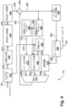
図1は、ビデオ符号化及び復号システム100の機能モジュールを示す概略ブロック図である。実用化、及び/または、MIPモードによって達成される符号化の利点に見合ったものにするために、システム100は、行列係数を選択または読み出すための最悪の場合のメモリ帯域幅を確立するために、MIPモードの適用に関わる制限を利用することができる。
Figure 1 is a schematic block diagram showing the functional modules of a video encoding and
システム100は、ソースデバイス110とディスティネーションデバイス130を含む。通信チャネル120は、符号化されたビデオ情報をソースデバイス110からディスティネーションデバイス130に通信するために用いられる。いくつかの構成では、ソースデバイス110とディスティネーションデバイス130のいずれかまたは両方は、携帯電話機または「スマートフォン」であってもよく、その場合、通信チャネル120は、無線チャネルである。他の構成では、ソースデバイス110及びディスティネーションデバイス130は、ビデオ会議機器であってもよく、その場合、通信チャネル120は、通常、インターネット接続などの有線チャネルである。さらに、ソースデバイス110及びディスティネーションデバイス130は、無線テレビ放送をサポートするデバイス、ケーブルテレビアプリケーション、インターネットビデオアプリケーション(ストリーミングを含む)、及び、符号化されたビデオデータがファイルサーバーのハードディスクドライブなど、コンピュータで読み取り可能なストレージメディアにキャプチャするアプリケーションを含む、広範囲のデバイスのいずれかであってもよい。
The
図1に示すように、ソースデバイス110は、ビデオソース112と、ビデオエンコーダ114と、送信機116とを含む。ビデオソース112は、典型的には、画像キャプチャセンサ、非一時的な記録媒体に保存された過去にキャプチャされたビデオシーケンス、またはリモート画像キャプチャセンサからの映像といった、キャプチャされたビデオフレームデータ(113として示される)のソースを含む。ビデオソース112はまた、例えば、オペレーティングシステムのビデオ出力や、例えばタブレットコンピュータ等のコンピューティングデバイス上で実行される様々なアプリケーションを表示する、コンピュータグラフィックスカードの出力であってもよい。画像キャプチャセンサをビデオソース112として含み得るソースデバイス110としては、スマートフォン、ビデオカムコーダー、プロ用ビデオカメラ、及びネットワークビデオカメラが含まれる。
As shown in FIG. 1, source device 110 includes
図3を参照してさらに説明するように、ビデオエンコーダ114は、ビデオソース112からのキャプチャされたフレームデータ(矢印113で示す)を、ビットストリーム(矢印115で示す)に変換(または「符号化」)する。ビットストリーム115は、符号化されたビデオデータ(または「符号化されたビデオ情報」)として、送信機116により通信チャネル120を介して送信される。ビットストリーム115を、後で通信チャネル120を介して送信されるまで、または通信チャネル120を介した送信の代わりに、「フラッシュ」メモリまたはハードディスクドライブなどの非一時的な記憶装置122に記憶することも可能である。例えば、符号化されたビデオデータは、ビデオストリーミングアプリケーションのために広域ネットワーク(WAN)を介して顧客にオンデマンドで提供することができる。
As further described with reference to FIG. 3, the
ディスティネーションデバイス130は、受信機132、ビデオデコーダ134、及び表示装置136を含む。受信機132は、符号化されたビデオデータを通信チャネル120から受信し、受信したビデオデータをビットストリームとしてビデオデコーダ134に渡す(矢印133で示す)。次に、ビデオデコーダ134は、復号したフレームデータ(矢印135で示す)を表示装置136に出力する。復号されたフレームデータ135は、フレームデータ113と同じクロマフォーマットを有する。表示装置136としては、例えば、陰極線管や、スマートフォン、タブレットコンピュータ、コンピュータモニター、スタンドアロンテレビ機器等の液晶ディスプレイ等を含む。また、ソースデバイス110及びディスティネーションデバイス130それぞれの機能を、例えば携帯電話やタブレットコンピュータ等の、単一機器で具現化することも可能である。
The destination device 130 includes a
上記例に挙げたデバイスに限られず、ソースデバイス110及びディスティネーションデバイス130はそれぞれ、汎用コンピューティングシステム内で、典型的にはハードウェアとソフトウェアコンポーネントの組み合わせを介して構成され得る。図2Aは、そのようなコンピュータシステム200を示しており、コンピュータモジュール201と、ビデオソース112として構成され得るキーボード202、マウスポインタデバイス203、スキャナ226及びカメラ227と、マイクロフォン280等の入力デバイスと、プリンタ215、表示装置136として構成され得るディスプレイデバイス214及びスピーカー217を含む出力デバイスを含む。外部変調器-復調器(モデム)トランシーバデバイス216は、コンピュータモジュール201が接続221を介して通信ネットワーク220と双方向の通信をするために使用され得る。通信チャネル120を代表する通信ネットワーク220は、インターネット、携帯通信ネットワーク、またはプライベートWANなどの(WAN)であってもよい。接続221が電話回線である場合、モデム216は、従来の「ダイヤルアップ」モデムであり得る。あるいは、接続221が大容量(例えば、ケーブルまたは光)接続である場合、モデム216は、ブロードバンドモデムであり得る。無線モデムを、通信ネットワーク220への無線接続のために使用してもよい。トランシーバデバイス216は、送信機116及び受信機132の機能を提供してもよく、通信チャネル120は、接続221として具現化され得る。
Without being limited to the above-mentioned exemplary devices, each of the source device 110 and the destination device 130 may be configured within a general-purpose computing system, typically through a combination of hardware and software components. FIG. 2A shows such a
コンピュータモジュール201は、典型的には、少なくとも1つのプロセッサユニット205及びメモリユニット206を含む。例えば、メモリユニット206は、半導体ランダムアクセスメモリ(RAM)及び半導体読み取り専用メモリ(ROM)を有し得る。コンピュータモジュール201はまた、ビデオディスプレイ214とスピーカー217とマイクロフォン280と結合するオーディオ-ビデオインターフェース207、キーボード202とマウス203とスキャナ226とカメラ227とオプションでジョイスティックまたは他のヒューマンインターフェースデバイス(図示せず)と結合するI/Oインターフェース213、外部モデム216及びプリンタ215向けのインターフェース208とを含む、多くの入力/出力(I/O)インターフェースを含む。オーディオ-ビデオインターフェース207からコンピュータモニタ214への信号は、一般に、コンピュータグラフィックスカードの出力である。いくつかの実装形態では、モデム216は、コンピュータモジュール201内、例えば、インターフェース208内に組み込まれ得る。コンピュータモジュール201はまた、ローカルネットワークインターフェース211を有し、これにより、コンピュータシステム200を接続223を介してローカルエリアネットワーク(LAN)として知られるローカル通信ネットワーク222に繋げることができる。図2Aに示されるように、ローカル通信ネットワーク222はまた、一般的にいわゆる「ファイアウォール」デバイスまたは同様の機能のデバイスを含む接続224を介して、ワイドネットワーク220に繋げることができる。ローカルネットワークインターフェース211は、Ethernet(登録商標)回路カード、Bluetooth(登録商標)無線構成、またはIEEE802.11無線構成を含んでもよい。しかしながら、他の多くのタイプのインターフェースをインターフェース211で用いてもよい。ローカルネットワークインターフェース211はまた、送信機116及び受信機132の機能を提供してもよく、通信チャネル120は、ローカル通信ネットワーク222において具体化され得る。
The
I/Oインターフェース208及び213は、シリアル接続及びパラレル接続のいずれかまたは両方を提供することができ、前者は、通常、ユニバーサルシリアルバス(USB)規格に従って実現され、対応するUSBコネクタ(不図示)を有する。記憶装置209は、通常、ハードディスクドライブ(HDD)210を含む。フロッピーディスクドライブや磁気テープドライブ(不図示)などの他の記憶装置も使用することができる。光ディスクドライブ212は、通常、不揮発性のデータソースとして機能するように提供される。光ディスク(CD-ROM、DVD、Blu ray Disc(登録商標)等)、USB-RAM、ポータブル外付けハードドライブ、フロッピーディスク等のポータブルメモリデバイスを、コンピュータシステム200の適切なデータソースとして使用することができる。典型的には、HDD210、光学ドライブ212、ネットワーク220及び222はいずれも、ビデオソース112として、またはディスプレイ214での再生用に格納される復号されたビデオデータの送信先として動作するように構成され得る。システム100のソースデバイス110及びディスティネーションデバイス130は、コンピュータシステム200により実現してもよい。
The I/O interfaces 208 and 213 can provide either or both serial and parallel connections, the former typically implemented according to the Universal Serial Bus (USB) standard and having a corresponding USB connector (not shown). The
コンピュータモジュール201の構成要素205から213は、典型的には、相互接続されたバス204を介して、当業者に知られているコンピュータシステム200の従来の動作モードとなる方法で通信する。例えば、プロセッサ205は、接続218を用いてシステムバス204に結合される。同様に、メモリ206及び光ディスクドライブ212は、接続219によってシステムバス204に結合される。説明された配置を実施できるコンピュータとしては、例えば、IBM-PCとその互換機、Sun SPARCstations、Apple Mac(登録商標)や同様のコンピュータシステムがある。
The
適切または所望された場合に、ビデオエンコーダ114及びビデオデコーダ134、及び以下に説明する方法は、コンピュータシステム200を使用して実現することができる。特に、ビデオエンコーダ114、ビデオデコーダ134及び説明する方法は、コンピュータシステム200内で実行可能な1以上のソフトウェアアプリケーションプログラム233として実現することができる。特に、ビデオエンコーダ114、ビデオデコーダ134、及び説明された方法の工程は、コンピュータシステム200内で実行されるソフトウェア233の命令231(図2Bを参照)によって実現できる。ソフトウェア命令231は、それぞれが1以上の特定のタスクを実行するための1以上のコードモジュールとして形成され得る。ソフトウェアはまた、第1の部分及び対応するコードモジュールが説明された方法を実行し、第2の部分及び対応するコードモジュールが第1の部分とユーザとの間のユーザインターフェースを管理する、2つの独立した部分に分割され得る。
Where appropriate or desired, the
ソフトウェアは、例えば、以下に説明する記憶装置を含む、コンピュータ可読媒体に記憶され得る。ソフトウェアは、コンピュータ可読媒体からコンピュータシステム200に読み出され、コンピュータシステム200によって実行される。コンピュータ可読媒体に記録されているそのようなソフトウェアまたはコンピュータプログラムを有するコンピュータ可読媒体は、コンピュータプログラム製品である。コンピュータシステム200においてコンピュータプログラム製品を使用することにより、ビデオエンコーダ114、ビデオデコーダ134、及び説明された方法を実行するために有利な装置に、有益な効果がもたらされる。
The software may be stored on a computer readable medium, including, for example, the storage devices described below. The software is read from the computer readable medium into the
ソフトウェア233は、通常、HDD210またはメモリ206に格納される。ソフトウェアは、コンピュータ可読媒体からコンピュータシステム200に読み出され、コンピュータシステム200によって実行される。従って、例えば、ソフトウェア233は、光ディスクドライブ212によって読み取られる光学的に読み取り可能なディスク記憶媒体(例えば、CD-ROM)225上に格納され得る。
The
場合によっては、アプリケーションプログラム233は、1つまたは複数のCD-ROM225上で符号化された状態でユーザに供給され、対応するドライブ212を介して読み取られてもよいし、あるいは、ネットワーク220または222からユーザによって読み取られてもよい。さらに、ソフトウェアは、他のコンピュータ可読媒体からコンピュータシステム200に読み出すこともできる。コンピュータ可読記憶媒体とは、記録された命令及び/またはデータを、実行及び/または処理するためにコンピュータシステム200に提供する、非一時的な有形記憶媒体を指す。このような記憶媒体としては、例えば、フロッピーディスク、磁気テープ、CD-ROM、DVD、Blu-ray Disc(登録商標)、ハードディスクドライブ、ROMまたは集積回路、USBメモリ、磁気光学ディスク、またはPCMCIAカード等のようなコンピュータ可読カードが含まれ、そのようなデバイスがコンピュータモジュール201の内部または外部のいずれにあってもよい。ソフトウェア、アプリケーションプログラム、命令及び/またはビデオデータまたは符号化されたビデオデータを、コンピュータモジュール401へ提供するために用いることができる一時的または無形のコンピュータ可読伝送媒体としては、例えば、無線または赤外線伝送チャネルや、別のコンピュータまたはネットワークデバイスへのネットワーク接続、及び電子メール送信やウェブサイト等に記録された情報を含むインターネットまたはイントラネットを含む。
In some cases, the
アプリケーションプログラム233の第2の部分及び上述した対応するコードモジュールは、ディスプレイ214上に描画または他の方法で表される1以上のグラフィカルユーザインターフェース(GUI)を実施するために実行され得る。そして、典型的にはキーボード202やマウス203の操作により、コンピュータシステム200及びアプリケーションのユーザは、機能的に適応可能な方法でインターフェースを操作して、GUIに関連するアプリケーションへの制御コマンド及び/または入力を提供することができる。スピーカー217を介して出力されたスピーチプロンプトやマイクロフォン280を介して入力されたユーザ音声コマンドを利用する音声インターフェース等、機能的に適応可能な他の形態のユーザインターフェースも実施され得る。
A second portion of the
図2Bは、プロセッサ205及び「メモリ」234の詳細な概略ブロック図である。メモリ234は、図2Aのコンピュータモジュール201がアクセス可能なすべてのメモリモジュール(HDD209及び半導体メモリ206を含む)の論理的集合体を表す。
Figure 2B is a detailed schematic block diagram of the
コンピュータモジュール201が最初に電源投入されると、電源投入時自己診断(POST)プログラム250が実行される。POSTプログラム250は、通常、図2Aの半導体メモリ206のROM249に格納されている。ソフトウェアを格納するROM249等のハードウェアデバイスは、ファームウェアと呼ばれることもある。POSTプログラム250は、コンピュータモジュール201内のハードウェアを検査して、適切に機能しているか確認し、プロセッサ205、メモリ234(209、206)、及び、典型的にはROM249に記憶されている基本的な入出力システムソフトウェア(BIOS)モジュール251が、正しく動作しているかをチェックする。POSTプログラム250が正常に実行されると、BIOS251は、図2Aのハードディスクドライブ210を起動する。ハードディスクドライブ210の起動により、ハードディスクドライブ210上に常駐するブートストラップローダープログラム252がプロセッサ205を介して実行される。これにより、オペレーティングシステム253はRAMメモリ206に読み出され、オペレーティングシステム253は動作を開始する。オペレーティングシステム253は、プロセッサ管理、メモリ管理、デバイス管理、ストレージ管理、ソフトウェアアプリケーションインターフェース、及び汎用ユーザインターフェースを含む、様々な高レベルな機能を実現するための、プロセッサ205によって実行可能なシステムレベルのアプリケーションである。
When the
オペレーティングシステム253は、コンピュータモジュール201で実行されている各処理及びアプリケーションが、別の処理に割り当てられたメモリと衝突することなく実行に十分なメモリを備えるように、メモリ234(209、206)を管理する。さらに、図2Aのコンピュータシステム200において利用可能なさまざまなタイプのメモリは、各処理を効果的に実行できるように適切に使用する必要がある。従って、集約メモリ234は、メモリの特定のセグメントがどのように割り当てられるかを説明することを意図するのではなく(特に明記しない限り)、コンピュータシステム200によってアクセス可能なメモリの概念及びどのように用いられるかを示すことを意図している。
The
図2Bに示すように、プロセッサ205は、制御ユニット239、算術論理ユニット(ALU)240、及びキャッシュメモリと呼ばれることもあるローカルまたは内部メモリ248を含む多数の機能モジュールを含む。キャッシュメモリ248は、通常、レジスタセクション内に多数のストレージレジスタ244-246を含む。1以上の内部バス241は、これらの機能モジュールを機能的に相互接続する。プロセッサ205はまた、典型的には、接続218を使用してシステムバス204を介して外部デバイスと通信するための1以上のインターフェース242を有する。メモリ234は、接続219を使用してバス204に結合される。
As shown in FIG. 2B, the
アプリケーションプログラム233は、条件付きの分岐及びループ命令を含み得る一連の命令231を含む。プログラム233は、プログラム233の実行に使用されるデータ232も含み得る。命令231及びデータ232は、それぞれ、メモリ位置228、229、230及び235、236、237に格納される。命令231とメモリ位置228-230の相対的なサイズに応じて、ある命令は、メモリ位置230に示す命令によって表されるように、単一のメモリ位置に格納され得る。あるいは、メモリ位置228及び229に示す命令のセグメントによって表されるように、命令を多数の部分に分割し、それぞれ別のメモリ位置に格納してもよい。
一般に、プロセッサ205には、その中で実行される一連の命令が与えられる。プロセッサ205は、次の入力を待ち、その入力に対して、プロセッサ205は、別の一連の命令を実行する。各入力は、多数のソースのうち1以上のソースから提供され、図2Aに示された、1以上の入力デバイス202、203によって生成されたデータ、ネットワーク220、202の一方を介して外部ソースから受信したデータ、記憶装置206、209の一方から取り出したデータ、または対応するリーダー212に挿入された記憶媒体225から取り出したデータを含む。一連の命令を実行すると、場合によってはデータが出力されることがある。実行により、データまたは変数をメモリ234に格納することもある。
In general, the
ビデオエンコーダ114、ビデオデコーダ134、及び説明された方法は、入力変数254を使用することができ、これらは、メモリ234の対応するメモリ位置255、256、257に格納される。ビデオエンコーダ114、ビデオデコーダ134、及び説明された方法は、出力変数261を生成し、これらは、メモリ234の対応するメモリ位置262、263、264に格納される。中間変数258は、メモリ位置259、260、266、及び267に格納され得る。
The
図2Bのプロセッサ205に戻り、レジスタ244、245、246、算術論理演算装置(ALU)240、及び制御ユニット239は、プログラム233を構成する命令セット内のすべての命令について、「取り出し、復号、実行」サイクルを行うために必要な一連のマイクロオペレーションを共同で行う。各取り出し、復号、実行のサイクルは、以下を含む。
メモリ位置228、229、230から命令231を取り出しまたは読み出す取り出し処理;
制御ユニット239がどの命令が取り出されたかを決定する復号処理;
制御ユニット239及び/またはALU240が命令を実行する実行処理。
Returning to
a fetch process that fetches or reads
a decode process in which control unit 239 determines which instructions have been fetched;
Execution process in which the control unit 239 and/or the
その後、次の命令のためのさらなる取り出し、復号、実行のサイクルが実行される。同様に、記憶サイクルを実行してもよく、これにより、制御ユニット239は値をメモリ位置232に記憶または書き込む。
A further fetch, decode, and execute cycle is then performed for the next instruction. Similarly, a store cycle may be performed, causing control unit 239 to store or write a value to
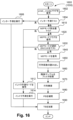
図11から図19の方法における各ステップまたはサブプロセスは、以下に説明するように、プログラム233の1以上のセグメントに関連付けられており、通常、プロセッサ205内のレジスタセクション244、245、247、ALU240、及び制御ユニット239が協働して、プログラム233の注記されたセグメントについて命令セット内のすべての命令について取り出し、復号、実行のサイクルを実行する。
Each step or sub-process in the methods of Figures 11-19 is associated with one or more segments of
図3は、ビデオエンコーダ114の機能モジュールを示す概略ブロック図である。図4は、ビデオデコーダ134の機能モジュールを示す概略ブロック図である。一般に、データは、ブロックを分割した固定サイズのサブブロックや行列などの、サンプルまたは係数のグループ単位で、ビデオエンコーダ114及びビデオデコーダ134内の機能モジュール間で受け渡しされる。ビデオエンコーダ114及びビデオデコーダ134は、図2A及び図2Bに示すように、汎用のコンピュータシステム200を使用して実施することができ、様々な機能モジュールが、システム200内の専用ハードウェアや、ハードディスクドライブ205上に常駐し、プロセッサ205による実行により制御される、ソフトウェアアプリケーションプログラム233の1以上のソフトウェアコードモジュール等の、コンピュータシステム200内で実行可能なソフトウェアにより実現され得る。あるいは、ビデオエンコーダ114及びビデオデコーダ134は、専用のハードウェアとコンピュータシステム200で実行可能なソフトウェアとの組み合わせによって実現され得る。あるいは、ビデオエンコーダ114、ビデオデコーダ134、及び説明された方法は、説明された方法の機能またはサブ機能を実行する1以上の集積回路等の専用ハードウェアで実現され得る。このような専用ハードウェアには、グラフィックプロセッシングユニット(GPU)、デジタル信号プロセッサ(DSP)、特定用途向け標準製品(ASSP)、特定用途向け集積回路(ASIC)、フィールドプログラマブルゲートアレイ(FPGA)、または1以上のマイクロプロセッサと関連メモリが含まれる。特に、ビデオエンコーダ114はモジュール310~392を含み、ビデオデコーダ134はモジュール420~496を含み、これらはそれぞれ、ソフトウェアアプリケーションプログラム233の1以上のソフトウェアコードモジュールとして実現され得る。
FIG. 3 is a schematic block diagram showing the functional modules of the
図3のビデオエンコーダは、Versatile Video Coding(VVC)のビデオコーディングパイプラインの例であるが、他のビデオコーデックを、本明細書に記載の処理段階を実行するために使用しても良い。ビデオエンコーダ114は、各フレームが1以上のカラーチャネルを含む一連のフレーム等の、キャプチャされたフレームデータ113を受信する。フレームデータ113は、任意のクロマフォーマット、例えば、4:0:0、4:2:0、4:2:2、または4:4:4クロマフォーマットであってよい。ブロック分割部310は、まず、フレームデータ113を、一般に正方形の形状であって、CTUのための特定のサイズが使用されるように構成されたCTUに分割する。CTUのサイズは、例えば、64×64、128×128、または256×256のルマサンプルである。ブロック分割部310はさらに、ルマ符号木及びクロマ符号木に応じて、各CTUを1以上のCBに分割する。CBにはさまざまなサイズがあり、正方形と非正方形アスペクト比の両方を含んでいてもよい。ブロック分割部310の動作は、図11乃至図19を参照してさらに説明される。ただし、VVC標準では、CB、CU、PU、及びTUの辺の長さは、常に2の累乗である。従って、312として表される現CBがブロック分割部310から出力され、CTUのルマ符号木及びクロマ符号木に従って、CTUの1以上のブロックにわたって反復することにより進行する。CTUをCBに分割するオプションについては、図5及び図6を参照して以下にさらに説明する。動作は全体的にCTU単位で記述されるが、ビデオエンコーダ114とビデオデコーダ134は、メモリ消費を削減するために、より小さなサイズの領域について動作することができる。例えば、各CTUは、サイズ64×64の「仮想パイプラインデータ単位」(VPDU)と呼ばれる、より小さな領域に分割することができる。VPDUは、ハードウェアアーキテクチャでのパイプライン処理により適した小ささのデータを形成し、これにより、CTU全体に処理を行う場合と比較して、メモリフットプリントの削減によりシリコン領域、ひいてはコストが削減される。
The video encoder of FIG. 3 is an example of a video coding pipeline for Versatile Video Coding (VVC), although other video codecs may be used to perform the processing steps described herein. The
フレームデータ113を1回分割して生じるCTUは、ラスタースキャン順にスキャンされ、1以上の「スライス」にグループ化され得る。スライスは「イントラ」(または「I」)スライスかもしれない。イントラスライス(Iスライス)は、スライス内のすべてのCUがイントラ予測されることを示す。あるいは、スライスは、単方向予測または双方向予測(それぞれ「P」または「B」スライス)されてもよく、それぞれスライス内の単方向予測及び双方向予測の可能性を更に示す。
The CTUs resulting from one division of the
各CTUについて、ビデオエンコーダ114は2段階で動作する。第1段階(「検索」段階と呼ぶ。)において、ブロック分割部310は、符号木の様々な潜在的構成をテストする。符号木の各潜在的構成には、「候補」CBが関連付けられている。第1段階では、様々な候補CBをテストして、比較的低い歪みで比較的高い圧縮効率となるCBを選択する。テストは一般的にラグランジュ最適化を含み、候補CBは、レート(符号化コスト)と歪み(入力フレームデータ113に対するエラー)の重み付けされた組み合わせに基づいて評価される。「最良の」候補CB(評価されたレート/歪みが最も低いCB)が、ビットストリーム115への次の符号化のために選択される。候補CBの評価には、所定のエリアにCBを使用するか、または、様々な分割オプションに従って領域をさらに分割し、結果として得られる小さいエリアをそれぞれCBでさらに符号化する、または、領域をさらに分割する、といったオプションが含まれる。その結果、CBと符号木の両方が共に検索段階で選択される。
For each CTU, the
ビデオエンコーダー114は、各CB、例えば、CB312について、矢印320によって示される予測ブロック(PB)を生成する。PB320は、関連するCB312の内容の予測である。減算モジュール322は、324(または「残差」、空間ドメインにある差異を指す)として示されるPB320とCB312との差異を生成する。差異324は、PB320とCB312における対応するサンプル間のブロックサイズの差異である。差異324は、変換され、量子化され、矢印336によって示される変換ブロック(TB)として表される。PB320及び関連するTB336は、通常、例えば評価されたコストまたは歪みに基づいて、多くの可能な候補CBのうちの1つから選択される。
For each CB, e.g.,
候補符号化ブロック(CB)は、関連するPB及び結果として生じる残差についてビデオエンコーダ114が利用可能な予測モードの1つから生じるCBである。TB336は、差異324を量子化し変換された表現である。ビデオデコーダ114において予測されたPBと組み合わされると、ビットストリームにシグナリングを追加することで、TB336は、復号されたCBと元のCB312との間の差異を低減する。
A candidate coding block (CB) is a CB resulting from one of the prediction modes available to the
従って、各候補符号化ブロック(CB)、すなわち、予測ブロック(PB)と変換ブロック(TB)の組み合わせは、関連する符号化コスト(または「レート」)と、関連する差異(または「歪み」)を有する。レートは通常ビット単位で測定される。CBの歪みは、通常、絶対差の合計(SAD)や二乗差の合計(SSD)など、サンプル値の差として推定される。各候補PBから生じる推定値は、予測モード387を決定するために、差324を使用してモードセレクタ386によって決定され得る。予測モード387は、現CBについて、フレーム内予測、フレーム間予測、または行列イントラ予測(MIP)を使用する決定を示す。予測モード387は、関連する動きベクトルを伴う、イントラ予測(行列イントラ予測、DC、平面、及び角度イントラ予測を含む)またはインター予測を含む可能なモードの中から選択されたモードとして決定される。予測モード387は、通常、関連するレートをラムダ値でスケーリングした結果と合計された各候補モードから生じる歪みのラグランジュ最適化の結果として得られる歪みメトリックを最小化することによって選択される。行列イントラ予測が使用されている場合、現CBに対して、使用可能ないくつかの行列イントラ予測モードのどれが使用されているかを示すために、行列イントラ予測モード(矢印388で表される)も決定される。ブロック、特に比較的小さいブロックのためのMIPモードの使用及び選択を決定するための検索は、図11乃至図14、そして、別の例では図17及び図18を参照して説明されるように、制約のない検索と比較して、行列係数を取り出すための最悪の場合のメモリ帯域幅を緩和するように制約され得る。各候補予測モード及び対応する残差の符号化に関連する符号化コストの推定は、残差のエントロピー符号化よりも大幅に少ないコストで実行することができる。従って、いくつかの候補モードを評価することで、レート対歪みの点で最適なモードを決定することができる。
Thus, each candidate coding block (CB), i.e., combination of prediction block (PB) and transform block (TB), has an associated coding cost (or "rate") and an associated difference (or "distortion"). The rate is usually measured in bits. The distortion of a CB is usually estimated as a difference of sample values, such as sum of absolute differences (SAD) or sum of squared differences (SSD). The estimated values resulting from each candidate PB may be determined by a mode selector 386 using the
レート対歪みの観点からの最適モードの決定は、通常、様々なラグランジュ最適化を使用して行われる。行列イントラ予測モード388の選択に際して、特定の行列イントラ予測モードを適用することにより生じる残差データの符号化コストの決定が通常行われる。符号化コストは、「絶対変換差の合計」(SATD)を使用して概算することができ、これにより、アダマール変換などの比較的単純な変換を使用して、推定変換残差コストを得ることができる。比較的単純な変換を使用するいくつかの場合において、単純化された推定方法から生じるコストは、完全な評価から決定される実際のコストに単調に関連している。単調に関連する推定コストを伴う場合では、簡略化された推定方法を使用して、ビデオエンコーダ114における複雑さを軽減しつつ、同じ決定(つまり、イントラ予測モード)を行うことができる。推定コストと実際のコストとの関係で起こりうる非単調性を受け入れるために、簡略化された推定方法を使用して、最良の候補のリストを生成することができる。非単調性は、例えば、残差データの符号化に利用可能なさらなるモードの決定から生じる可能性がある。リスト中の最良の候補の数は、任意の数であってよい。最良の候補を使用してより完全な検索を実行することで、各候補の残差データを符号化するための最適なモードの選択肢を確立し、これにより、他のモード決定と共にイントラ予測モードの最終選択が可能となる。
The determination of the optimal mode in terms of rate versus distortion is typically made using various Lagrangian optimizations. Upon selection of the matrix intra prediction mode 388, a determination of the coding cost of the residual data resulting from applying the particular matrix intra prediction mode is typically made. The coding cost can be approximated using the "sum of absolute transform differences" (SATD), which allows for an estimated transformed residual cost to be obtained using a relatively simple transform such as the Hadamard transform. In some cases using a relatively simple transform, the cost resulting from the simplified estimation method is monotonically related to the actual cost determined from the full evaluation. In cases with monotonically related estimated costs, the simplified estimation method can be used to make the same decision (i.e., intra prediction mode) while reducing the complexity in the
他のモード決定には、「変換スキップ」として知られる前方変換をスキップする機能が含まれる。変換のスキップは、変換基底関数等の式を用いて符号化コストを削減するための十分な相関関係が無い残差データに適している。コンピューターで生成された比較的単純なグラフィックス等の特定の種類のコンテンツは、同様の性質を示す場合がある。「スキップされた変換」の場合、変換自体が実行されなくても、残差係数は符号化される。 Other mode decisions include the ability to skip the forward transform, known as "transform skip". Transform skipping is appropriate for residual data that is not sufficiently correlated to reduce the coding cost using expressions such as transform basis functions. Certain types of content, such as relatively simple computer-generated graphics, may exhibit similar properties. In the case of "skipped transform", the residual coefficients are still coded even though the transform itself is not performed.
ラグランジアンまたは同様の最適化処理を使用して、(ブロック分割部310による)CTUのCBへの最適な分割の選択、ならびに複数の可能性から最良の予測モードの選択の両方を行うことができる。モード選択モジュール386における候補モードのラグランジュ最適化プロセスの適用を通じて、最も少ないコスト量のイントラ予測モードが「最良の」モードとして選択される。最少コストモードは、選択されたイントラ予測モード388であり、エントロピーエンコーダ338によってビットストリーム115に符号化される。モードセレクタモジュール386の動作によるイントラ予測モード388の選択は、ブロック分割部310の動作にまで及ぶ。例えば、イントラ予測モード388の選択の候補は、所定ブロックに適用可能なモードと、所定ブロックと同じ位置にある複数のより小さなブロックに適用可能な追加モードを含み得る。所定ブロック及び同じ位置にあるより小さなブロックに適用可能なモードを含む場合、候補を選択する処理は、非明示的には、CTUからCBへの最良の階層的分解を決定する処理でもある。
A Lagrangian or similar optimization process can be used to both select the optimal partitioning of the CTU into CBs (by the block partitioner 310) as well as to select the best prediction mode from multiple possibilities. Through application of a Lagrangian optimization process of the candidate modes in the mode selection module 386, the intra prediction mode with the least amount of cost is selected as the "best" mode. The least cost mode is the selected intra prediction mode 388 and is encoded into the
ビデオエンコーダ114の動作の第2段階(「符号化」段階と呼ばれる)では、選択されたルマ符号木及び選択されたクロマ符号木、すなわち、選択された各CBの反復処理が、ビデオエンコーダ114において行われる。反復処理において、CBは、ここでさらに説明されるように、ビットストリーム115に符号化される。
In a second stage of operation of the video encoder 114 (called the "encoding" stage), an iterative process of the selected luma code tree and the selected chroma code tree, i.e., each selected CB, is performed in the
エントロピーエンコーダ338は、構文要素の可変長符号化と構文要素の算術符号化の両方をサポートする。算術符号化は、コンテキスト適応型の二値化算術符号化処理を使用してサポートされる。算術的に符号化された構文要素は、1以上の「ビン」のシーケンスで構成される。ビンは、ビットと同様に、「0」または「1」の値を持つ。ただし、ビンは離散ビットとしてビットストリーム115にエンコードされることはない。ビンは、関連する予測(または「可能性が高い」または「最も可能性が高い」)値と、「コンテキスト」として知られる関連する確率とを有する。符号化される実際のビンが予測値と一致する場合、「最も可能性の高いシンボル」(MPS)が符号化される。最も可能性の高いシンボルの符号化は、ビットストリーム115で消費されるビットの点においてコストが比較的少なく、1離散ビット未満のコストも含まれる。符号化される実際のビンが想定される値と一致しない場合、「最も可能性の低いシンボル」(LPS)が符号化される。最も可能性の低いシンボルの符号化は、消費されるビットの点においてコストが比較的高くなる。ビンの符号化手法により、「0」対「1」の確率が偏っているビンの効率的な符号化が可能になる。2つの可能な値(つまり、「フラグ」)を持つ構文要素の場合、単一のビンで十分である。可能な値が多数ある構文要素の場合、一連のビンが必要となる。
The
シーケンスにおける後方のビンの存在は、シーケンスにおける前方のビンの値に基づいて決定することができる。さらに、各ビンは複数のコンテキストに関連付けられている場合がある。特定のコンテキストの選択は、構文要素内の前方のビン、隣接する構文要素のビン値(つまり、隣接するブロックからのビン値)などに依存する可能性がある。コンテキスト符号化されたビンが符号化される度に、そのビンに対して選択されたコンテキスト(存在する場合)は、新しいビン値を反映するように更新される。このように、バイナリ算術符号化スキームは適応性があると言える。 The presence of a later bin in the sequence can be determined based on the values of earlier bins in the sequence. Furthermore, each bin may be associated with multiple contexts. The selection of a particular context may depend on earlier bins in the syntax element, on bin values of neighboring syntax elements (i.e., bin values from neighboring blocks), etc. Each time a context-coded bin is coded, the context selected for that bin (if any) is updated to reflect the new bin value. In this way, binary arithmetic coding schemes are said to be adaptive.
コンテキストが無いビン(「バイパスビン」)もまた、ビデオエンコーダ114によってサポートされる。バイパスビンは、「0」と「1」が等確率分布であることを想定して符号化される。従って、各ビンはビットストリーム115の1ビットを占める。コンテキストがないため、メモリが節約されると共に複雑さが軽減されるため、特定のビンの値の分布が偏っていない場合は、バイパスビンが使用される。コンテキストと適応を採用するエントロピーコーダーの一例は、当技術分野ではCABAC(コンテキスト適応バイナリ算術コーダー)として知られており、このコーダーの多くの変形例がビデオ符号化に採用されてきた。
Context-free bins ("bypass bins") are also supported by the
エントロピーエンコーダ338は、予測モード387を符号化し、現CBに使用されている場合、コンテキスト符号化及びバイパス符号化されたビンの組み合わせを使用して、行列イントラ予測モード388を符号化する。サイズ4×4のブロックは、35の可能な行列イントラ予測モードを有し、サイズが8×8を超えないブロック(つまり、4×8、8×4、及び8×8)は、19の可能な行列イントラ予測モードを有する。他のブロックサイズの場合、11の可能な行列イントラ予測モードがある。通常、「最も可能性の高い行列モード」(MPM)のリストは、ビデオエンコーダ114で生成される。最も可能性の高いモードのリストは、通常、3つのモードなど、固定長である。最も可能性の高いモードのリストは、現ブロックに隣接する先のブロックにおけるモードを含み得る。例えば、現ブロックの上または左のブロックをMIPモードで使用する場合、対応するモードが現ブロックのMPMとして存在する。現ブロックの上または左のブロックを角度イントラ予測で使用する場合、現ブロックのMPMリストは、角度イントラ予測モードをMIPモードにマッピングするルックアップテーブルを介して導出されたMIPモードで埋められる。さらに、通常のイントラ予測(DC、平面、または角度)を使用して予測された後続のCUのMPMリストには、MIPモードから候補の通常のイントラ予測モードへのマッピングテーブルとともに、MIPモードを使用して符号化されたCUから派生したイントラ予測モードの候補を含めることができる。コンテキスト符号化されたビンは、イントラ予測モードが最も可能性の高いモードの1つであるかどうかを示すフラグを符号化する。イントラ予測モード388が最も可能性の高いモードの1つである場合、バイパス符号化されたビンを使用して、更にシグナリングが符号化される。符号化されたさらなるシグナリングは、例えば、短縮された1つのビンのストリングを使用して、最も可能性の高いモードのどれが行列イントラ予測モード388に対応するかを示す。それ以外の場合、イントラ予測モード388は「残りのモード」として符号化される。残りのモードとしての符号化では、バイパス符号化されたビンを使用して符号化された、固定長符号等の代替構文を使用して、最も可能性の高いモードリストに存在するもの以外のイントラ予測モードを表す。
The
いくつかの構成では、(MIPモードを使用して符号化された)現CUと、通常のイントラ予測モードを使用して符号化され、任意のMIPモードで符号化された近隣のブロックから派生したイントラ予測モードの候補を含み得る、後続のCUの両方のMPMリストの作成が複雑になることを回避できる。MPMリストの作成を省略すると、MIPモードの2値化は、MIPモードを表すために、短縮された二値符号を使用して実行される。短縮された二値符号では、各MIPモードの符号化コストが比較的均等になるが、MPMリストでは、MPMリストに追加された各MIPの符号化コストが低くなる。MIPモードの選択から得られた統計では、MPMリストに含まれていないMIPモードと比較して、MPMリストに含まれているMIPモードの選択に強い偏りがあるとは示されておらず、これは、MPMリストの生成を省略しても圧縮効率が低下しないことを示している。4×4ブロックの場合、35の可能なMIPモードを、5ビットまたは6ビットの符号を用いて符号化でき、MIPモード0~28では5ビット、MIPモード29~34では6ビットを用いる。4×8、8×4、及び8×8ブロックの場合、19の可能なMIPモードを、4ビットまたは5ビットの符号を用いて符号化でき、MIPモード0~12では4ビット、MIPモード13~18では5ビットを用いる。他のサイズのブロックの場合、11個の可能なMIPモードを、3ビットまたは4ビットの符号を用いて符号化でき、MIPモード0~4では3ビット、MIPモード5~10では4ビットを用いる。 In some configurations, it is possible to avoid the complexity of creating MPM lists for both the current CU (coded using an MIP mode) and subsequent CUs, which are coded using a normal intra prediction mode and may contain intra prediction mode candidates derived from neighboring blocks coded in any MIP mode. When the creation of the MPM list is omitted, the binarization of the MIP modes is performed using shortened binary codes to represent the MIP modes. The shortened binary codes make the coding cost of each MIP mode relatively equal, whereas the MPM list reduces the coding cost of each MIP added to the MPM list. Statistics obtained from the selection of MIP modes do not show a strong bias in the selection of MIP modes included in the MPM list compared to MIP modes not included in the MPM list, which indicates that omitting the generation of the MPM list does not reduce the compression efficiency. For a 4x4 block, 35 possible MIP modes can be coded using 5-bit or 6-bit codes, with 5 bits for MIP modes 0-28 and 6 bits for MIP modes 29-34. For 4x8, 8x4, and 8x8 blocks, the 19 possible MIP modes can be encoded using a 4-bit or 5-bit code, with MIP modes 0-12 using 4 bits and MIP modes 13-18 using 5 bits. For blocks of other sizes, the 11 possible MIP modes can be encoded using a 3-bit or 4-bit code, with MIP modes 0-4 using 3 bits and MIP modes 5-10 using 4 bits.
マルチプレクサモジュール384は、決定された最良の予測モード387に従って各候補CBのテストされた予測モードから選択して、PB320を出力する。 候補予測モードは、ビデオエンコーダ114によってサポートされる考えられる予測モードをすべて含む必要は無い。
The
フレーム間予測では、ブロックの予測は、ビットストリームにおけるフレームを符号化する順序で、現フレームから先行する1~2フレームからのサンプルを使用して生成される。さらに、フレーム間予測では、通常、単一の符号木がルマチャネルとクロマチャネルの両方に用いられる。ビットストリームにおけるフレームを符号化する順序は、フレームがキャプチャまたは表示されるときの順序とは異なる場合がある。1つのフレームが予測に使用される場合、ブロックは「単方向予測」と呼ばれ、1つの関連する動きベクトルを有する。2つのフレームが予測に使用される場合、ブロックは「双方向予測」と呼ばれ、2つの関連するモーションベクトルを有する。Pスライスの場合、各CUはイントラ予測または単方向予測され得る。Bスライスの場合、各CUは、イントラ予測、単方向予測、または双方向予測され得る。フレームは通常、「画像のグループ」構造を用いて符号化され、これにより、フレームの時間的階層が可能になる。フレームの時間的階層により、フレームが、フレームを表示する順序で前後の画像を参照できるようになる。画像は、各フレームを復号するための依存関係を確実に満たすために必要な順序で符号化される。 In inter-frame prediction, a prediction for a block is generated using samples from one or two frames preceding the current frame in the order of encoding the frames in the bitstream. Furthermore, in inter-frame prediction, a single code tree is typically used for both luma and chroma channels. The order of encoding the frames in the bitstream may differ from the order in which the frames are captured or displayed. If one frame is used for prediction, the block is called "unidirectionally predicted" and has one associated motion vector. If two frames are used for prediction, the block is called "bidirectionally predicted" and has two associated motion vectors. For P slices, each CU can be intra-predicted or unidirectionally predicted. For B slices, each CU can be intra-predicted, unidirectionally predicted, or bidirectionally predicted. Frames are typically coded using a "group of pictures" structure, which allows for a temporal hierarchy of frames. The temporal hierarchy of frames allows frames to reference previous and next pictures in the order of displaying the frames. Pictures are coded in the order required to ensure that dependencies for decoding each frame are met.
サンプルは、動きベクトル及び参照画像インデックスに従って選択される。動きベクトルと参照画像インデックスはすべてのカラーチャネルに適用されるため、インター予測は、PBではなく、主にPUに対する処理の観点から説明される。各カテゴリ(つまり、フレーム内及びフレーム間予測)において、PUを生成するために異なる技術を適用することができる。例えば、イントラ予測は、先に再構築されたサンプルに隣接する行及び列からの値を、方向と組み合わせて使用することで、所定のフィルタ処理及び生成処理に従ってPUを生成する。あるいは、PUは少数のパラメータを用いて記述してもよい。インター予測方法は、モーションパラメータの数とその精度が異なる場合がある。モーションパラメータは通常、参照フレームのリストからどの参照フレームを使用するか、及び各参照フレームの空間変換を示す、参照フレームインデックスを含むが、より多くのフレーム、特別なフレーム、またはスケーリングや回転のような複雑なアフィンパラメータを含めることもできる。さらに、所定のモーションリファインメント処理を適用して、参照されたサンプルブロックに基づく高密度のモーション推定値を生成してもよい。 Samples are selected according to a motion vector and a reference image index. Inter prediction is primarily described in terms of processing on PUs, not PBs, since the motion vector and reference image index apply to all color channels. In each category (i.e., intraframe and interframe prediction), different techniques can be applied to generate PUs. For example, intra prediction uses values from rows and columns adjacent to the previously reconstructed samples, in combination with an orientation, to generate PUs according to a predefined filtering and generation process. Alternatively, PUs may be described using a small number of parameters. Inter prediction methods may differ in the number of motion parameters and their precision. Motion parameters typically include a reference frame index, indicating which reference frame to use from a list of reference frames, and a spatial transformation of each reference frame, but may also include more frames, special frames, or complex affine parameters such as scaling and rotation. Additionally, a predefined motion refinement process may be applied to generate a dense motion estimate based on the referenced sample blocks.
PB320に決定して選択し、減算器322で元のサンプルブロックからPB320を減算すると、324として表される最も少ない符号化コストを有する残差が得られ、非可逆圧縮にかけられる。非可逆圧縮処理は、変換ステップ、量子化ステップ、及びエントロピー符号化工程で構成される。順方向一次変換モジュール326は、差異324に順方向変換を適用して、差異324を空間ドメインから周波数ドメインに変換し、矢印328により表された一次変換係数を生成する。一次変換係数328は、順方向二次変換モジュール330に渡され、分離不可能な二次変換(NSST)処理を実行することによって、矢印332で表された変換係数を生成する。順方向一次変換は、通常、分離可能であり、各ブロックの行のセットを変換してから、列のセットを変換する。順方向一次変換モジュール326は、通常、タイプIIの離散コサイン変換(DCT-2)を使用するが、例えば、16サンプルを超えないブロック幅では水平方向に、16サンプルを超えないブロック高さでは垂直方向に、タイプVIIの離散サイン変換(DST-7)及びタイプVIIIの離散コサイン変換(DCT-8)を使用してもよい。行と列の各セットの変換は、まず、一次元変換をブロックの各行に対して適用して中間結果を生成し、次に中間結果の各列に対して適用して最終結果を生成することによって実行される。モジュール330の順方向二次変換は、一般に、分離不可能な変換であり、イントラ予測されたCUの残差にのみ適用されるが、バイパスしても良い。順方向二次変換は、16サンプル(一次変換係数328の左上の4×4のサブブロックとして配置)または64サンプル(左上の8×8係数として配置、一次変換係数328の4つの4×4サブブロックとして配置)のいずれかに対して処理を行う。
By determining and selecting
変換係数332は、量子化モジュール334に渡される。モジュール334において、「量子化パラメータ」に従って量子化が実行され、矢印336によって表される残差係数が生成される。量子化パラメータは、所定のTBに対して一定であるため、TBの残差係数を生成するための均一なスケーリングが得られる。「量子化マトリックス」を適用することによって不均一なスケーリングとしてもよく、その場合、量子化パラメータと、通常、TBと同じサイズを有するスケーリングマトリックスにおける対応するエントリとの組み合わせから、各残差係数に適用されるスケーリングファクターが導出される。スケーリングマトリックスは、TBのサイズよりも小さいサイズにすることができ、TBに適用される場合、最近傍アプローチを使用して、TBのサイズよりも小さいスケーリングマトリックスから各残差係数に対してスケーリング値を提供することができる。残差係数336は、ビットストリーム115での符号化のためにエントロピーエンコーダ338に供給される。通常、TUの少なくとも1つの有意な残差係数を持つ各TBの残差係数がスキャンされ、スキャンパターンに従って並べられた値のリストが生成される。スキャンパターンは通常、TBを4×4の「サブブロック」のシーケンスとしてスキャンし、これにより、TBのサイズに応じたサブブロックの配置となる、残差係数が4×4セットとなる細かさで通常のスキャン操作を提供する。さらに、予測モード387、行列イントラ予測モード(使用されている場合)388、及び対応するブロック分割もまた、ビットストリーム115で符号化される。
The
上記のように、ビデオエンコーダ114は、ビデオデコーダ134で見られるフレーム表現に対応するフレーム表現へのアクセスが必要がある。従って、残差係数336はまた、逆量子化モジュール340によって逆量子化されて、矢印342によって表される逆変換係数を生成する。逆変換係数342は、逆方向二次変換モジュール344を通過し、矢印346によって表される中間逆変換係数が生成される。中間逆変換係数346は、逆方向一次変換モジュール348に渡されて、矢印350によって表されるTUの残差サンプルが生成される。逆方向二次変換モジュール344によって実行される逆変換のタイプは、順方向二次変換モジュール330によって実行される順方向変換のタイプに対応する。逆方向一次変換モジュール348によって実行される逆変換のタイプは、一次変換モジュール326で実行される一次変換のタイプに対応する。加算モジュール352は、残差サンプル350及びPU320を加算して、CUの再構成されたサンプル(矢印354で示される)を生成する。
As noted above, the
再構築されたサンプル354は、参照サンプルキャッシュ356及びループ内フィルタモジュール368に渡される。一般的に、ASIC上にスタティックRAMを使用して実装される参照サンプルキャッシュ356は(従って、コストのかかるオフチップメモリアクセスを回避することができる)、フレーム内の後続のCUのフレーム内PBを生成するための依存関係を満たすために必要な最小限のサンプルストレージを提供する。最小限の依存関係には、通常、CTUの行の下部に沿ったサンプルの「ラインバッファ」が含まれ、CTUの次の行と、CTUの高さによって設定された範囲の列をバッファする列で使用される。参照サンプルキャッシュ356は、参照サンプル(矢印358で表される)を参照サンプルフィルタ360に供給する。サンプルフィルタ360は、平滑化操作を適用して、フィルタ処理された参照サンプル(矢印362で示される)を生成する。フィルタ処理された参照サンプル362は、フレーム内予測モジュール364によって使用され、矢印366によって表されるサンプルのイントラ予測ブロックを生成する。各候補イントラ予測モードについて、フレーム内予測モジュール364は、サンプルのブロック366を生成する。サンプルのブロック366は、DC、平面または角度イントラ予測などの技術を使用してモジュール364によって生成されるが、行列イントラ予測ではない。
The
モードセレクタ386が現CBに対して行列イントラ予測を選択した場合、行列イントラ予測モード388を使用して、係数メモリ392から行列係数363を選択(読み取り)する。行列係数363は、行列イントラ予測モジュール390に渡される。行列イントラ予測モジュール390は、行列係数363及び参照サンプル358を使用して行列乗算を実行して、行列イントラ予測ブロック393を生成する。マルチプレクサ384は、PB320として、行列イントラ予測ブロック393を出力する。係数メモリ392は、行列係数393を提供するために必要な限られた帯域幅を有する。特に、異なる行列イントラ予測モードを、連続するブロックごとに使用して、最悪の場合のメモリ帯域幅の要件を確立する。モードセレクタ386は、図11乃至図14の動作に関連して説明するように、係数メモリ392の最悪の場合のメモリ帯域幅を減少させる制約下で、ブロックに対するMIPモードを選択するように動作可能である。係数メモリ392の最悪の場合のメモリ帯域幅を減らすことで、ビデオエンコーダ114の符号化効率を比例して低下させることなく、例えば、メモリのハードウェア領域などの複雑さが低減される。制約のない検索におけるMIPモード選択の統計値は、通常、モードセレクタ386でのMIPモード選択に課せられる制約を引き起こさないので、符号化効率の比例的低下無く、複雑さを低減することができる。従って、最悪の場合のメモリ帯域幅は、符号化の実行において相応の損失が生じることなく、低減される。
If the mode selector 386 selects matrix intra prediction for the current CB, the matrix intra prediction mode 388 is used to select (read) the
ループ内フィルタモジュール368は、再構成されたサンプル354に数段階のフィルタ処理を行う。フィルタ処理の段階は、不連続性に起因するアーチファクトを低減するためにCU境界に沿って平滑化を適用する「デブロッキングフィルタ」(DBF)を含む。ループ内フィルタモジュール368に存在する別のフィルタ処理の段階は、「適応ループフィルタ」(ALF)であり、ウィーナベースの適応フィルタを適用して、歪みをさらに低減する。ループ内フィルタモジュール368でさらに利用可能なフィルタ処理の段階は、「サンプル適応オフセット」(SAO)フィルタである。SAOフィルタは、まず、再構成されたサンプルを1また複数のカテゴリに分類し、割り当てられたカテゴリに従って、サンプルレベルでオフセットを適用することによって動作する。
The in-
矢印370によって表されるフィルタ処理されたサンプルは、ループ内フィルタモジュール368から出力される。フィルタ処理されたサンプル370は、フレームバッファ372に格納される。フレームバッファ372は、通常、いくつか(例えば、上限16)の画像を格納する容量を有し、メモリ206内に構成される。フレームバッファ372は、必要とされるメモリ消費量が大きいために、通常、オンチップメモリを用いて構成されない。従って、フレームバッファ372へのアクセスは、メモリ帯域幅の点でコストがかかる。フレームバッファ372は、動き推定モジュール376及び動き補償モジュール380に参照フレーム(矢印374で表される)を供給する。
The filtered samples, represented by
動き推定モジュール376は、それぞれが現CBの位置からのデカルト空間オフセットであって、フレームバッファ372内の参照フレームの1つにおけるブロックを参照する、いくつかの「動きベクトル」(378として示す)を推定する。参照サンプルのフィルタ処理されたブロック(382として表される)は、動きベクトルごとに生成される。フィルタ処理された参照サンプル382は、モードセレクタ386による潜在的な選択で利用可能な更なる候補モードを形成する。さらに、所定のCUについて、PU320は、1つの参照ブロック(「単方向予測」)を使用して形成されても、または2つの参照ブロック(「双方向予測」)を使用して形成されてもよい。選択された動きベクトルについて、動き補償モジュール380は、動きベクトルのサブピクセル精度に準じたフィルタ処理プロセスに従ってPB320を生成する。従って、動き推定モジュール376(多くの候補動きベクトルで動作する)は、動き補償モジュール380(選択された候補のみで動作する)のフィルタ処理よりも単純化されたフィルタ処理を実行して、計算の複雑さを軽減することができる。ビデオエンコーダ114がCUのインター予測を選択すると、動きベクトル378はビットストリーム115に符号化される。
The
図3のビデオエンコーダ114は、Versatile Video Coding(VVC)を参照して説明されているが、他のビデオコーディング符号化標準または実施様態も、モジュール310~386の処理段階を採用することができる。フレームデータ113(及びビットストリーム115)はまた、メモリ206、ハードディスクドライブ210、CD-ROM、Blu-ray disc(登録商標)または他のコンピュータ可読記憶媒体から読み出す(または書き込む)ことができる。さらに、フレームデータ113(及びビットストリーム115)は、通信ネットワーク220または無線周波数の受信機に接続されたサーバ等の外部ソースから受信(または送信)することができる。
Although the
ビデオデコーダ134を図4に示す。図4のビデオデコーダ134は、Versatile Video Coding(VVC)ビデオデ復号パイプラインの例であるが、他のビデオコーデックを使用して、本明細書に記載されている処理段階を実行してもよい。図4に示すように、ビットストリーム133がビデオデコーダ134に入力される。ビットストリーム133は、メモリ206、ハードディスクドライブ210、CD-ROM、Blu-ray disc(登録商標)、または他の非一時的なコンピュータ可読記憶媒体から読み取ることができる。あるいは、ビットストリーム133は、通信ネットワーク220または無線周波数の受信機に接続されたサーバーなどの外部ソースから受信することができる。ビットストリーム133は、復号されるべきキャプチャされたフレームデータを表す符号化された構文要素を含む。
The
ビットストリーム133は、エントロピーデコーダモジュール420に入力される。エントロピーデコーダモジュール420は、一連の「ビン」を復号することによってビットストリーム133から構文要素を抽出し、構文要素の値をビデオデコーダ134内の他のモジュールに渡す。エントロピーデコーダモジュール420は、算術復号エンジンを使用して、各構文要素を一連の1以上のビンとして復号する。各ビンは、1以上の「コンテキスト」を使用することができ、コンテキストは、ビンの「1」と「0」の値を符号化するために使用される確率レベルを表す。あるビンに対して複数のコンテキストが使用可能である場合、「コンテキストモデリング」または「コンテキスト選択」処理が実行され、ビンを復号するために使用可能なコンテキストの1つが選択される。ビンを復号する処理は、連続するフィードバックループを形成する。フィードバックループにおける処理数は、エントロピーデコーダ420がビン/秒で高いスループットを達成できるようにするために、最小化することが好ましい。コンテキストモデリングは、コンテキストを選択するときにビデオデコーダ134に認識されているビットストリームの他の属性、つまり現在のビンに先行する属性に依存する。例えば、コンテキストは、符号木内の現CUの四分木の深さに基づいて選択され得る。依存関係は、ビンを復号する前によく知られているか、長い連続処理を必要とせずに決定される属性に基づいていることが好ましい。
The
符号木の四分木の深さは、容易に知られているコンテキストモデリングの依存関係の例である。イントラ予測モード、特に行列イントラ予測モードは、決定が比較的困難または計算量が多いコンテキストモデリング及び2値化の依存関係の例である。行列イントラ予測モードは、「最も可能性の高いモード」(MPM)のリストへのインデックス、または「残りのモード」のリストへのインデックスとして符号化され、復号されたコンテキスト符号化フラグに従ってMPMと残りのモードのいずれかを選択する。他のイントラ予測モードは、「最も可能性の高いモード」(MPM)のリストへのインデックス、または「残りのモード」のリストへのインデックスとしてコード化され、復号されたイントラルマ_MPMフラグに従って、MPMと残りのモードのいずれかを選択する。行列イントラ予測モードの符号化にMPMが使用されている場合、範囲が0~2の短縮された単一ビンストリングは、MPMリストからMPMの1つを選択する。残りのモードが使用されている場合、残りの(非MPM)モードのいずれを使用するかを選択するために、固定長の符号語が復号される。使用可能なMPMモードの数は、ブロックサイズに応じて、35、19または11のいずれかになる。従って、長さが3のMPMリストでは、残りのモードの数はそれぞれ32、16または8となる。残りのモードは、それぞれ長さ5、4または3の固定長の符号語により効率的に表すことができる。最も可能性の高いモードと残りのモードの両方を決定するには、かなりの数の処理が必要であり、隣接するブロックのイントラ予測モードへの依存を含む。例えば、隣接するブロックは、現ブロックの上及び左にあるブロックとしても良い。隣接するブロックが角度イントラ予測を使用する場合、テーブルルックアップを実行することで、角度イントラ予測モードを、MPMリストの作成に使用するための行列イントラ予測モードにマッピングすることができる。あるいは、構成は、各場合、すなわち、モードの数が35、19、または11であるかどうかに応じて、短縮された値符号語を使用してMIPモードを符号化することができる。エントロピーデコーダモジュール420は、算術符号化アルゴリズム、例えば、「コンテキスト適応2値算術符号化」(CABAC)を適用して、ビットストリーム133から構文要素を復号する。復号された構文要素は、ビデオデコーダ134内でパラメータを再構築するために使用される。パラメータには、残差係数(矢印424で表される)及びイントラ予測モード(矢印458で表される)等のモード選択情報が含まれる。モード選択情報には、動きベクトルや、各CTUの1以上のCBへの分割等の情報も含まれる。パラメータは、通常、先に復号されたCBからのサンプルデータと共に、PBを生成するために使用される。
The quadtree depth of the code tree is an example of a context modeling dependency that is easily known. Intra prediction modes, especially matrix intra prediction modes, are an example of a context modeling and binarization dependency that is relatively difficult or computationally expensive to determine. Matrix intra prediction modes are coded as an index into a list of "most likely modes" (MPMs) or an index into a list of "remaining modes", and select between MPMs and remaining modes according to the decoded context coding flags. Other intra prediction modes are coded as an index into a list of "most likely modes" (MPMs) or an index into a list of "remaining modes", and select between MPMs and remaining modes according to the decoded intraluma_MPM flags. If MPMs are used to code matrix intra prediction modes, a shortened single bin string in the
残差係数424は、逆量子化モジュール428に入力される。逆量子化モジュール428は、残差係数424に対して逆量子化(または「スケーリング」)を実行し、量子化にパラメータに応じて、矢印432に示される再構成された中間変換係数を生成する。再構成された中間変換係数432は、逆方向二次変換モジュール436に渡されて、二次変換が適用されるか、処理なし(バイパス)となる。逆方向二次変換モジュール436は、再構成された変換係数440を生成する。不均一な逆量子化行列の使用がビットストリーム133に示される場合、ビデオデコーダ134は、ビットストリーム133から量子化行列を一連のスケーリング係数として読み取り、行列として整える。逆スケーリングは、量子化行列を量子化パラメーターと組み合わせて使用して、再構築された中間変換係数432を生成する。
The
再構築された変換係数440は、逆方向一次変換モジュール444に渡される。モジュール444は、係数を周波数ドメインから空間ドメインに戻す。モジュール444による動作の結果、矢印448が示す残留サンプルのブロックが得られる。残留サンプル448のブロックは、対応するCUとサイズが等しい。残差サンプル448は、加算モジュール450に供給される。加算モジュール450で、残差サンプル448は、復号されたPB(452として表される)と加算されて、矢印456が示す再構成されたサンプルのブロックが生成される。再構成されたサンプル456は、再構成サンプルキャッシュ460及びループ内フィルタリングモジュール488に供給される。ループ内フィルタリングモジュール488は、492として表される再構成されたフレームサンプルのブロックを生成する。フレームサンプル492は、フレームバッファ496に書き込まれる。
The reconstructed
再構成サンプルキャッシュ460は、ビデオエンコーダ114の再構築サンプルキャッシュ356と同様に動作する。再構成サンプルキャッシュ460は、メモリ206無しで後続のCBをイントラ予測するために必要な再構成されたサンプルのためのストレージを提供する(例えば、代わりにデータ232を使用することによって行う、通常オンチップメモリ)。矢印464で表される参照サンプルは、再構築サンプルキャッシュ460から取得され、参照サンプルフィルタ468に供給されて、矢印472で示されるフィルタ処理された参照サンプルを生成する。フィルタ処理された参照サンプル472は、フレーム内予測モジュール476に供給される。モジュール476は、ビットストリーム133で信号を送られ、エントロピーデコーダ420によって復号されたイントラ予測モードパラメータ458に従って、矢印480によって示されたイントラ予測されたサンプルのブロックを生成する。サンプルのブロック480は、行列イントラ予測ではなく、DC、平面または角度イントラ予測などのモードを使用して生成される。
The reconstructed
CBの予測モードが、ビットストリーム133において(行列イントラ予測以外の)イントラ予測を使用するように示される場合、イントラ予測されたサンプル480は、マルチプレクサモジュール484を介して復号されたPB452を形成する。イントラ予測は、サンプルの予測ブロック(PB)、つまり、同じ色成分の「隣接サンプル」を使用して導出された、1つの色成分のブロックを生成する。隣接するサンプルは、現ブロックに隣接するサンプルであり、ブロックの復号順で先行しているため、すでに再構築されている。ルマブロックとクロマブロックが同じ位置にある場合、ルマブロックとクロマブロックは異なるイントラ予測モードを使用する場合がある。ただし、2つのクロマチャネルはそれぞれ同じイントラ予測モードを共有している。イントラ予測は3つのタイプに分類される。「DCイントラ予測」は、隣接するサンプルの平均を表す単一の値でPBを埋める処理を含む。「平面イントラ予測」は、平面に応じたサンプルでPBを埋める処理を含み、隣接するサンプルから、DCオフセットと、垂直及び水平方向の勾配が導出される。「角度イントラ予測」は、フィルタ処理され、PB全体に特定の方向(または「角度」)に伝播された隣接サンプルでPBを埋める処理を含む。VVCでは、65の角度がサポートされており、長方形のブロックでは、正方形のブロックでは使用できない追加の角度を利用できるため、合計87の角度を生成する。4番目のタイプのイントラ予測はクロマPBで利用することができ、これにより、PBは、「クロスコンポーネント線形モデル」(CCLM)モードに従って、同じ位置にあるルマ再構成サンプルから生成される。3つの異なるCCLMモードが利用可能であり、それぞれが隣接するルマサンプル及びクロマサンプルから派生した異なるモデルを使用する。そして、導出されたモデルを使用して、同じ位置にあるルマサンプルからクロマPBのサンプルのブロックを生成する。
If the prediction mode of the CB is indicated in the
ビットストリーム133において、CBの予測モードが行列イントラ予測であることが示されると、行列イントラ予測モード458が復号され、係数メモリ486及び行列イントラ予測モジュール482に供給される。行列係数481は、選択された行列イントラ予測モードの係数メモリ486からが読み出されて、行列イントラ予測モジュール482に送られる。行列係数の選択は、係数メモリ486からのメモリ読み出し処理を含み、図8及び図9を参照して説明したように、あるブロックサイズに対してMIPモードを選択する頻度により、メモリアクセスの最悪の場合のメモリ帯域幅制限が確立される。
When the
ビットストリーム133において、CBの予測モードがインター予測であることが示される場合、動き補償モジュール434は、動きベクトルと、フレームバッファ496からサンプルのブロック498を選択してフィルタ処理するために参照フレームインデックスとを使用して、438で表されたインター予測サンプルのブロックを生成する。サンプルのブロック498は、フレームバッファ496に格納された過去に復号されたフレームから取得される。双方向予測の場合、2つのサンプルのブロックが生成され、混合されて、復号されたPB452のためのサンプルが生成される。フレームバッファ496は、ループ内フィルタリングモジュール488からのフィルタ処理されたブロックデータ492で埋められる。ビデオエンコーダ114のループ内フィルタリングモジュール368のように、ループ内フィルタリングモジュール488は、DBF、ALF及びSAOフィルタ処理のいずれかを行う。ルマチャネル及びクロマチャネルのサブサンプル補間のフィルタ処理は異なるが、一般に、動きベクトルはルマチャネルとクロマチャネルの両方に適用される。
If the
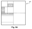
図5は、Versatile Video Codingの木構造における1以上のサブ領域に領域を分割または分岐して得ることのできる分割例500を示す概略ブロック図である。分割例500に示される分割は、エンコーダ114のブロック分割部310によって行うことができ、図3を参照して説明したように、ラグランジュ最適化によって決定されるように、符号木に従って、各CTUを1以上のCUまたはCBに分割する。
Figure 5 is a schematic block diagram illustrating an
分割例500は、正方形領域が、他の、おそらくは非正方形のサブ領域に分割された場合を示しているが、図500は分割の可能性を示すものであって、包含する領域が正方形である必要はないことを理解されたい。包含する領域が非正方形の場合、分割の結果として生じるブロックの寸法は、包含するブロックのアスペクト比に従ってスケーリングされる。領域がそれ以上分割されなくなると、つまり符号木の葉ノードでは、CUはその領域を占有する。ブロック分割部310によるCTUの1以上のCUへの特定の細分化は、CTUの「符号木」と呼ばれる。
Although partition example 500 illustrates a square region being partitioned into other, possibly non-square, sub-regions, it should be understood that diagram 500 illustrates a possible partition and that the containing region need not be square. If the containing region is non-square, the dimensions of the resulting blocks are scaled according to the aspect ratio of the containing block. Once a region is no longer partitioned, i.e., at a leaf node of the coding tree, a CU occupies the region. The particular subdivision of a CTU by
領域をサブ領域に細分化する処理は、結果として生じるサブ領域が最小CUサイズに達したときに終了しなければならない。所定の最小サイズ、例えば16個のサンプルよりも小さいブロック領域を禁止するようにCUを制限することに加えて、CUは最小の幅または高さとして4を持つように制限される。幅及び高さの観点から、または幅または高さの観点から、他の最小値にすることも可能である。細分化の処理は、最も深いレベルへの分解前に終了することもあり、その結果、CUが最小CUサイズよりも大きくなることがある。分割が発生せず、単一のCUがCTU全体を占める可能性もある。CTU全体を占める単一のCUは、利用可能な最大の符号化ユニットのサイズである。4:2:0などのサブサンプリングされたクロマフォーマットを使用しているため、ビデオエンコーダ114とビデオデコーダ134の構成により、ルマチャネルよりも早くクロマチャネルの領域の分割が終了する場合がある。
The process of subdividing a region into subregions must end when the resulting subregion reaches the minimum CU size. In addition to restricting the CU to prohibit block regions smaller than a certain minimum size, e.g., 16 samples, the CU is restricted to have a minimum width or height of 4. Other minimums are possible, either in terms of width and height or in terms of width or height. The process of subdivision may end before the deepest level of decomposition, resulting in a CU larger than the minimum CU size. It is also possible that no splitting occurs and a single CU occupies the entire CTU. A single CU occupying the entire CTU is the size of the largest coding unit available. Due to the use of subsampled chroma formats such as 4:2:0, the configuration of the
符号木の葉ノードには、更に細分化することができないCUが存在する。例えば、葉ノード510は、1つのCUを含む。符号木の非葉ノードでは、更に2つ以上のノードに分割し、各ノードは、1つのCUを形成する葉ノード、またはより小さな領域へのさらなる分割を含む非葉ノードである可能性がある。符号木の各葉ノードには、カラーチャネル毎に1つの符号化ブロックが存在する。ルマとクロマの両方で同じ深さで分割が終了すると、同じ位置にある3つのCBが生成される。ルマがクロマよりも深い深さで分割が終了すると、複数のルマCBがクロマチャネルのCBと同じ位置になる。
At the leaf nodes of the coding tree, there are CUs that cannot be further subdivided. For example,
四分木分割512は、図5に示すように、包含する領域を4つの等しいサイズの領域に分割する。HEVCと比較して、Versatile Video Coding(VVC)は、水平2値分割514と垂直2値分割516を含む更なる柔軟性を達成する。分割514及び516はそれぞれ、包含する領域を2つの等しいサイズの領域に分割する。分割は、包含するブロック内において水平境界(514)または垂直境界(516)のいずれかに沿っている。
水平三分割518及び垂直三分割520を追加することにより、Versatile Video Codingにおいてさらなる柔軟性が達成される。三分割518及び520は、包含する領域の幅または高さの1/4及び3/4に沿って、ブロックを水平方向(518)または垂直方向(520)のいずれかに3つの領域に分割する。四分木、二分木、及び三分木の組み合わせは、「QTBTTT」と呼ばれる。木の根は、0個以上の四分木分割(木の「QT」セクション)を含む。QTセクションが終了すると、0個以上の二分割または三分割が発生し(「多分木」または木の「MT」セクション)、最終的に木構造の葉ノードにおけるCBまたはCUで終了する。木がすべてのカラーチャネルを表す場合、木の葉ノードはCUとなる。木がルマチャネルまたはクロマチャネルを表す場合、木の葉ノードはCBとなる。
Further flexibility is achieved in Versatile Video Coding by adding a horizontal
四分木のみをサポートし、結果、平方ブロックのみをサポートするHEVCと比較して、QTBTTTは、特に二分木及び/または三分木分割の可能な再帰的適用を考慮することで、より多くのCUサイズが可能となる。分割の選択肢を制限することによって、ブロックサイズが異常(正方形でない)となる可能性を低減することができ、ブロック幅または高さが4未満のサンプル、または、4の倍数とならないサンプルへの分割を排除することができる。一般的に、ルマサンプルにを考慮することで制限が適用される。しかしながら、記載された構成では、制限はクロマチャネルのブロックに別に適用することができる。クロマチャネルに対して分割の選択肢の制限を適用すること、例えば、フレームデータが4:2:0のクロマフォーマットまたは4:2:2のクロマフォーマットの場合、ルマ対クロマで最小ブロックサイズが異なるものとなる可能性がある。各分割は、包含する領域に対して、辺の寸法が、変化無し、半分または1/4のサブ領域を生成する。そして、CTUサイズが2のべき乗倍であるため、全てのCUの辺の寸法も2のべき乗倍となる。 Compared to HEVC, which only supports quad-trees and, as a result, square blocks, QTBTTT allows for more CU sizes, especially by considering possible recursive application of binary and/or ternary tree partitioning. By limiting the partitioning options, the possibility of abnormal block sizes (non-square) can be reduced, and partitioning into samples with block width or height less than 4 or not a multiple of 4 can be eliminated. In general, the restrictions are applied by considering luma samples. However, in the described configuration, the restrictions can be applied separately to blocks of chroma channels. Applying the partitioning option restrictions to chroma channels, for example, when the frame data is in 4:2:0 chroma format or 4:2:2 chroma format, the minimum block size can be different for luma vs. chroma. Each partition generates a sub-region with unchanged, half, or quarter side dimensions relative to the containing region. And, because the CTU size is a power of 2, the side dimensions of all CUs are also a power of 2.
図6は、Versatile Video Codingで使用されるQTBTTT(または「符号木」)構造のデータフロー600を示す概略フロー図である。QTBTTT構造は各CTUに使用され、CTUを分割して1以上のCUとすることを定義する。各CTUのQTBTTT構造は、ビデオエンコーダ114のブロック分割部310によって決定され、ビットストリーム115に符号化されるか、またはビデオデコーダ134のエントロピーデコーダ420によってビットストリーム133から復号される。データフロー600は、図5に示される分割状態に従って、CTUを1以上のCUに分割するためにブロック分割部310が利用可能な、許容することのできる組み合わせをさらに特徴付ける。
Figure 6 is a schematic flow diagram showing a
階層の最上位レベル、すなわちCTUから始めて、0以上の四分木分割が最初に実行される。具体的には、四分木(QT)分割判定610は、ブロック分割部310によって行われる。「1」シンボルを返す610での決定は、四分木分割512に従って、現ノードを4つのサブノードに分割する決定を示す。その結果、620におけるように、4つの新しいノードが生成され、そして、新しいノードそれぞれについて、QT分割決定610への再帰が行われる。新しいノードはそれぞれ、ラスタ(またはZスキャン)順で考慮される。あるいは、QT分割判定610が、それ以上の分割が実行されない(「0」シンボルを返す)ことを示す場合、四分木分割は停止し、続いて多分木(MT)分割が考慮される。
Starting from the top level of the hierarchy, i.e., CTU, zero or more quadtree splits are first performed. Specifically, a quadtree (QT)
まず、MT分割判定612が、ブロック分割部310によって行われる。612では、MT分割を実行する判定が示されている。判定612で「0」シンボルを返すことは、ノードをサブノードにこれ以上分割しないことを示す。ノードの更なる分割が実行されない場合、そのノードは符号木の葉ノードであり、CUに対応する。葉ノードは622で出力される。あるいは、MT分割612で、MT分割を実行する決定を示す(「1」シンボルを返す)場合、ブロック分割部310は方向判定614に進む。
First, an
方向判定614では、MT分割の方向を水平(「H」または「0」)または垂直(「V」または「1」)として示す。判定614で水平方向を示す「0」が返された場合、ブロック分割部310は判定616に進む。判定614で垂直方向を示す「1」が返された場合、ブロック分割部310は判定618に進む。
判定616及び618のそれぞれにおいて、MT分割のための分割数は、BT/TT分割における2(二分割または「BT」ノード)または3(三分割または「TT」)のいずれかとして示される。すなわち、614から示された方向が水平の場合、BT/TT分割判定616はブロック分割部310によって行われ、614から示された方向が垂直の場合、BT/TT分割判定618がブロック分割部310によって行われる。
In each of
BT/TT分割判定616は、水平分割が、「0」を返すことによって示される二分割514であるか、または「1」を返すことによって示される三分割518であるかを示す。BT/TT分割判定616が二分割を示す場合、HBT CTUノード生成ステップ625において、水平二分割514に従って、ブロック分割部310により2つのノードが生成される。BT/TT分割616が三分割を示す場合、HTT CTUノード生成ステップ626において、水平三分割518に従って、ブロック分割部310により3つのノードが生成される。
The BT/
BT/TT分割判定618は、垂直分割が「0」を返すことによって示される二分割516であるか、または「1」を返すことによって示される三分割520であるかを示す。BT/TT分割618が二分割を示す場合、VBT CTUノード生成ステップ627において、垂直二分割516に従って、ブロック分割部310により2つのノードが生成される。BT/TT分割618が三分割を示す場合、VTT CTUノード生成ステップ628において、垂直三分割520に従って、ブロック分割部310により3つのノードが生成される。ステップ625~628で生じる各ノードについて、方向614に従って、左から右、上から下への順序で、MT分割決定612に戻るデータフロー600が繰り返し行われる。結果として、二分木分割及び三分木分割を適用して、様々なサイズのCUを生成することができる。
BT/
図7A及び図7Bは、CTU710から多数のCUまたはCBへのの分割例700を示す。CU712の例を図7Aに示す。図7Aは、CTU710内のCUの空間配置を示す。また、分割例700を、図7Bにおいて符号木720として示す。
Figures 7A and 7B show an
図7AのCTU710の各非葉ノード、例えば、ノード714、716、718では、含まれているノード(さらに分割されるかまたはCU)を、符号木720の列に示すようなノードのリストを生成するために、「Z順」にスキャンまたは精査する。四分木分割では、Z順スキャンの結果、左上から右の後、左下から右となる。水平方向の分割と垂直方向の分割の場合、Z順スキャン(精査)は、それぞれ、上から下へのスキャン及び左から右へのスキャンに単純化される。図7Bの符号木720は、適用されたスキャン順序に従って全てのノード及びCUをリスト化する。各分割により、葉ノード(CU)に達するまで、次の木のレベルで、2つ、3つ、または4つの新しいノードのリストが生成される。
For each non-leaf node of the
ブロック分割部310によって、画像を分解し、最終的にCUまで分割し、図3を参照して説明したように、CUを用いて各残差ブロック(324)を生成すると、残差ブロックはビデオエンコーダ114による順方向変換及び量子化の対象となる。結果として生じるTB336は、順番にスキャンされて、エントロピー符号化モジュール338の動作の一部として、残差係数の順次リストが形成される。ビットストリーム133からTBを得るために、同様の処理が、ビデオエンコーダ114によって行われる。
Once the
CPUをCUに分割した結果、小さいサイズのCU(例えば、4×4、4×8、または8×4)はフレーム内で空間的に隣接しているように見える。さらに、符号木の階層的Z順スキャンの利点として、小さいサイズのCUは時間的に続けて処理される。特に、8×8領域の四分木割分割により4つの一連の4×4CUが得られ、8×4または4×8領域の二分割により、一対の4×4CUが得られ、8×8領域の二分割により、一対の4×8領域または一対の8×4領域が得られる。得られた各領域(4×8または8×4のサイズ)は、CUを形成するか、または4×4CUに更に分割することができる。64のサンプルの領域に三分割を適用すると、サイズ16、32、及び16、すなわち、4×4、4×8または8×4、及び4×4の3つの領域が生成される。128のサンプルの領域に三分割を適用すると、サイズ32、64、32、例えば、4×8、8×8、4×8の3つの領域が生成される。小さいブロック(例えば4×4、4×8、8×4)は、64または128のようなサイズの領域を分割した結果であるので、空間的にも、CTUのZ順スキャンにおいても、一緒に見られる。 As a result of the division of the CPU into CUs, small CUs (e.g., 4x4, 4x8, or 8x4) appear spatially adjacent in the frame. Moreover, as an advantage of the hierarchical Z-order scan of the code tree, small CUs are processed consecutively in time. In particular, quadtree division of an 8x8 region results in a series of four 4x4 CUs, bisection of an 8x4 or 4x8 region results in a pair of 4x4 CUs, and bisection of an 8x8 region results in a pair of 4x8 regions or a pair of 8x4 regions. Each resulting region (of size 4x8 or 8x4) can form a CU or be further divided into 4x4 CUs. Applying trisection to the region of 64 samples produces three regions of size 16, 32, and 16, i.e., 4x4, 4x8 or 8x4, and 4x4. Applying trisection to a region of 128 samples produces three regions of size 32, 64, 32, e.g. 4x8, 8x8, 4x8. The smaller blocks (e.g. 4x4, 4x8, 8x4) are the result of dividing regions of size like 64 or 128, so they are seen together both spatially and in the Z-order scan of the CTU.
図8は、ビデオエンコーダ114及びビデオデコーダ134それぞれの行列イントラ予測モジュール390及び482の動作を、8×8ブロックを使用して、詳細に示すデータフロー800である。行列イントラ予測は、図8の例ではルマチャネルでのみ実行され、4:2:0や4:2:2などのクロマフォーマットを使用することにより生じる異なるブロックサイズを考慮する必要はない。モジュール390及び482は、それぞれ393または483のような行列予測サンプルのブロックを出力する。モードセレクタ386がCUに対して行列イントラ予測を選択したときに、ブロック393は、ビデオエンコーダ114においてPB320として用いられる。ビットストリーム133からのCUの予測モードを復号することによって、行列イントラ予測の使用が示された場合、ブロック483は、PB483として用いられる。
8 is a
モジュール390及び482の動作は、3つのステップを含む:1.平均化、2.行列乗算及びオフセット(バイアス)加算、3.双線形補間である。双線形補間は、CUのサイズが4×4より大きい場合にのみ行われる。平均化ステップは以下のように動作する。参照サンプル802(例えば358または464)がデータフロー800で受信され、上サンプル822及び左サンプル820として割り当てられる。ルマCBの幅及び高さが4より大きい場合、上サンプル822は4つのセットに分割される(図8の8×8ブロックの例における4対)。4つのセットそれぞれのコンテンツの値は平均されて、4つのフィルタ処理された上サンプル826が生成される。同様に、左サンプル820は4つのセット(図8の8×8ブロックの例における4対)に分割される。4つのセットそれぞれのコンテンツの値は平均されて、4つのフィルタ処理された左サンプル824が生成される。従って、合計8つのフィルタ処理されたサンプルが行列乗算モジュール828への入力となる。
The operation of
ブロックの幅及び高さが4に等しい場合(図8に示されるように8ではなく)、4つの上サンプル822は2対に分割され、それぞれが平均化されてフィルタ処理された2つの上サンプル826が生成される。同様に、4つの左サンプル820は2対に分割され、それぞれが平均化されてフィルタ処理された2つの左サンプル824が生成され、合計4つのフィルタ処理されたサンプルが行列乗算モジュール828への入力となる。
If the block width and height are equal to four (instead of eight as shown in FIG. 8), the four
第2のステップ(行列乗算)において、受信された行列係数(363または481)が行列イントラ予測モード(388または458)に従って選択され、行列乗算モジュール828にも入力される。また、行列乗算モジュールには、オフセット値またはバイアス値のセットも入力される。オフセットまたはバイアス値は、行列乗算の結果に加算されることで、任意のDCシフトが含まれるようになる。行列係数とバイアス値は予め決定されている。言い換えると、行列係数とバイアス値は「オフライン」トレーニングプロセスの結果であり、ビデオエンコーダ114とビデオデコーダ134にとって定数値と見なされる。
In the second step (matrix multiplication), the received matrix coefficients (363 or 481) are selected according to the matrix intra-prediction mode (388 or 458) and are also input to the
4×4CBの場合、18セットの行列係数とバイアス値(セットA)を備えた35のMIPモードが利用可能である。4×8、8×4、8×8CBの場合、10セットの行列係数とバイアス値(セットB)を備えた19のMIPモードが利用可能である。他のCBサイズの場合、6セットの行列係数とバイアス値(セットC)を備えた11のMIPモードが利用可能である。与えられた行列係数とバイアス値のセットは、2つのMIPモードに使用され得る。一方のMIPモードは提供された値を使用し、他方のMIPモードは提供された値の転置行列を使用する。さらに、ある場合には、行列係数とバイアス値のセットが1つのMIPモード専用となる。3つのケースはそれぞれ、セットA~Cのそれぞれに適用される。セットA~Cのサイズは以下に示す通りであり、また、セットA~Cのそれぞれに与えられた1つのPBの生成(つまり、1つのCUに対するMIPモードの適用)に使用するための、362または481によって選択されたワード数も示す。
セットA:サイズ16×4の18個の行列、サイズ16の18個のオフセットベクトル。CBのために選択された値のサイズは、16×4+16=80ワード。
セットB:サイズ16×8の10個の行列、サイズ16の10個のオフセットベクトル。CBのために選択された値のサイズは、16×8+16=144ワード。
セットC:サイズ64×8の6個の行列、サイズ64の10個のオフセットベクトル。CBのために選択された値のサイズは、64×8+64=576ワード。
For 4x4 CB, 35 MIP modes with 18 sets of matrix coefficients and bias values (set A) are available. For 4x8, 8x4, and 8x8 CB, 19 MIP modes with 10 sets of matrix coefficients and bias values (set B) are available. For other CB sizes, 11 MIP modes with 6 sets of matrix coefficients and bias values (set C) are available. A given set of matrix coefficients and bias values can be used for two MIP modes. One MIP mode uses the provided values and the other MIP mode uses the transpose of the provided values. Furthermore, in some cases, a set of matrix coefficients and bias values is dedicated to one MIP mode. Each of the three cases applies to each of sets A to C. The sizes of sets A to C are as follows, along with the number of words selected by 362 or 481 to be used to generate one PB (i.e., apply the MIP mode to one CU) given each of sets A to C.
Set A: 18 matrices of size 16x4, 18 offset vectors of size 16. The size of the values chosen for CB is 16x4+16=80 words.
Set B: 10 matrices of size 16x8, 10 offset vectors of size 16. The size of the values selected for CB is 16x8+16=144 words.
Set C: 6 matrices of size 64x8, 10 offset vectors of size 64. The size of the values chosen for CB is 64x8+64=576 words.
ビデオエンコーダ114及びビデオデコーダ134は、フレームサイズ及びフレームレートによって決まるピクセルレートでビデオデータを処理する。さらに、ルマCBのサイズは、幅と高さが4の倍数である。従って、セットA~Cためのメモリ帯域幅要件は、4×4のルマサンプルへのアクセスにより表現することができる。各CUに対するMIPモードの使用に制約がない場合の、各セットに対する、最悪の場合のセットA~Cそれぞれ、つまり最小ブロックサイズの各セットへのアクセス密度は次の通りである。
セットA:4×4CBは、4×4サンプル領域あたり80ワード必要。
セットB:4×8及び8×4CBは、4×4サンプル領域あたり144÷2=72ワード必要、8×8CBは、4×4サンプル領域あたり144÷4=36ワード必要。
セットC:8×16及び16×8CBは、4×4サンプル領域あたり576÷8=72ワード必要、8×32、16×16、32×8CBは、4×4サンプル領域あたり576÷16=36ワード必要、更に大きいサイズのCBは、4×4サンプル領域あたりより少ないワードが必要。
The
Set A: 4x4 CB requires 80 words per 4x4 sample region.
Set B: 4x8 and 8x4 CB require 144÷2=72 words per 4x4 sample region, 8x8 CB requires 144÷4=36 words per 4x4 sample region.
Set C: 8x16 and 16x8 CBs require 576÷8=72 words per 4x4 sample region, 8x32, 16x16, 32x8 CBs require 576÷16=36 words per 4x4 sample region, larger size CBs require fewer words per 4x4 sample region.
上記のアクセス密度によって示されるように、MIPモードの使用に制約がない場合、最悪の場合、すべてのCBがMIPモードを使用する可能性があり、符号木は、各CTUを、最悪の場合の係数メモリ(486、392)帯域幅を示すために上記で使用された小さなCBサイズに分解する可能性がある。行列係数とバイアス値の名目上のワードサイズは16ビットであるが、より少ないビット、例えば10ビットで十分な場合がある。グループ単位でのワードの取り出しは、実施可能な選択肢の1つである。しかしながら、メモリ帯域幅の負担はやや高いまま残る。 As shown by the access density above, if there are no constraints on the use of MIP mode, in the worst case, all CBs may use MIP mode, and the code tree may decompose each CTU into small CB sizes, which were used above to indicate the worst case coefficient memory (486, 392) bandwidth. The nominal word size of the matrix coefficients and bias values is 16 bits, but fewer bits, e.g. 10 bits, may be sufficient. Fetching words in groups is one possible option. However, the memory bandwidth burden remains rather high.
MIPモード選択の統計値によれば、典型的には、(JVET common test conitions文書JVETーN1010で定義されるように)広いテストセットの場合の20%において、上と左のブロックを考慮した場合、隣接して配置されたCBに対してMIPモードが選択される。従って、MIPモードの適用頻度を制限することにより、MIPモードの利用可能性の観点から、圧縮効率ゲインの相応の低下を引き起こすことなく、係数メモリ486及び392に必要な最悪の場合のメモリ帯域幅を軽減することが可能である。MIPモードの選択に関する制約については、図11~図16を参照して説明する。
Statistics for MIP mode selection show that typically in 20% of cases for a wide test set (as defined in JVET common test conditions document JVET-N1010), MIP mode is selected for adjacently located CBs when considering the top and left blocks. Thus, by limiting the frequency of MIP mode application, it is possible to reduce the worst-case memory bandwidth required for
行列乗算モジュール828は、行列係数のセット(363または481)及びフィルタ処理された参照サンプル(すなわち、824及び826)を使用して行列乗算を実行する。バイアス値が行列乗算の出力に加算されて、疎ブロック830が形成される。疎ブロック830は、部分的に393または483を埋める、網掛けされたサンプルとして表されている。393または483の残りのサンプルは、上参照サンプル822とフィルタ処理された左参照サンプル824、または左参照サンプル820とフィルタ処理された上サンプル822のいずれかからの寄与により(図8に示されるように)、双線形補間を用いて導出される。
The
図9Aは、CTU900の一例を示す。CTU900は、MIPモードのメモリアクセス帯域幅が適用される領域を有する。行列イントラ予測は、VPDUサイズの領域、つまり128×128のCPU900の64×64の象限内で適用される。例えば、割当量が適用される512のルマサンプル領域は、(i)32×16の領域912、(ii)16×32の領域914、及び(iii)64×8の領域916を含む。領域912は、更に、様々なCU、すなわち、図9Bの912a~912hに分解される。図9Bの例では、CU912aのサイズは16×4であるため、セットCに属し、CU912dのサイズは8×8であるため、セットBに属し、同様に9112b、912c及び912e(すべてサイズ8×4)もセットBに属する。CU912f及びCU912gは、それぞれ4×4であり、セットAに属する。図11から図16を参照して説明するように、512のルマサンプルの領域の面積は、MIPモードに制約を適用するかどうかを決定するための閾値として記載された構成で使用することができる。上記のセットAからCは通常、領域の分割から生じるため、512のサンプルの領域の面積を使用することは制約として適している。しかしながら、閾値は、以下に説明するように、異なる面積に関連し得る。
9A shows an example of a
図10は、図9AのCTU900の例に対応する符号木10を示している。領域912は、領域914及び916と同様に、含まれるCUに対する割当量がMIP行列係数の読み取りのために確立されている符号木のノードに対応する。領域における1以上のCUへの分解は、簡略化のために不図示とする。MIPモードを使用するように構成された各CUについて、セットA~Cの1つにマッピングするCUサイズに応じた割当量は、図11乃至図16を参照して以下に説明するように、領域(すなわち、912、914、916)の割当量から差し引かれる。
Figure 10 shows a code tree 10 corresponding to the
図11は、画像フレームの符号化ユニットをビデオビットストリーム115に符号化するための方法1100を示している。方法1100は、構成されたFPGA、ASIC、またはASSP等の装置によって具現化され得る。さらに、方法1100は、プロセッサ205の実行下でビデオエンコーダ114によって実行され得る。従って、方法1100は、コンピュータ可読記憶媒体及び/またはメモリ206に格納され得る。一連の符号化ユニットである画像フレームをビットストリーム115に符号化する方法1100の動作は、行列イントラ予測の使用に制限をかける。従って、方法1100の動作は、制限がない場合の最悪の場合の潜在的なメモリ帯域幅と比較して、行列イントラ予測で必要なメモリ帯域幅に制限をつけることになる。方法1100は、フレームをCTUに分割するステップ1110から始まる。
11 shows a
フレームをCTUに分割するステップ1110において、ブロック分割部310は、プロセッサ205の実行下で、フレームデータ113の現フレームをCTUの行列に分割する。分割の結果として生じるCTUの符号化処理を開始する。プロセッサにおける制御は、ステップ1110から符号木の決定ステップ1120に進む。
In
符号木の決定ステップ1120で、プロセッサ205の実行下で、ビデオエンコーダ114は、図5から図7を参照して説明したように、様々な分割オプションをテストすると共に、CTUの符号木に到達するための符号化ユニットの決定ステップ1130の動作が行われる。ステップ1120の動作は、図12を参照して説明する。プロセッサ205における制御は、ステップ1120から、符号化ユニットの予測モードの決定ステップ1130に進む。
In the code
符号化ユニットの決定ステップ1130において、プロセッサ205の実行下で、ビデオエンコーダ114は、選択された符号化ユニットをビットストリーム115に符号化する際に使用する予測モードを決定する。符号化ユニットは、スキャンパターンに従って選択することができる。ステップ1130の動作は、図13を参照してさらに説明する。符号化ユニットの予測モードが一旦選択されると、プロセッサ205における制御は、ステップ1130から符号化ユニットの符号化ステップ1140に進む。符号化ユニットのための予測モードの選択に際して、符号化ユニットは、符号化ユニット自体が符号木の分割の階層から生じるものであるため、所定の符号化ユニットに到達するための特定の分割の組み合わせも選択され、これにより、符号木が決定される。
In a coding
符号化ユニットの符号化ステップ1140において、エントロピーエンコーダ338は、プロセッサ205の実行下で、ステップ1130で決定された符号化ユニットをビットストリーム115に符号化する。決定された符号木は、プロセッサ205の実行下で、図5及び図6に示すように、選択された分割を示すために「分割フラグ」及び他の構文要素を使用して、エントロピーエンコーダ338によってステップ1140でビットストリーム115に効率的に符号化される。
In encoding the
ステップ1140での動作は、図14を参照してさらに説明する。プロセッサ205における制御は、ステップ1140から最終符号化ユニットテストステップ1150に進む。
The operations at
最終符号化ユニットテストステップ1150で、プロセッサ205は、現在の符号化ユニットがステップ1120の符号木における最後の符号化ユニットであるかどうかをテストする。現符号化ユニットがステップ1120の符号木における最後のものである場合(ステップ1150で「YES」)、プロセッサ205における制御は、最終CTUテストステップ1160に進む。現符号化ユニットがステップ1120の符号木における最後のものでない場合(ステップ1150で「NO」)、ステップ1120の符号木における次の符号化ユニットが、決定及び符号化のためのスキャンパターンを使用して選択され、プロセッサ205における制御は、ステップ1130に進む。従って、ステップ1130は、ステップ1120で決定された符号木から生じる各CUに対して実行される。
In a last coding
最終CTUテストステップ1160で、プロセッサ205は、現CTUがスライスまたはフレーム内の最後のCTUであるかどうかをテストする。そうでない場合(ステップ1160で「NO」)、ビデオエンコーダ114はフレーム内の次のCTUに進み、プロセッサ205における制御はステップ1160からステップ1120に戻り、フレーム内の残りのCTUの処理を継続する。CTUがフレームまたはスライスの最後のものである場合、ステップ1160は「YES」を返し、方法1100は終了する。方法1100の動作の結果、画像フレーム全体が一連のCTUとしてビットストリームに符号化される。
In a last
方法1100は、ビデオシーケンス内の各画像フレームに対して実行される。方法1100は、CTU毎にCUを決定することができる。言い換えると、CTUのCUが、まず1つのパスまたはパイプラインステージで決定され、次に、ビットストリームに符号化する第2段階が続く。方法1100はまた、CTUと比較してVPDUの面積は小さいためにメモリ消費が削減されるため、例えば、VPDU毎に、より細かくCUを決定してもよい。
図12は、ステップ1120で実施されるCTUの符号木を決定する方法1200を示す。方法1200は、CTUを受信し、評価のための候補分割及び候補符号化ユニットを生成し、ビットストリーム115に符号化される分割及び符号化ユニットを最終的に選択する。特に、方法1200は、ノード下、すなわち空間領域内で、符号化ユニットにおけるMIPモードの適用を制限する、符号木内の特定のノードまたは領域におけるMIPモードメモリ帯域幅の割当量を確立する。方法1200は、構成されたFPGA、ASIC、またはASSP等の装置によって具現化され得る。さらに、方法1200は、プロセッサ205の実行下でビデオエンコーダ114によって実行され得る。従って、方法1200は、コンピュータ可読記憶媒体及び/またはメモリ206に格納され得る。方法1200は、候補符号木内の各ノード(領域)について実施される。方法1200は、領域面積テストステップ1210で開始する。
12 shows a
領域テストステップ1210において、ビデオエンコーダ114は、プロセッサ205の実行下で、利用可能な分割オプションに従って(図5に関連して説明した分割オプションを使用して)、符号木の候補ノードによって占有される面積をテストする。説明した構成では、領域は、分割が停止する前にさらに分割し、CUが形成され得る符号木のノードに関連する。領域は、現符号化ユニットの直接の親に対応する必要はない。つまり、MIPモードのメモリアクセス帯域幅の割当量が設定された親領域は、符号木の現ノードより上の複数のノードである可能性がある。例えば、512のルマサンプルの領域は、例えば4×4、4×8、8×4等のサイズの、多数の小さな符号化ユニットに分割できる。エンコーダによる検索が進むにつれて、候補の分割から生じるさまざまな候補ノードがテストされる。各候補ノード内で、結果として得られる符号化ユニットのさまざまな予測モードがテストされる。領域が占めるルマサンプルの面積が閾値を満たさない場合、領域面積テストは、真と評価し、プロセッサ205における制御は、ステップ1210から割当量設定ステップ1220に進む。領域により占められるルマサンプルの面積が閾値を満たしている場合、領域面積テストは偽と評価され、プロセッサ205における制御は、ステップ1210から分割生成ステップ1230に進む。一実施形態では、図11から図16の例に示されるように、閾値は512サンプルであり、領域が512サンプルより大きい面積を有するときに満たされる。以下に説明するように、他の閾値を使用することもできる。閾値は、通常、エンコーダ114及びデコーダ134の必要な性能に基づいて事前に決められている。
In a
割当量設定ステップ1220において、ビデオエンコーダ114は、プロセッサ205の実行下で、符号木の現ノードの面積に対応する領域に対する割当量を設定する。この割当量は、現領域をより小さな領域に分割した結果として生じる、現領域内のすべてのサブノード(サブ領域)で使用できる。512以下のルマサンプルのすべての領域について、符号化ユニット予測モードが評価されているときに、MIPモードを適用している場合の割当量を考慮することができる。512のルマサンプルの面積は、例えば、三分割の対象となる可能性があり、その結果、面積128、256、及び128のルマサンプルの符号化ユニットが生成される。面積128のルマサンプルの符号化ユニットの寸法は、8×16または16×8である可能性があり、その場合、最悪の場合のメモリ帯域幅制限に達する可能性があり、その結果、領域内における他の符号化ユニットにMIPモードを使用できなくなり、領域が更に細分化される可能性を含む。512のルマサンプルの面積が、例えば16×16の、ルマサンプル面積が256の2つの符号化ユニットに二分割される場合、最悪の場合のメモリ帯域幅制限に到達せず、結果として得られるCUに対するMIPモードの使用に制限は生じない。ただし、サンプル面積が256の領域それぞれを、より小さなCU、つまり、サイズ16×8、8×16、8×8、8×4、4×8、及び4×4のCUにさらに分割すると、先に結果として生じたCUが割当量を消費しているために、後で結果として生じるCUのMIPモードの使用が制限される可能性がある。
In a
4×4が最小のルマ符号化ユニットのサイズであり、他のすべての符号化ユニットはこのサイズの整数倍であり、従ってすべての領域もこのサイズの複数倍であるため、割当量は4×4ブロック面積あたりの最大ワード読み出しとして表現することができる。割当量は、4×4ブロックの場合は40ワード読み出しであり、ルマサンプル面積が512の場合、512ルマサンプル領域において許可される読み出し動作の最大数として、(512÷(4×4)*40=1280ワード読み出しに対応する。CUにMIPモードを使用する度に、必要な読み取り数が割当量から差し引かれ、MIPモードをさらに使用するには割当量が不十分となると、図13及び図14に関連して説明するように、それ以上のCUはMIPモードを使用できなくなる。このようにして、より大きなサイズのCUは、MIPモードを使用することができ、例えば、面積512のサンプルの単一のCUまたは面積256のサンプルのCUのペアは、制約から制限を受けること無くMIPモードを使用することができる。符号木が面積512のサンプルを多数のより小さなCUに分解する場合、割当量が消費されることにより、領域内のそれ以上のCUによるMIPモードの使用を禁止する可能性がある。4×4あたり40ワードの割当量を有する512サンプル面積の場合、領域の合計の割当量は512÷(4×4)*40=1280ワードとなる。512サンプル面積を8×16または16×8のサイズの4つのCUに分割した場合、2つのCUでMIPモードを使用すると、CUあたり576ワード、つまり1152ワードが消費される。残りの割当量である128ワード読み出しでは、領域内の他の2つのCUがMIPモードを使用するには不十分である。プロセッサ205における制御は、ステップ1220から分割生成ステップ1230に進む。
Since 4x4 is the smallest luma coding unit size, and all other coding units are integer multiples of this size, and therefore all regions are multiples of this size, the budget can be expressed as the maximum word reads per 4x4 block area. The budget is 40 word reads for a 4x4 block, which corresponds to (512÷(4x4)*40=1280 word reads) as the maximum number of read operations allowed in a 512 luma sample area for a luma sample area of 512. Each time MIP mode is used for a CU, the required number of reads is subtracted from the budget, and when the budget is insufficient for further use of MIP mode, no more CUs can use MIP mode, as will be explained in connection with Figures 13 and 14. In this way, CUs of larger size can use MIP mode, for example a single CU of
分割生成ステップ1230において、ブロック分割部310は、プロセッサ205の実行下で、符号木における現ノードの候補分割セットを生成する。分割は図5に示す通りであり、関連する構文要素は図6に示され、図7に例示されている。「分割なし」、つまり510を生成する場合、符号化ユニットは後で生成される。他の分割タイプ、つまり512~520を生成する場合、符号木の追加のノードが各分割に従って生成される。方法1200は、方法1200が後で行われるときに「分割なし」で生成が行われた場合に、追加のノードの符号化ユニットを生成するために繰り返される。方法1200は、CTUの各ノードに対して順番に繰り返される。従って、CTUのすべての分割が決定される。また、分割内で分割の生成を繰り返し行うため、二分割、三分割、及び四分木分割を使用した再帰数を制限する可能性のある最小CUサイズ及び深さの再帰制約の制約内で、与えられたCTUにおけるすべての可能な符号化ユニットが検索される。プロセッサ205における制御は、ステップ1230からCU生成ステップ1240に進む。
In the
CU生成ステップ1240において、ブロック分割部310は、プロセッサ205の実行下で、分割生成ステップ1230で「分割なし」が生成された各場合に候補CUを生成する。ステップ1240では、候補CUの予測モードはまだ決定されておらず、最終モードはまだ選択されていないが、Z順スキャンで先行するCUの予測モードは分かっている。従って、隣接する(CU内の位置に関して)参照サンプルは、現CUを含む分割と同じ分割操作からの隣接CUから、または異なる親領域から生じる隣接領域から、または全く異なるCTUからのイントラ予測に使用することができる。ステップ1240は、符号木の領域を、図3に関連して説明したような予測ブロックを含む符号化ブロックに効率的に分割する。方法1200は、ステップ1240で終了し、プロセッサ205における制御は方法1100に戻り、生成されたCUの予測モードが決定される。
In the
図13は、ステップ1130で実施される符号化ユニットを決定するための方法1300を示す。方法1300は、方法1200を実行することによって生成される符号化ユニットの予測モードの決定を含む。予測モードは、イントラ予測、インター予測、及び現符号化ユニットを含む領域内でMIPモードを使用するための割当量に応じたMIPモードを含む。方法1200で確立した割当量は、現CUに対してMIPモードをテストするかどうかを制御するために使用される。割当量の一部は、CU内の符号語の数に応じて、領域内のCUが最悪の場合のブロックのサイズになる度に(上記のケースA~Cに関連して説明したように)消費される。割当量が一旦消費されると、領域内におけるMIPモードを潜在的に使用する可能性のある符号化ユニットはそれ以上検索されない。つまり、方法1300は、方法1300の以前の実施により、符号木の共通の親ノードに適用される設定されたメモリアクセス帯域幅の割当量を使い果たしていない場合にのみ、MIPモードのテストを実行する。
13 illustrates a
領域は、現符号化ユニットの直接の親に対応する必要はない、すなわち、MIPモードメモリアクセス帯域幅割当量が設定された親領域は、符号木の現ノードにおける現ノードより上の複数のノードであり得る。例えば、512ルマサンプルの領域は、例えば4×4、4×8、8×4等のサイズの多数の小さな符号化ユニットに分割され得る。各CUについて、MIPモードの使用は、512ルマサンプルの領域のための割当量の残りによって制限される。方法1300は、モードセレクタ386によって、または部分的にモジュール3960によって実施され得る。方法1300は、構成されたFPGA、ASIC、またはASSP等の装置によって具現化され得る。さらに、方法1300は、プロセッサ205の実行下でビデオエンコーダ114によって実行され得る。従って、方法1300は、コンピュータ可読記憶媒体及び/またはメモリ206に格納され得る。方法1300は、イントラ予測モードのテストステップ1310で開始する。
The region does not have to correspond to the direct parent of the current coding unit, i.e., the parent region for which the MIP mode memory access bandwidth quota is set may be multiple nodes above the current node in the coding tree. For example, a region of 512 luma samples may be divided into many smaller coding units of size, e.g., 4x4, 4x8, 8x4, etc. For each CU, the use of MIP mode is limited by the remainder of the quota for the region of 512 luma samples. The
イントラ予測モードのテストステップ1310において、プロセッサ205の実行下で、ビデオエンコーダ114は、現符号化ユニットを符号化する際に使用する可能性のある、「通常の」イントラ予測モード、すなわちDC、平面、及び角度イントラ予測モードをテストする。CUで使用可能なイントラ予測モードの中から最適なイントラ予測モードを選択するために、一般的に、ラグランジュ最適化が実行される。二次変換、つまり330と344の適用もテストされ、変換スキップの場合を含む異なるタイプの一次変換(DCT-2、DCT-8、DST-7)もテストされる。プロセッサ205における制御は、ステップ1310からインター予測モードのテストステップ1320に進む。
In a test intra
インター予測モードのテストステップ1320において、プロセッサ205の実行下で、ビデオエンコーダ114は、インター予測されたPUを生成するための様々な動きベクトルをテストする。インター予測の使用を評価する場合、動きベクトルは、候補の動きベクトルセットの中から選択される。候補の動きベクトルは、検索パターンに従って生成される。候補の動きベクトルのために取得された参照ブロックの歪みをテストする場合、符号木で禁止されているクロマ分割の適用が考慮される。分割がクロマで禁止され、ルマで許可されている場合、結果として得られるルマCBはインター予測を使用しても良い。動き補償は、ルマチャネルにのみ適用されるため、歪み計算では、ルマの歪みは考慮されるが、クロマの歪みは考慮されない。クロマ分割が禁止されている場合、クロマチャネルで動き補償が実行されないため、クロマ歪みは考慮されない。クロマの場合、考慮されるイントラ予測モードと符号化されたクロマTB(存在する場合)に起因する歪みが考慮される。ルマとクロマの両方を考慮する場合、インター予測検索では、最初にルマの歪みに基づいて動きベクトルを選択し、次にクロマの歪みも考慮して動きベクトルを「微調整」することができる。微調整では、通常、サブピクセル変位など、動きベクトル値の小さな変動が考慮される。特定の動きベクトルは、「マージモード」によって生成されるものであり得、それにより、現CUの動きベクトルは、隣接するCUからの動きベクトルから導出される。マージモードは、選択された「動きベクトル予測子」に関連して適用される「動きベクトルデルタ」のシグナリングを必要とする可能性がある他の動きベクトルと比較して、ビットストリーム構文により、より完結に表現される。動きベクトル予測子は、一般に、空間的または時間的に隣接するCUから導出される。イントラ符号化されたスライス、例えば、一連のフレームの最初のフレームの場合、インター予測は利用できないため、ステップ1320は実行されない。プロセッサ205における制御は、ステップ1320から割当量内テストステップ1330に進む。
In an inter prediction
割当量内テストステップ1330で、プロセッサ205の実行下で、ビデオエンコーダ114は、MIPモードメモリアクセス帯域幅割当量が現CUに適用可能であるかどうかをテストする。1330で実行されるテストは、現CUがステップ1220においてMIPモード割当量が確立された、512ルマサンプル領域内に含まれるかどうかを判定する。現CUが512ルマサンプル領域よりも大きい場合、適用される割当量の制約は無い。従って、CUは、MIPモードの使用に対する更なる制約を受けることはなく、プロセッサ205における制御は、MIPモードのテストステップ1340に進む(1330で「真」)。現CUのサイズが512ルマサンプルのサイズ以下の場合、図8を参照して説明したように、現CUでMIPモードを使用するために必要な割当量を、その領域の割当量の残りと比較する。MIPモードを現CUに適用するのに十分な割当量が無い場合、プロセッサ205における制御は、ステップ1330からモード選択ステップ1350に進む(ステップ1330で「偽」)。MIPモードを現CUに適用するのに十分な割当量がある場合(ステップ1340で「真」)、プロセッサ205における制御は、ステップ1330からステップ1340に進む。
In a test within
MIPモードのテストステップ1340において、モードセレクタ386は、さまざまなMIPモードをテストして、CUのサイズに対して利用可能なMIPモードの中から、現CUを予測するために使用する最良のMIPモードを決定する。ステップ1310におけるイントラ予測モードのテストと同様に、テストされたMIPモードの符号化コストとそれらに関連する残差に対する歪みを打ち消すために、ラグランジュ最適化を実行しても良い。プロセッサ205における制御は、ステップ1340からモード選択ステップ1350に進む。
In a MIP
モード選択ステップ1350において、プロセッサ205の実行下で、モードセレクタ386は、ステップ1310、1320、及び1350で得られた候補から、CUの最終モードを選択する。方法1300は、プロセッサ205における制御が方法1100に戻ることで終了する。
In a
図14は、ステップ1140で実施されるように、CTUの符号木の符号化ユニットをビデオビットストリーム115に符号化するための方法1400を示す。方法1400は、構成されたFPGA、ASIC、ASSP等の装置によって具現化され得る。さらに、方法1400は、プロセッサ205の実行下で、例えばエントロピーエンコーダ338等のビデオエンコーダ114によって実行することができる。従って、方法1400は、コンピュータ可読記憶媒体及び/またはメモリ206に格納され得る。方法1400は、予測モードの符号化ステップ1410で開始する。
14 shows a
予測モードの符号化ステップ1410において、ステップ1350で決定され、予測モード387によって示されるように、エントロピーエンコーダ338は、プロセッサ205の実行下で、イントラ予測(通常のイントラ予測モード使用またはMIPモード使用の両方を含む)またはインター予測のいずれかの使用を示すコンテキスト符号化ビンを使用してフラグを符号化する。ステップ1410でのフラグの符号化は、通常のイントラ予測とMIPモードとを区別しない。通常のイントラ予測とMIPイントラ予測(適用可能な場合)との区別は、MIPモードフラグ符号化ステップ1430で符号化される。プロセッサ205における制御は、ステップ1410から割当量テストステップ1420に進む。
In a prediction
割当量テストステップ1420において、プロセッサ205の実行下で、ビデオエンコーダ114は、MIPモードのメモリアクセス帯域幅割当量が現CUに適用可能であるかどうかをテストする。このテストにより、現CUが、ステップ1220でMIPモード割当量が確立された、512ルマサンプル領域に含まれるかどうかを決定する。現CUが512ルマサンプル領域よりも大きい領域に含まれる場合、適用すべき割当量の制約は無く、CUはMIPモードの使用に関してそれ以上の制約を受けない。プロセッサ205における制御は、MIPモードフラグの符号化ステップ1430に進む(1420で「TRUE」)。
In a
現CUが512ルマサンプルのサイズ以下の領域に含まれる場合、図8を参照して説明したように、現CUにMIPモードを使用するために必要な割当量を、その領域のための割当量の残りと比較する。MIPモードを現CUに適用するのに十分な割当量が無い場合、プロセッサ205における制御は、ステップ1420からTBの符号化ステップ1440に進む(ステップ1420で「FALS」)。しかしながら、MIPモードを現CUに適用するのに十分な割当量がある場合(1420で「TRUE」)、現CUが512サンプル以下の領域にある場合でも、プロセッサ205における制御はステップ1420からステップ1430に進む。ステップ1420の動作は、ステップ1330の動作に対応し、従って、MIPフラグのみが、方法1300でMIPモードが検索されたCUについて、方法1400で符号化される。
If the current CU is in a region of 512 luma samples or less in size, the budget required to use MIP mode for the current CU is compared with the remaining budget for that region, as described with reference to FIG. 8. If there is not enough budget to apply MIP mode to the current CU, control in the
MIPモードフラグの符号化ステップ1430において、エントロピーエンコーダ338は、プロセッサ205の実行下で、ステップ1350で決定されたように、MIPモードか否かの選択を示すコンテキスト符号化されたビンをビットストリーム115に符号化する。ビンを符号化するために使用するコンテキストは、ステップ1420を参照して説明する。MIPモードが選択された場合、エントロピーエンコーダ338は、どの特定のMIPモードがビットストリーム338への符号化に使用されたかの選択も符号化する。MIPモードは、「最も可能性の高いモード」と残りのモードの間の選択を使用する代わりに、短縮された二値符号語を使用して符号化してもよい。短縮された二値符号語を使用することで、最も可能性の高いモードが隣接する角度イントラ予測されたCUから導出された潜在的なテーブルルックアップを含む、最も可能性の高いモードのリストを導出する必要が無くなる。プロセッサ205における制御は、ステップ1430からTBの符号化ステップ1440に進む。
In a
TBの符号化ステップ1440において、エントロピーエンコーダ338は、プロセッサ205の実行下で、現CUに関連するTBの残差係数をビットストリームに符号化する。一般に、各TBのフラグは、少なくとも1つの有意係数の存在を示し、係数は、最後の有意係数位置からDC(左上端)係数位置に戻るスキャンパターンに従って1つずつ符号化される。これにより方法1400は終了し、プロセッサ205における制御は方法1100に戻る。
In a
図15は、ビデオビットストリーム133から画像フレームの符号化ユニット及び変換ブロックを復号する方法1500を示す。方法1500は、構成されたFPGA、ASIC、またはASSP等の装置によって具現化され得る。さらに、方法1500は、プロセッサ205の実行下で、ビデオデコーダ134によって実行され得る。従って、方法1500は、コンピュータ可読記憶媒体及び/またはメモリ206に格納され得る。方法1500は、フレームをCTUに分割するステップ1510で開始する。
15 shows a
フレームをCTUに分割するステップ1510で、ビデオデコーダ134は、プロセッサ205の実行下で、フレームデータ133(復号予定)の現フレームをCTUの行列に分割する。分割の結果として生じるCTUの復号が始まる。プロセッサ205における制御は、ステップ1510から符号化ユニットの復号ステップ1520に進む。
In
符号化ユニットの復号ステップ1520で、エントロピーデコーダ420は、プロセッサ205の実行下で、図5から図7を参照して説明したように、符号木に従ってビットストリーム133から分割フラグを復号する。分割フラグを復号することにより、ステップ1520は、CTU内、すなわち、CTUの符号木に従って、CUのサイズ及び位置を決定する動作を行うことができる。方法1300の進行は、ステップ1520への反復を含み、その結果、CTUの符号木全体を精査することになり、各CUが復号される。プロセッサ205における制御は、ステップ1520から符号化ユニットの復号ステップ1530に進む。
In a coding
符号化ユニットの復号ステップ1530において、エントロピーデコーダ420は、プロセッサ205の実行下で、ビットストリーム133から符号化ユニットを復号する。ステップ1530は、以下に図16に関連して説明する方法1600を呼び出して、CUを復号する。プロセッサ205における制御は、ステップ1530から最終符号化ユニットのテストステップ1540に進む。
In a decoding
最終符号化ユニットのテストステップ1540で、プロセッサ205は、ステップ1520で分割フラグを復号することから決定されるように、現符号化ユニットがCTUの最後の符号化ユニットであるかどうかをテストする。現符号化ユニットがCTUの最後の符号化ユニットである場合(ステップ1540で「YES」)、プロセッサにおける制御は、最終CTUテストステップ1550に進む。現在の符号化ユニットがステップ1520の符号木における最後の符号化ユニットでない場合(ステップ1540で「NO」)、ステップ1520の符号木における次の符号化ユニットを復号するために選択し、プロセッサ205における制御は、ステップ1520に進む。
In a last coding
最終CTUテストステップ1550で、プロセッサ205は、現CTUがスライスまたはフレーム内の最後のCTUであるかどうかをテストする。現CUが最後のCUではない場合(ステップ1550で「NO」)、ビデオデコーダ134は、フレームまたはスライス内の次のCTUに進み、フレーム内の残りのCTUの処理を続行するために、プロセッサ205における制御はステップ1550からステップ1520に戻る。CTUがフレームまたはスライスの最後のCTUである場合、ステップ1550は「YES」を返し、方法1500は終了する。方法1500の結果として、ビットストリームから画像フレーム全体が一連のCTUとして復号される。
In a last
図16は、ステップ1530で実施される、ビデオビットストリーム133から符号化ユニットを復号する方法1600を示す。方法1600は、構成されたFPGA、ASIC、またはASSP等の装置によって具現化され得る。さらに、方法1600は、プロセッサ205の実行下で、ビデオデコーダ134によって実行され得る。従って、方法1600は、コンピュータ可読記憶媒体上及び/またはメモリ206内に格納され得る。方法1600は、pred_modeフラグの復号ステップ1602で開始する。
16 shows a
pred_modeフラグの復号ステップ1602において、エントロピーデコーダ420は、コンテキスト符号化されたビンを復号して、現符号化ユニットがインター予測またはイントラ予測(MIPモードを含む)を使用するかを決定する。プロセッサ205における制御は、ステップ1602からインター予測テストステップ1604に続く。ステップ1604では、pred_modeフラグからインター予測が使用されたかどうかを決定する。現在の符号化ユニットがインター予測を使用する場合(インター予測テストステップ1604で「TRUE」)、プロセッサ205における制御は、ステップ1602からインター予測の実行ステップ1606に続く。ステップ1606でインター予測が実行され、その結果、参照ブロック(434)が取り込まれると共に、フィルタ処理してPUを生成し、続いて各カラーチャネルのTBを復号し、TB(1690)をPUに加算してCUを復号する。プロセッサ205における制御は、ステップ1606からTBの加算ステップ1690に続く。
In a pred_mode
現符号化ユニットがイントラ予測またはMIPモードを使用する場合(ステップ1604で「FALSE」)、プロセッサ205における制御は、MIPモード割当量テストステップ1610に続く。MIPモード割当量テストステップ1610では、割当量に応じて、現CUでMIPモードが利用できるかどうかを決定する。割当量は、ステップ1330または1420を参照して説明した割当量に対応する。説明した例では、現CUを含む領域が面積の閾値(512ルマサンプル)よりも大きい場合、適用可能な割当量の制約はなく、MIPモードを使用できる(ステップ1610でTRUE)。プロセッサ205における制御は、ステップ1610からMIPモードフラグの復号ステップ1620に進む。
If the current coding unit uses intra prediction or MIP mode (
ステップ1610で、現CUを含む領域の面積が閾値以下(512ルマサンプル)である場合、図8を参照して説明したように、現CUにMIPモードを使用するために必要な割当量を、その領域の割当量の残りと比較する。現CUにMIPモードを適用するのに十分な割当量がある場合、MIPモードが利用可能であり(ステップ1610で「TRUE」)、方法1600はステップ1620に進む。割当量が不十分な場合、現CUではMIPモードを利用できない(MIPモード割当量テストステップ1610で「FALSE」)。そして、プロセッサ205における制御は、イントラ予測モードの復号ステップ1612に進む。
In
ステップ1612では、イントラ予測モードの復号から始めて、通常のイントラ予測(DC、平面または角度)が使用される。プロセッサ205における制御は、ステップ1612からイントラ予測の実行ステップ1614に進む。そして、ステップ1614では、イントラ予測を実行する。プロセッサ205における制御は、ステップ1614からTBの加算ステップ1690に進む。
Starting with decoding the intra prediction mode in
ステップ1620の実行に際して、MIPフラグは、単一のコンテキストコード化されたビンを使用して、エントロピーデコーダ420によって復号される。ビンは1つのコンテキストを使用するため、例えば、隣接するCUのMIPモードの使用や、1つのビンを復号するための複数の可能なコンテキストから1つのコンテキストを選択するために使用され得るブロックサイズやその他のパラメータに応じて、コンテキストを選択する必要は無い。プロセッサにおける制御は、ステップ1620から、MIPモードが選択されたかをテストするステップ1630に進む。
In performing
ステップ1630では、MIPモードが選択されているかどうかを決定する。復号されたMIPモードフラグがMIPモードが使用されていないことを示す場合(MIPモードが選択されたかをテストするステップ1630で「FALSE」)、制御はステップ1612に進んで、通常のイントラ予測モードの1つを使用してブロックを復号する。復号されたMIPモードフラグが、CUにMIPモードが使用されていることを示す場合(ステップ1630で「TRUE」)、プロセッサ205における制御は、MIPモードの復号ステップ1640に進む。
In
MIPモードは、ステップ1640を実行する際にビットストリーム133から復号される。プロセッサ205における制御は、ステップ1640から行列係数の読み出しステップ1650に進む。復号されたMIPモードは、ステップ1650において、行列係数481のセットを行列係数メモリ486から読み出すために使用される。割当量に使用に応じてステップ1610でのMIPモードの使用を制限することにより、行列係数メモリ486がマトリックス係数481を供給するために必要な最大メモリ帯域幅消費が低減される。
The MIP mode is decoded from the
方法1600は、ステップ1650から隣接するサンプルのフィルタ処理ステップ1660に遷移する。隣接する参照サンプル464は、ステップ1660でフィルタ処理される。方法1600は、ステップ1660から行列乗算ステップ1670に遷移する。ステップ1600は、モジュール482が、例えば、行列係数481及びサンプル464を使用することで実施することができる。フィルタ処理された参照サンプル及び行列係数481は、図8の例828と同様に、ステップ1670で乗算される。
The
方法1600は、ステップ1670からPBの補間ステップ1680に遷移する。ステップ1670の実行により決定された疎ブロック(すなわち、830)は、ステップ1680での補間処理によりPB(すなわち483)を埋めるために使用される。方法1600は、ステップ1680のPBの補間ステップからTBの加算ステップ1690に遷移する。復号された残差は、TBを生成するために使用され、生成されたTBは、CUを復号するためにステップ1690においてPB483に加算される。符号化ユニットは、ステップ1690で生成された予測ブロックを用いて復号される。方法1600は、ステップ1690の完了時に終了する。
The
方法1600を実行する際に、ビデオデコーダ134は、行列係数を取り出すための最悪の場合のメモリ帯域幅に制約を伴う行列イントラ予測のサポートを達成する。ここで説明した制約は、使用制限が有効になっていない場合と比較して、エラーに影響を与えるという点においてMIPモードの選択を過度に制限するものではない。選択を過度に制限しない動作は、一般にMIPモードで符号化されたCUのうち、ほんの20%が、同じくMIPモードを使用する左または上のCUに隣接している、という決定された統計的な見込みに基づいている。メモリアクセス割当量を確立するための細かさとして使用される領域よりも大きい領域間の境界、つまり、512ルマサンプルと、20%の見つかったものの測定に含まれるCTU間の境界。
In performing the
図11から図16の実施例では、制約に基づいてMIPモードが使用されるかどうかを示す。制約は、例えば図12において、現CUの領域の面積が閾値面積を満たすかどうかに応じて決まる、現CUの領域の面積及び行列イントラ予測フラグが符号化または復号されるか、に基づいて、実施される。説明した実施では、ステップ1330、1420、1610に関連して説明したように、行列イントラ予測フラグが符号化されるかどうかは、領域が閾値を満たしている場合には領域の面積に応じて、(ii)領域の面積が閾値を満たしていない場合には領域の割当量に応じて決まる。従って、行列イントラ予測フラグが符号化(または復号)されるかどうかは、少なくとも領域の面積が閾値面積を満たすかどうかによって決まる。
11 to 16 show whether the MIP mode is used based on a constraint. The constraint is implemented, for example in FIG. 12, based on the area of the region of the current CU and whether the matrix intra prediction flag is coded or decoded, which depends on whether the area of the region of the current CU meets the threshold area. In the described implementation, as described in relation to
図11から図14に記載された実施において、MIPモードフラグは、ステップ1420及び1430に関連して説明したように、割当量テストが満たされた場合にのみ、ビットストリーム115に符号化される。これに対応して、図16でビットストリームを復号するときに、MIPモードの割当量のテストステップでTRUEを返した場合にのみ、MIPモードフラグは復号される。言い換えると、行列イントラ予測が使用されている場合にのみ、CUの行列イントラ予測フラグが復号される。
In the implementations described in Figures 11 to 14, the MIP mode flag is encoded into the
図12及び図13を参照して説明したように、ビデオエンコーダ114及びビデオデコーダ134の別の構成では、MIPモードの検索が制限されている。ただし、この別の構成では、MIPフラグのシグナリングは、各CUの割当量の消費状態に関わらず、各CUのビットストリームに含まれる。つまり、行列イントラ予測が使用されているかどうかに関わらず、CUの行列イントラ予測フラグが復号される。この別の構成では、図14の破線で示される矢印1411により示されるように、ステップ1420が省略され、制御は、ビデオエンコーダ114においてステップ1430に進む(ステップ1420で「TRUE」)。この別の構成のステップ1430では、MIPモードフラグはすべての場合において含まれるが、ステップ1350でMIPモードが選択されなかった場合にはゼロに設定することができる。同様に、ビデオデコーダ134では、ステップ1610が省略され、制御はステップ1620に移行する(効率的に、ステップ1610では常に「TRUE」が返される)。MIPモードフラグは、ステップ1620で復号され、ビットストリームを符号化するステップ1350でMIPモードが選択されなかった場合はゼロである。各CUに対してMIPフラグを符号化するかどうかを復号するという追加の負担が、エントロピーエンコーダ338とエントロピーデコーダ420にかかることを回避できる。ビットストリームが各CUについてMIPモードフラグを含むにもかかわらず、方法1200及び1300で実行されるような検索により、ビデオデコーダ134の係数メモリ486から行列係数481を読み出すためのメモリ帯域幅は変わらずに制限されるため、この(制限された)最悪の場合のMIPモードの使用を処理するために必要なリソースの供給を削減することができる。
As described with reference to Figs. 12 and 13, in another configuration of the
上記図12から図17に関連して説明した実施は、CUを含む領域の面積に基づいてMIPモードの使用に制限を適用する。ビデオエンコーダ114とビデオデコーダ134のさらに別の構成では、図12で実行された制約により、領域の面積に基づくのではなく、最悪の場合のメモリ帯域幅に対応するブロックサイズに対して、行列イントラ予測の使用を禁止する。事実上、各符号化ブロックのサイズに基づいて、行列イントラ予測が使用される(及び行列イントラ予測フラグが符号化または復号される)。ブロックサイズが4×4、4×8、8×4、8×8、8×16、16×8の場合、4×4ブロックあたり80ワードという最大アクセス密度(例えば、4×4ルマサンプルブロックについて測定)となる。前のブロックサイズのセットのうち、特定のブロックサイズでは、最悪の場合である4×4ブロックあたり72ワードとなるが、リソースの供給の目的では、これは4×4ブロックあたり80ワードの場合と同じカテゴリで扱うことができる。最悪の場合のブロックサイズを禁止すると、最悪の場合で4×4ブロックあたり40ワードとなる(特定のブロックサイズでは、最悪の場合で4×4ブロックあたり36ワードとなる)。
The implementations described in connection with Figures 12-17 above apply restrictions on the use of MIP mode based on the area of the region containing the CU. In yet another configuration of the
図17は、ステップ1130で実施される符号化ユニットを決定する方法1700を示している。方法1300は、制限が、最悪の場合のメモリ帯域幅に対応するブロックサイズの行列イントラ予測の使用を禁止することに関して実施される、方法1300の別の方法を提供する。方法1700は、方法1200を実行することによって生成される符号化ユニットの予測モードを決定する工程を含む。予測モードは、イントラ予測、インター予測、及び、現符号化ユニットを含む領域内でMIPモードを使用できる場合にはMIPモードを含む。方法1700は、イントラ予測モードのテストステップ1710で開始する。
Figure 17 shows a
イントラ予測モードのテストステップ1310で、ビデオエンコーダ114は、プロセッサ205の実行下で、現符号化ユニットの符号化で使用される可能性があるのために、「通常の」イントラ予測モード、すなわち、DC、平面、及び角度イントラ予測モードをテストし、ステップ1310について説明した方法で動作する。プロセッサ205における制御は、ステップ1710からインター予測モードのテストステップ1720に進む。
In a test intra
インター予測モードのテストステップ1720において、ビデオエンコーダ114は、プロセッサ205の実行下で、インター予測されたPUを生成するための様々な動きベクトルをテストする。インター予測の使用を評価する際に、動きベクトルは、動きベクトル候補のセットから選択される。ステップ1720は、ステップ1320と同じように動作する。プロセッサ205における制御は、ステップ1720からMIP許容サイズテストステップ1730に進む。
In inter prediction
MIP許容サイズテストステップ1730において、ビデオエンコーダ114は、プロセッサ205の実行下で、CUがMIPモードが許容されるサイズであるかどうかをテストする。MIPモードは、一部の実装では最悪の場合のサイズである4×4、4×8、8×4、8×8、8×16、16×8を除くすべてのサイズで許容される。現CUが許容サイズである場合(1730で「TRUE」)、プロセッサ205における制御は、ステップ1730からMIPモードのテストステップ1740に進む。現CUが禁止サイズである場合(ステップ1730で「FALSE」)、プロセッサ205における制御は、ステップ1730からモード選択ステップ1750に進む。
In MIP allowed
MIPモードのテストステップ1740において、モードセレクタ386は、様々なMIPモードをテストして、CUのサイズに対して利用可能なMIPモードの中から、現CUを予測するために使用する最良のMIPモードを決定する。ステップ1740は、ステップ1340と同様に動作する。プロセッサ205における処理は、ステップ1740からモード選択ステップ1750に進む。
In a MIP
モード選択ステップ1750において、モードセレクタ386は、プロセッサ205の実行下で、ステップ1710、1720、及び1750において得られた候補から、CUの最終モードを選択する。方法1700は、プロセッサ205における制御が方法1100に戻ると終了する。
In a
図18は、制限が、最悪の場合のメモリの帯域幅に対応するブロックサイズに対する行列イントラ予測の使用を禁止することに関連して、ステップ1140で実行されるような実施における、CTUの符号木の符号化ユニットをビデオビットストリーム115に符号化する方法1800を示す。方法1800は、構成されたFPGA、ASIC、またはASSP等の装置によって具現化され得る。さらに、方法1800は、ビデオエンコーダ114により、プロセッサ205の実行下で実行され得る。従って、方法1800は、コンピュータ可読記憶媒体及び/またはメモリ206に格納され得る。方法1800は、予測モードの符号化ステップ1810で開始する。
18 shows a
予測モードの符号化ステップ1810において、エントロピーエンコーダ338は、プロセッサ205の実行下で、ステップ1750で決定されるように、イントラ予測(通常のイントラ予測モードの使用またはMIPモードの使用の両方を含む)、またはイントラ予測のいずれかの使用を示すコンテキスト符号化ビンを使用してフラグを符号化する。プロセッサ205における制御は、ステップ1810からMIP許容サイズテストステップ1820に進む。
In a prediction
MIP許容サイズテストステップ1820において、ビデオエンコーダ114は、プロセッサ205の実行下で、現CUが許容サイズであるかどうかをテストする。許容サイズ及び禁止サイズは、方法1700のステップ1730の場合と同じである。現CUが、許容サイズである場合、プロセッサ205における制御は、MIPモードフラグの符号化ステップ1830に進む(1820で「TRUE」)。
In MIP allowed
現CUが許容可能なサイズではない場合(ステップ1820で「FALSE」)、プロセッサ205における制御は、ステップ1820からTBの符号化ステップ1840に進む。
If the current CU is not of an acceptable size ("FALSE" at step 1820), control in the
MIPモードフラグの符号化ステップ1830において、エントロピーエンコーダ338は、プロセッサ205の実行下で、ステップ1350で決定されるように、MIPモードが選択されたか否かを示すコンテキスト符号化ビンをビットストリーム115に符号化する。ステップ1830は、ステップ1430と同じように動作する。プロセッサ205における制御は、ステップ1830からTBの符号化ステップ1840に進む。
In a MIP mode
TBの符号化ステップ1840では、エントロピーエンコーダ338は、プロセッサ205の実行下で、現CUに関連するTBの残差係数をビットストリームに符号化する。ステップ1840は、ステップ1440と同じように動作する。そして、方法1800は終了し、プロセッサ205における制御は、方法1100に戻る。
In a
図19は、制約が、最悪の場合のブロックのMIPモードの禁止に関連して、ステップ1530で実行されるような実施における、ビデオビットストリーム133から符号化ユニットを復号する方法1900を示す。方法1900は、構成されたFPGA、ASIC、またはASSP等の装置によって具現化され得る。さらに、方法1900は、プロセッサ205の実行下で、ビデオデコーダ134により実行され得る。従って、方法1900は、コンピュータ可読記憶媒体及び/またはメモリ206に格納され得る。方法1900は、pred_modeフラグの復号ステップ1902で開始する。
19 shows a
pred_modeフラグの復号ステップ1902において、エントロピーデコーダ420は、コンテキスト符号化されたビンを復号して、現符号化ユニットがインター予測またはイントラ予測(MIPモードを含む)を使用するかを決定する。現符号化ユニットがインター予測を使用する場合(インター予測テストステップ1904で「TRUE」)、プロセッサにおける制御は、インター予測の実行ステップ1906に進む。ステップ1606でインター予測が実行され、その結果、参照ブロック(434)が取り込まれると共に、フィルタ処理してPUを生成し、続いて各カラーチャネルのTBを復号し、TB(1690)をPUに加算してCUを復号する。同様に、プロセッサ205における制御は、ステップ1906からTBの加算ステップ1990に進む。
In a pred_mode
現符号化ユニットがイントラ予測またはMIPモードを使用する場合(ステップ1904で「FALSE」)、プロセッサ205における制御は、MIP許容サイズテストステップ1910に進む。MIP許容サイズテストステップ1910では、MIPモードが現CUサイズで許容されるかどうかを判断する。MIP許容サイズは、ステップ1730または1820を参照して説明されたものである。現CUが許容サイズである場合(ステップ1910でTRUE)、プロセッサ205における制御は、ステップ1910からMIPモードフラグの復号ステップ1920に進む。ステップ1910において、現CUが許容サイズではない場合(ステップ1910で「FALSE」)、プロセッサ205における制御は、イントラ予測モードの復号ステップ1912に遷移する。
If the current coding unit uses intra prediction or MIP mode (step 1904: FALSE), control in the
ステップ1912で、通常のイントラ予測(DC、平面または角度)が復号され、方法1900は、イントラ予測の復号ステップ1914に進む。ステップ1912及び1914は、ステップ1612及び1614に関連して説明したように動作する。プロセッサ205における制御は、ステップ1914からTBの加算ステップ1990に続く。
In
ステップ1920の実行時に、MIPフラグが復号される。プロセッサ205における制御は、ステップ1920から、MIPモードが選択されたかをテストするステップ1930に遷移する。
During execution of
ステップ1930は、MIPモードが選択されているかどうかを決定するために動作する。復号されたMIPモードフラグがMIPモードが使用されていないことを示す場合(MIPモードが選択されたかをテストするステップ1930で「FALSE」)、制御はステップ1912に進んで、通常のイントラ予測モードの1つを使用してブロックを復号する。復号されたMIPモードフラグが、CUにMIPモードが使用されていることを示す場合(ステップ1930で「TRUE」)、プロセッサにおける制御は、MIPモードの復号ステップ1940に進む。
MIPモードは、ステップ1940を実行する際にビットストリーム133から復号される。プロセッサ205における制御は、ステップ1940から、行列係数の読み出しステップ1950に遷移する。復号されたMIPモードは、ステップ1950において、行列係数481のセットを行列係数メモリ486から読み出すために使用される。行列係数は、ステップ1650のように、MIPモードを使用すると決定された各予測ブロックについて読み出される。
The MIP mode is decoded from the
方法1900は、ステップ1950から隣接するサンプルのフィルタ処理ステップ1660に移行する。隣接する参照サンプル464は、ステップ1960でフィルタ処理される。方法1900は、ステップ1960から行列乗算ステップ1970に進む。フィルタ処理された参照サンプル及び行列係数481は、図8の例828と同様に、ステップ1970で乗算される。
The
方法1900は、ステップ1970からPBの補間ステップ1980に遷移する。ステップ1970の実行により決定された疎ブロック(すなわち、830)は、ステップ1980での補間処理によりPB(すなわち483)を補間するために用いられる。方法1900は、PBの補間ステップ1980から、TBの加算ステップ1990に遷移する。復号された残差は、TBを生成するために使用され、生成されたTBは、ステップ1690と同様、ステップ1990でPB483に加算することにより、CUを復号する。方法1900は、ステップ1990の完了をもって終了する。
The
方法1300、1400、及び1600に記載された変形例は、それぞれ、方法1700、1800、及び1900にも適用することができる。
The variations described in
ブロックサイズがMIPモードの利用可能性の基準として使用される場合、方法1700におけるように、メモリ割当量を確立及び更新する必要はない、すなわち、ステップ1210及び1220は省略される。特定のブロックサイズのMIPモードを削除すると、メモリアクセスの割当量を決めるよりも実施が簡単になるが、多くの一般的なブロックサイズからのMIPモードが無いことにより、圧縮性能が低下する。係数メモリ(つまり、392、486)のサイズは、4×4ブロックが無いために、「セットA」の行列係数(18セットの行列係数とバイアス値)を格納する必要が無いために、小さくなる。4×4、4×8、8×4、8×8、8×16、及び16×8(「小さなブロック」)からのMIPモードの削除には、比較的複雑な動作であるMIPモードのフィードバックループが、これらの小さなブロックをサポートする必要が無い、という利点がある。
If block size is used as the criterion for the availability of MIP modes, as in
さらに別の構成では、(上記にリストされているように)小さなブロックのサブセットに対するMIPモードの使用が禁止される。例えば、MIPモードはステップ1730、1820、及び1910で4×4ブロックに対してのみ禁止され、その他のすべてのブロックサイズに対しては許可されるか、または、MIPモードは4×4、4×8、及び8×4ブロックに対して禁止され、その他のすべてのブロックサイズに対しては許可されている。つまり、行列イントラ予測は使用されず、実施によっては、符号化ユニットのサイズが禁止されているサイズの1つである場合に、行列イントラ予測フラグが復号される。最悪の場合のメモリ帯域幅は、MIPモードの使用に対する制限が完全に無い場合と比較して減少しないが、これらの非常に小さいブロックサイズの除外により、イントラ再構築フィードバックループの厳しさは軽減される。4×4を削除することにより、「セットA」に関連付けられた行列係数を係数メモリ(つまり、392、486)に保存する必要も無くなる。あるいは、禁止されているブロックサイズのセットが4×4、4×8、8×4、及び8×8としても良く、その場合、セットA及びセットBはビデオエンコーダ114またはビデオデコーダ134に存在しない。セットAとセットBを削除すると、セットAとセットBに関連付けられた行列係数が不要になるため、圧縮性能は低下するが、メモリ消費量を削減することができる。
In yet another configuration, the use of MIP mode is prohibited for a subset of small blocks (as listed above). For example, MIP mode is prohibited only for 4x4 blocks in
さらに別の構成では、メモリ割当量は、4×4ルマサンプル面積あたり40ワードよりもさらに低く、例えば、4×4ルマサンプル面積あたり20または10ワードであっても良い。割当量は、1024または2048のルマサンプルの領域サイズに対応するノードなどで、より大きな領域サイズで設定される。上述した構成と同様に、制限内における後のCUは、これらの領域内における先のCUのMIPモードの使用に応じて、メモリ割当量を利用できるかが制限される。メモリ帯域幅の更なる削減は、圧縮効率の低下と引き換えに達成できる。 In yet another configuration, the memory budget may be even lower than 40 words per 4x4 luma sample area, for example 20 or 10 words per 4x4 luma sample area. The budget is set at larger region sizes, such as nodes corresponding to region sizes of 1024 or 2048 luma samples. As with the configurations described above, later CUs within the limits are limited in their ability to utilize the memory budget depending on the MIP mode usage of earlier CUs within those regions. Further reductions in memory bandwidth can be achieved at the expense of reduced compression efficiency.
さらに別の構成では、メモリ割当量は、サイズ4×4、4×8、及び8×4のCUに適用するために、ステップ1220、1330、1420、及び1610で64ルマサンプルの領域サイズで確立される(「小さなCUメモリ割当量」)。個別のメモリ割当量は、512の領域サイズで確立されるが、8×8、特に8×16及び16×8を超えるサイズのCUにのみ適用される(「より大きなCUメモリ割当量」)。割当量は、両方共、4×4ルマサンプル面積あたり40ワードに設定されている。小さいCUメモリ割当量が64ルマサンプル面積内に含まれるCUにのみ適用されるのに対し、より大きいCUメモリ割当量は64ルマサンプルより大きいCUにのみ適用されるため、割当量は合計の行列メモリ帯域幅に対して追加の割当量を形成する。
In yet another configuration, memory budgets are established at
本明細書に開示される構成は、4×4メモリ領域あたりのワードによりメモリ帯域幅を説明しているが、メモリへのアクセスは、関連するメモリに過度に高いクロック周波数を必要とすることなく行列係数を読み出せるようにするために、何らかのSIMD形式でワードをグループ化する可能性が高いことが理解される。しかしながら、そのようなより広いメモリはそれ自体コストがかかり、また、行列係数は同じメモリ内において他のデータと共有される可能性があるため、MIPモードの使用制限により減少したアクセスに競合が生じてしまう。 Although the configurations disclosed herein describe memory bandwidth in terms of words per 4x4 memory region, it is understood that accesses to the memory will likely group words in some SIMD format to allow matrix coefficients to be read without requiring excessively high clock frequencies for the associated memory. However, such wider memories are themselves costly, and matrix coefficients may be shared with other data in the same memory, resulting in contention for the reduced access due to the limitations of using MIP mode.
領域毎に最悪の場合のメモリ帯域幅を制限するためにMIPモードの使用を制限すると、各領域で使用可能な割当量が先のCUによって消費されてしまうため、その領域の先のCUはMIPモードを使用し、その領域で後となるCUはMIPモードを使用することができない、という偏りが生じ得る。MIPモードが選択されるCUの分布は一般にややまばらであるため、このような偏りは通常発生しない。 Restricting the use of MIP mode to limit the worst-case memory bandwidth per region can result in bias, where earlier CUs in each region use MIP mode and later CUs in the region cannot use MIP mode because the available allocation in that region is consumed by earlier CUs. This bias does not usually occur because the distribution of CUs for which MIP mode is selected is generally somewhat sparse.
記載された構成は、いつMIPモードが使用され得るかについての制限を有するため、制限無しでMIPモードの実行を許可する場合と比較して、計算の複雑さが軽減される。制限無く検索を行った場合のMIPモード選択の統計値は、通常、モードセレクタ386でのMIPモード選択に課せられる制限をトリガしないため、符号化効率を比例的に低下させることなく、複雑さが軽減される。従って、最悪の場合のメモリ帯域幅は、符号化効率の相応の損失無く、狭められる。
産業上の利用可能性
The described configuration has restrictions on when MIP mode may be used, thereby reducing computational complexity compared to allowing MIP mode to run without restrictions. The reduced complexity occurs without a proportional loss in coding efficiency, because the MIP mode selection statistics for an unrestricted search would not normally trigger the restrictions imposed on MIP mode selection in mode selector 386. Thus, the worst-case memory bandwidth is reduced without a commensurate loss in coding efficiency.
Industrial Applicability
記載された構成は、コンピュータ及びデータ処理産業、特に、ビデオ及び画像信号等の信号の符号化及び復号のためのデジタル信号処理に適用可能であり、高い圧縮効率を達成する。 The described arrangements are applicable to the computer and data processing industry, in particular digital signal processing for encoding and decoding of signals such as video and image signals, to achieve high compression efficiency.
本明細書で説明される構成は、残差の符号化及び復号のために、係数パリティに従って更新し、コンテキスト及び係数の量子化器を選択する、トレリスベースの状態機械を使用することを可能にする。説明された構成により、状態更新の順次的性質による過度の遅延を課すことなく、トレリスベースの状態機械を実現することができる。 The configuration described herein allows the use of a trellis-based state machine for encoding and decoding the residual, which updates according to coefficient parity and selects contexts and coefficient quantizers. The described configuration allows the implementation of a trellis-based state machine without imposing excessive delays due to the sequential nature of the state updates.
上記は、本発明のいくつかの実施形態を説明するのみであり、本発明の範囲及び精神から逸脱することなく、変形及び/または変更することができ、実施形態は例示的であって、限定的ではない。 The above only describes some embodiments of the present invention, which may be modified and/or altered without departing from the scope and spirit of the present invention, and the embodiments are illustrative and not limiting.
Claims (28)
前記対象ブロックに対する行列イントラ予測フラグを復号する工程であって、前記行列イントラ予測フラグは行列イントラ予測が前記対象ブロックに対し用いられるかどうかを示す、工程と、
前記行列イントラ予測フラグが前記対象ブロックに対し行列イントラ予測が用いられることを示す場合、前記対象ブロックに対する行列イントラ予測モードを復号する工程と、
前記行列イントラ予測モードに従って、前記対象ブロックに対する行列イントラ予測のための行列を選択する工程と、
前記対象ブロックに隣接するサンプルに基づく入力サンプルと、前記行列イントラ予測モードに応じて選択された前記行列との乗算を適用することにより、前記予測サンプルを生成する工程と、を含み、
短縮された二値符号が前記行列イントラ予測モードに対し用いられることが可能であり、
前記符号化ツリーユニットにおける或るエリアが、各々が16×8のサイズを有する4つのブロックに分割され、前記対象ブロックが前記4つのブロックのうちの1つである場合において、前記対象ブロックに対する前記行列イントラ予測フラグの復号は、前記対象ブロックに隣接する2つのブロックの行列イントラ予測の使用の状況に依存することを特徴とする方法。 1. A method for generating prediction samples for a current block in a coding tree unit for an image frame, comprising:
decoding a matrix intra prediction flag for the current block, the matrix intra prediction flag indicating whether matrix intra prediction is used for the current block;
if the matrix intra prediction flag indicates that matrix intra prediction is used for the current block, decoding a matrix intra prediction mode for the current block;
selecting a matrix for matrix intra prediction for the current block according to the matrix intra prediction mode;
generating the prediction samples by applying a multiplication of input samples based on samples adjacent to the current block with the matrix selected according to the matrix intra prediction mode;
A shortened binary code may be used for the matrix intra prediction mode;
A method characterized in that, when an area in the coding tree unit is divided into four blocks, each having a size of 16x8, and the current block is one of the four blocks, the decoding of the matrix intra prediction flag for the current block depends on the status of use of matrix intra prediction for two blocks adjacent to the current block.
前記第1レベルは少なくとも4×4サイズを含み、
前記第1レベルに対する行列イントラ予測に対し利用可能である行列の数は、前記第2レベルに対する行列イントラ予測に対し利用可能である行列の数より大きいことを特徴とする請求項1に記載の方法。 A plurality of block sizes are available, the plurality of block sizes being classified as first level, second level or third level;
the first level includes at least a 4×4 size;
2. The method of claim 1, wherein a number of matrices available for matrix intra prediction for the first level is greater than a number of matrices available for matrix intra prediction for the second level.
前記対象ブロックに対する行列イントラ予測のための行列を選択する工程と、
前記対象ブロックに隣接するサンプルに基づく入力サンプルと、前記選択された行列との乗算を適用することにより、前記予測サンプルを生成する工程と、
行列イントラ予測が前記対象ブロックに対し用いられるかどうかを示す行列イントラ予測フラグを符号化する工程と、
前記対象ブロックに対し行列イントラ予測が用いられる場合、前記選択された行列を特定するために用いられる行列イントラ予測モードを符号化する工程と、を含み、
短縮された二値符号が前記行列イントラ予測モードに対し用いられることが可能であり、
前記符号化ツリーユニットにおける或るエリアが、各々が16×8のサイズを有する4つのブロックに分割され、前記対象ブロックが前記4つのブロックのうちの1つである場合において、前記対象ブロックに対する前記行列イントラ予測フラグの符号化は、前記対象ブロックに隣接する2つのブロックの行列イントラ予測の使用の状況に依存することを特徴とする方法。 1. A method for generating prediction samples for a current block in a coding tree unit for an image frame, comprising:
selecting a matrix for matrix intra prediction for the current block;
generating said predicted samples by applying a multiplication of said selected matrix with input samples based on neighboring samples of said current block;
encoding a matrix intra prediction flag indicating whether matrix intra prediction is used for the current block;
and if matrix intra prediction is used for the current block, encoding a matrix intra prediction mode used to identify the selected matrix;
A shortened binary code may be used for the matrix intra prediction mode;
A method characterized in that, when an area in the coding tree unit is divided into four blocks each having a size of 16x8, and the current block is one of the four blocks, encoding of the matrix intra prediction flag for the current block depends on the status of use of matrix intra prediction for two blocks adjacent to the current block.
前記第1レベルは少なくとも4×4サイズを含み、
前記第1レベルに対する行列イントラ予測に対し利用可能である行列の数は、前記第2レベルに対する行列イントラ予測に対し利用可能である行列の数より大きいことを特徴とする請求項13に記載の方法。 A plurality of block sizes are available, the plurality of block sizes being classified as first level, second level or third level;
the first level includes at least a 4×4 size;
14. The method of claim 13, wherein a number of matrices available for matrix intra prediction for the first level is greater than a number of matrices available for matrix intra prediction for the second level.
前記対象ブロックに対する行列イントラ予測フラグを復号する手段であって、前記行列イントラ予測フラグは行列イントラ予測が前記対象ブロックに対し用いられるかどうかを示す、手段と、
前記行列イントラ予測フラグが前記対象ブロックに対し行列イントラ予測が用いられることを示す場合、前記対象ブロックに対する行列イントラ予測モードを復号する手段と、
前記行列イントラ予測モードに従って、前記対象ブロックに対する行列イントラ予測のための行列を選択する手段と、
前記対象ブロックに隣接するサンプルに基づく入力サンプルと、前記行列イントラ予測モードに応じて選択された前記行列との乗算を適用することにより、前記予測サンプルを生成する手段と、を含み、
短縮された二値符号が前記行列イントラ予測モードに対し用いられることが可能であり、
前記符号化ツリーユニットにおける或るエリアが各々が16×8のサイズを有する4つのブロックに分割され、前記対象ブロックが前記4つのブロックのうちの1つである場合において、前記対象ブロックに対する前記行列イントラ予測フラグの復号は、前記ブロックに隣接する2つのブロックの行列イントラ予測の使用の状況に依存することを特徴とする装置。 1. An apparatus for generating a prediction sample for a current block in a coding tree unit for an image frame, comprising:
means for decoding a matrix intra prediction flag for the current block, the matrix intra prediction flag indicating whether matrix intra prediction is used for the current block;
means for decoding a matrix intra-prediction mode for the current block if the matrix intra-prediction flag indicates that matrix intra-prediction is used for the current block;
means for selecting a matrix for matrix intra prediction for the current block according to the matrix intra prediction mode;
and generating the prediction samples by applying a multiplication of input samples based on samples adjacent to the current block and the matrix selected according to the matrix intra prediction mode,
A shortened binary code may be used for the matrix intra prediction mode;
An apparatus characterized in that, when an area in the coding tree unit is divided into four blocks each having a size of 16x8 and the current block is one of the four blocks, decoding of the matrix intra prediction flag for the current block depends on the status of use of matrix intra prediction for two blocks adjacent to the block.
前記対象ブロックに対し行列イントラ予測のための行列を選択する手段と、
前記対象ブロックに隣接するサンプルに基づく入力サンプルと、前記選択された行列との乗算を適用することにより、前記予測サンプルを生成する手段と、
行列イントラ予測が前記対象ブロックに対し用いられるかどうかを示す行列イントラ予測フラグを符号化する手段と、
前記対象ブロックに対し行列イントラ予測が用いられる場合、前記選択された行列を特定するために用いられる行列イントラ予測モードを符号化する手段と、を含み、
短縮された二値符号が前記行列イントラ予測モードに対し用いられることが可能であり、
前記符号化ツリーユニットにおける或るエリアが各々が16×8のサイズを有する4つのブロックに分割され、前記対象ブロックが前記4つのブロックのうちの1つである場合において、前記対象ブロックに対する前記行列イントラ予測フラグの符号化は、前記対象ブロックに隣接する2つのブロックの行列イントラ予測の使用の状況に依存することを特徴とする装置。 1. An apparatus for generating a prediction sample for a current block in a coding tree unit for an image frame, comprising:
means for selecting a matrix for matrix intra prediction for the current block;
means for generating the prediction samples by applying a multiplication of the selected matrix with input samples based on neighboring samples of the current block;
means for encoding a matrix intra prediction flag indicating whether matrix intra prediction is used for the current block;
and means for encoding a matrix intra-prediction mode used to identify the selected matrix if matrix intra-prediction is used for the current block;
A shortened binary code may be used for the matrix intra prediction mode;
An apparatus characterized in that, when an area in the coding tree unit is divided into four blocks each having a size of 16x8 and the current block is one of the four blocks, encoding of the matrix intra prediction flag for the current block depends on the status of use of matrix intra prediction for two blocks adjacent to the current block.
Priority Applications (1)
| Application Number | Priority Date | Filing Date | Title |
|---|---|---|---|
| JP2024173476A JP7755707B2 (en) | 2019-06-24 | 2024-10-02 | Method, apparatus and program for encoding and decoding blocks of video samples - Patents.com |
Applications Claiming Priority (4)
| Application Number | Priority Date | Filing Date | Title |
|---|---|---|---|
| AU2019204437A AU2019204437B2 (en) | 2019-06-24 | 2019-06-24 | Method, apparatus and system for encoding and decoding a block of video samples |
| AU2019204437 | 2019-06-24 | ||
| PCT/AU2020/050373 WO2020257842A1 (en) | 2019-06-24 | 2020-04-15 | Method, apparatus and system for encoding and decoding a block of video samples |
| JP2021544700A JP7307803B2 (en) | 2019-06-24 | 2020-04-15 | Method, apparatus and program for encoding and decoding blocks of video samples |
Related Parent Applications (1)
| Application Number | Title | Priority Date | Filing Date |
|---|---|---|---|
| JP2021544700A Division JP7307803B2 (en) | 2019-06-24 | 2020-04-15 | Method, apparatus and program for encoding and decoding blocks of video samples |
Related Child Applications (1)
| Application Number | Title | Priority Date | Filing Date |
|---|---|---|---|
| JP2024173476A Division JP7755707B2 (en) | 2019-06-24 | 2024-10-02 | Method, apparatus and program for encoding and decoding blocks of video samples - Patents.com |
Publications (3)
| Publication Number | Publication Date |
|---|---|
| JP2023123706A JP2023123706A (en) | 2023-09-05 |
| JP2023123706A5 JP2023123706A5 (en) | 2024-05-24 |
| JP7569413B2 true JP7569413B2 (en) | 2024-10-17 |
Family
ID=74059613
Family Applications (3)
| Application Number | Title | Priority Date | Filing Date |
|---|---|---|---|
| JP2021544700A Active JP7307803B2 (en) | 2019-06-24 | 2020-04-15 | Method, apparatus and program for encoding and decoding blocks of video samples |
| JP2023105336A Active JP7569413B2 (en) | 2019-06-24 | 2023-06-27 | Method, apparatus and program for encoding and decoding blocks of video samples - Patents.com |
| JP2024173476A Active JP7755707B2 (en) | 2019-06-24 | 2024-10-02 | Method, apparatus and program for encoding and decoding blocks of video samples - Patents.com |
Family Applications Before (1)
| Application Number | Title | Priority Date | Filing Date |
|---|---|---|---|
| JP2021544700A Active JP7307803B2 (en) | 2019-06-24 | 2020-04-15 | Method, apparatus and program for encoding and decoding blocks of video samples |
Family Applications After (1)
| Application Number | Title | Priority Date | Filing Date |
|---|---|---|---|
| JP2024173476A Active JP7755707B2 (en) | 2019-06-24 | 2024-10-02 | Method, apparatus and program for encoding and decoding blocks of video samples - Patents.com |
Country Status (8)
| Country | Link |
|---|---|
| US (2) | US12309389B2 (en) |
| EP (1) | EP3987782A4 (en) |
| JP (3) | JP7307803B2 (en) |
| KR (1) | KR102873333B1 (en) |
| CN (6) | CN113940065B (en) |
| AU (2) | AU2019204437B2 (en) |
| TW (1) | TWI786392B (en) |
| WO (1) | WO2020257842A1 (en) |
Cited By (1)
| Publication number | Priority date | Publication date | Assignee | Title |
|---|---|---|---|---|
| JP2025000940A (en) * | 2019-06-24 | 2025-01-07 | キヤノン株式会社 | Method, device, and program for coding and decoding block of video sample |
Families Citing this family (10)
| Publication number | Priority date | Publication date | Assignee | Title |
|---|---|---|---|---|
| JP2011139044A (en) | 2009-12-01 | 2011-07-14 | Semiconductor Energy Lab Co Ltd | Luminous element, luminous device, electronic equipment, and lighting device |
| US20230262223A1 (en) * | 2020-06-03 | 2023-08-17 | Nokia Technologies Oy | A Method, An Apparatus and a Computer Program Product for Video Encoding and Video Decoding |
| WO2022235270A1 (en) * | 2021-05-07 | 2022-11-10 | Google Llc | Video inter/intra compression using mixture of experts |
| US20250080754A1 (en) * | 2021-08-18 | 2025-03-06 | Lg Electronics Inc. | Image encoding/decoding method and apparatus for performing reference sample filtering on basis of intra prediction mode, and method for transmitting bitstream |
| EP4507295A1 (en) * | 2022-04-08 | 2025-02-12 | Guangdong Oppo Mobile Telecommunications Corp., Ltd. | Decoding method, encoding method, decoder, and encoder |
| JP2025511314A (en) * | 2022-04-08 | 2025-04-15 | オッポ広東移動通信有限公司 | Decoding method, encoding method, decoder and encoder |
| US12348750B2 (en) | 2023-02-06 | 2025-07-01 | Tencent America LLC | Cross component intra prediction with multiple parameters |
| US12470745B2 (en) * | 2023-02-08 | 2025-11-11 | Tencent America LLC | Bias value determination for chroma-for-luma (CfL) mode |
| CN116630450B (en) * | 2023-05-29 | 2024-07-30 | 中国人民解放军陆军军医大学 | A method, device and storage medium for extracting and encoding intracavitary features of arterial dissection |
| US12470744B2 (en) | 2023-07-24 | 2025-11-11 | Tencent America LLC | Multi-hypothesis cross component prediction |
Citations (1)
| Publication number | Priority date | Publication date | Assignee | Title |
|---|---|---|---|---|
| WO2020246805A1 (en) | 2019-06-03 | 2020-12-10 | 엘지전자 주식회사 | Matrix-based intra prediction device and method |
Family Cites Families (20)
| Publication number | Priority date | Publication date | Assignee | Title |
|---|---|---|---|---|
| KR101474756B1 (en) | 2009-08-13 | 2014-12-19 | 삼성전자주식회사 | Method and apparatus for encoding and decoding image using large transform unit |
| US8879632B2 (en) | 2010-02-18 | 2014-11-04 | Qualcomm Incorporated | Fixed point implementation for geometric motion partitioning |
| PE20170652A1 (en) | 2010-04-23 | 2017-05-12 | Mandk Holdings Inc | DIGITAL IMAGE PROCESSING DEVICE TO ENCODE AN IMAGE |
| US8964849B2 (en) | 2011-11-01 | 2015-02-24 | Blackberry Limited | Multi-level significance maps for encoding and decoding |
| EP2595380B1 (en) | 2011-11-19 | 2015-10-21 | BlackBerry Limited | Multi-level significance map scanning |
| EP2810440A1 (en) | 2012-02-04 | 2014-12-10 | General Instrument Corporation | Devices and methods for context reduction in last significant coefficient position coding |
| US9538175B2 (en) | 2012-09-26 | 2017-01-03 | Qualcomm Incorporated | Context derivation for context-adaptive, multi-level significance coding |
| US10147202B2 (en) | 2013-03-15 | 2018-12-04 | Arm Limited | Methods of and apparatus for encoding and decoding data |
| KR20180001485A (en) | 2016-06-24 | 2018-01-04 | 한국전자통신연구원 | Method and apparatus for encoding and decoding a video image based on transform |
| GB2552323B (en) | 2016-07-18 | 2020-04-29 | Imagination Tech Ltd | Mip map compression |
| CN109565593B (en) | 2016-08-01 | 2023-07-04 | 韩国电子通信研究院 | Image encoding/decoding method and apparatus, and recording medium storing bit stream |
| CN116760978A (en) * | 2017-07-05 | 2023-09-15 | 艾锐势有限责任公司 | Method for encoding and decoding video and computer readable memory or storage device |
| WO2019023200A1 (en) | 2017-07-24 | 2019-01-31 | Arris Enterprises Llc | Intra mode jvet coding |
| WO2019098464A1 (en) * | 2017-11-14 | 2019-05-23 | 삼성전자 주식회사 | Encoding method and apparatus therefor, and decoding method and apparatus therefor |
| BR112021004890A2 (en) | 2018-09-13 | 2021-06-01 | Fraunhofer-Gesellschaft zur Förderung der angewandten Forschung e. V. | affine linear weighted intrapredictions |
| CN116347072A (en) | 2018-10-12 | 2023-06-27 | Oppo广东移动通信有限公司 | Video signal encoding method, decoding method and device thereof |
| CA3128919A1 (en) * | 2019-04-27 | 2020-11-05 | Huawei Technologies Co., Ltd. | An encoder, a decoder and corresponding methods of intra prediction |
| KR102736164B1 (en) * | 2019-05-01 | 2024-12-03 | 두인 비전 컴퍼니 리미티드 | Matrix-based intra prediction using filtering |
| US11284093B2 (en) * | 2019-05-09 | 2022-03-22 | Qualcomm Incorporated | Affine linear weighted intra prediction in video coding |
| AU2019204437B2 (en) * | 2019-06-24 | 2022-02-03 | Canon Kabushiki Kaisha | Method, apparatus and system for encoding and decoding a block of video samples |
-
2019
- 2019-06-24 AU AU2019204437A patent/AU2019204437B2/en active Active
-
2020
- 2020-04-15 CN CN202080042249.2A patent/CN113940065B/en active Active
- 2020-04-15 CN CN202510115168.5A patent/CN119788850A/en active Pending
- 2020-04-15 US US17/620,390 patent/US12309389B2/en active Active
- 2020-04-15 JP JP2021544700A patent/JP7307803B2/en active Active
- 2020-04-15 KR KR1020217036071A patent/KR102873333B1/en active Active
- 2020-04-15 CN CN202510115712.6A patent/CN119788853A/en active Pending
- 2020-04-15 CN CN202510115165.1A patent/CN119788849A/en active Pending
- 2020-04-15 CN CN202510115261.6A patent/CN119788851A/en active Pending
- 2020-04-15 CN CN202510115710.7A patent/CN119788852A/en active Pending
- 2020-04-15 EP EP20832284.2A patent/EP3987782A4/en active Pending
- 2020-04-15 WO PCT/AU2020/050373 patent/WO2020257842A1/en not_active Ceased
- 2020-04-23 TW TW109113598A patent/TWI786392B/en active
-
2021
- 2021-11-26 AU AU2021273633A patent/AU2021273633B2/en active Active
-
2023
- 2023-06-27 JP JP2023105336A patent/JP7569413B2/en active Active
-
2024
- 2024-10-02 JP JP2024173476A patent/JP7755707B2/en active Active
-
2025
- 2025-04-16 US US19/180,796 patent/US20250267288A1/en active Pending
Patent Citations (3)
| Publication number | Priority date | Publication date | Assignee | Title |
|---|---|---|---|---|
| WO2020246805A1 (en) | 2019-06-03 | 2020-12-10 | 엘지전자 주식회사 | Matrix-based intra prediction device and method |
| US20220078449A1 (en) | 2019-06-03 | 2022-03-10 | Lg Electronics Inc. | Matrix-based intra prediction device and method |
| JP2022535349A (en) | 2019-06-03 | 2022-08-08 | エルジー エレクトロニクス インコーポレイティド | Matrix-based intra prediction apparatus and method |
Non-Patent Citations (2)
| Title |
|---|
| SALEHIFAR, Mehdi et al.,CE3 Related: Low Memory and Computational Complexity Matrix Based Intra Prediction (MIP),JVET-O0139 (version 1),ITU,2019年06月21日,pp.1-6,[online],[retrieved on 2024-06-28],Retrieved from the Internet: <URL: https://jvet-experts.org/doc_end_user/documents/15_Gothenburg/wg11/JVET-O0139-v1.zip>,JVET-O0139.docx |
| ZHAO, Liang et al.,Non-CE3: Simplifications for MIP,JVET-O0171 (version 1),ITU,2019年06月22日,pp.1-3,[online],[retrieved on 2024-06-28],Retrieved from the Internet: <URL: https://jvet-experts.org/doc_end_user/documents/15_Gothenburg/wg11/JVET-O0171-v1.zip>,JVET-O0171.docx |
Cited By (1)
| Publication number | Priority date | Publication date | Assignee | Title |
|---|---|---|---|---|
| JP2025000940A (en) * | 2019-06-24 | 2025-01-07 | キヤノン株式会社 | Method, device, and program for coding and decoding block of video sample |
Also Published As
| Publication number | Publication date |
|---|---|
| JP7755707B2 (en) | 2025-10-16 |
| AU2021273633B2 (en) | 2023-11-02 |
| US20220345718A1 (en) | 2022-10-27 |
| AU2021273633A1 (en) | 2021-12-16 |
| KR102873333B1 (en) | 2025-10-20 |
| EP3987782A4 (en) | 2023-06-28 |
| JP2023123706A (en) | 2023-09-05 |
| TW202101999A (en) | 2021-01-01 |
| CN119788850A (en) | 2025-04-08 |
| EP3987782A1 (en) | 2022-04-27 |
| CN119788851A (en) | 2025-04-08 |
| CN119788852A (en) | 2025-04-08 |
| CN119788853A (en) | 2025-04-08 |
| AU2019204437A1 (en) | 2021-01-14 |
| WO2020257842A1 (en) | 2020-12-30 |
| CN113940065B (en) | 2025-01-21 |
| KR20210141751A (en) | 2021-11-23 |
| JP2025000940A (en) | 2025-01-07 |
| CN119788849A (en) | 2025-04-08 |
| US20250267288A1 (en) | 2025-08-21 |
| AU2019204437B2 (en) | 2022-02-03 |
| US12309389B2 (en) | 2025-05-20 |
| JP2022538707A (en) | 2022-09-06 |
| CN113940065A (en) | 2022-01-14 |
| TWI786392B (en) | 2022-12-11 |
| JP7307803B2 (en) | 2023-07-12 |
Similar Documents
| Publication | Publication Date | Title |
|---|---|---|
| JP7569413B2 (en) | Method, apparatus and program for encoding and decoding blocks of video samples - Patents.com | |
| JP7391175B2 (en) | Decoding method, video decoding device, encoding method, video encoding device | |
| JP7695422B2 (en) | Method for decoding an image, method for encoding an image into a bitstream, decoding device, encoding device, and computer program | |
| JP7615213B2 (en) | Method, apparatus and system for encoding and decoding transformed blocks of video samples - Patents.com | |
| KR102809983B1 (en) | Method, device and system for encoding and decoding a tree of blocks of video samples | |
| TWI793396B (en) | Method, apparatus and system for encoding and decoding a tree of blocks of video samples | |
| US20250056067A1 (en) | Method, apparatus and system for encoding and decoding a transformed block of video samples |
Legal Events
| Date | Code | Title | Description |
|---|---|---|---|
| A621 | Written request for application examination |
Free format text: JAPANESE INTERMEDIATE CODE: A621 Effective date: 20230627 |
|
| A521 | Request for written amendment filed |
Free format text: JAPANESE INTERMEDIATE CODE: A523 Effective date: 20230926 |
|
| A521 | Request for written amendment filed |
Free format text: JAPANESE INTERMEDIATE CODE: A523 Effective date: 20240510 |
|
| A977 | Report on retrieval |
Free format text: JAPANESE INTERMEDIATE CODE: A971007 Effective date: 20240515 |
|
| A131 | Notification of reasons for refusal |
Free format text: JAPANESE INTERMEDIATE CODE: A131 Effective date: 20240705 |
|
| A521 | Request for written amendment filed |
Free format text: JAPANESE INTERMEDIATE CODE: A523 Effective date: 20240819 |
|
| TRDD | Decision of grant or rejection written | ||
| A01 | Written decision to grant a patent or to grant a registration (utility model) |
Free format text: JAPANESE INTERMEDIATE CODE: A01 Effective date: 20240906 |
|
| A61 | First payment of annual fees (during grant procedure) |
Free format text: JAPANESE INTERMEDIATE CODE: A61 Effective date: 20241004 |
|
| R150 | Certificate of patent or registration of utility model |
Ref document number: 7569413 Country of ref document: JP Free format text: JAPANESE INTERMEDIATE CODE: R150 |