JP7566552B2 - Audio processing device, control method, and program - Google Patents

Audio processing device, control method, and program Download PDF

Info

Publication number
JP7566552B2
JP7566552B2 JP2020161436A JP2020161436A JP7566552B2 JP 7566552 B2 JP7566552 B2 JP 7566552B2 JP 2020161436 A JP2020161436 A JP 2020161436A JP 2020161436 A JP2020161436 A JP 2020161436A JP 7566552 B2 JP7566552 B2 JP 7566552B2
Authority
JP
Japan
Prior art keywords
noise
audio signal
microphone
data
unit
Prior art date
Legal status (The legal status is an assumption and is not a legal conclusion. Google has not performed a legal analysis and makes no representation as to the accuracy of the status listed.)
Active
Application number
JP2020161436A
Other languages
Japanese (ja)
Other versions
JP2022054316A (en
Inventor
悠貴 辻本
Current Assignee (The listed assignees may be inaccurate. Google has not performed a legal analysis and makes no representation or warranty as to the accuracy of the list.)
Canon Inc
Original Assignee
Canon Inc
Priority date (The priority date is an assumption and is not a legal conclusion. Google has not performed a legal analysis and makes no representation as to the accuracy of the date listed.)
Filing date
Publication date
Application filed by Canon Inc filed Critical Canon Inc
Priority to JP2020161436A priority Critical patent/JP7566552B2/en
Priority to US17/410,358 priority patent/US11657794B2/en
Publication of JP2022054316A publication Critical patent/JP2022054316A/en
Application granted granted Critical
Publication of JP7566552B2 publication Critical patent/JP7566552B2/en
Active legal-status Critical Current
Anticipated expiration legal-status Critical

Links

Images

Landscapes

  • Circuit For Audible Band Transducer (AREA)

Description

本発明は、音声データに含まれるノイズを低減可能な音声処理装置に関する。 The present invention relates to an audio processing device capable of reducing noise contained in audio data.

音声処理装置の一例であるデジタルカメラは、動画データを記録する場合、周囲の音声も併せて記録することができる。また、デジタルカメラは、光学レンズを駆動することで、動画データの記録中に被写体に対してフォーカスを合わせるオートフォーカス機能を持つ。また、デジタルカメラは、動画の記録中に光学レンズを駆動してズームを行う機能を持つ。 A digital camera, which is an example of an audio processing device, can record surrounding audio when recording video data. Digital cameras also have an autofocus function that drives an optical lens to focus on a subject while recording video data. Digital cameras also have a function that drives an optical lens to zoom while recording video.

このように、動画の記録中に光学レンズを駆動すると、動画とともに記録される音声に光学レンズの駆動音がノイズとして含まれることがある。そこで、従来、デジタルカメラは、光学レンズが駆動する際に発生する摺動音等をノイズとして収音した場合、そのノイズを低減して周囲の音声を記録することができる。特許文献1では、スペクトルサブトラクション法によってノイズを低減するデジタルカメラが開示されている。 In this way, when an optical lens is driven while a video is being recorded, the sound of the optical lens being driven may be included as noise in the sound recorded along with the video. Conventionally, therefore, when a digital camera picks up noise such as the sliding sound generated when the optical lens is driven as noise, it is possible to reduce that noise and record surrounding sounds. Patent Document 1 discloses a digital camera that reduces noise using the spectral subtraction method.

特開2011-205527号公報JP 2011-205527 A

しかし、特許文献1では、デジタルカメラは、周囲の音声を記録するマイクによって集音されたノイズからノイズパターンを作成するため、光学レンズの筐体内で発生する摺動音から正確なノイズパターンを取得できない可能性がある。この場合、デジタルカメラは、収音した音声に含まれるノイズを効果的に低減できないおそれがあった。 However, in Patent Document 1, the digital camera creates a noise pattern from noise picked up by a microphone that records surrounding sounds, so there is a possibility that an accurate noise pattern cannot be obtained from the sliding sounds generated inside the housing of the optical lens. In this case, there is a risk that the digital camera will not be able to effectively reduce the noise contained in the picked-up sounds.

そこで本発明は、効果的にノイズを低減することを目的とする。 Therefore, the present invention aims to effectively reduce noise.

本発明の音声処理装置は、環境音を取得するための第一のマイクと、ノイズ源からの音を取得するための第二のマイクと、前記第一のマイクからの音声信号をフーリエ変換して第一の音声信号を生成する第一の変換手段と、前記第二のマイクからの音声信号をフーリエ変換して第二の音声信号を生成する第二の変換手段と、前記第二の音声信号に基づいて、前記ノイズ源からノイズが発生したことを検出する検出手段と、前記検出手段によるノイズの検出結果に基づいて、第一の種類のノイズに対応した第一のパラメータと、第二の種類のノイズに対応した第二のパラメータとを含む、複数のパラメータの少なくとも何れかと、前記第二の音声信号と、を用いてノイズデータを生成する生成手段と、前記第一の音声信号から前記ノイズデータを減算する減算手段と、前記減算手段からの音声信号を逆フーリエ変換する第三の変換手段と、を有し、前記生成手段は、前記ノイズ源からノイズが発生したことが前記検出手段によって検出されなかった場合、前記第二の音声信号と、前記第一のパラメータと、を用いてノイズデータを生成し、前記生成手段は、前記ノイズ源からノイズが発生したことが前記検出手段によって検出された場合、前記第二の音声信号と、前記第一のパラメータおよび前記第二のパラメータと、を用いてノイズデータを生成することを特徴とする。 The audio processing device of the present invention includes a first microphone for acquiring environmental sound, a second microphone for acquiring sound from a noise source, a first conversion means for Fourier-transforming an audio signal from the first microphone to generate a first audio signal, a second conversion means for Fourier-transforming an audio signal from the second microphone to generate a second audio signal, a detection means for detecting that noise has been generated from the noise source based on the second audio signal, and, based on the noise detection result by the detection means, at least one of a plurality of parameters including a first parameter corresponding to a first type of noise and a second parameter corresponding to a second type of noise, and a second parameter corresponding to the second type of noise. a generating means for generating noise data using the first voice signal, a subtracting means for subtracting the noise data from the first voice signal, and a third transforming means for performing an inverse Fourier transform on the voice signal from the subtracting means, wherein the generating means generates noise data using the second voice signal and the first parameter when the detecting means does not detect that noise has been generated from the noise source, and the generating means generates noise data using the second voice signal, the first parameter, and the second parameter when the detecting means detects that noise has been generated from the noise source.

本発明の音声処理装置は、効果的にノイズを低減することができる。 The audio processing device of the present invention can effectively reduce noise.

第一の実施例における撮像装置の斜視図である。FIG. 1 is a perspective view of an imaging device according to a first embodiment. 第一の実施例における撮像装置の構成を示すブロック図である。1 is a block diagram showing a configuration of an imaging apparatus according to a first embodiment. 第一の実施例における撮像装置の音声入力部の構成を示すブロック図である。2 is a block diagram showing a configuration of a voice input unit of the imaging device according to the first embodiment. FIG. 第一の実施例における撮像装置の音声入力部におけるマイクの配置を示す図である。3 is a diagram showing an arrangement of microphones in a voice input unit of the imaging device according to the first embodiment. FIG. 第一の実施例におけるノイズパラメータを示す図である。FIG. 4 is a diagram showing noise parameters in the first embodiment. 第一の実施例における、環境音がないと見なせる状況において駆動音が発生した場合における音声の周波数スペクトル、および、ノイズパラメータの周波数スペクトルを示す図である。13A and 13B are diagrams illustrating a frequency spectrum of an audio and a frequency spectrum of a noise parameter in a case where a drive sound occurs in a situation where it is considered that there is no environmental sound in the first embodiment. 第一の実施例における、環境音がある状況において駆動音が発生した場合における音声の周波数スペクトルを示す図である。11 is a diagram showing a frequency spectrum of audio when a drive sound occurs in a situation where an environmental sound is present in the first embodiment; FIG. 第一の実施例におけるノイズパラメータ選択部の構成を示すブロック図である。FIG. 4 is a block diagram showing a configuration of a noise parameter selection unit in the first embodiment. 第一の実施例における音声ノイズ低減処理にかかわるタイミングチャートである。4 is a timing chart relating to the audio noise reduction process in the first embodiment. 第二の実施例における撮像装置の音声入力部の構成を示すブロック図である。FIG. 11 is a block diagram showing a configuration of a voice input unit of an imaging device according to a second embodiment.

以下、図面を参照して本発明の実施例を詳細に説明する。 The following describes in detail an embodiment of the present invention with reference to the drawings.

[第一の実施例]
<撮像装置100の外観図>
図1(a)、(b)に本発明を適用可能な音声処理装置の一例としての撮像装置100の外観図の一例を示す。図1(a)は撮像装置100の前面斜視図の一例である。図1(b)は撮像装置100の背面斜視図の一例である。図1において、レンズマウント301には不図示の光学レンズが装着される。
[First embodiment]
<External view of imaging device 100>
1A and 1B show an example of an external view of an image capture device 100 as an example of an audio processing device to which the present invention can be applied. Fig. 1A is an example of a front perspective view of the image capture device 100. Fig. 1B is an example of a rear perspective view of the image capture device 100. In Fig. 1, an optical lens (not shown) is attached to a lens mount 301.

表示部107は画像データおよび文字情報等を表示する。表示部107は撮像装置100の背面に設けられる。ファインダー外表示部43は、撮像装置100の上面に設けられた表示部である。ファインダー外表示部43は、シャッター速度、絞り値等の撮像装置100の設定値を表示する。接眼ファインダー16は覗き込み型のファインダーである。ユーザは接眼ファインダー16内のフォーカシングスクリーンを観察することで、被写体の光学像の焦点および構図を確認することができる。 The display unit 107 displays image data, text information, and the like. The display unit 107 is provided on the rear surface of the imaging device 100. The outside-finder display unit 43 is a display unit provided on the top surface of the imaging device 100. The outside-finder display unit 43 displays the settings of the imaging device 100, such as the shutter speed and aperture value. The eyepiece viewfinder 16 is a peer-in type viewfinder. The user can check the focus and composition of the optical image of the subject by observing the focusing screen inside the eyepiece viewfinder 16.

レリーズスイッチ61はユーザが撮影指示を行うための操作部材である。モード切替スイッチ60はユーザが各種モードを切り替えるための操作部材である。メイン電子ダイヤル71は回転操作部材である。ユーザはこのメイン電子ダイヤル71を回すことで、シャッター速度、絞り値等の撮像装置100の設定値を変更することができる。レリーズスイッチ61、モード切替スイッチ60、メイン電子ダイヤル71は、操作部112に含まれる。 The release switch 61 is an operating member that allows the user to give instructions to shoot. The mode changeover switch 60 is an operating member that allows the user to switch between various modes. The main electronic dial 71 is a rotating operating member. By turning the main electronic dial 71, the user can change the settings of the imaging device 100, such as the shutter speed and aperture value. The release switch 61, the mode changeover switch 60, and the main electronic dial 71 are included in the operation unit 112.

電源スイッチ72は撮像装置100の電源のオンおよびオフを切り替える操作部材である。サブ電子ダイヤル73は回転操作部材である。ユーザは、サブ電子ダイヤル73によって表示部107に表示された選択枠の移動および再生モードにおける画像送りなどを行える。十字キー74は上、下、左、右部分をそれぞれ押し込み可能な十字キー(4方向キー)である。撮像装置100は十字キー74の押された部分(方向)に応じた処理を実行する。電源スイッチ72、サブ電子ダイヤル73、十字キー74は操作部112に含まれる。 The power switch 72 is an operating member that switches the power of the imaging device 100 on and off. The sub electronic dial 73 is a rotating operating member. The user can use the sub electronic dial 73 to move the selection frame displayed on the display unit 107 and to advance images in playback mode. The cross key 74 is a cross key (four-way key) that can be pressed up, down, left, or right. The imaging device 100 executes processing according to the part (direction) of the cross key 74 that is pressed. The power switch 72, the sub electronic dial 73, and the cross key 74 are included in the operation unit 112.

SETボタン75は押しボタンである。SETボタン75は、主に、ユーザが表示部107に表示された選択項目を決定するためなどに用いられる。LVボタン76はライブビュー(以下、LV)のオンおよびオフを切り替えるために使用されるボタンである。LVボタン76は、動画記録モードにおいては、動画撮影(記録)の開始および停止の指示に用いられる。拡大ボタン77は撮影モードのライブビュー表示において拡大モードのオンおよびオフ、並びに、拡大モード中の拡大率の変更を行うための押しボタンである。SETボタン75、LVボタン76、拡大ボタン77は操作部112に含まれる。 The SET button 75 is a push button. The SET button 75 is mainly used by the user to confirm the selection items displayed on the display unit 107. The LV button 76 is a button used to switch live view (hereinafter referred to as LV) on and off. In the video recording mode, the LV button 76 is used to instruct the start and stop of video shooting (recording). The enlarge button 77 is a push button for turning the enlargement mode on and off in the live view display in the shooting mode, and for changing the magnification ratio in the enlargement mode. The SET button 75, LV button 76, and enlargement button 77 are included in the operation unit 112.

拡大ボタン77は、再生モードにおいては表示部107に表示された画像データの拡大率を増加させるためのボタンとして機能する。縮小ボタン78は、表示部107において拡大表示された画像データの拡大率を低減させるためのボタンである。再生ボタン79は、撮影モードと再生モードとを切り替える操作ボタンである。撮像装置100は撮影モード中にユーザが再生ボタン79を押すと、撮像装置100が再生モードに移行し、記録媒体110に記録された画像データを表示部107に表示する。縮小ボタン78、再生ボタン79は、操作部112に含まれる。 In the playback mode, the enlarge button 77 functions as a button for increasing the magnification of image data displayed on the display unit 107. The reduce button 78 is a button for decreasing the magnification of image data enlarged and displayed on the display unit 107. The play button 79 is an operation button for switching between the shooting mode and the play mode. When the user presses the play button 79 while the imaging device 100 is in the shooting mode, the imaging device 100 transitions to the play mode, and the image data recorded on the recording medium 110 is displayed on the display unit 107. The reduce button 78 and the play button 79 are included in the operation unit 112.

クイックリターンミラー12(以下、ミラー12)は、撮像装置100に装着された光学レンズから入射した光束を接眼ファインダー16側または撮像部101側のどちらかに入射するよう切り替えるためのミラーである。ミラー12は、露光、ライブビュー撮影、および動画撮影の際に、制御部111によって不図示のアクチュエータを制御されることによりアップダウンされる。ミラー12は通常時は接眼ファインダー16へと光束を入射させるように配されている。ミラー12は、撮影が行われる場合およびライブビュー表示の場合には、撮像部101に光束が入射するように上方に跳ね上がる(ミラーアップ)。またミラー12はその中央部がハーフミラーとなっている。ミラー12の中央部を透過した光束の一部は、焦点検出を行うための焦点検出部(不図示)に入射する。 The quick return mirror 12 (hereinafter, mirror 12) is a mirror for switching the light beam incident from the optical lens attached to the imaging device 100 so that it is incident on either the eyepiece finder 16 side or the imaging unit 101 side. The mirror 12 is raised and lowered by the control unit 111 controlling an actuator (not shown) during exposure, live view shooting, and video shooting. The mirror 12 is normally arranged to allow the light beam to be incident on the eyepiece finder 16. When shooting or live view display is performed, the mirror 12 flips up (mirror up) so that the light beam is incident on the imaging unit 101. The center of the mirror 12 is also a half mirror. A part of the light beam that passes through the center of the mirror 12 is incident on a focus detection unit (not shown) for focus detection.

通信端子10は、撮像装置100に装着された光学レンズ300と撮像装置100とが通信を行う為の通信端子である。端子カバー40は外部機器との接続ケーブルと撮像装置100とを接続する接続ケーブル等のコネクタ(不図示)を保護するカバーである。蓋41は記録媒体110を格納したスロットの蓋である。レンズマウント301は不図示の光学レンズ300を取り付けることができる取り付け部である。 The communication terminal 10 is a communication terminal for communication between the imaging device 100 and the optical lens 300 attached to the imaging device 100. The terminal cover 40 is a cover that protects a connector (not shown) such as a connection cable that connects the imaging device 100 to a connection cable with an external device. The lid 41 is a lid for a slot that stores the recording medium 110. The lens mount 301 is an attachment portion to which the optical lens 300 (not shown) can be attached.

Lマイク201aおよびRマイク201bはユーザの音声等を収音するためのマイクである。撮像装置100の背面から見て、左側にLマイク201aが、右側にRマイク201bが配置される。 The L microphone 201a and the R microphone 201b are microphones for picking up the user's voice, etc. When viewed from the rear of the imaging device 100, the L microphone 201a is located on the left side and the R microphone 201b is located on the right side.

<撮像装置100の構成>
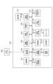
図2は本実施例における撮像装置100の構成の一例を示すブロック図である。
<Configuration of imaging device 100>
FIG. 2 is a block diagram showing an example of the configuration of the image pickup apparatus 100 according to this embodiment.

光学レンズ300は、撮像装置100に着脱可能なレンズユニットである。例えば光学レンズ300はズームレンズまたはバリフォーカルレンズである。光学レンズ300は光学レンズ、光学レンズを駆動させるためのモータ、および後述する撮像装置100のレンズ制御部102と通信する通信部を有する。光学レンズ300は、通信部によって受信した制御信号に基づいて、光学レンズをモータによって移動させることで、被写体に対するフォーカスおよびズーミング、並びに、手ブレの補正ができる。 The optical lens 300 is a lens unit that can be attached to and detached from the imaging device 100. For example, the optical lens 300 is a zoom lens or a varifocal lens. The optical lens 300 has an optical lens, a motor for driving the optical lens, and a communication unit that communicates with the lens control unit 102 of the imaging device 100 described below. The optical lens 300 can focus and zoom on a subject and correct camera shake by moving the optical lens using the motor based on a control signal received by the communication unit.

撮像部101は、光学レンズ300を経て撮像面に結像された被写体の光学像を電気信号に変換するための撮像素子、および撮像素子で生成された電気信号から画像データまたは動画データを生成して出力する画像処理部とを有する。撮像素子は、例えばCCD(Charge Coupled Device)、およびCMOS(Complementary Metal Oxide Semiconductor)である。本実施例では、撮像部101において静止画像データや動画データを含む画像データを生成して撮像部101から出力する一連の処理を「撮影」という。撮像装置100では、画像データは、DCF(Design rule for Camera File system)規格に従って、後述する記録媒体110に記録される。 The imaging unit 101 has an imaging element for converting an optical image of a subject formed on an imaging surface via an optical lens 300 into an electrical signal, and an image processing unit for generating and outputting image data or video data from the electrical signal generated by the imaging element. The imaging element is, for example, a charge coupled device (CCD) or a complementary metal oxide semiconductor (CMOS). In this embodiment, a series of processes for generating image data including still image data and video data in the imaging unit 101 and outputting the image data from the imaging unit 101 is called "shooting". In the imaging device 100, the image data is recorded on a recording medium 110 (described later) in accordance with the DCF (Design rule for Camera File system) standard.

レンズ制御部102は撮像部101から出力されたデータ、および後述する制御部111から出力された制御信号に基づいて、通信端子10を介して光学レンズ300に制御信号を送信し、光学レンズ300を制御する。 The lens control unit 102 transmits a control signal to the optical lens 300 via the communication terminal 10 based on the data output from the imaging unit 101 and a control signal output from the control unit 111 described later, and controls the optical lens 300.

情報取得部103は、撮像装置100の傾きおよび撮像装置100の筐体内の温度などを検出する。例えば情報取得部103は撮像装置100の傾きを加速度センサまたはジャイロセンサによって検出する。また、例えば情報取得部103は撮像装置100の筐体内の温度を温度センサによって検出する。 The information acquisition unit 103 detects the tilt of the imaging device 100 and the temperature inside the housing of the imaging device 100. For example, the information acquisition unit 103 detects the tilt of the imaging device 100 using an acceleration sensor or a gyro sensor. Also, for example, the information acquisition unit 103 detects the temperature inside the housing of the imaging device 100 using a temperature sensor.

音声入力部104は、マイクによって取得された音声から音声データを生成する。音声入力部104は、マイクによって撮像装置100の周辺の音声を取得し、取得された音声に対してアナログデジタル変換(A/D変換)、各種の音声処理を行い、音声データを生成する。本実施例では、音声入力部104はマイクを有する。音声入力部104の詳細な構成例については後述する。 The audio input unit 104 generates audio data from audio acquired by a microphone. The audio input unit 104 acquires audio around the imaging device 100 by the microphone, performs analog-to-digital conversion (A/D conversion) and various audio processes on the acquired audio, and generates audio data. In this embodiment, the audio input unit 104 has a microphone. A detailed configuration example of the audio input unit 104 will be described later.

揮発性メモリ105は、撮像部101において生成された画像データ、並びに音声入力部104によって生成された音声データを一時的に記録する。また、揮発性メモリ105は、表示部107に表示される画像データの一時的な記録領域、および制御部111の作業領域等としても使用される。 The volatile memory 105 temporarily records image data generated by the imaging unit 101 and audio data generated by the audio input unit 104. The volatile memory 105 is also used as a temporary storage area for image data displayed on the display unit 107, a working area for the control unit 111, etc.

表示制御部106は、撮像部101から出力された画像データ、対話的な操作のための文字並びに、メニュー画面等を表示部107に表示するよう制御する。また、表示制御部106は静止画撮影および動画撮影の際、撮像部101から出力されたデジタルデータを逐次表示部107に表示するよう制御することで、表示部107を電子ビューファインダとして機能させることができる。例えば表示部107は、液晶ディスプレイまたは有機ELディスプレイである。また、表示制御部106は、撮像部101から出力された画像データおよび動画データ、対話的な操作のための文字、並びにメニュー画面等を、後述する外部出力部115を介して外部のディスプレイに表示させるよう制御することもできる。 The display control unit 106 controls the display unit 107 to display image data output from the imaging unit 101, characters for interactive operation, menu screens, etc. The display control unit 106 can also control the display unit 107 to sequentially display digital data output from the imaging unit 101 during still image shooting and video shooting, thereby allowing the display unit 107 to function as an electronic viewfinder. For example, the display unit 107 is a liquid crystal display or an organic EL display. The display control unit 106 can also control the image data and video data output from the imaging unit 101, characters for interactive operation, menu screens, etc. to be displayed on an external display via the external output unit 115 described later.

符号化処理部108は、揮発性メモリ105に一時的に記録された画像データおよび音声データをそれぞれ符号化することができる。例えば、符号化処理部108は、画像データをJPEG規格またはRAW画像フォーマットに従って符号化およびデータ圧縮された動画データを生成することができる。例えば、符号化処理部108は、動画データをMPEG2規格またはH.264/MPEG4-AVC規格に従って符号化およびデータ圧縮された動画データを生成することができる。また例えば、符号化処理部108は、音声データをAC3AAC規格、ATRAC規格、またはADPCM方式に従って符号化およびデータ圧縮された音声データを生成することができる。また、符号化処理部108は、例えばリニアPCM方式に従って音声データをデータ圧縮しないように符号化してもよい。 The encoding processing unit 108 can encode the image data and audio data temporarily recorded in the volatile memory 105. For example, the encoding processing unit 108 can generate moving image data by encoding and compressing the image data according to the JPEG standard or RAW image format. For example, the encoding processing unit 108 can generate moving image data by encoding and compressing the video data according to the MPEG2 standard or H.264/MPEG4-AVC standard. Also, for example, the encoding processing unit 108 can generate audio data by encoding and compressing the audio data according to the AC3AAC standard, the ATRAC standard, or the ADPCM method. Also, the encoding processing unit 108 may encode the audio data according to, for example, the linear PCM method so as not to compress the audio data.

記録制御部109は、データを記録媒体110に記録すること、および記録媒体110から読み出すことができる。例えば、記録制御部109は、符号化処理部108によって生成された静止画像データ、動画データ、および音声データを記録媒体110に記録すること、および記録媒体110から読み出すことができる。記録媒体110は例えばSDカード、CFカード、XQDメモリーカード、HDD(磁気ディスク)、光学式ディスク、および半導体メモリである。記録媒体110は、撮像装置100に着脱可能なように構成してもよいし、撮像装置100に内蔵されていてもよい。すなわち、記録制御部109は少なくとも記録媒体110にアクセスする手段を有していればよい。 The recording control unit 109 can record data to the recording medium 110 and read data from the recording medium 110. For example, the recording control unit 109 can record still image data, video data, and audio data generated by the encoding processing unit 108 to the recording medium 110 and read the data from the recording medium 110. The recording medium 110 is, for example, an SD card, a CF card, an XQD memory card, a HDD (magnetic disk), an optical disk, or a semiconductor memory. The recording medium 110 may be configured to be detachable from the imaging device 100, or may be built into the imaging device 100. In other words, the recording control unit 109 only needs to have a means for accessing at least the recording medium 110.

制御部111は、入力された信号、および後述のプログラムに従ってデータバス116を介して撮像装置100の各構成要素を制御する。制御部111は、各種制御を実行するためのCPU、ROM、およびRAMを有する。なお、制御部111が撮像装置100全体を制御する代わりに、複数のハードウェアが分担して撮像装置全体を制御してもよい。制御部111が有するROMには、各構成要素を制御するためのプログラムが格納されている。また制御部111が有するRAMは演算処理等に利用される揮発性メモリである。 The control unit 111 controls each component of the imaging device 100 via the data bus 116 in accordance with the input signals and a program described below. The control unit 111 has a CPU, ROM, and RAM for executing various controls. Note that instead of the control unit 111 controlling the entire imaging device 100, multiple pieces of hardware may share the control of the entire imaging device. The ROM of the control unit 111 stores programs for controlling each component. The RAM of the control unit 111 is a volatile memory used for calculation processing, etc.

操作部112は、撮像装置100に対する指示をユーザから受け付けるためのユーザインタフェースである。操作部112は、例えば撮像装置100の電源をオン状態またはオフ状態にするための電源スイッチ72、撮影を指示するためのレリーズスイッチ61、画像データまたは動画データの再生を指示するための再生ボタン、およびモード切替スイッチ60等を有する。 The operation unit 112 is a user interface for receiving instructions from the user for the imaging device 100. The operation unit 112 has, for example, a power switch 72 for turning the power of the imaging device 100 on or off, a release switch 61 for issuing an instruction to shoot, a playback button for issuing an instruction to play back image data or video data, and a mode change switch 60.

操作部112はユーザの操作に応じて、制御信号を制御部111に出力する。また、表示部107に形成されるタッチパネルも操作部112に含めることができる。なお、レリーズスイッチ61は、SW1およびSW2を有する。レリーズスイッチ61が、いわゆる半押し状態となることにより、SW1がオンとなる。これにより、AF(オートフォーカス)処理、AE(自動露出)処理、AWB(オートホワイトバランス)処理、EF(フラッシュプリ発光)処理等の撮像の準備動作を行うための準備指示を受け付ける。また、レリーズスイッチ61が、いわゆる全押し状態となることにより、SW2がオンとなる。このようなユーザ操作により、撮像動作を行うための撮像指示を受け付ける。また、操作部112は後述するスピーカ114から再生される音声データの音量を調整することができる操作部材(例えばボタン)を含む。 The operation unit 112 outputs a control signal to the control unit 111 in response to a user's operation. The operation unit 112 can also include a touch panel formed on the display unit 107. The release switch 61 has SW1 and SW2. When the release switch 61 is pressed halfway, SW1 is turned on. This accepts a preparation instruction for performing a preparation operation for imaging, such as AF (autofocus) processing, AE (auto exposure) processing, AWB (auto white balance) processing, and EF (pre-flash) processing. When the release switch 61 is pressed fully, SW2 is turned on. This user operation accepts an imaging instruction for performing an imaging operation. The operation unit 112 also includes an operating member (e.g., a button) that can adjust the volume of audio data reproduced from a speaker 114, which will be described later.

音声出力部113は、音声データをスピーカ114、および外部出力部115に出力することができる。音声出力部113に入力される音声データは、記録制御部109により記録媒体110から読み出された音声データ、不揮発性メモリ117から出力される音声データ、および符号化処理部から出力される音声データである。スピーカ114は、音声データを再生することができる電気音響変換器である。 The audio output unit 113 can output audio data to the speaker 114 and the external output unit 115. The audio data input to the audio output unit 113 is audio data read from the recording medium 110 by the recording control unit 109, audio data output from the non-volatile memory 117, and audio data output from the encoding processing unit. The speaker 114 is an electro-acoustic transducer that can play back audio data.

外部出力部115は、画像データ、動画データ、および音声データなどを外部機器に出力することができる。外部出力部115は、例えば映像端子、マイク端子、およびヘッドホン端子等で構成される。 The external output unit 115 can output image data, video data, audio data, and the like to an external device. The external output unit 115 is composed of, for example, a video terminal, a microphone terminal, and a headphone terminal.

データバス116は、音声データ、動画データ、および画像データ等の各種データ、各種制御信号を撮像装置100の各ブロックへ伝達するためのデータバスである。 Data bus 116 is a data bus for transmitting various data such as audio data, video data, and image data, as well as various control signals, to each block of imaging device 100.

不揮発性メモリ117は不揮発性メモリであり、制御部111で実行される後述のプログラム等が格納される。また、不揮発性メモリ117には、音声データが記録されている。この音声データは例えば、被写体に合焦した場合に出力される合焦音、撮影を指示された場合に出力される電子シャッター音、撮像装置100を操作された場合に出力される操作音等の電子音の音声データである。 The non-volatile memory 117 is a non-volatile memory that stores programs executed by the control unit 111, which will be described later. The non-volatile memory 117 also stores audio data. This audio data is, for example, audio data of electronic sounds such as a focusing sound that is output when the subject is focused on, an electronic shutter sound that is output when an instruction to shoot is given, and an operation sound that is output when the imaging device 100 is operated.

<撮像装置100の動作>
これから、本実施例の撮像装置100の動作について説明する。
<Operation of Imaging Apparatus 100>
The operation of the imaging device 100 of this embodiment will now be described.

本実施例の撮像装置100は、ユーザが電源スイッチ72を操作して電源をオンされたことに応じて、不図示の電源から、撮像装置の各構成要素に電力を供給する。例えば電源はリチウムイオン電池またはアルカリマンガン乾電池等の電池である。 In the imaging device 100 of this embodiment, when the user turns on the power by operating the power switch 72, power is supplied to each component of the imaging device from a power source (not shown). For example, the power source is a battery such as a lithium ion battery or an alkaline manganese dry battery.

制御部111は、電力が供給されたことに応じてモード切替スイッチ60の状態に基づいて、例えば、撮影モードおよび再生モードのどのモードで動作するかを判断する。動画記録モードでは、制御部111は撮像部101から出力された動画データと音声入力部104から出力された音声データとを1つの音声付き動画データとして記録する。再生モードでは、制御部111は記録媒体110に記録された画像データまたは動画データを記録制御部109によって読み出し、表示部107に表示するよう制御する。 When power is supplied, the control unit 111 determines whether the camera will operate in a shooting mode or a playback mode, for example, based on the state of the mode changeover switch 60. In the video recording mode, the control unit 111 records the video data output from the imaging unit 101 and the audio data output from the audio input unit 104 as one piece of video data with audio. In the playback mode, the control unit 111 reads out the image data or video data recorded on the recording medium 110 using the recording control unit 109, and controls the display unit 107 to display it.

まず、動画記録モードについて説明する。動画記録モードでは、まず制御部111は、撮像装置100を撮影待機状態に移行させるように制御信号を撮像装置100の各構成要素に送信する。例えば、制御部111は、撮像部101および音声入力部104に以下のような動作をさせるよう制御する。 First, the video recording mode will be described. In the video recording mode, the control unit 111 first transmits a control signal to each component of the imaging device 100 to transition the imaging device 100 to a shooting standby state. For example, the control unit 111 controls the imaging unit 101 and the audio input unit 104 to perform the following operations.

撮像部101は、光学レンズ300を経て撮像面に結像された被写体の光学像を電気信号に変換し、撮像素子で生成された電気信号から動画データを生成する。そして、撮像部101は動画データを表示制御部106に送信し、表示部107によって表示する。ユーザは表示部107に表示された動画データを見ながら撮影の準備を行うことができる。 The imaging unit 101 converts the optical image of the subject formed on the imaging surface via the optical lens 300 into an electrical signal, and generates video data from the electrical signal generated by the imaging element. The imaging unit 101 then transmits the video data to the display control unit 106, which displays it on the display unit 107. The user can prepare for shooting while viewing the video data displayed on the display unit 107.

音声入力部104は、複数のマイクから入力されたアナログ音声信号をそれぞれA/D変換し、複数のデジタル音声信号を生成する。そして音声入力部104はその複数のデジタル音声信号から複数のチャンネルの音声データを生成する。音声入力部104は生成された音声データを音声出力部113に送信し、スピーカ114から音声データを再生させる。ユーザは、スピーカ114から再生された音声データを聞きながら、音声付き動画データに記録される音声データの音量を操作部112によって調整することができる。 The audio input unit 104 A/D converts analog audio signals input from multiple microphones to generate multiple digital audio signals. The audio input unit 104 then generates multiple channels of audio data from the multiple digital audio signals. The audio input unit 104 transmits the generated audio data to the audio output unit 113, which plays the audio data from the speaker 114. While listening to the audio data played from the speaker 114, the user can use the operation unit 112 to adjust the volume of the audio data recorded in the video data with audio.

次に、ユーザによってLVボタン76が押下されたことに応じて、制御部111は、撮像装置100の各構成要素に撮影開始の指示信号を送信する。例えば、制御部111は、撮像部101、音声入力部104、符号化処理部108、および記録制御部109に以下のような動作をさせるよう制御する。 Next, in response to the user pressing the LV button 76, the control unit 111 transmits an instruction signal to start shooting to each component of the imaging device 100. For example, the control unit 111 controls the imaging unit 101, the audio input unit 104, the encoding processing unit 108, and the recording control unit 109 to perform the following operations.

撮像部101は、光学レンズ300を経て撮像面に結像された被写体の光学像を電気信号に変換し、撮像素子で生成された電気信号から動画データを生成する。そして、撮像部101は動画データを表示制御部106に送信し、表示部107によって表示する。また、また撮像部101は生成された動画データを揮発性メモリ105へ送信する。 The imaging unit 101 converts the optical image of the subject formed on the imaging surface via the optical lens 300 into an electrical signal, and generates video data from the electrical signal generated by the imaging element. The imaging unit 101 then transmits the video data to the display control unit 106, which displays the video data on the display unit 107. The imaging unit 101 also transmits the generated video data to the volatile memory 105.

音声入力部104は、複数のマイクから入力されたアナログ音声信号をそれぞれA/D変換し、複数のデジタル音声信号を生成する。そして音声入力部104はその複数のデジタル音声信号からマルチチャンネルの音声データを生成する。そして、音声入力部104は生成された音声データを揮発性メモリ105へ送信する。 The audio input unit 104 performs A/D conversion on the analog audio signals input from the multiple microphones, and generates multiple digital audio signals. The audio input unit 104 then generates multi-channel audio data from the multiple digital audio signals. The audio input unit 104 then transmits the generated audio data to the volatile memory 105.

符号化処理部108は、揮発性メモリ105に一時的に記録された動画データおよび音声データを読み出してそれぞれ符号化する。制御部111は、符号化処理部108によって符号化された動画データおよび音声データからデータストリームを生成し、記録制御部109に出力する。記録制御部109は、UDFまたはFAT等のファイルシステムに従って、入力されたデータストリームを音声付き動画データとして記録媒体110に記録していく。 The encoding processing unit 108 reads out the video data and audio data temporarily recorded in the volatile memory 105 and encodes each of them. The control unit 111 generates a data stream from the video data and audio data encoded by the encoding processing unit 108 and outputs it to the recording control unit 109. The recording control unit 109 records the input data stream as video data with audio on the recording medium 110 according to a file system such as UDF or FAT.

撮像装置100の各構成要素は以上の動作を動画撮影中において継続する。 Each component of the imaging device 100 continues to perform the above operations while shooting video.

そして、ユーザからLVボタン76が押下されたことに応じて、制御部111は、撮像装置100の各構成要素に撮影終了の指示信号を送信する。例えば、制御部111は撮像部101、音声入力部104、符号化処理部108、および記録制御部109に以下のような動作をさせるよう制御する。 Then, in response to the user pressing the LV button 76, the control unit 111 transmits an instruction signal to end shooting to each component of the imaging device 100. For example, the control unit 111 controls the imaging unit 101, the audio input unit 104, the encoding processing unit 108, and the recording control unit 109 to perform the following operations.

撮像部101は、動画データの生成を停止する。音声入力部104は、音声データの生成を停止する。 The imaging unit 101 stops generating video data. The audio input unit 104 stops generating audio data.

符号化処理部108は、揮発性メモリ105に記録されている残りの動画データおよび音声データを読み出して符号化する。制御部111は、符号化処理部108によって符号化された動画データおよび音声データからデータストリームを生成し、記録制御部109に出力する。 The encoding processing unit 108 reads out and encodes the remaining video data and audio data recorded in the volatile memory 105. The control unit 111 generates a data stream from the video data and audio data encoded by the encoding processing unit 108 and outputs it to the recording control unit 109.

記録制御部109は、UDFまたはFAT等のファイルシステムに従って、データストリームを音声付き動画データのファイルとして記録媒体110に記録していく。そして、記録制御部109は、データストリームの入力が停止したことに応じて、音声付き動画データを完成させる。音声付き動画データの完成をもって、撮像装置100の記録動作は停止する。 The recording control unit 109 records the data stream as a file of video data with audio on the recording medium 110 according to a file system such as UDF or FAT. Then, when the input of the data stream stops, the recording control unit 109 completes the video data with audio. When the video data with audio is completed, the recording operation of the imaging device 100 stops.

制御部111は、記録動作が停止したことに応じて、撮影待機状態に移行させるように制御信号を撮像装置100の各構成要素に送信する。これにより、制御部111は撮像装置100を撮影待機状態に戻るよう制御する。 In response to the recording operation being stopped, the control unit 111 transmits a control signal to each component of the imaging device 100 to transition to a shooting standby state. As a result, the control unit 111 controls the imaging device 100 to return to the shooting standby state.

次に、再生モードについて説明する。再生モードでは、制御部111は、再生状態に移行させるように制御信号を撮像装置100の各構成要素に送信する。例えば、制御部111は符号化処理部108、記録制御部109、表示制御部106、および音声出力部113に以下のような動作をさせるよう制御する。 Next, the playback mode will be described. In the playback mode, the control unit 111 transmits a control signal to each component of the imaging device 100 to transition to a playback state. For example, the control unit 111 controls the encoding processing unit 108, the recording control unit 109, the display control unit 106, and the audio output unit 113 to perform the following operations.

記録制御部109は、記録媒体110に記録された音声付き動画データを読み出して読みだした音声付き動画データを符号化処理部108に送信する。 The recording control unit 109 reads the video data with audio recorded on the recording medium 110 and transmits the read video data with audio to the encoding processing unit 108.

符号化処理部108は、音声付き動画データから画像データ、および音声データを復号化する。符号化処理部108は、復号化された動画データを表示制御部106へ、復号化された音声データを音声出力部113へ、それぞれ送信する。 The encoding processing unit 108 decodes the video data with audio into image data and audio data. The encoding processing unit 108 transmits the decoded video data to the display control unit 106 and the decoded audio data to the audio output unit 113.

表示制御部106は、復号化された画像データを表示部107によって表示する。音声出力部113は、復号化された音声データをスピーカ114によって再生する。 The display control unit 106 displays the decoded image data on the display unit 107. The audio output unit 113 plays the decoded audio data through the speaker 114.

以上のように、本実施例の撮像装置100は画像データ、および音声データを記録および再生することができる。 As described above, the imaging device 100 of this embodiment can record and play back image data and audio data.

本実施例では、音声入力部104は、マイクから入力された音声信号のレベルの調整処理等の音声処理を実行する。本実施例では、音声入力部104は動画記録が開始されたことに応じてこの音声処理を実行する。なお、この音声処理は、撮像装置100の電源がオンにされてから実行されてもよい。また、この音声処理は、撮影モードが選択されたことに応じて実行されてもよい。また、この音声処理は、動画記録モードおよび音声メモ機能等の音声の記録に関連するモードが選択されたことに応じて実行されてもよい。また、この音声処理は、音声信号の記録が開始したことに応じて実行されてもよい。 In this embodiment, the audio input unit 104 performs audio processing such as adjusting the level of the audio signal input from the microphone. In this embodiment, the audio input unit 104 performs this audio processing in response to the start of video recording. Note that this audio processing may be performed after the power of the imaging device 100 is turned on. Also, this audio processing may be performed in response to the selection of a shooting mode. Also, this audio processing may be performed in response to the selection of a mode related to audio recording, such as a video recording mode or an audio memo function. Also, this audio processing may be performed in response to the start of recording of the audio signal.

<音声入力部104の構成>
図3は本実施例における音声入力部104の詳細な構成の一例を示すブロック図である。
<Configuration of voice input unit 104>
FIG. 3 is a block diagram showing an example of a detailed configuration of the voice input unit 104 in this embodiment.

本実施例において、音声入力部104は、Lマイク201a、Rマイク201b、およびノイズマイク201cの3つのマイクを有する。Lマイク201aおよびRマイク201bはそれぞれ第一のマイクの一例である。本実施例では、撮像装置100は環境音をLマイク201aおよびRマイク201bによって収音し、Lマイク201aおよびRマイク201bから入力された音声信号をステレオ方式で記録する。例えば環境音は、ユーザの音声、動物の鳴き声、雨音、および楽曲等の撮像装置100の筐体外および光学レンズ300の筐体外において発生する音である。 In this embodiment, the audio input unit 104 has three microphones: an L microphone 201a, an R microphone 201b, and a noise microphone 201c. The L microphone 201a and the R microphone 201b are each an example of a first microphone. In this embodiment, the imaging device 100 picks up environmental sounds using the L microphone 201a and the R microphone 201b, and records the audio signals input from the L microphone 201a and the R microphone 201b in a stereo format. For example, environmental sounds are sounds generated outside the housing of the imaging device 100 and outside the housing of the optical lens 300, such as the user's voice, animal cries, the sound of rain, and music.

また、ノイズマイク201cは第2のマイクの一例である。ノイズマイク201cは、撮像装置100の筐体内、および光学レンズ300の筐体内で発生する、所定の騒音源(ノイズ源)からの駆動音等の騒音(ノイズ)を取得するためのマイクである。ノイズ源は例えば、超音波モータ(Ultrasonic Motor、以下USM)およびステッピングモータ(Stepper Motor、以下STM)などのモータである。騒音(ノイズ)は例えば、USMおよびSTM等のモータの駆動によって発生する振動音である。例えば、モータは被写体に合焦するためのAF処理において駆動する。撮像装置100は撮像装置100の筐体内、および光学レンズ300の筐体内で発生する駆動音等の騒音(ノイズ)をノイズマイク201cによって取得し、取得したノイズの音声データを用いて、後述するノイズパラメータを生成する。なお、本実施例では、Lマイク201a、Rマイク201b、およびノイズマイク201cは無指向性のマイクである。本実施例における、Lマイク201a、Rマイク201b、およびノイズマイク201cの配置例は図4を用いて後述する。 The noise microphone 201c is an example of a second microphone. The noise microphone 201c is a microphone for acquiring noise (noise), such as a driving sound from a predetermined noise source (noise source) generated within the housing of the imaging device 100 and the housing of the optical lens 300. The noise source is, for example, a motor such as an ultrasonic motor (USM) and a stepper motor (STM). The noise (noise) is, for example, a vibration sound generated by driving a motor such as a USM and an STM. For example, the motor is driven in an AF process for focusing on a subject. The imaging device 100 acquires noise (noise), such as a driving sound generated within the housing of the imaging device 100 and the housing of the optical lens 300, using the noise microphone 201c, and generates a noise parameter to be described later using the audio data of the acquired noise. In this embodiment, the L microphone 201a, the R microphone 201b, and the noise microphone 201c are non-directional microphones. An example of the arrangement of the L microphone 201a, the R microphone 201b, and the noise microphone 201c in this embodiment will be described later with reference to FIG. 4.

Lマイク201a、Rマイク201b、およびノイズマイク201cは、それぞれ取得した音声からアナログ音声信号を生成し、A/D変換部202に入力する。ここで、Lマイク201aから入力される音声信号をLch、Rマイク201bから入力される音声信号をRch、およびノイズマイク201cから入力される音声信号をNchと記載する。 The L microphone 201a, the R microphone 201b, and the noise microphone 201c each generate an analog audio signal from the captured sound and input it to the A/D conversion unit 202. Here, the audio signal input from the L microphone 201a is referred to as Lch, the audio signal input from the R microphone 201b as Rch, and the audio signal input from the noise microphone 201c as Nch.

A/D変換部202は、Lマイク201a、Rマイク201b、およびノイズマイク201cから入力されたアナログ音声信号をデジタル音声信号に変換する。A/D変換部202は変換されたデジタル音声信号をFFT部203に出力する。本実施例においてA/D変換部202はサンプリング周波数を48kHz、およびビット深度を16bitとして標本化処理を実行することで、アナログ音声信号をデジタル音声信号に変換する。 The A/D conversion unit 202 converts the analog audio signals input from the L microphone 201a, the R microphone 201b, and the noise microphone 201c into digital audio signals. The A/D conversion unit 202 outputs the converted digital audio signals to the FFT unit 203. In this embodiment, the A/D conversion unit 202 converts the analog audio signals into digital audio signals by performing sampling processing with a sampling frequency of 48 kHz and a bit depth of 16 bits.

FFT部203は、A/D変換部202から入力された時間領域のデジタル音声信号に高速フーリエ変換処理を施し、周波数領域のデジタル音声信号に変換する。本実施例において、周波数領域のデジタル音声信号は、0Hzから48kHzまでの周波数帯域において、1024ポイントの周波数スペクトルを有する。また、周波数領域のデジタル音声信号は、0Hzからナイキスト周波数である24kHzまでの周波数帯域においては、513ポイントの周波数スペクトルを有する。本実施例では、撮像装置100は、FFT部203から出力された音声データのうち、0Hzから24kHzまでの513ポイントの周波数スペクトルを利用して、ノイズ低減の処理を行う。 The FFT unit 203 performs fast Fourier transform processing on the time-domain digital audio signal input from the A/D conversion unit 202, converting it into a frequency-domain digital audio signal. In this embodiment, the frequency-domain digital audio signal has a frequency spectrum of 1024 points in the frequency band from 0 Hz to 48 kHz. Also, the frequency-domain digital audio signal has a frequency spectrum of 513 points in the frequency band from 0 Hz to 24 kHz, which is the Nyquist frequency. In this embodiment, the imaging device 100 performs noise reduction processing using the 513-point frequency spectrum from 0 Hz to 24 kHz of the audio data output from the FFT unit 203.

ここで、高速フーリエ変換されたLchの周波数スペクトルを、Lch_Before[0]~Lch_Before[512]の513ポイントの配列データで表す。これらの配列データを総称する場合、Lch_Beforeと記載する。また、高速フーリエ変換されたRchの周波数スペクトルを、Rch_Before[0]~Rch_Before[512]の513ポイントの配列データで表す。これらの配列データを総称する場合、Rch_Beforeと記載する。なお、Lch_Beforeおよび、Rch_Beforeはそれぞれ第1の周波数スペクトルデータの一例である。 Here, the frequency spectrum of the Lch after the fast Fourier transform is represented by array data of 513 points from Lch_Before[0] to Lch_Before[512]. When these array data are referred to collectively, they are written as Lch_Before. Moreover, the frequency spectrum of the Rch after the fast Fourier transform is represented by array data of 513 points from Rch_Before[0] to Rch_Before[512]. When these array data are referred to collectively, they are written as Rch_Before. Moreover, Lch_Before and Rch_Before are each an example of the first frequency spectrum data.

また、高速フーリエ変換されたNchの周波数スペクトルを、Nch_Before[0]~Nch_Before[512]の513ポイントの配列データで表す。これらの配列データを総称する場合、Nch_Beforeと記載する。なお、Nch_Beforeは第2の周波数スペクトルデータの一例である。 The frequency spectrum of Nch after fast Fourier transformation is represented by array data of 513 points, Nch_Before[0] to Nch_Before[512]. When these array data are collectively referred to, they are written as Nch_Before. Note that Nch_Before is an example of second frequency spectrum data.

ノイズデータ生成部204は、Nch_Beforeに基づいて、Lch_BeforeおよびRch_Beforeに含まれるノイズを低減するためのデータを生成する。本実施例では、ノイズデータ生成部204は、Lch_Before[0]~Lch_Before[512]に含まれるノイズをそれぞれ低減するためのNL[0]~NL[512]の配列データをノイズパラメータを用いて生成する。また、ノイズデータ生成部204は、Rch_Before[0]~Rch_Before[512]に含まれるノイズをそれぞれ低減するためのNR[0]~NR[512]の配列データを生成する。NL[0]~NL[512]の配列データにおける周波数のポイントは、Lch_Before[0]~Lch_Before[512]の配列データにおける周波数のポイントと同じである。また、NR[0]~NR[512]の配列データにおける周波数のポイントは、Rch_Before[0]~Rch_Before[512]の配列データにおける周波数のポイントと同じである。 The noise data generating unit 204 generates data for reducing noise contained in Lch_Before and Rch_Before based on Nch_Before. In this embodiment, the noise data generating unit 204 generates array data NL[0] to NL[512] for reducing noise contained in Lch_Before[0] to Lch_Before[512] using noise parameters. The noise data generating unit 204 also generates array data NR[0] to NR[512] for reducing noise contained in Rch_Before[0] to Rch_Before[512]. The frequency points in the array data NL[0] to NL[512] are the same as the frequency points in the array data Lch_Before[0] to Lch_Before[512]. Additionally, the frequency points in the array data NR[0] to NR[512] are the same as the frequency points in the array data Rch_Before[0] to Rch_Before[512].

なお、NL[0]~NL[512]の配列データを総称する場合、NLと記載する。また、NR[0]~NR[512]を総称する場合、NRと記載する。NLおよびNRはそれぞれ第3の周波数スペクトルデータの一例である。 Note that the array data NL[0] to NL[512] are collectively referred to as NL. Furthermore, the array data NR[0] to NR[512] are collectively referred to as NR. NL and NR are each an example of the third frequency spectrum data.

ノイズパラメータ記録部205には、ノイズデータ生成部204がNch_BeforeからをNLおよびNRを生成するためのノイズパラメータが記録されている。ノイズパラメータ記録部205はノイズの種類に応じた複数種類のノイズパラメータを記録している。Nch_BeforeからNLを生成するためのノイズパラメータを総称する場合、PLxと記載する。Nch_BeforeからNRを生成するためのノイズパラメータを総称する場合、PRxと記載する。 The noise parameter recording unit 205 records noise parameters that the noise data generating unit 204 uses to generate NL and NR from Nch_Before. The noise parameter recording unit 205 records multiple types of noise parameters according to the type of noise. The noise parameters for generating NL from Nch_Before are collectively referred to as PLx. The noise parameters for generating NR from Nch_Before are collectively referred to as PRx.

PLxおよびPRxはそれぞれNLおよびNRと同じ配列数を有する。例えば、PL1は、PL1[0]~PL1[512]の配列データである。また、PL1の周波数ポイントは、Lch_Beforeの周波数ポイントと同じである。また例えばPR1は、PR1[0]~PR1[512]の配列データである。PR1の周波数ポイントは、Rch_Beforeと同じ周波数ポイントである。ノイズパラメータは図5を用いて後述する。 PLx and PRx have the same number of arrays as NL and NR, respectively. For example, PL1 is array data from PL1[0] to PL1[512]. The frequency points of PL1 are the same as the frequency points of Lch_Before. For example, PR1 is array data from PR1[0] to PR1[512]. The frequency points of PR1 are the same as the frequency points of Rch_Before. The noise parameters will be described later with reference to Figure 5.

ノイズパラメータ選択部206は、ノイズパラメータ記録部205に記録されているノイズパラメータから、ノイズデータ生成部204において使用されるノイズパラメータを決定する。ノイズパラメータ選択部206は、Lch_Before、Rch_Before、Nch_Before、およびレンズ制御部102から受信したデータに基づいて、ノイズデータ生成部204において用いられるノイズパラメータを決定する。ノイズパラメータ選択部206の動作については図8を用いて詳しく後述する。 The noise parameter selection unit 206 determines the noise parameters to be used in the noise data generation unit 204 from the noise parameters recorded in the noise parameter recording unit 205. The noise parameter selection unit 206 determines the noise parameters to be used in the noise data generation unit 204 based on Lch_Before, Rch_Before, Nch_Before, and data received from the lens control unit 102. The operation of the noise parameter selection unit 206 will be described in detail later with reference to FIG. 8.

なお、本実施例では、ノイズパラメータ記録部205には、ノイズパラメータとして513ポイントの周波数スペクトルそれぞれに対する係数がすべて記録されている。しかし、513ポイントの全ての周波数に対する係数ではなく、少なくともノイズを低減するために必要な周波数ポイントの係数が記録されていればよい。例えば、ノイズパラメータ記録部205は、ノイズパラメータとして、典型的な可聴周波数と考えられている20Hz~20kHzの周波数スペクトルそれぞれに対する係数を記録し、他の周波数スペクトルの係数を記録しなくてもよい。また例えば、ノイズパラメータとして、係数の値がゼロである周波数スペクトルに対する係数はノイズパラメータ記録部205に記録されていなくてもよい。 In this embodiment, the noise parameter recording unit 205 records all of the coefficients for each of the 513 frequency spectrum points as noise parameters. However, it is sufficient that at least the coefficients for the frequency points necessary to reduce noise are recorded, not the coefficients for all of the 513 frequency points. For example, the noise parameter recording unit 205 may record, as noise parameters, coefficients for each frequency spectrum of 20 Hz to 20 kHz, which are considered to be typical audible frequencies, and may not record coefficients for other frequency spectra. Also, for example, coefficients for frequency spectra whose coefficient value is zero may not be recorded in the noise parameter recording unit 205 as noise parameters.

減算処理部207は、Lch_BeforeおよびRch_BeforeからNLおよびNRをそれぞれ減算する。例えば、減算処理部207はLch_BeforeからNLを減算するL減算器207a、およびRch_BeforeからNRを減算するR減算器207bを有する。L減算器207aはLch_BeforeからNLを減算し、Lch_After[0]~Lch_After[512]の513ポイントの配列データを出力する。R減算器207bはRch_BeforeからNRを減算し、Rch_After[0]~Rch_After[512]の513ポイントの配列データを出力する。本実施例では、減算処理部207はスペクトルサブトラクション法によって減算処理を実行する。 The subtraction processing unit 207 subtracts NL and NR from Lch_Before and Rch_Before, respectively. For example, the subtraction processing unit 207 has an L subtractor 207a that subtracts NL from Lch_Before, and an R subtractor 207b that subtracts NR from Rch_Before. The L subtractor 207a subtracts NL from Lch_Before, and outputs array data of 513 points from Lch_After[0] to Lch_After[512]. The R subtractor 207b subtracts NR from Rch_Before, and outputs array data of 513 points from Rch_After[0] to Rch_After[512]. In this embodiment, the subtraction processing unit 207 performs subtraction processing using the spectral subtraction method.

iFFT部208は、減算処理部207から入力された周波数領域のデジタル音声信号を逆高速フーリエ変換(逆フーリエ変換)して時間領域のデジタル音声信号に変換する。 The iFFT unit 208 performs an inverse fast Fourier transform (inverse Fourier transform) on the frequency domain digital audio signal input from the subtraction processing unit 207 to convert it into a time domain digital audio signal.

音声処理部209は、イコライザ、オートレベルコントローラ、およびステレオ感の強調処理等の時間領域のデジタル音声信号に対する音声処理を実行する。音声処理部209は、音声処理を行った音声データを揮発性メモリ105へ出力する。 The audio processing unit 209 performs audio processing on the time domain digital audio signal, such as an equalizer, an auto level controller, and stereo enhancement processing. The audio processing unit 209 outputs the processed audio data to the volatile memory 105.

なお、本実施例では撮像装置100は第一のマイクとして2つのマイクを有するが、撮像装置100は第一のマイクを1つのマイクまたは3つ以上のマイクとしてもよい。例えば撮像装置100は、音声入力部104に第一のマイクとして1つのマイクを有する場合、1つのマイクによって収音された音声データをモノラル方式で記録する。また例えば撮像装置100は、音声入力部104に第一のマイクとして3つ以上のマイクを有する場合、3つ以上のマイクによって収音された音声データをサラウンド方式で記録する。 In this embodiment, the imaging device 100 has two microphones as the first microphone, but the imaging device 100 may have one microphone or three or more microphones as the first microphone. For example, when the imaging device 100 has one microphone as the first microphone in the audio input unit 104, the imaging device 100 records the audio data picked up by the one microphone in a monaural format. Also, when the imaging device 100 has three or more microphones as the first microphone in the audio input unit 104, the imaging device 100 records the audio data picked up by the three or more microphones in a surround format.

なお、本実施例では、Lマイク201a、Rマイク201b、およびノイズマイク201cは無指向性のマイクとしたが、これらのマイクは指向性マイクであってもよい。 In this embodiment, the L microphone 201a, the R microphone 201b, and the noise microphone 201c are non-directional microphones, but these microphones may also be directional microphones.

<音声入力部104のマイクの配置>
ここで、本実施例の音声入力部104のマイクの配置例を説明する。図4はLマイク201a、Rマイク201b、およびノイズマイク201cの配置例を示している。
<Arrangement of microphones in audio input unit 104>
Here, an example of the arrangement of the microphones in the voice input unit 104 of this embodiment will be described. Fig. 4 shows an example of the arrangement of the L microphone 201a, the R microphone 201b, and the noise microphone 201c.

図4は、Lマイク201a、Rマイク201b、およびノイズマイク201cが取り付けられた撮像装置100の部分の断面図の一例である。この撮像装置100の部分は、外装部302、マイクブッシュ303、および固定部304により構成される。 Figure 4 is an example of a cross-sectional view of a portion of the imaging device 100 to which the L microphone 201a, the R microphone 201b, and the noise microphone 201c are attached. This portion of the imaging device 100 is composed of an exterior part 302, a microphone bushing 303, and a fixed part 304.

外装部302は、マイクに環境音を入力するための穴(以下、マイク穴という)を有する。本実施例では、マイク穴はLマイク201a、およびRマイク201bの上方に形成される。一方、ノイズマイク201cは、撮像装置100の筐体内および光学レンズ300の筐体内において発生する駆動音を取得するために設けられており、環境音を取得する必要はない。したがって、本実施例では、外装部302にはノイズマイク201cの上方にマイク穴は形成されない。 The exterior part 302 has a hole (hereinafter referred to as a microphone hole) for inputting environmental sound to the microphone. In this embodiment, the microphone hole is formed above the L microphone 201a and the R microphone 201b. On the other hand, the noise microphone 201c is provided to acquire drive sounds generated within the housing of the imaging device 100 and within the housing of the optical lens 300, and does not need to acquire environmental sound. Therefore, in this embodiment, no microphone hole is formed in the exterior part 302 above the noise microphone 201c.

撮像装置100の筐体内および光学レンズ300の筐体内において発生する駆動音は、マイク穴を介してLマイク201a、およびRマイク201bにより取得される。環境音が小さい状態で撮像装置100および光学レンズ300の筐体内において駆動音等が発生した場合、各マイクが取得する音声は、主としてこの駆動音となる。そのため、Lマイク201a、Rマイク201bからの音声レベルよりも、ノイズマイク201cからの音声レベルの方が大きい。つまり、この場合、各マイクから出力される音声信号のレベルの関係は、以下のようになる。
Lch≒Rch<Nch
Drive sounds generated within the housings of the image capture device 100 and the optical lens 300 are picked up by the L microphone 201a and the R microphone 201b through the microphone holes. When drive sounds or the like are generated within the housings of the image capture device 100 and the optical lens 300 while the ambient sound is low, the sound picked up by each microphone is mainly this drive sound. Therefore, the sound level from the noise microphone 201c is higher than the sound levels from the L microphone 201a and the R microphone 201b. In other words, in this case, the relationship between the levels of the sound signals output from each microphone is as follows:
Lch≒Rch<Nch

また、環境音が大きくなると、マイク201cからの、撮像装置100または光学レンズ300で発生した駆動音の音声レベルよりも、Lマイク201a、Rマイク201bからの環境音の音声レベルの方が大きくなる。そのため、この場合、各マイクから出力される音声信号のレベルの関係は、以下のようになる。
Lch≒Rch>Nch
Furthermore, when the environmental sound becomes louder, the sound level of the environmental sound from the L microphone 201a and the R microphone 201b becomes louder than the sound level of the drive sound from the microphone 201c generated by the image capture device 100 or the optical lens 300. Therefore, in this case, the relationship between the levels of the audio signals output from each microphone is as follows:
Lch≒Rch>Nch

なお、本実施例では、外装部302に形成されるマイク穴の形状は楕円状であるが、円状または方形状等の他の形状でもよい。また、マイク201a上のマイク穴の形状とマイク201b上のマイク穴の形状とは、互いに異なっていてもよい。 In this embodiment, the shape of the microphone hole formed in the exterior part 302 is elliptical, but it may be other shapes such as circular or rectangular. Also, the shape of the microphone hole on the microphone 201a and the shape of the microphone hole on the microphone 201b may be different from each other.

なお、本実施例では、ノイズマイク201cは、Lマイク201aとRマイク201bに近接するように配置される。また、本実施例では、ノイズマイク201cは、Lマイク201aとRマイク201bの間に配置される。これにより、撮像装置100の筐体内および光学レンズ300の筐体内において発生する駆動音等からノイズマイク201cによって生成される音声信号は、この駆動音等からLマイク201aおよびRマイク201bによって生成される音声信号と似た信号になる。 In this embodiment, the noise microphone 201c is positioned close to the L microphone 201a and the R microphone 201b. Also, in this embodiment, the noise microphone 201c is positioned between the L microphone 201a and the R microphone 201b. As a result, the audio signal generated by the noise microphone 201c from the drive sounds etc. generated within the housing of the imaging device 100 and the housing of the optical lens 300 becomes a signal similar to the audio signal generated by the L microphone 201a and the R microphone 201b from this drive sound etc.

マイクブッシュ303は、Lマイク201a、Rマイク201b、およびノイズマイク201cを固定するための部材である。固定部304は、マイクブッシュ303を外装部302に固定する部材である。 The microphone bushing 303 is a member for fixing the L microphone 201a, the R microphone 201b, and the noise microphone 201c. The fixing part 304 is a member for fixing the microphone bushing 303 to the exterior part 302.

なお、本実施例では、外装部302および固定部304はPC材等のモールド部材で構成される。また、外装部302および固定部304はアルミまたはステンレス等の金属部材で構成されてもよい。また、本実施例では、マイクブッシュ303は、エチレンプロピレンジエンゴム等のゴム材で構成される。 In this embodiment, the exterior part 302 and the fixed part 304 are made of a molded material such as PC material. The exterior part 302 and the fixed part 304 may also be made of a metal material such as aluminum or stainless steel. In this embodiment, the microphone bushing 303 is made of a rubber material such as ethylene propylene diene rubber.

<ノイズパラメータ>
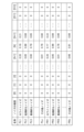
図5はノイズパラメータ記録部205に記録されているノイズパラメータの一例である。ノイズパラメータは、撮像装置100の筐体内、および光学レンズ300の筐体内において発生した駆動音をノイズマイク201cが取得することにより生成した音声信号を補正するためのパラメータである。図5に示すように、本実施例では、ノイズパラメータ記録部205にはPLxおよびPRxが記録されている。本実施例では、駆動音の発生源は光学レンズ300の筐体内であるとして説明する。光学レンズ300の筐体内で発生した駆動音はレンズマウント301を介して撮像装置100の筐体内に伝達し、Lマイク201a、Rマイク201b、およびノイズマイク201cによって取得される。
<Noise parameters>
Fig. 5 shows an example of noise parameters recorded in the noise parameter recording unit 205. The noise parameters are parameters for correcting an audio signal generated by the noise microphone 201c acquiring drive sounds generated in the housing of the image capture device 100 and the housing of the optical lens 300. As shown in Fig. 5, in this embodiment, PLx and PRx are recorded in the noise parameter recording unit 205. In this embodiment, the source of the drive sounds will be described as being inside the housing of the optical lens 300. The drive sounds generated inside the housing of the optical lens 300 are transmitted to the inside of the housing of the image capture device 100 via the lens mount 301, and are acquired by the L microphone 201a, the R microphone 201b, and the noise microphone 201c.

駆動音の種類によって、駆動音の周波数が異なる。そのため、本実施例では、撮像装置100は、駆動音(ノイズ)の種類に対応した複数のノイズパラメータを記録する。そして、これら複数のノイズパラメータのうちの何れかを用いてノイズデータを生成する。本実施例では、撮像装置100は、恒常的なノイズとしてホワイトノイズに対するノイズパラメータを記録する。また、撮像装置100は、例えば光学レンズ300内のギアがかみ合わさることによって発生する短期的なノイズに対するノイズパラメータを記録する。また、撮像装置100は、長期的なノイズとして、例えばレンズ300の筐体内における摺動音に対するノイズパラメータを記録する。他にも、撮像装置100は光学レンズ300の種類ごと、並びに、情報取得部103によって検出される撮像装置100の筐体内の温度および撮像装置100の傾きごとにノイズパラメータを記録してもよい。 The frequency of the drive sound varies depending on the type of drive sound. Therefore, in this embodiment, the imaging device 100 records multiple noise parameters corresponding to the type of drive sound (noise). Then, noise data is generated using one of these multiple noise parameters. In this embodiment, the imaging device 100 records noise parameters for white noise as constant noise. The imaging device 100 also records noise parameters for short-term noise generated, for example, by the meshing of gears in the optical lens 300. The imaging device 100 also records noise parameters for long-term noise, for example, sliding noise within the housing of the lens 300. In addition, the imaging device 100 may record noise parameters for each type of optical lens 300, and for each temperature within the housing of the imaging device 100 and tilt of the imaging device 100 detected by the information acquisition unit 103.

<ノイズデータの生成方法>
図6および図7を用いて、ノイズデータ生成部204におけるノイズデータの生成処理を説明する。ここではLchのデータに関するノイズデータの生成処理について説明するが、Rchのデータに関するノイズデータの生成方法も同様である。
<Method of generating noise data>
6 and 7, the process of generating noise data in the noise data generator 204 will be described. Here, the process of generating noise data relating to the Lch data will be described, but the method of generating noise data relating to the Rch data is similar.

まず、環境音がないと見なせる状況において、ノイズパラメータを生成する処理について説明する。図6(a)は、環境音がないと見なせる状況において光学レンズ300の筐体内で駆動音が発生した場合におけるLch_Beforeの周波数スペクトルの一例である。図6(b)は、環境音がないと見なせる状況において光学レンズ300の筐体内で駆動音が発生した場合におけるNch_Beforeの周波数スペクトルの一例である。横軸は0ポイント目から512ポイント目までの周波数を示す軸、縦軸は周波数スペクトルの振幅を示す軸である。 First, the process of generating noise parameters in a situation where it is considered that there is no environmental sound will be described. Fig. 6(a) is an example of the frequency spectrum of Lch_Before when drive sound occurs within the housing of the optical lens 300 in a situation where it is considered that there is no environmental sound. Fig. 6(b) is an example of the frequency spectrum of Nch_Before when drive sound occurs within the housing of the optical lens 300 in a situation where it is considered that there is no environmental sound. The horizontal axis indicates the frequency from the 0th point to the 512th point, and the vertical axis indicates the amplitude of the frequency spectrum.

環境音がないと見なせる状況のため、Lch_BeforeおよびNch_Beforeでは、同じ周波数帯域の周波数スペクトルの振幅が大きくなる。また、光学レンズ300の筐体内において駆動音が発生しているため、同じ駆動音に対する各周波数スペクトルの振幅はLch_BeforeよりもNch_Beforeのほうが大きい傾向になる。 Because it is assumed that there is no environmental sound, the amplitude of the frequency spectrum in the same frequency band is large in Lch_Before and Nch_Before. In addition, because drive sound is generated inside the housing of the optical lens 300, the amplitude of each frequency spectrum for the same drive sound tends to be larger in Nch_Before than in Lch_Before.

図6(c)は本実施例におけるPLxの一例である。本実施例では、PLxは、Lch_Beforeの各周波数スペクトルの振幅をNch_Beforeの各周波数スペクトルの振幅で除算したことによって算出された各周波数スペクトルの係数である。この除算の結果を、Lch_Before/Nch_Beforeと記載する。すなわち、PLxはLch_BeforeおよびNch_Beforeの振幅の比である。ノイズパラメータ記録部205は、Lch_Before/Nch_Beforeの値をノイズパラメータPLxとして記録している。前述のように、同じ駆動音に対する周波数スペクトルの振幅はLch_BeforeよりもNch_Beforeのほうが大きい傾向にあるため、ノイズパラメータPLxの各係数の値は1よりも小さい値になる傾向になる。ただし、Nch_Before[n]の値が所定の閾値より小さい場合、ノイズパラメータ記録部205はPLx[n]=0としてノイズパラメータPLxを記録する。 Figure 6 (c) is an example of PLx in this embodiment. In this embodiment, PLx is the coefficient of each frequency spectrum calculated by dividing the amplitude of each frequency spectrum of Lch_Before by the amplitude of each frequency spectrum of Nch_Before. The result of this division is written as Lch_Before/Nch_Before. In other words, PLx is the ratio of the amplitudes of Lch_Before and Nch_Before. The noise parameter recording unit 205 records the value of Lch_Before/Nch_Before as the noise parameter PLx. As mentioned above, the amplitude of the frequency spectrum for the same driving sound tends to be larger in Nch_Before than in Lch_Before, so the value of each coefficient of the noise parameter PLx tends to be smaller than 1. However, if the value of Nch_Before[n] is smaller than a predetermined threshold, the noise parameter recording unit 205 records the noise parameter PLx as PLx[n] = 0.

次に、生成されたノイズパラメータをNch_Beforeに適用する処理について説明する。図7(a)は環境音が存在している状況において光学レンズ300の筐体内で駆動音が発生した場合におけるLch_Beforeの周波数スペクトルの一例である。図7(b)は環境音が存在している状況において光学レンズ300の筐体内で駆動音が発生した場合におけるNch_Beforeの周波数スペクトルの一例である。横軸は0ポイント目から512ポイント目までの周波数を示す軸、縦軸は周波数スペクトルの振幅を示す軸である。 Next, the process of applying the generated noise parameters to Nch_Before will be described. FIG. 7(a) is an example of the frequency spectrum of Lch_Before when drive sound occurs within the housing of the optical lens 300 in a situation where environmental sound is present. FIG. 7(b) is an example of the frequency spectrum of Nch_Before when drive sound occurs within the housing of the optical lens 300 in a situation where environmental sound is present. The horizontal axis indicates the frequency from the 0th point to the 512th point, and the vertical axis indicates the amplitude of the frequency spectrum.

図7(c)は環境音が存在している状況において光学レンズ300の筐体内で駆動音が発生した場合におけるNLの一例である。ノイズデータ生成部204は、Nch_Beforeの各周波数スペクトルと、PLxの各係数とを乗算し、NLを生成する。NLは、このように生成された周波数スペクトルである。 Figure 7 (c) is an example of NL when drive sound occurs inside the housing of the optical lens 300 in a situation where environmental sound is present. The noise data generator 204 multiplies each frequency spectrum of Nch_Before by each coefficient of PLx to generate NL. NL is the frequency spectrum generated in this way.

図7(d)は環境音が存在している状況において光学レンズ300の筐体内で駆動音が発生した場合におけるLch_Afterの一例である。減算処理部207は、Lch_BeforeからNLを減算し、Lch_Afterを生成する。Lch_Afterは、このように生成された周波数スペクトルである。 Figure 7 (d) is an example of Lch_After when drive sound occurs inside the housing of the optical lens 300 in a situation where environmental sound is present. The subtraction processing unit 207 subtracts NL from Lch_Before to generate Lch_After. Lch_After is the frequency spectrum generated in this way.

これにより、撮像装置100は、光学レンズ300の筐体内の駆動音が原因であるノイズを低減し、ノイズの少ない環境音を記録することができる。 This allows the imaging device 100 to reduce noise caused by the driving sound inside the housing of the optical lens 300 and record environmental sounds with less noise.

<ノイズパラメータ選択部206の説明>
図8は、ノイズパラメータ選択部206の詳細な構成の一例を示すブロック図である。
<Description of Noise Parameter Selection Unit 206>
FIG. 8 is a block diagram showing an example of a detailed configuration of the noise parameter selection unit 206. As shown in FIG.

ノイズパラメータ選択部206には、Lch_Before、Rch_Before、Nch_Before、およびレンズ制御信号が入力される。 Lch_Before, Rch_Before, Nch_Before, and the lens control signal are input to the noise parameter selection unit 206.

Nchノイズ検出部2061は、光学レンズ300の筐体内で発生した駆動音によるノイズをNch_Beforeから検出する。Nchノイズ検出部2061は、ノイズの検出結果に基づいて、ノイズの検出結果に関するデータをノイズ判定部2063に出力する。なお、本実施例では、Nchノイズ検出部2061はNch_Beforeの513ポイントのデータを利用してノイズを検出する。 The Nch noise detection unit 2061 detects noise due to drive sound generated within the housing of the optical lens 300 from Nch_Before. Based on the noise detection result, the Nch noise detection unit 2061 outputs data on the noise detection result to the noise determination unit 2063. Note that in this embodiment, the Nch noise detection unit 2061 detects noise using data from 513 points in Nch_Before.

環境音検出部2062は、環境音のレベルをLch_BeforeおよびRch_Beforeから検出する。環境音検出部2062は、環境音のレベルの検出結果に基づいて、環境音のレベルの検出結果に関するデータをノイズ判定部2063に出力する。 The environmental sound detection unit 2062 detects the level of the environmental sound from Lch_Before and Rch_Before. Based on the detection result of the level of the environmental sound, the environmental sound detection unit 2062 outputs data regarding the detection result of the level of the environmental sound to the noise determination unit 2063.

ノイズ判定部2063は、レンズ制御部102から入力されるレンズ制御信号、Nchノイズ検出部2061から入力されるデータ、および環境音検出部2062から入力されるデータに基づいて、ノイズデータ生成部204が用いるノイズパラメータを決める。ノイズ判定部2063は、決定したノイズパラメータの種類を示すデータをノイズデータ生成部204に出力する。 The noise determination unit 2063 determines the noise parameters to be used by the noise data generation unit 204 based on the lens control signal input from the lens control unit 102, the data input from the Nch noise detection unit 2061, and the data input from the environmental sound detection unit 2062. The noise determination unit 2063 outputs data indicating the type of the determined noise parameter to the noise data generation unit 204.

Nch微分部2064はNch_Beforeに対して微分処理を実行する。Nch微分部2064はNch_Beforeを微分処理した結果を示すデータを短期雑音検出部2065に出力する。短期雑音検出部2065は、Nch微分部2064から入力されたデータに基づいて、短期的なノイズが発生しているか否かを検出する。短期雑音検出部2065は、短期的なノイズが発生しているか否かを示すデータをノイズ判定部2063に出力する。なお、Nch微分部2064および短期雑音検出部2065はNchノイズ検出部2061に含まれる。 The Nch differentiation unit 2064 performs differentiation processing on Nch_Before. The Nch differentiation unit 2064 outputs data indicating the result of differentiation processing on Nch_Before to the short-term noise detection unit 2065. The short-term noise detection unit 2065 detects whether or not short-term noise is occurring based on the data input from the Nch differentiation unit 2064. The short-term noise detection unit 2065 outputs data indicating whether or not short-term noise is occurring to the noise determination unit 2063. Note that the Nch differentiation unit 2064 and the short-term noise detection unit 2065 are included in the Nch noise detection unit 2061.

Nch積分部2066は、Nch_Beforeに対して積分処理を実行する。Nch積分部2066はNch_Beforeを微分処理した結果を示すデータを長期雑音検出部2067に出力する。長期雑音検出部2067は、Nch積分部2066から入力されたデータに基づいて、長期的なノイズが発生しているか否かを検出する。長期雑音検出部2067は、長期的なノイズが発生しているか否かを示すデータをノイズ判定部2063に出力する。なお、Nch積分部2066および長期雑音検出部2067はNchノイズ検出部2061に含まれる。 The Nch integrator 2066 performs integration processing on Nch_Before. The Nch integrator 2066 outputs data indicating the result of differentiation processing of Nch_Before to the long-term noise detector 2067. The long-term noise detector 2067 detects whether or not long-term noise is occurring based on the data input from the Nch integrator 2066. The long-term noise detector 2067 outputs data indicating whether or not long-term noise is occurring to the noise determination unit 2063. Note that the Nch integrator 2066 and the long-term noise detector 2067 are included in the Nch noise detector 2061.

環境音抽出部2068は、環境音を抽出する。本実施例では、環境音抽出部2068はノイズラメータに基づいて、ノイズの影響が少ない周波数のデータを抽出する。例えば、環境音抽出部2068はノイズパラメータが所定の値以下である周波数のデータを抽出する。そして、環境音抽出部2068は抽出した周波数のデータに基づいて、環境音の大きさを示すデータを出力する。なお、環境音抽出部2068は環境音検出部2062に含まれる。 The environmental sound extraction unit 2068 extracts environmental sound. In this embodiment, the environmental sound extraction unit 2068 extracts data of frequencies that are less affected by noise based on a noise parameter. For example, the environmental sound extraction unit 2068 extracts data of frequencies where the noise parameter is equal to or less than a predetermined value. Then, the environmental sound extraction unit 2068 outputs data indicating the volume of the environmental sound based on the extracted frequency data. Note that the environmental sound extraction unit 2068 is included in the environmental sound detection unit 2062.

環境音判定部2069は、環境音の大きさを判定する。環境音判定部2069は、判定した環境音の大きさを示すデータをNchノイズ検出部2061およびノイズ判定部2063に入力する。Nchノイズ検出部2061は、環境音判定部2069から入力された環境音の大きさを示すデータに基づいて、後述する第一の閾値および第二の閾値を変更する。なお、環境音判定部2069は環境音検出部2062に含まれる。 The environmental sound determination unit 2069 determines the volume of the environmental sound. The environmental sound determination unit 2069 inputs data indicating the determined volume of the environmental sound to the Nch noise detection unit 2061 and the noise determination unit 2063. The Nch noise detection unit 2061 changes a first threshold value and a second threshold value, which will be described later, based on the data indicating the volume of the environmental sound input from the environmental sound determination unit 2069. Note that the environmental sound determination unit 2069 is included in the environmental sound detection unit 2062.

<ノイズ低減処理のタイミングチャート>
本実施例におけるノイズ低減処理に関して、図9を用いて説明する。
<Timing chart of noise reduction processing>
The noise reduction process in this embodiment will be described with reference to FIG.

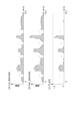
図9(a)~(i)はノイズデータ生成部204、ノイズパラメータ選択部206、および減算処理部207における音声処理のタイミングチャートの一例である。本実施例では説明の簡易化のため、Lchの音声処理について説明するが、Rchの音声処理も同様である。図9(a)~(i)におけるグラフの横軸はすべて時間軸である。 Figures 9(a) to (i) are example timing charts of audio processing in the noise data generation unit 204, the noise parameter selection unit 206, and the subtraction processing unit 207. In this embodiment, for simplicity, audio processing of the Lch will be described, but audio processing of the Rch is similar. The horizontal axis of the graphs in Figures 9(a) to (i) is the time axis.

図9(a)はレンズ制御信号の一例を示す。レンズ制御信号はレンズ制御部102が光学レンズ300に駆動するよう指示する信号である。本実施例では、レンズ制御信号のレベルはHighとLowの2値で表される。レンズ制御信号のレベルがHighである場合、レンズ制御部102は光学レンズ300に駆動するよう指示している状態である。レンズ制御信号のレベルがLowである場合、レンズ制御部102は光学レンズ300に駆動を指示していない状態である。 Figure 9 (a) shows an example of a lens control signal. The lens control signal is a signal that the lens control unit 102 uses to instruct the optical lens 300 to drive. In this embodiment, the level of the lens control signal is expressed as two values, High and Low. When the level of the lens control signal is High, the lens control unit 102 is instructing the optical lens 300 to drive. When the level of the lens control signal is Low, the lens control unit 102 is not instructing the optical lens 300 to drive.

図9(b)はLch_Before[n]の値の一例を示すグラフである。縦軸はLch_Before[n]の値を示す軸である。本実施例では、Lch_Before[n]はFFT部203から出力されるLch_Beforeのうち、光学レンズ300の駆動音を示す信号が特徴的に表れるn番目の周波数ポイントの信号である。なお、本実施例では、n番目の周波数ポイントの信号について説明するが、ほかの周波数に対しても同様に音声処理が実行される。また、信号Xおよび信号Yで示す信号はノイズが含まれる信号である。本実施例では信号Xは短期的なノイズが含まれる信号を示す。信号Yは長期的なノイズが含まれるノイズ信号を示す。 Figure 9 (b) is a graph showing an example of the value of Lch_Before[n]. The vertical axis indicates the value of Lch_Before[n]. In this embodiment, Lch_Before[n] is the signal at the nth frequency point, among the Lch_Before output from the FFT unit 203, at which a signal indicating the driving sound of the optical lens 300 appears characteristically. Note that in this embodiment, the signal at the nth frequency point is described, but audio processing is performed similarly for other frequencies. Furthermore, the signals indicated by signal X and signal Y are signals containing noise. In this embodiment, signal X indicates a signal containing short-term noise. Signal Y indicates a noise signal containing long-term noise.

図9(c)は環境音抽出部2068において抽出された環境音の大きさの一例を示すグラフである。縦軸は取得された環境音から生成された音声信号のレベルを示す。閾値Th1および閾値Th2は、環境音判定部2069において用いられる2つの閾値である。 Figure 9 (c) is a graph showing an example of the volume of the environmental sound extracted by the environmental sound extraction unit 2068. The vertical axis indicates the level of the audio signal generated from the acquired environmental sound. Threshold value Th1 and threshold value Th2 are two threshold values used in the environmental sound determination unit 2069.

図9(d)はNch_Before[n]の値の一例を示すグラフである。Nch_Before[n]は、FFT部203から出力されるNch_Beforeのうち、光学レンズ300の駆動音を示す信号が特徴的に表れるn番目の周波数ポイントの信号である。縦軸は、Nch_Before[n]の値を示す軸である。Nch_Before[n]には、図9(b)における、信号Xおよび信号Yで示したノイズ信号がLch_Beforeよりも特徴的に表れる。 Figure 9 (d) is a graph showing an example of the value of Nch_Before[n]. Nch_Before[n] is the signal at the nth frequency point, among the Nch_Before output from the FFT unit 203, at which the signal indicating the driving sound of the optical lens 300 appears characteristically. The vertical axis indicates the value of Nch_Before[n]. In Nch_Before[n], the noise signals indicated by signals X and Y in Figure 9 (b) appear more characteristically than in Lch_Before.

図9(e)はNdiff[n]の値の一例を示すグラフである。Ndiff[n]は、Nch微分部2064から出力されるNdiffのうち、n番目の周波数ポイントの信号の値を示したものである。縦軸は、Ndiff[n]の値を示す軸である。Nch_Before[n]の所定時間あたりの値の変化量が大きい場合、Ndiff[n]の値が大きくなる。短期雑音検出部2065は、短期的なノイズを検出するために、第一の閾値である閾値Th_Ndiff[n]を持つ。閾値Th_Ndiff[n]は、環境音判定部2069から入力された環境音の大きさを示すデータおよびレンズ制御信号に基づいてレベル1~3の間で変化する。閾値Th_Ndiff[n]の初期値はレベル2とする。また閾値Th_Ndiff[n]のレベルは横の破線で表される。 9(e) is a graph showing an example of the value of Ndiff[n]. Ndiff[n] indicates the value of the signal at the nth frequency point of Ndiff output from the Nch differentiation unit 2064. The vertical axis indicates the value of Ndiff[n]. If the amount of change in the value of Nch_Before[n] per given time is large, the value of Ndiff[n] becomes large. The short-term noise detection unit 2065 has a first threshold value Th_Ndiff[n] to detect short-term noise. The threshold value Th_Ndiff[n] changes between levels 1 to 3 based on the data indicating the volume of the environmental sound input from the environmental sound determination unit 2069 and the lens control signal. The initial value of the threshold value Th_Ndiff[n] is set to level 2. The level of the threshold value Th_Ndiff[n] is indicated by a horizontal dashed line.

図9(f)はNint[n]の値の一例を示すグラフである。本実施例では、Nint[n]は、Nch積分部2066から出力されるNintのうち、n番目の周波数ポイントの信号の値を示したものである。縦軸は、Nint[n]の値を示す軸である。Nch_Before[n]が継続的に大きい場合、Nint[n]の値が大きくなる。長期雑音検出部2067は、長期的なノイズを検出するために、第二の閾値である閾値Th_Nint[n]を持つ。閾値Th_Nint[n]は、環境音判定部2069から入力された環境音の大きさを示すデータおよびレンズ制御信号に基づいてレベル1~3の間で変化する。閾値Th_Nint[n]の初期値はレベル2とする。また閾値Th_Nint[n]のレベルは横の破線で表される。 Figure 9(f) is a graph showing an example of the value of Nint[n]. In this embodiment, Nint[n] indicates the value of the signal at the nth frequency point of Nint output from the Nch integration unit 2066. The vertical axis indicates the value of Nint[n]. If Nch_Before[n] is continuously large, the value of Nint[n] increases. The long-term noise detection unit 2067 has a second threshold, Th_Nint[n], to detect long-term noise. The threshold Th_Nint[n] changes between levels 1 to 3 based on the data indicating the volume of the environmental sound input from the environmental sound determination unit 2069 and the lens control signal. The initial value of the threshold Th_Nint[n] is level 2. The level of the threshold Th_Nint[n] is indicated by a horizontal dashed line.

図9(g)はノイズパラメータ選択部206によって選択されたノイズパラメータの一例を表す。本実施例では、無地部はPL1のノイズパラメータのみが選択されていることを示す。斜線部はPL1およびPL2のノイズパラメータが選択されていることを示す。格子縞部はPL1およびPL3のノイズパラメータが選択されていることを示す。 Figure 9(g) shows an example of noise parameters selected by the noise parameter selection unit 206. In this embodiment, the solid part indicates that only the noise parameter of PL1 has been selected. The diagonal line part indicates that the noise parameters of PL1 and PL2 have been selected. The checkered part indicates that the noise parameters of PL1 and PL3 have been selected.

図9(h)はNL[n]の値の一例を示すグラフである。本実施例では、NL[n]は、ノイズデータ生成部204で生成されるNLのうち、n番目の周波数ポイントの信号の値を示したものである。縦軸は、NL[n]の値を示す軸である。 Figure 9 (h) is a graph showing an example of the value of NL[n]. In this embodiment, NL[n] indicates the signal value of the nth frequency point of NL generated by the noise data generating unit 204. The vertical axis indicates the value of NL[n].

図9(i)はLch_After[n]の値の一例を示すグラフである。本実施例では、Lch_After[n]は、減算処理部207から出力されるLch_Afterのうち、n番目の周波数ポイントの信号の値を示したものである。縦軸は、Lch_After[n]の値を示す軸である。 Figure 9(i) is a graph showing an example of the value of Lch_After[n]. In this embodiment, Lch_After[n] indicates the value of the signal at the nth frequency point of Lch_After output from the subtraction processing unit 207. The vertical axis indicates the value of Lch_After[n].

次にそれぞれの動作に関してタイミングを時刻t701~t709を用いて説明する。 Next, the timing of each operation will be explained using times t701 to t709.

時刻t701において、レンズ制御部102は光学レンズ300およびノイズパラメータ選択部206に、レンズ制御信号としてHighの信号を出力する(図9(a))。時刻t701において、光学レンズ300の筐体内で駆動音が発生する可能性が高いため、短期雑音検出部2065は閾値Th_Ndiff[n]をレベル1に下げる(図9(e))。また時刻t701において、光学レンズ300の筐体内で駆動音が発生する可能性が高いため、長期雑音検出部2067は閾値Th_Nint[n]をレベル1に下げる(図9(f))。 At time t701, the lens control unit 102 outputs a High signal as a lens control signal to the optical lens 300 and the noise parameter selection unit 206 (FIG. 9(a)). At time t701, since there is a high possibility that drive noise will occur within the housing of the optical lens 300, the short-term noise detection unit 2065 lowers the threshold Th_Ndiff[n] to level 1 (FIG. 9(e)). Also at time t701, since there is a high possibility that drive noise will occur within the housing of the optical lens 300, the long-term noise detection unit 2067 lowers the threshold Th_Nint[n] to level 1 (FIG. 9(f)).

時刻t702において、光学レンズ300が駆動し、ギアのかみ合う音などの短期的な駆動音が発生する。ノイズマイク201cがその短期的な駆動音を収音したことにより、Ndiff[n]の値が閾値Th_Ndiff[n]を超える(図9(e))。これに応じて、ノイズパラメータ選択部206はノイズパラメータPL1およびPL2を選択する(図9(g))。ノイズデータ生成部204はNch_Before[n]、およびノイズパラメータPL1およびPL2に基づいてNL[n]を生成する(図9(h))。減算処理部207は、Lch_Before[n]からNL[n]を減算し、Lch_After[n]を出力する(図9(i))。この場合、Lch_After[n]は恒常的なノイズおよび短期的なノイズが低減された音声信号になる。 At time t702, the optical lens 300 is driven, generating short-term drive noise such as the sound of gears meshing. The noise microphone 201c picks up the short-term drive noise, causing the value of Ndiff[n] to exceed the threshold value Th_Ndiff[n] (FIG. 9(e)). In response to this, the noise parameter selection unit 206 selects the noise parameters PL1 and PL2 (FIG. 9(g)). The noise data generation unit 204 generates NL[n] based on Nch_Before[n] and the noise parameters PL1 and PL2 (FIG. 9(h)). The subtraction processing unit 207 subtracts NL[n] from Lch_Before[n] and outputs Lch_After[n] (FIG. 9(i)). In this case, Lch_After[n] becomes an audio signal in which constant noise and short-term noise have been reduced.

時刻t703において、光学レンズ300が連続的な駆動を開始し、光学レンズ300の筐体内において摺動音などの長期的な駆動音が発生する。ノイズマイク201cがその長期的な駆動音を収音したことにより、Nint[n]の値が閾値Th_Nint[n]を超える(図9(f))。これに応じて、ノイズパラメータ選択部206はノイズパラメータPL1およびPL3を選択する(図9(g))。ノイズデータ生成部204はNch_Before[n]、および、ノイズパラメータPL1およびPL3に基づいてNL[n]を生成する(図9(h))。減算処理部207は、Lch_Before[n]からNL[n]を減算し、Lch_After[n]を出力する(図9(i))。この場合、Lch_After[n]は恒常的なノイズおよび長期的なノイズが低減された音声信号になる。 At time t703, the optical lens 300 starts to drive continuously, and long-term drive noise such as sliding noise occurs within the housing of the optical lens 300. The noise microphone 201c picks up the long-term drive noise, and the value of Nint[n] exceeds the threshold value Th_Nint[n] (FIG. 9(f)). In response to this, the noise parameter selection unit 206 selects the noise parameters PL1 and PL3 (FIG. 9(g)). The noise data generation unit 204 generates NL[n] based on Nch_Before[n] and the noise parameters PL1 and PL3 (FIG. 9(h)). The subtraction processing unit 207 subtracts NL[n] from Lch_Before[n] and outputs Lch_After[n] (FIG. 9(i)). In this case, Lch_After[n] becomes an audio signal in which constant noise and long-term noise have been reduced.

時刻t704において、光学レンズ300が連続的な駆動を停止する。ノイズマイク201cがその長期的な駆動音を収音しなくなるため、Nint[n]の値が閾値Th_Nint[n]以下になる(図9(f))。これに応じて、ノイズパラメータ選択部206はノイズパラメータPL1を選択する(図9(g))。ノイズデータ生成部204は、Nch_Before[n]、および、ノイズパラメータPL1に基づいてNL[n]を生成する(図9(h))。減算処理部207は、Lch_Before[n]からNL[n]を減算し、Lch_After[n]を出力する(図9(i))。この場合、Lch_After[n]は恒常的なノイズが低減された音声信号になる。 At time t704, the optical lens 300 stops continuous driving. Because the noise microphone 201c no longer picks up the long-term driving sound, the value of Nint[n] becomes equal to or less than the threshold value Th_Nint[n] (FIG. 9(f)). In response to this, the noise parameter selection unit 206 selects the noise parameter PL1 (FIG. 9(g)). The noise data generation unit 204 generates NL[n] based on Nch_Before[n] and the noise parameter PL1 (FIG. 9(h)). The subtraction processing unit 207 subtracts NL[n] from Lch_Before[n] and outputs Lch_After[n] (FIG. 9(i)). In this case, Lch_After[n] becomes an audio signal with constant noise reduced.

時刻t705においてレンズ制御部102は、光学レンズ300およびノイズパラメータ選択部206にレンズ制御信号としてLowの信号を出力する(図9(a))。この場合、光学レンズ300の筐体内において駆動音が発生する可能性が低くなるため、短期雑音検出部2065は閾値Th_Ndiff[n]をレベル2に上げる(図9(e))。また、この場合、光学レンズ300の筐体内において駆動音が発生する可能性が低くなるため、長期雑音検出部2067は閾値Th_Nint[n]をレベル2に上げる(図9(f))。 At time t705, the lens control unit 102 outputs a Low signal as a lens control signal to the optical lens 300 and the noise parameter selection unit 206 (FIG. 9(a)). In this case, the possibility of drive noise occurring within the housing of the optical lens 300 is low, so the short-term noise detection unit 2065 increases the threshold Th_Ndiff[n] to level 2 (FIG. 9(e)). In addition, in this case, the possibility of drive noise occurring within the housing of the optical lens 300 is low, so the long-term noise detection unit 2067 increases the threshold Th_Nint[n] to level 2 (FIG. 9(f)).

時刻t706において、環境音抽出部2068において抽出された環境音の大きさが閾値Th1を超える。環境音が大きい場合、ユーザには音声信号に含まれるノイズが感じられにくくなるため、短期雑音検出部2065は閾値Th_Ndiff[n]をレベル3に上げる(図9(e))。また、環境音が大きい場合、ユーザには音声信号に含まれるノイズが感じられにくくなるため、長期雑音検出部2067は閾値Th_Nint[n]をレベル3に上げる(図9(f))。 At time t706, the volume of the environmental sound extracted by the environmental sound extraction unit 2068 exceeds the threshold Th1. When the environmental sound is loud, the user is less likely to perceive the noise contained in the audio signal, so the short-term noise detection unit 2065 raises the threshold Th_Ndiff[n] to level 3 (Figure 9(e)). Also, when the environmental sound is loud, the user is less likely to perceive the noise contained in the audio signal, so the long-term noise detection unit 2067 raises the threshold Th_Nint[n] to level 3 (Figure 9(f)).

時刻t707において、レンズ制御部102は光学レンズ300およびノイズパラメータ選択部206に、レンズ制御信号としてHighの信号を出力する(図9(a))。この場合、光学レンズ300の筐体内において駆動音が発生する可能性が高いため、短期雑音検出部2065は閾値Th_Ndiff[n]をレベル2に下げる(図9(e))。また、この場合、光学レンズ300の筐体内において駆動音が発生する可能性が高いため、長期雑音検出部2067は閾値Th_Nint[n]をレベル2に下げる(図9(f))。 At time t707, the lens control unit 102 outputs a High signal as a lens control signal to the optical lens 300 and the noise parameter selection unit 206 (FIG. 9(a)). In this case, since there is a high possibility that drive noise will occur within the housing of the optical lens 300, the short-term noise detection unit 2065 lowers the threshold Th_Ndiff[n] to level 2 (FIG. 9(e)). In addition, since there is a high possibility that drive noise will occur within the housing of the optical lens 300, the long-term noise detection unit 2067 lowers the threshold Th_Nint[n] to level 2 (FIG. 9(f)).

時刻t708において、環境音抽出部2068において抽出された環境音の大きさが閾値Th2を超える。環境音がさらに大きい場合、ユーザには音声信号に含まれるノイズはほとんど感じられないため、ノイズパラメータ選択部206はNchノイズ検出部2061から入力されるデータにかかわらずノイズパラメータPL1のみを選択する。 At time t708, the volume of the environmental sound extracted by the environmental sound extraction unit 2068 exceeds the threshold value Th2. If the environmental sound is even louder, the user will hardly notice any noise contained in the audio signal, and the noise parameter selection unit 206 will select only the noise parameter PL1 regardless of the data input from the Nch noise detection unit 2061.

以上のように、撮像装置100は第2のマイクであるノイズマイク201cを利用してノイズ低減処理を実行することで、ノイズが低減された環境音を記録することができる。 As described above, the imaging device 100 can record environmental sounds with reduced noise by performing noise reduction processing using the second microphone, the noise microphone 201c.

なお、本実施例では、撮像装置100は、光学レンズ300の筐体内で発生する駆動音を低減したが、撮像装置100内で発生する駆動音を低減してもよい。撮像装置100内で発生する駆動音は例えば、基板の音鳴き、および無線電波ノイズである。なお、基板の音鳴きは、例えば基板上のコンデンサに電圧を印加した際に生じる基板のきしみによって発生する音である。 In this embodiment, the imaging device 100 reduces the drive noise generated within the housing of the optical lens 300, but the drive noise generated within the imaging device 100 may also be reduced. The drive noise generated within the imaging device 100 is, for example, the noise of the board and radio wave noise. The noise of the board is, for example, the sound generated by the creaking of the board when a voltage is applied to a capacitor on the board.

なお、環境音判定部2069の閾値Th1および閾値Th2、短期雑音検出部2065の閾値Th_Ndiff[n]、並びに、長期雑音検出部2067の閾値Th_Nint[n]は発生する駆動音と環境音とに基づいて決定される。そのため、撮像装置100は、光学レンズ300の種類および撮像装置100の傾き等によって、これらの閾値をそれぞれ変更してもよい。 The thresholds Th1 and Th2 of the environmental sound determination unit 2069, the threshold Th_Ndiff[n] of the short-term noise detection unit 2065, and the threshold Th_Nint[n] of the long-term noise detection unit 2067 are determined based on the generated drive sound and environmental sound. Therefore, the imaging device 100 may change these thresholds depending on the type of the optical lens 300, the tilt of the imaging device 100, etc.

[第二の実施例]
ここで、図10は第二の実施例における音声入力部104の構成例を示すブロック図である。図3に示す音声入力部104の構成と異なる部分は、減算処理部207およびiFFT部208である。ここで、図3と同様の処理部に関する説明は省略する。
[Second embodiment]
Fig. 10 is a block diagram showing an example of the configuration of the voice input unit 104 in the second embodiment. The parts different from the configuration of the voice input unit 104 shown in Fig. 3 are a subtraction processing unit 207 and an iFFT unit 208. Here, a description of the processing units similar to those in Fig. 3 will be omitted.

iFFT部208aは、FFT部203から入力されたLch_Before、およびRch_Beforeをそれぞれ逆高速フーリエ変換して、周波数領域のデジタル音声信号を時間領域のデジタル音声信号へそれぞれ変換する。また、iFFT部208bは、NL,およびNRをそれぞれ逆高速フーリエ変換して、周波数領域のデジタル音声信号を時間領域のデジタル音声信号へ変換する。 The iFFT unit 208a performs an inverse fast Fourier transform on Lch_Before and Rch_Before input from the FFT unit 203, respectively, to convert the frequency domain digital audio signals into time domain digital audio signals. The iFFT unit 208b also performs an inverse fast Fourier transform on NL and NR, respectively, to convert the frequency domain digital audio signals into time domain digital audio signals.

減算処理部207は、iFFT部208aから入力されたデジタル音声信号からiFFT部208bから入力されたデジタル音声信号を減算する。減算処理部207における演算処理は、デジタル音声信号を時間領域において減算する波形減算方式である。 The subtraction processing unit 207 subtracts the digital audio signal input from the iFFT unit 208b from the digital audio signal input from the iFFT unit 208a. The calculation process in the subtraction processing unit 207 is a waveform subtraction method that subtracts the digital audio signal in the time domain.

なお、波形減算を行う場合、撮像装置100はノイズパラメータとして、デジタル音声信号の位相に関するパラメータも記録してもよい。 When performing waveform subtraction, the imaging device 100 may also record parameters related to the phase of the digital audio signal as noise parameters.

その他の撮像装置100の構成および動作は第一の実施例と同様である。 The rest of the configuration and operation of the imaging device 100 is the same as in the first embodiment.

[その他の実施例]
本発明は、上述の実施例の1以上の機能を実現するプログラムを、ネットワーク又は記録媒体を介してシステム又は装置に供給し、そのシステム又は装置のコンピュータにおける1つ以上のプロセッサがプログラムを読出し実行する処理でも実現可能である。また、1以上の機能を実現する回路(例えば、ASIC)によっても実現可能である。
[Other Examples]
The present invention can also be realized by a process in which a program for implementing one or more of the functions of the above-described embodiments is supplied to a system or device via a network or a recording medium, and one or more processors in a computer of the system or device read and execute the program. The present invention can also be realized by a circuit (e.g., ASIC) that implements one or more of the functions.

なお、本発明は上記実施例そのままに限定されるものではなく、実施段階ではその要旨を逸脱しない範囲で構成要素を変形して具体化できる。また、上記実施例に開示されている複数の構成要素の適宜な組み合わせにより、種々の発明を形成できる。例えば、実施例に示される全構成要素から幾つかの構成要素を削除してもよい。さらに、異なる実施例にわたる構成要素を適宜組み合わせてもよい。 The present invention is not limited to the above-mentioned examples as they are, and in the implementation stage, the components can be modified and embodied without departing from the gist of the invention. In addition, various inventions can be formed by appropriately combining multiple components disclosed in the above-mentioned examples. For example, some components may be deleted from all the components shown in the examples. Furthermore, components from different examples may be appropriately combined.

Claims (12)

環境音を取得するための第一のマイクと、
ノイズ源からの音を取得するための第二のマイクと、
前記第一のマイクからの音声信号をフーリエ変換して第一の音声信号を生成する第一の変換手段と、
前記第二のマイクからの音声信号をフーリエ変換して第二の音声信号を生成する第二の変換手段と、
前記第二の音声信号に基づいて、前記ノイズ源からノイズが発生したことを検出する検出手段と、
前記検出手段によるノイズの検出結果に基づいて、第一の種類のノイズに対応した第一のパラメータと、第二の種類のノイズに対応した第二のパラメータとを含む、複数のパラメータの少なくとも何れかと、前記第二の音声信号と、を用いてノイズデータを生成する生成手段と、
前記第一の音声信号から前記ノイズデータを減算する減算手段と、
前記減算手段からの音声信号を逆フーリエ変換する第三の変換手段と、
を有し、
前記生成手段は、前記ノイズ源からノイズが発生したことが前記検出手段によって検出されなかった場合、前記第二の音声信号と、前記第一のパラメータと、を用いてノイズデータを生成し、
前記生成手段は、前記ノイズ源からノイズが発生したことが前記検出手段によって検出された場合、前記第二の音声信号と、前記第一のパラメータおよび前記第二のパラメータと、を用いてノイズデータを生成することを特徴とする音声処理装置。
a first microphone for acquiring environmental sounds;
a second microphone for acquiring sound from the noise source;
a first conversion means for performing a Fourier transform on the audio signal from the first microphone to generate a first audio signal;
a second conversion means for performing a Fourier transform on the audio signal from the second microphone to generate a second audio signal;
a detection means for detecting that a noise has been generated from the noise source based on the second audio signal;
a generating means for generating noise data using at least one of a plurality of parameters including a first parameter corresponding to a first type of noise and a second parameter corresponding to a second type of noise, based on a result of the noise detection by the detecting means, and the second audio signal;
a subtraction means for subtracting the noise data from the first audio signal;
a third transform means for performing an inverse Fourier transform on the audio signal from the subtraction means;
having
the generating means generates noise data using the second audio signal and the first parameter when the detecting means does not detect that noise has been generated from the noise source;
The generation means generates noise data using the second audio signal, the first parameter, and the second parameter when the detection means detects that noise has been generated from the noise source.
環境音を取得するための第一のマイクと、a first microphone for acquiring environmental sounds;
ノイズ源からの音を取得するための第二のマイクと、a second microphone for acquiring sound from the noise source;
前記第一のマイクからの音声信号をフーリエ変換して第一の音声信号を生成する第一の変換手段と、a first conversion means for performing a Fourier transform on the audio signal from the first microphone to generate a first audio signal;
前記第二のマイクからの音声信号をフーリエ変換して第二の音声信号を生成する第二の変換手段と、a second conversion means for performing a Fourier transform on the audio signal from the second microphone to generate a second audio signal;
前記第二の音声信号に基づいて、前記ノイズ源からノイズが発生したことを検出する検出手段と、a detection means for detecting that a noise has been generated from the noise source based on the second audio signal;
前記検出手段によるノイズの検出結果に基づいて、第一の種類のノイズに対応した第一のパラメータと、第二の種類のノイズに対応した第二のパラメータとを含む、複数のパラメータの少なくとも何れかと、前記第二の音声信号と、を用いてノイズデータを生成する生成手段と、a generating means for generating noise data using at least one of a plurality of parameters including a first parameter corresponding to a first type of noise and a second parameter corresponding to a second type of noise, based on a result of the noise detection by the detecting means, and the second audio signal;
前記第一の音声信号から前記ノイズデータを減算する減算手段と、a subtraction means for subtracting the noise data from the first audio signal;
前記減算手段からの音声信号を逆フーリエ変換する第三の変換手段と、a third transform means for performing an inverse Fourier transform on the audio signal from the subtraction means;
を有し、having
前記第一の種類のノイズは、恒常的なノイズであり、前記第二の種類のノイズは、短期的なノイズ、または長期的なノイズの少なくともいずれかを含むことを特徴とする音声処理装置。10. The audio processing device according to claim 9, wherein the first type of noise is a constant noise, and the second type of noise includes at least one of a short-term noise and a long-term noise.
前記生成手段は、前記ノイズ源からノイズが発生したことが前記検出手段によって検出されなかった場合、前記第二の音声信号と、前記第一のパラメータと、を用いてノイズデータを生成し、
前記生成手段は、前記ノイズ源からノイズが発生したことが前記検出手段によって検出された場合、前記第二の音声信号と、前記第一のパラメータおよび前記第二のパラメータと、を用いてノイズデータを生成することを特徴とする請求項2に記載の音声処理装置。
the generating means generates noise data using the second audio signal and the first parameter when the detecting means does not detect that noise has been generated from the noise source;
The audio processing device according to claim 2, characterized in that the generation means generates noise data using the second audio signal, the first parameter, and the second parameter when the detection means detects that noise has been generated from the noise source.
前記複数のパラメータの情報を記録する記録手段を有することを特徴とする請求項1から3のいずれか1項に記載の音声処理装置。 4. The audio processing device according to claim 1, further comprising a recording unit for recording information on the plurality of parameters. 前記第一のマイクは複数のマイクで構成され、
前記記録手段は前記第一のマイクを構成するマイクごとに前記パラメータを記録することを特徴とする請求項4に記載の音声処理装置。
The first microphone is composed of a plurality of microphones,
5. The audio processing apparatus according to claim 4 , wherein said recording means records said parameters for each microphone constituting said first microphone.
前記検出手段は、所定の周波数の音声信号に基づいて、前記ノイズ源からノイズが発生したか否かを検出することを特徴とする請求項1から5のいずれか1項に記載の音声処理装置。 6. The audio processing device according to claim 1, wherein the detection means detects whether or not noise has been generated from the noise source on the basis of an audio signal of a predetermined frequency. 前記音声処理装置において、前記第一のマイクの上方に環境音を入力するための穴が形成され、前記第二のマイクの上方には環境音を入力するための穴が形成されないことを特徴とする請求項1から6のいずれか1項に記載の音声処理装置。 The audio processing device according to any one of claims 1 to 6, characterized in that in the audio processing device, a hole for inputting environmental sound is formed above the first microphone, and no hole for inputting environmental sound is formed above the second microphone. 前記パラメータは前記第一の音声信号および前記第二の音声信号の振幅の比であることを特徴とする請求項1から7のいずれか1項に記載の音声処理装置。 8. The audio processing apparatus according to claim 1, wherein the parameter is a ratio between the amplitudes of the first audio signal and the second audio signal. 撮像手段をさらに有し、
前記ノイズ源は、前記撮像手段における撮像において駆動する部材であることを特徴とする請求項1から8のいずれか1項に記載の音声処理装置。
The imaging means further includes:
9. The audio processing device according to claim 1, wherein the noise source is a member that is driven during imaging by the imaging means.
環境音を取得するための第一のマイクと、
ノイズ源からの音を取得するための第二のマイクとを有する音声処理装置の制御方法であって、
前記第一のマイクからの音声信号をフーリエ変換して第一の音声信号を生成するステップと、
前記第二のマイクからの音声信号をフーリエ変換して第二の音声信号を生成するステップと、
前記第二の音声信号に基づいて、前記ノイズ源からノイズが発生したか否かを検出する検出ステップと、
前記検出ステップにおけるノイズの検出結果に基づいて、第一の種類のノイズに対応した第一のパラメータと、第二の種類のノイズに対応した第二のパラメータとを含む、複数のパラメータの少なくとも何れかと、前記第二の音声信号と、を用いてノイズデータを生成するステップと、
前記第一の音声信号から前記ノイズデータを減算する減算ステップと、
前記減算ステップによって生成された音声信号を逆フーリエ変換するステップと、
有し、
前記ノイズデータを生成するステップは、前記ノイズ源からノイズが発生したことが前記検出ステップによって検出されなかった場合、前記第二の音声信号と、前記第一のパラメータと、を用いてノイズデータを生成し、
前記ノイズデータを生成するステップは、前記ノイズ源からノイズが発生したことが前記検出ステップによって検出された場合、前記第二の音声信号と、前記第一のパラメータおよび前記第二のパラメータと、を用いてノイズデータを生成することを特徴とする制御方法。
a first microphone for acquiring environmental sounds;
and a second microphone for acquiring a sound from a noise source,
performing a Fourier transform on the audio signal from the first microphone to generate a first audio signal;
performing a Fourier transform on the audio signal from the second microphone to generate a second audio signal;
a detection step of detecting whether or not noise is generated from the noise source based on the second audio signal;
generating noise data using at least one of a plurality of parameters including a first parameter corresponding to a first type of noise and a second parameter corresponding to a second type of noise based on a result of the noise detection in the detection step, and the second audio signal;
a subtraction step of subtracting the noise data from the first audio signal;
performing an inverse Fourier transform on the audio signal produced by the subtraction step;
having
the generating noise data step generates noise data using the second audio signal and the first parameter when the detecting step does not detect that noise is generated from the noise source;
A control method characterized in that the noise data generating step generates noise data using the second audio signal, the first parameter, and the second parameter when the detection step detects that noise has been generated from the noise source .
環境音を取得するための第一のマイクと、a first microphone for acquiring environmental sounds;
ノイズ源からの音を取得するための第二のマイクとを有する音声処理装置の制御方法であって、and a second microphone for acquiring a sound from a noise source,
前記第一のマイクからの音声信号をフーリエ変換して第一の音声信号を生成するステップと、performing a Fourier transform on the audio signal from the first microphone to generate a first audio signal;
前記第二のマイクからの音声信号をフーリエ変換して第二の音声信号を生成するステップと、performing a Fourier transform on the audio signal from the second microphone to generate a second audio signal;
前記第二の音声信号に基づいて、前記ノイズ源からノイズが発生したか否かを検出する検出ステップと、a detection step of detecting whether or not noise is generated from the noise source based on the second audio signal;
前記検出ステップにおけるノイズの検出結果に基づいて、第一の種類のノイズに対応した第一のパラメータと、第二の種類のノイズに対応した第二のパラメータとを含む、複数のパラメータの少なくとも何れかと、前記第二の音声信号と、を用いてノイズデータを生成するステップと、generating noise data using at least one of a plurality of parameters including a first parameter corresponding to a first type of noise and a second parameter corresponding to a second type of noise based on a result of the noise detection in the detection step, and the second audio signal;
前記第一の音声信号から前記ノイズデータを減算する減算ステップと、a subtraction step of subtracting the noise data from the first audio signal;
前記減算ステップによって生成された音声信号を逆フーリエ変換するステップと、performing an inverse Fourier transform on the audio signal produced by the subtraction step;
を有し、having
前記第一の種類のノイズは、恒常的なノイズであり、前記第二の種類のノイズは、短期的なノイズ、または長期的なノイズの少なくともいずれかを含むことを特徴とする音声処理装置。10. The audio processing device according to claim 9, wherein the first type of noise is a constant noise, and the second type of noise includes at least one of a short-term noise and a long-term noise.
コンピュータを請求項1から9のいずれか1項に記載の音声処理装置の各手段として機能させるための、コンピュータが読み取り可能なプログラム。 A computer-readable program for causing a computer to function as each of the means of the voice processing device according to any one of claims 1 to 9 .
JP2020161436A 2020-08-27 2020-09-25 Audio processing device, control method, and program Active JP7566552B2 (en)

Priority Applications (2)

Application Number Priority Date Filing Date Title
JP2020161436A JP7566552B2 (en) 2020-09-25 2020-09-25 Audio processing device, control method, and program
US17/410,358 US11657794B2 (en) 2020-08-27 2021-08-24 Audio processing apparatus for reducing noise using plurality of microphones, control method, and recording medium

Applications Claiming Priority (1)

Application Number Priority Date Filing Date Title
JP2020161436A JP7566552B2 (en) 2020-09-25 2020-09-25 Audio processing device, control method, and program

Publications (2)

Publication Number Publication Date
JP2022054316A JP2022054316A (en) 2022-04-06
JP7566552B2 true JP7566552B2 (en) 2024-10-15

Family

ID=80994553

Family Applications (1)

Application Number Title Priority Date Filing Date
JP2020161436A Active JP7566552B2 (en) 2020-08-27 2020-09-25 Audio processing device, control method, and program

Country Status (1)

Country Link
JP (1) JP7566552B2 (en)

Citations (4)

* Cited by examiner, † Cited by third party
Publication number Priority date Publication date Assignee Title
JP2005308771A (en) 2004-04-16 2005-11-04 Nec Corp Noise-filtering method, noise eliminator, system, and program for noise filtering
JP2006279757A (en) 2005-03-30 2006-10-12 Casio Comput Co Ltd Imaging apparatus, audio recording method, and program
JP2013110629A (en) 2011-11-22 2013-06-06 Sony Corp Imaging apparatus and sound collection method
JP2013182185A (en) 2012-03-02 2013-09-12 Canon Inc Sound processor

Patent Citations (4)

* Cited by examiner, † Cited by third party
Publication number Priority date Publication date Assignee Title
JP2005308771A (en) 2004-04-16 2005-11-04 Nec Corp Noise-filtering method, noise eliminator, system, and program for noise filtering
JP2006279757A (en) 2005-03-30 2006-10-12 Casio Comput Co Ltd Imaging apparatus, audio recording method, and program
JP2013110629A (en) 2011-11-22 2013-06-06 Sony Corp Imaging apparatus and sound collection method
JP2013182185A (en) 2012-03-02 2013-09-12 Canon Inc Sound processor

Also Published As

Publication number Publication date
JP2022054316A (en) 2022-04-06

Similar Documents

Publication Publication Date Title
CN101686323A (en) Imaging apparatus and mode appropriateness evaluating method
US11657794B2 (en) Audio processing apparatus for reducing noise using plurality of microphones, control method, and recording medium
JP6637926B2 (en) Voice processing device and control method thereof
JP5020845B2 (en) Audio processing device
JP4639902B2 (en) Imaging apparatus, audio recording method, and program
JP7665304B2 (en) Audio processing device, control method, and program
JP7566552B2 (en) Audio processing device, control method, and program
JP7580996B2 (en) Audio processing device, control method, and program
JP7686439B2 (en) Audio processing device, control method, and program
JP5063489B2 (en) Judgment device, electronic apparatus including the same, and judgment method
JP7604154B2 (en) Audio processing device, control method, and program
JP7608092B2 (en) Audio processing device, control method, and program
JP7725236B2 (en) Audio processing device, control method, and program
JP7725244B2 (en) Audio processing device and control method thereof
US11729548B2 (en) Audio processing apparatus, control method, and storage medium, each for performing noise reduction using audio signals input from plurality of microphones
JP2022054317A (en) Sound processor, control method, and program
JP2000278581A (en) Video camera
JP7757079B2 (en) Audio processing device, control method, and program
JP6985821B2 (en) Speech processing device and its control method
JP6929137B2 (en) Speech processing device and its control method
JP2003233947A (en) Sound recording device
JP6931296B2 (en) Speech processing device and its control method
JP6877246B2 (en) Speech processing device and its control method
JP6886352B2 (en) Speech processing device and its control method
JP2023026918A (en) Voice processing unit, control method of voice processing unit, and program

Legal Events

Date Code Title Description
A621 Written request for application examination

Free format text: JAPANESE INTERMEDIATE CODE: A621

Effective date: 20230912

RD01 Notification of change of attorney

Free format text: JAPANESE INTERMEDIATE CODE: A7421

Effective date: 20231213

A977 Report on retrieval

Free format text: JAPANESE INTERMEDIATE CODE: A971007

Effective date: 20240628

A131 Notification of reasons for refusal

Free format text: JAPANESE INTERMEDIATE CODE: A131

Effective date: 20240702

A521 Request for written amendment filed

Free format text: JAPANESE INTERMEDIATE CODE: A523

Effective date: 20240821

TRDD Decision of grant or rejection written
A01 Written decision to grant a patent or to grant a registration (utility model)

Free format text: JAPANESE INTERMEDIATE CODE: A01

Effective date: 20240903

A61 First payment of annual fees (during grant procedure)

Free format text: JAPANESE INTERMEDIATE CODE: A61

Effective date: 20241002

R150 Certificate of patent or registration of utility model

Ref document number: 7566552

Country of ref document: JP

Free format text: JAPANESE INTERMEDIATE CODE: R150