JP7565521B2 - Ion-permeable membrane and method for producing same - Google Patents
Ion-permeable membrane and method for producing same Download PDFInfo
- Publication number
- JP7565521B2 JP7565521B2 JP2021073998A JP2021073998A JP7565521B2 JP 7565521 B2 JP7565521 B2 JP 7565521B2 JP 2021073998 A JP2021073998 A JP 2021073998A JP 2021073998 A JP2021073998 A JP 2021073998A JP 7565521 B2 JP7565521 B2 JP 7565521B2
- Authority
- JP
- Japan
- Prior art keywords
- ion
- permeable membrane
- water
- conductor particles
- fiber substrate
- Prior art date
- Legal status (The legal status is an assumption and is not a legal conclusion. Google has not performed a legal analysis and makes no representation as to the accuracy of the status listed.)
- Active
Links
Images





Classifications
-
- Y—GENERAL TAGGING OF NEW TECHNOLOGICAL DEVELOPMENTS; GENERAL TAGGING OF CROSS-SECTIONAL TECHNOLOGIES SPANNING OVER SEVERAL SECTIONS OF THE IPC; TECHNICAL SUBJECTS COVERED BY FORMER USPC CROSS-REFERENCE ART COLLECTIONS [XRACs] AND DIGESTS
- Y02—TECHNOLOGIES OR APPLICATIONS FOR MITIGATION OR ADAPTATION AGAINST CLIMATE CHANGE
- Y02E—REDUCTION OF GREENHOUSE GAS [GHG] EMISSIONS, RELATED TO ENERGY GENERATION, TRANSMISSION OR DISTRIBUTION
- Y02E60/00—Enabling technologies; Technologies with a potential or indirect contribution to GHG emissions mitigation
- Y02E60/10—Energy storage using batteries
Landscapes
- Electrolytic Production Of Non-Metals, Compounds, Apparatuses Therefor (AREA)
- Separation Using Semi-Permeable Membranes (AREA)
Description
本発明はイオン透過膜およびその製造方法に関する。 The present invention relates to an ion-permeable membrane and a method for producing the same.
レアメタルは、携帯電話・スマートフォン、家電品、および自動車部品など数多くのハイテク機器において必要不可欠であるものの、安定的な資源確保が難しいことから、レアメタル回収技術に注目が集まりつつある。また、今まで産業廃棄していた廃液に処理工程を加えることで、廃棄することなく再利用する技術も重要視されている。レアメタル回収技術および廃液の再利用技術には、イオン交換樹脂及び/又は吸着剤を用いることが主流であるが、近年、循環型社会構築のために環境に配慮した回収・再利用プロセスとして様々な機能膜を用いる分離技術活用が有効的と考えられつつある。 Rare metals are essential for many high-tech devices, such as mobile phones, smartphones, home appliances, and automobile parts. However, since it is difficult to secure a stable supply of rare metals, attention is being focused on rare metal recovery technology. In addition, technology that reuses waste liquids that have previously been industrially disposed of without disposal by adding a treatment process is also gaining importance. Ion exchange resins and/or adsorbents are mainly used in rare metal recovery technology and waste liquid reuse technology, but in recent years, the use of separation technology using various functional membranes as an environmentally friendly recovery and reuse process for building a recycling-oriented society is being considered effective.
近年、リチウムイオン電池の原材料として、リチウム(Li)の産業上における重要性が高まっている。特に電気自動車(EV)用途でLiイオン電池が採用されるようになり、その原材料として大量のLiが必要とされつつある。このLiは鉱石、または水分蒸発量の多い乾燥した地域の塩湖などから採取することも可能であるが、海水中に非常に多く含まれていることも知られており、地球上の全海水中に含まれるLiの総量は、地上埋蔵量よりはるかに多いことが知られている。また、他のレアメタルと同様に、安定的な資源確保の目的で、産業廃棄していたLiイオン電池からLiを回収する検討も進められつつある。 In recent years, the industrial importance of lithium (Li) as a raw material for lithium-ion batteries has been increasing. In particular, Li-ion batteries have come to be adopted for electric vehicle (EV) applications, and large amounts of Li are being required as a raw material. This Li can be extracted from ores or salt lakes in dry regions with high water evaporation rates, but it is also known that seawater contains very large amounts of Li, and the total amount of Li contained in all seawater on Earth is known to be far greater than the total amount of Li buried on land. As with other rare metals, research is also underway to recover Li from Li-ion batteries that have been discarded from industry in order to ensure a stable supply of resources.
しかしながら、Liは、海水1リットル当たり約0.2mgしか含まれていない。また、産業廃棄していたLiイオン電池には、Li以外にニッケル(Ni)またはコバルト(Co)などの化合物も多く含まれている。そのため、Liは、海水およびLiイオン電池から効率よく回収することが難しい金属材料といえる。 However, seawater contains only about 0.2 mg of Li per liter. Industrially discarded Li-ion batteries also contain large amounts of nickel (Ni) or cobalt (Co) compounds in addition to Li. For this reason, Li is a metal material that is difficult to efficiently recover from seawater and Li-ion batteries.
こうした背景の下、特許文献1では、Liを選択的に透過させる選択透過膜を用いて、Liイオンを含む原液から効率的にLiのみ回収することを試みている。特許文献1では、Liイオンを選択的に透過させる選択透過膜が、Liを含む無機化合物の焼結体であり、焼結体の大きさとして5cm角程度のものを面内方向で接合して一体化し、実質的に大面積とした選択透過膜が開示されている。
In light of this background,
しかしながら、特許文献1に開示されるような従来技術では、焼結体が非常にもろいために、大量の原液を高速に処理する場合、高い圧力がかかって割れてしまうなど、機械的強度が不十分であり、また、イオン透過機能も不十分であることもわかった。
However, in the conventional technology disclosed in
本発明は、上記問題を解決するものであって、十分な機械的強度およびイオン透過機能を示すイオン透過膜およびその製造方法を提供することを目的とする。 The present invention aims to solve the above problems and provide an ion-permeable membrane that exhibits sufficient mechanical strength and ion permeability, and a method for manufacturing the same.
本発明の態様1は、イオン伝導体粒子と、繊維基材と、水溶性高分子化合物を含む充填材と、を含むイオン透過膜であって、
前記イオン伝導体粒子は、前記繊維基材の内部に埋め込まれた部分と、前記繊維基材から露出した部分を有し、
前記イオン透過膜の厚さ方向において、前記露出した部分が、前記イオン透過膜の一方の表面から、前記一方の表面と対向する表面まで連結しており、
前記水溶性高分子化合物は耐水性を有する、イオン透過膜である。
A first aspect of the present invention is an ion-permeable membrane comprising ion conductor particles, a fiber substrate, and a filler containing a water-soluble polymer compound,
the ion conductor particles have a portion embedded in the fiber substrate and a portion exposed from the fiber substrate,
the exposed portion is connected from one surface of the ion-permeable membrane to a surface opposite to the one surface in a thickness direction of the ion-permeable membrane,
The water-soluble polymer compound is a water-resistant, ion-permeable membrane.
本発明の態様2は、前記イオン伝導体粒子がリチウム(Li)を含む無機化合物である、態様1に記載のイオン透過膜である。
本発明の態様3は、前記繊維基材が疎水性である、態様1または2に記載のイオン透過膜である。
本発明の態様4は、前記繊維基材が含フッ素ポリマーを含み、
前記含フッ素ポリマーが、モノマー単位としてフッ化ビニリデン単位、テトラフルオロエチレン単位およびクロロトリフルオロエチレン単位からなる群より選択されるいずれか1つ以上を含む、態様1~3のいずれか1つに記載のイオン透過膜である。
A fourth aspect of the present invention is a fiber substrate comprising a fluoropolymer,
The ion-permeable membrane according to any one of
本発明の態様5は、
イオン伝導体粒子と繊維基材用材料とを共に紡糸し、紡糸膜を得ることと、
前記紡糸膜を水溶性高分子化合物の溶液に浸漬させ、乾燥させることと、
前記水溶性高分子化合物に耐水化処理することと、を含む態様1~4のいずれか1つに記載のイオン透過膜の製造方法である。
Aspect 5 of the present invention is
Co-spinning the ion conductor particles and a fiber substrate material to obtain a spun membrane;
immersing the spun membrane in a solution of a water-soluble polymer compound and drying it;
and subjecting the water-soluble polymer compound to a water-resistant treatment.
本発明の実施形態によれば、十分な機械的強度およびイオン透過機能を示すイオン透過膜およびその製造方法を提供することが可能である。 According to an embodiment of the present invention, it is possible to provide an ion-permeable membrane that exhibits sufficient mechanical strength and ion permeability, and a method for manufacturing the same.
以下本発明の実施形態に係るイオン透過膜について、図面を参照しながら説明する。なお、以下の説明においては、同じ構成部分には同じ符号を付して、適宜説明を省略している。また、本明細書において、「平均繊維径」および「平均粒子径」は、それぞれメジアン径を意味する。 The ion-permeable membrane according to an embodiment of the present invention will be described below with reference to the drawings. In the following description, the same components are given the same reference numerals and the description will be omitted as appropriate. In this specification, the terms "average fiber diameter" and "average particle diameter" each refer to the median diameter.
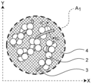
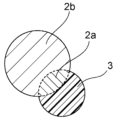
図1Aは、本発明の実施形態に係るイオン透過膜1の模式図を示しており、図1Bは、図1Aのうち、破線で囲ったA1部分の拡大図を示しており、図1Cは、図1Bに示すIC-IC線断面図を示しており、図1Dは、図1Aのうち、破線で囲ったB1部分の拡大図を示している。
FIG. 1A shows a schematic diagram of an ion-
イオン透過膜1は、図1Bに示すように、イオン伝導体粒子2と、繊維基材3(ドットパターンで示される)と、水溶性高分子化合物を含む充填材4(網目パターンで示される)とを含んでいる。イオン透過膜1は、イオン伝導体粒子の焼結体である従来技術と比較して、イオン伝導体粒子2のみではなく繊維基材3および充填材4を含むことにより柔軟性を示すようになり、割れることなく大量の原液を高速に処理できる。図1Cに示すように、イオン伝導体粒子2は、繊維基材3の内部に埋め込まれた部分(以下、「埋込部」と称することがある)2a(図1Cの破線で囲まれた部分)と、繊維基材3から露出した部分(以下、「露出部」と称することがある)2bとを有する。図1Cに示すように、繊維基材3は、イオン伝導体粒子2との接合部分において、埋込部2aの分だけ凹んだ形状をとる。露出部2bによりイオン透過膜1のイオン透過機能を付与しつつ、埋込部2aによりイオン伝導体粒子2を繊維基材3に固定することができ、例えば大量の原液を高速に処理する場合でもイオン伝導体粒子2の脱落を抑制できる。
As shown in FIG. 1B, the ion-
イオン透過膜1は、図1Dに示すように、イオン透過膜1の厚さ方向Zにおいて、イオン透過膜1の上面1aから下面1bまで、複数のイオン伝導体粒子2の露出部2b同士が連結している(以下、この連結した部分を「接続部1c」と称する)。この接続部1cが、図1Dの一点鎖線で示すようなイオン伝導パスとなり、イオン透過膜1がイオン透過機能を有するようになる。また、イオン透過膜1は繊維基材3を含むことにより、イオン透過膜1の上面1aおよび下面1bに凹凸を効果的に形成でき、イオン透過膜で処理する対象との接触面積(当該対象が海水等の液体であれば接液面積)を向上させることができ、イオンの移動を促進できる。
As shown in FIG. 1D, in the thickness direction Z of the ion
また、図1Bおよび1Dに示すように、イオン透過膜1は、イオン伝導体粒子2および繊維基材3以外の部分に、(耐水性を有する水溶性高分子化合物を含む)充填材4を含む。これにより、処理の対象(例えば海水など)が、そのままイオン透過膜を透過してしまう現象(以下、「クロスオーバー現象」ともいう)が発生しにくくなる。これは耐水性を有する水溶性高分子化合物が処理対象を効率よくはじき、そのままイオン透過膜を透過することを抑制するためと考えられる。
以上のような構成をとることにより、イオン透過膜1は十分な機械的強度およびイオン透過機能を示すようになる。
1B and 1D, the ion-
By adopting the above-mentioned configuration, the ion-
図1Bおよび1Dに示すように、複数の繊維基材3は、繊維基材3同士互いに接触していることが好ましく、この接触部分において、繊維基材3同士が融着していることがより好ましい。これにより、イオン透過膜1の機械的強度、特に破断伸び率が向上し、割れ等を効果的に抑制できる。
As shown in Figures 1B and 1D, it is preferable that the
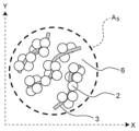
図2Aは、本発明の実施形態に係るイオン透過膜1の製造過程における紡糸膜5の模式図を示しており、図2Bは、図2Aのうち、破線で囲ったA5部分の拡大図を示しており、図2Cは、図2Aのうち、破線で囲ったB5部分の拡大図を示している。
FIG. 2A shows a schematic diagram of a spun membrane 5 in a manufacturing process of an ion-
図2Bおよび図2Cに示すように、後述する紡糸膜5の状態(後述するイオン透過膜1の製造方法における(a)後、(b)前の状態)では、充填材4を含んでおらず、空隙6が大きく且つ多数存在する。このような状態では、紡糸膜5の上面5aから下面5bまで空隙6が連通しやすくなり、クロスオーバー現象が発生しやすくなる。
As shown in Figures 2B and 2C, in the state of the spun membrane 5 described later (the state after (a) and before (b) in the manufacturing method of the ion-
イオン伝導体粒子2は、例えば、リチウムイオン伝導体である窒化リチウム(Li3N)、Li10GeP2S12、(Lax,Liy)TiOz、(ここで、x=2/3-a、y=3a―2b、z=3-b、0<a≦1/6、0≦b≦0.06、y>0)、Li置換型NASICON(Na Super Ionic Conductor)型結晶であるLi1+x+yAlx(Ti,Ge)2-xSiyP3-yO12(ここで、0≦x≦0.6、0≦y≦0.6)などLiを含むもの(例えば無機化合物等)を用いることができる。これらの材料は、いずれも10-4~10-3Scm-1以上の高いLiイオン伝導率を示す。なお、イオン伝導体粒子2は、イオン伝導性を有していれば上記の材料に限定されるものではない。なお、イオン伝導率が10-7Scm-1以上の場合、イオン伝導性を有すると判断する。
The
イオン伝導体粒子2の平均粒子径は、50nm以上500μm以下とすることが、イオン伝導体粒子2が埋込部2aと露出部2bとを有する構成を実現する上で好ましい。
It is preferable that the average particle diameter of the
イオン伝導体粒子2の、イオン伝導体粒子2、繊維基材3および充填材4の合計体積に対する割合は、30体積%以上にしておくことが好ましい。この範囲にしておくことで、イオン透過膜において、イオン伝導体粒子2が互いに接触しやすくなり、接続部1cが形成されやすくなる。より好ましくは35体積%以上であり、さらに好ましくは40体積%以上である。
また、上記割合は、90体積%以下にしておくことが好ましい。これにより、繊維基材3および充填材4が一定以上の体積を占めることとなり、十分な破断伸び率を確保しやすくなるとともに、イオン伝導体粒子の埋込部2aを確保しやすくなり、イオン伝導体粒子の脱落を抑制できる。より好ましくは85体積%以下であり、さらに好ましくは80体積%以下である。
The ratio of the
The ratio is preferably 90% by volume or less. This allows the
繊維基材3は、柔軟性を有することが好ましい。これにより、イオン透過膜1の破断伸び率が向上し得る。なお、JIS K7161の試験方法により測定される破断伸び率が1%以上の場合、材料が柔軟性を有すると判断する。
繊維基材3は疎水性を有することが好ましい。疎水性を有することで、イオン透過膜1による処理の対象(例えば海水など)が、そのままイオン透過膜1を透過してしまう現象(以下、「クロスオーバー現象」ともいう)を効果的に抑制することができる。例えば、ASTM D-570の試験方法により測定される吸水率が0.1%以下の場合、材料が疎水性を有すると判断する。
It is preferable that the
It is preferable that the
繊維基材3は、有機高分子化合物を含み得る。繊維基材3は有機高分子化合物を50質量%以上含むことが好ましい。これにより、繊維基材3は、柔軟性を有しやすくなる。より好ましくは、繊維基材3が、有機高分子化合物を75質量%以上含むことであり、さらに好ましくは、繊維基材3が、有機高分子化合物からなることである。繊維基材3は、有機高分子化合物として疎水性高分子化合物および/または非水溶性高分子化合物を含み得る。繊維基材3は、例えば、モノマー単位としてフッ化ビニリデン単位、テトラフルオロエチレン単位、およびクロロトリフルオロエチレン単位からなる群より選択されるいずれか1つ以上を含む含フッ素ポリマーを含んでいることが好ましく、繊維基材3は当該含フッ素ポリマーからなることがより好ましい。
The
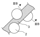
図3Aは、本発明の実施形態に係るイオン透過膜1において、繊維基材3の平均繊維径がイオン伝導体粒子2の平均粒子径の0.8倍である場合の、繊維1本を拡大した模式図であり、図3Bは、図3Aに示す繊維のIIIB-IIIB線断面図である。図3Bに示すように、イオン伝導体粒子2の埋込部2aが十分に確保できているため、イオン伝導体粒子2が繊維基材3にしっかりと固定でき、かつ、イオン伝導体粒子2の露出部2bも十分に大きく確保できている。そのことから、イオン伝導体粒子2が繊維基材3の表面にも十分露出した状態で担持できているため、イオン伝導体粒子2の脱落を抑制しつつ、イオンの移動を促進させることができる。なお、イオン伝導体粒子2のうち埋込部2aが体積比で5%以上であれば、埋込部2aが十分に確保できているといえる。また、イオン伝導体粒子2のうち露出部2bが体積比で50%以上であれば、露出部2bが十分に確保できているといえる。
Figure 3A is a schematic diagram of an enlarged fiber in an ion-
図3Cは、本発明の実施形態に係るイオン透過膜1において、繊維基材3の平均繊維径がイオン伝導体粒子2の平均粒子径よりも大きい場合の、繊維1本を拡大した模式図であり、図3Dは、図3Cに示す繊維のIIID-IIID線断面図である。図3Dに示すように、イオン伝導体粒子2の埋込部2aが十分に確保できているため、イオン伝導体粒子2が繊維基材3にしっかりと固定でき、その結果イオン伝導体粒子2の脱落を抑制できる。しかしながら、イオン伝導体粒子2の露出部2bが小さいため、イオン透過機能としては図3Aおよび図3Bの場合と比較してイオンの移動を促進することはできない。
Figure 3C is a schematic diagram showing an enlarged view of one fiber in an ion-
図3Eは、本発明の実施形態に係るイオン透過膜1において、繊維基材3の平均繊維径がイオン伝導体粒子2の平均粒子径の0.2倍以下である場合の、繊維基材の繊維1本を拡大した模式図であり、図3Fは、図3Eに示す繊維のIIIF-IIIF線断面図である。図3Fに示すように、イオン伝導体粒子2の埋込部2aが、ほとんど確保できていないため、図3A~図3Dの場合と比較してイオン伝導体粒子2が脱落しやすくなる。
Figure 3E is a schematic diagram showing an enlarged view of one fiber of a fiber substrate in an ion
以上より、繊維基材3の平均繊維径をAナノメートル(nm)、イオン伝導体粒子2の平均粒子径をBナノメートル(nm)としたとき、B×0.2<A<Bを満たすことが好ましい。より好ましくは、B×0.2<A<B×0.75、さらに好ましくは、B×0.2<A<B×0.5を満たすことである。
From the above, when the average fiber diameter of the
繊維基材3の平均長さは、繊維基材の平均繊維径の100倍以上であることが好ましい。これにより、イオン透過膜1の機械的強度、特に破断伸び率をより向上させることができる。
The average length of the
繊維基材3の、イオン伝導体粒子2、繊維基材3および充填材4の合計体積に対する割合は、5体積%以上にしておくことが好ましい。これにより、十分な破断伸び率を確保しやすくなるとともに、イオン伝導体粒子の埋込部2aを確保しやすくなり、イオン伝導体粒子の脱落を抑制できる。より好ましくは10体積%以上であり、さらに好ましくは15体積%以上である。
上記割合は、65体積%以下にしておくことが好ましい。この範囲にしておくことで、イオン透過膜において、イオン伝導体粒子2が互いに接触しやすくなり、接続部1cが形成されやすくなる。より好ましくは60体積%以下であり、さらに好ましくは55体積%以下である。
The ratio of the
The above ratio is preferably 65% by volume or less. By keeping it in this range, the
充填材4は、水溶性高分子化合物を含む。充填材4は、水溶性高分子化合物を50質量%以上含むことが好ましい。より好ましくは、充填材4が、水溶性高分子化合物を75質量%以上含むことであり、さらに好ましくは、充填材4が、水溶性高分子化合物からなることである。水溶性高分子化合物としては、例えばポリビニルアルコール及びその誘導体、澱粉及びその誘導体、ヒドロキシメチルセルロース、ヒドロキシエチルセルロース、ヒドロキシプロピルセルロース、メチルセルロース、エチルセルロース等のセルロース誘導体、ポリアクリル酸ナトリウム、ポリビニルピロリドン、カゼイン、ゼラチン及びそれらの誘導体などからなる群より選択されるいずれか1つ以上を含むことが好ましいが、水溶性高分子化合物であれば、これに限らない。
The
充填材4中の水溶性高分子化合物は耐水性を有する。ここで耐水性を有するとは、実質的に水に溶出しないことを意味する。水溶性高分子化合物が耐水性を有するとき、例えば初期重量に対して100倍重量の水で30分煮沸した前後の重量比である不溶化率が70%以上であり得る。水溶性高分子化合物は耐水化処理されることにより、耐水性を有するようになる。耐水化処理としては、水溶性高分子化合物同士を連結し、物理的、化学的性質を変化させる反応を行うことが挙げられ、例えば水溶性高分子化合物の種類に応じて架橋剤(橋かけ剤)を添加すること、加熱処理または放射線照射等の処理を行うことで、耐水化処理された水溶性高分子化合物が得られる。架橋剤としては、イソシアネート系架橋剤、エポキシ系架橋剤、オキサゾリン系架橋剤、アジリジン系架橋剤および金属キレート系架橋剤からなる群より選択されるいずれか1つ以上を含むことが好ましいが、耐水化可能な架橋剤であれば、これに限らない。
The water-soluble polymer compound in the
充填材4は、柔軟性を有することが好ましい。これにより、イオン透過膜1の破断伸び率が向上し得る。
It is preferable that the
充填材4の、イオン伝導体粒子2、繊維基材3および充填材4の合計体積に対する割合は、30体積%以下にしておくことが好ましい。この範囲にしておくことで、イオン伝導体粒子2の割合が多くなり、イオン透過膜1において、イオン伝導体粒子2が互いに接触しやすくなり、接続部1cが形成されやすくなる。より好ましくは25体積%以下であり、さらに好ましくは20体積%以下である。
また、上記割合は、5体積%以上にしておくことが好ましい。これにより、充填材4が一定以上の体積を占めることとなり、十分な破断伸び率を確保しやすくなるとともに、クロスオーバー率を低減できる。より好ましくは10体積%以上である。
The ratio of the
The ratio is preferably 5% by volume or more. This allows the
本発明の実施形態に係るイオン透過膜1の膜厚は薄い程、イオンの移動を促進できるが、一方で耐久性は低下するため、イオン透過膜1の使用条件によって最適な範囲に設計され得る。また、イオン透過膜1は、本発明の目的が達成される範囲内で、イオン伝導体粒子2、繊維基材3および充填材4以外の他の部材を含んでいてもよい。
The thinner the thickness of the ion-
本発明の実施形態に係るイオン透過膜の空隙率は、19.0%以下が好ましい。19.0%以下とすることで、クロスオーバー現象を効果的に抑制することができる。また、イオン伝導パスである接続部1cを形成しやすくなる。より好ましくは15.0%以下である。なお、空隙率は、イオン透過膜1がイオン伝導体粒子2、繊維基材3および充填材4からなる場合、以下の式(1)により算出できる。
空隙率(%) = 1-Wa/(Va×(Dip×rip+Df×rf+Dwr×rwr))×100 ・・・(1)
ここで、Waは、イオン透過膜1の重量(g)であり、Vaはイオン透過膜1の体積(cm3)であり、Dipはイオン伝導体粒子2の密度(g/cm3)であり、ripはイオン伝導体粒子2、繊維基材3および充填材4の合計体積に対するイオン伝導体粒子2の体積比(%)であり、Dfは繊維基材3の密度(g/cm3)であり、rfはイオン伝導体粒子2、繊維基材3および充填材4の合計体積に対する繊維基材3の体積比(%)であり、Dwrは充填材4の密度(g/cm3)であり、rwrはイオン伝導体粒子2、繊維基材3および充填材4の合計体積に対する充填材4の体積比(%)である。
The porosity of the ion-permeable membrane according to the embodiment of the present invention is preferably 19.0% or less. By setting the porosity to 19.0% or less, the crossover phenomenon can be effectively suppressed. In addition, it is easier to form the
Porosity (%) = 1-Wa/(Va×( Dip × rip + Df × rf + Dwr × rwr ))×100...(1)
Here, Wa is the weight (g) of the ion
本発明の実施形態に係るイオン透過膜1は、十分な機械的強度を示し、大量の原液の高速処理が可能である。具体的には、後述する粒子脱落率が0重量%、破断伸び率が15%以上という機械的強度を示し、これにより、大量の原液を高速に処理したとしても耐久することができ、例えば膜が圧力によって破壊したり、イオン透過機能が消失するといった不具合も抑制することができる。
The ion-
本発明の実施形態に係るイオン透過膜1は、十分なイオン透過機能を有する。具体的には、例えば、Liイオン伝導体粒子を用いたイオン透過膜1の場合、後述するイオン回収率、イオン移動速度およびクロスオーバー率について、Liイオンのイオン回収率を10.0%以上、Liイオンのイオン移動速度を0.2mg/hr以上且つクロスオーバー率を0.01%未満にすることができる。
上記は、Liイオン伝導体粒子を用いたイオン透過膜の場合を例示しているが、Liイオン以外のイオン伝導体粒子を用いた場合も同様である。例えば、Naイオン伝導体粒子を用いたイオン透過膜の場合、Naイオンのイオン回収率を10.0%以上、Naイオンのイオン移動速度を0.2mg/hr以上且つクロスオーバー率を0.01%未満にすることができる。
The ion
The above is an example of an ion-permeable membrane using Li ion conductor particles, but the same applies to cases where ion conductor particles other than Li ions are used. For example, in the case of an ion-permeable membrane using Na ion conductor particles, the ion recovery rate of Na ions can be 10.0% or more, the ion migration rate of Na ions can be 0.2 mg/hr or more, and the crossover rate can be less than 0.01%.
本発明の実施形態に係るイオン透過膜1は、単体でイオン透過に使用されてもよいし、電気透析装置などのイオン透過装置に組み込まれても良い。イオン透過膜1がイオン透過装置に組み込まれていると、大量の原液を高速に処理する場合に、高い圧力がかかっても破壊されにくく、かつ、イオン伝導体粒子2の脱落が大幅に抑制された、イオン透過装置およびイオン透過方法を実現することができる。
The ion
イオン透過方法については、所望のイオンを含む水などの溶媒、土壌、および、産業廃棄物などにイオン透過膜1を接触させることができればよい。
The ion permeation method requires that the ion
イオン透過膜1が接触させられる土壌および産業廃棄物などは、水などの溶媒で濡れていることが望ましい。イオン透過膜が水などの溶媒を介して接触させられると、イオン透過が効率的に行われる。そして、水などの溶媒、土壌、および産業廃棄物などに含まれる所望のイオンを脱離するために、超音波処理、またはマイクロ/ナノバブル発生装置によるバブリング処理などが必要に応じて併用されると、イオン透過がより効率的に行われる。
The soil, industrial waste, etc., with which the ion-
次に、本発明の実施形態に係るイオン透過膜1の製造方法について説明する。
本発明の実施形態に係るイオン透過膜1の製造方法は、
(a)イオン伝導体粒子と繊維基材用材料とを共に紡糸し、紡糸膜を得ることと、
(b)前記紡糸膜を水溶性高分子化合物の溶液に浸漬させ、乾燥させることと、
(c)前記水溶性高分子化合物に耐水化処理することと、を含む。
上記(a)~(c)について、以下に説明する。
Next, a method for producing the ion
A method for producing the ion
(a) co-spinning ion conductor particles and a fiber substrate material to obtain a spun membrane;
(b) immersing the spun membrane in a solution of a water-soluble polymer compound and drying it;
(c) subjecting the water-soluble polymer compound to a water-resistant treatment.
The above items (a) to (c) will be explained below.
(a)紡糸膜を得ること
まず、イオン伝導体粒子2と繊維基材3の原料(以下「繊維基材3用材料」とも称し、例えば有機高分子化合物)を混合する。この際、混錬機を用いて溶媒に分散することもできるが、熱可塑性樹脂の場合には、粉体混合機によるドライブレンドを行うこともできる。
(a) Obtaining a spun membrane First, the
上記のように混合した後、繊維基材3用材料が液体の場合には、通常の電界紡糸法のような湿式紡糸法によって、イオン伝導体粒子2と繊維基材3用材料を共に紡糸することができる。
電界紡糸法により紡糸する場合、繊維基材3用材料の重量固形分濃度により、繊維基材3の繊維径を調整することができる。すなわち、繊維基材3用材料の重量固形分率を増大させることにより繊維基材3の繊維径を太くすることができ、繊維基材3用材料の重量固形分率を減少させることにより、繊維基材3の繊維径を細くすることができる。
ここで、イオン伝導体粒子2の埋込部2aおよび露出部2bを十分に確保するために、イオン伝導体粒子2の平均粒子径との関係において、繊維基材3用材料の重量固形分率により繊維基材3の繊維径を適宜調整すればよい。
また、繊維基材3用材料が粉体のドライブレンドの場合には、通常の溶融紡糸法、または、溶融紡糸法と電界紡糸法とを組み合わせた紡糸法によって、イオン伝導体粒子2と繊維基材3用材料を共に紡糸することができる。
紡糸し、堆積させることにより図2A~図2Cに示すような紡糸膜5を得ることができる。
After mixing as described above, if the material for the
When spinning by the electrospinning method, the fiber diameter of the
Here, in order to sufficiently secure the embedded
In addition, when the material for the
By spinning and depositing, a spun membrane 5 as shown in FIGS. 2A to 2C can be obtained.
(b)紡糸膜を水溶性高分子化合物の溶液に浸漬させ、乾燥させること
図2A~図2Cに示すような紡糸膜5を水溶性高分子化合物の溶液に浸漬させる。当該溶液の溶媒としては、水、アルコールなどのプロトン性極性溶媒から選択されるいずれか1つ以上を含む溶媒を用いることができる。
浸漬方法としては、例えば、水溶性高分子化合物の溶液を充填した液槽に、上記のようにして得た紡糸膜5を入れることで水溶性高分子材料4の溶液に浸漬させることができる。これにより、紡糸膜5の内部の流れの経路(空隙6)に、水溶性高分子材料の溶液が入り込み充填される。通常のディップコーティング装置などを用いることにより、ディップ速度及び/又は時間を制御できるため水溶性高分子化合物の溶液による充填度合いを制御することもできる。
その後、通常の乾燥炉によって紡糸膜5を乾燥させることができる。乾燥速度が速すぎると反り及び/又は割れなどが発生しやすくなるため、できるだけ遅く乾燥させる方が好ましい。
乾燥の程度としては、溶媒を全て揮発等により除去させてもよく、あるいは多少溶媒が残存していてもよく、例えば乾燥前後の重量変化が、浸漬前後の重量変化の80%以上であることが好ましい。
(b) Immersing the spun membrane in a solution of a water-soluble polymer compound and drying The spun membrane 5 as shown in Figures 2A to 2C is immersed in a solution of a water-soluble polymer compound. As a solvent for the solution, a solvent containing at least one selected from water, alcohol, and other protic polar solvents can be used.
As a method of immersion, for example, the spun membrane 5 obtained as described above can be placed in a liquid tank filled with a solution of the water-soluble polymer compound, thereby immersing it in the solution of the water-
Thereafter, the spun membrane 5 can be dried in a normal drying oven. If the drying speed is too fast, warping and/or cracking are likely to occur, so it is preferable to dry as slowly as possible.
Regarding the degree of drying, the solvent may be completely removed by evaporation or the like, or a small amount of solvent may remain. For example, it is preferable that the weight change before and after drying is 80% or more of the weight change before and after immersion.
(c)水溶性高分子化合物に耐水化処理すること
水溶性高分子化合物の種類に応じて耐水化処理を行う。例えば上記(b)において、溶媒に架橋剤を添加すること、上記(b)後に、加熱処理を行うこと、放射線照射を行うことによって水溶性高分子化合物を架橋させることが挙げられ、これらを単独で行っても併用してもよい。なお、加熱処理については、上記(b)の乾燥と同時に行ってもよい。
(c) Water-resistant treatment of the water-soluble polymer compound Water-resistant treatment is performed according to the type of water-soluble polymer compound. For example, in the above (b), a crosslinking agent is added to the solvent, and after the above (b), a heat treatment is performed, or the water-soluble polymer compound is crosslinked by irradiation. These may be performed alone or in combination. The heat treatment may be performed simultaneously with the drying in the above (b).
上記(c)後に、通常の平板プレスまたはロールプレス装置によってプレス処理してもよい。この際、イオン伝導体粒子2および繊維基材3用材料が溶融または変質しない程度に温度をかけてプレス処理してもよい。例えばプレス線圧0.1kN/cm以上で、3回以上プレス処理を繰り返してもよい。
After (c) above, pressing may be performed using a normal flat plate press or roll press. In this case, the pressing may be performed at a temperature that does not melt or degrade the
なお、接続部1cの形成方法については、例えば、イオン伝導体粒子2、繊維基材3および充填材4の合計体積に対する割合をある程度高く(例えば30体積%以上となるように調整)し、且つ通常の平板プレスまたはロールプレス装置によって、乾燥させた紡糸膜5をプレス処理することにより、接続部1cを形成することができ、また空隙率が低く(例えば19.0%以下に)なり得る。また、他の形成方法としては、上記(a)の紡糸時に、圧力をかけながら、紡糸し、堆積させることが考えられる。この圧力は、電界紡糸法であれば、コレクタ側にノズルに印可した電圧と逆の電圧を印可することで得られ、その他の紡糸法においても、紡糸したものをコレクタ側で吸引捕集することなどで得られる。
The
なお、上記(b)の前に、紡糸膜5をプレス処理することをさらに含んでもよい。上記(b)の前のプレス処理することにおいても、上記と同様にプレス処理することができる。上記(b)の前にプレス処理することを追加することにより、イオン透過膜1の空隙率を調整しやすくなる。
The method may further include pressing the spun membrane 5 before the above (b). The pressing before the above (b) can be performed in the same manner as described above. By adding the pressing before the above (b), it becomes easier to adjust the porosity of the ion-
以下、実施例を挙げて本発明の実施形態をより具体的に説明する。本発明の実施形態は以下の実施例によって制限を受けるものではなく、前述および後述する趣旨に合致し得る範囲で、適宜変更を加えて実施することも可能であり、それらはいずれも本発明の実施形態の技術的範囲に包含される。 The following provides a more detailed explanation of the embodiments of the present invention, using examples. The embodiments of the present invention are not limited to the following examples, and may be modified as appropriate within the scope of the intent described above and below, and all such modifications are within the technical scope of the embodiments of the present invention.
(実施例1)
以下の製造方法によってイオン透過膜を製造した。
イオン伝導体粒子として、リチウムイオン伝導性ガラスセラミックス粉末(オハラ社製、LICGC粉末材)が、ポリフッ化ビニリデン樹脂(スリーエム社製、ダイニオンフッ素ポリマーTHV221)との合計に対して重量比で72%(体積比で60%)となるように秤量し、これらをジメチルアセトアミド(DMA)に重量固形分率が50%となるようにホモミキサーを用いてポリフッ化ビニリデンを溶解させつつイオン伝導体粒子を分散させた。このようにして作製した分散液を気温23℃、湿度50%の恒温恒湿下で、内径φ720μmの金属ニードルノズルに20kVの高電圧を印加し、電界紡糸法によって紡糸し、紡糸膜を作製した。上記以外の送液圧力および紡糸距離などの条件については、液滴などが発生せず、完全に繊維化できるように調整を行っている。そして、作製した紡糸膜をロールプレス装置によって、プレス線圧0.18kN/cmで1回のプレス処理を行うことで空隙率を調整し、80mm角サイズに切り出した。
Example 1
An ion-permeable membrane was produced by the following production method.
As the ion conductor particles, lithium ion conductive glass ceramic powder (manufactured by Ohara, LICGC powder material) was weighed out so that the weight ratio was 72% (60% by volume) with respect to the total of polyvinylidene fluoride resin (manufactured by 3M, Dyneon Fluoropolymer THV221), and these were dispersed in dimethylacetamide (DMA) while dissolving polyvinylidene fluoride using a homomixer so that the weight solid content was 50%. The dispersion thus prepared was spun by electrospinning at a constant temperature and humidity of 23 ° C., and a high voltage of 20 kV was applied to a metal needle nozzle with an inner diameter of φ720 μm to prepare a spun membrane. Conditions such as the liquid delivery pressure and spinning distance other than those mentioned above were adjusted so that droplets were not generated and the fibers were completely fibrous. The produced spun membrane was pressed once with a roll press device at a linear pressure of 0.18 kN/cm to adjust the void ratio, and then cut into a 80 mm square.
水溶性高分子化合物としてポリビニルアルコール樹脂(クラレ社製、PVA217)を用い、ポリビニルアルコール樹脂に対して重量比で30%となるように架橋剤(マツモトファインケミカル社製、オルガチックスTC-310)を秤量し、これらを純水に重量固形分率が5%となるようにホモミキサーを用いて溶解させることで、水溶性高分子化合物の溶液を作製した。 A polyvinyl alcohol resin (PVA217, manufactured by Kuraray Co., Ltd.) was used as the water-soluble polymer compound, and a crosslinking agent (Orgatics TC-310, manufactured by Matsumoto Fine Chemical Co., Ltd.) was weighed out so that the weight ratio of the polyvinyl alcohol resin was 30%, and these were dissolved in pure water using a homomixer so that the weight solid content was 5%, to prepare a solution of the water-soluble polymer compound.
次に、ガラス製シャーレに上記紡糸膜および上記水溶性高分子化合物の溶液を入れて、当該紡糸膜を当該溶液に浸漬させ、真空容器にて-0.09MPaを維持した状態で24時間保持した。その後、紡糸膜を取り出し、内部温度を100℃に設定した箱型乾燥炉で2時間の乾燥処理を行い、その後、架橋を促進させる目的で同じ箱型乾燥炉にて内部温度を110℃に設定し3時間保持した。 Next, the spun membrane and the solution of the water-soluble polymer compound were placed in a glass petri dish, and the spun membrane was immersed in the solution and held in a vacuum container at -0.09 MPa for 24 hours. The spun membrane was then removed and dried for 2 hours in a box-type drying oven with the internal temperature set to 100°C, and then held in the same box-type drying oven with the internal temperature set to 110°C for 3 hours in order to promote crosslinking.
その後、紡糸膜に対して、ロールプレス装置によって、プレス線圧0.18kN/cmで5回のプレス処理を行い、50mm角サイズに切り出して実施例1のイオン透過膜を得た。 Then, the spun membrane was pressed five times using a roll press device with a linear pressure of 0.18 kN/cm, and cut into a 50 mm square size to obtain the ion-permeable membrane of Example 1.
次に、評価項目について具体的に説明する。 Next, we will explain the evaluation items in detail.
(イオン伝導体粒子の平均粒子径)
イオン伝導体粒子(リチウムイオン伝導性ガラスセラミックス粉末)を水に分散させたものに対して、平均粒子径を測定した。具体的には、粒度分布測定装置(マイクロトラック・ベル社製、MT―3300EXII)を用いて、JIS Z8825(2013)に準拠して、レーザー回折・散乱法による粒子径分布測定により得られた体積基準の積算分率における50%粒子径(D50)を測定した。その結果、実施例1のイオン伝導体粒子の平均粒子径は400nmであった。
(Average particle size of ionic conductor particles)
The average particle size of the ion conductor particles (lithium ion conductive glass ceramic powder) dispersed in water was measured. Specifically, a particle size distribution measuring device (Microtrack Bell, MT-3300EXII) was used to measure the 50% particle size (D50) in the volume-based cumulative fraction obtained by particle size distribution measurement using a laser diffraction/scattering method in accordance with JIS Z8825 (2013). As a result, the average particle size of the ion conductor particles in Example 1 was 400 nm.
(繊維基材の平均繊維径および平均長さ)
SEM(PHENOM-World社製 走査型電子顕微鏡 Phenom G2Pro)を用いて、紡糸処理直後の紡糸膜の表面像を、繊維が数10本表示される程度の倍率で10枚取得した。1枚のSEM像から10本の繊維をランダムに選択し、10枚のSEM像から選択した合計100本の繊維について、イオン伝導体粒子が埋め込まれていない箇所の繊維径および繊維長さを測定した。計測した繊維径から繊維基材の平均繊維径(メジアン繊維径)を算出し、390nmであった。また、計測した繊維長さから繊維基材の平均長さを算出し、平均繊維径の100倍以上であった。
(Average fiber diameter and average length of fiber substrate)
Using an SEM (Phenom G2Pro, scanning electron microscope manufactured by PHENOM-World), 10 images of the surface of the spun membrane immediately after the spinning process were obtained at a magnification of about several tens of fibers. Ten fibers were randomly selected from one SEM image, and the fiber diameter and fiber length of the portion where the ion conductor particles were not embedded were measured for a total of 100 fibers selected from the 10 SEM images. The average fiber diameter (median fiber diameter) of the fiber substrate was calculated from the measured fiber diameter and was 390 nm. The average length of the fiber substrate was calculated from the measured fiber length and was more than 100 times the average fiber diameter.
(イオン透過膜の膜厚および空隙率)
50mm角サイズに切り出したイオン透過膜の密度および内部構造が変化しないよう潰さずにデジタルマイクロメータで膜厚を測定し、重量および原材料の密度を求めた上で、上記式(1)から空隙率を算出した。ここで上記式(1)の充填材の体積については、80mm角サイズに切り出した直後の紡糸膜の重量と、110℃3時間保持後の紡糸膜の後の重量との重量変化から、充填材の原料の密度を用いて算出した。測定の結果、膜厚176μmであり、リチウムイオン伝導性ガラスセラミック粉末、繊維基材用材料(ポリフッ化ビニリデン樹脂)、ポリビニルアルコール樹脂および架橋剤の密度・体積比は、それぞれ3.05g/cm3・49.3体積%、1.78g/cm3・33.1体積%、1.25g/cm3・13.1体積%および1.07g/cm3・4.6体積%であり、イオン透過膜の重量は0.89gであったことから、空隙率12.3%という結果を得た。
(Thickness and porosity of ion-permeable membrane)
The thickness of the ion-permeable membrane cut into a 50 mm square size was measured with a digital micrometer without crushing it so as not to change the density and internal structure, and the weight and density of the raw material were obtained, and the porosity was calculated from the above formula (1). Here, the volume of the filler in the above formula (1) was calculated using the density of the raw material of the filler from the weight change between the weight of the spun membrane immediately after cutting into an 80 mm square size and the weight of the spun membrane after holding at 110°C for 3 hours. The measurements showed that the membrane thickness was 176 μm, the density and volume ratios of the lithium ion conductive glass ceramic powder, fiber substrate material (polyvinylidene fluoride resin), polyvinyl alcohol resin and crosslinking agent were 3.05 g/ cm3 ·49.3 volume%, 1.78 g/ cm3 ·33.1 volume%, 1.25 g/ cm3 ·13.1 volume% and 1.07 g/ cm3 ·4.6 volume%, respectively, and the weight of the ion permeable membrane was 0.89 g, resulting in a porosity of 12.3%.
(破断伸び率)
作製したイオン透過膜を幅10mm、長さ50mmの短冊状試験片に切り出し、引張試験機(AND社製 RTF-1310)にて破断伸び率を測定した。破断伸び率は23%という結果を得た。
(Elongation at break)
The ion-permeable membrane thus produced was cut into a rectangular test piece having a width of 10 mm and a length of 50 mm, and the breaking elongation was measured using a tensile tester (RTF-1310 manufactured by AND Co., Ltd.) The breaking elongation was found to be 23%.
(イオン回収率、イオン移動速度、クロスオーバー率、粒子脱落率)
図4Aおよび図4Bは、イオン透過機能の評価方法を説明する模式図であり、図4Aはイオン透過前の模式図であり、図4Bはイオン透過後の模式図である。図4Aに示すような貯留槽7を、作製した50mm角のイオン透過膜1で原液側7aと回収側7bに間仕切りし、原液側7aには、イオン8を投入し、回収側7bには、純水のみを投入した。イオン8として、Liイオン、NiイオンおよびCoイオンをそれぞれ、純水に対して100ppmの濃度で投入した。原液側7aをマグネットスターラーで攪拌しながら、24時間後まで1時間毎に、誘導結合プラズマ発光分析装置(サーモフィッシャー・サイエンティフィック社製 iCAP7400)にて、図4Bに示すように回収側7bに移動したイオン8の移動量(mg)を測定した。24時間後の各イオン移動量(mg)を、初期の原液側各イオン量(mg)で除した比(百分率)を各イオン回収率(%)として算出した。イオン移動速度については、1時間毎に測定した各イオン移動量(mg)のうち最大の値を採用して、それを1時間で除した値(mg/hr)とした。クロスオーバー率は、全イオン(Li、NiおよびCo)回収率の和に対するNiイオン回収率およびCoイオン回収率の和の比(百分率)として計算した。Liイオン回収率は11.2%、Liイオン移動速度は0.71mg/hrとの結果を得た。一方、NiイオンおよびCoイオンについては、イオン回収率は0.0%、イオン移動速度は0.00mg/hrとの結果を得たため、クロスオーバー率は0.00%の結果を得た。また、この測定の前後において、イオン透過膜の重量変化を計測し、([測定前のイオン透過膜の重量(g)]-[測定後のイオン透過膜の重量(g)])/[測定前のイオン透過膜の重量(g)]を粒子脱落率として算出した結果、0重量%という結果を得た。なお、測定後のイオン透過膜については、十分に乾燥を行い、水分を除去した状態で重量を測定している。
(Ion recovery rate, ion migration rate, crossover rate, particle shedding rate)
4A and 4B are schematic diagrams for explaining the evaluation method of the ion permeation function, in which FIG. 4A is a schematic diagram before ion permeation, and FIG. 4B is a schematic diagram after ion permeation. The
(比較例1)
比較例1では、実施例1と同様の条件で紡糸膜を作製し、(b)紡糸膜を水溶性高分子化合物の溶液に浸漬させ、乾燥させること以降を省略した。評価については実施例1と同様の評価を実施した。
(Comparative Example 1)
In Comparative Example 1, a spun membrane was prepared under the same conditions as in Example 1, and the steps of (b) immersing the spun membrane in a solution of a water-soluble polymer compound and drying were omitted.
(比較例2)
比較例2では、実施例1と同様の条件でイオン透過膜を作製したが、水溶性高分子化合物の溶液に架橋剤を添加せず、架橋を促進させる目的で行った110℃3時間の保持も省略した。評価については実施例1と同様の評価を実施した。
(Comparative Example 2)
In Comparative Example 2, an ion-permeable membrane was prepared under the same conditions as in Example 1, but no crosslinking agent was added to the solution of the water-soluble polymer compound, and the holding at 110° C. for 3 hours for the purpose of promoting crosslinking was omitted.
(比較例3)
比較例3では、イオン透過膜として、リチウムイオン伝導性ガラスセラミックス焼結体(オハラ社製、LICGC焼結体、50mm角サイズ)を用いた。評価については実施例1と同様の評価を実施した。
(Comparative Example 3)
In Comparative Example 3, a lithium ion conductive glass ceramic sintered body (manufactured by OHARA Corporation, LICGC sintered body, 50 mm square size) was used as the ion permeable membrane.
実施例1および各比較例1~3における測定結果を図5の表に示す。なお、機械的強度(粒子脱落率および破断伸び率)ならびに、イオン透過機能(イオン回収率、イオン移動速度およびクロスオーバー率)の判定として、「〇」を十分な性能であるとし、「×」は不良であるとして、以下のようにした。
粒子脱落率について、0重量%を「〇」、0重量%超を「×」とした。
破断伸び率について、15%以上を「〇」、15%未満を「×」とした。
Liイオンのイオン回収率について、10.0%以上を「〇」、10.0%未満を「×」とした。Liイオンのイオン移動速度について、0.2mg/hr以上を「〇」、0.2mg/hr未満を「×」とした。クロスオーバー率について、0.01%未満を「〇」、0.01%以上を「×」とした。
総合判定については、5性能(すなわち、粒子脱落率、破断伸び率、Liイオン回収率、Liイオン移動速度、クロスオーバー率)のうち、すべて「〇」判定のものをA、「×」が1個のものをB、「×」が2個以上のものをC判定として記載した。
The measurement results for Example 1 and Comparative Examples 1 to 3 are shown in the table of Fig. 5. The mechanical strength (particle shedding rate and breaking elongation rate) and the ion permeability (ion recovery rate, ion migration rate, and crossover rate) were judged as follows, with "◯" indicating sufficient performance and "×" indicating poor performance.
Regarding the particle shedding rate, 0% by weight was marked as "good" and more than 0% by weight was marked as "poor".
The breaking elongation rate was rated as "good" if it was 15% or more, and "poor" if it was less than 15%.
The ion recovery rate of Li ions was rated as "good" if it was 10.0% or more, and "x" if it was less than 10.0%. The ion migration rate of Li ions was rated as "good" if it was 0.2 mg/hr or more, and "x" if it was less than 0.2 mg/hr. The crossover rate was rated as "good" if it was less than 0.01%, and "x" if it was 0.01% or more.
For the overall evaluation, of the five performances (i.e., particle shedding rate, breaking elongation rate, Li ion recovery rate, Li ion migration rate, and crossover rate), those that were all rated as "Good" were rated as A, those that received one "Poor" were rated as B, and those that received two or more "Poor" were rated as C.
表1に示すように、実施例1は、総合判定がAであり、十分な機械的強度およびイオン透過機能を示した。また、実施例1は十分なイオン透過機能を示すことから、実施例1においてイオン伝導パスが形成されている(すなわち、イオン透過膜の厚さ方向において、露出部が、イオン透過膜の一方の表面から、前記表面と対向する表面まで連結している)ことが判断できる。 As shown in Table 1, Example 1 was given an overall rating of A, and exhibited sufficient mechanical strength and ion permeability. In addition, since Example 1 exhibited sufficient ion permeability, it can be determined that an ion conduction path was formed in Example 1 (i.e., in the thickness direction of the ion permeable membrane, the exposed portion was connected from one surface of the ion permeable membrane to the surface opposite said surface).
一方、比較例1は総合判定がBであり、クロスオーバー率が不良であった。これは、水溶性高分子化合物を含む充填材を含まなかったためであると考えられる。 On the other hand, Comparative Example 1 was given an overall rating of B, and the crossover rate was poor. This is thought to be because it did not contain a filler containing a water-soluble polymer compound.
一方、比較例2は総合判定がCであり、粒子脱落率およびクロスオーバー率が不良であった。これは、水溶性高分子化合物を含むものの、耐水化処理をしなかったために水溶性高分子化合物が耐水性を有しておらず、水中に水溶性高分子材料が溶出してイオン透過膜の破壊が起こり、粒子脱落およびクロスオーバー現象を引き起こしたと考えられる。 On the other hand, Comparative Example 2 was given an overall rating of C, with poor particle shedding rate and crossover rate. This is thought to be because, although it contained a water-soluble polymer compound, it was not subjected to a water-resistant treatment, so the water-soluble polymer compound was not water-resistant, and the water-soluble polymer material dissolved in the water, causing destruction of the ion-permeable membrane, which resulted in particle shedding and crossover phenomena.
比較例3は総合判定がCであり、破断伸び率、Liイオン回収率およびLiイオン移動速度が不良であった。比較例3は、繊維基材を含まないために、破断伸び率が不良であったと考えられ、さらにイオン透過膜表面の接液面積が小さくなり、Liイオン回収率およびLiイオン移動速度が不良であったと考えられる。 Comparative Example 3 was given an overall rating of C, with poor breaking elongation, Li ion recovery, and Li ion migration rate. It is believed that Comparative Example 3 had poor breaking elongation because it did not contain a fiber base material, and that the liquid contact area of the ion permeable membrane surface was small, resulting in poor Li ion recovery and Li ion migration rates.
以上の評価から、イオン伝導体粒子と、繊維基材と、水溶性高分子化合物を含む充填材と、を含むイオン透過膜であって、前記イオン伝導体粒子は、前記繊維基材の内部に埋め込まれた部分と、前記繊維基材から露出した部分を有し、前記イオン透過膜の厚さ方向において、前記露出した部分が、前記イオン透過膜の一方の表面から、前記表面と対向する表面まで連結しており、前記水溶性高分子化合物は耐水性を有することにより、十分な機械的強度およびイオン透過機能を示すイオン透過膜を提供できることが分かった。 The above evaluations have revealed that an ion-permeable membrane comprising ion conductor particles, a fiber substrate, and a filler containing a water-soluble polymer compound, in which the ion conductor particles have a portion embedded inside the fiber substrate and a portion exposed from the fiber substrate, the exposed portion is connected in the thickness direction of the ion-permeable membrane from one surface of the ion-permeable membrane to the surface opposite the one surface, and the water-soluble polymer compound has water resistance, can provide an ion-permeable membrane that exhibits sufficient mechanical strength and ion permeability.
本発明の実施形態に係るイオン透過膜は、従来の焼結体によるイオン透過膜よりも柔軟性が高く、高い比表面積を実現できるため、レアメタル、特にリチウムを廃液、廃材、および低濃度原液などから選択的にイオン透過させて効率的に回収することに利用することができる。 The ion-permeable membrane according to the embodiment of the present invention is more flexible than conventional ion-permeable membranes made of sintered bodies, and can achieve a large specific surface area, so it can be used to selectively allow ion permeation and efficiently recover rare metals, especially lithium, from waste liquids, waste materials, low-concentration raw solutions, and the like.
1 イオン透過膜
1a イオン透過膜の上面
1b イオン透過膜の下面
1c イオン透過膜の接続部
2 イオン伝導体粒子
2a イオン伝導体粒子の埋込部
2b イオン伝導体粒子の露出部
3 繊維基材
4 充填材
5 紡糸膜
5a 紡糸膜の上面
5b 紡糸膜の下面
6 空隙
7 貯留槽
7a 貯留槽の原液側
7b 貯留槽の回収側
8 イオン
REFERENCE SIGNS
Claims (5)
前記イオン伝導体粒子は、前記繊維基材の内部に埋め込まれた部分と、前記繊維基材から露出した部分を有し、
前記イオン透過膜の厚さ方向において、前記露出した部分が、前記イオン透過膜の一方の表面から、前記一方の表面と対向する表面まで連結しており、
前記水溶性高分子化合物は耐水性を有する、イオン透過膜。 An ion-permeable membrane comprising ion conductor particles, a fiber substrate, and a filler containing a water-soluble polymer compound,
the ion conductor particles have a portion embedded in the fiber substrate and a portion exposed from the fiber substrate,
the exposed portion is connected from one surface of the ion-permeable membrane to a surface opposite to the one surface in a thickness direction of the ion-permeable membrane,
The water-soluble polymer compound has water resistance.
前記含フッ素ポリマーが、モノマー単位としてフッ化ビニリデン単位、テトラフルオロエチレン単位およびクロロトリフルオロエチレン単位からなる群より選択されるいずれか1つ以上を含む、請求項1~3のいずれか一項に記載のイオン透過膜。 The fiber substrate contains a fluorine-containing polymer,
The ion-permeable membrane according to any one of claims 1 to 3, wherein the fluorine-containing polymer contains, as a monomer unit, at least one selected from the group consisting of a vinylidene fluoride unit, a tetrafluoroethylene unit, and a chlorotrifluoroethylene unit.
前記紡糸膜を水溶性高分子化合物の溶液に浸漬させ、乾燥させることと、
前記水溶性高分子化合物に耐水化処理することと、を含む請求項1~4のいずれか一項に記載のイオン透過膜の製造方法。 Co-spinning the ion conductor particles and a fiber substrate material to obtain a spun membrane;
immersing the spun membrane in a solution of a water-soluble polymer compound and drying it;
The method for producing the ion-permeable membrane according to any one of claims 1 to 4, further comprising subjecting the water-soluble polymer compound to a water-resistant treatment.
Priority Applications (1)
| Application Number | Priority Date | Filing Date | Title |
|---|---|---|---|
| JP2021073998A JP7565521B2 (en) | 2021-04-26 | 2021-04-26 | Ion-permeable membrane and method for producing same |
Applications Claiming Priority (1)
| Application Number | Priority Date | Filing Date | Title |
|---|---|---|---|
| JP2021073998A JP7565521B2 (en) | 2021-04-26 | 2021-04-26 | Ion-permeable membrane and method for producing same |
Publications (2)
| Publication Number | Publication Date |
|---|---|
| JP2022168492A JP2022168492A (en) | 2022-11-08 |
| JP7565521B2 true JP7565521B2 (en) | 2024-10-11 |
Family
ID=83933583
Family Applications (1)
| Application Number | Title | Priority Date | Filing Date |
|---|---|---|---|
| JP2021073998A Active JP7565521B2 (en) | 2021-04-26 | 2021-04-26 | Ion-permeable membrane and method for producing same |
Country Status (1)
| Country | Link |
|---|---|
| JP (1) | JP7565521B2 (en) |
-
2021
- 2021-04-26 JP JP2021073998A patent/JP7565521B2/en active Active
Also Published As
| Publication number | Publication date |
|---|---|
| JP2022168492A (en) | 2022-11-08 |
Similar Documents
| Publication | Publication Date | Title |
|---|---|---|
| Yang et al. | Composite polymer electrolytes with Li7La3Zr2O12 garnet-type nanowires as ceramic fillers: mechanism of conductivity enhancement and role of doping and morphology | |
| Wang et al. | Mussel inspired modification of polypropylene separators by catechol/polyamine for Li-ion batteries | |
| KR101691039B1 (en) | 3-dimenstinal nanofiber membrane and Method of manufacturing the same using liquid collector | |
| Lee et al. | A facile method to enhance the uniformity and adhesion properties of water-based ceramic coating layers on hydrophobic polyethylene separators | |
| Bicy et al. | Highly lithium ion conductive, Al 2 O 3 decorated electrospun P (VDF-TrFE) membranes for lithium ion battery separators | |
| CN117083730A (en) | Method for manufacturing anode electrode of lithium metal battery by irradiation of light electromagnetic energy and anode electrode of lithium metal battery | |
| Ding et al. | Recent progress of advanced separators for Li-ion batteries | |
| Wang et al. | A sandwich-like composite nonwoven separator for Li-ion batteries | |
| Li et al. | A novel modified PP separator by grafting PAN for high-performance lithium–sulfur batteries | |
| WO2014107433A2 (en) | Multi-layer structures prepared by layer-by-layer assembly | |
| US20240145661A1 (en) | Method of manufacturing anode electrode for lithium metal battery using irradiation of photoelectromagnetic energy and anode electrode for lithium metal battery | |
| KR100628305B1 (en) | Manufacturing method of phase inversion polymer electrolyte filled with nanoparticles | |
| KR102846657B1 (en) | Separator for lithium secondary battery and manufacturing method thereof | |
| Ho et al. | Poly (dopamine) surface‐modified polyethylene separator with electrolyte‐philic characteristics for enhancing the performance of sodium‐ion batteries | |
| Peng et al. | A poly (ethylene terephthalate) nonwoven sandwiched electrospun polysulfonamide fibrous separator for rechargeable lithium ion batteries | |
| Wang et al. | Preparation and evaluation of a separator with an asymmetric structure for lithium-ion batteries | |
| Xie et al. | The high performance of polydopamine-coated electrospun poly (ether sulfone) nanofibrous separator for lithium-ion batteries | |
| Zhao et al. | Preparing 3D perovskite Li0. 33La0. 557TiO3 nanotubes framework via facile coaxial electro‐spinning towards reinforced solid polymer electrolyte | |
| Guo et al. | Enhanced Wettability of a PTFE Porous Membrane for a High‐Temperature Stable Lithium‐Ion Battery Separator | |
| Yan et al. | Shutdown-functionalized poly ethylene-vinyl alcohol sulfonate lithium and poly (vinyl alcohol) composite lithium-ion battery separator | |
| Luo et al. | A novel EVOH-coated polyethylene separator for high-performance lithium-ion batteries | |
| Alrefaee et al. | Laser assisted method for synthesis Li4Ti5O12/polyether sulfone composite for lithium ion batteries anodic materials | |
| Park et al. | Enhanced lithium-ion conductivity and thermal stability of Al2O3/lithiated-sulfonated-PEEK-coated separators for lithium–metal batteries | |
| Jung et al. | MnO 2-decorated highly porous 3D-printed graphene supercapacitors for photosynthetic power systems | |
| Kim et al. | From Nature to Energy: The Role of Silk in Enhancing Advanced Energy Storage Technologies |
Legal Events
| Date | Code | Title | Description |
|---|---|---|---|
| A621 | Written request for application examination |
Free format text: JAPANESE INTERMEDIATE CODE: A621 Effective date: 20240202 |
|
| A977 | Report on retrieval |
Free format text: JAPANESE INTERMEDIATE CODE: A971007 Effective date: 20240816 |
|
| TRDD | Decision of grant or rejection written | ||
| A01 | Written decision to grant a patent or to grant a registration (utility model) |
Free format text: JAPANESE INTERMEDIATE CODE: A01 Effective date: 20240910 |
|
| A61 | First payment of annual fees (during grant procedure) |
Free format text: JAPANESE INTERMEDIATE CODE: A61 Effective date: 20240918 |
|
| R150 | Certificate of patent or registration of utility model |
Ref document number: 7565521 Country of ref document: JP Free format text: JAPANESE INTERMEDIATE CODE: R150 |