JP7564366B2 - Humidifier for fuel cells - Google Patents

Humidifier for fuel cells Download PDF

Info

Publication number
JP7564366B2
JP7564366B2 JP2023532245A JP2023532245A JP7564366B2 JP 7564366 B2 JP7564366 B2 JP 7564366B2 JP 2023532245 A JP2023532245 A JP 2023532245A JP 2023532245 A JP2023532245 A JP 2023532245A JP 7564366 B2 JP7564366 B2 JP 7564366B2
Authority
JP
Japan
Prior art keywords
packing member
sealant
fuel cell
internal
pot layer
Prior art date
Legal status (The legal status is an assumption and is not a legal conclusion. Google has not performed a legal analysis and makes no representation as to the accuracy of the status listed.)
Active
Application number
JP2023532245A
Other languages
Japanese (ja)
Other versions
JP2023552132A (en
JPWO2022145947A5 (en
Inventor
ドウ キム
ヒョンモ ヤン
ウンジョン アン
ジュンクン ホ
Original Assignee
コーロン インダストリーズ インク
Priority date (The priority date is an assumption and is not a legal conclusion. Google has not performed a legal analysis and makes no representation as to the accuracy of the date listed.)
Filing date
Publication date
Application filed by コーロン インダストリーズ インク filed Critical コーロン インダストリーズ インク
Priority claimed from KR1020210189249A external-priority patent/KR102718400B1/en
Publication of JP2023552132A publication Critical patent/JP2023552132A/en
Publication of JPWO2022145947A5 publication Critical patent/JPWO2022145947A5/ja
Application granted granted Critical
Publication of JP7564366B2 publication Critical patent/JP7564366B2/en
Active legal-status Critical Current
Anticipated expiration legal-status Critical

Links

Images

Classifications

    • HELECTRICITY
    • H01ELECTRIC ELEMENTS
    • H01MPROCESSES OR MEANS, e.g. BATTERIES, FOR THE DIRECT CONVERSION OF CHEMICAL ENERGY INTO ELECTRICAL ENERGY
    • H01M8/00Fuel cells; Manufacture thereof
    • H01M8/02Details
    • H01M8/0271Sealing or supporting means around electrodes, matrices or membranes
    • H01M8/028Sealing means characterised by their material
    • H01M8/0284Organic resins; Organic polymers
    • BPERFORMING OPERATIONS; TRANSPORTING
    • B01PHYSICAL OR CHEMICAL PROCESSES OR APPARATUS IN GENERAL
    • B01DSEPARATION
    • B01D63/00Apparatus in general for separation processes using semi-permeable membranes
    • B01D63/02Hollow fibre modules
    • BPERFORMING OPERATIONS; TRANSPORTING
    • B01PHYSICAL OR CHEMICAL PROCESSES OR APPARATUS IN GENERAL
    • B01DSEPARATION
    • B01D69/00Semi-permeable membranes for separation processes or apparatus characterised by their form, structure or properties; Manufacturing processes specially adapted therefor
    • B01D69/08Hollow fibre membranes
    • HELECTRICITY
    • H01ELECTRIC ELEMENTS
    • H01MPROCESSES OR MEANS, e.g. BATTERIES, FOR THE DIRECT CONVERSION OF CHEMICAL ENERGY INTO ELECTRICAL ENERGY
    • H01M8/00Fuel cells; Manufacture thereof
    • H01M8/04Auxiliary arrangements, e.g. for control of pressure or for circulation of fluids
    • H01M8/04082Arrangements for control of reactant parameters, e.g. pressure or concentration
    • H01M8/04089Arrangements for control of reactant parameters, e.g. pressure or concentration of gaseous reactants
    • H01M8/04119Arrangements for control of reactant parameters, e.g. pressure or concentration of gaseous reactants with simultaneous supply or evacuation of electrolyte; Humidifying or dehumidifying
    • H01M8/04126Humidifying
    • H01M8/04141Humidifying by water containing exhaust gases
    • HELECTRICITY
    • H01ELECTRIC ELEMENTS
    • H01MPROCESSES OR MEANS, e.g. BATTERIES, FOR THE DIRECT CONVERSION OF CHEMICAL ENERGY INTO ELECTRICAL ENERGY
    • H01M8/00Fuel cells; Manufacture thereof
    • H01M8/04Auxiliary arrangements, e.g. for control of pressure or for circulation of fluids
    • H01M8/04082Arrangements for control of reactant parameters, e.g. pressure or concentration
    • H01M8/04089Arrangements for control of reactant parameters, e.g. pressure or concentration of gaseous reactants
    • H01M8/04119Arrangements for control of reactant parameters, e.g. pressure or concentration of gaseous reactants with simultaneous supply or evacuation of electrolyte; Humidifying or dehumidifying
    • H01M8/04126Humidifying
    • H01M8/04149Humidifying by diffusion, e.g. making use of membranes
    • HELECTRICITY
    • H01ELECTRIC ELEMENTS
    • H01MPROCESSES OR MEANS, e.g. BATTERIES, FOR THE DIRECT CONVERSION OF CHEMICAL ENERGY INTO ELECTRICAL ENERGY
    • H01M8/00Fuel cells; Manufacture thereof
    • H01M8/10Fuel cells with solid electrolytes
    • H01M2008/1095Fuel cells with polymeric electrolytes
    • YGENERAL TAGGING OF NEW TECHNOLOGICAL DEVELOPMENTS; GENERAL TAGGING OF CROSS-SECTIONAL TECHNOLOGIES SPANNING OVER SEVERAL SECTIONS OF THE IPC; TECHNICAL SUBJECTS COVERED BY FORMER USPC CROSS-REFERENCE ART COLLECTIONS [XRACs] AND DIGESTS
    • Y02TECHNOLOGIES OR APPLICATIONS FOR MITIGATION OR ADAPTATION AGAINST CLIMATE CHANGE
    • Y02EREDUCTION OF GREENHOUSE GAS [GHG] EMISSIONS, RELATED TO ENERGY GENERATION, TRANSMISSION OR DISTRIBUTION
    • Y02E60/00Enabling technologies; Technologies with a potential or indirect contribution to GHG emissions mitigation
    • Y02E60/30Hydrogen technology
    • Y02E60/50Fuel cells

Landscapes

  • Chemical & Material Sciences (AREA)
  • Chemical Kinetics & Catalysis (AREA)
  • Life Sciences & Earth Sciences (AREA)
  • Engineering & Computer Science (AREA)
  • Manufacturing & Machinery (AREA)
  • Sustainable Development (AREA)
  • Sustainable Energy (AREA)
  • Electrochemistry (AREA)
  • General Chemical & Material Sciences (AREA)
  • Fuel Cell (AREA)
  • Air Humidification (AREA)

Description

本発明は、加湿された気体を燃料電池に供給するための燃料電池用加湿器に関する。 The present invention relates to a fuel cell humidifier for supplying humidified gas to a fuel cell.

燃料電池は、乾電池や蓄電池などの一般化学電池とは違い、水素と酸素が供給される限りは電気を生産し続けることができ、熱損失がないので、内燃機関に比べて効率が2倍程高いという長所がある。 Unlike ordinary chemical batteries such as dry batteries and storage batteries, fuel cells can continue to produce electricity as long as hydrogen and oxygen are supplied, and because there is no heat loss, they have the advantage of being about twice as efficient as internal combustion engines.

また、水素と酸素との結合によって発生する化学エネルギーを電気エネルギーに直接変換するので、公害物質の排出が少ない。したがって、燃料電池は環境にやさしい他、エネルギー消費の増加による資源枯渇の心配も減らすことができるという長所がある。 In addition, because the chemical energy generated by the combination of hydrogen and oxygen is directly converted into electrical energy, there is little emission of polluting substances. Therefore, fuel cells are not only environmentally friendly, but also have the advantage of reducing concerns about resource depletion due to increased energy consumption.

このような燃料電池は、使用される電解質の種類によって、大きく、高分子電解質型燃料電池(Polymer Electrolyte Membrane Fuel Cell:PEMFC)、リン酸型燃料電池(Phosphoric Acid Fuel Cell:PAFC)、溶融炭酸塩型燃料電池(Molten Carbonate Fuel Cell:MCFC)、固体酸化物型燃料電池(Solid Oxide Fuel Cell:SOFC)、及びアルカリ型燃料電池(Alkaline Fuel Cell:AFC)などに分類できる。 Depending on the type of electrolyte used, such fuel cells can be broadly classified into polymer electrolyte membrane fuel cells (PEMFCs), phosphoric acid fuel cells (PAFCs), molten carbonate fuel cells (MCFCs), solid oxide fuel cells (SOFCs), and alkaline fuel cells (AFCs).

これらの各燃料電池は、根本的に同一原理によって作動するが、使用される燃料の種類、運転温度、触媒、電解質などが互いに異なる。特に、高分子電解質型燃料電池(PEMFC)は、他の燃料電池に比べて低温で動作するという点、及び出力密度が大きいため小型化が可能な点から、小規模据置型発電装備の他に輸送システムにおいても最も有望なものと知られている。 All of these fuel cells operate on the same fundamental principle, but differ in the type of fuel they use, their operating temperatures, catalysts, electrolytes, etc. In particular, polymer electrolyte membrane fuel cells (PEMFCs) are considered the most promising fuel cells for use in small-scale stationary power generation equipment as well as transportation systems, as they operate at lower temperatures than other fuel cells and can be made smaller due to their high power density.

高分子電解質型燃料電池(PEMFC)の性能を向上させる上で最も重要な要素の一つは、膜-電極接合体(Membrane Electrode Assembly:MEA)の高分子電解質膜(Polymer Electrolyte Membrane又はProton Exchange Membrane:PEM)に一定量以上の水分を供給することによって含水率を保たせることである。高分子電解質膜が乾燥すると発電効率が急に低下するためである。 One of the most important factors in improving the performance of a polymer electrolyte fuel cell (PEMFC) is to maintain the moisture content by supplying a certain amount of moisture to the polymer electrolyte membrane (Polymer Electrolyte Membrane or Proton Exchange Membrane: PEM) of the membrane electrode assembly (Membrane Electrode Assembly: MEA). This is because if the polymer electrolyte membrane dries out, the power generation efficiency drops sharply.

高分子電解質膜を加湿する方法には、1)耐圧容器に水を満たした後、対象気体を拡散器(diffuser)に通過させて水分を供給するバブラー(bubbler)加湿方式、2)燃料電池反応に必要な供給水分量を計算し、ソレノイド弁を通してガス遊動管に水分を直接供給する直接噴射(direct injection)方式、及び3)高分子分離膜を用いてガスの遊動層に水分を供給する加湿膜方式などがある。 Methods for humidifying the polymer electrolyte membrane include 1) a bubbler humidification method in which a pressure-resistant container is filled with water and the target gas is passed through a diffuser to supply moisture, 2) a direct injection method in which the amount of moisture required for the fuel cell reaction is calculated and moisture is supplied directly to the gas floating tube through a solenoid valve, and 3) a humidification membrane method in which moisture is supplied to the gas floating layer using a polymer separation membrane.

これらの中でも、排ガス中に含まれる水蒸気だけを選択的に透過させる膜を用いて、高分子電解質膜に供給される空気に水蒸気を提供することによって高分子電解質膜を加湿する膜加湿方式が、加湿器を軽量化及び小型化できるという点で有利である。 Among these, the membrane humidification method, which uses a membrane that selectively allows only the water vapor contained in the exhaust gas to pass through and humidifies the polymer electrolyte membrane by providing water vapor to the air supplied to the polymer electrolyte membrane, is advantageous in that it allows the humidifier to be made lighter and more compact.

膜加湿方式に用いられる選択的透過膜は、モジュールを形成する場合に単位体積当たりの透過面積が大きい中空糸膜が好ましい。すなわち、中空糸膜を用いて加湿器を製造すると、接触表面積の広い中空糸膜を高集積化できるので、小容量でも燃料電池の加湿が十分となり、低価素材の使用が可能であり、燃料電池から排出される高温の排ガス(off-gas)中の水分と熱を回収し、加湿器を用いて再使用できるという利点がある。 The selectively permeable membrane used in the membrane humidification method is preferably a hollow fiber membrane, which has a large permeable area per unit volume when forming a module. In other words, when a humidifier is manufactured using hollow fiber membranes, hollow fiber membranes with a large contact surface area can be highly integrated, so that even a small capacity can be used to sufficiently humidify the fuel cell, low-cost materials can be used, and moisture and heat in the high-temperature off-gas discharged from the fuel cell can be recovered and reused using the humidifier.

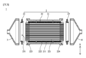
図1は、通常の燃料電池用加湿器の概略分解斜視図である。 Figure 1 is a schematic exploded perspective view of a typical fuel cell humidifier.

図1に例示するように、通常の膜加湿方式の加湿器100は、外部から供給される空気と燃料電池スタック(図示せず)から排出される排ガスとの間に水分取替が起きる加湿モジュール110、及び該加湿モジュール110の両端に結合しているギャップ120を含む。 As shown in FIG. 1, a typical membrane humidifier 100 includes a humidification module 110 in which moisture exchange occurs between air supplied from the outside and exhaust gas discharged from a fuel cell stack (not shown), and gaps 120 connected to both ends of the humidification module 110.

これらのギャップ120のいずれか一方は、外部から供給される空気を前記加湿モジュール110に伝達し、他方は、前記加湿モジュール110によって加湿された空気を燃料電池スタックに伝達する。 One of these gaps 120 transfers air supplied from the outside to the humidification module 110, and the other transfers air humidified by the humidification module 110 to the fuel cell stack.

前記加湿モジュール110は、排ガス湿潤気体流入口(off-gas inlet)111aと排ガス湿潤気体流出口(off-gas outlet)111bを有するミッドケース(mid-case)111、及び該ミッドケース111内の複数の中空糸膜112を含む。これらの中空糸膜112の束の両端は、硬質ポット部113にポットされている。前記硬質ポット部113は、一般に、キャスティング(casting)方式で液状ポリウレタン樹脂のような液状ポリマーを硬化させることによって形成される。 The humidification module 110 includes a mid-case 111 having an off-gas inlet 111a and an off-gas outlet 111b, and a plurality of hollow fiber membranes 112 in the mid-case 111. Both ends of the bundle of hollow fiber membranes 112 are potted in a hard pot portion 113. The hard pot portion 113 is generally formed by hardening a liquid polymer such as liquid polyurethane resin by a casting method.

外部から供給される空気は、前記中空糸膜112の中空に沿って流れる。前記排ガス湿潤気体流入口111aから前記ミッドケース111内に流入した排ガスは、前記中空糸膜112の外表面と接触した後、前記排ガス湿潤気体流出口111bを通って前記ミッドケース111から流出する。前記排ガスが前記中空糸膜112の外表面と接触する際に、前記排ガス中に含有されている水分が前記中空糸膜112を透過することにより、前記中空糸膜112の中空に沿って流れている空気を加湿する。 Air supplied from the outside flows along the hollow of the hollow fiber membrane 112. The exhaust gas that flows into the midcase 111 from the exhaust gas wet gas inlet 111a comes into contact with the outer surface of the hollow fiber membrane 112 and then flows out of the midcase 111 through the exhaust gas wet gas outlet 111b. When the exhaust gas comes into contact with the outer surface of the hollow fiber membrane 112, the moisture contained in the exhaust gas permeates the hollow fiber membrane 112, humidifying the air flowing along the hollow of the hollow fiber membrane 112.

一般に、図1に例示するように、前記中空糸膜112の末端がポットされている硬質ポット部113、及び硬質ポット部113と前記ミッドケース111との間の樹脂層114が、前記ギャップ120の内部空間を前記ミッドケース111の内部空間から遮断する。前記硬質ポット部113と類似に、前記樹脂層114も、一般に、キャスティング方式で液状ポリウレタン樹脂のような液状ポリマーを硬化させることによって形成される。 Generally, as shown in FIG. 1, a hard pot portion 113 to which the end of the hollow fiber membrane 112 is potted, and a resin layer 114 between the hard pot portion 113 and the midcase 111, isolate the internal space of the gap 120 from the internal space of the midcase 111. Similar to the hard pot portion 113, the resin layer 114 is also generally formed by hardening a liquid polymer such as liquid polyurethane resin by a casting method.

しかしながら、前記樹脂層114の形成のためのキャスティング工程は、相対的に長い工程時間がかかるため、加湿器100の生産性を低下させる問題があった。 However, the casting process for forming the resin layer 114 takes a relatively long process time, which reduces the productivity of the humidifier 100.

本発明は、上述したような問題を解決するために案出されたもので、キャスティング工程を用いた樹脂層の形成によって加湿器の生産性が低下することを防止できる燃料電池用加湿器を提供するためのものである。 The present invention has been devised to solve the problems described above, and aims to provide a humidifier for fuel cells that can prevent a decrease in the productivity of the humidifier due to the formation of a resin layer using a casting process.

前記のような課題を解決するために、本発明は次のような構成を含むことができる。 In order to solve the above problems, the present invention can include the following configurations:

本発明は、燃料電池スタックから排出された湿潤気体を用いて、外部から供給された乾燥気体を加湿するための加湿モジュール、及び前記加湿モジュールの一端に結合した第1キャップを含むことができる。前記加湿モジュールは、両端が開放しているミッドケース(mid-case)、及び前記ミッドケース内に配置され、多数の中空糸膜を含む少なくとも一つのカートリッジ(Cartridge)を含むことができる。前記カートリッジは、両端が開放しており、前記中空糸膜を収容するインナーケース(Inner Case)、及び前記中空糸膜の一端をポッティングする第1ポット層を含むことができる。 The present invention may include a humidification module for humidifying dry gas supplied from the outside using wet gas discharged from a fuel cell stack, and a first cap coupled to one end of the humidification module. The humidification module may include a mid-case having both open ends, and at least one cartridge disposed within the mid-case and including a number of hollow fiber membranes. The cartridge may include an inner case having both open ends and housing the hollow fiber membranes, and a first potting layer for potting one end of the hollow fiber membranes.

本発明の第1実施例による燃料電池用加湿器は、前記加湿モジュールが、前記第1キャップが前記中空糸膜のみと流体連通するように機械的組立によって前記加湿モジュールの一端に気密に結合した(Airtightly coupled)第1パッキング部材、前記第1パッキング部材と前記第1ポット層との間を密閉させる第1シーリング部、及び前記第1シーリング部の遊動可能距離を制限するように前記第1パッキング部材に結合した第1遮断部、を含み、前記第1シーリング部は、前記第1パッキング部材を基準にして、前記第1パッキング部材と前記第1キャップとの間の第1外部空間及び前記第1外部空間の反対側に配置された内部空間のうちの少なくとも一方に配置されることができる。 In the fuel cell humidifier according to the first embodiment of the present invention, the humidification module includes a first packing member airtightly coupled to one end of the humidification module by mechanical assembly so that the first cap is in fluid communication only with the hollow fiber membrane, a first sealing part that seals between the first packing member and the first pot layer, and a first blocking part that is coupled to the first packing member so as to limit the movable distance of the first sealing part, and the first sealing part may be disposed in at least one of a first external space between the first packing member and the first cap and an internal space disposed on the opposite side of the first external space, based on the first packing member.

本発明の第2実施例による燃料電池用加湿器は、前記第1キャップが前記中空糸膜のみと流体連通するように機械的組立によって前記加湿モジュールの一端に気密に結合した(Airtightly coupled)第1パッキング部材、前記第1パッキング部材を基準にして、前記ミッドケース側に配置された内部空間で前記第1パッキング部材と前記カートリッジとの間を密閉させる第1シーラントを含むことができる。前記第1パッキング部材は、前記第1シーラントを収容するための第1内部溝、前記第1内部溝の一側に配置された第1遮断部材、及び前記第1内部溝の他側に配置された第1区画部材を含み、前記第1遮断部材は前記内部空間側に前記第1内部溝よりも長く突出し、前記第1シーラントは前記第1内部溝に位置して前記第1遮断部材と前記第1ポット層との間を密閉させることができる。 The fuel cell humidifier according to the second embodiment of the present invention may include a first packing member airtightly coupled to one end of the humidification module by mechanical assembly so that the first cap is fluidically connected only to the hollow fiber membrane, and a first sealant that seals between the first packing member and the cartridge in an internal space arranged on the midcase side based on the first packing member. The first packing member includes a first internal groove for accommodating the first sealant, a first blocking member arranged on one side of the first internal groove, and a first partition member arranged on the other side of the first internal groove, and the first blocking member protrudes longer than the first internal groove toward the internal space, and the first sealant is located in the first internal groove to seal between the first blocking member and the first pot layer.

本発明によれば、次のような効果を図ることができる。 The present invention can achieve the following effects:

本発明は、キャップの内部空間とミッドケースの内部空間を密閉させるためのキャスティング工程が省略可能なように具現される。したがって、本発明は、生産のための工程時間の短縮によって生産性を増大させることができる。 The present invention is embodied in such a way that the casting process for sealing the internal space of the cap and the internal space of the mid case can be omitted. Therefore, the present invention can increase productivity by shortening the process time for production.

本発明は、キャスティング工程を省略することにより、カートリッジの周辺に形成され得る隙間を密閉させることで、乾燥気体と湿潤気体とが直接的に混合されることを防止するための密閉力を強化することができる。したがって、本発明は乾燥気体を加湿する加湿工程の安全性を向上させることができる。 By eliminating the casting process, the present invention can strengthen the sealing force to prevent the dry gas and the wet gas from directly mixing by sealing any gaps that may form around the cartridge. Therefore, the present invention can improve the safety of the humidification process that humidifies the dry gas.

本発明は、シーラントに突出構造を具現することで、シーラントによる密閉面積をもっと確保することができる。よって、本発明は、シーラントによる密閉力をもっと強化することができる。 The present invention can secure a larger sealing area by implementing a protruding structure in the sealant. Therefore, the present invention can further strengthen the sealing force of the sealant.

通常の燃料電池用加湿器の概略分解斜視図である。FIG. 1 is a schematic exploded perspective view of a typical fuel cell humidifier.

本発明に係る燃料電池用加湿器の概略分解斜視図である。1 is a schematic exploded perspective view of a humidifier for a fuel cell according to the present invention;

本発明に係る燃料電池用加湿器を図2のI-I線を基準にして示す概略分解断面図である。3 is a schematic exploded cross-sectional view of the fuel cell humidifier according to the present invention taken along line II in FIG. 2. FIG.

本発明に係る燃料電池用加湿器を図2のI-I線を基準にして示す概略結合断面図である。3 is a schematic cross-sectional view of a humidifier for a fuel cell according to the present invention taken along line II of FIG. 2;

図4のA部を拡大して示す概略断面図である。FIG. 5 is a schematic cross-sectional view showing an enlarged view of part A in FIG. 4 . 図4のA部を拡大して示す概略断面図である。FIG. 5 is a schematic cross-sectional view showing an enlarged view of part A in FIG. 4 . 図4のA部を拡大して示す概略断面図である。FIG. 5 is a schematic cross-sectional view showing an enlarged view of part A in FIG. 4 .

図2のI-I線を基準に示す部分側断面図である。3 is a partial cross-sectional side view taken along line II of FIG. 2.

本発明の補強材を説明するために図4のA部を拡大して示す概略断面図である。FIG. 5 is a schematic cross-sectional view showing an enlarged view of part A in FIG. 4 for explaining the reinforcing material of the present invention.

本発明に係る燃料電池用加湿器においてミッドケースに2個のカートリッジが結合する実施例を示す概略分解斜視図である。1 is a schematic exploded perspective view showing an embodiment in which two cartridges are coupled to a mid case in a humidifier for a fuel cell according to the present invention; FIG.

本発明に係る燃料電池用加湿器においてミッドケースに3個のカートリッジが結合する実施例を示す概略分解斜視図である。1 is a schematic exploded perspective view showing an embodiment in which three cartridges are coupled to a mid case in a humidifier for a fuel cell according to the present invention; FIG.

本発明に係る燃料電池用加湿器を図2のI-I線を基準に示す概略分解断面図である。3 is a schematic exploded cross-sectional view of the humidifier for a fuel cell according to the present invention taken along line II in FIG. 2.

本発明に係る燃料電池用加湿器を図2のI-I線を基準に示す概略結合断面図である。3 is a schematic cross-sectional view of a humidifier for a fuel cell according to the present invention taken along line II of FIG. 2;

図11のB部を拡大して示す概略断面図である。12 is a schematic cross-sectional view showing an enlarged view of part B in FIG. 11 .

図2のI-I線を基準に、第1パッキング部材、カートリッジ、及び第1シーラントが結合する前の形態を示す部分分解断面図である。3 is a partially exploded cross-sectional view taken along line II of FIG. 2, showing a state before the first packing member, the cartridge, and the first sealant are coupled together.

本発明に係る燃料電池用加湿器において第1パッキング部材がミッドケースに結合する前の形態を示す概略断面図である。4 is a schematic cross-sectional view showing a state before a first packing member is coupled to a mid case in the humidifier for a fuel cell according to the present invention; FIG.

第1パッキング部材がカートリッジに結合した形態を示す概略断面図である。FIG. 4 is a schematic cross-sectional view showing a state in which the first packing member is coupled to the cartridge. 第1パッキング部材がカートリッジに結合した形態を示す概略断面図である。FIG. 4 is a schematic cross-sectional view showing a state in which the first packing member is coupled to the cartridge.

本発明に係る燃料電池用加湿器においてミッドケースに2個のカートリッジが結合する実施例を示す概略分解斜視図である。1 is a schematic exploded perspective view showing an embodiment in which two cartridges are coupled to a mid case in a humidifier for a fuel cell according to the present invention; FIG.

本発明に係る燃料電池用加湿器においてミッドケースに3個のカートリッジが結合する実施例を示す概略分解斜視図である。1 is a schematic exploded perspective view showing an embodiment in which three cartridges are coupled to a mid case in a humidifier for a fuel cell according to the present invention; FIG.

以下では、本発明に係る燃料電池用加湿器の実施例を、添付の図面を参照して詳細に説明する。 Below, an embodiment of a humidifier for a fuel cell according to the present invention will be described in detail with reference to the attached drawings.

図2~図4、図10及び図11を参照すると、本発明に係る燃料電池用加湿器1は、燃料電池スタック(図示せず)から排出された湿潤気体を用いて、外部から供給された乾燥気体を加湿するためのものである。乾燥気体は、燃料ガス又は空気であってもよい。乾燥気体は湿潤気体によって加湿された後、前記燃料電池スタックに供給されることができる。本発明に係る燃料電池用加湿器1は、乾燥気体の加湿のための加湿モジュール2、及び前記加湿モジュール2の一端に結合している第1キャップ3を含む。前記加湿モジュール2は、複数の中空糸膜221が結合しているカートリッジ(Cartridge)22、前記カートリッジ22が結合しているミッドケース(Mid-case)21、及び前記カートリッジ22と前記ミッドケース21との間に配置され、前記カートリッジ22と前記ミッドケース21間を密閉させる第1パッキング部材23を含む。前記第1パッキング部材23は、キャスティング(casting)工程無しで、結合によって前記カートリッジ22と前記ミッドケース21間を密閉させることができる。これにより、前記第1パッキング部材23は、前記第1キャップ3の内部空間ISと前記ミッドケース21の内部空間ISを密閉させることができる。したがって、本発明に係る燃料電池用加湿器1は、相対的に長い工程時間がかかるキャスティング工程が省略できるので、生産のための工程時間の短縮によって生産性を増大させることができる。 2 to 4, 10 and 11, the humidifier 1 for a fuel cell according to the present invention is for humidifying dry gas supplied from the outside using wet gas discharged from a fuel cell stack (not shown). The dry gas may be a fuel gas or air. The dry gas may be humidified by the wet gas and then supplied to the fuel cell stack. The humidifier 1 for a fuel cell according to the present invention includes a humidification module 2 for humidifying dry gas, and a first cap 3 coupled to one end of the humidification module 2. The humidification module 2 includes a cartridge 22 to which a plurality of hollow fiber membranes 221 are coupled, a mid-case 21 to which the cartridge 22 is coupled, and a first packing member 23 disposed between the cartridge 22 and the mid-case 21 and sealing the space between the cartridge 22 and the mid-case 21. The first packing member 23 can seal the gap between the cartridge 22 and the mid case 21 by joining without a casting process. As a result, the first packing member 23 can seal the internal space IS of the first cap 3 and the internal space IS of the mid case 21. Therefore, the humidifier 1 for fuel cells according to the present invention can omit the casting process, which takes a relatively long process time, and can increase productivity by shortening the process time for production.

以下では、前記加湿モジュール2及び前記第1キャップ3について、添付の図面を参照して具体的に説明する。 The humidification module 2 and the first cap 3 are described in detail below with reference to the attached drawings.

図2~図4、図10及び図11を参照すると、前記加湿モジュール2は、外部から供給された気体を加湿するものである。前記加湿モジュール2は燃料電池スタックから排出された湿潤気体を用いて、外部から供給された乾燥気体を加湿することができる。前記加湿モジュール2の一端には前記第1キャップ3が結合することができる。前記加湿モジュール2の他端には第2キャップ4が結合することができる。前記第1キャップ3は、乾燥気体を前記加湿モジュール2に伝達することができる。この場合、前記第2キャップ4は、前記加湿モジュール2で湿潤気体によって加湿された乾燥気体を、前記燃料電池スタックに伝達することができる。前記第1キャップ3は湿潤気体を前記加湿モジュール2に伝達することができる。この場合、前記第2キャップ4は前記加湿モジュール2で乾燥気体を加湿した後の湿潤気体を外部に排出することができる。 Referring to FIG. 2 to FIG. 4, FIG. 10 and FIG. 11, the humidification module 2 humidifies gas supplied from the outside. The humidification module 2 can humidify dry gas supplied from the outside using wet gas discharged from the fuel cell stack. The first cap 3 can be coupled to one end of the humidification module 2. The second cap 4 can be coupled to the other end of the humidification module 2. The first cap 3 can deliver dry gas to the humidification module 2. In this case, the second cap 4 can deliver the dry gas humidified by the wet gas in the humidification module 2 to the fuel cell stack. The first cap 3 can deliver the wet gas to the humidification module 2. In this case, the second cap 4 can discharge the wet gas after the dry gas is humidified in the humidification module 2 to the outside.

前記加湿モジュール2は、前記カートリッジ22、前記ミッドケース21、及び前記第1パッキング部材23を含むことができる。 The humidification module 2 may include the cartridge 22, the midcase 21, and the first packing member 23.

前記カートリッジ22は、前記中空糸膜221を複数個含む。前記中空糸膜221は、前記カートリッジ22として具現され、モジュール化することができる。これにより、前記カートリッジ22を前記ミッドケース21に結合させる工程により、前記中空糸膜221は前記ミッドケース21の内部に設けられることができる。したがって、本発明に係る燃料電池用加湿器1は、前記中空糸膜221に対する設置作業、分離作業、及び取替作業の容易性を向上させることができる。前記カートリッジ22は、前記中空糸膜221を収容するインナーケース(Inner case)222を含むことができる。前記中空糸膜221は、前記インナーケース222の内部に配置されてモジュール化することができる。前記中空糸膜221は、ポリスルホン樹脂、ポリエーテルスルホン樹脂、スルホン化ポリスルホン樹脂、ポリビニリデンフルオリド(PVDF)樹脂、ポリアクリロニトリル(PAN)樹脂、ポリイミド樹脂、ポリアミドイミド樹脂、ポリエステルイミド樹脂、又はこれらのうち2以上の混合物で形成された高分子膜を含むことができる。 The cartridge 22 includes a plurality of the hollow fiber membranes 221. The hollow fiber membranes 221 can be embodied as the cartridge 22 and modularized. Thus, the hollow fiber membranes 221 can be provided inside the midcase 21 by a process of combining the cartridge 22 with the midcase 21. Therefore, the humidifier 1 for a fuel cell according to the present invention can improve the ease of installation, separation, and replacement of the hollow fiber membranes 221. The cartridge 22 can include an inner case 222 that houses the hollow fiber membranes 221. The hollow fiber membranes 221 can be modularized by being disposed inside the inner case 222. The hollow fiber membrane 221 can include a polymer membrane formed of polysulfone resin, polyethersulfone resin, sulfonated polysulfone resin, polyvinylidene fluoride (PVDF) resin, polyacrylonitrile (PAN) resin, polyimide resin, polyamide-imide resin, polyester-imide resin, or a mixture of two or more of these.

前記カートリッジ22は、第1ポット層223、及び第2ポット層224を含むことができる。前記第1ポット層223及び第2ポット層224は、前記多数の中空糸膜221の末端部がポッティングして、前記インナーケース222の開口を閉鎖させるものである。前記多数の中空糸膜221の一側が前記第1ポット層223によって固定され、前記多数の中空糸膜221の他側が前記第2ポット層224によって固定されることができる。前記第1ポット層223及び第2ポット層224は、キャスティング工程で液状ポリウレタン樹脂のような液状樹脂を硬化させることによって形成されることができる。前記第1ポット層223及び第2ポット層224は前記多数の中空糸膜221の末端部と前記インナーケース222とを固定させることもできる。 The cartridge 22 may include a first pot layer 223 and a second pot layer 224. The first pot layer 223 and the second pot layer 224 are potted with the ends of the hollow fiber membranes 221 to close the opening of the inner case 222. One side of the hollow fiber membranes 221 may be fixed by the first pot layer 223, and the other side of the hollow fiber membranes 221 may be fixed by the second pot layer 224. The first pot layer 223 and the second pot layer 224 may be formed by hardening a liquid resin such as a liquid polyurethane resin in a casting process. The first pot layer 223 and the second pot layer 224 may also fix the ends of the hollow fiber membranes 221 to the inner case 222.

前記第1ポット層223及び第2ポット層224は前記多数の中空糸膜221の中空を塞げないように形成されることができる。これにより、外部から供給された乾燥気体または湿潤気体は前記第1ポット層223及び第2ポット層224との干渉なしに前記中空糸膜221の中空に供給されることができ、前記第1ポット層223及び第2ポット層224との干渉なしに前記中空糸膜221の中空から流出することができる。 The first pot layer 223 and the second pot layer 224 can be formed so as not to block the hollows of the hollow fiber membranes 221. As a result, dry gas or wet gas supplied from the outside can be supplied to the hollows of the hollow fiber membranes 221 without interfering with the first pot layer 223 and the second pot layer 224, and can flow out of the hollows of the hollow fiber membranes 221 without interfering with the first pot layer 223 and the second pot layer 224.

前記カートリッジ22は、前記インナーケース222に形成された流入孔(図示せず)及び流出孔(図示せず)を含むことができる。前記流入孔は湿潤気体または乾燥気体を前記インナーケース222の内部に流入させるためのものである。前記流入孔は前記インナーケース222を貫通して形成されることができる。前記流出孔は湿潤気体または乾燥気体を前記インナーケース222の内部から外部に流出させることができる。 The cartridge 22 may include an inlet hole (not shown) and an outlet hole (not shown) formed in the inner case 222. The inlet hole is for allowing wet gas or dry gas to flow into the inside of the inner case 222. The inlet hole may be formed penetrating the inner case 222. The outlet hole may allow wet gas or dry gas to flow from the inside of the inner case 222 to the outside.

前記ミッドケース21は前記カートリッジ22が結合したものである。前記ミッドケース21は、内部に前記カートリッジ22を収容するための収容孔211を含むことができる。前記収容孔211は前記ミッドケース21の内部に配置されることができる。前記ミッドケース21の内面と前記カートリッジ22の外面との間に空間が形成されるように、前記カートリッジ22は前記収容孔211に挿入されることにより前記ミッドケース21の内部に配置されることができる。 The mid case 21 is connected to the cartridge 22. The mid case 21 may include an accommodating hole 211 for accommodating the cartridge 22 therein. The accommodating hole 211 may be disposed inside the mid case 21. The cartridge 22 may be disposed inside the mid case 21 by being inserted into the accommodating hole 211 so that a space is formed between the inner surface of the mid case 21 and the outer surface of the cartridge 22.

前記ミッドケース21の一側には流入口212及び流出口213が形成されることができる。 An inlet 212 and an outlet 213 may be formed on one side of the midcase 21.

前記流入口212は、前記ミッドケース21の内部に湿潤気体または乾燥気体を流入させることができる。前記流出口213は、前記ミッドケース21の内部から湿潤気体または乾燥気体を流出させることができる。前記流入口212、前記流出口213、及び前記ミッドケース21は一体に形成されることができる。 The inlet 212 can allow wet gas or dry gas to flow into the inside of the midcase 21. The outlet 213 can allow wet gas or dry gas to flow out from the inside of the midcase 21. The inlet 212, the outlet 213, and the midcase 21 can be integrally formed.

前記流入口212及び前記流出口213を通して湿潤気体が遊動する場合、湿潤気体は前記流入口212を通して前記ミッドケース21の内面と前記インナーケース222の外面との間に供給され、前記流入孔を通して前記インナーケース222の内部に供給されて前記中空糸膜221の外表面と接触することができる。この過程で、湿潤気体に含有されていた水分が前記中空糸膜221を透過することで、前記中空糸膜221の中空に沿って流れる乾燥気体を加湿することができる。加湿された乾燥気体は前記中空糸膜221から流出した後、前記第2キャップ4を通して前記燃料電池スタックに供給されることができる。乾燥気体を加湿した後の湿潤気体は前記流出孔を通して前記インナーケース222の外面と前記ミッドケース21の内面との間に流出し、前記流出口213を通して前記ミッドケース21の外部に流出することができる。前記流入口212は前記燃料電池スタックに連結されて湿潤気体を受けることができる。この場合、湿潤気体は前記燃料電池スタックから排出される排ガス(Off-gas)であり得る。 When the wet gas moves through the inlet 212 and the outlet 213, the wet gas can be supplied between the inner surface of the midcase 21 and the outer surface of the inner case 222 through the inlet 212, and can be supplied to the inside of the inner case 222 through the inlet hole and contact the outer surface of the hollow fiber membrane 221. In this process, moisture contained in the wet gas can permeate the hollow fiber membrane 221 to humidify the dry gas flowing along the hollow of the hollow fiber membrane 221. The humidified dry gas can be supplied to the fuel cell stack through the second cap 4 after flowing out of the hollow fiber membrane 221. The wet gas after humidifying the dry gas can flow out between the outer surface of the inner case 222 and the inner surface of the midcase 21 through the outlet hole and can flow out to the outside of the midcase 21 through the outlet 213. The inlet 212 can be connected to the fuel cell stack to receive the wet gas. In this case, the wet gas may be off-gas discharged from the fuel cell stack.

前記流入口212及び前記流出口213を通して乾燥気体が遊動する場合、乾燥気体は前記流入口212を通して前記ミッドケース21の内面と前記インナーケース222の外面との間に供給され、前記流入孔を通して前記インナーケース222の内部に供給されて前記中空糸膜221の外表面と接触することができる。この過程で、湿潤気体に含有されていた水分が前記中空糸膜221を透過することで、前記インナーケース222の内部に流入された乾燥気体を加湿することができる。加湿された乾燥気体は、前記流出孔を通して前記インナーケース222の外面と前記ミッドケース21の内面との間に流出し、前記流出口213を通して前記ミッドケース21の外部に流出した後、前記燃料電池スタックに供給されることができる。乾燥気体を加湿した後の湿潤気体は前記中空糸膜221から流出した後、前記第2キャップ4を通して外部に排出されることができる。前記第1キャップ3は前記燃料電池スタックに連結され、湿潤気体を受けることができる。この場合、湿潤気体は前記燃料電池スタックから排出される排ガス(Off-gas)であり得る。 When the dry gas floats through the inlet 212 and the outlet 213, the dry gas can be supplied between the inner surface of the midcase 21 and the outer surface of the inner case 222 through the inlet 212, and can be supplied to the inside of the inner case 222 through the inlet hole to come into contact with the outer surface of the hollow fiber membrane 221. In this process, moisture contained in the wet gas can permeate the hollow fiber membrane 221 to humidify the dry gas flowing into the inside of the inner case 222. The humidified dry gas can flow between the outer surface of the inner case 222 and the inner surface of the midcase 21 through the outlet hole, and can flow out to the outside of the midcase 21 through the outlet 213 and then be supplied to the fuel cell stack. The wet gas after humidifying the dry gas can flow out of the hollow fiber membrane 221 and then be discharged to the outside through the second cap 4. The first cap 3 is connected to the fuel cell stack and can receive the wet gas. In this case, the wet gas may be off-gas discharged from the fuel cell stack.

図2~図20を参照すると、前記第1パッキング部材23は前記カートリッジ22と前記ミッドケース21との間を密閉させるものである。前記第1パッキング部材23は乾燥気体と湿潤気体が直接的に混合されることを防止することができる。前記第1パッキング部材23は前記カートリッジ22と前記ミッドケース21との間に配置されることができる。この場合、前記カートリッジ22は前記第1パッキング部材23に形成された第1通過孔231に挿入されることができる。前記第1パッキング部材23は前記カートリッジ22と密着することで、前記カートリッジ22と前記ミッドケース21との間を密閉することができる。この場合、前記カートリッジ22のサイズは前記第1通過孔231より大きく形成されることができる。これにより、前記カートリッジ22は前記第1通過孔231に締まりばめ方式で挿入されることができる。前記第1パッキング部材23は弾性変形(Elastic Deformation)可能な素材から形成されることができる。例えば、前記第1パッキング部材23はゴム類から形成されることができる。前記第1パッキング部材23は、前記カートリッジ22と前記ミッドケース21との間を密閉するように、枠形に形成されることができるが、必ずしもこれに限定されず、前記第1パッキング部材23が前記カートリッジ22と前記ミッドケース21との間を密閉することができれば、他の形態にも形成されることができる。 2 to 20, the first packing member 23 seals the gap between the cartridge 22 and the mid case 21. The first packing member 23 can prevent the dry gas and the wet gas from being directly mixed. The first packing member 23 can be disposed between the cartridge 22 and the mid case 21. In this case, the cartridge 22 can be inserted into a first passage hole 231 formed in the first packing member 23. The first packing member 23 can seal the gap between the cartridge 22 and the mid case 21 by being in close contact with the cartridge 22. In this case, the size of the cartridge 22 can be formed larger than the first passage hole 231. Thus, the cartridge 22 can be inserted into the first passage hole 231 in a press-fit manner. The first packing member 23 can be made of a material capable of elastic deformation. For example, the first packing member 23 can be made of rubber. The first packing member 23 may be formed in a frame shape to seal the gap between the cartridge 22 and the mid case 21, but is not limited thereto, and may be formed in other shapes as long as the first packing member 23 can seal the gap between the cartridge 22 and the mid case 21.

ここで、本発明に係る燃料電池用加湿器1は、前記カートリッジ22と前記ミッドケース21との間を密閉する構造に対するさまざまな実施例を含むことができる。以下では、前記カートリッジ22と前記ミッドケース21との間を密閉する構造の実施例について添付図面を参照して詳細に説明する。 Here, the humidifier 1 for fuel cells according to the present invention may include various embodiments of the structure for sealing the gap between the cartridge 22 and the mid-case 21. Hereinafter, embodiments of the structure for sealing the gap between the cartridge 22 and the mid-case 21 will be described in detail with reference to the accompanying drawings.

<第1実施例による燃料電池用加湿器> <First embodiment of a humidifier for fuel cells>

図2~図11を参照すると、第1実施例による燃料電池用加湿器1は、第1シーリング部240、及び第1遮断部260を含むことができる。 Referring to Figures 2 to 11, the humidifier 1 for a fuel cell according to the first embodiment may include a first sealing portion 240 and a first blocking portion 260.

前記第1シーリング部240は前記第1パッキング部材23と前記第1ポット層223との間を密閉させるものである。前記シーリング部240は、前記第1パッキング部材23を基準にして、前記第1パッキング部材23と前記第1キャップ3との間の第1外部空間OS及び前記第1外部空間OSの反対側に配置された内部空間ISのうちの少なくとも一方に配置されることができる。 The first sealing part 240 seals the gap between the first packing member 23 and the first pot layer 223. The sealing part 240 may be disposed in at least one of a first external space OS between the first packing member 23 and the first cap 3 and an internal space IS disposed on the opposite side of the first external space OS, based on the first packing member 23.

例えば、図5のように、前記第1シーリング部240は前記第1外部空間OSに配置され、前記第1パッキング部材23と前記第1ポット層223との間を密閉させることができる。例えば、図6のように、前記第1シーリング部240は前記内部空間ISに配置され、前記第1パッキング部材23と前記第1ポット層223との間を密閉させることができる。前記第1シーリング部240は前記外部空間OS及び前記内部空間ISの両方に配置されることで、前記第1パッキング部材23と前記第1ポット層223との間を前記外部空間OS及び前記内部空間ISでそれぞれ密閉させることもできる。 5, the first sealing part 240 is disposed in the first external space OS, and can seal the gap between the first packing member 23 and the first pot layer 223. For example, as shown in FIG. 6, the first sealing part 240 is disposed in the internal space IS, and can seal the gap between the first packing member 23 and the first pot layer 223. The first sealing part 240 can be disposed in both the external space OS and the internal space IS, and can seal the gap between the first packing member 23 and the first pot layer 223 in the external space OS and the internal space IS, respectively.

したがって、第1実施例による燃料電池用加湿器1は、前記第1パッキング部材23と前記第1ポット層223との組立構造によって前記第1キャップ3が前記中空糸膜221のみと流体連通するように前記第1キャップ3と前記第1ポット層223との間を密閉させる構造の製造容易性を向上させることに加えて、前記第1シーリング部240によって前記第1パッキング部材23と前記第1ポット層223との間に形成される隙間を通して流体が移動することを防止することで、前記第1キャップ3と前記第1ポット層223との間を密閉させる構造の気密性を向上させることができる。前記シーリング部240は、液状ポリウレタン樹脂、液状シリコン樹脂、液状エポキシ樹脂、液状エラストマー樹脂、及びその組合せからなる群から選択された液状樹脂であり、前記第1パッキング部材23に塗布された後、前記第1パッキング部材23が前記カートリッジ22と前記ミッドケース21との間に配置されると、硬化して第1ポット層223と前記第1パッキング部材23との間を密閉することができる。前記シーリング部240は、前記第1パッキング部材23が前記カートリッジ22と前記ミッドケース21との間に配置された後、前記第1ポット層223と前記第1パッキング部材23との間の隙間を詰めるように塗布されて硬化することで、前記カートリッジ22と前記ミッドケース21との間を密閉することもできる。 Therefore, in the fuel cell humidifier 1 according to the first embodiment, in addition to improving the ease of manufacture of the structure sealing between the first cap 3 and the first pot layer 223 so that the first cap 3 is fluidically connected only to the hollow fiber membrane 221 due to the assembly structure of the first packing member 23 and the first pot layer 223, the first sealing part 240 prevents fluid from moving through the gap formed between the first packing member 23 and the first pot layer 223, thereby improving the airtightness of the structure sealing between the first cap 3 and the first pot layer 223. The sealing part 240 is a liquid resin selected from the group consisting of liquid polyurethane resin, liquid silicone resin, liquid epoxy resin, liquid elastomer resin, and combinations thereof, and after being applied to the first packing member 23, when the first packing member 23 is disposed between the cartridge 22 and the mid case 21, it can be hardened to seal between the first pot layer 223 and the first packing member 23. After the first packing member 23 is disposed between the cartridge 22 and the midcase 21, the sealing portion 240 is applied to fill the gap between the first pot layer 223 and the first packing member 23 and hardened, thereby sealing the gap between the cartridge 22 and the midcase 21.

図5及び図7を参照すると、前記第1シーリング部240が前記第1外部空間OSに配置されるように具現される場合、前記第1シーリング部240は前記第1外部シーラント24を含むことができる。 Referring to FIG. 5 and FIG. 7, when the first sealing part 240 is embodied to be disposed in the first external space OS, the first sealing part 240 may include the first external sealant 24.

前記第1外部シーラント24は前記第1外部空間OSで前記第1ポット層223と前記第1パッキング部材23との間を密閉させるものである。前記第1外部シーラント24は前記外部空間OSで前記第1パッキング部材23と前記第1ポット層223との間を密閉させることができる。前記第1外部シーラント24は、前記第1パッキング部材23を基準に、前記第1外部空間OSに向かうように配置されることができる。前記第1外部シーラント24は、前記カートリッジ22が前記第1通過孔231に挿入されるのに伴い、前記第1ポット層223と前記第1パッキング部材23との間に形成される隙間に塗布された後、硬化することができる。よって、前記第1外部シーラント24は前記第1外部空間OSで前記第1パッキング部材23と前記第1ポット層223との間に形成された隙間を密閉することで、前記第1パッキング部材23と前記第1ポット層223との間で乾燥気体と湿潤気体とが直接的に混合されることを防止することができる。前記第1外部シーラント24は、液状ポリウレタン樹脂、液状シリコン樹脂、液状エポキシ樹脂、液状エラストマー樹脂、及びその組合せからなる群から選択された液状樹脂であり、前記第1パッキング部材23に塗布された後、前記第1パッキング部材23が前記カートリッジ22と前記ミッドケース21との間に配置されると、硬化して前記第1外部空間OSで第1ポット層223と前記第1パッキング部材23との間を密閉することができる。前記第1外部シーラント24は、前記第1パッキング部材23が前記カートリッジ22と前記ミッドケース21との間に配置された後、前記第1ポット層223と前記第1パッキング部材23との間の隙間を詰めるように塗布されて硬化することで、前記カートリッジ22と前記ミッドケース21との間を密閉することもできる。 The first external sealant 24 seals the gap between the first pot layer 223 and the first packing member 23 in the first external space OS. The first external sealant 24 can seal the gap between the first packing member 23 and the first pot layer 223 in the external space OS. The first external sealant 24 can be arranged to face the first external space OS based on the first packing member 23. The first external sealant 24 can be applied to the gap formed between the first pot layer 223 and the first packing member 23 as the cartridge 22 is inserted into the first through hole 231, and then hardened. Therefore, the first external sealant 24 seals the gap formed between the first packing member 23 and the first pot layer 223 in the first external space OS, thereby preventing the dry gas and the wet gas from being directly mixed between the first packing member 23 and the first pot layer 223. The first external sealant 24 is a liquid resin selected from the group consisting of liquid polyurethane resin, liquid silicone resin, liquid epoxy resin, liquid elastomer resin, and combinations thereof. After being applied to the first packing member 23, the first packing member 23 is placed between the cartridge 22 and the mid case 21, and then hardened to seal the gap between the first pot layer 223 and the first packing member 23 in the first external space OS. The first external sealant 24 can also be applied to fill the gap between the first pot layer 223 and the first packing member 23 after the first packing member 23 is placed between the cartridge 22 and the mid case 21, and then hardened to seal the gap between the cartridge 22 and the mid case 21.

図6及び図7を参照すると、前記第1シーリング部240が前記内部空間ISに配置されるように具現される場合、前記第1シーリング部240は前記第1内部シーラント25を含むことができる。 Referring to FIG. 6 and FIG. 7, when the first sealing portion 240 is embodied to be disposed in the internal space IS, the first sealing portion 240 may include the first internal sealant 25.

前記第1内部シーラント25は前記内部空間ISで前記第1ポット層223と前記第1パッキング部材23との間を密閉させるものである。前記第1内部シーラント25は、前記第1パッキング部材23を基準にして、前記第1外部空間OSの反対側に配置された内部空間ISで前記第1パッキング部材23と前記第1ポット層223との間を密閉させるものである。前記第1内部シーラント25は、前記第1パッキング部材23を基準に、前記ミッドケース21の内部に向かうように配置されることができる。前記第1内部シーラント25は、前記カートリッジ22が前記第1通過孔231に挿入されるのに伴い、前記第1ポット層223と前記第1パッキング部材23との間に形成される隙間に塗布された後、硬化することができる。よって、前記第1内部シーラント25は前記内部空間ISで前記第1パッキング部材23と前記第1ポット層223との間に形成された隙間を密閉することで、前記第1パッキング部材23と前記第1ポット層223との間で乾燥気体と湿潤気体とが直接的に混合されることを防止することができる。前記第1内部シーラント25は、液状ポリウレタン樹脂、液状シリコン樹脂、液状エポキシ樹脂、液状エラストマー樹脂、及びその組合せからなる群から選択された液状樹脂であり、前記第1パッキング部材23に塗布された後、前記第1パッキング部材23が前記カートリッジ22と前記ミッドケース21との間に配置されると、硬化して前記内部空間ISで前記カートリッジ22と前記第1パッキング部材23との間を密閉することができる。前記第1内部シーラント25は、前記第1パッキング部材23が前記カートリッジ22と前記ミッドケース21との間に配置された後、前記カートリッジ22と前記ミッドケース21との間の隙間を詰めるように塗布されて硬化することで、前記カートリッジ22と前記ミッドケース21との間を密閉することもできる。 The first internal sealant 25 seals the gap between the first pot layer 223 and the first packing member 23 in the internal space IS. The first internal sealant 25 seals the gap between the first packing member 23 and the first pot layer 223 in the internal space IS arranged on the opposite side of the first external space OS with respect to the first packing member 23. The first internal sealant 25 may be arranged to face the inside of the mid case 21 with respect to the first packing member 23. The first internal sealant 25 may be applied to a gap formed between the first pot layer 223 and the first packing member 23 as the cartridge 22 is inserted into the first through hole 231, and then hardened. Therefore, the first internal sealant 25 seals the gap formed between the first packing member 23 and the first pot layer 223 in the internal space IS, thereby preventing direct mixing of dry gas and wet gas between the first packing member 23 and the first pot layer 223. The first internal sealant 25 is a liquid resin selected from the group consisting of liquid polyurethane resin, liquid silicone resin, liquid epoxy resin, liquid elastomer resin, and combinations thereof, and is applied to the first packing member 23 and then hardened when the first packing member 23 is disposed between the cartridge 22 and the mid case 21 to seal the gap between the cartridge 22 and the first packing member 23 in the internal space IS. The first internal sealant 25 can also be applied to fill the gap between the cartridge 22 and the mid case 21 after the first packing member 23 is disposed between the cartridge 22 and the mid case 21, and hardened to seal the gap between the cartridge 22 and the mid case 21.

図5~図7を参照すると、前記第1シーリング部240が前記第1外部空間OS及び前記内部空間ISの両方に配置されるように具現される場合、前記第1シーリング部240は前記第1外部シーラント24及び前記第1内部シーラント25の両者を含むこともできる。したがって、第1実施例による燃料電池用加湿器1は次のような作用効果を図ることができる。 Referring to Figures 5 to 7, when the first sealing part 240 is embodied to be disposed in both the first external space OS and the internal space IS, the first sealing part 240 may include both the first external sealant 24 and the first internal sealant 25. Therefore, the humidifier 1 for a fuel cell according to the first embodiment can achieve the following effects.

第一、第1実施例による燃料電池用加湿器1は、第1パッキング部材23を用いて前記カートリッジ22と前記ミッドケース21との間を密閉させることに加えて、シーラントを用いて前記第1パッキング部材23と前記第1ポット層223との間を密閉させることで、前記第1パッキング部材23と前記カートリッジ22との間の密閉力を強化することができる。 The fuel cell humidifier 1 according to the first and first embodiments uses a first packing member 23 to seal between the cartridge 22 and the midcase 21, and also uses a sealant to seal between the first packing member 23 and the first pot layer 223, thereby strengthening the sealing force between the first packing member 23 and the cartridge 22.

第二、前記第1外部シーラント24が前記第1外部空間OSで前記第1パッキング部材23と前記第1ポット層223との間を密閉することに加えて、前記第1内部シーラント25が前記内部空間ISで前記第1パッキング部材23と前記第1ポット層223との間を密閉するので、シーラントによる二重密閉構造を具現することができる。したがって、第1実施例による燃料電池用加湿器1は、シーラントによって前記第1パッキング部材23と前記第1ポット層223との間の密閉面積を増大させることができるので、前記第1パッキング部材23と前記カートリッジ22との間の密閉力をもっと強化することができる。 Second, the first external sealant 24 seals between the first packing member 23 and the first pot layer 223 in the first external space OS, and the first internal sealant 25 seals between the first packing member 23 and the first pot layer 223 in the internal space IS, so that a double sealed structure using a sealant can be realized. Therefore, in the fuel cell humidifier 1 according to the first embodiment, the sealing area between the first packing member 23 and the first pot layer 223 can be increased by the sealant, so that the sealing force between the first packing member 23 and the cartridge 22 can be further strengthened.

第三、前記第1外部シーラント24によって、前記第1外部空間OSから前記第1パッキング部材23と前記第1ポット層223との間に形成された空間に気体が流入することを防止するとともに、前記第1内部シーラント25によって、前記内部空間ISから前記第1パッキング部材23と前記第1ポット層223との間に形成された空間に気体が流入することを防止することができる。これにより、前記第1パッキング部材23と前記第1ポット層223との間に浸透した気体によって前記第1パッキング部材23が前記第1ポット層223から分離される方向に力を受けることを防止することができる。よって、第1実施例による燃料電池用加湿器1は、前記第1パッキング部材23と前記カートリッジ22との密着力が低下することを防止することができる。 Third, the first external sealant 24 prevents gas from flowing from the first external space OS into the space formed between the first packing member 23 and the first pot layer 223, and the first internal sealant 25 prevents gas from flowing from the internal space IS into the space formed between the first packing member 23 and the first pot layer 223. This prevents the first packing member 23 from receiving a force in a direction to separate from the first pot layer 223 due to the gas that has permeated between the first packing member 23 and the first pot layer 223. Therefore, the fuel cell humidifier 1 according to the first embodiment can prevent the adhesion between the first packing member 23 and the cartridge 22 from decreasing.

第四、前記第1外部シーラント24及び前記第1内部シーラント25は液状として塗布されることにより、前記第1パッキング部材23と前記第1ポット層223との間の隙間の形態やサイズにかかわらず、前記第1パッキング部材23と前記第1ポット層223との間を密閉させることができる。したがって、前記第1パッキング部材23及び前記カートリッジ22を密閉させるための作業において前記第1パッキング部材23及び前記カートリッジ22の形態に対する対応力を向上させることができる。 Fourth, since the first outer sealant 24 and the first inner sealant 25 are applied in a liquid form, the gap between the first packing member 23 and the first pot layer 223 can be sealed regardless of the shape or size of the gap between the first packing member 23 and the first pot layer 223. Therefore, the ability to adapt to the shape of the first packing member 23 and the cartridge 22 can be improved in the operation of sealing the first packing member 23 and the cartridge 22.

図2~図6を参照すると、前記加湿モジュール2は第1遮断部260を含むことができる。 Referring to Figures 2 to 6, the humidification module 2 may include a first blocking portion 260.

前記第1遮断部260は、前記第1シーリング部240の遊動可能距離を制限するように、前記第1パッキング部材23に結合したものである。前記第1遮断部260は、前記第1シーリング部240を基準に、前記第1ポット層223の反対側に位置するように、前記第1パッキング部材23に結合することができる。これにより、前記第1遮断部260は、前記第1シーリング部240が液状として塗布された後に硬化する過程で前記第1ポット層223によって押圧されるか、または前記第1シーリング部240の自重によって前記第1ポット層223から遠ざかる方向に遊動することを防止することで、前記第1シーリング部240による密閉力が低下することを防止することができる。 The first blocking part 260 is connected to the first packing member 23 so as to limit the movable distance of the first sealing part 240. The first blocking part 260 can be connected to the first packing member 23 so as to be located on the opposite side of the first pot layer 223 with respect to the first sealing part 240. As a result, the first blocking part 260 is pressed by the first pot layer 223 during the process in which the first sealing part 240 is applied in a liquid state and hardens, or the first sealing part 240 prevents the first blocking part 260 from moving in a direction away from the first pot layer 223 due to its own weight, thereby preventing a decrease in the sealing force of the first sealing part 240.

図7を参照すると、前記第1遮断部260は、第1外部遮断部26、及び第1内部遮断部27を含むことができる。 Referring to FIG. 7, the first blocking portion 260 may include a first outer blocking portion 26 and a first inner blocking portion 27.

前記第1外部遮断部26は前記第1外部シーラント24の遊動可能距離を制限するためのものである。前記第1外部遮断部26は前記第1パッキング部材23に結合することができる。前記第1内部遮断部27は前記第1内部シーラント25の遊動可能距離を制限するためのものである。前記第1内部遮断部27は前記第1パッキング部材23に結合することができる。前記第1内部遮断部27は前記第1外部遮断部26から離隔した位置で前記第1パッキング部材23に結合することができる。例えば、前記第1外部遮断部26は前記第1パッキング部材23において前記第1キャップ3に向かう側に配置された面に結合し、前記第1内部遮断部27は、前記第1パッキング部材23を基準に、前記内部空間ISに向かう側に配置された面に結合することができる。前記第1内部遮断部27は複数形成されることができる。この場合、前記第1内部遮断部27は前記第1軸方向(X軸方向)に沿って離隔して配置されることができる。 The first external blocking part 26 is for limiting the free movement distance of the first external sealant 24. The first external blocking part 26 may be coupled to the first packing member 23. The first internal blocking part 27 is for limiting the free movement distance of the first internal sealant 25. The first internal blocking part 27 may be coupled to the first packing member 23. The first internal blocking part 27 may be coupled to the first packing member 23 at a position separated from the first external blocking part 26. For example, the first external blocking part 26 may be coupled to a surface of the first packing member 23 that faces the first cap 3, and the first internal blocking part 27 may be coupled to a surface that faces the internal space IS with respect to the first packing member 23. The first internal blocking part 27 may be formed in plurality. In this case, the first internal blocking part 27 may be arranged at a distance along the first axis direction (X-axis direction).

前記第1パッキング部材23は、前記第1外部シーラント24を収容するための第1外部溝232、及び前記第1内部シーラント25を収容するための第1内部溝233を含むことができる。 The first packing member 23 may include a first outer groove 232 for accommodating the first outer sealant 24 and a first inner groove 233 for accommodating the first inner sealant 25.

前記第1外部溝232は前記第1外部遮断部26と前記第1ポット層223との間に配置されることができる。前記第1外部シーラント24は前記第1外部溝232に収容されるように塗布された後に硬化することができる。前記第1外部シーラント24は前記第1外部溝232に収容されることにより、前記第1外部遮断部26と前記第1ポット層223との間に位置することができる。このように、前記第1外部シーラント24は前記第1外部溝232に沿って塗布されて硬化することで、前記第1パッキング部材23と前記第1ポット層223との間を密閉させることができる。前記第1外部遮断部26は、前記第1外部溝232に収容された前記第1外部シーラント24の遊動可能距離を制限することができる。前記第1外部遮断部26は前記第1パッキング部材23から突出するように前記第1パッキング部材23に結合することができる。これにより、前記第1外部溝232に収容された前記第1外部シーラント24の遊動は前記第1外部遮断部26によって制限することができる。 The first external groove 232 may be disposed between the first external blocking part 26 and the first pot layer 223. The first external sealant 24 may be applied to be accommodated in the first external groove 232 and then cured. The first external sealant 24 may be positioned between the first external blocking part 26 and the first pot layer 223 by being accommodated in the first external groove 232. In this manner, the first external sealant 24 may be applied along the first external groove 232 and cured to seal the first packing member 23 and the first pot layer 223. The first external blocking part 26 may limit the free movement distance of the first external sealant 24 accommodated in the first external groove 232. The first external blocking part 26 may be coupled to the first packing member 23 so as to protrude from the first packing member 23. Thus, the free movement of the first external sealant 24 accommodated in the first external groove 232 may be limited by the first external blocking part 26.

前記第1内部溝233は前記第1内部遮断部27と前記第1ポット層223との間に配置されることができる。前記第1内部シーラント25は前記第1内部溝233に収容されるように塗布された後に硬化することができる。前記第1内部シーラント25は前記第1内部溝233に収容されることにより、前記第1内部遮断部27と前記第1ポット層223との間に位置することができる。これにより、前記第1内部遮断部27は前記第1内部溝233に収容されて硬化することで、前記第1パッキング部材23と前記第1ポット層223との間を密閉させることができる。前記第1内部遮断部27は前記第1内部溝233に収容された前記第1内部シーラント25の遊動可能距離を制限することができる。前記第1内部遮断部27は前記第1パッキング部材23から突出するように前記第1パッキング部材23に結合することができる。これにより、前記第1内部溝233に収容された前記第1内部シーラント25の遊動は前記第1内部遮断部27によって制限することができる。 The first internal groove 233 may be disposed between the first internal blocking part 27 and the first pot layer 223. The first internal sealant 25 may be applied to be accommodated in the first internal groove 233 and then cured. The first internal sealant 25 may be positioned between the first internal blocking part 27 and the first pot layer 223 by being accommodated in the first internal groove 233. Thus, the first internal blocking part 27 may be accommodated in the first internal groove 233 and cured to seal the first packing member 23 and the first pot layer 223. The first internal blocking part 27 may limit the free movement distance of the first internal sealant 25 accommodated in the first internal groove 233. The first internal blocking part 27 may be coupled to the first packing member 23 so as to protrude from the first packing member 23. Thus, the free movement of the first internal sealant 25 accommodated in the first internal groove 233 may be limited by the first internal blocking part 27.

したがって、第1実施例による燃料電池用加湿器1は次のような作用効果を図ることができる。 Therefore, the fuel cell humidifier 1 according to the first embodiment can achieve the following effects:

第一、第1外部溝232は前記第1外部シーラント24が塗布される経路をガイドし、前記第1内部溝233は前記第1内部シーラント25が塗布される経路をガイドすることで、前記第1外部シーラント24及び前記第1内部シーラント25の塗布作業の容易性及び正確性を向上させることができる。 The first and second outer grooves 232 guide the path along which the first outer sealant 24 is applied, and the first inner groove 233 guides the path along which the first inner sealant 25 is applied, thereby improving the ease and accuracy of the application of the first outer sealant 24 and the first inner sealant 25.

第二、前記第1外部溝232及び前記第1内部溝233はそれぞれ前記第1外部シーラント24及び前記第1内部シーラント25を収容することで、前記第1外部シーラント24及び前記第1内部シーラント25が硬化する前に塗布位置を脱して遊動することを制限することができる。これにより、第1外部シーラント24及び前記第1内部シーラント25が塗布位置を脱することによって前記第1パッキング部材23と前記第1ポット層223との間を密閉させるシーラントの比が低下する程度を減らすことができる。したがって、本発明に係る燃料電池用加湿器1は、シーラントによる密閉作業の正確性をもっと向上させ、シーラントによる密閉効率を増大させることで、シーラントによる密閉作業に投入されるコストを低めることができる。 Second, the first external groove 232 and the first internal groove 233 respectively accommodate the first external sealant 24 and the first internal sealant 25, thereby restricting the first external sealant 24 and the first internal sealant 25 from moving out of their application positions before hardening. This reduces the degree to which the ratio of the sealant that seals between the first packing member 23 and the first pot layer 223 decreases due to the first external sealant 24 and the first internal sealant 25 moving out of their application positions. Therefore, the humidifier 1 for fuel cells according to the present invention can further improve the accuracy of the sealing operation using the sealant and increase the sealing efficiency using the sealant, thereby reducing the cost of the sealing operation using the sealant.

前記第1外部溝232及び前記第1内部溝233は半球形に形成されることができるが、必ずしもこれに限定されず、前記第1外部シーラント24及び前記第1内部シーラント25を収容することができれば、他の形態に形成されることができる。前記第1外部溝232及び前記第1内部溝233は前記第1パッキング部材23と前記第1ポット層223とが交わる境界に沿って閉曲線形に形成されることができる。 The first external groove 232 and the first internal groove 233 may be formed in a hemispherical shape, but are not limited thereto, and may be formed in other shapes as long as they can accommodate the first external sealant 24 and the first internal sealant 25. The first external groove 232 and the first internal groove 233 may be formed in a closed curve shape along the boundary where the first packing member 23 and the first pot layer 223 intersect.

図2~図4及び図7を参照すると、前記第1外部遮断部26は前記第1外部溝232に収容された前記第1外部シーラント24の遊動可能距離を制限するためのものである。前記第1外部遮断部26は前記第1パッキング部材23から突出するように前記第1パッキング部材23に結合することができる。これにより、前記第1外部溝232に収容された前記第1外部シーラント24の遊動は前記第1外部遮断部26によって制限することができる。よって、第1実施例による燃料電池用加湿器1は、前記第1外部溝232に加えて、前記第1外部遮断部26を用いて前記第1外部シーラント24の遊動を制限することで、シーラント塗布作業の正確性をもっと向上させ、第1外部シーラント24によって密閉する作業の安全性をもっと向上させることができる。 Referring to FIG. 2 to FIG. 4 and FIG. 7, the first external blocking part 26 is for limiting the movable distance of the first external sealant 24 housed in the first external groove 232. The first external blocking part 26 may be coupled to the first packing member 23 so as to protrude from the first packing member 23. Thus, the movable distance of the first external sealant 24 housed in the first external groove 232 may be limited by the first external blocking part 26. Therefore, the fuel cell humidifier 1 according to the first embodiment may further improve the accuracy of the sealant application operation and further improve the safety of the sealing operation using the first external sealant 24 by limiting the movable distance of the first external sealant 24 using the first external blocking part 26 in addition to the first external groove 232.

前記第1外部遮断部26は、第1外部遮断部材261、及び第1外部区画部材262を含むことができる。 The first external shielding section 26 may include a first external shielding member 261 and a first external partition member 262.

前記第1外部遮断部材261は前記第1外部溝232に収容された前記第1外部シーラント24が遊動することを制限するためのものである。前記第1パッキング部材23から前記第1外部空間OSに向かって突設されることができる。前記第1外部遮断部材261は前記第1外部溝232を取り囲むように配置されることができる。この場合、前記第1外部シーラント24は前記第1外部遮断部材261と前記第1ポット層223との間に配置されることができる。これにより、前記第1外部溝232に収容された前記第1外部シーラント24が前記第1ポット層223に向かう方向の反対方向に遊動することを制限することができる。 The first external blocking member 261 is for restricting the first external sealant 24 housed in the first external groove 232 from moving freely. It may be protruded from the first packing member 23 toward the first external space OS. The first external blocking member 261 may be disposed to surround the first external groove 232. In this case, the first external sealant 24 may be disposed between the first external blocking member 261 and the first pot layer 223. This makes it possible to restrict the first external sealant 24 housed in the first external groove 232 from moving freely in the direction opposite to the direction toward the first pot layer 223.

前記第1外部区画部材262は前記第1外部空間OSに存在する前記第1外部シーラント24の損失量を減らすためのものである。前記第1外部区画部材262は前記第1パッキング部材23から前記第1ポット層223に向かって突設されることができる。前記第1外部区画部材262によって、前記第1外部空間OSに配置された前記第1外部シーラント24が前記内部空間ISで遊動することを制限することができる。これにより、前記第1外部空間OSが前記第1外部シーラント24の損失量を減らすことができる。よって、第1実施例による燃料電池用加湿器1は前記第1外部空間OSで前記第1パッキング部材23と前記第1ポット層223との間を密閉させる前記第1外部シーラント24の量を増大させることができるので、前記第1外部空間OSで前記第1外部シーラント24による密閉力をもっと強化させることができる。 The first external partition member 262 is for reducing the loss of the first external sealant 24 present in the first external space OS. The first external partition member 262 may be protruded from the first packing member 23 toward the first pot layer 223. The first external partition member 262 may restrict the first external sealant 24 disposed in the first external space OS from moving freely in the internal space IS. This may reduce the loss of the first external sealant 24 in the first external space OS. Therefore, the fuel cell humidifier 1 according to the first embodiment may increase the amount of the first external sealant 24 that seals between the first packing member 23 and the first pot layer 223 in the first external space OS, thereby further strengthening the sealing force of the first external sealant 24 in the first external space OS.

また、前記第1外部区画部材262は、前記第1パッキング部材23が前記第1ポット層223側に密着すると、前記第1ポット層223を弾性的に圧迫することができる。これにより、前記第1パッキング部材23と前記第1ポット層223との間の密閉力をもっと強化させることができる。 In addition, when the first packing member 23 is in close contact with the first pot layer 223, the first outer partition member 262 can elastically compress the first pot layer 223. This can further strengthen the sealing force between the first packing member 23 and the first pot layer 223.

前記第1内部遮断部27は前記第1内部溝233に収容された前記第1内部シーラント25の遊動可能距離を制限するためのものである。前記第1内部遮断部27は前記第1パッキング部材23から突出するように前記第1パッキング部材23に結合することができる。これにより、前記第1内部溝233に収容された前記第1内部シーラント25の遊動は前記第1外部遮断部26によって制限することができる。 The first internal blocking part 27 is for limiting the free movement distance of the first internal sealant 25 housed in the first internal groove 233. The first internal blocking part 27 can be coupled to the first packing member 23 so as to protrude from the first packing member 23. Thus, the free movement of the first internal sealant 25 housed in the first internal groove 233 can be limited by the first external blocking part 26.

したがって、第1実施例による燃料電池用加湿器1は、前記第1内部溝233に加えて、前記第1内部遮断部27を用いて前記第1内部シーラント25の遊動を制限することで、シーラント塗布作業の正確性をもっと向上させ、第1内部シーラント25によって密閉する作業の安全性をもっと向上させることができる。 Therefore, the fuel cell humidifier 1 according to the first embodiment uses the first internal blocking portion 27 in addition to the first internal groove 233 to limit the movement of the first internal sealant 25, thereby further improving the accuracy of the sealant application operation and further improving the safety of the sealing operation using the first internal sealant 25.

図2~図4及び図7を参照すると、前記第1内部遮断部27は、内部遮断部材271、及び内部区画部材272を含むことができる。 Referring to Figures 2 to 4 and 7, the first internal blocking portion 27 may include an internal blocking member 271 and an internal partition member 272.

前記内部遮断部材271は前記第1内部溝233に収容された前記第1内部シーラント25の遊動可能距離を制限するためのものである。前記内部遮断部材271は前記第1パッキング部材23から突設されることができる。前記内部遮断部材271は前記第1内部溝233を取り囲むように配置されることができる。この場合、前記第1内部シーラント25は前記内部遮断部材271と前記第1ポット層223との間に配置されることができる。これにより、前記第1内部溝233に収容された前記第1内部シーラント25が前記第1ポット層223に向かう方向の反対方向に遊動することを制限することができる。 The internal blocking member 271 is for restricting the movable distance of the first internal sealant 25 housed in the first internal groove 233. The internal blocking member 271 may be protruded from the first packing member 23. The internal blocking member 271 may be disposed to surround the first internal groove 233. In this case, the first internal sealant 25 may be disposed between the internal blocking member 271 and the first pot layer 223. This makes it possible to restrict the first internal sealant 25 housed in the first internal groove 233 from moving in the opposite direction to the direction toward the first pot layer 223.

前記内部区画部材272は前記内部空間ISに存在する前記第1内部シーラント25の損失量を減らすためのものである。前記内部区画部材272は前記第1パッキング部材23から前記第1ポット層223に向かって突設されることができる。前記内部空間ISに配置された前記第1内部シーラント25が前記内部区画部材272によって前記内部空間ISから前記第1外部空間OSに遊動することを制限することができる。これにより、前記内部空間ISが前記第1内部シーラント25の損失量を減らすことができる。よって、第1実施例による燃料電池用加湿器1は前記内部空間ISで前記第1パッキング部材23と前記第1ポット層223との間を密閉させる前記第1内部シーラント25の量を増大させることができるので、前記内部空間ISでの前記第1内部シーラント25の密閉力をもっと強化させることができる。 The internal partition member 272 is for reducing the loss of the first internal sealant 25 present in the internal space IS. The internal partition member 272 may be protruded from the first packing member 23 toward the first pot layer 223. The first internal sealant 25 disposed in the internal space IS may be restricted from moving freely from the internal space IS to the first external space OS by the internal partition member 272. This reduces the loss of the first internal sealant 25 in the internal space IS. Therefore, the fuel cell humidifier 1 according to the first embodiment may increase the amount of the first internal sealant 25 that seals between the first packing member 23 and the first pot layer 223 in the internal space IS, thereby further strengthening the sealing force of the first internal sealant 25 in the internal space IS.

図7及び図9を参照すると、前記加湿モジュール2は、前記第1パッキング部材23に結合する第1押圧羽28を含むことができる。前記第1押圧羽28は前記第1パッキング部材23から前記第1ポット層223に向かって突設されることができる。前記第1押圧羽28は前記第1ポット層223によって押圧されることによって弾性的に圧縮されることができる。前記第1押圧羽28が前記第1パッキング部材23と前記第1ポット層223との間に配置されることで、前記第1パッキング部材23と前記第1ポット層223との間に形成された隙間を通して気体または液体が遊動することを制限することができる。これにより、第1実施例による燃料電池用加湿器1は、前記第1外部シーラント24及び前記第1内部シーラント25に加えて、前記第1押圧羽28が前記第1パッキング部材23と前記第1ポット層223との間を密閉することで、前記第1パッキング部材23と前記第1ポット層223との間の密閉力をもっと強化することができる。 7 and 9, the humidification module 2 may include a first pressing wing 28 coupled to the first packing member 23. The first pressing wing 28 may be protruded from the first packing member 23 toward the first pot layer 223. The first pressing wing 28 may be elastically compressed by being pressed by the first pot layer 223. The first pressing wing 28 may be disposed between the first packing member 23 and the first pot layer 223 to restrict the movement of gas or liquid through a gap formed between the first packing member 23 and the first pot layer 223. Thus, in the fuel cell humidifier 1 according to the first embodiment, in addition to the first outer sealant 24 and the first inner sealant 25, the first pressing wing 28 seals between the first packing member 23 and the first pot layer 223, thereby further strengthening the sealing force between the first packing member 23 and the first pot layer 223.

前記第1押圧羽28は弾性変形(Elastic Deformation)可能な素材から形成されることができる。例えば、前記第1押圧羽28はゴム類から形成されることができる。 The first pressure wing 28 may be made of a material capable of elastic deformation. For example, the first pressure wing 28 may be made of rubber.

図7~図9を参照すると、前記ミッドケース21は、前記第1パッキング部材23の一端の少なくとも一部が挿入されて支持される支持溝214を含むことができる。前記第1パッキング部材23は、前記支持溝214に挿入された状態で前記ミッドケース21の一端の少なくとも一部を挿入させるための第1係合溝235を含むことができる。前記第1係合溝235は、前記ミッドケース21の少なくとも一部を挿入させることで、前記ミッドケース21と前記第1パッキング部材23との間に係合構造が具現されることができる。例えば、図7のように、前記ミッドケース21が有する内側突出部(inner projection)215及び外側突出部(outer projection)216のうち前記ミッドケース21の内部空間ISにもっと近く配置された前記内側突出部215が前記第1係合溝235に挿入されることで、前記ミッドケース21と前記第1パッキング部材23との間に係合構造を具現することができる。具体的には、前記第1パッキング部材23の縁部に配置された突出部は前記支持溝214に挿入され、前記内側突出部215及び外側突出部216のうち前記内側突出部215が前記支持溝214に挿入されることができる。これにより、前記第1パッキング部材23及び前記ミッドケース21が前記第1軸方向(X軸方向)を基準に移動することを制限することができる。したがって、第1実施例による燃料電池用加湿器1は、前記第1パッキング部材23と前記ミッドケース21との間の結合力を増大させることで、前記第1パッキング部材23を用いて前記ミッドケース21と前記カートリッジ22との間の密閉力をもっと強化することができる。 7 to 9, the mid case 21 may include a support groove 214 into which at least a portion of one end of the first packing member 23 is inserted and supported. The first packing member 23 may include a first engagement groove 235 into which at least a portion of one end of the mid case 21 is inserted when inserted into the support groove 214. The first engagement groove 235 may implement an engagement structure between the mid case 21 and the first packing member 23 by inserting at least a portion of the mid case 21 into it. For example, as shown in FIG. 7, the inner projection 215 and the outer projection 216 of the mid case 21, which is located closer to the internal space IS of the mid case 21, may be inserted into the first engagement groove 235, thereby implementing an engagement structure between the mid case 21 and the first packing member 23. Specifically, the protrusions disposed on the edge of the first packing member 23 are inserted into the support groove 214, and the inner protrusion 215 of the inner protrusion 215 and the outer protrusion 216 can be inserted into the support groove 214. This can restrict the first packing member 23 and the mid case 21 from moving in the first axis direction (X axis direction). Therefore, the fuel cell humidifier 1 according to the first embodiment can further strengthen the sealing force between the mid case 21 and the cartridge 22 by using the first packing member 23 by increasing the bonding force between the first packing member 23 and the mid case 21.

前記ミッドケース21は、前記第1パッキング部材23の外側面を支持するための支持部材217を含むことができる。前記支持部材217は前記外側突出部216において前記第1パッキング部材23の外側面と接触する部分に配置されることができる。前記第1パッキング部材23が圧力を受けることで、前記第1パッキング部材23の外側面が前記支持部材217によって支持されると、前記第1パッキング部材23が前記ミッドケース21側に圧縮されて前記ミッドケース21に密着することができる。これにより、第1実施例による燃料電池用加湿器1は、前記第1パッキング部材23と前記ミッドケース21との間の結合力をもっと増大させることで、前記第1パッキング部材23を用いて前記ミッドケース21と前記カートリッジ22との間の密閉力をもっと強化することができる。 The mid case 21 may include a support member 217 for supporting the outer surface of the first packing member 23. The support member 217 may be disposed at a portion of the outer protrusion 216 that contacts the outer surface of the first packing member 23. When the outer surface of the first packing member 23 is supported by the support member 217 due to pressure being applied to the first packing member 23, the first packing member 23 may be compressed toward the mid case 21 and may be tightly attached to the mid case 21. As a result, the humidifier 1 for fuel cells according to the first embodiment may further increase the bonding force between the first packing member 23 and the mid case 21, thereby further strengthening the sealing force between the mid case 21 and the cartridge 22 using the first packing member 23.

図9を参照すると、前記加湿モジュール2は、前記第1パッキング部材23の少なくとも一部に挿入されており、前記第1パッキング部材23の硬度より高い硬度を有する補強材5をさらに含むことができる。
Referring to FIG. 9 , the humidification module 2 may further include a reinforcing member 5 inserted into at least a portion of the first packing member 23 and having a hardness higher than that of the first packing member 23 .

例えば、前記第1パッキング部材23は10~100ShoreAの第1硬度を有することができ、前記補強材は前記第1硬度より高い第2硬度を有することができる。
For example, the first packing member 23 may have a first hardness of 10 to 100 Shore A, and the reinforcing material may have a second hardness higher than the first hardness.

図10を参照すると、第1実施例による燃料電池用加湿器1は、前記ミッドケース21に前記カートリッジ22が複数結合するように具現されることができる。この場合、前記ミッドケース21には前記カートリッジ22、22’の間に配置された隔壁部材(図示せず)を含むことができる。前記カートリッジ22、22’は前記隔壁部材の間に配置され、個別的に着脱可能に前記ミッドケース21に結合することができる。 Referring to FIG. 10, the humidifier 1 for a fuel cell according to the first embodiment may be embodied such that a plurality of the cartridges 22 are coupled to the mid-case 21. In this case, the mid-case 21 may include a partition member (not shown) disposed between the cartridges 22, 22'. The cartridges 22, 22' are disposed between the partition members and may be individually and detachably coupled to the mid-case 21.

前記ミッドケース21に前記カートリッジ22が複数結合するように具現された場合、前記第1パッキング部材23は第1サブパッキング部材234を含むことができる。 When multiple cartridges 22 are combined with the mid-case 21, the first packing member 23 may include a first sub-packing member 234.

前記第1サブパッキング部材234は前記カートリッジ22、22’の間に配置されて前記カートリッジ22、22’の間を密閉させるものである。前記第1サブパッキング部材234は、前記カートリッジ22、22’の間を通して乾燥気体と湿潤気体とが直接的に混合されることを防止することができる。 The first sub-packing member 234 is disposed between the cartridges 22 and 22' to seal the space between the cartridges 22 and 22'. The first sub-packing member 234 can prevent the dry gas and the wet gas from being directly mixed between the cartridges 22 and 22'.

前記第1サブパッキング部材234は、乾燥気体及び湿潤気体のうちの少なくとも一つの圧力によって前記カートリッジ22、22’に密着することができる。したがって、第1実施例による燃料電池用加湿器1は、前記カートリッジ22、22’の間を通して乾燥気体と湿潤気体とが直接的に混合されることを防止するための密閉力を追加的な構成なしに具現することができるので、前記カートリッジ22、22’の間の密閉力を強化するためのコストを低めることができる。第1サブパッキング部材234は弾性変形(Elastic Deformation)可能な素材から形成されることができる。例えば、前記第1サブパッキング部材234はゴム類から形成されることができる。 The first sub-packing member 234 may be tightly attached to the cartridges 22, 22' by at least one of the pressures of dry gas and wet gas. Therefore, the fuel cell humidifier 1 according to the first embodiment may realize a sealing force for preventing direct mixing of dry gas and wet gas between the cartridges 22, 22' without additional configuration, thereby reducing the cost for strengthening the sealing force between the cartridges 22, 22'. The first sub-packing member 234 may be made of a material capable of elastic deformation. For example, the first sub-packing member 234 may be made of rubber.

図2~図10を参照すると、前記第2キャップ4は前記加湿モジュール2の他端に結合したものである。前記加湿モジュール2は、前記第2キャップ4が前記中空糸膜のみと流体連通するように機械的組立によって前記加湿モジュールの一端に気密に結合した(Airtightly coupled)第2パッキング部材23’を含むことができる。前記第2キャップ4と前記カートリッジ22との間の空間は第2パッキング部材23’によって密閉されることができる。前記第2パッキング部材23’は前記第1パッキング部材23とほぼ一致するように具現されるので、これについての具体的な説明は省略する。 Referring to Figs. 2 to 10, the second cap 4 is coupled to the other end of the humidification module 2. The humidification module 2 may include a second packing member 23' airtightly coupled to one end of the humidification module by mechanical assembly such that the second cap 4 is in fluid communication only with the hollow fiber membrane. The space between the second cap 4 and the cartridge 22 may be sealed by the second packing member 23'. The second packing member 23' is embodied to be substantially identical to the first packing member 23, and therefore a detailed description thereof will be omitted.

前記加湿モジュール2は、前記第2パッキング部材23’と前記第2ポット層224との間を密閉させる第2シーリング部、前記第2パッキング部材23’に結合した第2遮断部、及び前記第2パッキング部材23’に結合した第2押圧羽を含むことができる。前記第2シーリング部、前記第2遮断部、及び前記第2押圧羽は前記第1シーリング部240、前記第1遮断部260、及び前記第1押圧羽28とほぼ一致するように具現されるので、これについての具体的な説明は省略する。前記ミッドケース21に前記カートリッジ22が複数結合した場合、前記第2パッキング部材23’は第2サブパッキング部材(図示せず)を含むことができる。前記第2サブパッキング部材も前記第1サブパッキング部材234とほぼ一致するように具現されるので、これについての具体的な説明は省略する。 The humidification module 2 may include a second sealing portion for sealing between the second packing member 23' and the second pot layer 224, a second blocking portion coupled to the second packing member 23', and a second pressing wing coupled to the second packing member 23'. The second sealing portion, the second blocking portion, and the second pressing wing are embodied to be substantially identical to the first sealing portion 240, the first blocking portion 260, and the first pressing wing 28, and therefore a detailed description thereof will be omitted. When a plurality of cartridges 22 are coupled to the mid case 21, the second packing member 23' may include a second sub-packing member (not shown). The second sub-packing member is also embodied to be substantially identical to the first sub-packing member 234, and therefore a detailed description thereof will be omitted.

一方、図10には前記ミッドケース21に2個のカートリッジ22が結合するものとして示されているが、これに限定されず、図11に示すように、第1実施例による燃料電池用加湿器1は前記ミッドケース21に3個のカートリッジ21、21’、21”が結合するように具現されることもできる。このために、前記第1パッキング部材23は2個の前記第1サブパッキング部材234を含み、前記第2パッキング部材23’は2個の前記第2サブパッキング部材を含むことができる。図示されていないが、第1実施例による燃料電池用加湿器1は前記ミッドケース21に4個以上のカートリッジ22が結合するように具現されることもできる。この場合、前記ミッドケース21に結合したカートリッジ22の個数に対応するように前記第1サブパッキング部材234及び前記第2サブパッキング部材のそれぞれの個数が増加することができる。例えば、前記カートリッジ22の個数がN個になるように具現される場合、前記第1サブパッキング部材234及び前記第2サブパッキング部材はそれぞれN-1個から具現されることができる。 Meanwhile, FIG. 10 shows two cartridges 22 coupled to the midcase 21, but is not limited thereto. As shown in FIG. 11, the humidifier 1 for fuel cells according to the first embodiment may be embodied with three cartridges 21, 21', 21" coupled to the midcase 21. To this end, the first packing member 23 may include two of the first sub-packing members 234, and the second packing member 23' may include two of the second sub-packing members. Although not shown, the humidifier 1 for fuel cells according to the first embodiment may be embodied with four or more cartridges 22 coupled to the midcase 21. In this case, the number of the first sub-packing members 234 and the second sub-packing members may be increased to correspond to the number of cartridges 22 coupled to the midcase 21. For example, when the number of cartridges 22 is N, the number of the first sub-packing members 234 and the second sub-packing members may be N-1.

<第2実施例による燃料電池用加湿器> <Second embodiment of a humidifier for fuel cells>

図2及び図12~図18を参照すると、第2実施例による燃料電池用加湿器1は、前記加湿モジュール2が第1シーラント6を含むように具現されることができる。 Referring to Figures 2 and 12 to 18, the humidifier 1 for a fuel cell according to the second embodiment can be embodied such that the humidification module 2 includes a first sealant 6.

前記第1シーラント6は、前記第1パッキング部材23を基準にして、前記ミッドケース21側に配置された内部空間ISで前記第1パッキング部材23と前記カートリッジ22との間を密閉させるものである。前記内部空間ISには前記収容孔211が位置することができる。前記第1シーラント6は前記第1パッキング部材23と前記第1ポット層223との間を密閉することで、前記第1パッキング部材23と前記カートリッジ22との間を密閉することができる。これを具体的に説明すると次のようである。 The first sealant 6 seals the gap between the first packing member 23 and the cartridge 22 in an internal space IS located on the mid case 21 side with respect to the first packing member 23. The receiving hole 211 may be located in the internal space IS. The first sealant 6 seals the gap between the first packing member 23 and the first pot layer 223, thereby sealing the gap between the first packing member 23 and the cartridge 22. This will be described in detail as follows.

まず、前記第1シーラント6は前記第1パッキング部材23に塗布される。前記第1シーラント6は前記第1通過孔231の周囲を取り囲むように前記第1パッキング部材23に塗布されることができる。 First, the first sealant 6 is applied to the first packing member 23. The first sealant 6 can be applied to the first packing member 23 so as to surround the periphery of the first through hole 231.

次いで、前記第1シーラント6が塗布された前記第1パッキング部材23の第1通過孔231に前記カートリッジ22が挿入される。これにより、前記第1シーラント6は前記第1ポット層223と前記第1パッキング部材23との間に形成される隙間に位置することができる。よって、前記第1シーラント6は前記第1パッキング部材23と前記第1ポット層223との間に形成された隙間を密閉することで、前記第1パッキング部材23と前記第1ポット層223との間で乾燥気体と湿潤気体とが直接的に混合されることを防止することができる。 The cartridge 22 is then inserted into the first passage hole 231 of the first packing member 23 to which the first sealant 6 has been applied. As a result, the first sealant 6 can be positioned in the gap formed between the first pot layer 223 and the first packing member 23. Therefore, the first sealant 6 seals the gap formed between the first packing member 23 and the first pot layer 223, thereby preventing the dry gas and the wet gas from being directly mixed between the first packing member 23 and the first pot layer 223.

前記第1シーラント6は、液状ポリウレタン樹脂、液状シリコン樹脂、液状エポキシ樹脂、液状エラストマー樹脂、及びその組合せからなる群から選択された液状樹脂であり、前記第1パッキング部材23と前記第1ポット層223との間に形成された隙間を詰めた後に硬化して前記カートリッジ22と前記第1パッキング部材23との間を密閉することができる。 The first sealant 6 is a liquid resin selected from the group consisting of liquid polyurethane resin, liquid silicone resin, liquid epoxy resin, liquid elastomer resin, and combinations thereof, and can fill the gap formed between the first packing member 23 and the first pot layer 223 and then harden to seal the gap between the cartridge 22 and the first packing member 23.

これにより、第2実施例による燃料電池用加湿器1は次のような作用効果を図ることができる。 As a result, the fuel cell humidifier 1 according to the second embodiment can achieve the following effects:

第一、前記第1シーラント6によって前記第1パッキング部材23と前記第1ポット層223との間の隙間を密閉させることで、前記第1パッキング部材23と前記カートリッジ22との間の密閉力を強化することができる。 First, the first sealant 6 seals the gap between the first packing member 23 and the first pot layer 223, thereby strengthening the sealing force between the first packing member 23 and the cartridge 22.

第二、前記第1シーラント6は液状として塗布されることにより、前記第1パッキング部材23と前記第1ポット層223との間の隙間の形態やサイズにかかわらず、前記第1パッキング部材23と前記第1ポット層223との間を密閉させることができる。よって、前記第1パッキング部材23及び前記カートリッジ22を密閉させるための作業において前記第1パッキング部材23及び前記カートリッジ22の形態に対する対応力を向上させることができる。 Second, the first sealant 6 is applied in liquid form, so that the gap between the first packing member 23 and the first pot layer 223 can be sealed regardless of the shape or size of the gap between the first packing member 23 and the first pot layer 223. Therefore, the ability to adapt to the shape of the first packing member 23 and the cartridge 22 can be improved in the operation of sealing the first packing member 23 and the cartridge 22.

図2及び図12~図18を参照すると、前記第1パッキング部材23は、前記第1ポット層223と前記ミッドケース21との間に配置される第1パッキング本体230、前記第1シーラント6を収容するための第1内部溝233、前記第1内部溝233の一側に配置された第1遮断部材236、及び前記第1内部溝233の他側に配置された第1区画部材237を含むことができる。 Referring to FIG. 2 and FIG. 12 to FIG. 18, the first packing member 23 may include a first packing body 230 disposed between the first pot layer 223 and the mid case 21, a first internal groove 233 for accommodating the first sealant 6, a first blocking member 236 disposed on one side of the first internal groove 233, and a first partition member 237 disposed on the other side of the first internal groove 233.

前記第1パッキング本体230は前記第1パッキング部材23の外形を成すものである。前記第1パッキング本体230はX軸方向の垂直方向に貫通されることによって前記第1通過孔231を形成することができる。前記第1パッキング本体230は、前記第1通過孔231に前記カートリッジ22を収容することで、前記ミッドケース21と前記第1ポット層223との間に配置されることができる。前記第1パッキング本体230が前記ミッドケース21と前記第1ポット層223との間で前記ミッドケース21及び前記第1ポット層223にそれぞれ密着することにより、前記第1パッキング本体230と前記第1キャップ3との間の空間を前記第1パッキング本体230と前記ミッドケース111との間の空間から遮断することができる。 The first packing body 230 forms the outer shape of the first packing member 23. The first packing body 230 can be formed with the first through hole 231 by being penetrated vertically in the X-axis direction. The first packing body 230 can be disposed between the mid case 21 and the first pot layer 223 by accommodating the cartridge 22 in the first through hole 231. The first packing body 230 is in close contact with the mid case 21 and the first pot layer 223 between the mid case 21 and the first pot layer 223, respectively, thereby isolating the space between the first packing body 230 and the first cap 3 from the space between the first packing body 230 and the mid case 111.

前記第1内部溝233は前記第1パッキング本体230において前記ミッドケース21に向かう面に配置されることができる。前記第1内部溝233は前記第1通過孔231の周囲を取り囲むように形成されることができる。前記第1シーラント6は前記第1内部溝233に収容されるように前記第1パッキング部材23に塗布されることができる。これにより、前記第1内部溝233は前記第1シーラント6の塗布経路をガイドする役割を果たすことで第1シーラント6の塗布作業の便宜性を向上させることができ、前記第1シーラント6が硬化する前まで遊動することを制限することで前記第1シーラント6の塗布作業の正確性を向上させることができる。 The first internal groove 233 may be disposed on a surface of the first packing body 230 facing the mid case 21. The first internal groove 233 may be formed to surround the periphery of the first through hole 231. The first sealant 6 may be applied to the first packing member 23 so as to be accommodated in the first internal groove 233. Thus, the first internal groove 233 serves to guide the application path of the first sealant 6, thereby improving the convenience of the application of the first sealant 6, and restricts the first sealant 6 from moving before it hardens, thereby improving the accuracy of the application of the first sealant 6.

前記第1遮断部材236は前記第1内部溝233に収容された前記第1シーラント6の遊動可能距離を制限するためのものである。前記第1遮断部材236は前記第1内部溝233の一側に配置されることができる。前記第1遮断部材236は前記第1内部溝233の一側で前記第1内部溝233を取り囲むように配置されることができる。前記第1内部溝233は前記第1遮断部材236と前記第1ポット層223との間に配置されることができる。前記第1遮断部材236は前記第1パッキング本体230から前記内部空間ISに突設されることができる。前記第1遮断部材236は前記内部空間IS側に前記第1内部溝233よりも長く突出することができる。前記第1シーラントは前記第1内部溝233に位置して前記第1遮断部材236と前記第1ポット層223との間を密閉させることができる。これにより、前記第1内部溝233に収容された前記第1シーラント6が前記第1遮断部材236側に遊動することを制限することができる。よって、第2実施例による燃料電池用加湿器1は、前記第1内部溝233に加えて、前記第1遮断部材236によって前記第1シーラント6の遊動を制限することができるので、前記第1シーラント6の塗布作業の正確性をもっと向上させることができる。 The first blocking member 236 is for limiting the free movement distance of the first sealant 6 accommodated in the first internal groove 233. The first blocking member 236 may be disposed on one side of the first internal groove 233. The first blocking member 236 may be disposed to surround the first internal groove 233 on one side of the first internal groove 233. The first internal groove 233 may be disposed between the first blocking member 236 and the first pot layer 223. The first blocking member 236 may protrude from the first packing body 230 into the internal space IS. The first blocking member 236 may protrude longer than the first internal groove 233 toward the internal space IS. The first sealant is located in the first internal groove 233 to seal between the first blocking member 236 and the first pot layer 223. This can limit the first sealant 6 accommodated in the first internal groove 233 from free movement toward the first blocking member 236. Therefore, in the fuel cell humidifier 1 according to the second embodiment, the first inner groove 233 as well as the first blocking member 236 can limit the movement of the first sealant 6, so that the accuracy of the application work of the first sealant 6 can be further improved.

前記第1区画部材237は前記第1内部溝233の他側に配置されることができる。前記第1内部溝233の他側は前記第1内部溝233を基準に前記第1内部溝233の一側の反対方向であり得る。前記第1区画部材237は前記第1内部溝233の他側で前記第1通過孔231を取り囲むように配置されることができる。これにより、前記第1内部溝233は前記第1遮断部材236と前記第1区画部材237との間に位置することができる。前記第1区画部材237は前記第1パッキング本体230から前記ミッドケース21側に突設されることができる。これにより、前記第1内部溝233に収容された前記第1シーラント6が前記第1区画部材237側に遊動することを制限することができる。 The first partition member 237 may be disposed on the other side of the first internal groove 233. The other side of the first internal groove 233 may be in the opposite direction to the one side of the first internal groove 233 with respect to the first internal groove 233. The first partition member 237 may be disposed to surround the first through hole 231 on the other side of the first internal groove 233. Thus, the first internal groove 233 may be located between the first blocking member 236 and the first partition member 237. The first partition member 237 may protrude from the first packing body 230 toward the mid case 21. Thus, the first sealant 6 accommodated in the first internal groove 233 may be restricted from moving freely toward the first partition member 237.

前記第1シーラント6は、前記第1内部溝233に位置する第1シーラント本体61、及び前記第1シーラント本体61から突出して前記第1遮断部材236と前記第1ポット層223との間を密閉させる第1突出シーラント62を含むことができる。 The first sealant 6 may include a first sealant body 61 located in the first internal groove 233, and a first protruding sealant 62 protruding from the first sealant body 61 to seal between the first blocking member 236 and the first pot layer 223.

前記第1シーラント本体61は前記第1内部溝233で前記第1パッキング部材23と前記第1ポット層223との間を密閉させるものである。前記第1シーラント本体61は前記第1シーラント6が前記第1内部溝233に塗布されて収容されることによって形成されることができる。前記第1シーラント本体61は前記第1内部溝233で前記第1パッキング部材23及び前記第1ポット層223にそれぞれ密着して前記第1パッキング部材23と前記第1ポット層223との間を密閉させることができる。 The first sealant body 61 seals the gap between the first packing member 23 and the first pot layer 223 in the first internal groove 233. The first sealant body 61 can be formed by applying the first sealant 6 to the first internal groove 233 and housing it therein. The first sealant body 61 can be in close contact with the first packing member 23 and the first pot layer 223 in the first internal groove 233, respectively, to seal the gap between the first packing member 23 and the first pot layer 223.

前記第1突出シーラント62は前記第1シーラント本体61から前記内部空間IS側に突出することで、前記第1遮断部材236と前記第1ポット層223との間に配置されることができる。この場合、前記第1遮断部材236は前記内部空間IS側に前記第1内部溝233よりも長く突出することができる。これにより、前記第1突出シーラント62の一側には前記第1遮断部材236が配置され、前記第1突出シーラント62の他側には前記第1ポット層223が配置されることで、前記第1ポット層223と第1遮断部材236との間を密閉することができる。前記第1突出シーラント62の他側は、前記第1突出シーラント62を基準に、前記第1突出シーラント62の一側の反対側を意味する。したがって、前記第1シーラント本体61によって前記第1パッキング部材23と前記第1ポット層223との間を密閉させるとともに前記第1突出シーラント62によって前記第1遮断部材236と前記第1ポット層223との間を密閉させることができる。よって、第2実施例による燃料電池用加湿器1は、前記第1シーラント6が前記第1パッキング部材23と前記第1ポット層223との間を密閉させる面積を増大させることができるので、前記第1パッキング部材23と前記第1ポット層223との間の密閉力を強化することができる。 The first protruding sealant 62 may be disposed between the first blocking member 236 and the first pot layer 223 by protruding from the first sealant body 61 toward the internal space IS. In this case, the first blocking member 236 may protrude toward the internal space IS longer than the first internal groove 233. As a result, the first blocking member 236 is disposed on one side of the first protruding sealant 62, and the first pot layer 223 is disposed on the other side of the first protruding sealant 62, thereby sealing the first pot layer 223 and the first blocking member 236. The other side of the first protruding sealant 62 means the opposite side of the first protruding sealant 62 based on the first protruding sealant 62. Therefore, the first sealant body 61 can seal the first packing member 23 and the first pot layer 223, and the first protruding sealant 62 can seal the first blocking member 236 and the first pot layer 223. Therefore, in the fuel cell humidifier 1 according to the second embodiment, the area where the first sealant 6 seals between the first packing member 23 and the first pot layer 223 can be increased, and therefore the sealing force between the first packing member 23 and the first pot layer 223 can be strengthened.

図13~図18を参照すると、前記第1突出シーラント62は、前記第1シーラント6が前記第1内部溝233よりも大きい体積で塗布された後、前記第1ポット層223によって押圧されることによって形成されることができる。これを具体的に説明すると、次のようである。 Referring to FIG. 13 to FIG. 18, the first protruding sealant 62 can be formed by applying the first sealant 6 in a volume larger than the first internal groove 233 and then pressing it with the first pot layer 223. This is described in detail as follows.

まず、図16のように、前記第1シーラント6が前記第1内部溝233よりも大きい体積で塗布されると、前記第1シーラント6のうち前記第1内部溝233の体積を超える部分は前記第1内部溝233から突出する。 First, as shown in FIG. 16, when the first sealant 6 is applied in a volume larger than the first internal groove 233, the portion of the first sealant 6 that exceeds the volume of the first internal groove 233 protrudes from the first internal groove 233.

次いで、図16で矢印方向に沿って前記第1パッキング部材23が移動すると、前記第1ポット層223によって前記第1シーラント6が押圧されることにより、図15のように、前記第1シーラント本体61から前記第1突出シーラント62が形成されることができる。 Next, when the first packing member 23 moves in the direction of the arrow in FIG. 16, the first sealant 6 is pressed by the first pot layer 223, so that the first protruding sealant 62 can be formed from the first sealant body 61 as shown in FIG. 15.

図12~図18を参照すると、前記第1ポット層223は、前記第1パッキング部材23側に突出した第1押圧部材2231を含むことができる。前記第1押圧部材2231は前記第1シーラント6を押圧するためのものである。図16のように、前記第1シーラント6は、前記第1パッキング部材23が矢印方向に移動すると、前記第1押圧部材2231によって押圧されることにより、図17のように形態が変形することができる。この場合、前記第1シーラント6は、前記第1押圧部材2231を収容するための第1収容溝63(図15に図示)を含むことができる。前記第1収容溝63は、前記第1押圧部材2231によって前記第1シーラント6が押圧されることによって形成されることができる。前記第1シーラント本体61は、前記第1収容溝63に収容された前記第1押圧部材2231の一側と接触する第1本体接触部材611を含むことができる。前記第1シーラント本体61は前記第1内部溝233に収容された状態で、前記第1本体接触部材611によって前記第1押圧部材2231の一側と前記第1パッキング部材23との間を密閉することができる。前記第1押圧部材2231の一側は前記第1押圧部材2231において前記第1内部溝233に向かう側を意味する。前記第1突出シーラント62は、前記第1内部溝233に収容された前記第1押圧部材2231の他側と接触する第1突出接触部材621を含むことができる。前記第1突出シーラント62は前記第1突出接触部材621によって前記第1押圧部材2231の他側と前記第1遮断部材236との間を密閉することで、前記第1シーラント本体61に加えて、前記第1押圧部材2231と前記第1パッキング部材23との間を密閉することができる。前記第1押圧部材2231の他側は前記第1押圧部材2231において前記第1遮断部材236に向かう側を意味する。前記第1押圧部材2231の一側と前記第1押圧部材2231の他側とが成す角度は垂直であり得るが、必ずしもこれに限定されず、前記第1押圧部材2231の一側が前記第1シーラント本体61に接触し、前記第1押圧部材2241の他側が前記第1突出シーラント62に接触することができれば、他の角度になることもできる。 Referring to FIG. 12 to FIG. 18, the first pot layer 223 may include a first pressing member 2231 protruding toward the first packing member 23. The first pressing member 2231 is for pressing the first sealant 6. As shown in FIG. 16, when the first packing member 23 moves in the direction of the arrow, the first sealant 6 may be pressed by the first pressing member 2231, and may be deformed as shown in FIG. 17. In this case, the first sealant 6 may include a first receiving groove 63 (shown in FIG. 15) for receiving the first pressing member 2231. The first receiving groove 63 may be formed by the first sealant 6 being pressed by the first pressing member 2231. The first sealant body 61 may include a first body contact member 611 contacting one side of the first pressing member 2231 received in the first receiving groove 63. When the first sealant body 61 is received in the first internal groove 233, the first body contact member 611 may seal between one side of the first pressing member 2231 and the first packing member 23. The one side of the first pressing member 2231 refers to a side of the first pressing member 2231 facing the first internal groove 233. The first protruding sealant 62 may include a first protruding contact member 621 contacting the other side of the first pressing member 2231 received in the first internal groove 233. The first protruding sealant 62 seals between the other side of the first pressing member 2231 and the first blocking member 236 by the first protruding contact member 621, thereby sealing between the first pressing member 2231 and the first packing member 23 in addition to the first sealant body 61. The other side of the first pressing member 2231 refers to a side of the first pressing member 2231 facing the first blocking member 236. The angle between one side of the first pressing member 2231 and the other side of the first pressing member 2231 may be perpendicular, but is not necessarily limited thereto, and may be other angles as long as one side of the first pressing member 2231 can contact the first sealant body 61 and the other side of the first pressing member 2241 can contact the first protruding sealant 62.

図17及び図18を参照すると、前記第1押圧部材2231は、前記第1区画部材237が弾性的に圧縮されることにより、前記第1内部溝233に挿入されることができる。例えば、図17で、前記第1パッキング部材23に前記第1押圧部材2231側に追加的な圧力をかけることで、図18のように、前記第1区画部材237が弾性的に圧縮されると、前記第1押圧部材2231は前記第1内部溝233(図17及び図18の点線部分)に挿入されることができる。これにより、前記第1押圧部材2231が前記第1内部溝233に挿入された体積の分だけ、前記第1内部溝233に収容された前記第1シーラント本体61を前記第1内部溝233から押し出すことにより、前記第1突出シーラント62の体積が増加することができる。これにより、前記第1突出シーラント62において前記第1押圧部材2231の他側と接する前記第1突出接触部材621の面積が増大することができる。よって、第2実施例による燃料電池用加湿器1は、前記第1シーラント6が前記第1パッキング部材23と前記第1ポット層223との間を密閉する面積を増大させることで、前記第1パッキング部材23と前記カートリッジ22との間の密閉力をもっと強化することができる。 17 and 18, the first pressing member 2231 may be inserted into the first internal groove 233 by the first partition member 237 being elastically compressed. For example, in FIG. 17, when the first partition member 237 is elastically compressed as shown in FIG. 18 by applying additional pressure to the first pressing member 2231 side of the first packing member 23, the first pressing member 2231 may be inserted into the first internal groove 233 (dotted line portion in FIG. 17 and FIG. 18). As a result, the first pressing member 2231 pushes out the first sealant body 61 housed in the first internal groove 233 from the first internal groove 233 by the volume of the first pressing member 2231 inserted into the first internal groove 233, thereby increasing the volume of the first protruding sealant 62. As a result, the area of the first protruding contact member 621 in contact with the other side of the first pressing member 2231 in the first protruding sealant 62 may be increased. Therefore, in the fuel cell humidifier 1 according to the second embodiment, the area in which the first sealant 6 seals between the first packing member 23 and the first pot layer 223 is increased, so that the sealing force between the first packing member 23 and the cartridge 22 can be further strengthened.

図14及び図15を参照すると、前記加湿モジュール2は、前記第1パッキング部材23に結合する第1押圧羽28を含むことができる。前記第1押圧羽28は前記第1パッキング部材23から前記第1ポット層223に向かって突設されることができる。前記第1押圧羽28は前記第1ポット層223によって押圧されることによって弾性的に圧縮されることができる。前記第1押圧羽28が前記第1ポット層223に密着することにより、前記第1パッキング部材23と前記第1ポット層223との間に形成された隙間で気体または液体が遊動することを制限することができる。これにより、第2実施例による燃料電池用加湿器1は、前記第1シーラント6に加えて、前記第1押圧羽28によって前記第1パッキング部材23と前記第1ポット層223との間を密閉することで、前記第1パッキング部材23と前記第1ポット層223との間の密閉力をもっと強化することができる。 14 and 15, the humidification module 2 may include a first pressing wing 28 coupled to the first packing member 23. The first pressing wing 28 may be protruded from the first packing member 23 toward the first pot layer 223. The first pressing wing 28 may be elastically compressed by being pressed by the first pot layer 223. The first pressing wing 28 may be in close contact with the first pot layer 223, thereby restricting the movement of gas or liquid in the gap formed between the first packing member 23 and the first pot layer 223. Thus, the fuel cell humidifier 1 according to the second embodiment may further strengthen the sealing force between the first packing member 23 and the first pot layer 223 by sealing between the first packing member 23 and the first pot layer 223 using the first pressing wing 28 in addition to the first sealant 6.

前記第1押圧羽28は弾性変形(Elastic Deformation)可能な素材から形成されることができる。例えば、前記第1押圧羽28はゴム類から形成されることができる。 The first pressure wing 28 may be made of a material capable of elastic deformation. For example, the first pressure wing 28 may be made of rubber.

図14及び図16を参照すると、前記ミッドケース21は、前記第1パッキング部材23の一端の少なくとも一部が挿入されて支持される支持溝214を含むことができる。前記第1パッキング部材23は、前記支持溝214に挿入された状態で前記ミッドケース21の一端の少なくとも一部が挿入されるための第1係合溝235を含むことができる。前記第1係合溝235は、前記ミッドケース21の少なくとも一部が挿入されることで、前記ミッドケース21と前記第1パッキング部材23との間に係合構造を具現することができる。 Referring to FIG. 14 and FIG. 16, the mid case 21 may include a support groove 214 into which at least a portion of one end of the first packing member 23 is inserted and supported. The first packing member 23 may include a first engagement groove 235 into which at least a portion of one end of the mid case 21 is inserted when the first packing member 23 is inserted into the support groove 214. The first engagement groove 235 may implement an engagement structure between the mid case 21 and the first packing member 23 by inserting at least a portion of the mid case 21 into it.

例えば、図14のように、前記ミッドケース21が有する内側突出部(inner projection)215及び外側突出部(outer projection)216)のうち前記ミッドケース21の内部空間ISにもっと近く配置された前記内側突出部215が前記第1係合溝235に挿入されることで、前記ミッドケース21と前記第1パッキング部材23との間に係合構造を具現することができる。具体的には、前記第1パッキング部材23の縁部に配置された突出部は前記支持溝214に挿入され、前記内側突出部215及び外側突出部216のうち前記内側突出部215が前記支持溝214に挿入されることができる。これにより、前記第1パッキング部材23及び前記ミッドケース21が前記第1軸方向(X軸方向)を基準に移動することを制限することができる。よって、第2実施例による燃料電池用加湿器1は前記第1パッキング部材23と前記ミッドケース21との間の結合力を増大させることで、前記第1パッキング部材23によって前記ミッドケース21と前記カートリッジ22との間の密閉力をもっと強化することができる。 For example, as shown in FIG. 14, the inner projection 215 arranged closer to the internal space IS of the mid case 21 among the inner projection 215 and the outer projection 216 of the mid case 21 is inserted into the first engagement groove 235, thereby implementing an engagement structure between the mid case 21 and the first packing member 23. Specifically, the projection arranged on the edge of the first packing member 23 is inserted into the support groove 214, and the inner projection 215 of the inner projection 215 and the outer projection 216 can be inserted into the support groove 214. This can restrict the movement of the first packing member 23 and the mid case 21 based on the first axis direction (X-axis direction). Therefore, the fuel cell humidifier 1 according to the second embodiment can further strengthen the sealing force between the midcase 21 and the cartridge 22 by increasing the bonding force between the first packing member 23 and the midcase 21.

前記ミッドケース21は前記第1パッキング部材23の外側面を支持するための支持部材217を含むことができる。前記支持部材217は前記外側突出部216において前記第1パッキング部材23の外側面と接触する部分に配置されることができる。前記第1パッキング部材23が圧力を受けて前記第1パッキング部材23の外側面が前記支持部材217によって支持されると、前記第1パッキング部材23が前記ミッドケース21側に圧縮されて前記ミッドケース21に密着することができる。これにより、第2実施例による燃料電池用加湿器1は、前記第1パッキング部材23と前記ミッドケース21との間の結合力をもっと増大させることで、前記第1パッキング部材23によって前記ミッドケース21と前記カートリッジ22との間の密閉力をもっと強化することができる。 The mid case 21 may include a support member 217 for supporting the outer surface of the first packing member 23. The support member 217 may be disposed at a portion of the outer protrusion 216 that contacts the outer surface of the first packing member 23. When the first packing member 23 is pressurized and the outer surface of the first packing member 23 is supported by the support member 217, the first packing member 23 may be compressed toward the mid case 21 and may be tightly attached to the mid case 21. As a result, the humidifier 1 for fuel cells according to the second embodiment may further increase the bonding force between the first packing member 23 and the mid case 21, thereby further strengthening the sealing force between the mid case 21 and the cartridge 22 by the first packing member 23.

図14を参照すると、前記加湿モジュール2は、前記第1パッキング部材23の少なくとも一部に挿入される補強材5をさらに含むことができる。前記補強材5は前記第1パッキング本体230の内部に配置されることができる。前記補強材5は前記第1パッキング部材23の硬度より高い硬度を有する。例えば、前記第1パッキング部材23は10~100ShoreAの第1硬度を有することができ、前記補強材は前記第1硬度より高い第2硬度を有することができる。これにより、前記第1パッキング部材23は前記補強材5によってもっと強い強度を具現することができる。
14, the humidification module 2 may further include a reinforcing member 5 inserted into at least a portion of the first packing member 23. The reinforcing member 5 may be disposed inside the first packing body 230. The reinforcing member 5 has a hardness higher than that of the first packing member 23. For example, the first packing member 23 may have a first hardness of 10 to 100 Shore A, and the reinforcing member may have a second hardness higher than the first hardness. Thus, the first packing member 23 may achieve greater strength due to the reinforcing member 5.

図19を参照すると、第2実施例による燃料電池用加湿器1は、前記ミッドケース21に前記カートリッジ22が複数結合するように具現されることができる。この場合、前記ミッドケース21は、前記カートリッジ22、22’の間に配置された隔壁部材(図示せず)を含むことができる。前記カートリッジ22、22’は前記隔壁部材の間に配置され、個別的に着脱可能に前記ミッドケース21に結合することができる。 Referring to FIG. 19, the humidifier 1 for a fuel cell according to the second embodiment may be embodied such that a plurality of the cartridges 22 are coupled to the mid-case 21. In this case, the mid-case 21 may include a partition member (not shown) disposed between the cartridges 22, 22'. The cartridges 22, 22' are disposed between the partition members and may be individually and detachably coupled to the mid-case 21.

前記ミッドケース21に前記カートリッジ22が複数結合するように具現された場合、前記第1パッキング部材23は第1サブパッキング部材234を含むことができる。 When multiple cartridges 22 are combined with the mid-case 21, the first packing member 23 may include a first sub-packing member 234.

前記第1サブパッキング部材234は前記カートリッジ22、22’の間に配置されて前記カートリッジ22、22’の間を密閉させるものである。前記第1サブパッキング部材234は、前記カートリッジ22、22’の間を通して乾燥気体と湿潤気体とが直接的に混合されることを防止することができる。 The first sub-packing member 234 is disposed between the cartridges 22 and 22' to seal the space between the cartridges 22 and 22'. The first sub-packing member 234 can prevent the dry gas and the wet gas from being directly mixed between the cartridges 22 and 22'.

前記第1サブパッキング部材234は乾燥気体及び湿潤気体のうちの少なくとも一つの圧力によって前記カートリッジ22、22’に密着することができる。よって、第2実施例による燃料電池用加湿器1は、前記カートリッジ22、22’の間を通して乾燥気体と湿潤気体とが直接的に混合されることを防止するための密閉力を追加的な構成なしに具現することができるので、前記カートリッジ22、22’の間の密閉力を強化するためのコストを低めることができる。第1サブパッキング部材234は弾性変形(Elastic Deformation)可能な素材から形成されることができる。例えば、前記第1サブパッキング部材234はゴム類から形成されることができる。 The first sub-packing member 234 may be tightly attached to the cartridges 22, 22' by at least one of the pressures of dry gas and wet gas. Therefore, the fuel cell humidifier 1 according to the second embodiment may realize a sealing force for preventing direct mixing of dry gas and wet gas between the cartridges 22, 22' without additional configuration, thereby reducing the cost for strengthening the sealing force between the cartridges 22, 22'. The first sub-packing member 234 may be made of a material capable of elastic deformation. For example, the first sub-packing member 234 may be made of rubber.

図2及び図12~図20を参照すると、前記第2キャップ4は前記加湿モジュール2の他端に結合したものである。前記第2キャップ4と前記カートリッジ22との間の空間は、第2パッキング部材23’によって、前記カートリッジ22と前記ミッドケース21との間の空間に対して密閉されることができる。前記第2パッキング部材23’は前記第1パッキング部材23とほぼ一致するように具現されるので、これについての具体的な説明は省略する。 Referring to FIG. 2 and FIG. 12 to FIG. 20, the second cap 4 is connected to the other end of the humidification module 2. The space between the second cap 4 and the cartridge 22 can be sealed against the space between the cartridge 22 and the mid case 21 by a second packing member 23'. The second packing member 23' is embodied to be substantially identical to the first packing member 23, so a detailed description thereof will be omitted.

前記加湿モジュール2は、前記第2パッキング部材23’と前記カートリッジ22との間を密閉させる第2シーラント6’(図13に図示)、及び前記第2パッキング部材23’に結合した第2押圧羽(図示せず)を含むことができる。前記第2シーラント6’及び前記第2押圧羽は、前記第1シーラント6及び前記第1押圧羽28とほぼ一致するように具現されるので、これについての具体的な説明は省略する。 The humidification module 2 may include a second sealant 6' (shown in FIG. 13) that seals between the second packing member 23' and the cartridge 22, and a second pressing wing (not shown) that is coupled to the second packing member 23'. The second sealant 6' and the second pressing wing are embodied to be substantially identical to the first sealant 6 and the first pressing wing 28, and therefore a detailed description thereof will be omitted.

前記ミッドケース21に前記カートリッジ22が複数結合した場合、前記第2パッキング部材23’は第2サブパッキング部材(図示せず)を含むことができる。前記第2サブパッキング部材は前記第1サブパッキング部材234とほぼ一致するように具現されるので、これについての具体的な説明は省略する。一方、図19には前記ミッドケース21に2個のカートリッジ22が結合するものとして示されているが、これに限定されず、図20に示すように、第2実施例による燃料電池用加湿器1は前記ミッドケース21に3個のカートリッジ21、21’、21”が結合するように具現されることもできる。このために、前記第1パッキング部材23は2個の第1サブパッキング部材234を含み、前記第2パッキング部材23’は2個の第2サブパッキング部材を含むことができる。図示されていないが、第2実施例による燃料電池用加湿器1は前記ミッドケース21に4個以上のカートリッジ22が結合するように具現されることもできる。この場合、前記ミッドケース21に結合したカートリッジ22の個数に対応して前記第1サブパッキング部材234及び前記第2サブパッキング部材のそれぞれの個数が増加することができる。例えば、前記カートリッジ22の個数がN個になるように具現される場合、前記第1サブパッキング部材234及び前記第2サブパッキング部材はそれぞれN-1個から具現されることができる。 When a plurality of cartridges 22 are coupled to the mid case 21, the second packing member 23' may include a second sub-packing member (not shown). The second sub-packing member is embodied to substantially coincide with the first sub-packing member 234, and therefore a detailed description thereof will be omitted. Meanwhile, FIG. 19 shows two cartridges 22 coupled to the midcase 21, but is not limited thereto. As shown in FIG. 20, the fuel cell humidifier 1 according to the second embodiment may be embodied with three cartridges 21, 21', and 21" coupled to the midcase 21. To this end, the first packing member 23 may include two first sub-packing members 234, and the second packing member 23' may include two second sub-packing members. Although not shown, the fuel cell humidifier 1 according to the second embodiment may be embodied with four or more cartridges 22 coupled to the midcase 21. In this case, the number of the first sub-packing members 234 and the second sub-packing members may be increased in accordance with the number of cartridges 22 coupled to the midcase 21. For example, when the number of cartridges 22 is N, the number of the first sub-packing members 234 and the second sub-packing members may be N-1.

以上で説明した本発明は、前述した実施例及び添付の図面に限定されるものではなく、本発明の技術的思想を逸脱しない範囲内で様々な置換、変形及び変更が可能であるということが、本発明の属する技術の分野における通常の知識を有する者にとって明らかであろう。 The present invention described above is not limited to the above-mentioned embodiments and accompanying drawings, and it will be apparent to those with ordinary skill in the art to which the present invention pertains that various substitutions, modifications and alterations are possible within the scope of the technical concept of the present invention.

Claims (14)

燃料電池スタックから排出された湿潤気体を用いて、外部から供給された乾燥気体を加湿するための加湿モジュールと、
前記加湿モジュールの一端に結合した第1キャップと、を含む燃料電池用加湿器であって、
前記加湿モジュールは、
両端が開放しているミッドケース(mid-case)と、
前記ミッドケース内に配置され、多数の中空糸膜を含む少なくとも一つのカートリッジ(Cartridge)と、を含み、
前記カートリッジは、
両端が開放しており、前記中空糸膜を収容するインナーケース(Inner Case)と、
前記中空糸膜の一端をポッティングする第1ポット層と、を含み、
前記加湿モジュールは、
前記第1キャップが前記中空糸膜のみと流体連通するように機械的組立によって前記加湿モジュールの一端に気密に結合した(Airtightly coupled)第1パッキング部材と、
前記第1パッキング部材と前記第1ポット層との間を密閉させる第1シーリング部と、
前記第1シーリング部の遊動可能距離を制限するように前記第1パッキング部材に結合した第1遮断部と、を含み、
前記第1シーリング部は、前記第1パッキング部材を基準にして、前記第1パッキング部材と前記第1キャップとの間の第1外部空間及び前記第1外部空間の反対側に配置された内部空間のうちの少なくとも一方に配置されることを特徴とする、燃料電池用加湿器。
a humidification module for humidifying an externally supplied dry gas by using the wet gas discharged from the fuel cell stack;
a first cap coupled to one end of the humidification module,
The humidification module includes:
A mid-case that is open at both ends;
At least one cartridge disposed in the midcase and including a plurality of hollow fiber membranes;
The cartridge comprises:
An inner case having both ends open and housing the hollow fiber membrane;
A first potting layer for potting one end of the hollow fiber membrane,
The humidification module includes:
a first packing member airtightly coupled to one end of the humidification module by mechanical assembly such that the first cap is in fluid communication only with the hollow fiber membrane;
a first sealing portion for sealing between the first packing member and the first pot layer;
a first blocking portion coupled to the first packing member to limit a movable distance of the first sealing portion,
The humidifier for a fuel cell, wherein the first sealing part is disposed in at least one of a first external space between the first packing member and the first cap and an internal space disposed on the opposite side of the first external space, based on the first packing member.
前記第1シーリング部は、前記第1外部空間に配置された第1外部シーラントを含み、
前記第1遮断部は、前記第1外部シーラントの遊動可能距離を制限するように前記第1パッキング部材に結合した第1外部遮断部を含み、
前記第1外部シーラントは前記第1外部遮断部と前記第1ポット層との間に配置された第1外部溝に収容されて前記第1パッキング部材と前記第1ポット層との間を密閉させることを特徴とする、請求項1に記載の燃料電池用加湿器。
the first sealing portion includes a first outer sealant disposed in the first outer space,
The first blocking portion includes a first outer blocking portion coupled to the first packing member so as to limit a movable distance of the first outer sealant,
2. The humidifier for a fuel cell according to claim 1, wherein the first outer sealant is received in a first outer groove disposed between the first outer blocking portion and the first pot layer to seal the gap between the first packing member and the first pot layer.
前記第1シーリング部は、前記内部空間に配置された第1内部シーラントを含み、
前記第1遮断部は、前記第1内部シーラントの遊動可能距離を制限するように前記第1パッキング部材に結合した第1内部遮断部を含み、
前記第1内部シーラントは前記第1内部遮断部と前記第1ポット層との間に配置された第1内部溝に収容されて前記第1パッキング部材と前記第1ポット層との間を密閉させることを特徴とする、請求項1に記載の燃料電池用加湿器。
the first sealing portion includes a first inner sealant disposed in the interior space;
The first blocking portion includes a first inner blocking portion coupled to the first packing member to limit a movable distance of the first inner sealant,
2. The humidifier for a fuel cell according to claim 1, wherein the first internal sealant is received in a first internal groove disposed between the first internal blocking portion and the first pot layer to seal the gap between the first packing member and the first pot layer.
前記第1シーリング部は、前記第1外部空間に配置された第1外部シーラント、及び前記内部空間に配置された第1内部シーラントを含み、
前記第1遮断部は、前記第1外部シーラントの遊動可能距離を制限するように前記第1パッキング部材に結合した第1外部遮断部、及び前記第1内部シーラントの遊動可能距離を制限するように前記第1パッキング部材に結合した第1内部遮断部を含み、
前記第1外部シーラントは前記第1外部遮断部と前記第1ポット層との間に配置された第1外部溝に収容されて前記第1パッキング部材と前記第1ポット層との間を密閉させるとともに、前記第1内部シーラントは前記第1内部遮断部と前記第1ポット層との間に配置された第1内部溝に収容されて前記第1パッキング部材と前記第1ポット層との間を密閉させることを特徴とする、請求項1に記載の燃料電池用加湿器。
The first sealing portion includes a first outer sealant disposed in the first outer space and a first inner sealant disposed in the inner space,
the first blocking portion includes a first outer blocking portion coupled to the first packing member to limit a movable distance of the first outer sealant, and a first inner blocking portion coupled to the first packing member to limit a movable distance of the first inner sealant,
2. The humidifier for a fuel cell according to claim 1, wherein the first outer sealant is received in a first outer groove disposed between the first outer blocking portion and the first pot layer to seal the gap between the first packing member and the first pot layer, and the first inner sealant is received in a first inner groove disposed between the first inner blocking portion and the first pot layer to seal the gap between the first packing member and the first pot layer.
前記第1外部遮断部は、前記第1パッキング部材から前記第1外部空間に向かって突出した第1外部遮断部材、及び前記第1パッキング部材から前記第1ポット層に向かって突出した第1外部区画部材を含むことを特徴とする、請求項2または4に記載の燃料電池用加湿器。 The fuel cell humidifier according to claim 2 or 4, characterized in that the first external blocking section includes a first external blocking member protruding from the first packing member toward the first external space, and a first external partition member protruding from the first packing member toward the first pot layer. 燃料電池スタックから排出された湿潤気体を用いて、外部から供給された乾燥気体を加湿するための加湿モジュールと、
前記加湿モジュールの一端に結合した第1キャップと、を含む燃料電池用加湿器であって、
前記加湿モジュールは、
両端が開放しているミッドケース(mid-case)と、
前記ミッドケース内に配置され、多数の中空糸膜を含む少なくとも一つのカートリッジ(Cartridge)と、
前記第1キャップが前記中空糸膜のみと流体連通するように機械的組立によって前記加湿モジュールの一端に気密に結合した(Airtightly coupled)第1パッキング部材と、
前記第1パッキング部材を基準にして、前記ミッドケース側に配置された内部空間で前記第1パッキング部材と前記カートリッジとの間を密閉させる第1シーラントと、を含み、
前記カートリッジは、両端が開放しており、前記中空糸膜を収容するインナーケース(Inner Case)、及び前記中空糸膜の一端をポッティングする第1ポット層を含み、
前記第1パッキング部材は、前記第1シーラントを収容するための第1内部溝、前記第1内部溝の一側に配置された第1遮断部材、及び前記第1内部溝の他側に配置された第1区画部材を含み、
前記第1遮断部材は前記内部空間側に前記第1内部溝よりも長く突出し、
前記第1シーラントは前記第1内部溝に位置して前記第1遮断部材と前記第1ポット層との間を密閉させることを特徴とする、燃料電池用加湿器。
a humidification module for humidifying an externally supplied dry gas by using the wet gas discharged from the fuel cell stack;
a first cap coupled to one end of the humidification module,
The humidification module includes:
A mid-case that is open at both ends;
At least one cartridge disposed in the midcase and including a plurality of hollow fiber membranes;
a first packing member airtightly coupled to one end of the humidification module by mechanical assembly such that the first cap is in fluid communication only with the hollow fiber membrane;
a first sealant that seals a gap between the first packing member and the cartridge in an internal space disposed on the mid case side with respect to the first packing member,
The cartridge includes an inner case having both open ends and housing the hollow fiber membrane, and a first potting layer for potting one end of the hollow fiber membrane,
the first packing member includes a first internal groove for receiving the first sealant, a first blocking member disposed on one side of the first internal groove, and a first partition member disposed on the other side of the first internal groove;
the first blocking member protrudes toward the internal space by a distance greater than the first internal groove;
The first sealant is positioned in the first inner groove to seal between the first blocking member and the first pot layer.
前記第1シーラントは、前記第1内部溝に配置された第1シーラント本体、及び前記第1シーラント本体から突出して前記第1遮断部材と前記第1ポット層との間を密閉させる第1突出シーラントを含むことを特徴とする、請求項6に記載の燃料電池用加湿器。 The humidifier for a fuel cell according to claim 6, characterized in that the first sealant includes a first sealant body disposed in the first internal groove, and a first protruding sealant protruding from the first sealant body to seal between the first blocking member and the first pot layer. 前記第1突出シーラントは、前記第1シーラントが前記第1内部溝よりも大きい体積で塗布された後、前記第1ポット層によって押圧されることによって形成されることを特徴とする、請求項7に記載の燃料電池用加湿器。 The fuel cell humidifier according to claim 7, characterized in that the first protruding sealant is formed by applying the first sealant in a volume larger than the first internal groove and then pressing it with the first pot layer. 前記第1ポット層は、前記第1パッキング部材側に突出した第1押圧部材を含み、
前記第1シーラントは、前記第1押圧部材を収容するための第1収容溝を含み、
前記第1シーラント本体は、前記第1収容溝に収容された前記第1押圧部材の一側と接触する第1本体接触部材を含み、
前記第1突出シーラントは、前記第1収容溝に収容された前記第1押圧部材の他側と接触する第1突出接触部材を含むことを特徴とする、請求項7に記載の燃料電池用加湿器。
The first pot layer includes a first pressing member protruding toward the first packing member,
the first sealant includes a first receiving groove for receiving the first pressing member;
the first sealant body includes a first body contact member that contacts one side of the first pressing member received in the first receiving groove,
8. The humidifier for a fuel cell according to claim 7, wherein the first protruding sealant includes a first protruding contact member that contacts the other side of the first pressing member received in the first receiving groove.
前記第1押圧部材は、前記第1区画部材が弾性的に圧縮されることによって前記第1内部溝に挿入されることを特徴とする、請求項9に記載の燃料電池用加湿器。 The fuel cell humidifier according to claim 9, characterized in that the first pressing member is inserted into the first internal groove by the first partition member being elastically compressed. 前記第1パッキング部材には第1押圧羽が結合し、
前記第1押圧羽は前記第1パッキング部材から前記第1ポット層に向かって突出し、前記第1ポット層によって押圧されることによって弾性的に圧縮されることを特徴とする、請求項1または6に記載の燃料電池用加湿器。
A first pressing blade is coupled to the first packing member,
7. The humidifier for a fuel cell according to claim 1, wherein the first pressing blade protrudes from the first packing member toward the first pot layer and is elastically compressed by being pressed by the first pot layer.
前記ミッドケースは、前記第1パッキング部材の一端の少なくとも一部が挿入される支持溝を含み、
前記第1パッキング部材は、前記ミッドケースの一端の少なくとも一部を挿入させるための第1係合溝を含むことを特徴とする、請求項1または6に記載の燃料電池用加湿器。
The mid case includes a support groove into which at least a portion of one end of the first packing member is inserted,
7. The humidifier for a fuel cell according to claim 1, wherein the first packing member includes a first engagement groove for inserting at least a portion of one end of the mid case.
前記ミッドケースは、前記第1パッキング部材の外側面を支持するための支持部材を含むことを特徴とする、請求項12に記載の燃料電池用加湿器。 The fuel cell humidifier according to claim 12, characterized in that the mid-case includes a support member for supporting the outer surface of the first packing member. 前記加湿モジュールは、前記第1パッキング部材の少なくとも一部に挿入され、前記第1パッキング部材の硬度より高い硬度を有する補強材をさらに含むことを特徴とする、請求項1または6に記載の燃料電池用加湿器。
10. The humidifier for a fuel cell according to claim 1 or 6, wherein the humidification module further comprises a reinforcing material inserted into at least a portion of the first packing member and having a hardness higher than that of the first packing member.
JP2023532245A 2020-12-31 2021-12-28 Humidifier for fuel cells Active JP7564366B2 (en)

Applications Claiming Priority (7)

Application Number Priority Date Filing Date Title
KR10-2020-0188952 2020-12-31
KR10-2020-0188953 2020-12-31
KR20200188953 2020-12-31
KR20200188952 2020-12-31
KR1020210189249A KR102718400B1 (en) 2020-12-31 2021-12-28 Humidifier for Fuel Cell
PCT/KR2021/020008 WO2022145947A1 (en) 2020-12-31 2021-12-28 Humidifier for fuel cell
KR10-2021-0189249 2021-12-28

Publications (3)

Publication Number Publication Date
JP2023552132A JP2023552132A (en) 2023-12-14
JPWO2022145947A5 JPWO2022145947A5 (en) 2024-08-13
JP7564366B2 true JP7564366B2 (en) 2024-10-08

Family

ID=82259773

Family Applications (1)

Application Number Title Priority Date Filing Date
JP2023532245A Active JP7564366B2 (en) 2020-12-31 2021-12-28 Humidifier for fuel cells

Country Status (4)

Country Link
US (1) US20240356048A1 (en)
JP (1) JP7564366B2 (en)
KR (1) KR20240153301A (en)
WO (1) WO2022145947A1 (en)

Citations (2)

* Cited by examiner, † Cited by third party
Publication number Priority date Publication date Assignee Title
JP2014522556A (en) 2011-12-29 2014-09-04 コーロン インダストリーズ インク Membrane humidifier
WO2020262911A1 (en) 2019-06-25 2020-12-30 코오롱인더스트리 주식회사 Fuel cell humidifier and manufacturing method therefor

Family Cites Families (5)

* Cited by examiner, † Cited by third party
Publication number Priority date Publication date Assignee Title
JP4492581B2 (en) * 2006-04-20 2010-06-30 カシオ計算機株式会社 Humidifier, power generator and method for manufacturing hollow fiber membrane module
JP5074743B2 (en) * 2006-11-13 2012-11-14 トヨタ自動車株式会社 Hollow fiber membrane module, fuel cell system
KR102529371B1 (en) * 2016-11-02 2023-05-04 현대자동차 주식회사 Humidification device for fuel cell
KR102240511B1 (en) * 2017-12-29 2021-04-14 코오롱인더스트리 주식회사 Fuel cell membrane humidifier
KR20200122211A (en) * 2019-04-17 2020-10-27 코오롱인더스트리 주식회사 Humidifier for Fuel Cell and Packing Member Therefor

Patent Citations (2)

* Cited by examiner, † Cited by third party
Publication number Priority date Publication date Assignee Title
JP2014522556A (en) 2011-12-29 2014-09-04 コーロン インダストリーズ インク Membrane humidifier
WO2020262911A1 (en) 2019-06-25 2020-12-30 코오롱인더스트리 주식회사 Fuel cell humidifier and manufacturing method therefor

Also Published As

Publication number Publication date
KR20240153301A (en) 2024-10-22
US20240356048A1 (en) 2024-10-24
JP2023552132A (en) 2023-12-14
WO2022145947A1 (en) 2022-07-07
CA3202604A1 (en) 2022-07-07

Similar Documents

Publication Publication Date Title
KR102928141B1 (en) Fuel cell membrane humidifier for preventing damage to the humidification membrane
JP7555464B2 (en) Humidifier for fuel cells
KR20210067365A (en) Humidifier for Fuel Cell
KR20250044629A (en) Humidifier for Fuel Cell
KR20210067368A (en) Humidifier for Fuel Cell
KR102718400B1 (en) Humidifier for Fuel Cell
US12551850B2 (en) Fuel cell membrane humidifier
JP7564366B2 (en) Humidifier for fuel cells
EP4270555B1 (en) Fuel cell membrane humidifier comprising gasket assembly
US20240079612A1 (en) Fuel cell membrane humidifier
KR102925512B1 (en) Fuel cell membrane humidifier
KR102926186B1 (en) Fuel cell humidifier
KR102858667B1 (en) Humidifier for Fuel Cell
KR102759692B1 (en) Method of Humidifier for Fuel Cell and Humidifier for Fuel Cell using it
JP7511766B2 (en) Humidifier for fuel cells
KR102835033B1 (en) Humidifier for Fuel Cell
CA3202604C (en) Humidifier for fuel cell
KR102859308B1 (en) Cartridge of Humidifier for Fuel Cell and Humidifier for Fuel Cell
KR102833468B1 (en) Humidifier for Fuel Cell
KR20250020213A (en) Cartridge of Humidifier for Fuel Cell and Humidifier for Fuel Cell
JP2025515677A (en) Packing part of humidifier for fuel cell and humidifier for fuel cell

Legal Events

Date Code Title Description
A621 Written request for application examination

Free format text: JAPANESE INTERMEDIATE CODE: A621

Effective date: 20230525

A131 Notification of reasons for refusal

Free format text: JAPANESE INTERMEDIATE CODE: A131

Effective date: 20240529

A524 Written submission of copy of amendment under article 19 pct

Free format text: JAPANESE INTERMEDIATE CODE: A524

Effective date: 20240731

TRDD Decision of grant or rejection written
A01 Written decision to grant a patent or to grant a registration (utility model)

Free format text: JAPANESE INTERMEDIATE CODE: A01

Effective date: 20240918

A61 First payment of annual fees (during grant procedure)

Free format text: JAPANESE INTERMEDIATE CODE: A61

Effective date: 20240926

R150 Certificate of patent or registration of utility model

Ref document number: 7564366

Country of ref document: JP

Free format text: JAPANESE INTERMEDIATE CODE: R150