JP7561585B2 - Laser light output device - Google Patents
Laser light output device Download PDFInfo
- Publication number
- JP7561585B2 JP7561585B2 JP2020197105A JP2020197105A JP7561585B2 JP 7561585 B2 JP7561585 B2 JP 7561585B2 JP 2020197105 A JP2020197105 A JP 2020197105A JP 2020197105 A JP2020197105 A JP 2020197105A JP 7561585 B2 JP7561585 B2 JP 7561585B2
- Authority
- JP
- Japan
- Prior art keywords
- optical path
- pulse
- wavelength
- power
- output
- Prior art date
- Legal status (The legal status is an assumption and is not a legal conclusion. Google has not performed a legal analysis and makes no representation as to the accuracy of the status listed.)
- Active
Links
- 230000003287 optical effect Effects 0.000 claims description 488
- 239000013307 optical fiber Substances 0.000 claims description 28
- 238000005259 measurement Methods 0.000 claims description 23
- 239000003607 modifier Substances 0.000 claims 1
- 238000006243 chemical reaction Methods 0.000 description 136
- 230000010355 oscillation Effects 0.000 description 100
- 239000013078 crystal Substances 0.000 description 62
- 239000000758 substrate Substances 0.000 description 61
- 230000010287 polarization Effects 0.000 description 54
- 230000005284 excitation Effects 0.000 description 40
- 238000010586 diagram Methods 0.000 description 24
- 230000002238 attenuated effect Effects 0.000 description 12
- 230000004048 modification Effects 0.000 description 9
- 238000012986 modification Methods 0.000 description 9
- 230000001902 propagating effect Effects 0.000 description 8
- 230000007423 decrease Effects 0.000 description 5
- 230000005484 gravity Effects 0.000 description 4
- 230000001678 irradiating effect Effects 0.000 description 4
- 238000004519 manufacturing process Methods 0.000 description 4
- 230000003247 decreasing effect Effects 0.000 description 3
- WSMQKESQZFQMFW-UHFFFAOYSA-N 5-methyl-pyrazole-3-carboxylic acid Chemical compound CC1=CC(C(O)=O)=NN1 WSMQKESQZFQMFW-UHFFFAOYSA-N 0.000 description 2
- 230000000694 effects Effects 0.000 description 2
- GQYHUHYESMUTHG-UHFFFAOYSA-N lithium niobate Chemical compound [Li+].[O-][Nb](=O)=O GQYHUHYESMUTHG-UHFFFAOYSA-N 0.000 description 2
- 239000000203 mixture Substances 0.000 description 2
- 230000004075 alteration Effects 0.000 description 1
- 230000007613 environmental effect Effects 0.000 description 1
- 230000001360 synchronised effect Effects 0.000 description 1
Images


Classifications
-
- H—ELECTRICITY
- H01—ELECTRIC ELEMENTS
- H01S—DEVICES USING THE PROCESS OF LIGHT AMPLIFICATION BY STIMULATED EMISSION OF RADIATION [LASER] TO AMPLIFY OR GENERATE LIGHT; DEVICES USING STIMULATED EMISSION OF ELECTROMAGNETIC RADIATION IN WAVE RANGES OTHER THAN OPTICAL
- H01S3/00—Lasers, i.e. devices using stimulated emission of electromagnetic radiation in the infrared, visible or ultraviolet wave range
- H01S3/005—Optical devices external to the laser cavity, specially adapted for lasers, e.g. for homogenisation of the beam or for manipulating laser pulses, e.g. pulse shaping
- H01S3/0085—Modulating the output, i.e. the laser beam is modulated outside the laser cavity
-
- G—PHYSICS
- G02—OPTICS
- G02F—OPTICAL DEVICES OR ARRANGEMENTS FOR THE CONTROL OF LIGHT BY MODIFICATION OF THE OPTICAL PROPERTIES OF THE MEDIA OF THE ELEMENTS INVOLVED THEREIN; NON-LINEAR OPTICS; FREQUENCY-CHANGING OF LIGHT; OPTICAL LOGIC ELEMENTS; OPTICAL ANALOGUE/DIGITAL CONVERTERS
- G02F1/00—Devices or arrangements for the control of the intensity, colour, phase, polarisation or direction of light arriving from an independent light source, e.g. switching, gating or modulating; Non-linear optics
- G02F1/01—Devices or arrangements for the control of the intensity, colour, phase, polarisation or direction of light arriving from an independent light source, e.g. switching, gating or modulating; Non-linear optics for the control of the intensity, phase, polarisation or colour
- G02F1/11—Devices or arrangements for the control of the intensity, colour, phase, polarisation or direction of light arriving from an independent light source, e.g. switching, gating or modulating; Non-linear optics for the control of the intensity, phase, polarisation or colour based on acousto-optical elements, e.g. using variable diffraction by sound or like mechanical waves
-
- G—PHYSICS
- G02—OPTICS
- G02F—OPTICAL DEVICES OR ARRANGEMENTS FOR THE CONTROL OF LIGHT BY MODIFICATION OF THE OPTICAL PROPERTIES OF THE MEDIA OF THE ELEMENTS INVOLVED THEREIN; NON-LINEAR OPTICS; FREQUENCY-CHANGING OF LIGHT; OPTICAL LOGIC ELEMENTS; OPTICAL ANALOGUE/DIGITAL CONVERTERS
- G02F1/00—Devices or arrangements for the control of the intensity, colour, phase, polarisation or direction of light arriving from an independent light source, e.g. switching, gating or modulating; Non-linear optics
- G02F1/29—Devices or arrangements for the control of the intensity, colour, phase, polarisation or direction of light arriving from an independent light source, e.g. switching, gating or modulating; Non-linear optics for the control of the position or the direction of light beams, i.e. deflection
- G02F1/295—Analog deflection from or in an optical waveguide structure]
-
- G—PHYSICS
- G02—OPTICS
- G02F—OPTICAL DEVICES OR ARRANGEMENTS FOR THE CONTROL OF LIGHT BY MODIFICATION OF THE OPTICAL PROPERTIES OF THE MEDIA OF THE ELEMENTS INVOLVED THEREIN; NON-LINEAR OPTICS; FREQUENCY-CHANGING OF LIGHT; OPTICAL LOGIC ELEMENTS; OPTICAL ANALOGUE/DIGITAL CONVERTERS
- G02F1/00—Devices or arrangements for the control of the intensity, colour, phase, polarisation or direction of light arriving from an independent light source, e.g. switching, gating or modulating; Non-linear optics
- G02F1/29—Devices or arrangements for the control of the intensity, colour, phase, polarisation or direction of light arriving from an independent light source, e.g. switching, gating or modulating; Non-linear optics for the control of the position or the direction of light beams, i.e. deflection
- G02F1/33—Acousto-optical deflection devices
-
- G—PHYSICS
- G02—OPTICS
- G02F—OPTICAL DEVICES OR ARRANGEMENTS FOR THE CONTROL OF LIGHT BY MODIFICATION OF THE OPTICAL PROPERTIES OF THE MEDIA OF THE ELEMENTS INVOLVED THEREIN; NON-LINEAR OPTICS; FREQUENCY-CHANGING OF LIGHT; OPTICAL LOGIC ELEMENTS; OPTICAL ANALOGUE/DIGITAL CONVERTERS
- G02F1/00—Devices or arrangements for the control of the intensity, colour, phase, polarisation or direction of light arriving from an independent light source, e.g. switching, gating or modulating; Non-linear optics
- G02F1/35—Non-linear optics
- G02F1/355—Non-linear optics characterised by the materials used
- G02F1/3551—Crystals
-
- G—PHYSICS
- G02—OPTICS
- G02F—OPTICAL DEVICES OR ARRANGEMENTS FOR THE CONTROL OF LIGHT BY MODIFICATION OF THE OPTICAL PROPERTIES OF THE MEDIA OF THE ELEMENTS INVOLVED THEREIN; NON-LINEAR OPTICS; FREQUENCY-CHANGING OF LIGHT; OPTICAL LOGIC ELEMENTS; OPTICAL ANALOGUE/DIGITAL CONVERTERS
- G02F1/00—Devices or arrangements for the control of the intensity, colour, phase, polarisation or direction of light arriving from an independent light source, e.g. switching, gating or modulating; Non-linear optics
- G02F1/35—Non-linear optics
- G02F1/355—Non-linear optics characterised by the materials used
- G02F1/3558—Poled materials, e.g. with periodic poling; Fabrication of domain inverted structures, e.g. for quasi-phase-matching [QPM]
-
- G—PHYSICS
- G02—OPTICS
- G02F—OPTICAL DEVICES OR ARRANGEMENTS FOR THE CONTROL OF LIGHT BY MODIFICATION OF THE OPTICAL PROPERTIES OF THE MEDIA OF THE ELEMENTS INVOLVED THEREIN; NON-LINEAR OPTICS; FREQUENCY-CHANGING OF LIGHT; OPTICAL LOGIC ELEMENTS; OPTICAL ANALOGUE/DIGITAL CONVERTERS
- G02F1/00—Devices or arrangements for the control of the intensity, colour, phase, polarisation or direction of light arriving from an independent light source, e.g. switching, gating or modulating; Non-linear optics
- G02F1/35—Non-linear optics
- G02F1/39—Non-linear optics for parametric generation or amplification of light, infrared or ultraviolet waves
-
- H—ELECTRICITY
- H01—ELECTRIC ELEMENTS
- H01S—DEVICES USING THE PROCESS OF LIGHT AMPLIFICATION BY STIMULATED EMISSION OF RADIATION [LASER] TO AMPLIFY OR GENERATE LIGHT; DEVICES USING STIMULATED EMISSION OF ELECTROMAGNETIC RADIATION IN WAVE RANGES OTHER THAN OPTICAL
- H01S3/00—Lasers, i.e. devices using stimulated emission of electromagnetic radiation in the infrared, visible or ultraviolet wave range
- H01S3/005—Optical devices external to the laser cavity, specially adapted for lasers, e.g. for homogenisation of the beam or for manipulating laser pulses, e.g. pulse shaping
- H01S3/0071—Beam steering, e.g. whereby a mirror outside the cavity is present to change the beam direction
-
- H—ELECTRICITY
- H01—ELECTRIC ELEMENTS
- H01S—DEVICES USING THE PROCESS OF LIGHT AMPLIFICATION BY STIMULATED EMISSION OF RADIATION [LASER] TO AMPLIFY OR GENERATE LIGHT; DEVICES USING STIMULATED EMISSION OF ELECTROMAGNETIC RADIATION IN WAVE RANGES OTHER THAN OPTICAL
- H01S5/00—Semiconductor lasers
- H01S5/005—Optical components external to the laser cavity, specially adapted therefor, e.g. for homogenisation or merging of the beams or for manipulating laser pulses, e.g. pulse shaping
- H01S5/0085—Optical components external to the laser cavity, specially adapted therefor, e.g. for homogenisation or merging of the beams or for manipulating laser pulses, e.g. pulse shaping for modulating the output, i.e. the laser beam is modulated outside the laser cavity
-
- G—PHYSICS
- G02—OPTICS
- G02F—OPTICAL DEVICES OR ARRANGEMENTS FOR THE CONTROL OF LIGHT BY MODIFICATION OF THE OPTICAL PROPERTIES OF THE MEDIA OF THE ELEMENTS INVOLVED THEREIN; NON-LINEAR OPTICS; FREQUENCY-CHANGING OF LIGHT; OPTICAL LOGIC ELEMENTS; OPTICAL ANALOGUE/DIGITAL CONVERTERS
- G02F2202/00—Materials and properties
- G02F2202/20—LiNbO3, LiTaO3
Landscapes
- Physics & Mathematics (AREA)
- Nonlinear Science (AREA)
- Optics & Photonics (AREA)
- General Physics & Mathematics (AREA)
- Electromagnetism (AREA)
- Crystallography & Structural Chemistry (AREA)
- Chemical & Material Sciences (AREA)
- Plasma & Fusion (AREA)
- Engineering & Computer Science (AREA)
- Condensed Matter Physics & Semiconductors (AREA)
- Optical Modulation, Optical Deflection, Nonlinear Optics, Optical Demodulation, Optical Logic Elements (AREA)
- Lasers (AREA)
- Photometry And Measurement Of Optical Pulse Characteristics (AREA)
Description
本発明は、複数種類の波長のレーザ光をパルスとして出力することに関する。 The present invention relates to outputting laser light of multiple wavelengths as pulses.
従来より、ある波長のパルス光を照射してから、すぐに別の波長のパルス光を照射するレーザ光出力装置が知られている(特許文献1を参照)。 Laser light output devices that irradiate a pulsed light of one wavelength and then immediately irradiate a pulsed light of a different wavelength have been known (see Patent Document 1).
なお、上記のようなレーザ光出力装置とは直接の関係は無いが、特許文献2および特許文献3には、可変光アッテネータ(VOA)についての開示があり、特許文献4および特許文献5には、複数の光路が開示されており、特許文献6には、発光素子に電流を印加することが開示されている。 Although not directly related to the laser light output device described above, Patent Documents 2 and 3 disclose a variable optical attenuator (VOA), Patent Documents 4 and 5 disclose multiple optical paths, and Patent Document 6 discloses applying a current to a light-emitting element.
ここで、上記のような従来技術におけるレーザ光出力装置においては、例えば、励起レーザの経時的出力変動および環境温度依存性と、PPLNの変換効率の経時的変化(フォトリフラクティブ効果)とにより、レーザ光の出力が変動してしまう。 In the laser light output device of the conventional technology described above, the output of the laser light fluctuates due to, for example, the output fluctuation over time of the excitation laser and the environmental temperature dependency, and the change over time in the conversion efficiency of the PPLN (photorefractive effect).
そこで、本発明は、レーザ光出力装置の出力の調整を課題とする。 Therefore, the objective of the present invention is to adjust the output of a laser light output device.
本発明にかかる第一のレーザ光出力装置は、所定の波長のレーザ光を第一パルスとして出力するパルスレーザ出力部と、前記第一パルスを受け、前記第一パルスの一つずつについて2つ以上の光路のうちいずれか一つ以上に光路を決定して出力する光路決定部と、前記2つ以上の光路の各々を進行した進行光を受け、前記進行光のパワーが閾値を超えた場合に、それぞれ異なった波長に変更して出力する波長変更部と、前記波長変更部の出力を合波する合波器とを備え、前記光路決定部が、前記進行光であって前記2つ以上の光路のうちの2つの光路のうちの一方を進行するものの第一パワーと、前記進行光であって前記2つの光路のうちの他方を進行するものの第二パワーとの比であるパワー比を変更することができるように構成される。 The first laser light output device according to the present invention includes a pulsed laser output unit that outputs a laser light of a predetermined wavelength as a first pulse, an optical path determination unit that receives the first pulse and determines one or more of two or more optical paths for each of the first pulses and outputs the first pulse, a wavelength change unit that receives traveling light that has traveled through each of the two or more optical paths and changes the traveling light to a different wavelength and outputs the different wavelength when the power of the traveling light exceeds a threshold, and a multiplexer that multiplexes the outputs of the wavelength change unit, and is configured so that the optical path determination unit can change the power ratio, which is the ratio between a first power of the traveling light that travels through one of the two or more optical paths and a second power of the traveling light that travels through the other of the two optical paths.
上記のように構成された第一のレーザ光出力装置によれば、パルスレーザ出力部が、所定の波長のレーザ光を第一パルスとして出力する。光路決定部が、前記第一パルスを受け、前記第一パルスの一つずつについて2つ以上の光路のうちいずれか一つ以上に光路を決定して出力する。波長変更部が、前記2つ以上の光路の各々を進行した進行光を受け、前記進行光のパワーが閾値を超えた場合に、それぞれ異なった波長に変更して出力する。合波器が、前記波長変更部の出力を合波する。さらに、前記光路決定部が、前記進行光であって前記2つ以上の光路のうちの2つの光路のうちの一方を進行するものの第一パワーと、前記進行光であって前記2つの光路のうちの他方を進行するものの第二パワーとの比であるパワー比を変更することができる。 According to the first laser light output device configured as described above, the pulsed laser output unit outputs a laser light of a predetermined wavelength as a first pulse. The optical path determination unit receives the first pulse, and determines one or more of two or more optical paths for each of the first pulses, and outputs the first pulse. The wavelength change unit receives the traveling light that has traveled through each of the two or more optical paths, and when the power of the traveling light exceeds a threshold, changes the wavelength to a different wavelength and outputs the light. The multiplexer combines the outputs of the wavelength change unit. Furthermore, the optical path determination unit can change the power ratio, which is the ratio between the first power of the traveling light traveling through one of the two or more optical paths and the second power of the traveling light traveling through the other of the two optical paths.
本発明にかかる第二のレーザ光出力装置は、所定の波長のレーザ光を第一パルスとして出力するパルスレーザ出力部と、前記第一パルスを受け、前記第一パルスの一つずつについて2つ以上の光路のうちいずれか一つ以上に光路を決定して出力する光路決定部と、前記2つ以上の光路の各々を進行した進行光の進行方向を平行にする平行化部と、前記平行化部の出力を受け、該出力のパワーが閾値を超えた場合に、それぞれ異なった波長に変更して出力する波長変更部と、前記波長変更部の出力を受けて集束する集束部と、前記集束部の出力をコアの端面で受ける光ファイバとを備え、前記集束部が、前記波長変更部の出力を、前記コアの端面に集束し、前記光路決定部が、前記進行光であって前記2つ以上の光路のうちの2つの光路のうちの一方を進行するものの第一パワーと、前記進行光であって前記2つの光路のうちの他方を進行するものの第二パワーとの比であるパワー比を変更することができるように構成される。 The second laser light output device according to the present invention includes a pulsed laser output unit that outputs a laser light of a predetermined wavelength as a first pulse, an optical path determination unit that receives the first pulse and determines one or more of two or more optical paths for each of the first pulses and outputs the first pulse, a parallelization unit that parallelizes the traveling direction of the traveling light that has traveled through each of the two or more optical paths, a wavelength change unit that receives the output of the parallelization unit and changes the wavelength to a different wavelength and outputs the different wavelength when the power of the output exceeds a threshold value, a focusing unit that receives and focuses the output of the wavelength change unit, and an optical fiber that receives the output of the focusing unit at an end face of a core, and is configured so that the focusing unit focuses the output of the wavelength change unit at the end face of the core, and the optical path determination unit can change the power ratio, which is the ratio between the first power of the traveling light that travels through one of the two or more optical paths and the second power of the traveling light that travels through the other of the two optical paths.
上記のように構成された第二のレーザ光出力装置によれば、パルスレーザ出力部が、所定の波長のレーザ光を第一パルスとして出力する。光路決定部が、前記第一パルスを受け、前記第一パルスの一つずつについて2つ以上の光路のうちいずれか一つ以上に光路を決定して出力する。平行化部が、前記2つ以上の光路の各々を進行した進行光の進行方向を平行にする。波長変更部が、前記平行化部の出力を受け、該出力のパワーが閾値を超えた場合に、それぞれ異なった波長に変更して出力する。集束部が、前記波長変更部の出力を受けて集束する。光ファイバが、前記集束部の出力をコアの端面で受ける。前記集束部が、前記波長変更部の出力を、前記コアの端面に集束する。前記光路決定部が、前記進行光であって前記2つ以上の光路のうちの2つの光路のうちの一方を進行するものの第一パワーと、前記進行光であって前記2つの光路のうちの他方を進行するものの第二パワーとの比であるパワー比を変更することができる。 According to the second laser light output device configured as described above, the pulsed laser output unit outputs a laser light of a predetermined wavelength as a first pulse. The optical path determination unit receives the first pulse and determines one or more of two or more optical paths for each of the first pulses and outputs the first pulse. The parallelization unit parallelizes the traveling direction of the traveling light that has traveled through each of the two or more optical paths. The wavelength change unit receives the output of the parallelization unit, and when the power of the output exceeds a threshold, changes the wavelength to a different wavelength and outputs the light. The focusing unit receives and focuses the output of the wavelength change unit. An optical fiber receives the output of the focusing unit at the end face of the core. The focusing unit focuses the output of the wavelength change unit at the end face of the core. The optical path determination unit can change the power ratio, which is the ratio between the first power of the traveling light traveling through one of the two or more optical paths and the second power of the traveling light traveling through the other of the two optical paths.
なお、本発明にかかる第一および第二のレーザ光出力装置は、前記光路決定部が、前記進行光のうちいずれか一つの光路を進行した進行光のみのパワーが、前記閾値を超えるようにし、前記第一パワーが前記閾値を超える場合に、前記パワー比を二種類以上とることができるようにし、前記第二パワーが前記閾値を超える場合にも、前記パワー比を二種類以上とることができるようにするようにしてもよい。 In the first and second laser light output devices according to the present invention, the optical path determination unit may be configured so that the power of only the traveling light that has traveled along any one of the traveling lights exceeds the threshold value, and when the first power exceeds the threshold value, the power ratio can be set to two or more types, and when the second power exceeds the threshold value, the power ratio can be set to two or more types.
なお、本発明にかかる第一および第二のレーザ光出力装置は、前記閾値が、前記光路ごとに定まっているようにしてもよい。 In addition, in the first and second laser light output devices according to the present invention, the threshold value may be determined for each of the optical paths.
なお、本発明にかかる第一および第二のレーザ光出力装置は、前記光路決定部に、前記パワー比を変更するためのパワー比変更信号を与えるパワー比変更信号付与部を備え、前記光路決定部が音響光学変調器であるようにしてもよい。 The first and second laser light output devices according to the present invention may further include a power ratio change signal providing unit that provides the optical path determining unit with a power ratio change signal for changing the power ratio, and the optical path determining unit may be an acousto-optical modulator.
なお、本発明にかかる第一および第二のレーザ光出力装置は、前記パワー比変更信号付与部が、搬送波を出力する搬送波源と、前記搬送波と、電圧が可変な変調信号とを混合して、被変調信号を出力する混合器と、前記被変調信号の振幅を変更して前記パワー比変更信号を出力する振幅変更器とを有するようにしてもよい。 In the first and second laser light output devices according to the present invention, the power ratio change signal providing unit may have a carrier wave source that outputs a carrier wave, a mixer that mixes the carrier wave with a modulation signal whose voltage is variable to output a modulated signal, and an amplitude changer that changes the amplitude of the modulated signal to output the power ratio change signal.
なお、本発明にかかる第一および第二のレーザ光出力装置は、前記波長変更部の出力を測定する出力測定部を備え、前記パワー比変更信号付与部が、前記出力測定部の測定結果に基づき、前記パワー比変更信号の大きさを変更するようにしてもよい。 The first and second laser light output devices according to the present invention may include an output measurement unit that measures the output of the wavelength changing unit, and the power ratio change signal providing unit may change the magnitude of the power ratio change signal based on the measurement result of the output measurement unit.
なお、本発明にかかる第一および第二のレーザ光出力装置は、前記光路決定部が音響光学変調器であり、前記2つの光路が、前記音響光学変調器の0次光の光路および1次光の光路であるようにしてもよい。 In addition, in the first and second laser light output devices according to the present invention, the optical path determining unit may be an acousto-optical modulator, and the two optical paths may be the optical path of the zeroth order light and the optical path of the first order light of the acousto-optical modulator.
なお、本発明にかかる第一および第二のレーザ光出力装置は、前記波長変更部が、PPLNであるようにしてもよい。 In addition, in the first and second laser light output devices according to the present invention, the wavelength changer may be a PPLN.
なお、本発明にかかる第一および第二のレーザ光出力装置は、前記波長変更部が、OPOまたはOPGであるようにしてもよい。 In addition, in the first and second laser light output devices according to the present invention, the wavelength changer may be an OPO or an OPG.
以下、本発明の実施形態を図面を参照しながら説明する。 The following describes an embodiment of the present invention with reference to the drawings.
第一の実施形態
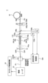
図1は、第一の実施形態にかかるレーザ光出力装置1の構成を示す図である。図2は、第一の実施形態にかかる波長変更部14の平面図である。図3は、第一の実施形態にかかる第一パルスP1、第二パルス(波長変換前)P2a、第二パルス(波長変換後)P2b、第三パルスP3のタイミングチャートである。なお、図3においては、波長に応じて、パルスを示す線の太さおよび線の種類(実線または破線)を変えて図示している。
First embodiment Fig. 1 is a diagram showing the configuration of a laser
第一の実施形態にかかるレーザ光出力装置1は、励起レーザ(パルスレーザ出力部)10、音響光学変調器(光路決定部)(AOM)12、波長変更部(PPLN)14、ミラー15、ダイクロイックミラー(合波器)(DCM)16、フィルタ(F)172、174、光ファイバ(MMF)18、タイミング制御回路(タイミング制御部)19、回折効率制御部(パワー比変更信号付与部)120、ハーフミラー130a、130b、フォトダイオード(出力測定部)(PD)132a、132bを備える。
The laser
励起レーザ(パルスレーザ出力部)10は、所定の波長W1[nm]のレーザ光を、所定の周波数(例えば、2kHz)の第一パルスP1(図3参照)として出力する。励起レーザ10は、例えば、Yb:YAGレーザである。
The excitation laser (pulse laser output unit) 10 outputs laser light of a predetermined wavelength W1 [nm] as a first pulse P1 (see FIG. 3) of a predetermined frequency (e.g., 2 kHz). The
音響光学変調器(光路決定部)(AOM)12は、第一パルスP1を受け、第一パルスP1の一つずつについて2つの光路OP1、OP2のいずれか一つ以上に光路を決定して出力する。なお、2つの光路OP1、OP2は、それぞれ、音響光学変調器12の0次光の光路および1次光の光路である。音響光学変調器12の回折効率ηが0の場合は、第一パルスP1は、光路OP1のみを進行する。回折効率ηが0を超える場合は、第一パルスP1は、光路OP1および光路OP2を進行する。音響光学変調器12が受けた第一パルスP1のパワーをIとすると、光路OP1にはパワーI・(1-η)のパルスが進行し、光路OP2にはパワーI・ηのパルスが進行する。
The acousto-optic modulator (optical path determination unit) (AOM) 12 receives the first pulse P1 and determines one or more of two optical paths OP1 and OP2 for each first pulse P1 and outputs it. The two optical paths OP1 and OP2 are the optical paths of the zeroth order light and the first order light of the acousto-
このように、音響光学変調器(光路決定部)(AOM)12は、進行光であって2つの光路OP1、OP2のうちの一方OP1を進行するものの第一パワーI・(1-η)と、進行光であって2つの光路OP1、OP2のうちの他方OP2を進行するものの第二パワーI・ηとの比であるパワー比(1-η:η)を変更することができる。なお、進行光とは、2つの光路OP1、OP2の各々を進行した光である。 In this way, the acousto-optical modulator (optical path determination unit) (AOM) 12 can change the power ratio (1-η:η), which is the ratio between the first power I·(1-η) of the traveling light traveling along one of the two optical paths OP1, OP2, OP1, and the second power I·η of the traveling light traveling along the other of the two optical paths OP1, OP2. Note that traveling light is light that has traveled along each of the two optical paths OP1, OP2.
音響光学変調器12には、回折効率制御部(パワー比変更信号付与部)120から回折効率制御信号が与えられる。回折効率ηは、回折効率制御信号のパワーPにより変化する。回折効率制御信号のパワーPは、0以上Pmax以下である。回折効率制御信号は、図示省略したトランスデューサにより、電気信号から音響波に変化して、音響光学変調器12に与えられる。
The acousto-
図6は、回折効率制御信号のパワーPと、回折効率ηとの関係を示す図である。回折効率制御信号のパワーPが0[W]の場合、回折効率η=0となる。0<P<P0において、回折効率ηは単調増加する。P=P0のときに、ηは最大値ηmaxをとる。P0<P<Pmaxにおいて、回折効率ηは単調減少する。 Figure 6 shows the relationship between the power P of the diffraction efficiency control signal and the diffraction efficiency η. When the power P of the diffraction efficiency control signal is 0 [W], the diffraction efficiency η = 0. When 0 < P < P0, the diffraction efficiency η increases monotonically. When P = P0, η has a maximum value ηmax. When P0 < P < Pmax, the diffraction efficiency η decreases monotonically.
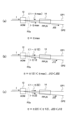
図15は、波長変更部(PPLN)14の出力が光路OP1から出力される場合の第一パワーI・(1-η)および第二パワーI・ηを示す図である。図16は、波長変更部(PPLN)14の出力が光路OP2から出力される場合の第一パワーI・(1-η)および第二パワーI・ηを示す図である。 Figure 15 is a diagram showing the first power I·(1-η) and the second power I·η when the output of the wavelength changing unit (PPLN) 14 is output from the optical path OP1. Figure 16 is a diagram showing the first power I·(1-η) and the second power I·η when the output of the wavelength changing unit (PPLN) 14 is output from the optical path OP2.
図15を参照して、回折効率η=0(図15(a)参照)の場合、第一パワーはI、第二パワーは0となる。回折効率η=η11(>0)(図15(b)参照)の場合、第一パワーはI(1-η11)、第二パワーはI・η11となる。回折効率η=η21(>η11)(図15(c)参照)の場合、第一パワーはI(1-η21)、第二パワーはI・η21となる。このように、回折効率ηが増加するにつれて、第一パワーが減少していく。 With reference to Figure 15, when the diffraction efficiency η = 0 (see Figure 15(a)), the first power is I and the second power is 0. When the diffraction efficiency η = η11 (> 0) (see Figure 15(b)), the first power is I (1 - η11) and the second power is I · η11. When the diffraction efficiency η = η21 (> η11) (see Figure 15(c)), the first power is I (1 - η21) and the second power is I · η21. In this way, as the diffraction efficiency η increases, the first power decreases.
図16を参照して、回折効率η=ηmax(図16(a)参照)の場合、第一パワーはI(1-ηmax)、第二パワーはI・ηmaxとなる。回折効率η=η12(<ηmax)(図16(b)参照)の場合、第一パワーはI(1-η12)、第二パワーはI・η12となる。回折効率η=η22(<η12)(図16(c)参照)の場合、第一パワーはI(1-η22)、第二パワーはI・η22となる。このように、回折効率ηが減少するにつれて、第二パワーが減少していく。 With reference to Figure 16, when the diffraction efficiency η = ηmax (see Figure 16(a)), the first power is I(1-ηmax) and the second power is I·ηmax. When the diffraction efficiency η = η12 (<ηmax) (see Figure 16(b)), the first power is I(1-η12) and the second power is I·η12. When the diffraction efficiency η = η22 (<η12) (see Figure 16(c)), the first power is I(1-η22) and the second power is I·η22. In this way, as the diffraction efficiency η decreases, the second power decreases.
音響光学変調器12と波長変更部(PPLN)14との間に図示省略した光減衰器を設けてもよい。
An optical attenuator (not shown) may be provided between the acousto-
波長変更部(PPLN)14は、2つの光路OP1、OP2の各々を進行した進行光(である第二パルスP2a)を受け、進行光のパワーが発振閾値(後述する)を超えた場合に、それぞれ異なった波長に変更して出力する。波長変更部14の出力が、第二パルス(波長変換後)P2bである。なお、波長変更部(PPLN)14は、PPLNである。また、波長変更部14は、OPO(光パラメトリック発振)またはOPG(光パラメトリック発生)である。
The wavelength changing unit (PPLN) 14 receives the traveling light (second pulse P2a) that has traveled through each of the two optical paths OP1 and OP2, and when the power of the traveling light exceeds an oscillation threshold (described later), it changes the wavelength to a different wavelength and outputs it. The output of the
図9は、波長変更部(PPLN)14の励起光エネルギとシグナル光エネルギとの関係を示す図である。ただし、励起光は光路OP1、OP2から与えられ、シグナル光は光路OP1、OP2から出力される。すると、光路OP1から与えられる励起光(進行光)は音響光学変調器12の0次光であり、この励起光により生じるシグナル光(波長変更部14の出力)が光路OP1から出力される。また、光路OP2から与えられる励起光(進行光)は音響光学変調器12の1次光であり、この励起光により生じるシグナル光(波長変更部14の出力)が光路OP2から出力される。
Figure 9 is a diagram showing the relationship between the excitation light energy and the signal light energy of the wavelength changing unit (PPLN) 14. However, the excitation light is provided from the optical paths OP1 and OP2, and the signal light is output from the optical paths OP1 and OP2. Then, the excitation light (traveling light) provided from the optical path OP1 is the zeroth order light of the acousto-
波長変更部14は、OPOまたはOPGであるため、発振閾値が存在する。すなわち、励起光エネルギ(進行光のパワー)が発振閾値を超えると、シグナル光(波長変更部14の出力)が出力される。励起光エネルギが発振閾値を超えている場合、励起光エネルギが大きくなれば、シグナル光のエネルギも増大する。
Because the
なお、光路OP1から与えられる励起光(0次光)の発振閾値は、光路OP2から与えられる励起光(1次光)の発振閾値よりも大きい。ただし、これは一例に過ぎず、励起光(0次光)の発振閾値が、励起光(1次光)の発振閾値よりも小さい場合もあり得る。また、励起光(0次光)の発振閾値が、励起光(1次光)の発振閾値と等しい場合もあり得る。 The oscillation threshold of the excitation light (zeroth order light) provided from optical path OP1 is greater than the oscillation threshold of the excitation light (first order light) provided from optical path OP2. However, this is merely one example, and the oscillation threshold of the excitation light (zeroth order light) may be smaller than the oscillation threshold of the excitation light (first order light). Also, the oscillation threshold of the excitation light (zeroth order light) may be equal to the oscillation threshold of the excitation light (first order light).
なお、上記のように、光路OP1、OP2ごとに、発振閾値が定まっている。 As mentioned above, the oscillation threshold is determined for each optical path OP1 and OP2.
音響光学変調器12は、進行光のうちいずれか一つの光路(OP1またはOP2)を進行した進行光のみのパワー(第一パワーI・(1-η)または第二パワーI・η)が、発振閾値を超えるようにする。
The acousto-
例えば、図15に示すような場合は、光路OP1を進行した進行光のみのパワー(第一パワーI・(1-η))が、発振閾値を超えるようにする。 For example, in the case shown in FIG. 15, the power of only the traveling light that has traveled along optical path OP1 (first power I·(1-η)) is made to exceed the oscillation threshold.
回折効率η=0(図15(a)参照)の場合、第一パワーIが発振閾値を超え、波長変更部14の出力はJ01となり、光路OP1より出力される。第二パワー0は発振閾値未満であるため、波長変更部14の出力が光路OP2より出力されることはない。
When the diffraction efficiency η = 0 (see FIG. 15(a)), the first power I exceeds the oscillation threshold, and the output of the
回折効率η=η11(>0)(図15(b)参照)の場合、第一パワーはI(1-η11)、第二パワーはI・η11となる。第一パワーI(1-η11)が発振閾値を超え、波長変更部14の出力はJ11となり、光路OP1より出力される。なお、回折効率η=0の場合に比べて、第一パワーがI・η11だけ小さくなるため、波長変更部14の出力J11もJ01より小さくなる。また、第二パワーI・η11は発振閾値未満であるため、波長変更部14の出力が光路OP2より出力されることはない。
When the diffraction efficiency η = η11 (> 0) (see Figure 15 (b)), the first power is I (1 - η11) and the second power is I · η11. The first power I (1 - η11) exceeds the oscillation threshold, and the output of the
回折効率η=η21(>η11)(図15(c)参照)の場合、第一パワーはI(1-η21)、第二パワーはI・η21となる。第一パワーI(1-η21)が発振閾値を超え、波長変更部14の出力はJ21となり、光路OP1より出力される。なお、回折効率η=η11の場合に比べて、第一パワーがI・(η21-η11)だけ小さくなるため、波長変更部14の出力J21もJ11より小さくなる。また、第二パワーI・η21は発振閾値未満であるため、波長変更部14の出力が光路OP2より出力されることはない。
When the diffraction efficiency η = η21 (> η11) (see Figure 15 (c)), the first power is I (1 - η21) and the second power is I · η21. The first power I (1 - η21) exceeds the oscillation threshold, and the output of the
このように、音響光学変調器12は、第一パワーI・(1-η)が発振閾値を超える場合に、パワー比(1-η:η)を二種類以上とることができるようする。例えば、パワー比を、1:0(図15(a)参照)、1-η11:η11(図15(b)参照)、1-η21:η21(図15(c)参照)とすることができる。これにより、波長変更部14の出力をJ01(図15(a)参照)からJ11(図15(b)参照)へ、J11(図15(b)参照)からJ21(図15(c)参照)へと減衰させることができる。
In this way, the acousto-
パワー比は最低二種類とることができればよく、例えば、パワー比を、1-η11:η11(図15(b)参照)、1-η21:η21(図15(c)参照)とすることも考えられる。これにより、波長変更部14の出力をJ11(図15(b)参照)からJ21(図15(c)参照)へと減衰させることができる。
It is sufficient if there are at least two types of power ratios; for example, the power ratio can be 1-η11:η11 (see FIG. 15(b)) or 1-η21:η21 (see FIG. 15(c)). This allows the output of the
例えば、図16に示すような場合は、光路OP2を進行した進行光のみのパワー(第二パワーI・η)が、発振閾値を超えるようにする。 For example, in the case shown in FIG. 16, the power of only the traveling light that has traveled along optical path OP2 (second power I·η) is made to exceed the oscillation threshold.
回折効率η=ηmax(図16(a)参照)の場合、第二パワーはI・ηmaxが発振閾値を超え、波長変更部14の出力はJ02となり、光路OP2より出力される。第一パワーI(1-ηmax)は発振閾値未満であるため、波長変更部14の出力が光路OP1より出力されることはない。
When the diffraction efficiency η = ηmax (see Figure 16 (a)), the second power I · ηmax exceeds the oscillation threshold, and the output of the
回折効率η=η12(<ηmax)(図16(b)参照)の場合、第一パワーはI(1-η12)、第二パワーはI・η12となる。第二パワーI・η12が発振閾値を超え、波長変更部14の出力はJ21となり、光路OP2より出力される。なお、回折効率η=ηmaxの場合に比べて、第二パワーがI・(ηmax-η12)だけ小さくなるため、波長変更部14の出力J12もJ02より小さくなる。また、第一パワーI(1-η12)は発振閾値未満であるため、波長変更部14の出力が光路OP1より出力されることはない。
When the diffraction efficiency η = η12 (< ηmax) (see Figure 16 (b)), the first power is I (1 - η12) and the second power is I · η12. The second power I · η12 exceeds the oscillation threshold, and the output of the
回折効率η=η22(<η12)(図16(c)参照)の場合、第一パワーはI(1-η22)、第二パワーはI・η22となる。第二パワーI・η22が発振閾値を超え、波長変更部14の出力はJ22となり、光路OP2より出力される。なお、回折効率η=η12の場合に比べて、第二パワーがI・(η12-η22)だけ小さくなるため、波長変更部14の出力J22もJ12より小さくなる。また、第一パワーI(1-η22)は発振閾値未満であるため、波長変更部14の出力が光路OP1より出力されることはない。
When the diffraction efficiency η = η22 (< η12) (see Figure 16 (c)), the first power is I (1 - η22) and the second power is I · η22. The second power I · η22 exceeds the oscillation threshold, and the output of the
このように、音響光学変調器12は、第二パワーI・ηが発振閾値を超える場合に、パワー比(1-η:η)を二種類以上とることができるようする。例えば、パワー比を、1-ηmax:ηmax(図16(a)参照)、1-η12:η12(図16(b)参照)、1-η22:η22(図16(c)参照)とすることができる。これにより、波長変更部14の出力をJ02(図16(a)参照)からJ12(図16(b)参照)へ、J12(図16(b)参照)からJ22(図16(c)参照)へと減衰させることができる。
In this way, the acousto-
パワー比は最低二種類とることができればよく、例えば、パワー比を、1-η12:η12(図16(b)参照)、1-η22:η22(図16(c)参照)とすることも考えられる。これにより、波長変更部14の出力をJ12(図16(b)参照)からJ22(図16(c)参照)へと減衰させることができる。
It is sufficient if there are at least two types of power ratios; for example, the power ratio can be 1-η12:η12 (see FIG. 16(b)) or 1-η22:η22 (see FIG. 16(c)). This allows the output of the
ここで、図1および図3を参照して、音響光学変調器12が第一パルスP1の奇数番目(1、3、…番目)のパルスを受けた時点では、光路OP1を進行した進行光のみのパワー(第一パワーI・(1-η))が、発振閾値を超えるようにする。光路OP2を進行した進行光のパワー(第二パワーI・η)は発振閾値未満となる。例えば、音響光学変調器12が第一パルスP1の1番目のパルスを受けた時点では、パワー比を1-η11:η11(図15(b)参照)とする。音響光学変調器12が第一パルスP1の3番目のパルスを受けた時点では、パワー比を1-η21:η21(図15(c)参照)とする。
Now, referring to FIG. 1 and FIG. 3, when the acousto-
また、音響光学変調器12が第一パルスP1の偶数番目(2、4、…番目)のパルスを受けた時点では、光路OP2を進行した進行光のみのパワー(第二パワーI・η)が、発振閾値を超えるようにする。光路OP1を進行した進行光のパワー(第一パワーI・(1-η))は発振閾値未満となる。例えば、音響光学変調器12が第一パルスP1の2番目のパルスを受けた時点では、パワー比を1-η12:η12(図16(b)参照)とする。音響光学変調器12が第一パルスP1の4番目のパルスを受けた時点では、パワー比を1-η22:η22(図16(c)参照)とする。
In addition, when the acousto-
これにより、音響光学変調器12は、複数の光路OP1、OP2の各々から、所定の周波数(例えば、2kHz)を複数の光路の個数(2個)で割った値の周波数(1kHz)を有し、かつそれぞれ位相が180度異なるパルスである第二パルス(波長変換前)P2aを出力する(ただし、発振閾値未満のパルスを無視する)。
As a result, the acousto-
タイミング制御回路(タイミング制御部)19は、音響光学変調器(光路決定部)12の出力を、第一パルスP1の出力のタイミングに合わせる。タイミングを合わせた結果は、図3を参照して上述したとおりである。なお、タイミング制御回路19は、励起レーザ(パルスレーザ出力部)10から、第一パルスP1の出力のタイミングに同期した信号を受け、この信号に基づき、音響光学変調器12の出力タイミングを制御する。
The timing control circuit (timing control section) 19 synchronizes the output of the acousto-optical modulator (optical path determination section) 12 with the timing of the output of the first pulse P1. The result of the timing synchronization is as described above with reference to FIG. 3. The
図3を参照して、波長変更部14は、第二パルスP2aのうち光路OP1を進行したもの(波長W1[nm])(発振閾値を超えている1、3、…番目のパルス)を受けて、第二パルスP2b(波長W2[nm])に変換する。ただし、第二パルスP2aのうち光路OP1を進行したもの(波長W1[nm])(発振閾値未満の2、4、…番目のパルス)を受けても、第二パルスP2b(波長W2[nm])を出力することはない。
Referring to FIG. 3, the
また、波長変更部14は、第二パルスP2aのうち光路OP2を進行したもの(波長W1[nm])(発振閾値を超えている2、4、…番目のパルス)を受けて、第二パルスP2b(波長W3[nm])に変換する。ただし、第二パルスP2aのうち光路OP2を進行したもの(波長W1[nm])(発振閾値未満の1、3、…番目のパルス)を受けても、第二パルスP2b(波長W2[nm])を出力することはない。
The
図10は、回折効率制御信号のパワーPと、第二パルスP2bのパワーとの対応関係を示す図である。回折効率制御信号のパワーPが0のときは、回折効率η=0であり(図6参照)、第二パルスP2b(光路OP1を進行するもの)のパワーはJ01となる(図15(a)参照)。パワーPが増大するにつれて、回折効率ηが増加し(図6参照)、第二パルスP2b(光路OP1を進行するもの)のパワーは減少していく(図15参照)。やがて、第二パルスP2a(光路OP1を進行したもの)が発振閾値以下となり、第二パルスP2b(光路OP1を進行するもの)は出力されなくなる。 Figure 10 is a diagram showing the correspondence relationship between the power P of the diffraction efficiency control signal and the power of the second pulse P2b. When the power P of the diffraction efficiency control signal is 0, the diffraction efficiency η = 0 (see Figure 6), and the power of the second pulse P2b (traveling along the optical path OP1) is J01 (see Figure 15 (a)). As the power P increases, the diffraction efficiency η increases (see Figure 6), and the power of the second pulse P2b (traveling along the optical path OP1) decreases (see Figure 15). Eventually, the second pulse P2a (traveling along the optical path OP1) falls below the oscillation threshold, and the second pulse P2b (traveling along the optical path OP1) is no longer output.
また、パワーPが増大するにつれて、回折効率ηが増加し(図6参照)、第二パルスP2a(光路OP2を進行したもの)が発振閾値を超えるようになり、第二パルスP2b(光路OP2を進行するもの)が出力されるようになる(図16参照)。 In addition, as the power P increases, the diffraction efficiency η increases (see FIG. 6), the second pulse P2a (which travels along the optical path OP2) exceeds the oscillation threshold, and the second pulse P2b (which travels along the optical path OP2) is output (see FIG. 16).
第二パルスP2bが光路OP1のみを進行する(光路OP2は進行しない)場合の、第二パルスP2bのパワーの範囲を出力範囲1という。光路OP1のみを進行する第二パルスP2bのパワーを、出力範囲1内で調整できる。
The range of the power of the second pulse P2b when the second pulse P2b travels only through optical path OP1 (and not through optical path OP2) is called
第二パルスP2bが光路OP2のみを進行する(光路OP1は進行しない)場合の、第二パルスP2bのパワーの範囲を出力範囲2という。光路OP2のみを進行する第二パルスP2bのパワーを、出力範囲2内で調整できる。 The range of the power of the second pulse P2b when the second pulse P2b travels only through optical path OP2 (and not through optical path OP1) is called output range 2. The power of the second pulse P2b traveling only through optical path OP2 can be adjusted within output range 2.
図2を参照して、波長変更部14は、LN結晶基板142、分極反転部144を有する。なお、図2においては、図示の便宜上、図1とは異なり、LN結晶基板142のx軸方向を紙面の横方向とを平行に図示している。
Referring to FIG. 2, the
分極反転部144は、進行光(である第二パルスP2a)が伝播するものである。分極反転部144は、光路OP1を進行する第二パルスP2aが伝播するものと、光路OP2を進行する第二パルスP2aが伝播するものとがある。なお、分極反転部144は、図2おいては、PPLN(周期分極反転ニオブ酸リチウム)であるが、これに限らず、例えば、PPLT(リチウムタンタレート)またはPPKTPでもよい。
The
光路OP1を進行する第二パルスP2aが伝播する分極反転部144は、所定の間隔D1をあけて配置されている。光路OP2を進行する第二パルスP2aが伝播する分極反転部144は、所定の間隔D2をあけて配置されている。所定の間隔は進行光ごとに異なる。すなわち、所定の間隔D1と、所定の間隔D2とは異なる。
The
LN結晶基板142には、分極反転部144が形成されている。LN結晶基板142は、ただ一つであり、分極反転部144の全てが形成されている。なお、第一の実施形態においては、LN結晶基板142は、LN結晶基板でなくとも、非線形光学結晶基板であればよい。他の実施形態においても同様に、LN結晶基板にかえて、非線形光学結晶基板を使用できる。
The
光路OP1を進行する第二パルスP2aが伝播する分極反転部144の図心144cは、LN結晶基板142のx軸に平行な直線上に配置されている。光路OP2を進行する第二パルスP2aが伝播する分極反転部144の図心144cも、LN結晶基板142のx軸に平行な直線上に配置されている。なお、分極反転部144の図心144cは、分極反転部144に均一に重力が作用しているとした場合の重心と一致する。
The
ミラー15は、第二パルス(波長変換後)P2bのうち、光路OP2を進行したものを受け、ダイクロイックミラー16に向けて反射する。
ダイクロイックミラー(合波器)(DCM)16は、波長変更部14の出力する第二パルス(波長変換後)P2bのうち、光路OP1を進行したものを、波長変更部14から受ける。ダイクロイックミラー16は、さらに、波長変更部14の出力する第二パルス(波長変換後)P2bのうち、光路OP2を進行したものを、ミラー15から受ける。さらに、ダイクロイックミラー16は、波長変更部14の出力する第二パルス(波長変換後)P2bのうち、光路OP1を進行したものと、光路OP2を進行したものとを合波し、所定の周波数(2kHz)を有する第三パルスP3を出力する。
The dichroic mirror (combiner) (DCM) 16 receives from the
ただし、波長変更部14の出力には、励起レーザ10の出力する波長W1[nm]のレーザ光(励起光)と、波長変更部14によって生じる赤外域のアイドラ光とが混入している。なお、レーザ光(励起光)を波長変更部14に与えると、光パラメトリック発生により、シグナル光と上述のアイドラ光とが生じる。シグナル光が、波長変更部14の出力(第二パルス(波長変換後)P2b)である(他の実施形態の波長変更部においても同様)。
However, the output of the
フィルタ(F)172、174は、それぞれ、波長変更部14の出力する第二パルス(波長変換後)P2bのうち、光路OP1、OP2を進行したものから、ポンプ光およびアイドラ光を除去して、ダイクロイックミラー16、ミラー15に出力する。なお、ポンプ光およびアイドラ光がフォトダイオード132a、132bに入らないようにするために、フィルタ172、174は、それぞれ、ハーフミラー130a、130bと波長変更部14との間に配置されている。
The filters (F) 172 and 174 remove the pump light and idler light from the second pulse (after wavelength conversion) P2b output by the
光ファイバ(MMF)18は、ダイクロイックミラー16の出力する第三パルスP3をその一端で受け、他端から出力する。
The optical fiber (MMF) 18 receives the third pulse P3 output from the
ハーフミラー130a、130bは、それぞれ、波長変更部14の出力する第二パルス(波長変換後)P2bのうち、光路OP1、OP2を進行したものの一部を反射して、フォトダイオード(出力測定部)(PD)132a、132bに与える。
The half mirrors 130a and 130b each reflect a portion of the second pulse (after wavelength conversion) P2b output by the
フォトダイオード(出力測定部)(PD)132a、132bは、それぞれ、ハーフミラー130a、130bを介して受けた波長変更部14の出力を測定する。
Photodiodes (output measuring units) (PD) 132a and 132b measure the output of the
回折効率制御部(パワー比変更信号付与部)120は、音響光学変調器(光路決定部)(AOM)12に、回折効率制御信号(パワー比変更信号)を与える。回折効率制御信号により、回折効率ηが変動し、ひいては、パワー比(1-η:η)が変動する。 The diffraction efficiency control unit (power ratio change signal providing unit) 120 provides a diffraction efficiency control signal (power ratio change signal) to the acousto-optic modulator (optical path determining unit) (AOM) 12. The diffraction efficiency control signal changes the diffraction efficiency η, and thus the power ratio (1-η:η).
図7は、回折効率制御部120の構成を示す機能ブロック図である。回折効率制御部120は、搬送波源122、変調信号出力部124、ミキサ(混合器)126、アンプ(振幅変更器)128a、128bを有する。
Figure 7 is a functional block diagram showing the configuration of the diffraction
搬送波源122は、搬送波を出力する。変調信号出力部124は、電圧が可変な変調信号を出力する。ミキサ(混合器)126は、搬送波と、変調信号とを混合して、被変調信号を出力する。ミキサ126は、LOポート、IFポート、RFポートを有している。例えば、LOポートには搬送波を与え、IFポートには変調信号を与え、RFポートから被変調信号を出力するようにすることが考えられる。アンプ(振幅変更器)128a、128bは、被変調信号の振幅を変更して回折効率制御信号(パワー比変更信号)を出力する。
The
図8は、変調信号の電圧と、回折効率制御信号のパワーPとの対応関係を示す図である。変調信号の電圧が0から増加するにしたがい、回折効率制御信号のパワーPも0からPmaxまで増加する。 Figure 8 shows the relationship between the voltage of the modulation signal and the power P of the diffraction efficiency control signal. As the voltage of the modulation signal increases from 0, the power P of the diffraction efficiency control signal also increases from 0 to Pmax.
このように、変調信号の電圧を変更することにより、回折効率制御信号のパワーP(パワー比変更信号の大きさ)を変更することができる。例えば、回折効率制御部(パワー比変更信号付与部)120の変調信号出力部124が、フォトダイオード(出力測定部)(PD)132a、132bの測定結果に基づき、回折効率制御信号のパワーP(パワー比変更信号の大きさ)の大きさを変更し、回折効率制御信号のパワーP(パワー比変更信号の大きさ)を変更する。
In this way, by changing the voltage of the modulation signal, it is possible to change the power P (magnitude of the power ratio change signal) of the diffraction efficiency control signal. For example, the modulation
次に、第一の実施形態の動作を説明する。 Next, the operation of the first embodiment will be described.
まず、励起レーザ10が、所定の波長W1[nm]のレーザ光を、所定の周波数(例えば、2kHz)の第一パルスP1(図3参照)として出力する。第一パルスP1は、音響光学変調器12に与えられる。タイミング制御回路19が、音響光学変調器12の出力タイミング(図3参照)を制御する。
First, the
また、回折効率制御部120が、回折効率制御信号を、音響光学変調器12に与えて、回折効率ηを調整する(図6参照)。
The diffraction
音響光学変調器12が、第一パルスP1の奇数番目(1、3、…番目)のパルスを受けた時点では、光路OP1を進行した進行光のみのパワー(第一パワーI・(1-η))が、発振閾値を超えるようにする。よって、光路OP1を進行する進行光は、所定の周波数(例えば、2kHz)を複数の光路の個数(2個)で割った値の周波数(1kHz)を有する第二パルス(波長変換前)P2aとなる(ただし、発振閾値未満のパルスを無視する)。
When the acousto-
音響光学変調器12が、第一パルスP1の偶数番目(2、4、…番目)のパルスを受けた時点では、光路OP2を進行した進行光のみのパワー(第二パワーI・η)が、発振閾値を超えるようにする。よって、光路OP2を進行する進行光は、所定の周波数(例えば、2kHz)を複数の光路の個数(2個)で割った値の周波数(1kHz)を有する第二パルス(波長変換前)P2aとなる(ただし、発振閾値未満のパルスを無視する)。
When the acousto-
しかも、光路OP1を進行する進行光(第二パルス(波長変換前)P2a)の位相と、光路OP2を進行する進行光(第二パルス(波長変換前)P2a)の位相とは180度異なる(ただし、発振閾値未満のパルスを無視する)。 In addition, the phase of the light (second pulse (before wavelength conversion) P2a) traveling along optical path OP1 differs by 180 degrees from the phase of the light (second pulse (before wavelength conversion) P2a) traveling along optical path OP2 (however, pulses below the oscillation threshold are ignored).
光路OP1を進行する進行光(第二パルス(波長変換前)P2a:波長W1[nm])(ただし、発振閾値未満のパルスを無視する)は、波長変更部14において所定の間隔D1をあけて配置されている分極反転部144を伝播し、波長がW2[nm]に変換され、第二パルス(波長変換後)P2bとなり、ダイクロイックミラー16に与えられる。
The light traveling along the optical path OP1 (second pulse (before wavelength conversion) P2a: wavelength W1 [nm]) (however, pulses below the oscillation threshold are ignored) propagates through the
光路OP2を進行する進行光(第二パルス(波長変換前)P2a:波長W1[nm])(ただし、発振閾値未満のパルスを無視する)は、波長変更部14において所定の間隔D2をあけて配置されている分極反転部144を伝播し、波長がW3[nm]に変換され、第二パルス(波長変換後)P2bとなり、ミラー15により反射されてから、ダイクロイックミラー16に与えられる。
The traveling light (second pulse (before wavelength conversion) P2a: wavelength W1 [nm]) (however, pulses below the oscillation threshold are ignored) traveling along optical path OP2 propagates through
波長変更部14の出力する第二パルス(波長変換後)P2bのうち、波長W2[nm]のものと、波長W3[nm]のものとがダイクロイックミラー16により合波され、所定の周波数(2kHz)を有する第三パルスP3となる。
Of the second pulses (after wavelength conversion) P2b output by the
第三パルスP3は、光ファイバ18の一端に与えられ、他端から出力される。
The third pulse P3 is applied to one end of the
なお、波長変更部14の出力する第二パルス(波長変換後)P2bは、ハーフミラー130a、130bを介して、フォトダイオード(出力測定部)(PD)132a、132bに与えられる。フォトダイオード132a、132bの測定結果に応じて、回折効率制御部120が、音響光学変調器12に与える回折効率制御信号の大きさを決定する。
The second pulse (after wavelength conversion) P2b output by the
第一の実施形態によれば、第三パルスP3を、光ファイバ18から出力することができる。第三パルスP3は、波長W2[nm]のパルス光が照射されてから、すぐに(例えば、500マイクロ秒)別の波長W3[nm]のパルス光を照射されるものである。すなわち、第一の実施形態によれば、ある波長のパルス光を照射してから、すぐに別の波長のパルス光を照射することができる。
According to the first embodiment, the third pulse P3 can be output from the
また、第一の実施形態によれば、図15を参照して、光路OP2を進行した進行光のパワー(第二パワーI・η)を大きくしていくことで(ただし、発振閾値未満として、波長変更部14の出力が光路OP2から出力されないようにする)、光路OP1を進行した進行光のパワー(第一パワーI・(1-η))を小さくすることができ、これにより、波長変更部14の出力(光路OP1より)を減衰させることにより、レーザ光出力装置1の出力(第三パルスP3)の調整ができる。
Also, according to the first embodiment, referring to FIG. 15, by increasing the power (second power I·η) of the traveling light that has traveled through optical path OP2 (however, it is set below the oscillation threshold so that the output of the
さらに、第一の実施形態によれば、図16を参照して、光路OP1を進行した進行光のパワー(第一パワーI・(1-η))を大きくしていくことで(ただし、発振閾値未満として、波長変更部14の出力が光路OP1から出力されないようにする)、光路OP2を進行した進行光のパワー(第二パワーI・η)を小さくすることができ、これにより、波長変更部14の出力(光路OP2より)を減衰させることにより、レーザ光出力装置1の出力(第三パルスP3)の調整ができる。
Furthermore, according to the first embodiment, referring to FIG. 16, by increasing the power (first power I·(1-η)) of the traveling light that has traveled through optical path OP1 (however, below the oscillation threshold so that the output of the
このような波長変更部14の出力の減衰は、1/2波長板および偏光子を有する可変光アッテネータにおいて1/2波長板をモータにより回転させる場合に比べて(特許文献3を参照)、高速かつ小型の装置で行うことができる。
Such attenuation of the output of the
第一変形例
なお、第一の実施形態においては、分極反転部144の図心144cが、LN結晶基板142のx軸に平行な直線上に配置されているが(図2参照)、分極反転部144の図心144cの配置については、以下のような変形例が考えられる。
First Modified Example: In the first embodiment, the
図4は、第一の実施形態の第一変形例にかかる波長変更部14の平面図である。なお、図4においては、図示の便宜上、図1とは異なり、図2と同様に、LN結晶基板142のx軸方向を紙面の横方向とを平行に図示している。
Figure 4 is a plan view of the
図4を参照して、第一の実施形態の第一変形例にかかる波長変更部14においては、進行光(光路OP1を進行する第二パルスP2a)が伝播する分極反転部144が、所定の間隔D1をあけて配置されおり、その図心144cが進行光(光路OP1を進行する第二パルスP2a)の進行方向に平行な直線上(例えば、進行方向上)に配置されている。また、進行光(光路OP2を進行する第二パルスP2a)が伝播する分極反転部144が、所定の間隔D2をあけて配置されおり、その図心144cが進行光(光路OP2を進行する第二パルスP2a)の進行方向に平行な直線上(例えば、進行方向上)に配置されている。
Referring to FIG. 4, in the
上記のような第一の実施形態の第一変形例によれば、分極反転部144の縦の長さ(Y軸方向の長さ)を、第一の実施形態の場合に比べて、短くすることができる。
According to the first modification of the first embodiment described above, the vertical length (length in the Y-axis direction) of the
また、第一の実施形態においては、波長変更部14に分極反転部144を設けることとされているが(図2および図4参照)、分極反転部144を設けないで、進行光が伝播する非線形光学結晶を有する変形例も考えられる。例えば、波長変更部14を、BPM(複屈折位相整合)によるOPO(光パラメトリック発振)、SHG(第2高調波発生)またはTHG(第3高調波発生)などとすることができる。
In the first embodiment, the
第二変形例
なお、第一の実施形態においてはLN結晶基板142が一つしかないが、LN結晶基板を伝播する進行光ごとに設ける変形例が考えられる。
Second Modification Although there is only one
図5は、第一の実施形態の第二変形例にかかるレーザ光出力装置1の構成を示す図である。第一の実施形態と相違する部分は、ロンボイドプリズム131、波長変更部(PPLN)14a、14bであり、他の部分は第一の実施形態と同様であるので、説明を省略する。
Figure 5 is a diagram showing the configuration of a laser
ロンボイドプリズム131は、第二パルス(波長変換前)P2aのうち、光路OP2を進行したものを受け、光路を平行に、かつ光路OP1から離れるように変更する。
The
波長変更部(PPLN)14aは、第二パルスP2aのうち光路OP1を進行したもの(波長W1[nm])を音響光学変調器12から受けて、発振閾値を超えるもののみを第二パルスP2b(波長W2[nm])に変換する。波長変更部14aの構成は、図2または図4のうち、所定の間隔D1をあけて配置されている分極反転部144と、それが形成されているLN結晶基板142とに相当する。
The wavelength changing unit (PPLN) 14a receives the second pulse P2a (wavelength W1 [nm]) that has traveled through the optical path OP1 from the acousto-
波長変更部(PPLN)14bは、第二パルスP2aのうち光路OP2を進行したもの(波長W1[nm])をロンボイドプリズム131から受けて、発振閾値を超えるもののみを第二パルスP2b(波長W3[nm])に変換する。波長変更部14bの構成は、図2または図4のうち、所定の間隔D2をあけて配置されている分極反転部144と、それが形成されているLN結晶基板142とに相当する。
The wavelength changing unit (PPLN) 14b receives the second pulse P2a (wavelength W1 [nm]) that has traveled through the optical path OP2 from the
なお、波長変更部14aの有するLN結晶基板と、波長変更部14bの有するLN結晶基板とは別のものである。すなわち、波長変更部14aの有するLN結晶基板と、波長変更部14bの有するLN結晶基板とは、伝播する進行光(光路OP1を進行したものと、光路OP2を進行したもの)ごとに設けられている。
The LN crystal substrate of the
第一の実施形態の第二変形例によれば、LN結晶基板が、伝播する進行光(光路OP1を進行したものと、光路OP2を進行したもの)ごとに設けられているので、所定の間隔D1およびD2に応じた分極反転部144の製造条件を設定でき、波長変更部14a、14bの製造が容易となる。
According to the second modification of the first embodiment, an LN crystal substrate is provided for each propagating traveling light (that which has traveled along optical path OP1 and that which has traveled along optical path OP2), so that the manufacturing conditions of the
第三変形例
なお、第一の実施形態においては、ある波長W2[nm]の「一つ」のパルス光を照射してから、すぐに別の波長W3[nm]の「一つ」のパルス光を照射する(図3のP3参照)が、ある波長W2[nm]の「複数」のパルス光(所定時間範囲TR1内)を照射してから、すぐにある波長W3[nm]の「複数」のパルス光(所定時間範囲TR2内)を照射する(図11のP3参照)ような変形例が考えられる。
In the first embodiment, "one" pulsed light having a wavelength W2 [nm] is irradiated, and then "one" pulsed light having another wavelength W3 [nm] is irradiated immediately (see P3 in FIG. 3). However, a modification may be considered in which "multiple" pulsed lights having a wavelength W2 [nm] (within a predetermined time range TR1) are irradiated, and then "multiple" pulsed lights having a wavelength W3 [nm] (within a predetermined time range TR2) are irradiated immediately (see P3 in FIG. 11).
また、この変形例にかかるレーザ光出力装置1は、第一パルスP1の周波数が一定しない点が、第一パルスP1の周波数が一定である(例えば、2kHz)第一の実施形態と異なる。
In addition, the laser
図11は、第一の実施形態の第三変形例にかかる第一パルスP1、第二パルス(波長変換前)P2a、第二パルス(波長変換後)P2b、第三パルスP3のタイミングチャートである。なお、図11においては、波長に応じて、パルスを示す線の太さおよび線の種類(実線または破線)を変えて図示している。また、図11においては、回折効率η=η11、η12の場合を図示している。 Figure 11 is a timing chart of the first pulse P1, the second pulse (before wavelength conversion) P2a, the second pulse (after wavelength conversion) P2b, and the third pulse P3 according to the third modified example of the first embodiment. Note that in Figure 11, the thickness and type of the lines (solid lines or dashed lines) indicating the pulses are changed depending on the wavelength. Also, Figure 11 illustrates the cases where the diffraction efficiency η = η11 and η12.
励起レーザ(パルスレーザ出力部)10は、所定の波長W1[nm]のレーザ光を、第一パルスP1(図11参照)として出力する。励起レーザ10は、例えば、Yb:YAGレーザである。図11を参照して、第一パルスP1は、所定時間範囲TR1、TR2ごとに出力される疑似ランダム信号(例えば、M系列信号)である。なお、所定時間範囲TR1、TR2の長さは、M系列信号の1周期に相当する。また、第一パルスP1は疑似ランダム信号であるため、第一実施形態とは異なり、その周波数は一定していない。
The excitation laser (pulse laser output unit) 10 outputs laser light of a predetermined wavelength W1 [nm] as a first pulse P1 (see FIG. 11). The
音響光学変調器(光路決定部)(AOM)12は、第一パルスP1を受け、第一パルスP1の一つずつについて2つの光路OP1、OP2のいずれか一つ以上に光路を決定して出力する。 The acousto-optical modulator (optical path determining unit) (AOM) 12 receives the first pulse P1 and determines one or more of the two optical paths OP1 and OP2 for each first pulse P1 and outputs it.
例えば、図11を参照して、音響光学変調器12が、第一パルスP1の所定時間範囲TR1内の複数のパルスを受けた時点では、光路OP1を進行した進行光のみのパワー(第一パワーI・(1-η))が、発振閾値を超えるようにする。光路OP2を進行した進行光のパワー(第二パワーI・η)は発振閾値未満となる。例えば、音響光学変調器12が第一パルスP1の所定時間範囲TR1内の複数のパルスを受けた時点では、パワー比を1-η11:η11(図15(b)参照)とする。
For example, referring to FIG. 11, when the acousto-
また、音響光学変調器12が、第一パルスP1の所定時間範囲TR2内の複数のパルスを受けた時点では、光路OP2を進行した進行光のみのパワー(第二パワーI・η)が、発振閾値を超えるようにする。光路OP1を進行した進行光のパワー(第一パワーI・(1-η))は発振閾値未満となる。例えば、音響光学変調器12が第一パルスP1の所定時間範囲TR2内の複数のパルスを受けた時点では、パワー比を1-η12:η12(図16(b)参照)とする。
In addition, when the acousto-
これにより、音響光学変調器12は、第一パルスP1の内の所定時間範囲TR1、TR2内にある複数のパルスであり、かつそれぞれ所定時間範囲が異なる(重複しない)パルスである第二パルス(波長変換前)P2a(発振閾値を超えるもののみ)を、複数の光路OP1、OP2の各々から出力する。
As a result, the acousto-
すなわち、音響光学変調器12は、光路OP1から、第一パルスP1の内の所定時間範囲TR1内にある複数のパルスを出力する(図9のP2a(OP1)参照)。さらに、音響光学変調器12は、光路OP2から、第一パルスP1の内の所定時間範囲TR2内にある複数のパルスを出力する(図9のP2a(OP2)参照)。第二パルスP2aのうち光路OP1を進行したもの(P2a(OP1))(発振閾値を超えるもののみ)と、第二パルスP2aのうち光路OP2を進行したもの(P2a(OP2))(発振閾値を超えるもののみ)とは、所定時間範囲が異なる(重複しない)。
That is, the acousto-
波長変更部(PPLN)14は、複数の光路OP1、OP2の各々を進行した進行光(である第二パルスP2a)を受け、それぞれ異なった波長に変更して出力する。波長変更部14の出力が、第二パルス(波長変換後)P2bである。
The wavelength changing unit (PPLN) 14 receives the traveling light (second pulse P2a) that has traveled along each of the multiple optical paths OP1 and OP2, changes the wavelength to a different wavelength, and outputs it. The output of the
図11を参照して、波長変更部14は、第二パルスP2aのうち光路OP1を進行したもの(波長W1[nm])(発振閾値を超えるもののみ)を受けて、第二パルスP2b(波長W2[nm])に変換する。また、波長変更部14は、第二パルスP2aのうち光路OP2を進行したもの(波長W1[nm])(発振閾値を超えるもののみ)を受けて、第二パルスP2b(波長W3[nm])に変換する。
Referring to FIG. 11, the
第一の実施形態の第三変形例によれば、第三パルスP3を、光ファイバ18から出力することができる。第三パルスP3は、波長W2[nm]の複数のパルス光が照射されてから、すぐに別の波長W3[nm]の複数のパルス光を照射されるものである。すなわち、第一の実施形態の第三変形例によれば、ある波長のパルス光を照射してから、すぐに別の波長のパルス光を照射することができる。
According to the third modified example of the first embodiment, the third pulse P3 can be output from the
第二の実施形態
第二の実施形態にかかるにかかるレーザ光出力装置1は、第一の実施形態におけるダイクロイックミラー(合波器)(DCM)16にかえて、凸レンズ(平行化部)(L1)13、およびアクロマートレンズ(集束部)(L2)160を備えたものである。
Second Embodiment A laser
図12は、第二の実施形態にかかるレーザ光出力装置1の構成を示す図である。図13は、第二の実施形態にかかる波長変更部14の平面図である。
Figure 12 is a diagram showing the configuration of a laser
第二の実施形態にかかるレーザ光出力装置1は、励起レーザ(パルスレーザ出力部)10、音響光学変調器(光路決定部)(AOM)12、凸レンズ(平行化部)(L1)13、波長変更部(PPLN)14、アクロマートレンズ(集束部)(L2)160、フィルタ(F)172、174、光ファイバ(MMF)18、タイミング制御回路(タイミング制御部)19、回折効率制御部(パワー比変更信号付与部)120、ハーフミラー130a、130b、フォトダイオード(出力測定部)(PD)132a、132bを備える。以下、第一の実施形態と同様な部分は同一の符号を付して説明を省略する。
The laser
励起レーザ(パルスレーザ出力部)10、音響光学変調器(光路決定部)(AOM)12、フィルタ(F)172、174、タイミング制御回路(タイミング制御部)19、回折効率制御部(パワー比変更信号付与部)120、ハーフミラー130a、130b、フォトダイオード(出力測定部)(PD)132a、132bは、第一の実施形態と同様であり、説明を省略する。 The excitation laser (pulse laser output section) 10, acousto-optical modulator (optical path determination section) (AOM) 12, filters (F) 172, 174, timing control circuit (timing control section) 19, diffraction efficiency control section (power ratio change signal application section) 120, half mirrors 130a, 130b, and photodiodes (output measurement section) (PD) 132a, 132b are the same as in the first embodiment, and their explanation will be omitted.
凸レンズ(平行化部)(L1)13は、2つの光路OP1、OP2の各々を進行した進行光の進行方向を平行にする。なお、平行化部として、凸レンズ13にかえて、プリズムを用いることも可能である。
The convex lens (parallelizing section) (L1) 13 parallelizes the traveling direction of the light traveling along each of the two optical paths OP1 and OP2. Note that a prism can be used as the parallelizing section instead of the
なお、凸レンズ(平行化部)13の出力の間の距離の最大値をYmaxとすれば、Ymaxは、凸レンズ13からアクロマートレンズ16までに位置する光路OP1と光路OP2との間の距離となる(図13参照)。
If the maximum distance between the outputs of the convex lens (parallelization section) 13 is Ymax, then Ymax is the distance between optical paths OP1 and OP2 located from the
波長変更部(PPLN)14は、第一の実施形態と同様であるが、凸レンズ(平行化部)13の出力、すなわち2つの光路OP1、OP2の各々を進行した進行光が凸レンズ13を透過したもの(である第二パルスP2a)を受け、凸レンズ(平行化部)13の出力のパワーが発振閾値を超えた場合に、それぞれ異なった波長に変更して出力する。波長変更部14の出力が、第二パルス(波長変換後)P2bである。
The wavelength changing unit (PPLN) 14 is similar to that of the first embodiment, but receives the output of the convex lens (parallelizing unit) 13, i.e., the light traveling along each of the two optical paths OP1 and OP2 that is transmitted through the convex lens 13 (the second pulse P2a), and when the power of the output of the convex lens (parallelizing unit) 13 exceeds the oscillation threshold, it changes the wavelength to a different wavelength and outputs it. The output of the
なお、音響光学変調器12の出力のいずれか一つ(例えば、光路OP1を進行するもの)が、凸レンズ13の光軸を通過するようにしてもよい。この場合、凸レンズ13は、光路OP1を進行するものの進行方向を変えないが、光路OP2を進行するものの進行方向を変えて光路OP1と平行にする。
In addition, one of the outputs of the acousto-optical modulator 12 (for example, the one traveling along optical path OP1) may pass through the optical axis of the
図3を参照して、波長変更部14は、第二パルスP2aのうち光路OP1を進行したもの(波長W1[nm])を受けて、第二パルスP2b(波長W2[nm])に変換する(発振閾値を超えているもののみ)。また、波長変更部14は、第二パルスP2aのうち光路OP2を進行したもの(波長W1[nm])を受けて、第二パルスP2b(波長W3[nm])に変換する(発振閾値を超えているもののみ)。なお、波長変更部14の発振閾値については、第一の実施形態と同様であり、説明を省略する(図9参照)。
Referring to FIG. 3, the
図13を参照して、波長変更部14は、LN結晶基板142、分極反転部144を有する。なお、図2においては、図1と同様に、LN結晶基板142のX軸方向を紙面の横方向とを平行に図示している。
Referring to FIG. 13, the
分極反転部144は、凸レンズ13の出力(である第二パルスP2a)が伝播するものである。分極反転部144は、光路OP1を進行する第二パルスP2aが伝播するものと、光路OP2を進行する第二パルスP2aが伝播するものとがある。なお、分極反転部144は、図13おいては、PPLN(周期分極反転ニオブ酸リチウム)であるが、これに限らず、例えば、PPLT(リチウムタンタレート)またはPPKTPでもよい。
The
光路OP1を進行する第二パルスP2aが伝播する分極反転部144は、所定の間隔D1をあけて配置されている。光路OP2を進行する第二パルスP2aが伝播する分極反転部144は、所定の間隔D2をあけて配置されている。所定の間隔は凸レンズ13の出力ごとに異なる。すなわち、所定の間隔D1と、所定の間隔D2とは異なる。
The
LN結晶基板142には、分極反転部144が形成されている。LN結晶基板142は、ただ一つであり、分極反転部144の全てが形成されている。なお、第二の実施形態においては、LN結晶基板142は、LN結晶基板でなくとも、非線形光学結晶基板であればよい。他の実施形態においても同様に、LN結晶基板にかえて、非線形光学結晶基板を使用できる。
The
光路OP1を進行する第二パルスP2aが伝播する分極反転部144の図心144cは、LN結晶基板142のX軸に平行な直線上に配置されている。光路OP2を進行する第二パルスP2aが伝播する分極反転部144の図心144cも、LN結晶基板142のX軸に平行な直線上に配置されている。なお、分極反転部144の図心144cは、分極反転部144に均一に重力が作用しているとした場合の重心と一致する。
The
なお、波長変更部14の出力には、第二パルスP2bの他にも、励起レーザ10の出力する波長W1[nm]のレーザ光(励起光)と、波長変更部14によって生じる赤外域のアイドラ光とが混入している。なお、レーザ光(励起光)を波長変更部14に与えると、光パラメトリック発生により、シグナル光と上述のアイドラ光とが生じる。シグナル光が、波長変更部14の出力(第二パルス(波長変換後)P2b)である(他の実施形態の波長変更部においても同様)。
In addition to the second pulse P2b, the output of the
アクロマートレンズ(集束部)(L2)160は、波長変更部14の出力を受けて集束する。アクロマートレンズ160は、凸レンズ160a、凹レンズ160bを有する。凸レンズ160aは凹レンズ160bよりも励起レーザ10に近く配置されている。凹レンズ160bの凹面に、凸レンズ160aの凸面が接している。
The achromatic lens (focusing section) (L2) 160 receives and focuses the output of the
アクロマートレンズ160は、第二パルスP2b(波長W2[nm])(光路OP1を進行したもの)と、第二パルスP2b(波長W3[nm])(光路OP2を進行したもの)との間の波長の違いによる焦点距離の違い(色収差)を少なくしたレンズである。 The achromatic lens 160 is a lens that reduces the difference in focal length (chromatic aberration) caused by the difference in wavelength between the second pulse P2b (wavelength W2 [nm]) (traveling along optical path OP1) and the second pulse P2b (wavelength W3 [nm]) (traveling along optical path OP2).
なお、波長W2[nm]と波長W3[nm]との差が小さい場合は、集束部として、アクロマートレンズ160にかえて、単一の凸レンズ160aを用いてもよい。 When the difference between wavelengths W2 [nm] and W3 [nm] is small, a single convex lens 160a may be used as the focusing section instead of the achromatic lens 160.
光ファイバ(MMF)18はコアを有し、コアは端面18Eを有する。光ファイバ18は、アクロマートレンズ160の出力を、コアの端面18Eで受ける。アクロマートレンズ160が、波長変更部14の出力を、コアの端面18Eに集束する。
The optical fiber (MMF) 18 has a core, and the core has an
波長変更部14の出力を、コアの端面18Eに集束させるためには、アクロマートレンズ160の焦点距離をfとし、光ファイバ18の開口数をNAとしたとき、NA>Ymax/(2f)であることが好ましい。
In order to focus the output of the
光ファイバ(MMF)18は、コアの端面18Eに集束された波長変更部14の出力(第三パルスP3)(図3参照)を、他端から出力する。
The optical fiber (MMF) 18 outputs the output (third pulse P3) of the
次に、第二の実施形態の動作を説明する。 Next, we will explain the operation of the second embodiment.
励起レーザ10、音響光学変調器12およびタイミング制御回路19に関する動作は、第一の実施形態と同様であり、説明を省略する。
The operation of the
光路OP1を進行する進行光は、凸レンズ13をその光軸方向にまっすぐ透過して、所定の周波数(例えば、2kHz)を複数の光路の個数(2個)で割った値の周波数(1kHz)を有する第二パルス(波長変換前)P2a(図3参照)となる(ただし、発振閾値未満のパルスを無視する)。
The light traveling along optical path OP1 passes straight through
光路OP2を進行する進行光は、凸レンズ13により進行方向を光路OP1と平行に変えながら凸レンズ13を透過して、所定の周波数(例えば、2kHz)を複数の光路の個数(2個)で割った値の周波数(1kHz)を有する第二パルス(波長変換前)P2a(図3参照)となる(ただし、発振閾値未満のパルスを無視する)。
The light traveling along optical path OP2 passes through
しかも、光路OP1を進行する進行光が凸レンズ13を透過したもの(第二パルス(波長変換前)P2a)の位相と、光路OP2を進行する進行光が凸レンズ13を透過したもの(第二パルス(波長変換前)P2a)の位相とは180度異なる(ただし、発振閾値未満のパルスを無視する)。 In addition, the phase of the light traveling along optical path OP1 that is transmitted through convex lens 13 (second pulse (before wavelength conversion) P2a) differs by 180 degrees from the phase of the light traveling along optical path OP2 that is transmitted through convex lens 13 (second pulse (before wavelength conversion) P2a) (however, pulses below the oscillation threshold are ignored).
光路OP1を進行する進行光が凸レンズ13を透過したもの(第二パルス(波長変換前)P2a:波長W1[nm])(ただし、発振閾値未満のパルスを無視する)は、波長変更部14において所定の間隔D1をあけて配置されている分極反転部144を伝播し、波長がW2[nm]に変換され、第二パルス(波長変換後)P2b(図3参照)となり、フィルタ172により、励起光およびアイドラ光が除去されて、アクロマートレンズ16に与えられる。
The light traveling along the optical path OP1 that passes through the convex lens 13 (second pulse (before wavelength conversion) P2a: wavelength W1 [nm]) (however, pulses below the oscillation threshold are ignored) propagates through the
光路OP2を進行する進行光が凸レンズ13を透過したもの(第二パルス(波長変換前)P2a:波長W1[nm])(ただし、発振閾値未満のパルスを無視する)は、波長変更部14において所定の間隔D2をあけて配置されている分極反転部144を伝播し、波長がW3[nm]に変換され、第二パルス(波長変換後)P2b(図3参照)となり、フィルタ174により、励起光およびアイドラ光が除去されて、アクロマートレンズ16に与えられる。
The light traveling along optical path OP2 that passes through convex lens 13 (second pulse (before wavelength conversion) P2a: wavelength W1 [nm]) (however, pulses below the oscillation threshold are ignored) propagates through
波長変更部14の出力する第二パルス(波長変換後)P2bのうち、波長W2[nm]のものと、波長W3[nm]のものとがアクロマートレンズ16により光ファイバ18のコアの端面18Eに集束され、所定の周波数(2kHz)を有する第三パルスP3(図3のP3と同じ波形である)となる。
Of the second pulses (after wavelength conversion) P2b output by the
第三パルスP3は、光ファイバ18の他端から出力される。
The third pulse P3 is output from the other end of the
ハーフミラー130a、130b、フォトダイオード(出力測定部)(PD)132a、132bおよび回折効率制御部120に関する動作は、第一の実施形態と同様であり、説明を省略する。
The operations of the half mirrors 130a and 130b, the photodiodes (output measurement units) (PD) 132a and 132b, and the diffraction
第二の実施形態によれば、第一の実施形態と同様な効果を奏する。 The second embodiment provides the same effects as the first embodiment.
しかも、第二の実施形態によれば、波長変更部14の出力する第二パルス(波長変換後)P2bのうち、波長W2[nm]のものと、波長W3[nm]のものとを合波する合波器(例えば、ダイクロイックミラー)が不要となる。ダイクロイックミラーは、光軸の調整および第二パルス(波長変換後)P2bの波長W2[nm]および波長W3[nm]の変更への対応が難しいので、ダイクロイックミラーを不要とすることで、労力の軽減を図ることができる。
Moreover, according to the second embodiment, there is no need for a multiplexer (e.g., a dichroic mirror) that multiplexes the second pulse (after wavelength conversion) P2b output by the
なお、第二の実施形態においては、第一の実施形態の第三変形例(図11参照)と同様に、ある波長W2[nm]の「複数」のパルス光(所定時間範囲TR1内)を照射してから、すぐにある波長W3[nm]の「複数」のパルス光(所定時間範囲TR2内)を照射するようにしてもよい。 In the second embodiment, as in the third modified example of the first embodiment (see FIG. 11), multiple pulsed lights (within a predetermined time range TR1) having a wavelength W2 [nm] may be irradiated, and then multiple pulsed lights (within a predetermined time range TR2) having a wavelength W3 [nm] may be irradiated immediately thereafter.
変形例
なお、第二の実施形態においてはLN結晶基板142が一つしかないが、LN結晶基板を伝播する進行光ごとに設ける変形例が考えられる。
Modifications Although there is only one
図14は、第二の実施形態の変形例にかかるレーザ光出力装置1の構成を示す図である。第二の実施形態と相違する部分は、波長変更部(PPLN)14a、14bであり、他の部分は第二の実施形態と同様であるので、説明を省略する。
Figure 14 is a diagram showing the configuration of a laser
波長変更部(PPLN)14aは、第二パルスP2aのうち光路OP1を進行したもの(波長W1[nm])を音響光学変調器12から凸レンズ13を介して受けて、発振閾値を超えるもののみを第二パルスP2b(波長W2[nm])に変換する。波長変更部14aの構成は、図13のうち、所定の間隔D1をあけて配置されている分極反転部144と、それが形成されているLN結晶基板142とに相当する。
The wavelength changing unit (PPLN) 14a receives the second pulse P2a (wavelength W1 [nm]) that has traveled along the optical path OP1 from the acousto-
波長変更部(PPLN)14bは、第二パルスP2aのうち光路OP2を進行したもの(波長W1[nm])を音響光学変調器12から凸レンズ13を介してから受けて、発振閾値を超えるもののみを第二パルスP2b(波長W3[nm])に変換する。波長変更部14bの構成は、図13のうち、所定の間隔D2をあけて配置されている分極反転部144と、それが形成されているLN結晶基板142とに相当する。
The wavelength changing unit (PPLN) 14b receives the second pulse P2a (wavelength W1 [nm]) that has traveled through the optical path OP2 from the acousto-
なお、波長変更部14aの有するLN結晶基板と、波長変更部14bの有するLN結晶基板とは別のものである。すなわち、波長変更部14aの有するLN結晶基板と、波長変更部14bの有するLN結晶基板とは、伝播する凸レンズ13の出力(光路OP1を進行したものと、光路OP2を進行したもの)ごとに設けられている。
The LN crystal substrate of the
第二の実施形態の変形例によれば、LN結晶基板が、伝播する進行光(光路OP1を進行したものと、光路OP2を進行したもの)ごとに設けられているので、所定の間隔D1およびD2に応じた分極反転部144の製造条件を設定でき、波長変更部14a、14bの製造が容易となる。
According to the modified example of the second embodiment, an LN crystal substrate is provided for each propagating traveling light (that which has traveled along optical path OP1 and that which has traveled along optical path OP2), so that the manufacturing conditions of the
第三の実施形態
第一および第二の実施形態にかかるレーザ光出力装置1においては、光路が2つ(光路OP1および光路OP2)設けられている。したがって、光ファイバ18の他端から出力される第三パルスの波長もW2およびW3の2種類となる。
In the laser
しかし、光路は2つを超えてもよい。第三の実施形態にかかるレーザ光出力装置1においては、光路が3つ(光路OP1、光路OP2および光路OP3)設けられており、この点が第一の実施形態と異なる。したがって、光ファイバ18の他端から出力される第三パルスの波長もW2、W3およびW4の3種類となる。
However, there may be more than two optical paths. In the laser
第三の実施形態にかかるレーザ光出力装置1は、光路決定部として2個の音響光学変調器(第一音響光学変調器(AOM)12aおよび第二音響光学変調器(AOM)12b)を用いる点が第一の実施形態にかかるレーザ光出力装置1と主に異なる。
The laser
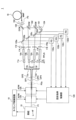
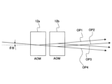
図17は、第三の実施形態にかかるレーザ光出力装置1の構成を示す図である。図18は、第三の実施形態にかかるレーザ光出力装置1における光路決定部(第一音響光学変調器(AOM)12aおよび第二音響光学変調器(AOM)12b)の近傍の拡大図である。
Figure 17 is a diagram showing the configuration of a laser
第三の実施形態にかかるレーザ光出力装置1は、励起レーザ(パルスレーザ出力部)10、光減衰器(ATT)11a、11b、11c、第一音響光学変調器(AOM)12a、第二音響光学変調器(AOM)12b、ロンボイドプリズム13a、13b、波長変更部(PPLN)14a、14b、14c、ミラー154、ダイクロイックミラー(合波器)(DCM)162、164、フィルタ(F)172、174、176、光ファイバ(MMF)18、タイミング制御回路(タイミング制御部)19、レンズ(L)192、回折効率制御部(パワー比変更信号付与部)120、ハーフミラー130a、130b、130c、フォトダイオード(出力測定部)(PD)132a、132b、132cを備える。以下、第一の実施形態と同様な部分は同一の符号を付して説明を省略する。
The laser
回折効率制御部(パワー比変更信号付与部)120、ハーフミラー130a、130b、フォトダイオード(出力測定部)(PD)132a、132bは、第一の実施形態と同様であり、説明を省略する。ただし、回折効率制御部120は、フォトダイオード(出力測定部)(PD)132a、132bおよび132cの測定結果に基づき、回折効率制御信号のパワーP(パワー比変更信号の大きさ)の大きさを変更し、回折効率制御信号のパワーP(パワー比変更信号の大きさ)を変更する。
The diffraction efficiency control unit (power ratio change signal providing unit) 120, half mirrors 130a, 130b, and photodiodes (output measurement units) (PD) 132a, 132b are the same as in the first embodiment, and a description thereof will be omitted. However, the diffraction
ハーフミラー130cは、波長変更部14の出力する第二パルス(波長変換後)P2bのうち、光路OP3を進行したものの一部を反射して、フォトダイオード(出力測定部)(PD)132cに与える。
The
フォトダイオード(出力測定部)(PD)132cは、ハーフミラー130cを介して受けた波長変更部14の出力を測定する。
The photodiode (output measurement unit) (PD) 132c measures the output of the
励起レーザ(パルスレーザ出力部)10、光ファイバ(MMF)18、タイミング制御回路(タイミング制御部)19は、第一の実施形態と同様であり、説明を省略する。ただし、光ファイバ(MMF)18は、ダイクロイックミラー164の出力する第三パルスP3を、レンズ(L)192を介して、その一端で受け、他端から出力する。また、タイミング制御回路19は、光路決定部(第一音響光学変調器(AOM)12aおよび第二音響光学変調器(AOM)12b)の出力タイミングを制御する。
The excitation laser (pulse laser output unit) 10, optical fiber (MMF) 18, and timing control circuit (timing control unit) 19 are the same as those in the first embodiment, and a description thereof will be omitted. However, the optical fiber (MMF) 18 receives the third pulse P3 output from the
ミラー154は、第二パルス(波長変換後)P2bのうち、光路OP3を進行したものを受け、ダイクロイックミラー162に向けて反射する。
ダイクロイックミラー(合波器)(DCM)162は、第二パルス(波長変換後)P2bのうち、光路OP2を進行したものと、ミラー154からの反射光(第二パルス(波長変換後)P2bのうち、光路OP3を進行したもの)とを合波し、ダイクロイックミラー164に向けて反射する。
The dichroic mirror (combiner) (DCM) 162 combines the second pulse (after wavelength conversion) P2b that has traveled along optical path OP2 with the reflected light from mirror 154 (the second pulse (after wavelength conversion) P2b that has traveled along optical path OP3), and reflects it toward the
ダイクロイックミラー(合波器)(DCM)164は、第二パルス(波長変換後)P2bのうち、光路OP1を進行したものと、ダイクロイックミラー162からの光(第二パルス(波長変換後)P2bのうち、光路OP2を進行したものと、光路OP3を進行したものとを合波したもの)とを合波し、所定の周波数(2kHz)を有する第三パルスP3を出力する。 The dichroic mirror (combiner) (DCM) 164 combines the second pulse (after wavelength conversion) P2b that has traveled along optical path OP1 with the light from the dichroic mirror 162 (the combined second pulse (after wavelength conversion) P2b that has traveled along optical path OP2 and the combined second pulse (after wavelength conversion) P2b that has traveled along optical path OP3), and outputs a third pulse P3 having a predetermined frequency (2 kHz).
光路決定部は、第一音響光学変調器(AOM)12aおよび第二音響光学変調器(AOM)12bを有する。第一音響光学変調器(AOM)12aおよび第二音響光学変調器(AOM)12bの平面形状は、双方ともに、長方形である。 The optical path determining section has a first acousto-optic modulator (AOM) 12a and a second acousto-optic modulator (AOM) 12b. The planar shapes of the first acousto-optic modulator (AOM) 12a and the second acousto-optic modulator (AOM) 12b are both rectangular.
第一音響光学変調器(AOM)12aの長い方の辺は、第一パルスP1を受ける。第一音響光学変調器(AOM)12aの短い方の辺は、光路OP2に対し、左回りにθB(ブラッグ角)だけ傾いている。 The longer side of the first acousto-optic modulator (AOM) 12a receives the first pulse P1. The shorter side of the first acousto-optic modulator (AOM) 12a is tilted counterclockwise by θB (the Bragg angle) with respect to the optical path OP2.
第二音響光学変調器(AOM)12bの長い方の辺は、第一音響光学変調器12aの出力を受ける。第二音響光学変調器(AOM)12bの短い方の辺は、光路OP2に対し、右回りにθB(ブラッグ角)だけ傾いている。
The longer side of the second acousto-optic modulator (AOM) 12b receives the output of the first acousto-
第一音響光学変調器(AOM)12aは、第一パルスP1を受け、第一パルスP1の一つずつについて複数の光路OP1、OP2のいずれか一つ以上に光路を決定して出力する。第三の実施形態においては、第一音響光学変調器(AOM)12aは、第一パルスP1の一つずつを、回折(光路OP1)(回折効率η>0の場合、ただし、光路OP2にも発振閾値未満のパルスが出力される)または直進(光路OP2)(回折効率η=0の場合)させて出力する。 The first acousto-optic modulator (AOM) 12a receives the first pulse P1 and determines one or more of a plurality of optical paths OP1 and OP2 for each of the first pulses P1, and outputs the first pulses P1. In the third embodiment, the first acousto-optic modulator (AOM) 12a outputs each of the first pulses P1 by diffracting (optical path OP1) (when the diffraction efficiency η>0, however, a pulse below the oscillation threshold is also output to the optical path OP2) or traveling straight (optical path OP2) (when the diffraction efficiency η=0).
第二音響光学変調器(AOM)12bは、第一音響光学変調器12aの出力を受け、第一音響光学変調器12aの出力のパルス一つずつについて一つ以上の光路OP1、OP2、OP3のいずれか一つ以上に光路を決定して出力する。第三の実施形態においては、第二音響光学変調器(AOM)12bは、第一パルスが直進(光路OP2)したものを受けて回折(光路OP3)(回折効率η>0の場合、ただし、光路OP2にも発振閾値未満のパルスが出力される)または直進(光路OP2)(回折効率η=0の場合)させて出力し、第一パルスが回折(光路OP1)したものを受けて直進(光路OP1)(回折効率η=0)させて出力する。
The second acousto-optic modulator (AOM) 12b receives the output of the first acousto-
これにより、光路決定部(第一音響光学変調器(AOM)12aおよび第二音響光学変調器(AOM)12b)は、第一パルスP1を受け、第一パルスP1の一つずつについて3つの光路OP1、OP2、OP3のいずれか一つ以上に光路を決定して出力する。 As a result, the optical path determination unit (first acousto-optic modulator (AOM) 12a and second acousto-optic modulator (AOM) 12b) receives the first pulse P1, and determines and outputs one or more of the three optical paths OP1, OP2, and OP3 for each first pulse P1.
例えば、図18を参照して、光路決定部が第一パルスP1の1+3N番目(1、4、7、…番目)(ただし、Nは0以上の整数)のパルスを受けた時点では、第一音響光学変調器(AOM)12aに音響波を与え、第二音響光学変調器(AOM)12bには音響波を与えない。すると、第一パルスP1の1+3N番目のパルスは、光路OP1(図18参照)を進行する(光路OP2にも発振閾値未満のパルスが出力される)。 For example, referring to FIG. 18, when the optical path determination unit receives the 1+3Nth (1st, 4th, 7th, ...) pulse (where N is an integer equal to or greater than 0) of the first pulse P1, it applies an acoustic wave to the first acousto-optic modulator (AOM) 12a, but does not apply an acoustic wave to the second acousto-optic modulator (AOM) 12b. Then, the 1+3Nth pulse of the first pulse P1 travels along optical path OP1 (see FIG. 18) (a pulse below the oscillation threshold is also output to optical path OP2).
また、光路決定部が第一パルスP1の2+3N番目(2、5、8、…番目)のパルスを受けた時点では、第一音響光学変調器(AOM)12aにも、第二音響光学変調器(AOM)12bにも音響波を与えない。すると、第一パルスP1の2+3N番目のパルスは、光路OP2(図18参照)を進行する。 In addition, when the optical path determination unit receives the 2+3Nth (2nd, 5th, 8th, ...) pulse of the first pulse P1, it does not apply an acoustic wave to either the first acousto-optic modulator (AOM) 12a or the second acousto-optic modulator (AOM) 12b. Then, the 2+3Nth pulse of the first pulse P1 travels along the optical path OP2 (see FIG. 18).
また、光路決定部が第一パルスP1の3+3N番目(3、6、9、…番目)のパルスを受けた時点では、第一音響光学変調器(AOM)12aには音響波を与えず、第二音響光学変調器(AOM)12bには音響波を与える。すると、第一パルスP1の3+3N番目のパルスは、光路OP3(図18参照)を進行する(光路OP2にも発振閾値未満のパルスが出力される)。 In addition, when the optical path determination unit receives the 3+3Nth (3rd, 6th, 9th, ...) pulse of the first pulse P1, it does not provide an acoustic wave to the first acousto-optic modulator (AOM) 12a, but provides an acoustic wave to the second acousto-optic modulator (AOM) 12b. Then, the 3+3Nth pulse of the first pulse P1 travels along optical path OP3 (see FIG. 18) (a pulse below the oscillation threshold is also output to optical path OP2).
これにより、光路決定部は、3つの光路OP1、OP2、OP3の各々から、所定の周波数(例えば、2kHz)を複数の光路の個数(3個)で割った値の周波数(2/3kHz)を有し、かつそれぞれ位相が120度異なるパルスである第二パルス(波長変換前)P2aを出力する(ただし、発振閾値未満のパルスを無視する)。 As a result, the optical path determination unit outputs second pulses (before wavelength conversion) P2a from each of the three optical paths OP1, OP2, and OP3, which have a frequency (2/3 kHz) obtained by dividing a predetermined frequency (e.g., 2 kHz) by the number of optical paths (3), and which are pulses with phases differing by 120 degrees from each other (however, pulses below the oscillation threshold are ignored).
これにより、光路決定部(第一音響光学変調器(AOM)12aおよび第二音響光学変調器(AOM)12b)は、(1)第一音響光学変調器(AOM)12aの回折効率を変更することにより、3つの光路OP1、OP2、OP3のうちの2つの光路(光路OP1、OP2)のうちの一方を進行するものの第一パワーと、他方を進行するものの第二パワーとの比であるパワー比を変更することができ、(2)第二音響光学変調器(AOM)12bの回折効率を変更することにより、3つの光路OP1、OP2、OP3のうちの2つの光路(光路OP2、OP3)のうちの一方を進行するものの第一パワーと、他方を進行するものの第二パワーとの比であるパワー比を変更することができる。 As a result, the optical path determination unit (first acousto-optic modulator (AOM) 12a and second acousto-optic modulator (AOM) 12b) can (1) change the diffraction efficiency of the first acousto-optic modulator (AOM) 12a to change the power ratio, which is the ratio between the first power of light traveling on one of the two optical paths (optical paths OP1, OP2) of the three optical paths OP1, OP2, OP3 and the second power of light traveling on the other optical path, and (2) change the diffraction efficiency of the second acousto-optic modulator (AOM) 12b to change the power ratio, which is the ratio between the first power of light traveling on one of the two optical paths (optical paths OP2, OP3) of the three optical paths OP1, OP2, OP3 and the second power of light traveling on the other optical path.
ロンボイドプリズム13aは、第二パルス(波長変換前)P2aのうち、光路OP1を進行したものを受け、光路を平行に、かつ光路OP1から離れるように変更する。ロンボイドプリズム13bは、第二パルス(波長変換前)P2aのうち、光路OP3を進行したものを受け、光路を平行に、かつ光路OP3から離れるように変更する。
The
光減衰器(ATT)11a、11b、11cは、光路OP1を進行した光(ロンボイドプリズム13aの出力)、光路OP2を進行した光、光路OP3を進行した光(ロンボイドプリズム13bの出力)を減衰させて、波長変更部(PPLN)14a、14b、14cに与える。
The optical attenuators (ATT) 11a, 11b, and 11c attenuate the light that has traveled along optical path OP1 (output of
波長変更部(PPLN)14a、14bは、第一の実施形態の第二変形例(図5参照)と同様であり、説明を省略する。 The wavelength changing units (PPLN) 14a and 14b are similar to those in the second variant of the first embodiment (see FIG. 5), and so a description thereof will be omitted.
波長変更部(PPLN)14cは、第二パルスP2aのうち光路OP3を進行したもの(波長W1[nm])をロンボイドプリズム13bから受けて、発振閾値を超えるもののみを第二パルスP2b(波長W4[nm])に変換する。波長変更部14cの構成は、図2または図4のうち、所定の間隔D2(ただし、所定の間隔D2をD3に変更する)をあけて配置されている分極反転部144と、それが形成されているLN結晶基板142とに相当する。
The wavelength changing unit (PPLN) 14c receives the second pulse P2a (wavelength W1 [nm]) that has traveled through the optical path OP3 from the
なお、波長変更部14aの有するLN結晶基板と、波長変更部14bの有するLN結晶基板と、波長変更部14cの有するLN結晶基板とは別のものである。すなわち、波長変更部14aの有するLN結晶基板と、波長変更部14bの有するLN結晶基板と、波長変更部14cの有するLN結晶基板とは、伝播する進行光(光路OP1を進行したものと、光路OP2を進行したものと、光路OP3を進行したもの)ごとに設けられている。
The LN crystal substrate of the
フィルタ(F)172、174、176は、波長変更部(PPLN)14a、14b、14cの出力から、ポンプ光およびアイドラ光を除去して、ダイクロイックミラー(合波器)(DCM)164、162、ミラー154に出力する。なお、ポンプ光およびアイドラ光がフォトダイオード132a、132b、132cに入らないようにするために、フィルタ172、174、176は、それぞれ、ハーフミラー130a、130b、130cと波長変更部14a、14b、14cとの間に配置されている。
The filters (F) 172, 174, 176 remove the pump light and idler light from the output of the wavelength conversion units (PPLN) 14a, 14b, 14c, and output them to the dichroic mirrors (multiplexers) (DCM) 164, 162 and the
レンズ(L)192は、ダイクロイックミラー(合波器)(DCM)164の出力を受け、光ファイバ(MMF)18に与える。 The lens (L) 192 receives the output of the dichroic mirror (combiner) (DCM) 164 and provides it to the optical fiber (MMF) 18.
次に、第三の実施形態の動作を説明する。 Next, the operation of the third embodiment will be described.
まず、励起レーザ10が、所定の波長W1[nm]のレーザ光を、所定の周波数(例えば、2kHz)の第一パルスP1として出力する。第一パルスP1は、光路決定部の第一音響光学変調器(AOM)12aに与えられる。タイミング制御回路19が、光路決定部の出力タイミングを制御する。
First, the
光路決定部が第一パルスP1の1+3N番目(1、4、7、…番目)(ただし、Nは0以上の整数)のパルスを受けた時点では、第一音響光学変調器(AOM)12aに音響波を与え、第二音響光学変調器(AOM)12bには音響波を与えない。すると、第一パルスP1の1+3N番目のパルスは、光路OP1(図12参照)を進行する。よって、光路OP1を進行する進行光は、所定の周波数(例えば、2kHz)を複数の光路の個数(3個)で割った値の周波数(2/3kHz)を有する第二パルス(波長変換前)P2aとなる(ただし、発振閾値未満のパルスを無視する)。 When the optical path determination unit receives the 1+3Nth (1st, 4th, 7th, ...) pulse (where N is an integer equal to or greater than 0) of the first pulse P1, it provides an acoustic wave to the first acousto-optic modulator (AOM) 12a, but not to the second acousto-optic modulator (AOM) 12b. Then, the 1+3Nth pulse of the first pulse P1 travels along the optical path OP1 (see FIG. 12). Therefore, the traveling light traveling along the optical path OP1 becomes a second pulse (before wavelength conversion) P2a having a frequency (2/3 kHz) that is a predetermined frequency (e.g., 2 kHz) divided by the number of optical paths (3) (however, pulses below the oscillation threshold are ignored).
光路決定部が第一パルスP1の2+3N番目(2、5、8、…番目)のパルスを受けた時点では、第一音響光学変調器(AOM)12aにも、第二音響光学変調器(AOM)12bにも音響波を与えない。すると、第一パルスP1の2+3N番目のパルスは、光路OP2(図12参照)を進行する。よって、光路OP2を進行する進行光は、所定の周波数(例えば、2kHz)を複数の光路の個数(3個)で割った値の周波数(2/3kHz)を有する第二パルス(波長変換前)P2aとなる(ただし、発振閾値未満のパルスを無視する)。 When the optical path determination unit receives the 2+3Nth (2nd, 5th, 8th, ...) pulse of the first pulse P1, it does not apply an acoustic wave to either the first acousto-optic modulator (AOM) 12a or the second acousto-optic modulator (AOM) 12b. Then, the 2+3Nth pulse of the first pulse P1 travels along the optical path OP2 (see FIG. 12). Therefore, the traveling light traveling along the optical path OP2 becomes a second pulse (before wavelength conversion) P2a having a frequency (2/3 kHz) obtained by dividing a predetermined frequency (e.g., 2 kHz) by the number of optical paths (3) (however, pulses below the oscillation threshold are ignored).
光路決定部が第一パルスP1の3+3N番目(3、6、9、…番目)のパルスを受けた時点では、第一音響光学変調器(AOM)12aには音響波を与えず、第二音響光学変調器(AOM)12bには音響波を与える。すると、第一パルスP1の3+3N番目のパルスは、光路OP3(図12参照)を進行する。よって、光路OP3を進行する進行光は、所定の周波数(例えば、2kHz)を複数の光路の個数(3個)で割った値の周波数(2/3kHz)を有する第二パルス(波長変換前)P2aとなる(ただし、発振閾値未満のパルスを無視する)。 When the optical path determination unit receives the 3+3Nth (3rd, 6th, 9th, ...) pulse of the first pulse P1, it does not provide an acoustic wave to the first acousto-optic modulator (AOM) 12a, but provides an acoustic wave to the second acousto-optic modulator (AOM) 12b. Then, the 3+3Nth pulse of the first pulse P1 travels along optical path OP3 (see FIG. 12). Therefore, the traveling light traveling along optical path OP3 becomes a second pulse (before wavelength conversion) P2a having a frequency (2/3 kHz) that is a predetermined frequency (e.g., 2 kHz) divided by the number of optical paths (3) (however, pulses below the oscillation threshold are ignored).
しかも、光路OP1を進行する進行光(第二パルス(波長変換前)P2a)の位相と、光路OP2を進行する進行光(第二パルス(波長変換前)P2a)の位相とは120度異なる。光路OP2を進行する進行光(第二パルス(波長変換前)P2a)の位相と、光路OP3を進行する進行光(第二パルス(波長変換前)P2a)の位相とは120度異なる。光路OP1を進行する進行光(第二パルス(波長変換前)P2a)の位相と、光路OP3を進行する進行光(第二パルス(波長変換前)P2a)の位相とは240度異なる。 Moreover, the phase of the traveling light (second pulse (before wavelength conversion) P2a) traveling along the optical path OP1 differs by 120 degrees from the phase of the traveling light (second pulse (before wavelength conversion) P2a) traveling along the optical path OP2. The phase of the traveling light (second pulse (before wavelength conversion) P2a) traveling along the optical path OP2 differs by 120 degrees from the phase of the traveling light (second pulse (before wavelength conversion) P2a) traveling along the optical path OP3. The phase of the traveling light (second pulse (before wavelength conversion) P2a) traveling along the optical path OP1 differs by 240 degrees from the phase of the traveling light (second pulse (before wavelength conversion) P2a) traveling along the optical path OP3.
光路OP1を進行する進行光(第二パルス(波長変換前)P2a:波長W1[nm])は、ロンボイドプリズム13aにより光路が変化させられ、光減衰器(ATT)11aにより減衰されて、波長変更部(PPLN)14aに与えられる。さらに、波長変更部(PPLN)14aに与えられた光は、波長変更部14aにおいて所定の間隔D1をあけて配置されている分極反転部144を伝播し、波長がW2[nm]に変換され、第二パルス(波長変換後)P2bとなり、フィルタ(F)172によりポンプ光およびアイドラ光が除去されてから、ダイクロイックミラー164に与えられる。
The light traveling along the optical path OP1 (second pulse (before wavelength conversion) P2a: wavelength W1 [nm]) has its optical path changed by the
光路OP2を進行する進行光(第二パルス(波長変換前)P2a:波長W1[nm])は、光減衰器(ATT)11bにより減衰されて、波長変更部(PPLN)14bに与えられる。さらに、波長変更部(PPLN)14bに与えられた光は、波長変更部14bにおいて所定の間隔D2をあけて配置されている分極反転部144を伝播し、波長がW3[nm]に変換され、第二パルス(波長変換後)P2bとなり、フィルタ(F)174によりポンプ光およびアイドラ光が除去され、ダイクロイックミラー162により反射されてから、ダイクロイックミラー164に与えられる。
The light traveling along the optical path OP2 (second pulse (before wavelength conversion) P2a: wavelength W1 [nm]) is attenuated by the optical attenuator (ATT) 11b and is provided to the wavelength conversion unit (PPLN) 14b. Furthermore, the light provided to the wavelength conversion unit (PPLN) 14b propagates through the
光路OP3を進行する進行光(第二パルス(波長変換前)P2a:波長W1[nm])は、ロンボイドプリズム13bにより光路が変化させられ、光減衰器(ATT)11cにより減衰されて、波長変更部(PPLN)14cに与えられる。さらに、波長変更部(PPLN)14cに与えられた光は、波長変更部14aにおいて所定の間隔D3をあけて配置されている分極反転部144を伝播し、波長がW4[nm]に変換され、第二パルス(波長変換後)P2bとなり、フィルタ(F)176によりポンプ光およびアイドラ光が除去され、ミラー154により反射されてから、ダイクロイックミラー162を介して、ダイクロイックミラー164に与えられる。
The light traveling along the optical path OP3 (second pulse (before wavelength conversion) P2a: wavelength W1 [nm]) has its optical path changed by the
波長変更部14a、14b、14cの出力する第二パルス(波長変換後)P2bのうち、波長W2[nm]のものと、波長W3[nm]のものと、波長W4[nm]のものとがダイクロイックミラー164により合波され、所定の周波数(2kHz)を有する第三パルスP3となる。
Of the second pulses (after wavelength conversion) P2b output by the
第三パルスP3は、レンズ(L)192を透過して、光ファイバ(MMF)18に与えられる。 The third pulse P3 passes through the lens (L) 192 and is applied to the optical fiber (MMF) 18.
第三の実施形態によれば、複数の光路を3個(光路OP1、OP2、OP3)に増やすことができる。これにより、第三パルスP3は、波長W2[nm]のパルス光が照射されてから、すぐに(例えば、500マイクロ秒)別の波長W3[nm]のパルス光を照射される。しかも、波長W3[nm]のパルス光が照射されてから、すぐに(例えば、500マイクロ秒)さらに別の波長W4[nm]のパルス光を照射される。すなわち、第三の実施形態によれば、ある波長のパルス光を照射してから、すぐに別の波長のパルス光を照射し、すぐにさらに別の波長のパルス光を照射することができる。このように、第三の実施形態によれば、3種類の波長のパルス光を照射することが可能となる。 According to the third embodiment, the number of optical paths can be increased to three (optical paths OP1, OP2, and OP3). As a result, the third pulse P3 is irradiated with a pulsed light of another wavelength W3 [nm] immediately (for example, 500 microseconds) after irradiation with a pulsed light of wavelength W2 [nm]. Moreover, after irradiation with a pulsed light of wavelength W3 [nm], it is irradiated with a pulsed light of yet another wavelength W4 [nm] immediately (for example, 500 microseconds). That is, according to the third embodiment, it is possible to irradiate a pulsed light of one wavelength, then immediately irradiate a pulsed light of another wavelength, and then immediately irradiate a pulsed light of yet another wavelength. In this way, according to the third embodiment, it is possible to irradiate pulsed light of three different wavelengths.
また、第三の実施形態においては、第一の実施形態と同じく、LN結晶基板142は、ただ一つであり、分極反転部144の全てが形成されているようにしてもよい。
In addition, in the third embodiment, as in the first embodiment, there may be only one
また、第三の実施形態によれば、第一音響光学変調器(AOM)12aの回折効率を変更することにより、光路OP2(またはOP1)を進行した進行光のパワーを大きくしていくことで(ただし、発振閾値未満として、波長変更部14の出力が光路OP2(またはOP1)から出力されないようにする)、光路OP1(またはOP2)を進行した進行光のパワーを小さくすることができ、これにより、波長変更部14の出力(光路OP1(またはOP2)より)を減衰させることができる。
In addition, according to the third embodiment, by changing the diffraction efficiency of the first acousto-optical modulator (AOM) 12a, the power of the traveling light that has traveled through the optical path OP2 (or OP1) can be increased (however, below the oscillation threshold so that the output of the
なお、第一音響光学変調器(AOM)12aの回折効率を変更することによって光路OP2を進行した進行光のパワーを小さくした場合、第二音響光学変調器(AOM)12bの回折効率を最大値に固定しておけば、光路OP3を進行した進行光のパワーを小さくすることができる。 When the power of the light traveling along optical path OP2 is reduced by changing the diffraction efficiency of the first acousto-optic modulator (AOM) 12a, the power of the light traveling along optical path OP3 can be reduced by fixing the diffraction efficiency of the second acousto-optic modulator (AOM) 12b to its maximum value.
また、第三の実施形態によれば、第二音響光学変調器(AOM)12bの回折効率を変更することにより、光路OP3(またはOP2)を進行した進行光のパワーを大きくしていくことで(ただし、発振閾値未満として、波長変更部14の出力が光路OP3(またはOP2)から出力されないようにする)、光路OP2(またはOP3)を進行した進行光のパワーを小さくすることができ、これにより、波長変更部14の出力(光路OP2(またはOP3)より)を減衰させることができる。
In addition, according to the third embodiment, by changing the diffraction efficiency of the second acousto-optical modulator (AOM) 12b, the power of the traveling light that has traveled through the optical path OP3 (or OP2) can be increased (however, below the oscillation threshold so that the output of the
なお、第三の実施形態においては、光路決定部(第一音響光学変調器(AOM)12aおよび第二音響光学変調器(AOM)12b)の動作について、以下のような変形例が考えられる。 In the third embodiment, the following modifications can be considered for the operation of the optical path determination unit (first acousto-optic modulator (AOM) 12a and second acousto-optic modulator (AOM) 12b).
図21は、第三の実施形態の変形例にかかるレーザ光出力装置1における光路決定部(第一音響光学変調器(AOM)12aおよび第二音響光学変調器(AOM)12b)の近傍の拡大図である。
Figure 21 is an enlarged view of the vicinity of the optical path determination unit (first acousto-optic modulator (AOM) 12a and second acousto-optic modulator (AOM) 12b) in the laser
第一音響光学変調器(AOM)12aは、第一パルスP1を受け、第一パルスP1の一つずつについて複数の光路OP1、OP2のいずれか一つに光路を決定して出力する。例えば、第一音響光学変調器(AOM)12aは、第一パルスP1の一つずつを、回折(光路OP1)または直進(光路OP2)させて出力する。ここまでは、第三の実施形態と同じである。 The first acousto-optic modulator (AOM) 12a receives the first pulse P1, and outputs the first pulse P1 by determining one of a plurality of optical paths OP1 and OP2 for each of the first pulses P1. For example, the first acousto-optic modulator (AOM) 12a outputs each of the first pulses P1 by diffracting (optical path OP1) or traveling straight (optical path OP2). Up to this point, it is the same as the third embodiment.
ここで、第二音響光学変調器(AOM)12bは、第一音響光学変調器12aの出力を受け、第一音響光学変調器12aの出力のパルス一つずつについて一つ以上の光路OP1、OP2、OP3のいずれか一つに光路を決定して出力する。第三の実施形態の変形例においては、第二音響光学変調器(AOM)12bは、第一パルスが直進(光路OP2)したものを受けて直進させ(光路OP2)(回折させない点が第三の実施形態と異なる)、第一パルスが回折(光路OP1)したものを受けて回折(光路OP3)または直進(光路OP1)させて(回折させることがある点が第三の実施形態と異なる)出力する。
Here, the second acousto-optic modulator (AOM) 12b receives the output of the first acousto-
なお、第二音響光学変調器(AOM)12bの短い方の辺は、光路OP1に対し、左回りにθB(ブラッグ角)だけ傾いている。 The shorter side of the second acousto-optic modulator (AOM) 12b is tilted counterclockwise by θB (Bragg angle) with respect to the optical path OP1.
また、第三の実施形態の変形例によれば、第一音響光学変調器(AOM)12aの回折効率を変更することにより、光路OP2(またはOP1)を進行した進行光のパワーを大きくしていくことで(ただし、発振閾値未満として、波長変更部14の出力が光路OP2(またはOP1)から出力されないようにする)、光路OP1(またはOP2)を進行した進行光のパワーを小さくすることができ、これにより、波長変更部14の出力(光路OP1(またはOP2)より)を減衰させることができる。
In addition, according to a modified example of the third embodiment, by changing the diffraction efficiency of the first acousto-optical modulator (AOM) 12a, the power of the traveling light that has traveled through the optical path OP2 (or OP1) can be increased (however, below the oscillation threshold so that the output of the
なお、第一音響光学変調器(AOM)12aの回折効率を変更することによって光路OP1を進行した進行光のパワーを小さくした場合、第二音響光学変調器(AOM)12bの回折効率を最大値に固定しておけば、光路OP3を進行した進行光のパワーを小さくすることができる。 When the power of the light traveling along optical path OP1 is reduced by changing the diffraction efficiency of the first acousto-optic modulator (AOM) 12a, the power of the light traveling along optical path OP3 can be reduced by fixing the diffraction efficiency of the second acousto-optic modulator (AOM) 12b to its maximum value.
また、第三の実施形態の変形例によれば、第二音響光学変調器(AOM)12bの回折効率を変更することにより、光路OP3(またはOP1)を進行した進行光のパワーを大きくしていくことで(ただし、発振閾値未満として、波長変更部14の出力が光路OP3(またはOP1)から出力されないようにする)、光路OP1(またはOP3)を進行した進行光のパワーを小さくすることができ、これにより、波長変更部14の出力(光路OP1(またはOP3)より)を減衰させることができる。
In addition, according to a modified example of the third embodiment, by changing the diffraction efficiency of the second acousto-optical modulator (AOM) 12b, the power of the traveling light that has traveled along the optical path OP3 (or OP1) can be increased (however, below the oscillation threshold so that the output of the
なお、第三の実施形態およびその変形例において、第二の実施形態のように、ダイクロイックミラー(合波器)(DCM)16にかえて、凸レンズ(平行化部)(L1)13、およびアクロマートレンズ(集束部)(L2)160を備えるようにしてもよい。 In the third embodiment and its modified example, instead of the dichroic mirror (combiner) (DCM) 16 as in the second embodiment, a convex lens (parallelizing section) (L1) 13 and an achromatic lens (focusing section) (L2) 160 may be provided.
第四の実施形態
第一および第二の実施形態にかかるレーザ光出力装置1においては、光路が2つ(光路OP1および光路OP2)設けられている。したがって、光ファイバ18の他端から出力される第三パルスの波長もW2およびW3の2種類となる。
In the laser
しかし、光路は2つを超えてもよい。第四の実施形態にかかるレーザ光出力装置1においては、光路が4つ(光路OP1、光路OP2、光路OP3および光路OP4)設けられており、この点が第一の実施形態と異なる。したがって、光ファイバ18の他端から出力される第三パルスの波長もW2、W3、W4およびW5の4種類となる。
However, there may be more than two optical paths. In the laser
第四の実施形態にかかるレーザ光出力装置1は、第三の実施形態と同じく2個の音響光学変調器(第一音響光学変調器(AOM)12aおよび第二音響光学変調器(AOM)12b)を用いながら、4種類の波長のパルス光を照射する点が第三の実施形態にかかるレーザ光出力装置1と主に異なる。
The laser
図19は、第四の実施形態にかかるレーザ光出力装置1の構成を示す図である。図20は、第四の実施形態にかかるレーザ光出力装置1における光路決定部(第一音響光学変調器(AOM)12aおよび第二音響光学変調器(AOM)12b)の近傍の拡大図である。
Figure 19 is a diagram showing the configuration of a laser
第四の実施形態にかかるレーザ光出力装置1は、励起レーザ(パルスレーザ出力部)10、光減衰器(ATT)11a、11b、11c、11d、第一音響光学変調器(AOM)12a、第二音響光学変調器(AOM)12b、ロンボイドプリズム13c、13d、13e、13f、波長変更部(PPLN)14a、14b、14c、14d、ミラー154、ダイクロイックミラー(合波器)(DCM)161、162、164、フィルタ(F)172、174、176、178、光ファイバ(MMF)18、タイミング制御回路(タイミング制御部)19、レンズ(L)192、回折効率制御部(パワー比変更信号付与部)120、ハーフミラー130a、130b、130c、130d、フォトダイオード(出力測定部)(PD)132a、132b、132c、132dを備える。以下、第三の実施形態と同様な部分は同一の符号を付して説明を省略する。
The laser
回折効率制御部(パワー比変更信号付与部)120、ハーフミラー130a、130b、130c、フォトダイオード(出力測定部)(PD)132a、132b、132cは、第三の実施形態と同様であり、説明を省略する。ただし、回折効率制御部120は、フォトダイオード(出力測定部)(PD)132a、132b、132cおよび132dの測定結果に基づき、回折効率制御信号のパワーP(パワー比変更信号の大きさ)の大きさを変更し、回折効率制御信号のパワーP(パワー比変更信号の大きさ)を変更する。
The diffraction efficiency control unit (power ratio change signal application unit) 120, half mirrors 130a, 130b, 130c, and photodiodes (output measurement units) (PD) 132a, 132b, 132c are the same as in the third embodiment, and a description thereof will be omitted. However, the diffraction
ハーフミラー130dは、波長変更部14の出力する第二パルス(波長変換後)P2bのうち、光路OP4を進行したものの一部を反射して、フォトダイオード(出力測定部)(PD)132dに与える。
The half mirror 130d reflects a portion of the second pulse (after wavelength conversion) P2b output by the
フォトダイオード(出力測定部)(PD)132dは、ハーフミラー130dを介して受けた波長変更部14の出力を測定する。
The photodiode (output measurement unit) (PD) 132d measures the output of the
励起レーザ(パルスレーザ出力部)10、光減衰器(ATT)11a、11b、11c、波長変更部(PPLN)14a、14b、14c、ミラー154、ダイクロイックミラー(合波器)(DCM)162、164、フィルタ(F)172、174、176、光ファイバ(MMF)18、タイミング制御回路(タイミング制御部)19、レンズ(L)192は、第三の実施形態と同様であり、説明を省略する。
The excitation laser (pulse laser output section) 10, optical attenuators (ATT) 11a, 11b, 11c, wavelength change sections (PPLN) 14a, 14b, 14c,
ただし、ミラー154は、第二パルス(波長変換後)P2bのうち、光路OP4を進行したものを受け、ダイクロイックミラー161に向けて反射する。ダイクロイックミラー(合波器)(DCM)162は、第二パルス(波長変換後)P2bのうち、光路OP2を進行したものと、ダイクロイックミラー161からの反射光とを合波し、ダイクロイックミラー164に向けて反射する。フィルタ(F)176は、波長変更部(PPLN)14cの出力から、ポンプ光およびアイドラ光を除去して、ダイクロイックミラー(合波器)(DCM)161に出力する。
However,
フィルタ(F)178は、波長変更部(PPLN)14dの出力から、ポンプ光およびアイドラ光を除去して、ミラー154に出力する。なお、ポンプ光およびアイドラ光がフォトダイオード132dに入らないようにするために、フィルタ178は、ハーフミラー130dと波長変更部14dとの間に配置されている。
The filter (F) 178 removes the pump light and the idler light from the output of the wavelength changing unit (PPLN) 14d and outputs it to the
光路決定部は、第一音響光学変調器(AOM)12aおよび第二音響光学変調器(AOM)12bを有する。第一音響光学変調器(AOM)12aおよび第二音響光学変調器(AOM)12bの平面形状は、双方ともに、長方形である。 The optical path determining section has a first acousto-optic modulator (AOM) 12a and a second acousto-optic modulator (AOM) 12b. The planar shapes of the first acousto-optic modulator (AOM) 12a and the second acousto-optic modulator (AOM) 12b are both rectangular.
第一音響光学変調器(AOM)12aの長い方の辺と、第二音響光学変調器(AOM)12bの長い方の辺とは、互いに平行である。なお、光路OP4は、第一音響光学変調器(AOM)12aの短い方の辺に対し、右回りにθB(ブラッグ角)だけ傾いている。第一音響光学変調器(AOM)12aの長い方の辺は第一パルスP1を受け、第二音響光学変調器(AOM)12bの長い方の辺は第一音響光学変調器12aの出力を受ける。
The longer side of the first acousto-optic modulator (AOM) 12a and the longer side of the second acousto-optic modulator (AOM) 12b are parallel to each other. The optical path OP4 is tilted clockwise by θB (Bragg angle) with respect to the shorter side of the first acousto-optic modulator (AOM) 12a. The longer side of the first acousto-optic modulator (AOM) 12a receives the first pulse P1, and the longer side of the second acousto-optic modulator (AOM) 12b receives the output of the first acousto-
第一音響光学変調器(AOM)12aは、第一パルスP1を受け、第一パルスP1の一つずつについて複数の光路OP1、OP4のいずれか一つ以上に光路を決定して出力する。第四の実施形態においては、第一音響光学変調器(AOM)12aは、第一パルスP1の一つずつを、回折(光路OP1)(回折効率η>0の場合、ただし、光路OP4にも発振閾値未満のパルスが出力される)または直進(光路OP4)(回折効率η=0の場合)させて出力する。 The first acousto-optic modulator (AOM) 12a receives the first pulse P1 and determines one or more of a plurality of optical paths OP1 and OP4 for each of the first pulses P1, and outputs the first pulses P1. In the fourth embodiment, the first acousto-optic modulator (AOM) 12a diffracts (optical path OP1) (when the diffraction efficiency η>0, but a pulse below the oscillation threshold is also output to the optical path OP4) or passes straight through (optical path OP4) (when the diffraction efficiency η=0) and outputs each of the first pulses P1.
第二音響光学変調器(AOM)12bは、第一音響光学変調器12aの出力を受け、第一音響光学変調器12aの出力のパルス一つずつについて一つ以上の光路OP1、OP2、OP3、OP4のいずれか一つ以上に光路を決定して出力する。第四の実施形態においては、第二音響光学変調器(AOM)12bが、第一音響光学変調器(AOM)12aの出力のパルス一つずつを、回折(光路OP2、OP3)(回折効率η>0の場合、ただし、光路OP1、OP4にも発振閾値未満のパルスが出力される)または直進(光路OP1、OP4)(回折効率η=0の場合)させて出力する。より詳細には、第二音響光学変調器(AOM)12bは、第一パルスが直進(光路OP4)したものを受けて回折(光路OP2)(回折効率η>0の場合、ただし、光路OP4にも発振閾値未満のパルスが出力される)または直進(光路OP4)(回折効率η=0の場合)させて出力し、第一パルスが回折(光路OP1)したものを受けて回折(光路OP3)(回折効率η>0の場合、ただし、光路OP1にも発振閾値未満のパルスが出力される)または直進(光路OP1)(回折効率η=0の場合)させて出力する。
The second acousto-optic modulator (AOM) 12b receives the output of the first acousto-
これにより、光路決定部(第一音響光学変調器(AOM)12aおよび第二音響光学変調器(AOM)12b)は、第一パルスP1を受け、第一パルスP1の一つずつについて4つの光路OP1、OP2、OP3、OP4のいずれか一つ以上に光路を決定して出力する。 As a result, the optical path determination unit (first acousto-optic modulator (AOM) 12a and second acousto-optic modulator (AOM) 12b) receives the first pulse P1, and determines and outputs one or more of the four optical paths OP1, OP2, OP3, and OP4 for each first pulse P1.
光路決定部が第一パルスP1の1+4N番目(1、5、9、…番目)(ただし、Nは0以上の整数)のパルスを受けた時点では、第一音響光学変調器(AOM)12aに音響波を与え、第二音響光学変調器(AOM)12bには音響波を与えない。すると、第一パルスP1の1+4N番目のパルスは、光路OP1(図20参照)を進行する(光路OP4にも発振閾値未満のパルスが出力される)。 When the optical path determination unit receives the 1+4Nth (1st, 5th, 9th, ...) pulse (where N is an integer equal to or greater than 0) of the first pulse P1, it provides an acoustic wave to the first acousto-optic modulator (AOM) 12a, but does not provide an acoustic wave to the second acousto-optic modulator (AOM) 12b. Then, the 1+4Nth pulse of the first pulse P1 travels along optical path OP1 (see FIG. 20) (a pulse below the oscillation threshold is also output to optical path OP4).
また、光路決定部が第一パルスP1の2+4N番目(2、6、10、…番目)のパルスを受けた時点では、第一音響光学変調器(AOM)12aに音響波を与えず、第二音響光学変調器(AOM)12bには音響波を与える。すると、第一パルスP1の2+4N番目のパルスは、光路OP2(図20参照)を進行する(光路OP4にも発振閾値未満のパルスが出力される)。 When the optical path determination unit receives the 2+4Nth (2nd, 6th, 10th, ...) pulse of the first pulse P1, it does not provide an acoustic wave to the first acousto-optic modulator (AOM) 12a, but provides an acoustic wave to the second acousto-optic modulator (AOM) 12b. Then, the 2+4Nth pulse of the first pulse P1 travels along optical path OP2 (see FIG. 20) (a pulse below the oscillation threshold is also output to optical path OP4).
また、光路決定部が第一パルスP1の3+4N番目(3、7、11、…番目)のパルスを受けた時点では、第一音響光学変調器(AOM)12aに音響波を与え、第二音響光学変調器(AOM)12bにも音響波を与える。すると、第一パルスP1の3+4N番目のパルスは、光路OP3(図20参照)を進行する(光路OP4、OP1にも発振閾値未満のパルスが出力される)。 When the optical path determination unit receives the 3+4Nth (3rd, 7th, 11th, ...) pulse of the first pulse P1, it provides an acoustic wave to the first acousto-optic modulator (AOM) 12a and also to the second acousto-optic modulator (AOM) 12b. Then, the 3+4Nth pulse of the first pulse P1 travels along optical path OP3 (see FIG. 20) (pulses below the oscillation threshold are also output to optical paths OP4 and OP1).
また、光路決定部が第一パルスP1の4+4N番目(4、8、12、…番目)のパルスを受けた時点では、第一音響光学変調器(AOM)12aには音響波を与えず、第二音響光学変調器(AOM)12bにも音響波を与えない。すると、第一パルスP1の4+4N番目のパルスは、光路OP4(図20参照)を進行する。 When the optical path determination unit receives the 4+4Nth (4th, 8th, 12th, ...) pulse of the first pulse P1, it does not apply an acoustic wave to the first acousto-optic modulator (AOM) 12a, and it does not apply an acoustic wave to the second acousto-optic modulator (AOM) 12b either. Then, the 4+4Nth pulse of the first pulse P1 travels along the optical path OP4 (see FIG. 20).
これにより、光路決定部は、4つの光路OP1、OP2、OP3、OP4の各々から、所定の周波数(例えば、2kHz)を複数の光路の個数(4個)で割った値の周波数(1/2kHz)を有し、かつそれぞれ位相が90度異なるパルスである第二パルス(波長変換前)P2aを出力する(ただし、発振閾値未満のパルスを無視する)。 As a result, the optical path determination unit outputs second pulses (before wavelength conversion) P2a from each of the four optical paths OP1, OP2, OP3, and OP4, which have a frequency (1/2 kHz) obtained by dividing a predetermined frequency (e.g., 2 kHz) by the number of optical paths (4), and which are pulses with phases differing by 90 degrees from each other (however, pulses below the oscillation threshold are ignored).
これにより、光路決定部(第一音響光学変調器(AOM)12aおよび第二音響光学変調器(AOM)12b)は、(1)第一音響光学変調器(AOM)12aの回折効率を変更することにより、4つの光路OP1、OP2、OP3、OP4のうちの2つの光路(光路OP1、OP4)のうちの一方を進行するものの第一パワーと、他方を進行するものの第二パワーとの比であるパワー比を変更することができ、(2)第二音響光学変調器(AOM)12bの回折効率を変更することにより、4つの光路OP1、OP2、OP3、OP4のうちの2つの光路((光路OP1、OP3)または(光路OP2、OP4))のうちの一方を進行するものの第一パワーと、他方を進行するものの第二パワーとの比であるパワー比を変更することができる。 As a result, the optical path determination unit (first acousto-optic modulator (AOM) 12a and second acousto-optic modulator (AOM) 12b) can (1) change the diffraction efficiency of the first acousto-optic modulator (AOM) 12a to change the power ratio, which is the ratio between the first power of light traveling on one of two optical paths (optical paths OP1, OP4) among the four optical paths OP1, OP2, OP3, OP4 and the second power of light traveling on the other optical path, and (2) change the diffraction efficiency of the second acousto-optic modulator (AOM) 12b to change the power ratio, which is the ratio between the first power of light traveling on one of two optical paths ((optical paths OP1, OP3) or (optical paths OP2, OP4)) among the four optical paths OP1, OP2, OP3, OP4 and the second power of light traveling on the other optical path.
ロンボイドプリズム13cは、第二パルス(波長変換前)P2aのうち、光路OP1を進行したものを受け、光路を平行に、かつ光路OP1から離れるように変更する。ロンボイドプリズム13eは、第二パルス(波長変換前)P2aのうち、光路OP2を進行したものを受け、光路を平行に、かつ光路OP2から離れるように変更する。ロンボイドプリズム13fは、第二パルス(波長変換前)P2aのうち、光路OP3を進行したものを受け、光路を平行に、かつ光路OP3から離れるように変更する。ロンボイドプリズム13dは、第二パルス(波長変換前)P2aのうち、光路OP4を進行したものを受け、光路を平行に、かつ光路OP4から離れるように変更する。
The
光減衰器(ATT)11dは、光路OP4を進行した光(ロンボイドプリズム13dの出力)を減衰させて、波長変更部(PPLN)14dに与える。
The optical attenuator (ATT) 11d attenuates the light that has traveled along the optical path OP4 (the output of the
波長変更部(PPLN)14dは、第二パルスP2aのうち光路OP4を進行したもの(波長W1[nm])をロンボイドプリズム13dから受けて、発振閾値を超えるもののみを第二パルスP2b(波長W5[nm])に変換する。波長変更部14bの構成は、図2または図4のうち、所定の間隔D2(ただし、所定の間隔D2を、D1、D2およびD3のいずれとも異なるD4に変更する)をあけて配置されている分極反転部144と、それが形成されているLN結晶基板142とに相当する。
The wavelength changing unit (PPLN) 14d receives the second pulse P2a (wavelength W1 [nm]) that has traveled through the optical path OP4 from the
なお、波長変更部14aの有するLN結晶基板と、波長変更部14bの有するLN結晶基板と、波長変更部14cの有するLN結晶基板と、波長変更部14dの有するLN結晶基板とは別のものである。すなわち、波長変更部14aの有するLN結晶基板と、波長変更部14bの有するLN結晶基板と、波長変更部14cの有するLN結晶基板と、波長変更部14dの有するLN結晶基板とは、伝播する進行光(光路OP1を進行したものと、光路OP2を進行したものと、光路OP3を進行したものと、光路OP4を進行したもの)ごとに設けられている。
The LN crystal substrate of the
次に、第四の実施形態の動作を説明する。 Next, we will explain the operation of the fourth embodiment.
まず、励起レーザ10が、所定の波長W1[nm]のレーザ光を、所定の周波数(例えば、2kHz)の第一パルスP1として出力する。第一パルスP1は、光路決定部の第一音響光学変調器(AOM)12aに与えられる。タイミング制御回路19が、光路決定部の出力タイミングを制御する。
First, the
光路決定部が第一パルスP1の1+4N番目(1、5、9、…番目)(ただし、Nは0以上の整数)のパルスを受けた時点では、第一音響光学変調器(AOM)12aに音響波を与え、第二音響光学変調器(AOM)12bには音響波を与えない。すると、第一パルスP1の1+4N番目のパルスは、光路OP1(図14参照)を進行する。よって、光路OP1を進行する進行光は、所定の周波数(例えば、2kHz)を複数の光路の個数(4個)で割った値の周波数(1/2kHz)を有する第二パルス(波長変換前)P2aとなる(ただし、発振閾値未満のパルスを無視する)。 When the optical path determination unit receives the 1+4Nth (1st, 5th, 9th, ...) pulse (where N is an integer equal to or greater than 0) of the first pulse P1, it provides an acoustic wave to the first acousto-optic modulator (AOM) 12a, but not to the second acousto-optic modulator (AOM) 12b. Then, the 1+4Nth pulse of the first pulse P1 travels along the optical path OP1 (see FIG. 14). Therefore, the traveling light traveling along the optical path OP1 becomes a second pulse (before wavelength conversion) P2a having a frequency (1/2 kHz) that is a predetermined frequency (e.g., 2 kHz) divided by the number of optical paths (4) (however, pulses below the oscillation threshold are ignored).
光路決定部が第一パルスP1の2+4N番目(2、6、10、…番目)のパルスを受けた時点では、第一音響光学変調器(AOM)12aに音響波を与えず、第二音響光学変調器(AOM)12bには音響波を与える。すると、第一パルスP1の2+4N番目のパルスは、光路OP2(図14参照)を進行する。よって、光路OP2を進行する進行光は、所定の周波数(例えば、2kHz)を複数の光路の個数(4個)で割った値の周波数(1/2kHz)を有する第二パルス(波長変換前)P2aとなる(ただし、発振閾値未満のパルスを無視する)。 When the optical path determination unit receives the 2+4Nth (2nd, 6th, 10th, ...) pulse of the first pulse P1, it does not provide an acoustic wave to the first acousto-optic modulator (AOM) 12a, but provides an acoustic wave to the second acousto-optic modulator (AOM) 12b. Then, the 2+4Nth pulse of the first pulse P1 travels along the optical path OP2 (see FIG. 14). Therefore, the traveling light traveling along the optical path OP2 becomes a second pulse (before wavelength conversion) P2a having a frequency (1/2 kHz) that is a predetermined frequency (e.g., 2 kHz) divided by the number of optical paths (4) (however, pulses below the oscillation threshold are ignored).
光路決定部が第一パルスP1の3+4N番目(3、7、11、…番目)のパルスを受けた時点では、第一音響光学変調器(AOM)12aに音響波を与え、第二音響光学変調器(AOM)12bにも音響波を与える。すると、第一パルスP1の3+4N番目のパルスは、光路OP3(図14参照)を進行する。よって、光路OP3を進行する進行光は、所定の周波数(例えば、2kHz)を複数の光路の個数(4個)で割った値の周波数(1/2kHz)を有する第二パルス(波長変換前)P2aとなる(ただし、発振閾値未満のパルスを無視する)。 When the optical path determination unit receives the 3+4Nth (3rd, 7th, 11th, ...) pulse of the first pulse P1, it provides an acoustic wave to the first acousto-optic modulator (AOM) 12a and also to the second acousto-optic modulator (AOM) 12b. Then, the 3+4Nth pulse of the first pulse P1 travels along the optical path OP3 (see FIG. 14). Therefore, the traveling light traveling along the optical path OP3 becomes a second pulse (before wavelength conversion) P2a having a frequency (1/2 kHz) that is a predetermined frequency (e.g., 2 kHz) divided by the number of optical paths (4) (however, pulses below the oscillation threshold are ignored).
光路決定部が第一パルスP1の4+4N番目(4、8、12、…番目)のパルスを受けた時点では、第一音響光学変調器(AOM)12aには音響波を与えず、第二音響光学変調器(AOM)12bにも音響波を与えない。すると、第一パルスP1の4+4N番目のパルスは、光路OP4(図14参照)を進行する。よって、光路OP4を進行する進行光は、所定の周波数(例えば、2kHz)を複数の光路の個数(4個)で割った値の周波数(1/2kHz)を有する第二パルス(波長変換前)P2aとなる。 When the optical path determination unit receives the 4+4Nth (4th, 8th, 12th, ...) pulse of the first pulse P1, no acoustic wave is applied to the first acousto-optic modulator (AOM) 12a, and no acoustic wave is applied to the second acousto-optic modulator (AOM) 12b. Then, the 4+4Nth pulse of the first pulse P1 travels along optical path OP4 (see FIG. 14). Therefore, the traveling light traveling along optical path OP4 becomes a second pulse (before wavelength conversion) P2a having a frequency (1/2 kHz) that is a predetermined frequency (e.g., 2 kHz) divided by the number of optical paths (4).
しかも、光路OP1を進行する進行光(第二パルス(波長変換前)P2a)の位相と、光路OP2を進行する進行光(第二パルス(波長変換前)P2a)の位相と、光路OP3を進行する進行光(第二パルス(波長変換前)P2a)の位相と、光路OP4を進行する進行光(第二パルス(波長変換前)P2a)の位相とは90度ずつ異なる。 Moreover, the phase of the traveling light (second pulse (before wavelength conversion) P2a) traveling along optical path OP1, the phase of the traveling light (second pulse (before wavelength conversion) P2a) traveling along optical path OP2, the phase of the traveling light (second pulse (before wavelength conversion) P2a) traveling along optical path OP3, and the phase of the traveling light (second pulse (before wavelength conversion) P2a) traveling along optical path OP4 differ by 90 degrees each.
光路OP1を進行する進行光(第二パルス(波長変換前)P2a:波長W1[nm])は、ロンボイドプリズム13cにより光路が変化させられ、光減衰器(ATT)11aにより減衰されて、波長変更部(PPLN)14aに与えられる。さらに、波長変更部(PPLN)14aに与えられた光は、波長変更部14aにおいて所定の間隔D1をあけて配置されている分極反転部144を伝播し、波長がW2[nm]に変換され、第二パルス(波長変換後)P2bとなり、フィルタ(F)172によりポンプ光およびアイドラ光が除去されてから、ダイクロイックミラー164に与えられる。
The light traveling along the optical path OP1 (second pulse (before wavelength conversion) P2a: wavelength W1 [nm]) has its optical path changed by the
光路OP2を進行する進行光(第二パルス(波長変換前)P2a:波長W1[nm])は、ロンボイドプリズム13eにより光路が変化させられ、光減衰器(ATT)11bにより減衰されて、波長変更部(PPLN)14bに与えられる。さらに、波長変更部(PPLN)14bに与えられた光は、波長変更部14bにおいて所定の間隔D2をあけて配置されている分極反転部144を伝播し、波長がW3[nm]に変換され、第二パルス(波長変換後)P2bとなり、フィルタ(F)174によりポンプ光およびアイドラ光が除去され、ダイクロイックミラー162により反射されてから、ダイクロイックミラー164に与えられる。
The light traveling along the optical path OP2 (second pulse (before wavelength conversion) P2a: wavelength W1 [nm]) has its optical path changed by the
光路OP3を進行する進行光(第二パルス(波長変換前)P2a:波長W1[nm])は、ロンボイドプリズム13fにより光路が変化させられ、光減衰器(ATT)11cにより減衰されて、波長変更部(PPLN)14cに与えられる。さらに、波長変更部(PPLN)14cに与えられた光は、波長変更部14cにおいて所定の間隔D3をあけて配置されている分極反転部144を伝播し、波長がW4[nm]に変換され、第二パルス(波長変換後)P2bとなり、フィルタ(F)176によりポンプ光およびアイドラ光が除去され、ダイクロイックミラー161により反射されてから、ダイクロイックミラー162を介して、ダイクロイックミラー164に与えられる。
The light traveling along the optical path OP3 (second pulse (before wavelength conversion) P2a: wavelength W1 [nm]) has its optical path changed by the
光路OP4を進行する進行光(第二パルス(波長変換前)P2a:波長W1[nm])は、ロンボイドプリズム13dにより光路が変化させられ、光減衰器(ATT)11dにより減衰されて、波長変更部(PPLN)14dに与えられる。さらに、波長変更部(PPLN)14dに与えられた光は、波長変更部14dにおいて所定の間隔D4をあけて配置されている分極反転部144を伝播し、波長がW5[nm]に変換され、第二パルス(波長変換後)P2bとなり、フィルタ(F)178によりポンプ光およびアイドラ光が除去され、ミラー154により反射されてから、ダイクロイックミラー161、162を介して、ダイクロイックミラー164に与えられる。
The light traveling along the optical path OP4 (second pulse (before wavelength conversion) P2a: wavelength W1 [nm]) has its optical path changed by the
波長変更部14a、14b、14c、14dの出力する第二パルス(波長変換後)P2bのうち、波長W2[nm]のものと、波長W3[nm]のものと、波長W4[nm]のものと、波長W5[nm]のものとがダイクロイックミラー164により合波され、所定の周波数(2kHz)を有する第三パルスP3となる。
Of the second pulses (after wavelength conversion) P2b output by the
第三パルスP3は、レンズ(L)192を透過して、光ファイバ(MMF)18に与えられる。 The third pulse P3 passes through the lens (L) 192 and is applied to the optical fiber (MMF) 18.
第四の実施形態によれば、第三の実施形態と同じく、2個の音響光学変調器(第一音響光学変調器(AOM)12aおよび第二音響光学変調器(AOM)12b)を用いながら、第三の実施形態よりも多い4種類の波長のパルス光を照射することが可能となる。 According to the fourth embodiment, like the third embodiment, it is possible to irradiate pulsed light of four different wavelengths, which is more than the third embodiment, while using two acousto-optic modulators (a first acousto-optic modulator (AOM) 12a and a second acousto-optic modulator (AOM) 12b).
また、第四の実施形態においては、第三の実施形態と同じく、LN結晶基板142は、ただ一つであり、分極反転部144の全てが形成されているようにしてもよい。
In addition, in the fourth embodiment, as in the third embodiment, there may be only one
また、第四の実施形態によれば、第一音響光学変調器(AOM)12aの回折効率を変更することにより、光路OP4(またはOP1)を進行した進行光のパワーを大きくしていくことで(ただし、発振閾値未満として、波長変更部14の出力が光路OP4(またはOP1)から出力されないようにする)、光路OP1(またはOP4)を進行した進行光のパワーを小さくすることができ、これにより、波長変更部14の出力(光路OP1(またはOP4)より)を減衰させることができる。
In addition, according to the fourth embodiment, by changing the diffraction efficiency of the first acousto-optical modulator (AOM) 12a, the power of the traveling light that has traveled through the optical path OP4 (or OP1) can be increased (however, below the oscillation threshold so that the output of the
なお、第一音響光学変調器(AOM)12aの回折効率を変更することによって光路OP1(またはOP4)を進行した進行光のパワーを小さくした場合、第二音響光学変調器(AOM)12bの回折効率を最大値に固定しておけば、光路OP3(またはOP2)を進行した進行光のパワーを小さくすることができる。 When the power of the light traveling along the optical path OP1 (or OP4) is reduced by changing the diffraction efficiency of the first acousto-optical modulator (AOM) 12a, the power of the light traveling along the optical path OP3 (or OP2) can be reduced by fixing the diffraction efficiency of the second acousto-optical modulator (AOM) 12b to its maximum value.
また、第四の実施形態によれば、第二音響光学変調器(AOM)12bの回折効率を変更することにより、光路OP3(またはOP1)を進行した進行光のパワーを大きくしていくことで(ただし、発振閾値未満として、波長変更部14の出力が光路OP3(またはOP1)から出力されないようにする)、光路OP1(またはOP3)を進行した進行光のパワーを小さくすることができ、これにより、波長変更部14の出力(光路OP1(またはOP3)より)を減衰させることができる。
In addition, according to the fourth embodiment, by changing the diffraction efficiency of the second acousto-optical modulator (AOM) 12b, the power of the traveling light that has traveled through the optical path OP3 (or OP1) can be increased (however, below the oscillation threshold so that the output of the
また、第四の実施形態によれば、第二音響光学変調器(AOM)12bの回折効率を変更することにより、光路OP4(またはOP2)を進行した進行光のパワーを大きくしていくことで(ただし、発振閾値未満として、波長変更部14の出力が光路OP4(またはOP2)から出力されないようにする)、光路OP2(またはOP4)を進行した進行光のパワーを小さくすることができ、これにより、波長変更部14の出力(光路OP2(またはOP4)より)を減衰させることができる。
In addition, according to the fourth embodiment, by changing the diffraction efficiency of the second acousto-optical modulator (AOM) 12b, the power of the traveling light that has traveled through the optical path OP4 (or OP2) can be increased (however, the power is set below the oscillation threshold so that the output of the
なお、第四の実施形態において、第二の実施形態のように、ダイクロイックミラー(合波器)(DCM)16にかえて、凸レンズ(平行化部)(L1)13、およびアクロマートレンズ(集束部)(L2)160を備えるようにしてもよい。 In the fourth embodiment, instead of the dichroic mirror (combiner) (DCM) 16 as in the second embodiment, a convex lens (parallelizing section) (L1) 13 and an achromatic lens (focusing section) (L2) 160 may be provided.
η 回折効率
P1 第一パルス
P2a 第二パルス(波長変換前)
P2b 第二パルス(波長変換後)
P3 第三パルス
OP1、OP2 光路
1 レーザ光出力装置
10 励起レーザ(パルスレーザ出力部)
12 音響光学変調器(光路決定部)(AOM)
12a 第一音響光学変調器(AOM)
12b 第二音響光学変調器(AOM)
120 回折効率制御部
13 凸レンズ(平行化部)(L1)
131 ロンボイドプリズム
130a、130b ハーフミラー
132a、132b フォトダイオード(出力測定部)(PD)
14、14a、14b 波長変更部(PPLN)
142 LN結晶基板
144 分極反転部
15 ミラー
16 ダイクロイックミラー(合波器)(DCM)
160 アクロマートレンズ(集束部)(L2)
160a 凸レンズ
160b 凹レンズ
172、174、176、178 フィルタ(F)
18 光ファイバ(MMF)
19 タイミング制御回路(タイミング制御部)
η Diffraction efficiency P1 First pulse P2a Second pulse (before wavelength conversion)
P2b Second pulse (after wavelength conversion)
P3: third pulse OP1, OP2: optical path 1: laser light output device 10: excitation laser (pulse laser output unit)
12 Acousto-optical modulator (optical path determining unit) (AOM)
12a First Acousto-Optical Modulator (AOM)
12b Second Acousto-Optical Modulator (AOM)
120 Diffraction
131
14, 14a, 14b Wavelength changing unit (PPLN)
142
160 Achromatic lens (focusing part) (L2)
160a:
18 Optical fiber (MMF)
19 Timing control circuit (timing control section)
Claims (9)
前記第一パルスを受け、前記第一パルスの一つずつについて2つ以上の光路のうちいずれか一つ以上に光路を決定して出力する光路決定部と、
前記2つ以上の光路の各々を進行した進行光を受け、前記進行光のパワーが閾値を超えた場合に、それぞれ異なった波長に変更して出力する波長変更部と、
前記波長変更部の出力を合波する合波器と、
を備え、
前記光路決定部が、
前記進行光であって前記2つ以上の光路のうちの2つの光路のうちの一方を進行するものの第一パワーと、前記進行光であって前記2つの光路のうちの他方を進行するものの第二パワーとの比であるパワー比を変更することができ、
前記進行光のうちいずれか一つの光路を進行した進行光のみのパワーが、前記閾値を超えるようにし、
前記第一パワーが前記閾値を超える場合に、前記パワー比を二種類以上とることができるようにし、
前記第二パワーが前記閾値を超える場合にも、前記パワー比を二種類以上とることができるようにする、
レーザ光出力装置。 a pulsed laser output unit that outputs a laser beam having a predetermined wavelength as a first pulse;
an optical path determination unit that receives the first pulses, determines one or more of two or more optical paths for each of the first pulses, and outputs the determined optical path;
a wavelength changing unit that receives the traveling light that has traveled through each of the two or more optical paths, and changes the traveling light to a different wavelength when the power of the traveling light exceeds a threshold value, and outputs the changed wavelength;
A multiplexer that multiplexes the outputs of the wavelength changing units;
Equipped with
The optical path determination unit,
a power ratio that is a ratio between a first power of the traveling light traveling on one of two optical paths among the two or more optical paths and a second power of the traveling light traveling on the other of the two optical paths can be changed;
The power of only the traveling light that has traveled through any one of the traveling light paths exceeds the threshold value;
When the first power exceeds the threshold value, the power ratio can be two or more types;
Even when the second power exceeds the threshold value, the power ratio can be set to two or more types.
Laser light output device.
前記第一パルスを受け、前記第一パルスの一つずつについて2つ以上の光路のうちいずれか一つ以上に光路を決定して出力する光路決定部と、
前記2つ以上の光路の各々を進行した進行光の進行方向を平行にする平行化部と、
前記平行化部の出力を受け、該出力のパワーが閾値を超えた場合に、それぞれ異なった波長に変更して出力する波長変更部と、
前記波長変更部の出力を受けて集束する集束部と、
前記集束部の出力をコアの端面で受ける光ファイバと、
を備え、
前記集束部が、前記波長変更部の出力を、前記コアの端面に集束し、
前記光路決定部が、
前記進行光であって前記2つ以上の光路のうちの2つの光路のうちの一方を進行するものの第一パワーと、前記進行光であって前記2つの光路のうちの他方を進行するものの第二パワーとの比であるパワー比を変更することができ、
前記進行光のうちいずれか一つの光路を進行した進行光のみのパワーが、前記閾値を超えるようにし、
前記第一パワーが前記閾値を超える場合に、前記パワー比を二種類以上とることができるようにし、
前記第二パワーが前記閾値を超える場合にも、前記パワー比を二種類以上とることができるようにする、
レーザ光出力装置。 a pulse laser output unit that outputs a laser beam having a predetermined wavelength as a first pulse;
an optical path determination unit that receives the first pulses, determines one or more of two or more optical paths for each of the first pulses, and outputs the determined optical path;
a collimating unit for collimating the traveling directions of the traveling light that has traveled through each of the two or more optical paths;
a wavelength changing unit that receives an output from the parallelization unit and changes the wavelength to a different wavelength when the power of the output exceeds a threshold value;
A focusing unit that receives and focuses an output of the wavelength changing unit;
an optical fiber receiving the output of the focusing section at an end surface of a core;
Equipped with
the focusing unit focuses the output of the wavelength changing unit onto an end face of the core,
The optical path determination unit,
a power ratio that is a ratio between a first power of the traveling light traveling on one of two optical paths among the two or more optical paths and a second power of the traveling light traveling on the other of the two optical paths can be changed;
The power of only the traveling light that has traveled through any one of the traveling light paths exceeds the threshold value;
When the first power exceeds the threshold value, the power ratio can be two or more types;
Even when the second power exceeds the threshold value, the power ratio can be set to two or more types.
Laser light output device.
前記閾値が、前記光路ごとに定まっている、
レーザ光出力装置。 3. The laser light output device according to claim 1,
The threshold value is determined for each of the optical paths.
Laser light output device.
前記光路決定部に、前記パワー比を変更するためのパワー比変更信号を与えるパワー比変更信号付与部を備え、
前記光路決定部が音響光学変調器である、
レーザ光出力装置。 4. The laser light output device according to claim 1,
a power ratio change signal providing unit that provides a power ratio change signal for changing the power ratio to the optical path determining unit,
The optical path determining unit is an acousto-optic modulator.
Laser light output device.
前記パワー比変更信号付与部が、
搬送波を出力する搬送波源と、
前記搬送波と、電圧が可変な変調信号とを混合して、被変調信号を出力する混合器と、
前記被変調信号の振幅を変更して前記パワー比変更信号を出力する振幅変更器と、
を有するレーザ光出力装置。 5. The laser light output device according to claim 4 ,
The power ratio change signal applying unit,
A carrier wave source that outputs a carrier wave;
a mixer that mixes the carrier wave with a modulating signal having a variable voltage to output a modulated signal;
an amplitude modifier that modulates the amplitude of the modulated signal to output the power ratio change signal;
A laser light output device having the following:
前記波長変更部の出力を測定する出力測定部を備え、
前記パワー比変更信号付与部が、前記出力測定部の測定結果に基づき、前記パワー比変更信号の大きさを変更する、
レーザ光出力装置。 6. The laser light output device according to claim 4 ,
an output measuring unit for measuring an output of the wavelength changing unit;
The power ratio change signal applying unit changes the magnitude of the power ratio change signal based on the measurement result of the output measurement unit.
Laser light output device.
前記光路決定部が音響光学変調器であり、
前記2つの光路が、前記音響光学変調器の0次光の光路および1次光の光路である、
レーザ光出力装置。 3. The laser light output device according to claim 1,
the optical path determining unit is an acousto-optic modulator,
The two optical paths are an optical path for a zero-order light and an optical path for a first-order light of the acousto-optical modulator.
Laser light output device.
前記波長変更部が、PPLNである、
レーザ光出力装置。 4. The laser light output device according to claim 1,
The wavelength changing unit is a PPLN.
Laser light output device.
前記波長変更部が、OPOまたはOPGである、
レーザ光出力装置。 4. The laser light output device according to claim 1,
The wavelength changing unit is an OPO or an OPG.
Laser light output device.
Priority Applications (4)
| Application Number | Priority Date | Filing Date | Title |
|---|---|---|---|
| JP2020197105A JP7561585B2 (en) | 2020-11-27 | 2020-11-27 | Laser light output device |
| CN202111261205.1A CN114566854B (en) | 2020-11-27 | 2021-10-28 | Laser beam output device |
| US17/517,981 US11762259B2 (en) | 2020-11-27 | 2021-11-03 | Laser beam output apparatus |
| DE102021212932.3A DE102021212932A1 (en) | 2020-11-27 | 2021-11-17 | Laser beam output device |
Applications Claiming Priority (1)
| Application Number | Priority Date | Filing Date | Title |
|---|---|---|---|
| JP2020197105A JP7561585B2 (en) | 2020-11-27 | 2020-11-27 | Laser light output device |
Publications (2)
| Publication Number | Publication Date |
|---|---|
| JP2022085423A JP2022085423A (en) | 2022-06-08 |
| JP7561585B2 true JP7561585B2 (en) | 2024-10-04 |
Family
ID=81585917
Family Applications (1)
| Application Number | Title | Priority Date | Filing Date |
|---|---|---|---|
| JP2020197105A Active JP7561585B2 (en) | 2020-11-27 | 2020-11-27 | Laser light output device |
Country Status (4)
| Country | Link |
|---|---|
| US (1) | US11762259B2 (en) |
| JP (1) | JP7561585B2 (en) |
| CN (1) | CN114566854B (en) |
| DE (1) | DE102021212932A1 (en) |
Families Citing this family (2)
| Publication number | Priority date | Publication date | Assignee | Title |
|---|---|---|---|---|
| JP7372190B2 (en) * | 2020-03-27 | 2023-10-31 | 株式会社アドバンテスト | Laser light output device |
| CN118565383B (en) * | 2024-04-17 | 2025-01-24 | 武汉大学 | Double crystal monochromator parallelism dynamic measurement system and method |
Citations (4)
| Publication number | Priority date | Publication date | Assignee | Title |
|---|---|---|---|---|
| JP2008502010A (en) | 2004-06-07 | 2008-01-24 | エレクトロ サイエンティフィック インダストリーズ インコーポレーテッド | AOM modulation technology to improve laser system performance |
| US20170023843A1 (en) | 2015-07-20 | 2017-01-26 | Coherent Kaiserslautern GmbH | Apparatus for beam-dividing using acousto-optic modulators |
| WO2017175561A1 (en) | 2016-04-07 | 2017-10-12 | ギガフォトン株式会社 | Solid-state laser device, solid-state laser system, and laser device for light exposure device |
| JP2020166235A (en) | 2019-03-28 | 2020-10-08 | 株式会社アドバンテスト | Laser light output device |
Family Cites Families (13)
| Publication number | Priority date | Publication date | Assignee | Title |
|---|---|---|---|---|
| US4321564A (en) * | 1980-06-18 | 1982-03-23 | Litton Systems, Inc. | Sequential beam switching of acousto-optic modulator |
| US4394060A (en) * | 1981-04-15 | 1983-07-19 | Canon Kabushiki Kaisha | Light beam scanning system with saw transducer |
| JPH0722681A (en) * | 1993-06-29 | 1995-01-24 | Toshiba Corp | Multimode modulation laser system |
| JP2004029152A (en) | 2002-06-21 | 2004-01-29 | Toshiba Corp | Optical fiber injection method and apparatus therefor |
| TW200736724A (en) | 2006-03-31 | 2007-10-01 | Forward Electronics Co Ltd | Reflective sheet structure |
| JP4565207B1 (en) | 2009-04-28 | 2010-10-20 | レーザーテック株式会社 | Wavelength conversion device, wavelength conversion method, and semiconductor device manufacturing method |
| JP4942789B2 (en) | 2009-06-11 | 2012-05-30 | Nttエレクトロニクス株式会社 | Wavelength conversion laser light source |
| JP2015222414A (en) | 2014-04-30 | 2015-12-10 | キヤノン株式会社 | Terahertz wave generator and measuring device using the same |
| CN105048278B (en) * | 2015-08-12 | 2018-06-26 | 山西大学 | A kind of laser power stabilization device and method |
| CN107957276B (en) * | 2018-01-05 | 2019-07-12 | 南京大学 | Phase sensitive optical time domain reflectometer and its measurement method based on frequency-drift compensation |
| DE102020202317A1 (en) * | 2019-03-28 | 2020-10-01 | Advantest Corporation | DEVICE FOR MEASURING PHOTOACOUSTIC WAVES |
| US11829048B2 (en) * | 2019-03-28 | 2023-11-28 | Advantest Corporation | Laser beam output apparatus |
| CN210167629U (en) * | 2019-08-05 | 2020-03-20 | 精快激光科技(苏州)有限公司 | Laser device with double wavelengths |
-
2020
- 2020-11-27 JP JP2020197105A patent/JP7561585B2/en active Active
-
2021
- 2021-10-28 CN CN202111261205.1A patent/CN114566854B/en active Active
- 2021-11-03 US US17/517,981 patent/US11762259B2/en active Active
- 2021-11-17 DE DE102021212932.3A patent/DE102021212932A1/en active Pending
Patent Citations (4)
| Publication number | Priority date | Publication date | Assignee | Title |
|---|---|---|---|---|
| JP2008502010A (en) | 2004-06-07 | 2008-01-24 | エレクトロ サイエンティフィック インダストリーズ インコーポレーテッド | AOM modulation technology to improve laser system performance |
| US20170023843A1 (en) | 2015-07-20 | 2017-01-26 | Coherent Kaiserslautern GmbH | Apparatus for beam-dividing using acousto-optic modulators |
| WO2017175561A1 (en) | 2016-04-07 | 2017-10-12 | ギガフォトン株式会社 | Solid-state laser device, solid-state laser system, and laser device for light exposure device |
| JP2020166235A (en) | 2019-03-28 | 2020-10-08 | 株式会社アドバンテスト | Laser light output device |
Non-Patent Citations (1)
| Title |
|---|
| KHAN, M.S.I. et al.,Acousto-Optic Modulator Based on the Integration of Arsenic Trisulfide Photonic Components with Lithium Niobate Surface Acoustic Waves,2019 Conference on Lasers and Electro-Optics (CLEO),2019年,p. 1-2,DOI: 10.1364/CLEO_SI.2019.SF3N.4 |
Also Published As
| Publication number | Publication date |
|---|---|
| CN114566854A (en) | 2022-05-31 |
| DE102021212932A1 (en) | 2022-06-02 |
| CN114566854B (en) | 2025-05-02 |
| US20220171254A1 (en) | 2022-06-02 |
| JP2022085423A (en) | 2022-06-08 |
| US11762259B2 (en) | 2023-09-19 |
Similar Documents
| Publication | Publication Date | Title |
|---|---|---|
| JP7561585B2 (en) | Laser light output device | |
| JP2012047953A (en) | Polarization control device | |
| US11829048B2 (en) | Laser beam output apparatus | |
| CN113451874B (en) | Laser output device | |
| CN111743548B (en) | Photoacoustic wave measuring device | |
| JP7217222B2 (en) | Laser light output device | |
| US5852620A (en) | Tunable time plate | |
| JPH03179327A (en) | Waveguide type acoustooptic element | |
| JP2004245750A (en) | Optical spectrum measuring method and its device | |
| US7062109B2 (en) | Acousto-optic device | |
| JP2010085916A (en) | Light deflector | |
| EP1936434A1 (en) | Active temporal modulation of ultrashort pulse trains using reconfigurable optical gratings | |
| JP2829411B2 (en) | Surface acoustic wave high-speed optical deflection element | |
| JP2787345B2 (en) | Two-wavelength light source element | |
| JPH118427A (en) | Multiple laser light generating device and multiple laser light generating element | |
| JP2948645B2 (en) | Two-wavelength light source element | |
| RU2017236C1 (en) | Multichannel optical data-recording device | |
| JPS63266430A (en) | Optical harmonic generator | |
| JP2020163107A (en) | Photoacoustic wave measuring device | |
| JPH0212136A (en) | Light wavelength converter | |
| JP2761951B2 (en) | Waveguide type light modulator | |
| JPH04331928A (en) | Deflected beam generation device | |
| JPH02259435A (en) | Optical pulse measuring device | |
| JP2008152057A (en) | Optical variable delay unit and optical variable delay device | |
| JPH10206806A (en) | Optical synthesizing equipment |
Legal Events
| Date | Code | Title | Description |
|---|---|---|---|
| A621 | Written request for application examination |
Free format text: JAPANESE INTERMEDIATE CODE: A621 Effective date: 20230921 |
|
| A977 | Report on retrieval |
Free format text: JAPANESE INTERMEDIATE CODE: A971007 Effective date: 20240528 |
|
| A131 | Notification of reasons for refusal |
Free format text: JAPANESE INTERMEDIATE CODE: A131 Effective date: 20240606 |
|
| A521 | Request for written amendment filed |
Free format text: JAPANESE INTERMEDIATE CODE: A523 Effective date: 20240719 |
|
| TRDD | Decision of grant or rejection written | ||
| A01 | Written decision to grant a patent or to grant a registration (utility model) |
Free format text: JAPANESE INTERMEDIATE CODE: A01 Effective date: 20240919 |
|
| A61 | First payment of annual fees (during grant procedure) |
Free format text: JAPANESE INTERMEDIATE CODE: A61 Effective date: 20240924 |
|
| R150 | Certificate of patent or registration of utility model |
Ref document number: 7561585 Country of ref document: JP Free format text: JAPANESE INTERMEDIATE CODE: R150 |