JP7561584B2 - Driving force control device for vehicle - Google Patents
Driving force control device for vehicle Download PDFInfo
- Publication number
- JP7561584B2 JP7561584B2 JP2020196775A JP2020196775A JP7561584B2 JP 7561584 B2 JP7561584 B2 JP 7561584B2 JP 2020196775 A JP2020196775 A JP 2020196775A JP 2020196775 A JP2020196775 A JP 2020196775A JP 7561584 B2 JP7561584 B2 JP 7561584B2
- Authority
- JP
- Japan
- Prior art keywords
- driving force
- control cycle
- indicated
- zero
- rate
- Prior art date
- Legal status (The legal status is an assumption and is not a legal conclusion. Google has not performed a legal analysis and makes no representation as to the accuracy of the status listed.)
- Active
Links
- 238000000034 method Methods 0.000 description 19
- 230000001172 regenerating effect Effects 0.000 description 6
- 230000035939 shock Effects 0.000 description 6
- 230000000052 comparative effect Effects 0.000 description 5
- 238000001514 detection method Methods 0.000 description 4
- 230000001133 acceleration Effects 0.000 description 3
- 238000013459 approach Methods 0.000 description 3
- 230000005540 biological transmission Effects 0.000 description 3
- 238000010586 diagram Methods 0.000 description 2
- 230000000116 mitigating effect Effects 0.000 description 2
- 230000004044 response Effects 0.000 description 2
Images


Classifications
-
- Y—GENERAL TAGGING OF NEW TECHNOLOGICAL DEVELOPMENTS; GENERAL TAGGING OF CROSS-SECTIONAL TECHNOLOGIES SPANNING OVER SEVERAL SECTIONS OF THE IPC; TECHNICAL SUBJECTS COVERED BY FORMER USPC CROSS-REFERENCE ART COLLECTIONS [XRACs] AND DIGESTS
- Y02—TECHNOLOGIES OR APPLICATIONS FOR MITIGATION OR ADAPTATION AGAINST CLIMATE CHANGE
- Y02T—CLIMATE CHANGE MITIGATION TECHNOLOGIES RELATED TO TRANSPORTATION
- Y02T10/00—Road transport of goods or passengers
- Y02T10/60—Other road transportation technologies with climate change mitigation effect
- Y02T10/72—Electric energy management in electromobility
Landscapes
- Electric Propulsion And Braking For Vehicles (AREA)
Description
本発明は、指示駆動力を算出する駆動力算出部を備えた車両用の駆動力制御装置に関する。 The present invention relates to a driving force control device for a vehicle equipped with a driving force calculation unit that calculates an indicated driving force.
EV(Electric Vehicle)、HEV(Hybrid Electric Vehicle)等の車両においては、動力源である電動モータが力行運転から回生運転に切り替わる際に、動力源又は動力の伝達経路で衝撃が生じることがある。エンジン車においても、動力源であるエンジンの駆動力がゼロをまたいで変化する際に動力源又は動力の伝達経路で衝撃が生じることがある。 In vehicles such as EVs (Electric Vehicles) and HEVs (Hybrid Electric Vehicles), when the electric motor serving as the power source switches from power running to regenerative running, shocks may occur in the power source or the power transmission path. Even in engine-powered vehicles, shocks may occur in the power source or the power transmission path when the driving force of the engine serving as the power source crosses zero.
特許文献1には、EVにおいてモータが力行制御から回生制御へ切り替えられる際の衝撃を抑制する方法について記載されている。
駆動力がゼロをまたいで変化する際の衝撃を、駆動力の制御によって抑制するには、その制御タイミングを適切に検出することが必要となる。しかしながら、駆動力の変化率(単位時間当たりの変化量)が大きいと、衝撃を抑制する制御タイミングの検出漏れが生じる場合があった。 In order to suppress the impact caused when the driving force changes across zero by controlling the driving force, it is necessary to properly detect the control timing. However, when the rate of change of the driving force (amount of change per unit time) is large, there are cases where the control timing to suppress the impact is not detected.
本発明は、動力源から出力される駆動力の変化率が大きい場合でも、衝撃を抑制する制御タイミングの検出漏れを低減でき、駆動力がゼロをまたいで変化する際に適切に衝撃を抑制できる車両用の駆動力制御装置を提供することを目的とする。 The present invention aims to provide a driving force control device for a vehicle that can reduce missed detections of the control timing for suppressing an impact even when the rate of change of the driving force output from the power source is large, and can appropriately suppress an impact when the driving force changes across zero.
本発明の一態様は、
駆動輪と、前記駆動輪に駆動力を出力する動力源とを備える車両に搭載される車両用の駆動力制御装置であって、
運転指令に基づいて変化する指示駆動力を算出する駆動力算出部と、
前記駆動力算出部により算出された前記指示駆動力を前記駆動力として前記動力源から出力させる駆動制御部と、
を備え、
前記駆動力算出部は、
第1制御サイクルにおいて算出された前記指示駆動力を、前記第1制御サイクルにおいて算出された前記指示駆動力の変化率に応じて、前記第1制御サイクルの次の第2制御サイクルまで変化させた予測駆動力が、第1条件を満たすか否かを判定する第1判定部を含み、
前記第1条件は、前記第1制御サイクルにおいて算出された前記指示駆動力と前記予測駆動力との間の範囲と、駆動力がゼロであるゼロ駆動力を含む第1範囲とが少なくとも一部重なるという条件を含み、
前記駆動力算出部は、前記第1判定部が前記第1条件を満たすと判定した場合に、前記第2制御サイクルで算出する前記指示駆動力の変化率を制限する。
One aspect of the present invention is
A driving force control device for a vehicle that is mounted on a vehicle having driving wheels and a power source that outputs driving force to the driving wheels,
A driving force calculation unit that calculates a command driving force that changes based on a driving command;
a drive control unit that causes the power source to output the indicated drive force calculated by the drive force calculation unit as the drive force;
Equipped with
The driving force calculation unit
a first determination unit that determines whether a predicted driving force obtained by changing the indicated driving force calculated in a first control cycle until a second control cycle following the first control cycle in accordance with a rate of change of the indicated driving force calculated in the first control cycle satisfies a first condition,
the first condition includes a condition that a range between the indicated driving force and the predicted driving force calculated in the first control cycle at least partially overlaps with a first range including a zero driving force, where the driving force is zero;
The driving force calculation unit limits a rate of change of the command driving force calculated in the second control cycle when the first determination unit determines that the first condition is satisfied.
本発明の別の態様の車両用の駆動力制御装置は、
駆動輪と、前記駆動輪に駆動力を出力する動力源とを備える車両に搭載される車両用の駆動力制御装置であって、
運転指令に基づいて変化する指示駆動力を算出し、算出された前記指示駆動力を前記駆動力として前記動力源から出力させる回路を備え、
前記回路は、第1制御サイクルにおいて算出された前記指示駆動力を、前記第1制御サイクルにおいて算出された前記指示駆動力の変化率に応じて、前記第1制御サイクルの次の第2制御サイクルまで変化させた予測駆動力が、第1条件を満たすか否かを判定し、
前記第1条件は、前記第1制御サイクルにおいて算出された前記指示駆動力と前記予測駆動力との間の範囲と、駆動力がゼロであるゼロ駆動力を含む第1範囲とが少なくとも一部重なるという条件を含み、
前記回路は、前記第1条件を満たすと判定した場合に、前記第2制御サイクルで算出する前記指示駆動力の変化率を制限する。
A driving force control device for a vehicle according to another aspect of the present invention includes:
A driving force control device for a vehicle that is mounted on a vehicle having driving wheels and a power source that outputs driving force to the driving wheels,
a circuit for calculating a command driving force that changes based on a driving command and for causing the power source to output the calculated command driving force as the driving force;
the circuit determines whether a predicted driving force obtained by changing the command driving force calculated in a first control cycle until a second control cycle following the first control cycle in accordance with a rate of change of the command driving force calculated in the first control cycle satisfies a first condition;
the first condition includes a condition that a range between the indicated driving force and the predicted driving force calculated in the first control cycle at least partially overlaps with a first range including a zero driving force, where the driving force is zero;
When it is determined that the first condition is satisfied, the circuit limits the rate of change of the command driving force calculated in the second control cycle.
本発明によれば、第1制御サイクルにおいて、第1判定部が、第1制御サイクルの指示駆動力と、第2制御サイクル(次の制御サイクル)の予測駆動力との間の範囲の少なくとも一部が、ゼロ駆動力を含む第1範囲と重なるか否かを判定する。そして、少なくとも一部が重なると判定された場合に、駆動力算出部は、第2制御サイクルで算出する指示駆動力の変化率を制限する。したがって、指示駆動力の変化率が大きく、通常では、一つの制御サイクルの期間に、指示駆動力が第1範囲を過ぎてしまうような場合でも、このような場合を検出し、指示駆動力の変化率を制限して次の制御サイクルの指示駆動力を算出することができる。そして、上記の変化率の制限により、一つの制御サイクルの期間に、指示駆動力がゼロ駆動力を含む第1範囲を過ぎてしまうことを抑制でき、駆動力がゼロ駆動力をまたいで変化する際に衝撃を抑制する制御が欠落してしまうことを抑制できる。 According to the present invention, in the first control cycle, the first judgment unit judges whether at least a part of the range between the indicated driving force of the first control cycle and the predicted driving force of the second control cycle (next control cycle) overlaps with the first range including zero driving force. Then, when it is judged that at least a part overlaps, the driving force calculation unit limits the change rate of the indicated driving force calculated in the second control cycle. Therefore, even if the change rate of the indicated driving force is large and the indicated driving force normally exceeds the first range during one control cycle, such a case can be detected and the change rate of the indicated driving force can be limited to calculate the indicated driving force of the next control cycle. Then, by limiting the change rate, it is possible to prevent the indicated driving force from exceeding the first range including zero driving force during one control cycle, and to prevent the control for suppressing the impact from being lost when the driving force changes across the zero driving force.
以下、本発明の実施形態について図面を参照して詳細に説明する。 The following describes an embodiment of the present invention in detail with reference to the drawings.
図1は、本発明の実施形態に係る車両を示すブロック図である。本実施形態の車両1は、例えばEVであり、駆動輪2と、駆動輪2に動力を出力する走行モータ(電動モータ)11と、走行モータ11を駆動するインバータ12と、走行モータ11を駆動するための電力を供給するバッテリ13と、アクセルペダル21及びブレーキペダル22を含む運転操作部20と、運転操作部20から操作信号を入力しかつインバータ12を駆動制御する制御部30とを備える。制御部30は、本発明に係る車両用の駆動力制御装置の一例に相当する。
Figure 1 is a block diagram showing a vehicle according to an embodiment of the present invention. The
制御部30は、1つのECU(Electronic Control Unit)から構成されても良いし、複数のECUが互いに通信を行って連携して動作する構成としてもよい。制御部30は、制御プログラムを格納したROM(Read Only Memory)と、計算処理を行うCPU(Central Processing Unit)とを含む。CPUは、制御プログラムを実行することで、複数の機能モジュールを実現する。複数の機能モジュールには、運転操作部20の操作信号に基づいて要求駆動力を算出する要求駆動力算出部31と、要求駆動力から駆動力の変化率が制限された指示駆動力を算出するレート処理部32と、レート処理部32が算出した指示駆動力が走行モータ11から出力されるようにインバータ12を駆動制御する駆動制御部35とが含まれる。上記の制御部30は、本発明に係る回路の一例に相当する。要求駆動力算出部31及びレート処理部32が、本発明に係る駆動力算出部の一例に相当する。
The
要求駆動力算出部31は、運転指令に応じた要求駆動力を算出する。運転指令は、運転者により入力されるアクセルペダル21又はブレーキペダル22の操作量を含む。要求駆動力は、アクセルペダル21又はブレーキペダル22を急激に操作した場合に、急峻に変化する。
The required driving
レート処理部32は、要求駆動力の急激な変化を緩和するための変化率制限を行って要求駆動力に追従する指示駆動力を算出する通常レート処理部33と、駆動力がゼロ(以下、ゼロの駆動力を「ゼロ駆動力」と呼ぶ)をまたいで変化する際の衝撃を低減するための変化率制限を行って要求駆動力に追従する指示駆動力を算出するゼロクロス処理部40と、通常レート処理部33とゼロクロス処理部40とが算出したいずれかの指示駆動力を駆動制御部35へ出力する指示駆動力出力部34とを有する。
The
要求駆動力算出部31及びレート処理部32は、所定の制御サイクル(例えば10ms)ごとに1つの指示駆動力を算出し、駆動制御部35へ出力する。指示駆動力は、運転指令に応じた要求駆動力に追従するように算出されるため、運転指令に基づいて変化する量でもある。
The required driving
ゼロクロス処理部40は、所定の制御タイミングを検出するための第1判定部41及び第2判定部42と、変化率を制限する制御を伴って指示駆動力を算出するゼロクロスレート処理部43とを含む。
The zero-
第2判定部42は、現制御サイクルの指示駆動力が、ゼロクロス条件を満たすか否かを判定する。ゼロクロス条件とは、指示駆動力がゼロ近傍であることを示す条件であり、具体的には、指示駆動力がゼロ近傍範囲W1(図4を参照)に含まれる場合に、第2判定部42は、ゼロクロス条件が満たされると判定する。ゼロ近傍範囲W1は、本発明に係る第1範囲の一例に相当し、例えば-100N~100Nなどである。
The
第1判定部41は、現制御サイクルの指示駆動力とその変化率とから予測される次の制御サイクルの予測駆動力を算出し、予測駆動力が第1条件を満たすか否かを判定する。第1条件には、現制御サイクルの指示駆動力と予測駆動力との間の範囲と、ゼロ近傍範囲W1(図4を参照)とが少なくとも一部重なるという条件が含まれる。さらに、第1条件には、現制御サイクルの指示駆動力から次の制御サイクルの予測駆動力にかけて時系列に見たときに、予測駆動力がゼロ近傍範囲W1を過ぎてしまうという条件が含まれる。予測駆動力がゼロ近傍範囲W1を過ぎてしまうとは、言い換えれば、現制御サイクルの指示駆動力がゼロ近傍範囲W1より高く(ゼロ近傍範囲W1の最大値W1maxより高く)、かつ、予測駆動力がゼロ近傍範囲W1より低い(ゼロ近傍範囲W1の最小値W1minより低い)場合、あるいは、現制御サイクルの指示駆動力がゼロ近傍範囲W1より低く(ゼロ近傍範囲W1の最小値W1minより低く)、かつ、予測駆動力がゼロ近傍範囲W1より高い(ゼロ近傍範囲W1の最大値W1maxより高い)場合を意味する。
The
第1判定部41は、前回の制御サイクルの指示駆動力を記憶し、現制御サイクルの指示駆動力との差を計算することで、現制御サイクルにおける指示駆動力の変化率を計算する。第1判定部41は、現制御サイクルの指示駆動力の変化率に1制御サイクルの時間長を乗算した値を現制御サイクルの指示駆動力に加算して予測駆動力を求めてもよい。
The
ゼロクロスレート処理部43は、第2判定部42がゼロクロス条件を満たすと判定したら、指示駆動力の変化率制御パラメータを、第2値に変更して、次の制御サイクルの指示駆動力を算出する。変化率を制限する制御は、例えば指示駆動力の傾きを(時間を横軸、指示駆動力を縦軸に示したグラフの傾き)を変化率制御パラメータ以下に制限する方法により実現されてもよいし、要求駆動力を一次遅れフィルタに通して指示駆動力を算出する場合に一次遅れフィルタの時定数を、変化率制御パラメータに変更する方法により実現されてもよい。
When the
通常レート処理部33は、通常値に設定された変化率制御パラメータを用いて、要求駆動力から変化率が制限された指示駆動力を算出する。
The normal
変化率制御パラメータが通常値のときよりも、変化率制御パラメータが第2値のときの方が、指示駆動力の変化率の制限が強くなる。変化率の制限が強いとは、制限を要するほど変化率が大きい場合に、変化率がより小さくされることを意味する。第2値は、指示駆動力の変化率を、駆動力がゼロ駆動力をまたいで変化する際の衝撃が抑制される所定値以下に制限する作用を及ぼす。 When the change rate control parameter is the second value, the restriction on the rate of change of the indicated driving force is stronger than when the change rate control parameter is the normal value. Stronger restriction on the rate of change means that when the rate of change is large enough to require restriction, the rate of change is made smaller. The second value acts to restrict the rate of change of the indicated driving force to a predetermined value or less that suppresses the impact when the driving force changes across zero driving force.
さらにゼロクロスレート処理部43は、第1判定部41が第1条件を満たすと判定したら、次の制御サイクルの指示駆動力がゼロ近傍範囲W1に留まるように変化率を制限して、次の制御サイクルの指示駆動力を算出する。変化率を制限する制御は、変化率制御パラメータを第1値に変更することで実現される。
Furthermore, when the
変化率制御パラメータが通常値のときよりも、変化率制御パラメータが第1値のときの方が、指示駆動力の変化率の制限が強くなる。ゼロクロスレート処理部43においても、変化率を制限する制御は、上述した指示駆動力の傾きを制限する方法により実現されてもよいし、一次遅れフィルタの時定数を変更することで実現されてもよい。
The restriction on the rate of change of the command driving force is stronger when the change rate control parameter is the first value than when the change rate control parameter is the normal value. In the zero cross
指示駆動力出力部34は、第1判定部41又は第2判定部42が条件を満たすと判定し、ゼロクロスレート処理部43が指示駆動力を算出していれば、この指示駆動力を駆動制御部35へ出力する。指示駆動力出力部34は、第1判定部41又は第2判定部42が条件を満たさないと判定し、ゼロクロスレート処理部43が指示駆動力を算出していなければ、通常レート処理部33が算出した指示駆動力を駆動制御部35へ出力する。指示駆動力出力部34から駆動制御部35へ出力される指示駆動力は、次の制御サイクルの指示駆動力を算出するために、通常レート処理部33及びゼロクロス処理部40にも渡される。
If the
<指示駆動力算出処理>
続いて、要求駆動力算出部31及びレート処理部32により実行される指示駆動力算出処理について説明する。図2及び図3は、指示駆動力算出処理の手順を示すフローチャートである。指示駆動力算出処理は、車両1のシステム起動中に常時実行される処理であり、要求駆動力算出部31及びレート処理部32は、ステップS1~S19までの処理を、所定の制御サイクル(例えば10ms)ごとに繰り返し実行する。
<Indicated Driving Force Calculation Process>
Next, a description will be given of the command driving force calculation process executed by the required driving
或る制御サイクル(以下、「第1制御サイクル」と呼ぶ)が開始されると、まず、レート処理部32は、第1制御サイクルよりも1つ前の制御サイクルで算出された指示駆動力を前サイクル駆動力Fd0として記憶する(ステップS1)。次に、要求駆動力算出部31が、運転指令に応じた要求駆動力を算出する(ステップS2)。運転指令には、運転者の運転指令であるアクセルペダル21及びブレーキペダル22の操作量が含まれる。なお、運転指令は、運転者から発せられるものに限られず、自動運転システムが車両1を運転する場合には、自動運転システムから発せられる加速又は減速の指令が含まれる。
When a certain control cycle (hereinafter referred to as the "first control cycle") is started, the
次に、レート処理部32では、第2判定フラグが有効か否かを判別する(ステップS3)。また、第2判定フラグが無効である場合には(ステップS3のNO)、レート処理部32は、第1判定フラグが有効か否かを判別する(ステップS4)。第1判定フラグには、第1制御サイクルよりも1つ前の制御サイクルにおける第1判定部41の判定結果が格納されている。第2判定フラグには、第1制御サイクルよりも1つ前の制御サイクルにおける第2判定部42の判定結果が格納されている。
Next, the
そして、第2判定フラグが有効であれば(ステップS3のYES)、レート処理部32のゼロクロスレート処理部43が、指示駆動力の変化率制御パラメータを第2値に設定する(ステップS5)。また、第2判定フラグが無効で、第1判定フラグが有効であれば(ステップS3のNO、ステップS4のYES)、ゼロクロスレート処理部43は、指示駆動力の変化率制御パラメータを第1値に設定する(ステップS6)。さらに、第2判定フラグも第1判定フラグも無効であれば(ステップS3のNO、ステップS4のNO)、ゼロクロスレート処理部43は、指示駆動力の変化率制御パラメータを通常値に設定する(ステップS7)。
If the second judgment flag is valid (YES in step S3), the zero cross
変化率制御パラメータは、指示駆動力の急激な変化を緩和するためのパラメータであり、通常値よりも第1値の方が変化率の制限を強く及ぼし、通常値よりも第2値の方が変化率の制限を強く及ぼす。変化率の制限が強いとは、制限を要するほどに変化率が大きいときに変化率をより小さくすることを意味する。第2値としては、実際の駆動力がゼロ駆動力をまたいで変化する際の衝撃を低減できる駆動力の変化率の上限値以下に、指示駆動力の変化率を制限する値が設定されている。第1値としては、次の制御サイクル(以下、「第2制御サイクル」と呼ぶ)の指示駆動力として予測される予測駆動力がゼロ近傍範囲W1(図4を参照)を過ぎてしまう場合に、このような指示駆動力の変化を抑制して、次の制御サイクルの指示駆動力がゼロ近傍範囲W1に含まれるようにする値が設定されている。 The change rate control parameter is a parameter for mitigating abrupt changes in the indicated driving force, and the first value restricts the change rate more strongly than the normal value, and the second value restricts the change rate more strongly than the normal value. A strong restriction on the change rate means that the change rate is made smaller when the change rate is large enough to require restriction. The second value is set to a value that restricts the change rate of the indicated driving force to an upper limit value of the change rate of the driving force that can reduce the impact when the actual driving force changes across zero driving force. The first value is set to a value that suppresses such a change in the indicated driving force when the predicted driving force predicted as the indicated driving force for the next control cycle (hereinafter referred to as the "second control cycle") exceeds the zero vicinity range W1 (see Figure 4) so that the indicated driving force for the next control cycle is included in the zero vicinity range W1.
変化率制御パラメータは、前述したように、指示駆動力の変化率の上限値を定める値であってもよいし、要求駆動力を一次遅れフィルタに通して指示駆動力を算出する場合には一次遅れフィルタの時定数を定める値であってもよい。 As mentioned above, the change rate control parameter may be a value that determines the upper limit of the rate of change of the indicated driving force, or, if the indicated driving force is calculated by passing the requested driving force through a first-order lag filter, it may be a value that determines the time constant of the first-order lag filter.
ステップS5、S6又はS7で変化率制御パラメータが設定されたら、レート処理部32(通常レート処理部33又はゼロクロスレート処理部43)は、設定された変化率制御パラメータに基づく変化率制御を伴った指示駆動力Fd1の算出処理を行う(ステップS8)。具体的には、通常値の変化率制御パラメータが選択されているときには、通常レート処理部33が当該パラメータを用いて指示駆動力Fd1を算出する。一方、第1値又は第2値の変化率制御パラメータが選択されているときには、ゼロクロスレート処理部43が当該パラメータを用いて指示駆動力Fd1を算出する。ステップS8の算出処理により、変化率が変化率制御パラメータに応じて制限され、かつ、ステップS2で算出された要求駆動力に追従する第1制御サイクルの指示駆動力Fd1が算出される。
When the change rate control parameter is set in step S5, S6 or S7, the rate processing unit 32 (the normal
その後、通常レート処理部33又はゼロクロスレート処理部43は、算出した指示駆動力Fd1を指示駆動力出力部34へ送り、指示駆動力出力部34は指示駆動力Fd1を駆動制御部35へ送る(ステップS9)。指示駆動力Fd1を受けると、駆動制御部35は、指示駆動力Fd1が走行モータ11から出力されるようにインバータ12を駆動する。
Then, the normal
次に、レート処理部32では、第2判定部42が、ステップS8で算出された第1制御サイクルの指示駆動力Fd1が、ゼロ近傍範囲W1(図4を参照)に含まれるか否かを判別する(ステップS10)。そして、第2制御サイクル(次の制御サイクル)で変化率制御パラメータを決定するために、第2判定部42は、判定結果に応じて第2判定フラグを有効又は無効に設定する(ステップS11、S12)。第2判定フラグは、第2制御サイクルのステップS3からS7で、変化率制御パラメータを決定するために使用される。
Next, in the
次に、レート処理部32では、第1判定部41が、指示駆動力Fd1の変化率ΔFdを算出する(ステップS13)。ここでは、毎制御サイクルにおいて、各制御サイクルの始端から同一の遅延時間後に、当該制御サイクルで算出された指示駆動力Fd1が、実際の駆動力として出力されるように走行モータ11の制御が行われる場合を想定する。この場合、一例として、第1判定部41は、前サイクル駆動力Fd0から第1制御サイクルの指示駆動力Fd1までの変化量を、1つの制御サイクルのサイクル時間Tcycで除算し、変化率ΔFdを算出できる。
Next, in the
続いて、第1判定部41は、第2制御サイクルの予測駆動力Fd2を算出する(ステップS14)。予測駆動力Fd2は、第1制御サイクルの指示駆動力Fd1が、その変化率ΔFdに応じて第2制御サイクルまで変化した仮想的な駆動力として算出される。一例として、第1判定部41は、第1制御サイクルの指示駆動力Fd1に、第1制御サイクルの指示駆動力Fd1の変化率ΔFdにサイクル時間Tcycを乗算した値を加算することで、予測駆動力Fd2を算出できる。
Then, the
そして、第1判定部41は、ステップS14で算出された予測駆動力Fd2が、ゼロ近傍範囲W1を通り過ぎる値であるか否かを判別する(ステップS15、S16)。すなわち、第1判定部41は、ステップS14で算出された指示駆動力Fd1がゼロ近傍範囲W1より高く(ゼロ近傍範囲W1の最大値W1maxより高く)、かつ、予測駆動力Fd2がゼロ近傍範囲W1より低い(ゼロ近傍範囲W1の最小値W1minより低い)か判別する(ステップS15)。また、ステップS15がNOであれば、第1判定部41は、ステップS14で算出された指示駆動力Fd1がゼロ近傍範囲W1より低く(ゼロ近傍範囲W1の最小値W1minより低く)、かつ、予測駆動力Fd2がゼロ近傍範囲W1より高い(ゼロ近傍範囲W1の最大値W1maxより高い)か判別する(ステップS16)。ステップS15又はステップS16がYESであれば、指示駆動力Fd1と予測駆動力Fd2との間にゼロ近傍範囲W1が包含され、指示駆動力Fd1と予測駆動力Fd2とがゼロ近傍範囲W1の外に位置するので、指示駆動力Fd1から予測駆動力Fd2にかけて時系列に見たときに、予測駆動力Fd2がゼロ近傍範囲W1を過ぎてしまっていることが示される。
Then, the
ステップS15、S16の判別処理の結果、予測駆動力Fd2がゼロ近傍範囲W1を過ぎてしまっていれば(ステップS15又はS16のYES)、第1判定部41は、第1判定フラグを有効に設定し(ステップS17)、過ぎていなければ(ステップS15及びS16のNO)、第1判定部41は、第1判定フラグを無効に設定する(ステップS18)。第1判定フラグは、第2制御サイクルのステップS3からS7で、変化率制御パラメータを決定するために使用される。
If the result of the judgment process in steps S15 and S16 indicates that the predicted driving force Fd2 has passed the zero vicinity range W1 (YES in step S15 or S16), the
第1判定フラグ及び第2判定フラグが設定されたら、要求駆動力算出部31及びレート処理部32は、第2制御サイクルまで待機し(ステップS19)、第2制御サイクルになったら再びステップS1から処理を実行する。
When the first and second judgment flags are set, the required driving
続いて、上記の指示駆動力算出処理により実現される動作例を説明する。 Next, we will explain an example of the operation achieved by the above-mentioned command driving force calculation process.
<第1例のゼロクロス制御>
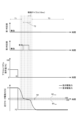
図4は、実施形態のゼロクロス制御の第1例を示すタイムチャートである。第1例のゼロクロス制御は、走行モータ11の駆動力がゼロ駆動力をまたいで変化する際の衝撃が抑制される動作例を示す。図4のタイムチャートにおいて、第1判定部41の有効と無効は、第1条件を満たしたと判定したか否かを示し、第2判定部42の有効と無効は、ゼロクロス条件を満たしたと判定したか否かを示す。
<First Example of Zero Cross Control>
4 is a time chart showing a first example of the zero-cross control of the embodiment. The zero-cross control of the first example shows an operation example in which an impact when the driving force of the traveling motor 11 changes across zero driving force is suppressed. In the time chart of FIG. 4, the enable/disable of the
図4に示すように、アクセルペダル21の操作量が加速の操作量f1から減速の操作量f2に変化すると、この操作に応じて要求駆動力が正の値F1から負の値F2まで変化する。指示駆動力がゼロ近傍範囲W1から離れている期間T1、T3において、レート処理部32では、ゼロクロス処理部40は作用せず、通常レート処理部33が通常値の変化率制御パラメータを用いて指示駆動力を算出する。この期間の変化率の制限の制御により、急激な駆動力の変化が緩和されつつ要求駆動力に追従する指示駆動力が算出される。そして、駆動制御部35による駆動制御により算出された指示駆動力に相当する駆動力が走行モータ11から出力される。期間T3では、負の指示駆動力に対応して走行モータ11が回生駆動され、負の駆動力が走行モータ11から出力される。
As shown in FIG. 4, when the operation amount of the
図4の動作例は、指示駆動力がゼロ近傍範囲W1に差し掛かる際に、第1判定部41により第1条件を満たすと判定されない例である。すなわち、指示駆動力がゼロ近傍範囲W1に差し掛かると、第2判定部がゼロクロス条件を満たす(現制御サイクルの指示駆動力がゼロ近傍範囲W1内にある)と判定し、ゼロクロスレート処理部43が、現制御サイクルの指示駆動力を、変化率制御パラメータとして第2値を用いて算出する。そして、算出された指示駆動力が駆動制御部35に送られ、当該指示駆動力が走行モータ11から出力される。
The operation example in FIG. 4 is an example in which the
このようなゼロクロスレート処理部43による変化率の制限は、ゼロクロス条件を満たす制御サイクルの期間T2(指示駆動力がゼロ近傍範囲W1に入った制御サイクルからゼロ近傍範囲W1を抜ける制御サイクルまでの期間T2)において継続される。そして、この変化率の制限により、駆動力がゼロ近傍範囲W1のときに、駆動力の変化率が衝撃を抑制するレベルに制限され、走行モータ11が力行運転から回生運転へ切り替わる際の衝撃が低減される。
This restriction on the rate of change by the zero cross
<第2例のゼロクロス制御>
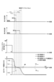
図5は、実施形態のゼロクロス制御の第2例を示すタイムチャートである。図6は、比較例のゼロクロス制御の一例を示すタイムチャートである。図6の比較例は、第1判定部41の判定に基づく制御が行われない駆動力制御装置の動作例である。
<Second Example of Zero Cross Control>
Fig. 5 is a time chart showing a second example of the zero-cross control of the embodiment. Fig. 6 is a time chart showing an example of the zero-cross control of a comparative example. The comparative example of Fig. 6 is an operation example of the driving force control device in which control based on the determination of the
図5と図6に示すように、アクセルペダル21の操作量が加速の操作量f3から減速の操作量f4に変化すると、その操作に応じて要求駆動力が正の値F3から負の値F4まで変化する。指示駆動力がゼロ近傍範囲W1に差し掛かる前の期間T11においては、通常レート処理部33が、通常値である変化率制御パラメータを用いて要求駆動力に追従する指示駆動力を計算する。ここで、例えば、要求駆動力と指示駆動力との差が大きい期間が長いと、変化率の制限が付加されていても、指示駆動力の変化率は大きくなる。さらに、ゼロ近傍範囲W1に差し掛かる直前に算出された指示駆動力が、例えば110Nなど、ゼロ近傍範囲W1に近い場合が生じる。このような場合、通常レート処理部33が、そのまま、次の制御サイクルの指示駆動力を計算した場合、図6の期間T21に示すように、次の指示駆動力はゼロ近傍範囲W1を過ぎてしまう。
As shown in FIG. 5 and FIG. 6, when the operation amount of the
したがって、図6の比較例に示すように、第1判定部41を有さない比較例の構成では、期間T21において、第2判定部42はゼロクロス条件を満たすと判定せず、ゼロ近傍範囲W1で指示駆動力の変化率制御パラメータを第2値に制限する制御の制御漏れが発生してしまう。この場合、走行モータ11が力行運転から回生運転に急激に変化して衝撃が生じる。
Therefore, as shown in the comparative example in FIG. 6, in the comparative example configuration that does not have the
一方、本実施形態の制御では、図5の制御サイクルT12に示すように、現制御サイクルの指示駆動力Fd1をそのときの変化率に従って次の制御サイクルまで変化させた予測駆動力Fd2(図5)が、ゼロ近傍範囲W1を過ぎてしまう場合に、第1判定部41は第1条件を満たすと判定する。そして、この判定結果に基づき、ゼロクロスレート処理部43が、次の制御サイクルの指示駆動力がゼロ近傍範囲W1に留まるように、指示駆動力の変化率を制限する。したがって、次の制御サイクルにおいて、指示駆動力はゼロ近傍範囲W1に含まれ、第2判定部42はゼロクロス条件を満たすと判定する。そして、ゼロクロス条件を外れる制御サイクルまでの期間T13において、ゼロクロスレート処理部43が、変化率制御パラメータを第2値に変更して指示駆動力を算出する。これにより、走行モータ11が力行運転から回生運転へ切り替わる際の衝撃が抑制される。
On the other hand, in the control of this embodiment, as shown in the control cycle T12 of FIG. 5, when the predicted driving force Fd2 (FIG. 5) obtained by changing the indicated driving force Fd1 of the current control cycle according to the change rate at that time until the next control cycle passes the zero vicinity range W1, the
以上のように、本実施形態の車両1及び制御部30によれば、第1判定部41が、現制御サイクルの指示駆動力と次の制御サイクルの予測駆動力との間の範囲と、ゼロ近傍範囲W1とが少なくとも一部重なるか判別する。そして、ゼロクロスレート処理部43が、第1判定部41の判定結果に基づき、例えば、通常の指示駆動力の変化率の制限よりも強い制限が行われるように、指示駆動力の変化率を制限する。このような変化率の制限により、次の制御サイクルの指示駆動力がゼロ近傍範囲W1に留まり、指示駆動力がゼロ駆動力をまたいで変化する際の制御タイミングの検出漏れを低減できる。したがって、走行モータ11の駆動力がゼロ駆動力をまたいで変化する際に適切に衝撃を抑制できる。
As described above, according to the
また、本実施形態の車両1によれば、駆動輪2の動力を発生する動力源が走行モータ11であるため、指示駆動力の算出から、実際に走行モータ11にその指示駆動力が出力されるまでの遅延が小さい。したがって、上述した制御サイクルごとの制御タイミングの検出と、制御タイミングの検出に基づく指示駆動力の変化率制限とにより、走行モータ11が力行運転から回生運転又はその逆に変化する際に、走行モータ11又は動力伝達経路に生じる衝撃を抑制できる。
In addition, according to the
以上、本発明の実施形態について説明した。しかし、本発明は上記実施形態に限られない。例えば、上記実施形態では、第1判定部41が第1条件を満たすと判定した場合に、一旦、ゼロクロスレート処理部43が、次の制御サイクルの指示駆動力がゼロ近傍範囲W1に留まるように変化率を制限する例を示した。しかし、これに限られず、ゼロクロスレート処理部43は、第1判定部41が第1条件を満たすと判定した場合に、次の制御サイクルから指示駆動力の変化率制御パラメータを、衝撃を抑制する第2値に制限して、指示駆動力を算出するようにしてもよい。また、第1判定部41が判定する第1条件として、現制御サイクルの指示駆動力Fd1と次の制御サイクルの予測駆動力Fd2との間の範囲が、ゼロ近傍範囲W1に一部が重なり、かつ、予測駆動力Fd2がゼロ近傍範囲W1を過ぎてしまうという条件である例を示した。しかし、第1条件からは、予測駆動力Fd2がゼロ近傍範囲W1を過ぎてしまうという条件が除外され、第1条件は、指示駆動力Fd1と予測駆動力Fd2との間の範囲がゼロ近傍範囲W1に一部が重なるという条件のみとしてもよい。このような構成としても、上記実施形態と同様に、衝撃を抑制する制御タイミングの検出漏れを低減し、走行モータ11の駆動力がゼロ駆動力をまたいで変化する際に適切に衝撃を抑制することができる。
The above describes an embodiment of the present invention. However, the present invention is not limited to the above embodiment. For example, in the above embodiment, when the
また、上記実施形態では、運転操作部の操作量と要求駆動力との関係、制御サイクルの時間長、衝撃を抑制する変化率制限が行われるゼロ近傍範囲など、具体的な一例を示したが、実施形態で示した細部は、発明の趣旨を逸脱しない範囲で適宜変更可能である。 In addition, in the above embodiment, specific examples are shown, such as the relationship between the amount of operation of the driving operation unit and the required driving force, the time length of the control cycle, and the range near zero in which the rate of change limit that suppresses impact is performed, but the details shown in the embodiment can be changed as appropriate without departing from the spirit of the invention.
1 車両
2 駆動輪
11 走行モータ
12 インバータ
20 運転操作部
21 アクセルペダル
22 ブレーキペダル
30 制御部
31 要求駆動力算出部
32 レート処理部
33 通常レート処理部
34 指示駆動力出力部
35 駆動制御部
40 ゼロクロス処理部
41 第1判定部
42 第2判定部
43 ゼロクロスレート処理部
REFERENCE SIGNS
Claims (6)
運転指令に基づいて変化する指示駆動力を算出する駆動力算出部と、
前記駆動力算出部により算出された前記指示駆動力を前記駆動力として前記動力源から出力させる駆動制御部と、
を備え、
前記駆動力算出部は、
第1制御サイクルにおいて算出された前記指示駆動力を、前記第1制御サイクルにおいて算出された前記指示駆動力の変化率に応じて、前記第1制御サイクルの次の第2制御サイクルまで変化させた予測駆動力が、第1条件を満たすか否かを判定する第1判定部を含み、
前記第1条件は、前記第1制御サイクルにおいて算出された前記指示駆動力と前記予測駆動力との間の範囲と、駆動力がゼロであるゼロ駆動力を含む第1範囲とが少なくとも一部重なるという条件を含み、
前記駆動力算出部は、前記第1判定部が前記第1条件を満たすと判定した場合に、前記第2制御サイクルで算出する前記指示駆動力の変化率を制限することを特徴とする車両用の駆動力制御装置。 A driving force control device for a vehicle that is mounted on a vehicle having driving wheels and a power source that outputs driving force to the driving wheels,
A driving force calculation unit that calculates a command driving force that changes based on a driving command;
a drive control unit that causes the power source to output the indicated drive force calculated by the drive force calculation unit as the drive force;
Equipped with
The driving force calculation unit
a first determination unit that determines whether a predicted driving force obtained by changing the indicated driving force calculated in a first control cycle until a second control cycle following the first control cycle in accordance with a rate of change of the indicated driving force calculated in the first control cycle satisfies a first condition,
the first condition includes a condition that a range between the indicated driving force and the predicted driving force calculated in the first control cycle at least partially overlaps with a first range including a zero driving force, where the driving force is zero;
A driving force control device for a vehicle, characterized in that the driving force calculation unit limits the rate of change of the indicated driving force calculated in the second control cycle when the first judgment unit determines that the first condition is satisfied.
前記駆動力算出部は、
前記第1制御サイクルにおいて前記第2判定部がゼロクロス条件を満たすと判定した場合に、前記第2制御サイクルにおいて算出する前記指示駆動力の変化率を所定値以下に制限する一方、
前記第1制御サイクルにおいて前記第1判定部が前記第1条件を満たすと判定した場合に、前記第2制御サイクルにおいて算出する前記指示駆動力が前記第1範囲内に留まるように前記指示駆動力の変化率を制限することを特徴とする請求項1又は請求項2に記載の車両用の駆動力制御装置。 the driving force calculation unit further includes a second determination unit that determines whether the command driving force satisfies a zero-crossing condition indicating that the command driving force is within the first range,
The driving force calculation unit
When the second determination unit determines that a zero-crossing condition is satisfied in the first control cycle, the change rate of the indicated driving force calculated in the second control cycle is limited to a predetermined value or less.
3. A driving force control device for a vehicle as described in claim 1 or claim 2, characterized in that when the first judgment unit judges that the first condition is satisfied in the first control cycle, a rate of change of the indicated driving force calculated in the second control cycle is limited so that the indicated driving force remains within the first range.
運転指令に基づいて変化する指示駆動力を算出し、算出された前記指示駆動力を前記駆動力として前記動力源から出力させる回路を備え、
前記回路は、第1制御サイクルにおいて算出された前記指示駆動力を、前記第1制御サイクルにおいて算出された前記指示駆動力の変化率に応じて、前記第1制御サイクルの次の第2制御サイクルまで変化させた予測駆動力が、第1条件を満たすか否かを判定し、
前記第1条件は、前記第1制御サイクルにおいて算出された前記指示駆動力と前記予測駆動力との間の範囲と、駆動力がゼロであるゼロ駆動力を含む第1範囲とが少なくとも一部重なるという条件を含み、
前記回路は、前記第1条件を満たすと判定した場合に、前記第2制御サイクルで算出する前記指示駆動力の変化率を制限する車両用の駆動力制御装置。 A driving force control device for a vehicle that is mounted on a vehicle having driving wheels and a power source that outputs driving force to the driving wheels,
a circuit for calculating a command driving force that changes based on a driving command and for causing the power source to output the calculated command driving force as the driving force;
the circuit determines whether a predicted driving force obtained by changing the command driving force calculated in a first control cycle until a second control cycle following the first control cycle in accordance with a rate of change of the command driving force calculated in the first control cycle satisfies a first condition;
the first condition includes a condition that a range between the indicated driving force and the predicted driving force calculated in the first control cycle at least partially overlaps with a first range including a zero driving force, where the driving force is zero;
The driving force control device for a vehicle, wherein the circuit limits a rate of change of the indicated driving force calculated in the second control cycle when it is determined that the first condition is satisfied.
Priority Applications (2)
| Application Number | Priority Date | Filing Date | Title |
|---|---|---|---|
| US17/126,667 US11745600B2 (en) | 2020-02-04 | 2020-12-18 | Driving force controller for vehicle |
| CN202011526722.2A CN113212182B (en) | 2020-02-04 | 2020-12-22 | Driving force control device for vehicle |
Applications Claiming Priority (2)
| Application Number | Priority Date | Filing Date | Title |
|---|---|---|---|
| JP2020016684 | 2020-02-04 | ||
| JP2020016684 | 2020-02-04 |
Publications (2)
| Publication Number | Publication Date |
|---|---|
| JP2021126039A JP2021126039A (en) | 2021-08-30 |
| JP7561584B2 true JP7561584B2 (en) | 2024-10-04 |
Family
ID=77460215
Family Applications (1)
| Application Number | Title | Priority Date | Filing Date |
|---|---|---|---|
| JP2020196775A Active JP7561584B2 (en) | 2020-02-04 | 2020-11-27 | Driving force control device for vehicle |
Country Status (1)
| Country | Link |
|---|---|
| JP (1) | JP7561584B2 (en) |
Families Citing this family (1)
| Publication number | Priority date | Publication date | Assignee | Title |
|---|---|---|---|---|
| CN116279402B (en) * | 2023-03-29 | 2025-07-25 | 重庆长安汽车股份有限公司 | New energy vehicle torque zero crossing control method and system, new energy vehicle and storage medium |
Citations (1)
| Publication number | Priority date | Publication date | Assignee | Title |
|---|---|---|---|---|
| JP2012105461A (en) | 2010-11-10 | 2012-05-31 | Honda Motor Co Ltd | Controller for electric vehicle |
-
2020
- 2020-11-27 JP JP2020196775A patent/JP7561584B2/en active Active
Patent Citations (1)
| Publication number | Priority date | Publication date | Assignee | Title |
|---|---|---|---|---|
| JP2012105461A (en) | 2010-11-10 | 2012-05-31 | Honda Motor Co Ltd | Controller for electric vehicle |
Also Published As
| Publication number | Publication date |
|---|---|
| JP2021126039A (en) | 2021-08-30 |
Similar Documents
| Publication | Publication Date | Title |
|---|---|---|
| KR101570703B1 (en) | Inter-vehicle control apparatus | |
| CN108290575B (en) | Control system with at least one electronic control unit for controlling an internal combustion engine in a hybrid vehicle | |
| CN103587431A (en) | Torque filtering control method for electric automobile | |
| EP2444275B1 (en) | Motor torque control device | |
| CN101959730A (en) | Control apparatus and method for controlling a hybrid vehicle | |
| US20230400094A1 (en) | Control device and control method of electric vehicle | |
| JP2017017810A (en) | Control device for electric vehicle | |
| JP2015080977A (en) | Travel control device of hybrid vehicle | |
| JP2020029148A (en) | Hybrid vehicle control method and hybrid vehicle control device | |
| JP2015182555A (en) | Automobile | |
| US10071651B2 (en) | Torque control apparatus and method for drive motor | |
| JP2015073347A (en) | Electric-vehicular travel control apparatus | |
| JP2020129938A (en) | Control apparatus for electric vehicle | |
| EP2810840A1 (en) | Decelerating factor-estimating device | |
| JP7561584B2 (en) | Driving force control device for vehicle | |
| JP7588950B2 (en) | Vehicle control device | |
| CN113212182B (en) | Driving force control device for vehicle | |
| KR101738818B1 (en) | Method for controlling the engine of a hybrid vehicle | |
| KR101886443B1 (en) | Method for controlling coast driving at reduced driving speed and Storage medium thereof | |
| JP7200763B2 (en) | electric vehicle | |
| JP2015100225A (en) | Car speed limit device | |
| US12240461B2 (en) | Driving support apparatus | |
| JP2016054631A (en) | Control apparatus of electric vehicle | |
| JP2013135483A (en) | Vehicle braking force control device | |
| JP6044176B2 (en) | Vehicle power generation control device |
Legal Events
| Date | Code | Title | Description |
|---|---|---|---|
| A621 | Written request for application examination |
Free format text: JAPANESE INTERMEDIATE CODE: A621 Effective date: 20231002 |
|
| A131 | Notification of reasons for refusal |
Free format text: JAPANESE INTERMEDIATE CODE: A131 Effective date: 20240319 |
|
| A977 | Report on retrieval |
Free format text: JAPANESE INTERMEDIATE CODE: A971007 Effective date: 20240321 |
|
| A521 | Request for written amendment filed |
Free format text: JAPANESE INTERMEDIATE CODE: A523 Effective date: 20240516 |
|
| TRDD | Decision of grant or rejection written | ||
| A01 | Written decision to grant a patent or to grant a registration (utility model) |
Free format text: JAPANESE INTERMEDIATE CODE: A01 Effective date: 20240827 |
|
| A61 | First payment of annual fees (during grant procedure) |
Free format text: JAPANESE INTERMEDIATE CODE: A61 Effective date: 20240924 |
|
| R150 | Certificate of patent or registration of utility model |
Ref document number: 7561584 Country of ref document: JP Free format text: JAPANESE INTERMEDIATE CODE: R150 |