JP7561571B2 - Intercom Equipment - Google Patents
Intercom Equipment Download PDFInfo
- Publication number
- JP7561571B2 JP7561571B2 JP2020179069A JP2020179069A JP7561571B2 JP 7561571 B2 JP7561571 B2 JP 7561571B2 JP 2020179069 A JP2020179069 A JP 2020179069A JP 2020179069 A JP2020179069 A JP 2020179069A JP 7561571 B2 JP7561571 B2 JP 7561571B2
- Authority
- JP
- Japan
- Prior art keywords
- piece
- positioning
- positioning rib
- button
- rib
- Prior art date
- Legal status (The legal status is an assumption and is not a legal conclusion. Google has not performed a legal analysis and makes no representation as to the accuracy of the status listed.)
- Active
Links
Images


Landscapes
- Telephone Set Structure (AREA)
Description
本発明は、たとえばインターホン親機等の押し込み操作可能な操作ボタンを備えたインターホン機器に関するものである。 The present invention relates to an intercom device that has an operation button that can be operated by pressing, such as an intercom master unit.
従来、インターホン親機等の一般的なインターホン機器には、押し込み操作可能な操作ボタンが設置されている。そして、そのようなインターホン機器の一つとして、本体ケースの前面に押し込み操作可能な操作ボタンが左右方向へ複数並設されたものも考案されている(たとえば特許文献1)。 Conventionally, common intercom devices such as intercom master units are equipped with a push-button that can be operated by pressing it. One such intercom device has been devised in which multiple push-buttons are arranged side-by-side in the left-right direction on the front of the main body case (for example, see Patent Document 1).
上述したような操作ボタンは、一旦ケース側に仮組みした後、たとえば前ケースと後ケースとを組み付けたり、前ケースの前面にパネル部材を組み付けたりすることで本体ケースに設置されることが多い。しかしながら、仮組みした状態において操作ボタンの位置がずれやすいという問題がある。特に複数の操作ボタンが所定方向へ並設されているようなインターホン機器では、そのような位置ずれに係る問題が顕著であり、製造作業の煩雑化を招く要因となっていた。 Operation buttons such as those described above are often installed on the main case by first temporarily assembling them on the case side, and then, for example, assembling the front and rear cases together, or assembling a panel member on the front surface of the front case. However, there is a problem in that the operation buttons are prone to misalignment in the temporarily assembled state. This problem is particularly noticeable in intercom devices in which multiple operation buttons are arranged side by side in a specific direction, and is a factor that leads to complication of the manufacturing process.
そこで、本発明は、上記問題に鑑みなされたものであって、仮組み状態にある操作ボタンが位置ずれせず、製造作業を簡易化することができるインターホン機器を提供しようとするものである。 Therefore, the present invention has been made in consideration of the above problems, and aims to provide an intercom device in which the operating buttons in the provisionally assembled state do not shift out of position, simplifying the manufacturing process.
上記目的を達成するために、本発明のうち請求項1に記載の発明は、本体ケースの前面に、押し込み操作可能な操作ボタンが左右方向へ複数並設されてなるインターホン機器であって、本体ケースに、上方へ突出する上片、下方へ突出する下片、左方へ突出する左片、及び右方へ突出する右片を有する正面視十字状の位置決めリブが前方へ突設されているとともに、位置決めリブが、左右方向へ所定の間隔毎に複数設けられている一方、操作ボタンの左部に、右片を上下から挟み込み可能な第1の位置決め凸部が後方へ突設されているとともに、操作ボタンの右部に、左片を上下から挟み込み可能な第2の位置決め凸部が後方へ突設されており、操作ボタンが、左右に隣り合う2つの位置決めリブ間において、第1の位置決め凸部により左側の位置決めリブの右片を挟み込み、且つ、第2の位置決め凸部により右側の位置決めリブの左片を挟み込んだ状態で設置されていることを特徴とする。
請求項1に記載の発明によれば、操作ボタンを、左右に隣り合う2つの位置決めリブ間において、第1の位置決め凸部により左側の位置決めリブの右片を挟み込み、且つ、第2の位置決め凸部により右側の位置決めリブの左片を挟み込んだ状態で設置可能となっている。したがって、たとえば仮組み状態等において操作ボタンが上下方向にも左右方向にも位置ずれしないため、製造作業(特に複数の操作ボタンを左右に並設する作業)の簡易化を図ることができる。また、左右で隣り合う2つの操作ボタンで1つの位置決めリブを共用可能であるため、構造の簡素化、ひいてはインターホン機器の小型化を図ることができる。
In order to achieve the above-mentioned object, the invention described in claim 1 of the present invention is an intercom device having a plurality of operation buttons that can be operated by pressing them arranged in the left-right direction on the front surface of a main body case, wherein a cross-shaped positioning rib when viewed from the front protrudes forward from the main body case, the positioning rib having an upper piece protruding upward, a lower piece protruding downward, a left piece protruding to the left, and a right piece protruding to the right, and wherein a plurality of positioning ribs are provided at predetermined intervals in the left-right direction, while a first positioning convex portion protrudes backward from the left portion of the operation button, capable of clamping the right piece from above and below, and a second positioning convex portion protrudes backward from the right portion of the operation button, capable of clamping the left piece from above and below, and wherein the operation button is installed between two adjacent positioning ribs, with the right piece of the left positioning rib clamped by the first positioning convex portion, and the left piece of the right positioning rib clamped by the second positioning convex portion.
According to the invention described in claim 1, the operation button can be installed between two adjacent positioning ribs in a state in which the right piece of the left positioning rib is sandwiched by the first positioning protrusion and the left piece of the right positioning rib is sandwiched by the second positioning protrusion. Therefore, for example, in a temporary assembly state, the operation button does not shift in position in the vertical or horizontal directions, so that the manufacturing work (particularly the work of arranging multiple operation buttons side by side) can be simplified. In addition, one positioning rib can be shared by two adjacent operation buttons on the left and right, so that the structure can be simplified and the intercom device can be made smaller.
また、上記目的を達成するために、本発明のうち請求項2に記載の発明は、本体ケースの前面に、押し込み操作可能な操作ボタンが上下方向へ複数並設されてなるインターホン機器であって、本体ケースに、上方へ突出する上片、下方へ突出する下片、左方へ突出する左片、及び右方へ突出する右片を有する正面視十字状の位置決めリブが前方へ突設されているとともに、位置決めリブが、上下方向へ所定の間隔毎に複数設けられている一方、操作ボタンの上部に、下片を左右から挟み込み可能な第1の位置決め凸部が後方へ突設されているとともに、操作ボタンの下部に、上片を左右から挟み込み可能な第2の位置決め凸部が後方へ突設されており、操作ボタンが、上下に隣り合う2つの位置決めリブ間において、第1の位置決め凸部により上側の位置決めリブの下片を挟み込み、且つ、第2の位置決め凸部により下側の位置決めリブの上片を挟み込んだ状態で設置されていることを特徴とする。
請求項2に記載の発明によれば、操作ボタンを、上下に隣り合う2つの位置決めリブ間において、第1の位置決め凸部により上側の位置決めリブの下片を挟み込み、且つ、第2の位置決め凸部により下側の位置決めリブの上片を挟み込んだ状態で設置可能となっている。したがって、たとえば仮組み状態等において操作ボタンが上下方向にも左右方向にも位置ずれしないため、製造作業(特に複数の操作ボタンを上下に並設する作業)の簡易化を図ることができる。また、上下で隣り合う2つの操作ボタンで1つの位置決めリブを共用可能であるため、構造の簡素化、ひいてはインターホン機器の小型化を図ることができる。
In addition, in order to achieve the above-mentioned object, the invention described in
According to the invention described in
本発明によれば、本体ケースに、上方へ突出する上片、下方へ突出する下片、左方へ突出する左片、及び右方へ突出する右片を有する正面視十字状の位置決めリブを前方へ突設するとともに、該位置決めリブを、左右方向(請求項2では上下方向)へ所定の間隔毎に複数設ける一方、操作ボタンの左部(請求項2では上部)に、右片を上下から(請求項2では下片を左右から)挟み込み可能な第1の位置決め凸部が後方へ突設されているとともに、操作ボタンの右部(請求項2では下部)に、左片を上下から(請求項2では上片を左右から)挟み込み可能な第2の位置決め凸部が後方へ突設されており、操作ボタンを、左右(請求項2では上下)に隣り合う2つの位置決めリブ間において、第1の位置決め凸部により左側の位置決めリブの右片(請求項2では上側の位置決めリブの下片)を挟み込み、且つ、第2の位置決め凸部により右側の位置決めリブの左片(請求項2では下側の位置決めリブの上片)を挟み込んだ状態で設置するようになっている。したがって、たとえば仮組み状態等において操作ボタンが上下方向にも左右方向にも位置ずれしないため、製造作業(特に複数の操作ボタンを左右(請求項2では上下)に並設する作業)の簡易化を図ることができる。 According to the present invention, a positioning rib that is cross-shaped when viewed from the front and has an upper piece that protrudes upward, a lower piece that protrudes downward, a left piece that protrudes left, and a right piece that protrudes right is provided on the main body case, protruding forward, and a plurality of such positioning ribs are provided at predetermined intervals in the left-right direction (up-down direction in claim 2), while a first positioning protrusion that can clamp the right piece from above and below (the lower piece from left and right in claim 2) is provided on the left part of the operation button (upper part in claim 2) protruding backward, and a second positioning protrusion that can clamp the right piece from above and below (the lower piece from left and right in claim 2) is provided on the right part of the operation button (upper part in claim 2). A second positioning protrusion that can clamp the left piece from above and below (the upper piece from left and right in claim 2) protrudes rearward from the left side of the button, and the button is set between two adjacent positioning ribs (top and bottom in claim 2) with the right piece of the left positioning rib (the lower piece of the upper positioning rib in claim 2) clamped by the first positioning protrusion, and the left piece of the right positioning rib (the upper piece of the lower positioning rib in claim 2) clamped by the second positioning protrusion. Therefore, for example, in a temporary assembly state, the button does not shift in position in the vertical or horizontal directions, which simplifies the manufacturing process (particularly the process of arranging multiple buttons side by side (top and bottom in claim 2)).
以下、本発明の一実施形態となるインターホン親機について、図面にもとづき詳細に説明する。 Below, we will explain in detail the intercom master unit, which is one embodiment of the present invention, with reference to the drawings.
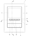
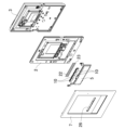
図1は、インターホン親機1の前面側を示した説明図である。図2は、分解状態にあるインターホン親機1を示した斜視説明図である。図3は、設定ボタン10の斜視説明図であり、(a)は前側から、(b)は後側から夫々示している。図4(a)は、前ケース2における設定ボタン10、10・・の設置部分を前側から示した説明図であり、(b)は同部分を示した斜視説明図である。図5は、図1中のA-A線における設定ボタン10部分を示した断面説明図である。図6は、図1中のB-B線における設定ボタン10、10部分を示した断面説明図である。
Figure 1 is an explanatory diagram showing the front side of the intercom master unit 1. Figure 2 is an explanatory perspective view showing the intercom master unit 1 in a disassembled state. Figure 3 is an explanatory perspective view of the
インターホン親機1は、前側に配置される前ケース2、前ケース2の後側に組み付けられる後ケース3、及び前ケース2の前面に組み付けられるパネル部材7で構成される本体ケースを有してなるもので、本体ケースの前面には、インターホン子機(図示せず)で撮像された映像等を表示する表示部4が設けられている。また、本体ケースの前面で表示部4の右側には、インターホン子機との間で通話するためのマイク部6が設けられている。さらに、本体ケースの前面で表示部4の下側には、インターホン子機からの呼び出しに対して応答する際に操作する応答ボタン5が設けられているとともに、自身の設定等のための4つの設定ボタン10、10・・が左右方向に並設されている。そして、このようなインターホン親機1は、居室内の壁面等に設置されており、インターホン子機からの呼び出しに応じて表示部4に映像を表示するとともに、応答ボタン5が操作されたことをもって、インターホン子機との間での通話を可能な状態とする。なお、インターホン子機との間で通話するためのスピーカ部は、本体ケースの後面側に設けられている。また、8は透明板であって、パネル部材7を構成する要素の1つである。
The intercom master unit 1 has a main body case composed of a
ここで、本発明の要部となる4つの設定ボタン10、10・・の設置構造について説明する。
各設定ボタン10は、ユーザーが押し込み操作するための操作部11と、操作部11の上部から後方へ延びるとともに上方へ折り曲げられた上当接片12と、操作部11の下部から後方へ延びるとともに下方へ折り曲げられた下当接片13と、操作部11の中央から後方へ突出する操作突起14とを有している。また、上当接片12の左右両端には、上当接片12の後面から更に後方へ突出する上位置決め突起15、15が設けられている。一方、下当接片13の左右両端にも、下当接片13の後面から更に後方へ突出する下位置決め突起16、16が設けられている。そして、上位置決め突起15、15と下位置決め突起16、16とは、上下方向に所定の間隔を隔てて対向している。
Here, the installation structure of the four
Each
一方、前ケース2側における4つの設定ボタン10、10・・の設置箇所には、各設定ボタン10によりON/OFF操作されるスイッチ30(図6に示す)を露出させるための4つの操作窓21、21・・が左右方向へ所定の間隔毎に設けられている。また、前ケース2の前面で、操作窓21、21・・の上隣には左右方向へ長い柱状の上弾性部材22が取り付けられている一方、操作窓21、21・・の下隣にも左右方向へ長い柱状の下弾性部材23が取り付けられている。さらに、前ケース2の前面で、左右方向で隣り合う操作窓21と操作窓21との間となる箇所には、前方へ突出する第1の位置決めリブ24が設けられている。また、左右両端に位置する操作窓21、21の左右方向で更に外側には、前方へ突出する第2の位置決めリブ25が設けられている。
On the other hand, at the installation positions of the four
位置決めリブ24は、正面視十字状に形成されており、上方へ突出する上片24a、右方へ突出する右片24b、下方へ突出する下片24c、及び左方へ突出する左片24dを有している。そして、右片24b及び左片24dの厚み(上下幅)は、各設定ボタン10における上下の両位置決め突起15、16間の隙間よりも薄くなっている。また、位置決めリブ24、24同士の左右方向での間隔は、設定ボタン10の左右幅と略同じとなっている。
The
一方、位置決めリブ25は、上方へ突出する上片25a、及び下方へ突出する下片25cを有するとともに、左右方向へ突出する側片としては、夫々左右内方へ突出する側片25bのみを有している。そして、側片25bの厚み(上下幅)は、位置決めリブ24の右片24b及び左片24dの厚みと同じとなっている。また、位置決めリブ25と左右方向で隣となる位置決めリブ24との左右方向での間隔も、設定ボタン10の左右幅と略同じとなっている。
The
そして、設定ボタン10を前ケース2に設置するにあたっては、各設定ボタン10の左側にある上下両位置決め突起15、16が左側に位置する位置決めリブ24の右片24b(若しくは左端に位置する位置決めリブ25の側片25b)を上下から挟みこみ、且つ、各設定ボタン10の右側にある上下両位置決め突起15、16が右側に位置する位置決めリブ24の左片24d(若しくは右端に位置する位置決めリブ25の側片25b)を上下から挟み込むように設定ボタン10を配置し、設定ボタン10を仮組みすればよい。このように設定ボタン10を配置することで、設定ボタン10の上下方向での位置決めがなされることになる(すなわち、位置決めリブ24の右片24bや左片24d、位置決めリブ25の側片25bは、設定ボタン10の上下方向での位置決めに機能する)。また、そのように配置された設定ボタン10における上下両位置決め突起15、16の左右夫々外側の面と、位置決めリブ24の上片24a及び下片24c(若しくは位置決めリブ25の上片25a及び下片25c)とが干渉することで、設定ボタン10の左右方向での位置決めがなされるようになっている(すなわち、位置決めリブ24の上片24aや下片24cと、位置決めリブ25の上片25aや下片25cとは、設定ボタン10の左右方向での位置決めに機能する)。なお、上述したように設定ボタン10を配置することで、設定ボタン10の操作突起14が、操作窓21内に露出するスイッチ30の前方に位置する。
When installing the
さらに、設定ボタン10、10・・を前ケース2の前面側に配置して仮組みした後には、パネル部材7に開設されているボタン窓26内に設定ボタン10、10・・の操作部11、11・・を位置させつつ、パネル部材7を前ケース2の前面に組み付ける。すると、上当接片12がはパネル部材7の後面(ボタン窓26の開口縁の上側部分)と上弾性部材22の表面とにより、下当接片13がパネル部材7の後面(ボタン窓26の開口縁の下側部分)と下弾性部材23の表面とにより夫々前後から挟持され、設定ボタン10、10・・の設置は完了となる。なお、ボタン窓26の左右幅は、4つの設定ボタン10、10・・の左右幅と略同じとされている、また、ボタン窓26の上下幅は、各設定ボタン10の操作部11の上下幅と略同じとされている。
After the
以上のような構成を有するインターホン親機1によれば、前ケース2に複数の操作窓21、21・・を左右方向へ所定の間隔毎に開設するとともに、操作窓21と操作窓21との間となる位置に、上方へ突出する上片24a、下方へ突出する下片24c、左方へ突出する左片24d、及び右方へ突出する右片24bを有する正面視十字状の位置決めリブ24を前方へ突設している。また、左右両端の操作窓21、21の左右方向で更に外側に、上方へ突出する上片25a、下方へ突出する下片25c、及び左右方向で内側となる側方へ突出する側片25bを有する位置決めリブ25を前方へ突設している。一方、設定ボタン10の左右両部に、後方へ突出する上案内突起15及び下案内突起16を夫々設けている。そして、各設定ボタン10の左側にある上下両位置決め突起15、16が左側に位置する位置決めリブ24の右片24b(若しくは左端に位置する位置決めリブ25の側片25b)を上下から挟みこみ、且つ、各設定ボタン10の右側にある上下両位置決め突起15、16が右側に位置する位置決めリブ24の左片24d(若しくは右端に位置する位置決めリブ25の側片25b)を上下から挟み込んだ状態で、設定ボタン10、10・・が設置されるようにした。したがって、位置決めリブ24、25を利用して設定ボタン10、10・・を配置し、設定ボタン10、10・・を仮組した際、位置決めリブ24の右片24b及び左片24dや位置決めリブ25の側片25bが上下方向での位置決めに機能するとともに、位置決めリブ24、25の上片24a、25a及び下片24c、25cが左右方向での位置決めに機能して設定ボタン10、10・・が位置ずれしないため、製造作業(特に複数の設定ボタン10、10・・を左右に並設する作業)の簡易化を図ることができる。
According to the intercom master unit 1 having the above-mentioned configuration, a plurality of
また、位置決めリブ24については、右片24bは自身の右側に位置する設定ボタン10の位置決めとして、左片24dは自身の左側に位置する設定ボタン10の位置決めとして、上片24a及び下片24cは自身の左右両側に位置する設定ボタン10、10の位置決めとして機能することになる。すなわち、左右で隣り合う2つの設定ボタン10、10で1つの位置決めリブ24を共用する構成となっているため、構造の簡素化、ひいてはインターホン親機1の小型化を図ることができる。
As for the
なお、本発明に係るインターホン機器は、インターホン機器の全体的な構成は勿論、操作ボタンの設置構造に係る構成等についても、本発明の趣旨を逸脱しない範囲で必要に応じて適宜変更することができる。 The intercom device according to the present invention can be modified as necessary without departing from the spirit of the present invention, not only in terms of the overall configuration of the intercom device, but also in terms of the configuration related to the installation structure of the operation buttons, etc.
たとえば、上記実施形態では、前ケースの前面側に操作ボタンを配置しているため、前ケースの前面に前方へ突出する位置決めリブを設けているが、本体ケース内に操作ボタンを配置するようなインターホン機器についても本発明は好適に採用することができ、そのような場合には、たとえば後ケースに前方へ突出する位置決めリブを設ける等すればよく、位置決めリブをどこに設けるかについては適宜設計変更可能である。 For example, in the above embodiment, the operation button is located on the front side of the front case, so a positioning rib that protrudes forward is provided on the front of the front case, but the present invention can also be suitably used in intercom devices in which the operation button is located inside the main case. In such cases, for example, a positioning rib that protrudes forward can be provided on the rear case, and the location of the positioning rib can be appropriately modified in the design.
また、上記実施形態では複数の操作ボタンを左右方向へ並設するとしているが、操作ボタンを上下方向へ並設するとしてもよく、そのような場合には、操作ボタンの左右ではなく、上下両部に位置決め凸部を設ければよい。
さらに、上記実施形態では全ての操作ボタンを設定ボタンとしているが、操作ボタンを応答ボタン及び設定ボタンとする等、複数種類のボタンとしても何ら問題はない。
加えて、上記実施形態ではインターホン親機について説明しているが、本発明は、押し込み操作可能な操作ボタンを備えてさえいれば、インターホン子機等の他のインターホン機器に対しても好適に採用することができる。
In addition, although in the above embodiment, multiple operation buttons are arranged side by side in the left-right direction, the operation buttons may also be arranged side by side in the up-down direction. In such a case, positioning protrusions can be provided on both the top and bottom of the operation button, rather than on the left and right.
Furthermore, in the above embodiment, all the operation buttons are setting buttons, but there is no problem if the operation buttons are multiple types of buttons, such as response buttons and setting buttons.
In addition, while the above embodiment describes an intercom master unit, the present invention can also be suitably adopted for other intercom devices, such as intercom slave units, as long as they are equipped with an operation button that can be operated by pressing.
1・・インターホン親機(インターホン機器)、2・・前ケース(本体ケース)、3・・後ケース(本体ケース)、7・・パネル部材(本体ケース)、10・・設定ボタン(操作ボタン)、15・・上案内突起(位置決め凸部)、16・・下案内突起(位置決め凸部)、24・・位置決めリブ、24a・・上片、24b・・右片、24c・・下片、24d・・左片、25・・位置決めリブ、25a・・上片、25b・・側片、25c・・下片。 1: Intercom master unit (intercom device), 2: Front case (main body case), 3: Rear case (main body case), 7: Panel member (main body case), 10: Setting button (operation button), 15: Upper guide protrusion (positioning protrusion), 16: Lower guide protrusion (positioning protrusion), 24: Positioning rib, 24a: Upper piece, 24b: Right piece, 24c: Lower piece, 24d: Left piece, 25: Positioning rib, 25a: Upper piece, 25b: Side piece, 25c: Lower piece.
Claims (2)
前記本体ケースに、上方へ突出する上片、下方へ突出する下片、左方へ突出する左片、及び右方へ突出する右片を有する正面視十字状の位置決めリブが前方へ突設されているとともに、前記位置決めリブが、左右方向へ所定の間隔毎に複数設けられている一方、
前記操作ボタンの左部に、前記右片を上下から挟み込み可能な第1の位置決め凸部が後方へ突設されているとともに、前記操作ボタンの右部に、前記左片を上下から挟み込み可能な第2の位置決め凸部が後方へ突設されており、
前記操作ボタンが、左右に隣り合う2つの前記位置決めリブ間において、前記第1の位置決め凸部により左側の前記位置決めリブの前記右片を挟み込み、且つ、前記第2の位置決め凸部により右側の前記位置決めリブの前記左片を挟み込んだ状態で設置されていることを特徴とするインターホン機器。 An intercom device having a plurality of push-buttons arranged in a row in the left-right direction on the front surface of a main body case,
The main body case is provided with a positioning rib protruding forward, the positioning rib having a cross shape as seen from the front and having an upper piece protruding upward, a lower piece protruding downward, a left piece protruding leftward, and a right piece protruding rightward, the positioning rib being provided in a plurality at predetermined intervals in the left-right direction;
a first positioning protrusion capable of sandwiching the right piece from above and below is provided on a left portion of the operation button so as to protrude rearward, and a second positioning protrusion capable of sandwiching the left piece from above and below is provided on a right portion of the operation button so as to protrude rearward,
An intercom device characterized in that the operation button is installed between two adjacent positioning ribs, with the first positioning protrusion clamping the right piece of the left-side positioning rib and the second positioning protrusion clamping the left piece of the right-side positioning rib.
前記本体ケースに、上方へ突出する上片、下方へ突出する下片、左方へ突出する左片、及び右方へ突出する右片を有する正面視十字状の位置決めリブが前方へ突設されているとともに、前記位置決めリブが、上下方向へ所定の間隔毎に複数設けられている一方、
前記操作ボタンの上部に、前記下片を左右から挟み込み可能な第1の位置決め凸部が後方へ突設されているとともに、前記操作ボタンの下部に、前記上片を左右から挟み込み可能な第2の位置決め凸部が後方へ突設されており、
前記操作ボタンが、上下に隣り合う2つの前記位置決めリブ間において、前記第1の位置決め凸部により上側の前記位置決めリブの前記下片を挟み込み、且つ、前記第2の位置決め凸部により下側の前記位置決めリブの前記上片を挟み込んだ状態で設置されていることを特徴とするインターホン機器。 An intercom device having a plurality of push-buttons arranged vertically on the front surface of a main body case,
The main body case is provided with a positioning rib protruding forward, the positioning rib having a cross shape as seen from the front and having an upper piece protruding upward, a lower piece protruding downward, a left piece protruding leftward, and a right piece protruding rightward, the positioning rib being provided in a plurality at predetermined intervals in the up-down direction;
a first positioning protrusion capable of sandwiching the lower piece from the left and right is provided on an upper portion of the operation button so as to protrude rearward, and a second positioning protrusion capable of sandwiching the upper piece from the left and right is provided on a lower portion of the operation button so as to protrude rearward,
An intercom device characterized in that the operation button is installed between two adjacent positioning ribs, with the first positioning protrusion clamping the lower piece of the upper positioning rib and the second positioning protrusion clamping the upper piece of the lower positioning rib.
Priority Applications (1)
| Application Number | Priority Date | Filing Date | Title |
|---|---|---|---|
| JP2020179069A JP7561571B2 (en) | 2020-10-26 | 2020-10-26 | Intercom Equipment |
Applications Claiming Priority (1)
| Application Number | Priority Date | Filing Date | Title |
|---|---|---|---|
| JP2020179069A JP7561571B2 (en) | 2020-10-26 | 2020-10-26 | Intercom Equipment |
Publications (2)
| Publication Number | Publication Date |
|---|---|
| JP2022070053A JP2022070053A (en) | 2022-05-12 |
| JP7561571B2 true JP7561571B2 (en) | 2024-10-04 |
Family
ID=81534382
Family Applications (1)
| Application Number | Title | Priority Date | Filing Date |
|---|---|---|---|
| JP2020179069A Active JP7561571B2 (en) | 2020-10-26 | 2020-10-26 | Intercom Equipment |
Country Status (1)
| Country | Link |
|---|---|
| JP (1) | JP7561571B2 (en) |
Citations (3)
| Publication number | Priority date | Publication date | Assignee | Title |
|---|---|---|---|---|
| JP2006120378A (en) | 2004-10-20 | 2006-05-11 | Funai Electric Co Ltd | Electronic apparatus |
| JP2008198521A (en) | 2007-02-14 | 2008-08-28 | Denso Corp | In-car operating device |
| JP2016100202A (en) | 2014-11-21 | 2016-05-30 | クラリオン株式会社 | Button guide structure |
-
2020
- 2020-10-26 JP JP2020179069A patent/JP7561571B2/en active Active
Patent Citations (3)
| Publication number | Priority date | Publication date | Assignee | Title |
|---|---|---|---|---|
| JP2006120378A (en) | 2004-10-20 | 2006-05-11 | Funai Electric Co Ltd | Electronic apparatus |
| JP2008198521A (en) | 2007-02-14 | 2008-08-28 | Denso Corp | In-car operating device |
| JP2016100202A (en) | 2014-11-21 | 2016-05-30 | クラリオン株式会社 | Button guide structure |
Also Published As
| Publication number | Publication date |
|---|---|
| JP2022070053A (en) | 2022-05-12 |
Similar Documents
| Publication | Publication Date | Title |
|---|---|---|
| US11895784B2 (en) | Electronic control apparatus | |
| JP7561571B2 (en) | Intercom Equipment | |
| JPWO2010004631A1 (en) | Elevator operation panel device | |
| JP5572595B2 (en) | Push button device for telephone equipment | |
| JP2017060005A (en) | Intercom equipment | |
| JP7558746B2 (en) | Intercom Equipment | |
| JP7445478B2 (en) | intercom equipment | |
| US8760590B2 (en) | Attachment structure for control key unit | |
| JP7566593B2 (en) | Intercom Equipment | |
| KR200234990Y1 (en) | Structure of push button for elevator | |
| JP7595472B2 (en) | Intercom Equipment | |
| JP2006120378A (en) | Electronic apparatus | |
| JP7465707B2 (en) | Button operation device | |
| JP2024104194A (en) | Button structure and intercom apparatus | |
| JP6174324B2 (en) | Input device for portable electronic device and portable electronic device | |
| KR100863311B1 (en) | Control panel assembly | |
| CN217719399U (en) | Mechanical key, controller and household electrical appliance | |
| JP2014182973A (en) | Operation input device | |
| JP6491987B2 (en) | Intercom equipment | |
| JP5048549B2 (en) | Electronics | |
| JP4132248B2 (en) | Display switch | |
| JP2021141504A (en) | Intercom device | |
| JP2024104195A (en) | Intercom Equipment | |
| JP3488731B2 (en) | Hands-free calling TV intercom | |
| JP2017228552A (en) | Panel panel assembly structure |
Legal Events
| Date | Code | Title | Description |
|---|---|---|---|
| A621 | Written request for application examination |
Free format text: JAPANESE INTERMEDIATE CODE: A621 Effective date: 20230817 |
|
| A977 | Report on retrieval |
Free format text: JAPANESE INTERMEDIATE CODE: A971007 Effective date: 20240628 |
|
| A131 | Notification of reasons for refusal |
Free format text: JAPANESE INTERMEDIATE CODE: A131 Effective date: 20240702 |
|
| TRDD | Decision of grant or rejection written | ||
| A01 | Written decision to grant a patent or to grant a registration (utility model) |
Free format text: JAPANESE INTERMEDIATE CODE: A01 Effective date: 20240827 |
|
| A61 | First payment of annual fees (during grant procedure) |
Free format text: JAPANESE INTERMEDIATE CODE: A61 Effective date: 20240924 |
|
| R150 | Certificate of patent or registration of utility model |
Ref document number: 7561571 Country of ref document: JP Free format text: JAPANESE INTERMEDIATE CODE: R150 |