JP7561561B2 - Anti-adhesion agent spraying device - Google Patents
Anti-adhesion agent spraying device Download PDFInfo
- Publication number
- JP7561561B2 JP7561561B2 JP2020164010A JP2020164010A JP7561561B2 JP 7561561 B2 JP7561561 B2 JP 7561561B2 JP 2020164010 A JP2020164010 A JP 2020164010A JP 2020164010 A JP2020164010 A JP 2020164010A JP 7561561 B2 JP7561561 B2 JP 7561561B2
- Authority
- JP
- Japan
- Prior art keywords
- transport vehicle
- adhesion agent
- loading platform
- swivel arm
- spraying
- Prior art date
- Legal status (The legal status is an assumption and is not a legal conclusion. Google has not performed a legal analysis and makes no representation as to the accuracy of the status listed.)
- Active
Links
- 238000005507 spraying Methods 0.000 title claims description 49
- 239000003795 chemical substances by application Substances 0.000 claims description 84
- 239000007921 spray Substances 0.000 claims description 76
- 239000010426 asphalt Substances 0.000 claims description 47
- 239000000203 mixture Substances 0.000 claims description 37
- 238000001514 detection method Methods 0.000 claims description 6
- 239000003981 vehicle Substances 0.000 description 92
- 230000032258 transport Effects 0.000 description 87
- 230000002265 prevention Effects 0.000 description 18
- 239000003112 inhibitor Substances 0.000 description 11
- 238000010586 diagram Methods 0.000 description 4
- 238000003860 storage Methods 0.000 description 4
- 230000000694 effects Effects 0.000 description 3
- 239000003921 oil Substances 0.000 description 3
- 235000019198 oils Nutrition 0.000 description 3
- 239000002699 waste material Substances 0.000 description 3
- 239000000295 fuel oil Substances 0.000 description 2
- 235000015112 vegetable and seed oil Nutrition 0.000 description 2
- 239000008158 vegetable oil Substances 0.000 description 2
- XLYOFNOQVPJJNP-UHFFFAOYSA-N water Substances O XLYOFNOQVPJJNP-UHFFFAOYSA-N 0.000 description 2
- 230000009194 climbing Effects 0.000 description 1
- 238000011109 contamination Methods 0.000 description 1
- 239000003925 fat Substances 0.000 description 1
- 238000007710 freezing Methods 0.000 description 1
- 230000008014 freezing Effects 0.000 description 1
- 239000007788 liquid Substances 0.000 description 1
- 239000002075 main ingredient Substances 0.000 description 1
- 238000004519 manufacturing process Methods 0.000 description 1
- 238000000034 method Methods 0.000 description 1
- 238000007711 solidification Methods 0.000 description 1
- 230000008023 solidification Effects 0.000 description 1
- 239000004094 surface-active agent Substances 0.000 description 1
- 238000011144 upstream manufacturing Methods 0.000 description 1
- 235000019871 vegetable fat Nutrition 0.000 description 1
Images


Landscapes
- Road Paving Machines (AREA)
Description
本発明は、アスファルト合材の付着を抑制する付着防止剤の噴霧装置に関し、特にアスファルト合材の搬送車両の荷台に対して付着防止剤を噴霧する噴霧装置に関する。 The present invention relates to a spraying device for an anti-adhesion agent that suppresses adhesion of asphalt mixtures, and in particular to a spraying device that sprays an anti-adhesion agent onto the loading platform of a vehicle transporting asphalt mixtures.
従来、アスファルト合材製造工場に設置されるアスファルトプラントでは、製造したアスファルト合材をダンプトラック等の搬送車両の荷台に払い出して出荷する際、粘着性を有するアスファルト合材が前記荷台表面に付着するのを抑制すべく、例えば、運転手がその都度荷台に上がり、適宜の容器に入れた重油や軽油、或いは植物性油脂等を主成分とする各種の付着防止剤を手作業にて荷台表面に散布している。 Conventionally, in asphalt plants installed in asphalt mixture manufacturing factories, when the manufactured asphalt mixture is unloaded onto the loading platform of a transport vehicle such as a dump truck for shipping, in order to prevent the sticky asphalt mixture from adhering to the surface of the loading platform, for example, the driver climbs onto the loading platform each time and manually sprays various types of adhesion prevention agents, the main ingredients of which are heavy oil, light oil, or vegetable oil, etc., in suitable containers, onto the surface of the loading platform.
ところで、前記搬送車両の荷台は油系の付着防止剤の散布に伴って滑り易い状態にあり、このような荷台に運転手が上がって行う前記作業は転倒や転落等の事故を招く危険性があって安全上好ましいものではなく、また甚だ面倒で運転手に多大な負担を強いるものとなっている。また、付着防止剤の散布量は運転手の判断に委ねられるため、場合によっては付着防止剤が適正量を超えて散布される可能性もあり、その場合には無駄が生じることになる。 However, the loading platform of the transport vehicle becomes slippery due to the spraying of the oil-based anti-adhesion agent, and the driver climbing onto the loading platform to carry out the work poses the risk of accidents such as tipping or falling, which is unsafe and extremely troublesome, placing a heavy burden on the driver. In addition, since the amount of anti-adhesion agent sprayed is left to the driver's discretion, in some cases more than the appropriate amount of anti-adhesion agent may be sprayed, resulting in waste.
これに対し、搬送車両の荷台に付着防止剤を自動で散布する装置がある(特許文献1参照)。前記散布装置では、搬送車両の荷台位置よりも上方に位置するアスファルトプラントのプラント本体の脚柱等に散布ノズルを固定しておき、アスファルト合材の積み込みのためにプラント本体下位に進入した搬送車両の荷台に向けて前記散布ノズルより所定量の付着防止剤を自動散布する構成としており、運転手の作業安全性の向上及び負担軽減、並びに適量散布が期待できるものとなっている。 In response to this, there is a device that automatically sprays an anti-adhesion agent onto the loading platform of a transport vehicle (see Patent Document 1). In this spraying device, a spray nozzle is fixed to a pillar or the like of the plant body of the asphalt plant, which is located above the loading platform of the transport vehicle, and a predetermined amount of anti-adhesion agent is automatically sprayed from the spray nozzle onto the loading platform of the transport vehicle that has entered below the plant body to load the asphalt mixture. This is expected to improve the work safety of the driver, reduce the burden, and spray the appropriate amount.
ところで、上記従来装置では、散布ノズルを搬送車両の荷台位置よりも上方に位置するプラント本体の脚柱等に固定し、ノズル噴射口と荷台表面とは幾分か離間した構成となっているため、風の影響を比較的受けやすいと予想され、仮に強風下では散布ノズルから噴射した付着防止剤の一部が飛散し、場合によっては荷台から外れて運転席側や周辺の地面等に散布されて周辺環境の汚損や無駄を生じる可能性がある。 However, in the above-mentioned conventional device, the spray nozzle is fixed to a pillar or the like of the plant body located above the loading platform of the transport vehicle, and the nozzle nozzle is somewhat spaced from the loading platform surface, so it is expected to be relatively susceptible to the effects of wind. In a strong wind, some of the adhesion prevention agent sprayed from the spray nozzle may fly off, and in some cases, it may come off the loading platform and be sprayed on the driver's seat or the surrounding ground, causing pollution to the surrounding environment and waste.
本発明は上記の点に鑑み、風の影響を抑えられて強風下でもアスファルト合材の搬送車両の荷台に安定して噴霧できる付着防止剤噴霧装置を提供することを課題とする。 In consideration of the above, the present invention aims to provide an anti-adhesion agent spraying device that can reduce the effects of wind and stably spray the asphalt mixture onto the loading platform of a transport vehicle even in strong winds.
本発明に係る請求項1記載の付着防止剤噴霧装置では、アスファルトプラントのプラント本体及び/またはアスファルト合材サイロの直下に配したアスファルト合材の搬送車両入出用の通路の一側部に並設される二本の脚柱の所定高さ位置には、該通路と略平行にかつ略水平に走行レールを架設し、該走行レールには走行台車を走行自在に備え、該走行台車には鉛直軸を中心として前記通路側へ旋回自在に、かつ上下動自在に旋回アームを備え、該旋回アームには付着防止剤噴霧用の噴霧ノズルを備え、前記通路周囲または旋回アームには通路内に進入した搬送車両の荷台高さを検出する荷台高さセンサを備えると共に、付着防止剤噴霧時には前記旋回アームを通路側に旋回し、かつ前記荷台高さセンサの検出結果に基づいて前記旋回アームを上下動させて前記噴霧ノズルと搬送車両の荷台とを近接させ、その状態で付着防止剤を噴霧しながら前記走行台車を走行させて搬送車両の荷台に付着防止剤を噴霧する噴霧制御器を備えたことを特徴としている。
In the anti-adhesion agent spraying device according to
また、請求項2記載の付着防止剤噴霧装置では、前記旋回アームには搬送車両の荷台のあおり板内壁面に向けて付着防止剤を噴霧するあおり板用の噴霧ノズルを備えると共に、前記旋回アームの先端部には旋回アーム先端側でかつ直近に位置する荷台のあおり板を検知可能とする近接センサを備えたことを特徴としている。
In addition, in the anti-adhesion agent spraying device described in
また、請求項3記載の付着防止剤噴霧装置では、前記旋回アームの先端部には大型の搬送車両の荷台のあおり板の高さ長の垂直桿を吊下し、該垂直桿の下端部には小型の搬送車両の荷台の幅長よりも若干短い水平桿の略中央部を連結し、該水平桿の長手方向に沿って所定間隔にて複数の噴霧ノズルを備えたことを特徴としている。
In addition, in the anti-adhesion agent spraying device described in
本発明に係る請求項1記載の付着防止剤噴霧装置によれば、アスファルトプラントのプラント本体及び/またはアスファルト合材サイロの直下に配したアスファルト合材の搬送車両入出用の通路の一側部に並設される二本の脚柱の所定高さ位置には、該通路と略平行にかつ略水平に走行レールを架設し、該走行レールには走行台車を走行自在に備え、搬送車両の荷台高さを検出する荷台高さセンサを備えると共に、付着防止剤噴霧時には旋回アームを通路側に旋回し、かつ前記荷台高さセンサの検出結果に基づいて旋回アームを上下動させて噴霧ノズルと搬送車両の荷台とを近接させ、その状態で付着防止剤を噴霧しながら走行台車を走行させて搬送車両の荷台に付着防止剤を噴霧する構成としたので、付着防止剤を噴霧する際の風の影響を抑えられ、例え強風下でも搬送車両の荷台に付着防止剤を安定して噴霧できる。
According to the anti-adhesion agent spraying device of
また、請求項2記載の付着防止剤噴霧装置によれば、前記旋回アームには搬送車両の荷台のあおり板内壁面に向けて付着防止剤を噴霧するあおり板用の噴霧ノズルを備えると共に、前記旋回アームの先端部には旋回アーム先端側でかつ直近に位置する荷台のあおり板を検知可能とする近接センサを備えたので、荷台の床面だけでなくあおり板内壁面に対するアスファルト合材の付着も効果的に抑制できる。
In addition, according to the anti-adhesion agent spraying device described in
また、請求項3記載の付着防止剤噴霧装置によれば、前記旋回アームの先端部には大型の搬送車両の荷台のあおり板の高さ長の垂直桿を吊下し、該垂直桿の下端部には小型の搬送車両の荷台の幅長よりも若干短い水平桿の略中央部を連結し、該水平桿の長手方向に沿って所定間隔にて複数の噴霧ノズルを備えたので、付着防止剤を噴霧する際の風の影響を抑えられ、例え強風下でも搬送車両の荷台に付着防止剤の安定した噴霧が可能となる。
In addition, according to the anti-adhesion agent spraying device described in
本発明に係る付着防止剤噴霧装置にあっては、アスファルトプラントのプラント本体及び/または該プラント本体で製造したアスファルト合材を一時的に貯蔵するアスファルト合材サイロの直下に配される、アスファルト合材の搬送車両入出用の通路の側部に該通路に沿って略平行に走行レールを架設し、該走行レールには走行台車を走行自在に備える。前記走行台車には鉛直軸である軸支部を中心として前記通路側へ旋回自在に、かつ上下動自在に旋回アームを備えると共に、該旋回アーム下方部には搬送車両の荷台の床面等に向けて付着防止剤を噴霧する噴霧ノズルを備える。 In the anti-adhesion agent spraying device according to the present invention, a running rail is erected along the side of a passageway for vehicles transporting asphalt mixtures, which is located directly below the plant body of an asphalt plant and/or an asphalt mixture silo that temporarily stores asphalt mixtures produced in the plant body, and a running cart is provided so that it can run freely. The running cart is provided with a rotating arm that can rotate freely toward the passageway around a support part that is a vertical axis and can move up and down, and a spray nozzle is provided below the rotating arm to spray an anti-adhesion agent toward the floor surface of the loading platform of the transport vehicle, etc.
前記旋回アームを上下動させる構成としては、例えば、前記旋回アームの軸支部を上下方向にスライドまたは伸縮自在に構成したり、前記旋回アームを軸支部に対して上下方向に傾動自在に連結するなど種々の構成を採用し得る。 Various configurations can be used to move the swivel arm up and down, such as configuring the pivot support of the swivel arm to be able to slide or expand and contract in the vertical direction, or connecting the swivel arm to the pivot support so that it can tilt in the vertical direction.
前記通路周囲または旋回アームには、通路内に進入して待機する搬送車両の荷台高さを検出する荷台高さセンサを備える。アスファルト合材の搬送車両としては、通常、比較的小型の2tトラックから比較的大型の10tトラックまで各種サイズのものが使用され、そのサイズ毎に荷台高さも異なるが、前記荷台高さセンサにてその都度検出する構成とする。 A platform height sensor is provided around the passage or on the rotating arm to detect the platform height of the transport vehicle that has entered the passage and is waiting. Vehicles for transporting asphalt mixtures are usually of various sizes, from relatively small 2-ton trucks to relatively large 10-ton trucks, and the platform height differs depending on the size, but the platform height is detected each time by the platform height sensor.
また、前記走行台車や旋回アームの動作制御、噴霧ノズルからの噴霧制御等、搬送車両の荷台に対して付着防止剤を噴霧するにあたっての各種制御を行う噴霧制御器を備える。なお、前記噴霧制御器を別途備えずに、既設のプラント操作盤等に前記噴霧制御機能を具備するようにしてもよい。 The system is also provided with a spray controller that performs various controls when spraying the adhesion prevention agent onto the platform of the transport vehicle, such as controlling the operation of the travelling carriage and the swivel arm, and controlling the spray from the spray nozzle. Note that the spray control function may be provided in an existing plant operation panel, etc., without providing a separate spray controller.
また、好ましくは、前記旋回アームには搬送車両の荷台のあおり板内壁面に向けて付着防止剤を噴霧するあおり板用噴霧ノズルを備える。これにより、搬送車両の荷台の床面だけでなく、あおり板内壁面にまでムラなく付着防止剤を噴霧でき、アスファルト合材の付着をより効果的に抑制可能とする。 Preferably, the rotating arm is equipped with a gate spray nozzle that sprays an adhesion prevention agent toward the inner wall surface of the gate plate of the loading platform of the transport vehicle. This allows the adhesion prevention agent to be sprayed evenly not only onto the floor surface of the loading platform of the transport vehicle, but also onto the inner wall surface of the gate plate, making it possible to more effectively suppress adhesion of the asphalt mixture.
更に、好ましくは、前記旋回アーム及び/または噴霧ノズルには付着防止剤保温用のヒータを備える。これにより、寒冷地や冬期にあっても付着防止剤を適度に保温でき、付着防止剤の凍結や凝固等の不具合を抑制可能とする。 Moreover, preferably, the rotating arm and/or spray nozzle is equipped with a heater for keeping the adhesion inhibitor warm. This allows the adhesion inhibitor to be kept at a suitable temperature even in cold regions or during winter, making it possible to prevent problems such as freezing and solidification of the adhesion inhibitor.
そして、前記付着防止剤噴霧装置にて搬送車両の荷台へ付着防止剤を噴霧する場合には、前記プラント本体またはアスファルト合材サイロ直下の通路に搬送車両が進入して停車すると、前記噴霧制御器では、先ず、前記旋回アームを通路側に旋回し、かつ前記荷台高さセンサの検出結果に基づいて前記旋回アームを上下動させて前記噴霧ノズルと搬送車両の荷台とを近接させる。次いで、その状態で付着防止剤を噴霧しながら前記走行台車を通路上の搬送車両と略平行に所定速度にて走行させ、搬送車両の荷台全面に亘って付着防止剤を噴霧する。 When the anti-adhesion agent is sprayed onto the bed of a transport vehicle by the anti-adhesion agent spraying device, when the transport vehicle enters and stops in the passage directly below the plant body or the asphalt mixture silo, the spray controller first rotates the swivel arm toward the passage, and moves the swivel arm up and down based on the detection result of the bed height sensor to bring the spray nozzle close to the bed of the transport vehicle. Next, while spraying the anti-adhesion agent, the traveling cart travels at a predetermined speed approximately parallel to the transport vehicle on the passage, and the anti-adhesion agent is sprayed over the entire surface of the bed of the transport vehicle.
このとき、前記噴霧ノズルと搬送車両の荷台とは近接状態にあるため、風の影響を比較的受けにくく、例え強風下でも付着防止剤を荷台に安定して噴霧することができ、周辺環境の汚損や付着防止剤の無駄を抑制できる。また、近接噴霧として風の影響を受けにくくしたことで、噴霧時の付着防止剤の一層の微粒化(ミスト化)を図れ、荷台床面やあおり板内壁面をより少量の付着防止剤でムラなくコーティングすることが可能となって低コスト化が期待できると共に、あおり板内壁面(垂直面)等での液ダレの軽減効果も期待できる。 At this time, the spray nozzle and the loading platform of the transport vehicle are in close proximity, so they are relatively unaffected by wind, and the anti-adhesion agent can be stably sprayed onto the loading platform even in strong winds, preventing damage to the surrounding environment and waste of the anti-adhesion agent. In addition, by making the spray less susceptible to wind as a close-proximity spray, the anti-adhesion agent can be further atomized (misted) when sprayed, making it possible to coat the loading platform floor and the inner wall surfaces of the gate plate with a smaller amount of anti-adhesion agent evenly, which is expected to reduce costs and also reduce dripping on the inner wall surfaces of the gate plate (vertical surfaces) and the like.
以下、本発明の一実施例を図面に基づいて説明する。 Below, one embodiment of the present invention will be described with reference to the drawings.
図中の1は、アスファルトプラントのプラント本体であって、該プラント本体1は高架台2上に振動篩(図示せず)、骨材貯蔵ビン(図示せず)、ミキサ3等の各種設備を順次積み上げてなり、その直下にアスファルト合材の搬送車両4a、4bの入出用の通路5を配している。前記通路5よりプラント本体1下位に進入して所定位置で停車・待機する搬送車両4a、4bに対し、前記高架台2の最下層のフロア6上の平面視略中心部付近に設置したミキサ3からアスファルト合材を払い出すと、搬送車両4a、4b後方の荷台7部分に落下投入される構成としている。なお、図中の4aは比較的小型(例えば4tサイズ)の搬送車両を、4bは比較的大型(例えば10tサイズ)の搬送車両をそれぞれ表している。
In the figure, 1 is the plant body of the asphalt plant, which is composed of various pieces of equipment such as a vibrating screen (not shown), aggregate storage bin (not shown), and
図中の8は搬送車両4a、4bの荷台7に対し、アスファルト合材の積み込み前に付着防止剤を噴霧する付着防止剤噴霧装置であって、後述する走行レール、走行台車、旋回アーム、噴霧ノズル、噴霧制御器等を主体に構成している。
In the figure, 8 is an anti-adhesion agent spraying device that sprays an anti-adhesion agent onto the
前記高架台2の四隅を支持する四本の脚柱9a~9dのうち、前記通路5の一側部に並設される二本の脚柱9a、9bの所定高さ位置には、前記通路5に沿って略平行にかつ略水平に走行レール10を架設し、該走行レール10には走行台車11を走行自在に備えている。前記走行台車11を走行させる駆動源としては、走行台車11自体に自走用の駆動モータを搭載してもよいが、走行レール10の長手方向に沿って配したタイミングベルトやタイミングチェーン等に走行台車11を固着し、前記タイミングベルトやタイミングチェーン等を別途備えた駆動モータにて回動させることで走行台車11を走行させる構成としてもよい。
Of the four
前記走行台車11上部には、鉛直軸である軸支部12を中心として前記通路5側へ旋回自在に、かつ上下動自在に所定長さの旋回アーム13を備えている。前記旋回アーム13を上下動させる構成としては、例えば、前記旋回アーム13の基端部を支持する軸支部12自体を上下方向にスライドまたは伸縮自在に構成することもできるが、本実施例では、前記旋回アーム13を軸支部12に対して上下方向に所定角度範囲で傾動自在に連結した略クレーン構造を採用している。
A
また、前記旋回アーム13の先端部には揺動自在に所定長さ(好ましくは、大型の搬送車両4bの荷台7周囲のあおり板の高さ長程度)の垂直桿14を吊下し、該垂直桿14の下端部には所定長さ(好ましくは、小型の搬送車両4aの荷台7の幅長よりも若干短い程度)の水平桿15の略中央部を連結していると共に、該水平桿15の長手方向に沿って所定間隔にて複数の付着防止剤噴霧用の噴霧ノズル16a、16bを固着している。また、前記各噴霧ノズル16a、16bには、付着防止剤の後ダレ防止用に電磁弁やチャッキ弁等の弁体(図示せず)を開閉自在に内蔵している。
A
ここで、図中の16aは、主に搬送車両4a、4bの荷台7の床面7aに対して付着防止剤を噴霧する(噴射口を真下方向に向けた)床面用の噴霧ノズルである一方、図中の16bは、主に搬送車両4a、4bの荷台7のあおり板内壁面7bに対して付着防止剤を噴霧する(噴射口を斜め下方または水平方向に向けた)あおり板用の噴霧ノズルである。
Here, 16a in the figure is a spray nozzle for floors (with the nozzle facing directly downward) that mainly sprays anti-adhesion agent onto the
なお、本実施例では、前記のように、各噴霧ノズル16a、16bを、旋回アーム13先端部に吊下した水平桿15に固着しているが、何ら前記構成に限定されるものではなく、例えば、旋回アーム13下部に直接、所定間隔にて複数の噴霧ノズルを固着するようにしてもよい。
In this embodiment, as described above, each
ただし、本実施例のような構成を採用することにより、前記水平桿15ごと搬送車両4a、4bの荷台7内部(好ましくは、床面7a付近)まで下ろすことが可能となり、その際には、荷台7周囲のあおり板が風よけ代わりとなり、例え強風下でも前記水平桿15に固着した各噴霧ノズル16a、16bから噴霧される付着防止剤を周辺へ極力飛散させずに荷台7内壁面に付着させることが可能となる。
However, by adopting the configuration of this embodiment, it becomes possible to lower the
また、前記水平桿15や噴霧ノズル16a、16b等には、付着防止剤保温用の、例えばベルトヒータやバンドヒータ等のヒータ17を貼着している。付着防止剤のうち、重油や軽油等は低温下では粘度が高まって凝固する可能性がある一方、植物性油脂等を界面活性剤を含んだ水と混合・乳化させたものでは液剤中の水分が凍結する可能性があるものの、前記ヒータ17にて、例えば約30℃程度に保温することで前記不具合を未然に防止でき、寒冷地や冬期にあっても好適に使用可能としている。なお、本実施例では、前記ヒータ17を水平桿15や噴霧ノズル16a、16b部分に備えたが、より上流側の旋回アーム13部分等にも貼着してもよい。
In addition,
図中の18は前記高架台2下位の通路5内に進入して停車・待機する搬送車両4a、4bの荷台7(床面7a)の高さを検出する、例えば超音波センサやレーザセンサ等の荷台高さセンサであって、アスファルト合材の搬送車両として一般に使用される、例えば、2~10tサイズの各搬送車両の荷台高さを前記荷台高さセンサ18にて逐次検出可能としている。なお、前記荷台高さセンサ18の設置箇所としては、本実施例では通路5上位のフロア6下面部としているが、これに限定されるものではなく、例えば通路5側方位置等も含めた通路5周囲や、旋回アーム13等にも設置することができる。
In the figure, 18 is a platform height sensor such as an ultrasonic sensor or laser sensor that detects the height of the platform 7 (
なお、前記荷台高さセンサを旋回アーム13に設置する場合には、例えば、図11に示すように、旋回アーム13先端部に吊下した水平桿15等に、下方側でかつ直近に位置する荷台7(床面7a)を検知可能とする近接スイッチやリミットスイッチ等の荷台高さセンサ18’を取り付け、前記旋回アーム13を通路5側に旋回(展開)した状態で旋回アーム13先端側を徐々に降下させた際に、前記荷台高さセンサ18’が搬送車両4a、4bの荷台7の床面7aを検知すると、それを荷台7の高さとして認識させるようにするとよい。
When the platform height sensor is installed on the
また、前記旋回アーム13の先端部には、前方側(旋回アーム13先端側)でかつ直近に位置する荷台7のあおり板を検知可能とする近接スイッチやリミットスイッチ等の近接センサ19を備えており、前記旋回アーム13を通路5側に旋回(展開)した状態で走行台車11を走行レール10の終端部10b側(通路5入口側)へ走行させた際に、前記近接センサ19が搬送車両4a、4bの荷台7前端部のあおり板を検知すると、荷台7終端部と認識して前記走行台車11の走行、及び噴霧ノズル16a、16bからの付着防止剤の噴霧を停止させるようにしている。
The tip of the
また、前記付着防止剤噴霧装置8には、図示はしていないが、前記各種設備以外にも、付着防止剤を貯蔵する貯蔵タンク、該貯蔵タンクから前記旋回アーム13や水平桿15等を介して各噴霧ノズル16a、16bに付着防止剤を供給するゴムホースや塩ビ管等の供給ライン、前記貯蔵タンクから供給ラインを介して各噴霧ノズル16a、16bに付着防止剤を圧送する供給ポンプ等を具備している。
In addition to the various facilities mentioned above, the anti-adhesion
図中の20は、前記走行台車11や旋回アーム13等の動作制御、前記供給ポンプのON/OFF切替による前記各噴霧ノズル16a、16bからの噴霧制御等、搬送車両4a、4bの荷台7に対して付着防止剤を噴霧するにあたっての各種制御を行う噴霧制御器である。
In the figure, 20 denotes a spray controller that performs various controls when spraying the adhesion prevention agent onto the
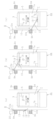
続いて、前記付着防止剤噴霧装置8にて、比較的小型(例えば4tサイズ)の搬送車両4aの荷台7へ付着防止剤を噴霧する場合について図1~図6に基づいて説明する。先ず、図1~図2及び図6の(a)に示すように、待機状態にある付着防止剤噴霧装置8では、搬送車両4aが通路5内に進入するのを妨げないように、旋回アーム13を通路5一側部側に旋回して退避させておくと共に、走行台車11を走行レール10の基端部10a(搬送車両4aがバックで通路5内に進入する方向から見て最深部側)に移動させておく。そして、この状態で搬送車両4aを通路5内にバックで進入させ、所定位置(上位のミキサ3から排出されるアスファルト合材を、車両後方の荷台7の後部側で受け止められる位置)に停車・待機させる。このとき、前記荷台高さセンサ18では、待機中の前記搬送車両4aの荷台7(床面7a)高さを検出する。
Next, the case where the adhesion prevention
なお、アスファルト合材の受け止め位置を荷台7中央部とせずに荷台7の後部側とするのは、荷台7全体に万遍なくアスファルト合材を積み込むためであり、初めに荷台7後部側に積み込んだ後には、運転手は搬送車両4aを若干バックさせてアスファルト合材の受け止め位置を荷台7前方側にずらし、これを繰り返すことで荷台7全体に一定の層厚でアスファルト合材を積み込み可能としている。したがって、付着防止剤の噴霧を行う、アスファルト合材積み込み前の搬送車両4aの初期停車位置は、図面に示されるように通路5入口側に若干偏っていることとなる。
The reason why the asphalt mixture is received at the rear side of the
次いで、図3及び図6の(b)に示すように、前記噴霧制御器20では、前記旋回アーム13を図中X方向である通路5側に旋回(展開)し、かつ前記荷台高さセンサ18の検出結果に基づいて前記旋回アーム13先端部側を図中Z方向へ下降させ、旋回アーム13先端部に吊下した水平桿15ごと搬送車両4aの荷台7内部まで下ろし、前記水平桿15に固着した各噴霧ノズル16a、16bと、搬送車両4aの荷台7の床面7aやあおり板内壁面7bとを近接させる。なお、前記走行台車11を走行レール10の基端部10aに位置させた状態で旋回アーム13を通路5側に旋回後、先端部側を下降させると、待機中の搬送車両4aの荷台7内部の後端部付近(後端部のあおり板より若干前方位置)に前記水平桿15を下ろせるように、走行台車11の位置決めや旋回アーム13の旋回角度等を前記噴霧制御器20に予め設定している。
Next, as shown in Figures 3 and 6(b), the
次いで、図4~図5及び図6の(c)に示すように、前記状態を維持したまま前記各噴霧ノズル16a、16bより付着防止剤を噴霧しながら、前記走行台車11を図中Y方向へ所定速度にて走行させ、搬送車両4aの荷台7の床面7a、及びあおり板内壁面7bの全面に亘って付着防止剤を一様に噴霧していく。
Next, as shown in Figures 4 to 5 and Figure 6 (c), while maintaining the above state, the traveling
そして、前記旋回アーム13先端部に備えた近接センサ19が搬送車両4aの荷台7前端部のあおり板を検知すれば、荷台7終端部と認識して前記走行台車11の走行、及び各噴霧ノズル16a、16bからの付着防止剤の噴霧を停止した後、旋回アーム13先端部側を上昇させて水平桿15を搬送車両4aの荷台7外部へと取り出す。次いで、旋回アーム13を通路5一側部側に旋回させつつ、走行台車11を走行レール10の基端部10aへと後退させ、最初の待機状態に復帰させる。そして、荷台7の全面に付着防止剤を噴霧し終えた搬送車両4aに対し、上位のミキサ3からアスファルト合材を払い出して積み込み、積み込みを終えた前記搬送車両4aは舗装現場へと搬送・出荷する。
When the
次に、前記付着防止剤噴霧装置8にて、比較的大型(例えば10tサイズ)の搬送車両4bの荷台7へ付着防止剤を噴霧する場合について図1~図2、及び図7~図10に基づいて説明する。なお、基本的な動作・制御は前記した小型の搬送車両4aの場合と略同一であるため、重複する部分の説明は省略する。
Next, the case where the adhesion prevention agent is sprayed onto the
大型の搬送車両4bの場合、荷台7高さが小型の搬送車両4aの場合と比較してより高いものとなるが、前記荷台高さセンサ18による検出結果に基づいてその都度旋回アーム13先端部側を上下動させて調節するため、小型の搬送車両4aの場合と同様に、旋回アーム13先端部に吊下した水平桿15ごと搬送車両4bの荷台7内部まで下ろせ、前記水平桿15に固着した各噴霧ノズル16a、16bと、搬送車両4bの荷台7の床面7aやあおり板内壁面7bとを近接させることができる結果、風の影響を抑えて荷台7表面に付着防止剤を安定して噴霧可能としている。
In the case of a
また、図7~図10に示すように、上位のミキサ3からアスファルト合材を受け取るために停車・待機した際の大型の搬送車両4bの荷台7前端部が、小型の搬送車両4aの場合と比較してプラント本体1の高架台2の脚柱9b、9dよりも前方側(通路5入口側)に大きく突出することとなる。このとき、走行台車11上の旋回アーム13を通路5側へ約90度(通路5と略直交方向に)旋回させる構成とした場合、走行レール10を前記突出分だけ通路5前方側に大きく延長させる必要が生じるが、その場合には搬送車両4bの走行の邪魔となって作業安全上好ましくない。
As shown in Figures 7 to 10, when the
そこで、本実施例では、前記旋回アーム13と水平桿15とを、平面視でそれぞれの長手方向が所定角度(例えば約30~60度程度)を形成するように連結し、前記旋回アーム13を通路5側へ旋回させて前記水平桿15の長手方向が搬送車両4bの荷台7の幅方向と略一致した際(このとき旋回アーム13は平面視で通路5前方側へ傾斜している状態)、走行台車11の位置に対して水平桿15位置が通路5前方側に突出する構成としている。これにより、前記走行台車11が走行レール10の終端部10b(通路5入口部)に到達した際に、水平桿15を搬送車両4bの荷台7前端部に近接させることができ、前記のような走行レール10の延長が不要となって作業安全上より好ましいものとなる。
In this embodiment, the
このように、本発明に係る付着防止剤噴霧装置8にあっては、前記噴霧ノズル16a、16bと搬送車両4a、4bの荷台7とを近接状態に維持しながら付着防止剤を噴霧可能な構成としたので、例え強風下でも付着防止剤を荷台7に安定して噴霧することができ、周辺環境の汚損や付着防止剤の無駄を抑制できる。
In this way, the anti-adhesion
なお、本実施例では、アスファルトプラントのプラント本体1直下に配される通路5に進入する搬送車両4a、4bに対して付着防止剤を噴霧する場合について説明したが、前記プラント本体1で製造したアスファルト合材を一時的に貯蔵する、アスファルト合材サイロの直下に配される通路に侵入する搬送車両4a、4bに対して付着防止剤を噴霧する場合にも同様に適用することができる。
In this embodiment, the case where an anti-adhesion agent is sprayed onto
本発明は、アスファルトプラントのプラント本体やアスファルト合材サイロに限らず、アスファルト合材を搬送する搬送車両に対して付着防止剤を噴霧する場合において広く利用できる。 The present invention can be widely used not only for the plant body of an asphalt plant or an asphalt mixture silo, but also for spraying an adhesion inhibitor onto a transport vehicle that transports asphalt mixture.
1…プラント本体 2…高架台
3…ミキサ 4a、4b…搬送車両
5…通路 7…荷台
7a…床面(荷台) 7b…あおり板内壁面7b(荷台)
8…付着防止剤噴霧装置 9a~9d…脚柱(高架台)
10…走行レール 11…走行台車
12…軸支部(鉛直軸) 13…旋回アーム
15…水平桿 16a、16b…噴霧ノズル
17…ヒータ 18、18’…荷台高さセンサ
19…近接センサ 20…噴霧制御器
REFERENCE SIGNS LIST 1: Plant body 2: Elevated platform 3:
8: Anti-adhesion
REFERENCE SIGNS LIST 10: Traveling rail 11: Traveling cart 12: Axle support (vertical axis) 13: Swivel arm 15:
Claims (3)
Priority Applications (1)
| Application Number | Priority Date | Filing Date | Title |
|---|---|---|---|
| JP2020164010A JP7561561B2 (en) | 2020-09-29 | 2020-09-29 | Anti-adhesion agent spraying device |
Applications Claiming Priority (1)
| Application Number | Priority Date | Filing Date | Title |
|---|---|---|---|
| JP2020164010A JP7561561B2 (en) | 2020-09-29 | 2020-09-29 | Anti-adhesion agent spraying device |
Publications (2)
| Publication Number | Publication Date |
|---|---|
| JP2022056157A JP2022056157A (en) | 2022-04-08 |
| JP7561561B2 true JP7561561B2 (en) | 2024-10-04 |
Family
ID=80998722
Family Applications (1)
| Application Number | Title | Priority Date | Filing Date |
|---|---|---|---|
| JP2020164010A Active JP7561561B2 (en) | 2020-09-29 | 2020-09-29 | Anti-adhesion agent spraying device |
Country Status (1)
| Country | Link |
|---|---|
| JP (1) | JP7561561B2 (en) |
Citations (6)
| Publication number | Priority date | Publication date | Assignee | Title |
|---|---|---|---|---|
| JP3100967U (en) | 2003-10-10 | 2004-06-03 | 璋三 池田 | Heavy oil spraying device and bucket used for heavy oil spraying device |
| US20080185455A1 (en) | 2007-01-05 | 2008-08-07 | Bg Chemical, Lp | Asphalt release agent automated spray system |
| JP2010064700A (en) | 2008-09-12 | 2010-03-25 | Abetec Kk | Automatic/manual selection-type vehicle washing device |
| JP2014148179A (en) | 2013-01-31 | 2014-08-21 | Mk Seiko Co Ltd | Vehicle washer |
| JP2014233645A (en) | 2013-05-30 | 2014-12-15 | アネスト岩田株式会社 | Spray gun |
| JP2019157396A (en) | 2018-03-08 | 2019-09-19 | 大林道路株式会社 | Adhesion inhibitor spraying device |
Family Cites Families (1)
| Publication number | Priority date | Publication date | Assignee | Title |
|---|---|---|---|---|
| JPH07117635A (en) * | 1993-10-27 | 1995-05-09 | Shin Meiwa Ind Co Ltd | Rail vehicle cleaning equipment |
-
2020
- 2020-09-29 JP JP2020164010A patent/JP7561561B2/en active Active
Patent Citations (6)
| Publication number | Priority date | Publication date | Assignee | Title |
|---|---|---|---|---|
| JP3100967U (en) | 2003-10-10 | 2004-06-03 | 璋三 池田 | Heavy oil spraying device and bucket used for heavy oil spraying device |
| US20080185455A1 (en) | 2007-01-05 | 2008-08-07 | Bg Chemical, Lp | Asphalt release agent automated spray system |
| JP2010064700A (en) | 2008-09-12 | 2010-03-25 | Abetec Kk | Automatic/manual selection-type vehicle washing device |
| JP2014148179A (en) | 2013-01-31 | 2014-08-21 | Mk Seiko Co Ltd | Vehicle washer |
| JP2014233645A (en) | 2013-05-30 | 2014-12-15 | アネスト岩田株式会社 | Spray gun |
| JP2019157396A (en) | 2018-03-08 | 2019-09-19 | 大林道路株式会社 | Adhesion inhibitor spraying device |
Also Published As
| Publication number | Publication date |
|---|---|
| JP2022056157A (en) | 2022-04-08 |
Similar Documents
| Publication | Publication Date | Title |
|---|---|---|
| US9636843B2 (en) | Mobile concrete mixing plant | |
| US10017097B2 (en) | Mobile transfer station for flowable material | |
| US20240082864A1 (en) | Device for discharging multi-component adhesives onto a granular mixture discharging method, and use of the device | |
| AU2002310150C1 (en) | Roadway paving system and method including roadway paving vehicle and supply truck | |
| US20160214842A1 (en) | Unique roadworthy sidewalk boom trailer, having on-site interchangeable boom, on-site interchangeable ladder, and on-site interchangeable catwalk sized to access narrow openings and nooks over and under bridges | |
| US9682352B2 (en) | Feed delivery device | |
| JP7561561B2 (en) | Anti-adhesion agent spraying device | |
| CN103935278B (en) | Half tilts container uninstalling system | |
| JP7481792B2 (en) | Anti-adhesion agent spraying device | |
| US20070295581A1 (en) | Transport discharge material flow regulation device and method | |
| US20110064551A1 (en) | Pull and lift system for transporting roofing materials | |
| CN104339458A (en) | Concrete aggregate feeding and storing system | |
| US20070297883A1 (en) | Bulk material unloading system and method | |
| US11858480B2 (en) | Ready mix truck wash system | |
| JP7650495B2 (en) | Anti-adhesion agent spraying device for asphalt mixture transport vehicles | |
| KR102561676B1 (en) | Snow-melting agent sprayer mounted on the dump truck | |
| JPH059904A (en) | Mixture delivering method for asphalt mixture silo | |
| US3322289A (en) | Loading, storage and dispensing apparatus for use with a bituminous mixing plant | |
| KR20240001475A (en) | Raw material transfering apparatus and position adjustment method thereof | |
| WO2015000019A1 (en) | A pipeline padder | |
| KR102753197B1 (en) | Raw material transfering apparatus and cleaning method thereof | |
| CN216915646U (en) | Movable hydraulic lifting device for port funnel | |
| CN111959367A (en) | Building engineering is with carrying discharge apparatus with spraying dust fall function | |
| AU2015271944B2 (en) | Vehicle access device | |
| AU2021210581A1 (en) | Sprayer for spreading product(s) |
Legal Events
| Date | Code | Title | Description |
|---|---|---|---|
| A621 | Written request for application examination |
Free format text: JAPANESE INTERMEDIATE CODE: A621 Effective date: 20230921 |
|
| A131 | Notification of reasons for refusal |
Free format text: JAPANESE INTERMEDIATE CODE: A131 Effective date: 20240327 |
|
| A977 | Report on retrieval |
Free format text: JAPANESE INTERMEDIATE CODE: A971007 Effective date: 20240327 |
|
| A601 | Written request for extension of time |
Free format text: JAPANESE INTERMEDIATE CODE: A601 Effective date: 20240527 |
|
| A521 | Request for written amendment filed |
Free format text: JAPANESE INTERMEDIATE CODE: A523 Effective date: 20240725 |
|
| TRDD | Decision of grant or rejection written | ||
| A01 | Written decision to grant a patent or to grant a registration (utility model) |
Free format text: JAPANESE INTERMEDIATE CODE: A01 Effective date: 20240910 |
|
| A61 | First payment of annual fees (during grant procedure) |
Free format text: JAPANESE INTERMEDIATE CODE: A61 Effective date: 20240924 |
|
| R150 | Certificate of patent or registration of utility model |
Ref document number: 7561561 Country of ref document: JP Free format text: JAPANESE INTERMEDIATE CODE: R150 |