以下、実施の形態に係る灯具3及び照明装置1等について図面等を参照しながら説明する。なお、明細書に示す構成要素の形態は、あくまで例示であってこれらの記載に限定されるものではない。また、図1を含む以下の図面では、各構成部材の相対的な寸法の関係及び形状等が実際のものとは異なる場合がある。また、断面図では、視認性に鑑みて、一部の図において、ハッチングを省略している。また、以下の図面において、同一の符号を付したものは、同一、又はこれに相当するものであり、このことは明細書の全文において共通することとする。ここで、以下の説明において、理解を容易にするために方向を表す用語或いは向きを適宜用いるが、それらの表記は、説明の便宜上用いる記載であり、装置、器具、或いは部品等の配置、方向及び向きを限定するものではない。方向或いは向きを表す用語は、例えば、上、下、右、左、前、後、表、又は裏等がある。
The following describes the lamp 3 and the lighting device 1 according to the embodiment with reference to the drawings. The configurations of the components shown in the specification are merely examples and are not limited to these descriptions. In addition, in the following drawings including FIG. 1, the relative dimensional relationship and shape of each component may differ from the actual one. In addition, in the cross-sectional views, hatching is omitted in some drawings in consideration of visibility. In addition, in the following drawings, the same reference numerals are assigned to the same or equivalent parts, and this is common throughout the entire specification. Here, in the following description, terms or orientations that indicate directions are used as appropriate to facilitate understanding, but these notations are used for the convenience of explanation and do not limit the arrangement, direction, or orientation of devices, appliances, or parts. Terms that indicate directions or orientations include, for example, up, down, right, left, front, back, front, or back.
実施の形態1.
[照明装置1]
図1は、実施の形態1に係る照明装置1の一構成例を示す斜視図である。図2は、図1に示した照明装置1の分解斜視図である。照明装置1は、照明空間を照明できる位置に設置され、照明空間を照らす装置である。照明空間とは、照明装置1が設置される空間であり、例えば居住空間、倉庫等の内部空間、ビル或いは公共施設等の内部空間、エレベータ或いは廊下等の共有空間、又は、電車或いは船舶等の乗り物内の空間等を意味している。
Embodiment 1.
[Lighting device 1]
Fig. 1 is a perspective view showing a configuration example of a lighting device 1 according to embodiment 1. Fig. 2 is an exploded perspective view of the lighting device 1 shown in Fig. 1. The lighting device 1 is a device that is installed at a position where it can illuminate an illumination space and illuminates the illumination space. The illumination space is a space in which the lighting device 1 is installed, and means, for example, an internal space of a residential space or a warehouse, an internal space of a building or a public facility, a shared space such as an elevator or a corridor, or a space inside a vehicle such as a train or a ship.
照明装置1は、図1及び図2に示すように、器具2と、器具2に対して着脱自在に取り付けられる灯具3とを備えている。照明装置1は、灯具3を照明空間に向けた状態で、被取付部9に取り付けられる。被取付部9は、器具2が取り付けられる取付箇所であり、例えば、天井或いは壁等である。照明装置1は、灯具3を点灯させることによって灯具3から光を照射させ、照明空間を照らす。
As shown in Figs. 1 and 2, the lighting device 1 comprises an appliance 2 and a luminaire 3 that can be attached and detached to the appliance 2. The lighting device 1 is attached to an attachment portion 9 with the luminaire 3 facing the illumination space. The attachment portion 9 is an attachment location where the appliance 2 is attached, such as a ceiling or a wall. The lighting device 1 irradiates light from the luminaire 3 by turning on the luminaire 3, thereby illuminating the illumination space.
照明装置1は、器具端部21が逆富士山型をなしていることから、所謂逆富士タイプと称される照明装置である。照明装置1、器具2及び灯具3はいずれも長尺状に形成されている。なお、以下の説明において、照明装置1の長手側に沿った方向を、第1方向となる長手方向Xとする。また、長手方向Xに直交し、照明装置1の短手側に沿った方向を、第2方向となる短手方向Yとする。そして、長手方向X及び短手方向Yのいずれとも直交する方向を、第3方向となる上下方向Zとする。
The lighting device 1 is a so-called inverted Mount Fuji type lighting device because the fixture end 21 is shaped like an inverted Mount Fuji. The lighting device 1, fixture 2, and luminaire 3 are all formed in an elongated shape. In the following description, the direction along the long side of the lighting device 1 is referred to as the long direction X, which is the first direction. The direction perpendicular to the long direction X and along the short side of the lighting device 1 is referred to as the short direction Y, which is the second direction. The direction perpendicular to both the long direction X and the short direction Y is referred to as the up-down direction Z, which is the third direction.
実施の形態1における上下方向Zは、例えば鉛直方向である。上下方向Zにおいて、照明装置1が取り付けられる被取付部9の側、すなわち天井、又は壁側へ向かう向きを、上向きZ1と呼ぶこととする。そして、上向きZ1と反対側への向きであり、照明装置1から光が照射される照射空間の側への向きを、下向きZ2と呼ぶこととする。ここで、上向きZ1は、灯具3が器具2に取り付けられる向きである。また、下向きZ2は、灯具3が器具2から取り外される向きである。
In the first embodiment, the up-down direction Z is, for example, the vertical direction. In the up-down direction Z, the direction toward the mounting portion 9 to which the lighting device 1 is mounted, i.e., the ceiling or wall, is referred to as the upward direction Z1. The direction opposite to the upward direction Z1, toward the side of the illumination space to which light is irradiated from the lighting device 1, is referred to as the downward direction Z2. Here, the upward direction Z1 is the direction in which the lighting device 3 is mounted to the device 2. The downward direction Z2 is the direction in which the lighting device 3 is removed from the device 2.
[器具2]
器具2は、被取付部9に直接取り付けられる、所謂直付け型の照明器具である。器具2は、例えば、被取付部9に設けられた吊ボルト等の取付具(図示は省略)に取り付けられる。また、器具2は、灯具3が取り付けられる被取付部材である。そのため、器具2は、灯具装着具とも称する。器具2は、器具2に取り付けられた灯具3を保持し、灯具3に電力を供給する。
[Apparatus 2]
The fixture 2 is a so-called direct-attach type lighting fixture that is directly attached to the attachment portion 9. The fixture 2 is attached to a fixture (not shown) such as a hanging bolt provided on the attachment portion 9. The fixture 2 is also an attachment member to which the lamp 3 is attached. Therefore, the fixture 2 is also called a lamp attachment fixture. The fixture 2 holds the lamp 3 attached to the fixture 2 and supplies power to the lamp 3.
器具2は、後述する灯具装着部22(図2参照)の短手方向Yにおける両側にV字状になるように設けられた2つの傾斜面部202を有することから、所謂V字タイプと称される照明器具である。器具2は、これに限らず、傾斜面部202が設けられないトラフタイプ、笠付タイプ等の直付型照明器具の他、埋込型照明器具であってもよい。
The fixture 2 is a so-called V-type lighting fixture because it has two inclined surface portions 202 arranged in a V shape on both sides in the short direction Y of the lamp mounting portion 22 (see FIG. 2) described later. The fixture 2 is not limited to this, and may be a directly attached lighting fixture such as a trough type or a shaded type that does not have an inclined surface portion 202, or a recessed lighting fixture.
器具2は、金属製の板材(板金)を用いて、折り曲げ、ロールフォーミング、又は、プレスといった加工を施すことによって、予め設計された形状に形成される。或いは、器具2は、金属材料を用いた押出成形、又は3Dプリンティングのような三次元造形等の製造方法で形成されてもよい。
The device 2 is formed into a pre-designed shape by processing such as bending, roll forming, or pressing a metal plate (sheet metal). Alternatively, the device 2 may be formed by a manufacturing method such as extrusion molding using a metal material or three-dimensional modeling such as 3D printing.
器具2は、長尺状の長手方向Xに延びる器具本体部20と、器具本体部20の長手方向Xにおける両端部に取り付けられた器具端部21とを有する。器具端部21は、図1及び図2に示すように、台形形状を有している。器具端部21は、台形形状の長い方の辺が被取付部9の側に、台形形状の短い方の辺が照明空間の側に配置されている。
The fixture 2 has a fixture body 20 that extends in the longitudinal direction X and fixture end portions 21 that are attached to both ends of the fixture body 20 in the longitudinal direction X. As shown in Figs. 1 and 2, the fixture end portions 21 have a trapezoidal shape. The longer side of the trapezoidal shape of the fixture end portion 21 is disposed on the side of the mounting portion 9, and the shorter side of the trapezoidal shape is disposed on the side of the lighting space.
(器具本体部20)
器具本体部20は、図2に示すように、天面部200と、1対の側面部201と、1対の傾斜面部202とを有している。天面部200は、長手方向Xに沿って長尺かつ平板状に形成されている。天面部200は、器具本体部20の底面部とも称する。天面部200には、ネジ孔(図示は省略)及び電線挿通孔(図示は省略)が形成されている。天面部200は、天井等の被取付部9に対して略平行になるように配置される。
(Apparatus body 20)
As shown in Fig. 2, the device main body 20 has a top surface 200, a pair of side surfaces 201, and a pair of inclined surfaces 202. The top surface 200 is formed in a long, flat plate shape along the longitudinal direction X. The top surface 200 is also referred to as a bottom surface of the device main body 20. A screw hole (not shown) and an electric wire insertion hole (not shown) are formed in the top surface 200. The top surface 200 is disposed so as to be approximately parallel to the mounting portion 9, such as a ceiling.
1対の側面部201は、天面部200の短手方向Yの両端にそれぞれ配置されている。また、1対の傾斜面部202は、1対の側面部201の外側になるように、天面部200の短手方向Yの両端にそれぞれ配置されている。このように、器具本体部20において、1対の側面部201は内側に配置され、1対の傾斜面部202は外側に配置されている。1対の側面部201と、1対の傾斜面部202とは、器具本体部20の器具側部を構成している。
The pair of side portions 201 are disposed at both ends of the top surface portion 200 in the short direction Y. The pair of inclined surface portions 202 are disposed at both ends of the top surface portion 200 in the short direction Y so as to be on the outside of the pair of side portions 201. In this way, in the device main body portion 20, the pair of side portions 201 are disposed on the inside, and the pair of inclined surface portions 202 are disposed on the outside. The pair of side portions 201 and the pair of inclined surface portions 202 constitute the device side portions of the device main body portion 20.
側面部201の短手方向Yにおける両端のうち、一端は天面部200の側に配置され、他端は、天面部200と反対側の照明空間の側に配置される。側面部201の短手方向Yにおける一端は、天面部200の短手方向Yにおける一端に連結され、側面部201の短手方向Yにおける他端は、傾斜面部202の短手方向Yにおける一端に連結されている。側面部201は、天面部200の長手方向Xに沿って、天面部200の側縁部の全長に亘って設けられている。側面部201は、天面部200の側縁部から、被取付部9と離れる方向に向かって立ち上がっている。すなわち、側面部201は、天面部200の側縁部から、下向きZ2に突出している。
Of both ends of the side portion 201 in the short direction Y, one end is disposed on the side of the top surface portion 200, and the other end is disposed on the side of the lighting space opposite the top surface portion 200. One end of the side portion 201 in the short direction Y is connected to one end of the top surface portion 200 in the short direction Y, and the other end of the side portion 201 in the short direction Y is connected to one end of the inclined surface portion 202 in the short direction Y. The side portion 201 is provided along the longitudinal direction X of the top surface portion 200 over the entire length of the side edge of the top surface portion 200. The side portion 201 rises from the side edge of the top surface portion 200 in a direction away from the mounting portion 9. That is, the side portion 201 protrudes downward Z2 from the side edge of the top surface portion 200.
傾斜面部202は、図1に示すように、器具本体部20の傾斜部であり、照明装置1及び器具2の外観となる意匠部分である。傾斜面部202は、器具本体部20の長手方向Xに沿って延びている。傾斜面部202は、器具本体部20の側面を構成している。傾斜面部202の短手方向Yにおける一端は、上述したように、側面部201の短手方向Yにおける照明空間の側の一端に連結されている。傾斜面部202は、側面部201の長手方向Xに沿って、側面部201の短手方向Yの一端の全長に亘って設けられている。傾斜面部202は、後述する灯具装着部22の短手方向Yにおける両側に設けられている。
As shown in FIG. 1, the inclined surface portion 202 is an inclined portion of the fixture body portion 20, and is a design part that determines the appearance of the lighting device 1 and the fixture 2. The inclined surface portion 202 extends along the longitudinal direction X of the fixture body portion 20. The inclined surface portion 202 constitutes the side surface of the fixture body portion 20. As described above, one end of the inclined surface portion 202 in the lateral direction Y is connected to one end of the side portion 201 on the side of the lighting space in the lateral direction Y. The inclined surface portion 202 is provided along the longitudinal direction X of the side portion 201, over the entire length of one end of the side portion 201 in the lateral direction Y. The inclined surface portion 202 is provided on both sides in the lateral direction Y of the lamp attachment portion 22 described later.
傾斜面部202は、天井等の被取付部9に対して傾斜している。すなわち、傾斜面部202は、天面部200に対して傾斜している。傾斜面部202は、側面部201と一体で構成されていてもよい。その場合、傾斜面部202は、側面部201の下端から、斜め上方に向かって折り曲げて形成される。傾斜面部202は、被取付部9に向かうにつれて、側面部201から離れるように形成されている。傾斜面部202は、灯具3から照射される光の一部を反射させて側方に配光する機能を有していてもよい。
The inclined surface portion 202 is inclined with respect to the mounting portion 9, such as a ceiling. That is, the inclined surface portion 202 is inclined with respect to the top surface portion 200. The inclined surface portion 202 may be integral with the side surface portion 201. In this case, the inclined surface portion 202 is formed by bending the lower end of the side surface portion 201 diagonally upward. The inclined surface portion 202 is formed so as to move away from the side surface portion 201 as it moves toward the mounting portion 9. The inclined surface portion 202 may have the function of reflecting a portion of the light emitted from the lighting device 3 and distributing it laterally.
器具本体部20は、図2に示すように、内部に、灯具装着部22を有する。灯具装着部22は、灯具3の少なくとも一部分が収容される空間を形成する。灯具装着部22は、器具本体部20の天面部200及び一対の側面部201によって、凹形状に形成されている。また、灯具装着部22は、器具本体部20の天面部200、一対の側面部201及び一対の器具端部21によって、底面が開口した箱状に形成されている。
As shown in FIG. 2, the fixture body 20 has a lamp mounting section 22 inside. The lamp mounting section 22 forms a space in which at least a portion of the lamp 3 is housed. The lamp mounting section 22 is formed in a concave shape by the top surface 200 and a pair of side surfaces 201 of the fixture body 20. The lamp mounting section 22 is also formed in a box shape with an open bottom by the top surface 200, the pair of side surfaces 201, and the pair of fixture ends 21 of the fixture body 20.
灯具装着部22には、2つのバネ23と、端子台24と、器具側電線25とが設けられている。
The lamp mounting section 22 is provided with two springs 23, a terminal block 24, and a fixture side electric wire 25.
バネ23は、器具側連結具である。2つのバネ23は、器具本体部20の長手方向Xに沿って対になるように、天面部200に互いに離間して取り付けられている。バネ23は、灯具3が器具2に取り付けられる際に、灯具3に設けられた灯具側連結具であるバネ受具60と連結する。すなわち、バネ23とバネ受具60とが連結することによって、灯具3は器具2に取り付けられる。バネ23は、バネ受具60と係合することで灯具3を支持する。
The springs 23 are fixture-side connectors. The two springs 23 are attached to the top surface 200 at a distance from each other so as to form a pair along the longitudinal direction X of the fixture body 20. When the lamp 3 is attached to the fixture 2, the springs 23 connect to a spring receiver 60, which is a fixture-side connector provided on the lamp 3. In other words, the lamp 3 is attached to the fixture 2 by connecting the springs 23 to the spring receiver 60. The springs 23 support the lamp 3 by engaging with the spring receiver 60.
端子台24は、外部電源から供給された電力を灯具3に供給する中継装置となる。器具側電線25は、端子台24に電気的に接続されている。器具側電線25は、電力供給線及び制御信号線を含んでいる。器具2の外部から供給される電力及び制御信号は、端子台24及び器具側電線25を経由して、灯具3の電源部40に伝達される。
The terminal block 24 serves as a relay device that supplies power supplied from an external power source to the lighting fixture 3. The fixture side electric wires 25 are electrically connected to the terminal block 24. The fixture side electric wires 25 include a power supply line and a control signal line. Power and control signals supplied from outside the fixture 2 are transmitted to the power supply unit 40 of the lighting fixture 3 via the terminal block 24 and the fixture side electric wires 25.
(器具端部21)
1対の器具端部21は、器具本体部20の長手方向Xにおける両端に配置された板状の部材である。器具端部21の主面は、図2に示すように、台形形状を有しており、上辺の長さが、下辺の長さより長い。器具端部21は、天面部200の長手方向Xにおける両端部及び傾斜面部202の長手方向Xにおける両端部に当接して連結されている。また、器具端部21のそれぞれには、ノックアウト部210が形成されている。
(Instrument End 21)
The pair of instrument ends 21 are plate-like members arranged at both ends in the longitudinal direction X of the instrument body 20. As shown in Fig. 2, the main surface of the instrument end 21 has a trapezoidal shape, with the length of the upper side being longer than the length of the lower side. The instrument end 21 is abutted against and connected to both ends in the longitudinal direction X of the top surface 200 and both ends in the longitudinal direction X of the inclined surface 202. In addition, each of the instrument ends 21 is formed with a knockout portion 210.
ノックアウト部210は、器具端部21にノックアウト加工が施された部分である。ノックアウト部210は、器具端部21から簡単に取り外すことができるように形成されている。作業員は、照明装置を施工する際に、ノックアウト部210を叩いて外したり、或いは、切り取ったりすることにより、現場で簡単に器具端部21に貫通部を設けることができる。ノックアウト部210は、器具端部21から取り外されることで、例えば、隣接する複数の器具2どうしで受け渡しされる電源線(図示は省略)の挿入口として機能する。ノックアウト部210は、器具本体部20の長手方向Xにおける両端に配置されているため、作業員は、2つのノックアウト部210のうち、いずれか1つを選択して、器具端部21に貫通部を設けることもできる。この場合は、器具端部21に複数のノックアウト部210を設けておくことで、作業員が現場の施工環境に応じて、器具2に挿入される電力線の挿入口を自由に選択することができる。
The knockout portion 210 is a portion of the fixture end 21 that has been subjected to knockout processing. The knockout portion 210 is formed so as to be easily detachable from the fixture end 21. When constructing the lighting device, a worker can easily provide a penetration portion in the fixture end 21 at the site by knocking out the knockout portion 210 or cutting it off. When the knockout portion 210 is removed from the fixture end 21, it functions as an insertion port for a power line (not shown) that is passed between adjacent fixtures 2, for example. Since the knockout portion 210 is disposed at both ends in the longitudinal direction X of the fixture body 20, the worker can select one of the two knockout portions 210 to provide a penetration portion in the fixture end 21. In this case, by providing multiple knockout portions 210 in the fixture end 21, the worker can freely select the insertion port for the power line to be inserted into the fixture 2 according to the construction environment at the site.
[灯具3]
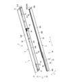
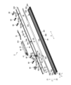
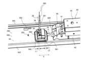
図3は、図2に示した灯具3を被取付部9の側から見たときの斜視図である。図4は、図3に示した灯具3の分解斜視図である。図5は、実施の形態1に係る保持具50を説明するための灯具3の部分斜視図である。図5においては、図1~図4とは、上下方向Zが逆向きになっている。すなわち、図1~図4の下向きZ2が、図5では上向きの矢印で示されている。図1~図5を用いて灯具3について説明する。灯具3は、器具2の灯具装着部22に取り付けられた状態で、照明空間に向かって光を照射する。灯具3は、照明具、或いはライトユニット等とも称する。
[Lamp 3]
FIG. 3 is a perspective view of the lamp 3 shown in FIG. 2 as viewed from the side of the mounting portion 9. FIG. 4 is an exploded perspective view of the lamp 3 shown in FIG. 3. FIG. 5 is a partial perspective view of the lamp 3 for explaining the holder 50 according to the first embodiment. In FIG. 5, the up-down direction Z is opposite to that in FIGS. 1 to 4. That is, the downward direction Z2 in FIGS. 1 to 4 is indicated by an upward arrow in FIG. 5. The lamp 3 will be explained using FIGS. 1 to 5. The lamp 3 irradiates light toward the illumination space when attached to the lamp mounting portion 22 of the device 2. The lamp 3 is also called a lighting device or a light unit.
灯具3は、上述したように、器具2に取り付けられて使用される。実施の形態1の灯具3は、長尺状に形成されており、器具2に対して着脱自在に装着される。灯具3は、図2に示すように、光源ユニット30と、透光性のある外郭部39とを有している。また、灯具3は、図3に示すように、バネ受具60と、灯具側電線70と、電線配置具80と、保持具50とを有している。
As described above, the lighting fixture 3 is attached to the fixture 2 for use. The lighting fixture 3 of the first embodiment is formed in an elongated shape and is detachably attached to the fixture 2. As shown in FIG. 2, the lighting fixture 3 has a light source unit 30 and a translucent outer casing 39. As shown in FIG. 3, the lighting fixture 3 also has a spring receiver 60, a lighting fixture side electric wire 70, an electric wire arrangement device 80, and a holder 50.
(光源ユニット30)
光源ユニット30は、図2~図5に示すように、点灯電力を生成する電源部40と、光源部31(図2、図4及び図5参照)とを有する。光源ユニット30は、さらに、光源部31が配置される台座となる基台34(図3~図5参照)と、電源部40から光源部31に点灯電力を供給する給電線38(図3~図5参照)とを有する。
(Light source unit 30)
2 to 5, the light source unit 30 has a power supply unit 40 that generates lighting power, and a light source unit 31 (see FIGS. 2, 4, and 5). The light source unit 30 further has a base 34 (see FIGS. 3 to 5) that serves as a base on which the light source unit 31 is placed, and a power supply line 38 (see FIGS. 3 to 5) that supplies lighting power from the power supply unit 40 to the light source unit 31.
(電源部40)
電源部40は、電源装置及び制御ユニットを構成している。電源部40には、器具2に配置された端子台24(図2参照)を介して商用電源等の外部電源からの外部電力が供給される。電源部40は、当該外部電力を、光源部31の発光部33を点灯させるための点灯電力に変換して、光源部31(図2参照)に供給する。
(Power supply unit 40)
The power supply unit 40 constitutes a power supply device and a control unit. External power from an external power source such as a commercial power source is supplied to the power supply unit 40 via a terminal block 24 (see FIG. 2) arranged on the device 2. The power supply unit 40 converts the external power into lighting power for lighting the light emitting unit 33 of the light source unit 31, and supplies the lighting power to the light source unit 31 (see FIG. 2).
実施の形態1の照明装置1では、図4及び図5に示すように、電源部40は、電源装置44(図20及び図21参照)と、この電源装置44を収容するために、電源ケース42と電源カバー43とを有している。電源ケース42及び電源カバー43は、内部に電源装置44を配置する電源筐体である。そして、電源ケース42は電源筐体の本体部であり、電源カバー43は電源筐体の蓋部である。電源ケース42は、図4に示すように、基台34の第2面342に、ネジ等の固定具85を用いて取り付けられる。これにより、電源部40は、光源部31等と共に灯具装着部22に収容される。基台34には、図4に示すように、ネジ挿通孔354と電源固定部356とが設けられている。電源固定部356は、上面視で円形形状を有しており、その中心部にネジ挿通孔354が形成されている。図4に示すように、固定具85が上向きZ1の方向にネジ挿通孔354に挿入されて締結されることで、電源部40は基台34に固定される。電源部40は、長手方向Xに延びる直方体の箱形形状で、長手方向Xにおける一端に、出力端子41が設けられている。出力端子41は、後述する給電線38の芯線である導体382に電気的に接続される。電源部40は、灯具3が器具2に装着された状態で、基台34の第2面342と器具2との間に配置される。
In the lighting device 1 of the first embodiment, as shown in FIG. 4 and FIG. 5, the power supply unit 40 has a power supply unit 44 (see FIG. 20 and FIG. 21), and a power supply case 42 and a power supply cover 43 to accommodate the power supply unit 44. The power supply case 42 and the power supply cover 43 are a power supply housing in which the power supply unit 44 is arranged. The power supply case 42 is the main body of the power supply housing, and the power supply cover 43 is the cover of the power supply housing. The power supply case 42 is attached to the second surface 342 of the base 34 using a fastener 85 such as a screw, as shown in FIG. 4. As a result, the power supply unit 40 is accommodated in the lamp mounting portion 22 together with the light source unit 31 and the like. The base 34 is provided with a screw insertion hole 354 and a power supply fixing portion 356, as shown in FIG. 4. The power supply fixing portion 356 has a circular shape when viewed from above, and the screw insertion hole 354 is formed in the center thereof. As shown in FIG. 4, the fixing device 85 is inserted into the screw insertion hole 354 in the upward Z1 direction and fastened, thereby fixing the power supply unit 40 to the base 34. The power supply unit 40 has a rectangular box shape extending in the longitudinal direction X, and an output terminal 41 is provided at one end in the longitudinal direction X. The output terminal 41 is electrically connected to a conductor 382, which is the core wire of the power supply line 38 described below. The power supply unit 40 is disposed between the second surface 342 of the base 34 and the fixture 2 when the lighting fixture 3 is attached to the fixture 2.
また、電源部40は、後述する図20~図22に示すように、電源ケース42に設けられた差込片420を有している。差込片420は、電源ケース42の長手方向Xの一端から、長手方向Xに向かって突出した突起部である。差込片420は、電源ケース42の長手方向Xの両端のうち、出力端子41が配置されている側の一端に配置される。電源部40は基台34に固定される際に、電源部40に設けられた差込片420が、後述する保持具50の電源保持部556(図22参照)に差し込まれる。これにより、電源部40は、固定具85だけでなく、保持具50によっても基台34に固定されるので、基台34からの脱落がより確実に防止される。なお、電源部40と後述する保持具50との結合方法については、図20~図23を用いて後述する。
The power supply unit 40 also has an insertion piece 420 provided on the power supply case 42, as shown in Figs. 20 to 22, which will be described later. The insertion piece 420 is a protrusion that protrudes from one end of the power supply case 42 in the longitudinal direction X toward the longitudinal direction X. The insertion piece 420 is provided at one end of the power supply case 42 in the longitudinal direction X on the side where the output terminal 41 is provided. When the power supply unit 40 is fixed to the base 34, the insertion piece 420 provided on the power supply unit 40 is inserted into the power supply holding portion 556 (see Fig. 22) of the holder 50, which will be described later. As a result, the power supply unit 40 is fixed to the base 34 not only by the fixing device 85 but also by the holder 50, so that it is more reliably prevented from falling off the base 34. The method of connecting the power supply unit 40 to the holder 50, which will be described later, will be described later with reference to Figs. 20 to 23.
(光源部31)
光源部31は、発光ユニットであり、光を発する。光源部31は、図5に示すように、電源部から供給される点灯電力によって光を出射する発光部33と、発光部33が設けられた基板32と、点灯電力を発光部33に供給する受電部324とを有する。なお、発光部33は、図2に示すように、基板32の一面である実装面に設けられている。
(Light source unit 31)
The light source unit 31 is a light-emitting unit that emits light. As shown in Fig. 5, the light source unit 31 includes a light-emitting unit 33 that emits light using lighting power supplied from a power supply unit, a substrate 32 on which the light-emitting unit 33 is provided, and a power receiving unit 324 that supplies lighting power to the light-emitting unit 33. Note that the light-emitting unit 33 is provided on a mounting surface, which is one surface of the substrate 32, as shown in Fig. 2.
発光部33は、電源部40から給電線38を介して供給される点灯電力を受けて光を出射する。発光部33は、面実装部品である。発光部33は、例えば、発光ダイオード(Light Emitting Diode;LED)素子等の発光素子である。発光部33は、はんだ等の接続部材を用いて基板に実装される。実施の形態1においては、発光部33が発光素子の場合で説明するが、発光部33は発光素子に限らない。例えば、発光部33は、固体レーザ(Solid State Laser)、半導体レーザ(Semiconductor Laser)、有機EL(Electro Luminescence)、或いは、無機EL等の素子を用いてもよい。発光部33は、発光素子と他の光源とが組み合わされたものでもよい。
The light-emitting unit 33 emits light upon receiving lighting power supplied from the power supply unit 40 via the power supply line 38. The light-emitting unit 33 is a surface-mounted component. The light-emitting unit 33 is, for example, a light-emitting element such as a light-emitting diode (LED). The light-emitting unit 33 is mounted on a board using a connecting member such as solder. In the first embodiment, the light-emitting unit 33 is described as being a light-emitting element, but the light-emitting unit 33 is not limited to being a light-emitting element. For example, the light-emitting unit 33 may be an element such as a solid-state laser, a semiconductor laser, an organic electroluminescence (EL), or an inorganic electroluminescence (EL). The light-emitting unit 33 may be a combination of a light-emitting element and another light source.
基板32は、長手方向Xに沿って延びる長尺状に形成されている。基板32は板状形状を有しており、発光部33が配置された一面320と、一面320の反対側の面である他面321とを有する。一面320は、発光部33の実装面であり、照射空間の側の基板32の下面であり、照射空間の側に向く面である。図1に示す構成例では、基板32の一面320には、複数の発光部33が列状に実装されている。ただし、発光部33の実装形態は、当該構成に限定されるものではない。他面321は、発光部33の非実装面であり、基板32の上面である。他面321は、基台34との接合面である。このように、他面321は光源ユニット30において被取付部9の側の面を構成する。
The substrate 32 is formed in an elongated shape extending along the longitudinal direction X. The substrate 32 has a plate-like shape and has one surface 320 on which the light-emitting unit 33 is arranged, and the other surface 321 which is the surface opposite to the one surface 320. The one surface 320 is the mounting surface of the light-emitting unit 33, and is the lower surface of the substrate 32 on the side of the irradiation space, and is the surface facing the side of the irradiation space. In the configuration example shown in FIG. 1, a plurality of light-emitting units 33 are mounted in a row on the one surface 320 of the substrate 32. However, the mounting form of the light-emitting units 33 is not limited to this configuration. The other surface 321 is the non-mounting surface of the light-emitting unit 33 and is the upper surface of the substrate 32. The other surface 321 is the joint surface with the base 34. In this way, the other surface 321 constitutes the surface on the side of the mounting portion 9 in the light source unit 30.
基板32は、リジットタイプ、又はフレキシブルタイプのいずれのタイプを採用しても構わない。基板32は、例えば、ガラス-エポキシ基板(FR-4)、ガラス-コンポジット基板(CEM-3)、紙エポキシ基板(FR-3)、紙フェノール基板(XPC)、或いは、金属ベース基板等が用いられる。基板32は、他面321の側が基台34の第1面341に装着される。より詳細には、基板32は、他面321を基台34の第1面341に対向させた状態で、接着部材87を用いて基台34の第1面341に接着固定される。図示は省略するが、基板32は、基台34に対して、リベット、ネジ等の固定具を用いて固定されてもよいし、基台34の一部を切り起こすなどの加工を施して設けられた基板保持部によって固定されてもよい。
The substrate 32 may be of either a rigid type or a flexible type. For example, a glass-epoxy substrate (FR-4), a glass-composite substrate (CEM-3), a paper-epoxy substrate (FR-3), a paper-phenol substrate (XPC), or a metal-based substrate may be used for the substrate 32. The other surface 321 of the substrate 32 is attached to the first surface 341 of the base 34. More specifically, the substrate 32 is bonded and fixed to the first surface 341 of the base 34 using an adhesive member 87 with the other surface 321 facing the first surface 341 of the base 34. Although not shown, the substrate 32 may be fixed to the base 34 using a fastener such as a rivet or a screw, or may be fixed by a substrate holder provided by cutting and raising a part of the base 34.
基板32には、基板32を貫通する基板貫通孔322が形成されている。基板貫通孔322は、図4及び図5に示すように、給電線38の位置に合わせて形成されている。さらに詳細に言えば、基板貫通孔322は、基板32の一面320に対して垂直な方向、すなわち、上下方向Zにおいて、後述する保持具50の第1案内部543と重なる位置に形成されている。
The substrate 32 is formed with a substrate through hole 322 that penetrates the substrate 32. The substrate through hole 322 is formed to match the position of the power supply line 38, as shown in Figures 4 and 5. More specifically, the substrate through hole 322 is formed in a position that overlaps with a first guide portion 543 of the holder 50 described later in a direction perpendicular to one surface 320 of the substrate 32, i.e., in the vertical direction Z.
基板貫通孔322には、給電線38の一端部380(図5参照)における導体382が挿通される。導体382は、給電線38の芯線である。
The conductor 382 at one end 380 (see FIG. 5) of the power supply line 38 is inserted into the board through hole 322. The conductor 382 is the core wire of the power supply line 38.
基板32には、基板貫通孔322の周囲に受電部324が形成されている。すなわち、受電部324は、基板32に設けられている。受電部324は、基板32において、導体382が接続される接続部である。受電部324は、接続パッドとも称する。給電線38の一端部380における導体382は、はんだ等の接続部材(図示は省略)を用いて受電部324に接続される。受電部324は、電源部40から供給される点灯電力を光源部31に中継する電極の役目を果たす。受電部324は、基板32の一面320及び他面321のうち、少なくともいずれか一方に設けられている。
The power receiving section 324 is formed around the board through hole 322 on the board 32. That is, the power receiving section 324 is provided on the board 32. The power receiving section 324 is a connection section on the board 32 to which the conductor 382 is connected. The power receiving section 324 is also called a connection pad. The conductor 382 at one end 380 of the power supply line 38 is connected to the power receiving section 324 using a connection member such as solder (not shown). The power receiving section 324 serves as an electrode that relays the lighting power supplied from the power supply section 40 to the light source section 31. The power receiving section 324 is provided on at least one of the one surface 320 and the other surface 321 of the board 32.
(基台34)
基台34は、基板32の他面321に対向する面であって光源部31を支持する第1面341と、第1面341の反対側の面であって電源部40を支持する第2面342とを有する。第1面341は基台34のおもて面であり、光源配置面である。第1面341は、下向きZ2の側の面であり、基台34の下面とも称する。第1面341は、照射空間の側の面を構成し、外郭部39の透光部391と対向する。第2面342は、基台34のうら面であり、電源配置面である。第2面342は、上向きZ1の側の面であり、基台34の上面とも称する。第2面342は、照明装置1において被取付部9の側の面を構成し、灯具3が器具2に取り付けられた状態では器具本体部20の天面部200と対向する。基台34の第1面341には、光源部31が取り付けられる。
(Base 34)
The base 34 has a first surface 341 that faces the other surface 321 of the substrate 32 and supports the light source unit 31, and a second surface 342 that faces the opposite side of the first surface 341 and supports the power supply unit 40. The first surface 341 is the front surface of the base 34 and is a light source arrangement surface. The first surface 341 is a surface on the downward Z2 side and is also called the lower surface of the base 34. The first surface 341 constitutes a surface on the side of the irradiation space and faces the translucent portion 391 of the outer casing 39. The second surface 342 is a back surface of the base 34 and is a power supply arrangement surface. The second surface 342 is a surface on the upward Z1 side and is also called the upper surface of the base 34. The second surface 342 constitutes a surface on the side of the attachment portion 9 in the lighting device 1, and faces the top surface 200 of the fixture body 20 when the lamp 3 is attached to the fixture 2. The light source unit 31 is attached to the first surface 341 of the base 34 .
基台34は、長手方向Xに延びた長尺状の構造体である。基台34は、配置部340と、上述した灯具3の外郭部39と組み合わされる側部343とを有する。配置部340は、板状に形成されており、光源部31を支持する第1面341と、電源部40を支持する第2面342とを有する。側部343は、配置部340の第2面342のY方向における端部から、被取付部9に向かって立ち上がっている。そのため、基台34の長手方向Xの端部の形状は、コの字形状になっている。基台34は、光源部31及び電源部40等のための台座であり、光源部31及び電源部40等の支持部材である。基台34は、台座、シャーシ、或いは取付部材とも称する。配置部340は、光源部31及び電源部40等が第1面341或いは第2面342に配置される基部である。
The base 34 is an elongated structure extending in the longitudinal direction X. The base 34 has a placement portion 340 and a side portion 343 that is combined with the outer casing portion 39 of the above-mentioned lighting device 3. The placement portion 340 is formed in a plate shape and has a first surface 341 that supports the light source portion 31 and a second surface 342 that supports the power supply portion 40. The side portion 343 rises from the end of the second surface 342 of the placement portion 340 in the Y direction toward the mounting portion 9. Therefore, the end of the base 34 in the longitudinal direction X has a U-shape. The base 34 is a base for the light source portion 31, the power supply portion 40, etc., and is a support member for the light source portion 31, the power supply portion 40, etc. The base 34 is also called a base, a chassis, or a mounting member. The arrangement section 340 is a base on which the light source section 31, the power supply section 40, etc. are arranged on the first surface 341 or the second surface 342.
図5に示すように、基台34には、基台34の配置部340を貫通する電線挿通孔363が形成されている。電線挿通孔363は、基台34の第1面341と第2面342とを貫く貫通孔である。電線挿通孔363は、電線保持具取付孔とも称する。
As shown in FIG. 5, the base 34 has an electric wire insertion hole 363 formed therein, which penetrates the placement portion 340 of the base 34. The electric wire insertion hole 363 is a through hole that penetrates the first surface 341 and the second surface 342 of the base 34. The electric wire insertion hole 363 is also referred to as an electric wire holder attachment hole.
基台34は、図5に示すように、保持具取付部360を有する。保持具取付部360は、後述する保持具50が取り付けられる部分である。より詳細には、基台34の配置部340に、第2面342の側に突出する突出部361が形成されている。図5においては、基台34の第1面341の側から見ているため、突出部361が窪み部(凹部)となっている。そして、突出部361の先端部である頂部362には、上述した電線挿通孔363が形成されている。突出部361、頂部362及び電線挿通孔363は、保持具取付部360を構成する。
As shown in FIG. 5, the base 34 has a holder attachment portion 360. The holder attachment portion 360 is a portion to which the holder 50 described below is attached. More specifically, a protrusion 361 that protrudes toward the second surface 342 is formed in the placement portion 340 of the base 34. In FIG. 5, the protrusion 361 is a recessed portion (concave portion) because it is viewed from the first surface 341 side of the base 34. The top portion 362, which is the tip of the protrusion 361, has the above-mentioned electric wire insertion hole 363 formed therein. The protrusion 361, the top portion 362, and the electric wire insertion hole 363 constitute the holder attachment portion 360.
頂部362は、第1面341に対して垂直方向(上下方向Z)に視て、すなわち、平面視で、概略四角の枠状に形成されている。また、電線挿通孔363は、頂部362の縁部によって形成されており、平面視で、頂部362の縁部によって四角形状に形成されている。ただし、頂部362及び電線挿通孔363の形状は、保持具50の形状に対応した形状であればよく、当該形状に限定されるものではない。
The top 362 is formed in a generally rectangular frame shape when viewed perpendicularly to the first surface 341 (vertical direction Z), i.e., in a plan view. The wire insertion hole 363 is formed by the edge of the top 362, and is formed in a rectangular shape by the edge of the top 362 in a plan view. However, the shapes of the top 362 and the wire insertion hole 363 need only correspond to the shape of the holder 50, and are not limited to this shape.
突出部361は、配置部340の第2面342の側に突出しており、第1面341の側においては、窪み部分(凹部)を形成する。すなわち、基台34の突出部361においては、頂部362と第1面341との間に段差が形成されている。つまり、頂部362は、第1面341に対して凹んでいる。一方、第2面342の側においては、突出部361は、第2面342に対して隆起する部分を形成している。すなわち、突出部361は、第2面342の側の配置部340において凸状に形成されている。基台34の突出部361においては、頂部362と第2面342との間に段差が形成されている。つまり、頂部362は、第2面342から、上下方向Zの上向きZ1に向かって突出している。
The protrusion 361 protrudes toward the second surface 342 of the arrangement portion 340, and forms a recessed portion (concave portion) on the first surface 341 side. That is, in the protrusion 361 of the base 34, a step is formed between the top 362 and the first surface 341. That is, the top 362 is recessed with respect to the first surface 341. On the other hand, on the second surface 342 side, the protrusion 361 forms a portion that protrudes with respect to the second surface 342. That is, the protrusion 361 is formed in a convex shape on the arrangement portion 340 on the second surface 342 side. In the protrusion 361 of the base 34, a step is formed between the top 362 and the second surface 342. That is, the top 362 protrudes from the second surface 342 toward the upward Z1 in the vertical direction Z.
ここで、基台34は、鋼板等の金属製の板材を折り曲げて形成されているものであり、ロールフォーミング、又はプレス成形等の加工方法等で曲げられ、剛性を得るものである。ただし、基台34は、金属製の板材を折り曲げて形成されたものに限定するものではなく、例えば、樹脂或いはセラミック等、金属以外の材料を用いて形成されたものでもよい。また、基台34は、押出成形、或いは、3Dプリンティングのような三次元造形等の加工方法で加工してもよい。さらに、図示は省略するが、放熱効率(熱放射率)、或いは、光の利用効率(反射率)等を向上させるために、基台34に表面処理を施してもよいし、或いは、基台34に機能部材を敷設してもよい。
Here, the base 34 is formed by bending a metal plate such as a steel plate, and is bent by a processing method such as roll forming or press molding to obtain rigidity. However, the base 34 is not limited to being formed by bending a metal plate, and may be formed using a material other than metal, such as resin or ceramic. The base 34 may also be processed by a processing method such as extrusion molding or three-dimensional modeling such as 3D printing. Furthermore, although not shown, the base 34 may be surface-treated or a functional member may be laid on the base 34 in order to improve the heat dissipation efficiency (thermal emissivity) or the light utilization efficiency (reflectance).
(給電線38)
給電線38は、図4に示すように、電源部40から光源部31に点灯電力を供給するための供給経路となる。給電線38は、図5に示すように、基台34に形成された貫通孔である電線挿通孔363を経由して配置され、電源部40と光源部31とを電気的に接続する。給電線38は、導体382が外装383で覆われて構成されている。外装383は、導体382を覆う電気絶縁性を有する被覆であり、導体382を絶縁する絶縁部である。
(Power supply line 38)
As shown in Fig. 4, the power supply line 38 serves as a supply path for supplying lighting power from the power supply unit 40 to the light source unit 31. As shown in Fig. 5, the power supply line 38 is arranged via a wire insertion hole 363, which is a through hole formed in the base 34, and electrically connects the power supply unit 40 and the light source unit 31. The power supply line 38 is configured by covering a conductor 382 with an exterior 383. The exterior 383 is an electrically insulating coating that covers the conductor 382 and is an insulating part that insulates the conductor 382.
給電線38は、電線挿通孔363を貫通するとともに、一端部380が光源部31と電気的に接続され、他端部381が第2面342の側に配置される。給電線38の一端部380の導体382は、基板32に形成された受電部324に接続される。
The power supply line 38 passes through the power supply line insertion hole 363, and one end 380 is electrically connected to the light source unit 31, and the other end 381 is disposed on the second surface 342 side. The conductor 382 of the one end 380 of the power supply line 38 is connected to the power receiving unit 324 formed on the substrate 32.
保持具取付部360には、電線挿通孔363に嵌め込まれるようにして、保持具50が取り付けられる。保持具50は、電気絶縁性を有している。保持具50は、例えば、樹脂製である。給電線38は、保持具50によって保持される。保持具50は、給電線38と電線挿通孔363の頂部362との間に配置されるので、給電線38と頂部362との接触及び短絡を防止することができる。
The holder 50 is attached to the holder attachment portion 360 so as to be fitted into the electric wire insertion hole 363. The holder 50 has electrical insulation properties. The holder 50 is made of, for example, resin. The power supply line 38 is held by the holder 50. The holder 50 is disposed between the power supply line 38 and the top 362 of the electric wire insertion hole 363, so that contact and short circuit between the power supply line 38 and the top 362 can be prevented.
(外郭部39)
灯具3の外郭部39は、図1及び図4に示すように、灯具3の外郭を形成し、光源部31を覆うカバーである。外郭部39は、基板32を覆うように基台34に取り付けられる。外郭部39は、灯具3の長手方向Xに延びるカバー主部390と、カバー主部390の長手方向Xにおける両端部に設けられたカバー端部395とを有する。
(Outer shell portion 39)
1 and 4, the outer shell 39 of the lamp 3 is a cover that forms the outer shell of the lamp 3 and covers the light source unit 31. The outer shell 39 is attached to the base 34 so as to cover the board 32. The outer shell 39 has a cover main part 390 that extends in the longitudinal direction X of the lamp 3, and cover end parts 395 provided at both ends of the cover main part 390 in the longitudinal direction X.
カバー主部390は、光源ユニット30から出射される光を透過する透光部391と、光源ユニット30と連結される取付部392とを有する。外郭部39は、基台34の第1面341に取り付けられた状態の光源部31を覆う。カバー主部390の長手方向Xの端部の形状(短手方向Yに沿った切断面の形状)は、概略U字形状になっているが、概略コの字形状、或いは概略V字形状等の形状であってもよい。
The cover main part 390 has a light-transmitting part 391 that transmits the light emitted from the light source unit 30, and an attachment part 392 that is connected to the light source unit 30. The outer shell part 39 covers the light source part 31 when it is attached to the first surface 341 of the base 34. The shape of the end part in the longitudinal direction X of the cover main part 390 (the shape of the cut surface along the lateral direction Y) is roughly U-shaped, but it may also be roughly U-shaped or roughly V-shaped, etc.
透光部391は、図1に示すように、少なくとも一部が外部に露出し、光源部31から発せられる光を透過して外部に対する照射を行う部分となる。また、透光部391は、光源部31等を保護する部分となる。このため、透光部391は、光源部31と接触しないように、光源部31との間に空隙を設けた状態で、光源部31に対向するように配置される。
As shown in FIG. 1, at least a portion of the light-transmitting section 391 is exposed to the outside and transmits light emitted from the light source section 31 to irradiate the outside. The light-transmitting section 391 also protects the light source section 31 and the like. For this reason, the light-transmitting section 391 is positioned opposite the light source section 31 with a gap provided between the light-transmitting section 391 and the light source section 31 so that the light-transmitting section 391 does not come into contact with the light source section 31.
取付部392は、基台34に取り付けられる部分である。取付部392は、基台34の短手方向Yにおける両端側から配置部340と側部343とを抱え込むように基台34に取り付けられる。取付部392は、図4に示すように、基台34の第1面341の側に配置されて配置部340を支持する第1取付部393と、基台34の側部343の外側に配置されて側部343の先端部に係合される第2取付部394とを有する。第1取付部393は、支持部ともいい、第2取付部394は、係止部とも称する。
The mounting portion 392 is a portion that is attached to the base 34. The mounting portion 392 is attached to the base 34 so as to embrace the placement portion 340 and the side portion 343 from both ends in the short direction Y of the base 34. As shown in FIG. 4, the mounting portion 392 has a first mounting portion 393 that is arranged on the side of the first surface 341 of the base 34 and supports the placement portion 340, and a second mounting portion 394 that is arranged on the outside of the side portion 343 of the base 34 and engages with the tip portion of the side portion 343. The first mounting portion 393 is also referred to as a support portion, and the second mounting portion 394 is also referred to as a locking portion.
カバー端部395は、灯具3の長手方向Xにおける端部を覆う部分である。ここでは、カバー端部395は、別部材として形成し、溶着、又は接着等により、透光部391に取り付けられるものとする。カバー端部395は、外郭部39の透光部391と基台34の配置部340とによって形成される空間の端面開口に嵌まり込み、その端面開口を塞ぐ。ただし、外郭部39の構成は、当該構成に限定されるものではなく、外郭部39は、カバー端部395と透光部391及び取付部392とが一体に形成されてもよい。
The cover end 395 is a portion that covers the end of the lamp 3 in the longitudinal direction X. Here, the cover end 395 is formed as a separate member and attached to the light-transmitting portion 391 by welding, adhesion, or the like. The cover end 395 fits into the end opening of the space formed by the light-transmitting portion 391 of the outer shell 39 and the arrangement portion 340 of the base 34, and closes the end opening. However, the configuration of the outer shell 39 is not limited to this configuration, and the cover end 395, the light-transmitting portion 391, and the attachment portion 392 of the outer shell 39 may be formed integrally.
外郭部39は、透光性の材料として、ポリカーボネート(PC)、アクリル(PMMA)、或いは、ポリプロピレン(PP)等の合成樹脂、又はガラス等の材料を用いて形成することができる。外郭部39は、これらの材料を用いて、射出成形、ブロー成形、押出成形、或いは、3次元造形といった方法を採用して形成することができる。外郭部39は、照明装置1の仕様に応じて、少なくとも一部に拡散機能、波長弁別機能、或いは遮光機能のいずれかを有してもよい。
The outer shell 39 can be formed using a light-transmitting material such as synthetic resins such as polycarbonate (PC), acrylic (PMMA), or polypropylene (PP), or a material such as glass. The outer shell 39 can be formed using these materials by employing a method such as injection molding, blow molding, extrusion molding, or three-dimensional modeling. At least a part of the outer shell 39 may have any one of a diffusion function, a wavelength discrimination function, or a light blocking function, depending on the specifications of the lighting device 1.
(バネ受具60)
図3に示すバネ受具60は灯具側連結具である。バネ受具60と、器具側連結具であるバネ23(図2参照)とは、灯具3を器具2に取り付ける連結具を構成する。バネ受具60は、基台34の配置部340に取り付けられる。基台34の第2面342の側には、図4に示すように、バネ受具取付孔350とバネ受具固定部351とが設けられている。バネ受具60の一部分がバネ受具取付孔350に挿入されることで、バネ受具60がバネ受具固定部351に固定される。バネ受具60は、配置部340の第2面342から上下方向Zの上向きZ1に向かって立ち上がっており、照明装置1が使用状態にあるときは灯具装着部22に配置される。器具2のバネ23と、灯具3のバネ受具60とが連結されることによって、灯具3は器具2に固定される。
(Spring receiver 60)
The spring receiver 60 shown in FIG. 3 is a lamp side connector. The spring receiver 60 and the spring 23 (see FIG. 2), which is a device side connector, constitute a connector for attaching the lamp 3 to the device 2. The spring receiver 60 is attached to the arrangement portion 340 of the base 34. As shown in FIG. 4, a spring receiver attachment hole 350 and a spring receiver fixing portion 351 are provided on the second surface 342 side of the base 34. The spring receiver 60 is fixed to the spring receiver fixing portion 351 by inserting a part of the spring receiver 60 into the spring receiver attachment hole 350. The spring receiver 60 rises from the second surface 342 of the arrangement portion 340 toward the upward direction Z1 in the vertical direction Z, and is arranged in the lamp mounting portion 22 when the lighting device 1 is in a use state. The spring 23 of the device 2 and the spring receiver 60 of the lamp 3 are connected to each other, so that the lamp 3 is fixed to the device 2.
(灯具側電線70)
図3に示す灯具側電線70は、電力供給線及び制御信号線を含んでいる。照明装置1においては、灯具3の灯具側電線70と器具2の器具側電線25(図2参照)とが電気的に接続されている。
(Light fixture side electric wire 70)
The lamp-side electric wire 70 shown in Fig. 3 includes a power supply line and a control signal line. In the lighting device 1, the lamp-side electric wire 70 of the lamp 3 and the fixture-side electric wire 25 of the fixture 2 (see Fig. 2) are electrically connected to each other.
(電線配置具80)
図3に示す電線配置具80は、電線保護具である。電線配置具80は、基台34における配置部340に取り付けられ、灯具側電線70を保持する。基台34の第2面342には、図4に示すように、電線配置具取付孔352と電線配置具固定部353とが設けられている。電線配置具80は、その一部が電線配置具取付孔352に挿入された状態で、電線配置具固定部353によって固定される。
(Electric wire arrangement tool 80)
The wire arrangement tool 80 shown in Fig. 3 is a wire protector. The wire arrangement tool 80 is attached to an arrangement portion 340 of the base 34, and holds the lamp-side wires 70. As shown in Fig. 4, a wire arrangement tool attachment hole 352 and a wire arrangement tool fixing portion 353 are provided on the second surface 342 of the base 34. The wire arrangement tool 80 is fixed by the wire arrangement tool fixing portion 353 with a portion of the wire arrangement tool inserted into the wire arrangement tool attachment hole 352.
(保持具50)
図3~図5に示すように、保持具50は、第1保持具54と第2保持具55とを有している。図6~図9は、実施の形態1に係る保持具50を説明する斜視図である。図6は、保持具50の第1保持具54の外観を示す斜視図である。図7は、保持具50の第1保持具54の内部構造を示す斜視図である。図8は、保持具50の第2保持具55の外観を示す斜視図である。図9は、保持具50の第2保持具55の内部構造を示す斜視図である。また、図20~図23は、実施の形態1に係る灯具3が有する電源部40が保持具50の電源保持部556に保持されるための構成を示す斜視図である。図20及び図22は、電源部40が保持具50に保持される前の状態を示し、図21及び図23は、電源部40が保持具50に保持された状態を示す。
(Holder 50)
As shown in Figs. 3 to 5, the holder 50 has a first holder 54 and a second holder 55. Figs. 6 to 9 are perspective views for explaining the holder 50 according to the first embodiment. Fig. 6 is a perspective view showing the appearance of the first holder 54 of the holder 50. Fig. 7 is a perspective view showing the internal structure of the first holder 54 of the holder 50. Fig. 8 is a perspective view showing the appearance of the second holder 55 of the holder 50. Fig. 9 is a perspective view showing the internal structure of the second holder 55 of the holder 50. Figs. 20 to 23 are perspective views showing a configuration for holding the power supply unit 40 of the lamp 3 according to the first embodiment in the power supply holding unit 556 of the holder 50. Figs. 20 and 22 show a state before the power supply unit 40 is held by the holder 50, and Figs. 21 and 23 show a state in which the power supply unit 40 is held by the holder 50.
図5~図9、図22、及び図23を用いて実施の形態1に係る保持具50について説明する。
The holder 50 according to embodiment 1 will be described using Figures 5 to 9, 22, and 23.
保持具50は、給電線38を保持するものである。保持具50は、給電線38を保持した状態で基台34に固定する電線固定具であり、電線ホルダとも称する。そして、保持具50は、電源部40の一部を保持した状態で基台34に固定する電源固定具であり、電源クランプとも称する。保持具50は、電気絶縁性を有する材料で形成されている。保持具50は、例えば、樹脂製である。保持具50は、貫通孔である電線挿通孔363を塞ぐように基台34に取り付けられる。
The holder 50 holds the power supply line 38. The holder 50 is a wire fixing device that fixes the power supply line 38 to the base 34 while holding it, and is also called a wire holder. The holder 50 is a power supply fixing device that fixes the power supply unit 40 to the base 34 while holding a part of the power supply unit 40, and is also called a power supply clamp. The holder 50 is made of an electrically insulating material. The holder 50 is made of resin, for example. The holder 50 is attached to the base 34 so as to cover the wire insertion hole 363, which is a through hole.
保持具50には、基台34における第1面341の側に配置される保持具基部と、基台34における第2面342の側に配置される保持具本体部と、保持具基部と保持具本体部とを繋ぎ、電線挿通孔363の内部に配置される保持具接続部とを有する。
The holder 50 has a holder base portion arranged on the first surface 341 side of the base 34, a holder main body portion arranged on the second surface 342 side of the base 34, and a holder connection portion that connects the holder base portion and the holder main body portion and is arranged inside the electric wire insertion hole 363.
実施の形態1では、保持具50は、図5に示すように、電線挿通孔363を貫く方向に沿って2つに分割された第1保持具54及び第2保持具55から構成されており、第1保持具54及び第2保持具55は、基台34の長手方向Xに沿って並んで配置される。そして、図6~図9に示すように、保持具基部は後述する第1基部540と第2基部550とからなり、保持具本体部は後述する第1本体部541と第2本体部551とからなり、保持具接続部は後述する第1接続部542と第2接続部552とからなる。
In the first embodiment, as shown in FIG. 5, the holder 50 is composed of a first holder 54 and a second holder 55 that are divided into two along the direction penetrating the electric wire insertion hole 363, and the first holder 54 and the second holder 55 are arranged side by side along the longitudinal direction X of the base 34. As shown in FIGS. 6 to 9, the holder base is composed of a first base 540 and a second base 550, which will be described later, the holder main body is composed of a first main body 541 and a second main body 551, which will be described later, and the holder connection is composed of a first connection part 542 and a second connection part 552, which will be described later.
保持具50には、給電線38を保持する電線保持部として、第1案内部543(図6及び図7参照)、第1保持部544(図7参照)、第2案内部553(図8及び図9参照)、及び、第2保持部554(図9参照)等が形成されている。また、保持具50には、電源部40の少なくとも一部を保持する電源保持部556(図22参照)が設けられている。以下、保持具50の各構成について説明する。
The holder 50 is formed with a first guide portion 543 (see Figs. 6 and 7), a first holding portion 544 (see Fig. 7), a second guide portion 553 (see Figs. 8 and 9), and a second holding portion 554 (see Fig. 9) as wire holding portions that hold the power supply line 38. The holder 50 is also provided with a power supply holding portion 556 (see Fig. 22) that holds at least a portion of the power supply unit 40. Each component of the holder 50 will be described below.
まず、図6及び図7を用いて、第1保持具54について説明する。第1保持具54は、図6及び図7に示すように、平面視で概略矩形枠状に形成された第1基部540、概略直方体状に形成された第1本体部541、及び、第1基部540と第1本体部541とを接続する第1接続部542を有している。また、第1保持具54は、給電線38が保持される部分となる第1挿通部5431を有する第1案内部543を有する。第1案内部543は、後述する第2保持具55の第2対向部557(図9参照)に対向させる第1対向部547に設けられる。第1挿通部5431は、第1基部540、第1本体部541、及び第1接続部542を貫くように形成された案内溝、又は案内孔である。第1挿通部5431は、第1保持具54の上下方向Zに沿って延びるように形成されている。
First, the first holder 54 will be described with reference to Figures 6 and 7. As shown in Figures 6 and 7, the first holder 54 has a first base 540 formed in a generally rectangular frame shape in a plan view, a first main body 541 formed in a generally rectangular parallelepiped shape, and a first connection part 542 connecting the first base 540 and the first main body 541. The first holder 54 also has a first guide part 543 having a first insertion part 5431 which is a part where the power supply line 38 is held. The first guide part 543 is provided in the first opposing part 547 which faces the second opposing part 557 (see Figure 9) of the second holder 55 described later. The first insertion part 5431 is a guide groove or a guide hole formed to penetrate the first base 540, the first main body 541, and the first connection part 542. The first insertion portion 5431 is formed to extend along the up-down direction Z of the first holder 54.
第1案内部543の第1挿通部5431には、図7に示すように、第1保持部544が形成されている。第1保持部544は、突起部である。第1保持部544は、第1挿通部5431において給電線38が保持される部分に形成されている。図7の例では、各第1挿通部5431に対して、2つの第1保持部544が設けられているが、第1保持部544の個数はこれに限定されない。
As shown in FIG. 7, a first holding portion 544 is formed in the first insertion portion 5431 of the first guiding portion 543. The first holding portion 544 is a protrusion. The first holding portion 544 is formed in a portion of the first insertion portion 5431 where the power supply line 38 is held. In the example of FIG. 7, two first holding portions 544 are provided for each first insertion portion 5431, but the number of first holding portions 544 is not limited to this.
また、第1保持具54は、第2保持具55と係合するための構成として、図7に示すように、第1係合部545と、係合爪挿入孔548と、係合爪係合部549とを有している。これらについては後述する。
As shown in FIG. 7, the first retainer 54 has a first engagement portion 545, an engagement claw insertion hole 548, and an engagement claw engagement portion 549 as a configuration for engaging with the second retainer 55. These will be described later.
第1保持具54は、第2保持具55の第2対向部557(図9参照)に対向するように配置される第1対向部547を有している。第1保持具54と第2保持具55とは、第1対向部547と第2対向部557とが対向する向きに組み合わされる。第1保持部544は、第1保持具54と第2保持具55とが組み合わされた状態において、一対の給電線38を第2保持具55に押圧する押圧部である。第1保持部544は、第1挿通部5431の内壁から突出するように形成された突起部である。第1保持部544は、一対の給電線38を押圧することによって、一対の給電線38の移動を規制する規制部として機能する。第1保持部544によって、給電線38は保持具50に保持され、動かないように基台34に固定される。
The first holder 54 has a first opposing portion 547 arranged to face the second opposing portion 557 (see FIG. 9) of the second holder 55. The first holder 54 and the second holder 55 are combined in a direction in which the first opposing portion 547 and the second opposing portion 557 face each other. The first holder 544 is a pressing portion that presses the pair of power supply lines 38 against the second holder 55 when the first holder 54 and the second holder 55 are combined. The first holder 544 is a protrusion formed to protrude from the inner wall of the first insertion portion 5431. The first holder 544 functions as a restricting portion that restricts the movement of the pair of power supply lines 38 by pressing the pair of power supply lines 38. The first holder 544 holds the power supply lines 38 in the holder 50 and fixes them to the base 34 so as not to move.
次に、図8及び図9を用いて、第2保持具55について説明する。第2保持具55は、図8及び図9に示すように、平面視で概略矩形枠状に形成された第2基部550、概略直方体状に形成された第2本体部551、及び、第2基部550と第2本体部551とを接続する第2接続部552を有している。また、第2保持具55には、第2案内部553が形成されている。第2案内部553は、突出部である。第2案内部553は、第1保持具54の第1案内部543に形成された第1挿通部5431に挿入されることで、第1挿通部5431に給電線38を案内する。第2案内部553は、概略直方体状に形成されている。第2案内部553は、第2基部550、第2本体部551、及び第2接続部552の第2対向部557から突出する突出部である。第2案内部553は、第1案内部543に対する相補形状を有している。第2案内部553の長手方向は、第1挿通部5431の延びる方向、すなわち、上下方向Zに沿う方向である。
Next, the second holder 55 will be described with reference to FIG. 8 and FIG. 9. As shown in FIG. 8 and FIG. 9, the second holder 55 has a second base 550 formed in a substantially rectangular frame shape in a plan view, a second main body 551 formed in a substantially rectangular parallelepiped shape, and a second connection part 552 connecting the second base 550 and the second main body 551. The second holder 55 also has a second guide part 553 formed therein. The second guide part 553 is a protruding part. The second guide part 553 is inserted into the first insertion part 5431 formed in the first guide part 543 of the first holder 54 to guide the power supply line 38 to the first insertion part 5431. The second guide part 553 is formed in a substantially rectangular parallelepiped shape. The second guide part 553 is a protruding part protruding from the second base 550, the second main body 551, and the second opposing part 557 of the second connection part 552. The second guide portion 553 has a shape complementary to the first guide portion 543. The longitudinal direction of the second guide portion 553 is the direction in which the first insertion portion 5431 extends, i.e., the direction along the up-down direction Z.
突出部である第2案内部553の先端部には、図9に示すように、複数の第2保持部554が形成されている。第2保持部554は、第2案内部553の先端部の表面から突起した突起部である。第2保持部554は、給電線38を保持する部分に形成されている。図9においては、1つの第2案内部553に対して、3つの第2保持部554が形成されているが、第2保持部554の個数は、これに限定されない。また、第2保持部554の位置は、上下方向Zにおいて、第1保持具54の第1保持部544の位置に対してずれた位置になっている。従って、第1保持具54と第2保持具55とが組み合わされた状態のときに、上下方向Zに沿って隣接する第2保持部554間に、第1保持具54の第1保持部544が配置される。すなわち、上下方向Zに沿って第1保持部544と第2保持部554とが入れ違いになるようにそれぞれ配置されている(後述する図19参照)。
9, a plurality of second holding portions 554 are formed on the tip of the second guide portion 553, which is a protrusion. The second holding portions 554 are protrusions protruding from the surface of the tip of the second guide portion 553. The second holding portions 554 are formed in a portion that holds the power supply line 38. In FIG. 9, three second holding portions 554 are formed for one second guide portion 553, but the number of second holding portions 554 is not limited to this. In addition, the position of the second holding portion 554 is shifted in the vertical direction Z with respect to the position of the first holding portion 544 of the first holder 54. Therefore, when the first holder 54 and the second holder 55 are combined, the first holding portion 544 of the first holder 54 is disposed between the second holding portions 554 adjacent to each other along the vertical direction Z. That is, the first holding portion 544 and the second holding portion 554 are arranged so as to be offset from each other in the vertical direction Z (see FIG. 19, described below).
第2保持部554は、第1保持具54と第2保持具55とが組み合わされた状態において、一対の給電線38を第1保持具54に押圧する押圧部である。第2保持部554は、一対の給電線38を押圧することによって、一対の給電線38の動きを規制する規制部として機能する。第2保持部554によって、給電線38は保持具50に保持され、動かないように基台34に固定される。
The second holding portion 554 is a pressing portion that presses the pair of power feed lines 38 against the first holding device 54 when the first holding device 54 and the second holding device 55 are combined. The second holding portion 554 functions as a restricting portion that restricts the movement of the pair of power feed lines 38 by pressing the pair of power feed lines 38. The second holding portion 554 holds the power feed lines 38 in the holding device 50 and fixes them to the base 34 so that they do not move.
第2保持具55は、第1保持具54と係合するための構成として、図9に示すように、第2係合部555と、位置決め孔558と、位置決め部559とを有している。これらについては、後述する。
As shown in FIG. 9, the second retainer 55 has a second engagement portion 555, a positioning hole 558, and a positioning portion 559 for engaging with the first retainer 54. These will be described later.
(電線保持部)
上述したように、保持具50は、給電線38を保持する電線保持部として、第1案内部543(図6及び図7参照)、第1保持部544(図7参照)、第2案内部553(図8及び図9参照)、及び、第2保持部554(図9参照)を有している。実施の形態1の電線保持部は、保持部基部、保持部本体部、及び保持部接続部に形成されている。電線保持部は、給電線38を保持する。また、電線保持部は、給電線38と基台34との間に配置されることで、給電線38を、基台34の電線挿通孔363の周縁から離間させる。電線保持部は電気絶縁性を有しており、給電線38の導体382と基台34の電線挿通孔363とを電気的に絶縁させる。
(Electric wire holding part)
As described above, the holder 50 has the first guide portion 543 (see FIGS. 6 and 7), the first holding portion 544 (see FIG. 7), the second guide portion 553 (see FIGS. 8 and 9), and the second holding portion 554 (see FIG. 9) as wire holding portions for holding the power feeder 38. The wire holding portions of the first embodiment are formed in the holding portion base portion, the holding portion main body portion, and the holding portion connection portion. The wire holding portions hold the power feeder 38. The wire holding portions are disposed between the power feeder 38 and the base 34, thereby separating the power feeder 38 from the periphery of the wire insertion hole 363 of the base 34. The wire holding portions are electrically insulating, and electrically insulate the conductor 382 of the power feeder 38 from the wire insertion hole 363 of the base 34.
図14~図19は、実施の形態1に係る給電線38の保持の状態を説明する図である。図14は、給電線38が保持される前の状態を示す保持具50の平面図である。図15は、図14における保持具50のD-D断面図である。図16は、図14における保持具50のE-E断面図である。図17は、給電線38が保持された後の状態を示す保持具50の平面図である。図18は、図17における保持具50のD-D断面図である。図19は、図17における保持具50のE-E断面図である。以下、図14~図19を用いて、実施の形態1に係る給電線38の保持の状態について説明する。
Figures 14 to 19 are diagrams for explaining the state of holding the power supply line 38 according to the first embodiment. Figure 14 is a plan view of the holder 50 showing the state before the power supply line 38 is held. Figure 15 is a D-D cross-sectional view of the holder 50 in Figure 14. Figure 16 is an E-E cross-sectional view of the holder 50 in Figure 14. Figure 17 is a plan view of the holder 50 showing the state after the power supply line 38 is held. Figure 18 is a D-D cross-sectional view of the holder 50 in Figure 17. Figure 19 is an E-E cross-sectional view of the holder 50 in Figure 17. The state of holding the power supply line 38 according to the first embodiment will be explained below with reference to Figures 14 to 19.
給電線38は、図14~図16に示すように、まず、第1保持具54の第1挿通部5431と第2保持具55の第2案内部553との間に配置される。次に、第1挿通部5431と第2案内部553との間に給電線38が配置された状態で、第1保持具54と第2保持具55とを係合させる。このとき、給電線38は、図17及び図19に示すように、第1挿通部5431に形成された第1保持部544と、第2案内部553に形成された第2保持部554とによって、両側から押圧される。給電線38は、第1保持部544と第2保持部554とに押圧されることによって、保持具50に保持される。
As shown in Figs. 14 to 16, the power supply line 38 is first placed between the first insertion portion 5431 of the first holder 54 and the second guide portion 553 of the second holder 55. Next, with the power supply line 38 placed between the first insertion portion 5431 and the second guide portion 553, the first holder 54 and the second holder 55 are engaged. At this time, the power supply line 38 is pressed from both sides by the first holding portion 544 formed in the first insertion portion 5431 and the second holding portion 554 formed in the second guide portion 553, as shown in Figs. 17 and 19. The power supply line 38 is held in the holder 50 by being pressed by the first holding portion 544 and the second holding portion 554.
第1保持具54と第2保持具55とは、第1保持具54の第1対向部547(図7参照)と第2保持具55の第2対向部557(図9参照)とを対向させた状態で一体化され、給電線38を両側から保持する。第1対向部547は、保持具50の第1対向面であり、第2対向部557は、保持具50の第2対向面である。
The first holder 54 and the second holder 55 are integrated with the first opposing portion 547 (see FIG. 7) of the first holder 54 facing the second opposing portion 557 (see FIG. 9) of the second holder 55, and hold the power supply line 38 from both sides. The first opposing portion 547 is the first opposing surface of the holder 50, and the second opposing portion 557 is the second opposing surface of the holder 50.
第1保持具54は、図7に示すように、第1対向部547から突出するように形成された第1係合部545を有する。図7では、4つの第1係合部545が設けられているが、第1係合部545の個数はこれに限定されない。第1係合部545は、第1保持具54と第2保持具55とを係合する際の位置決め部として機能する。第2保持具55の第2本体部551は、図9及び図15に示すように、第2対向部557から後退するように形成された位置決め孔558と、位置決め孔558の周囲に形成された位置決め部559とを有する。実施の形態1では、位置決め部559は、位置決め孔558の周縁部である。第1保持具54の第1係合部545は、位置決め突起であり、ボスである。一方、第2保持具55の位置決め孔558は、位置決め突起嵌入孔であり、ボス貫入孔である。位置決め部559は、位置決め突起と接触する位置決め突起接触部であり、ボスと接触するボス接触部である。
7, the first retainer 54 has a first engagement portion 545 formed to protrude from the first opposing portion 547. In FIG. 7, four first engagement portions 545 are provided, but the number of first engagement portions 545 is not limited to this. The first engagement portion 545 functions as a positioning portion when engaging the first retainer 54 and the second retainer 55. The second main body portion 551 of the second retainer 55 has a positioning hole 558 formed to retreat from the second opposing portion 557, and a positioning portion 559 formed around the positioning hole 558, as shown in FIG. 9 and FIG. 15. In the first embodiment, the positioning portion 559 is the peripheral portion of the positioning hole 558. The first engagement portion 545 of the first retainer 54 is a positioning protrusion and a boss. On the other hand, the positioning hole 558 of the second retainer 55 is a positioning protrusion insertion hole and a boss insertion hole. The positioning portion 559 is a positioning protrusion contact portion that contacts the positioning protrusion, and a boss contact portion that contacts the boss.
第1保持具54と第2保持具55とは、第1保持具54の第1係合部545を、第2保持具55の位置決め孔558に嵌入させながら、一体化される。
The first retainer 54 and the second retainer 55 are integrated by fitting the first engagement portion 545 of the first retainer 54 into the positioning hole 558 of the second retainer 55.
第1保持具54は、図7及び図15に示すように、第1対向部547から後退するように形成された係合爪挿入孔548と、係合爪挿入孔548の周囲に形成された係合爪係合部549とを有する。係合爪挿入孔548は、図7に示すように、第1保持具54の中心部分に配置され、周囲に、4つの第1係合部545が配置されている。係合爪係合部549は、係合爪挿入孔548の周縁部である。一方、第2保持具55の第2本体部551は、図9に示すように、第2対向部557から突出するように形成された第2係合部555を有する。第2係合部555は、係合爪として機能する。
As shown in Figs. 7 and 15, the first retainer 54 has an engagement claw insertion hole 548 formed so as to recede from the first opposing portion 547, and an engagement claw engagement portion 549 formed around the engagement claw insertion hole 548. As shown in Fig. 7, the engagement claw insertion hole 548 is disposed in the center of the first retainer 54, and four first engagement portions 545 are disposed around it. The engagement claw engagement portion 549 is the peripheral portion of the engagement claw insertion hole 548. On the other hand, the second main body portion 551 of the second retainer 55 has a second engagement portion 555 formed so as to protrude from the second opposing portion 557, as shown in Fig. 9. The second engagement portion 555 functions as an engagement claw.
第1係合部545を位置決め孔558に嵌入させる際に、図15に示されるように、第2係合部555が弾性変形を伴いながら係合爪挿入孔548に挿入される。このとき、第1対向部547と第2対向部557とが近づいて互いに当接すると、図18に示されるように、第2係合部555は、係合爪挿入孔548を通過すると、弾性変形から開放されて係合爪係合部549と係合する。第2係合部555と係合爪係合部549とが係合すると、第1保持具54と第2保持具55とは、給電線38を保持する一体不可分の保持具50となる。なお、リワーク(修繕)等を想定して、保持具50には、第1保持具54と第2保持具55とを再度分離させるために、それらの係合を解除する機能を設けておいてもよい。
When the first engaging portion 545 is fitted into the positioning hole 558, as shown in FIG. 15, the second engaging portion 555 is inserted into the engaging claw insertion hole 548 while undergoing elastic deformation. At this time, when the first opposing portion 547 and the second opposing portion 557 approach and come into contact with each other, as shown in FIG. 18, the second engaging portion 555 passes through the engaging claw insertion hole 548 and is released from elastic deformation to engage with the engaging claw engaging portion 549. When the second engaging portion 555 and the engaging claw engaging portion 549 engage with each other, the first holder 54 and the second holder 55 become an integral and inseparable holder 50 that holds the power supply line 38. In addition, in anticipation of rework (repair), the holder 50 may be provided with a function for releasing the engagement between the first holder 54 and the second holder 55 so that they can be separated again.
(保持具固定部56)
次に、主に、図20~図23を用いて、保持具50に設けられた保持具固定部56について説明する。上述したように、図20及び図22は、電源部40が基台34に固定される前の状態を示す斜視図である。図21及び図23は、電源部40が基台34に固定された状態を示す斜視図である。
(Holder fixing part 56)
Next, the holder fixing portion 56 provided on the holder 50 will be described mainly with reference to Figs. 20 to 23. As described above, Figs. 20 and 22 show the state in which the power supply unit 40 is fixed to the base 34. 21 and 23 are perspective views showing a state in which the power supply unit 40 is fixed to the base 34. FIG.
保持具50の保持具接続部には、図20~図23に示すように、2つの保持具固定部56が設けられている。保持具固定部56は、第1保持具54に設けられる第1固定部560(図6等参照)と第2保持具55に設けられる第2固定部561(図7等参照)とからなる。
As shown in Figures 20 to 23, the holder connection portion of the holder 50 is provided with two holder fixing portions 56. The holder fixing portion 56 is made up of a first fixing portion 560 (see Figure 6, etc.) provided on the first holder 54 and a second fixing portion 561 (see Figure 7, etc.) provided on the second holder 55.
図15、図16、図18、図19に示すように、第1固定部560は、第1保持具54の第1接続部542に形成されている凹部(溝部)であり、第2固定部561は、第2保持具55の第2接続部552に形成されている凹部(溝部)である。第1固定部560は、第1保持具54の第1接続部542における、第2保持具55と反対側の端部に設けられており、第2固定部561は、第2保持具55の第2接続部552における、第1保持具54と反対側の端部に設けられている。
As shown in Figures 15, 16, 18, and 19, the first fixing portion 560 is a recess (groove) formed in the first connection portion 542 of the first holder 54, and the second fixing portion 561 is a recess (groove) formed in the second connection portion 552 of the second holder 55. The first fixing portion 560 is provided at the end of the first connection portion 542 of the first holder 54 opposite the second holder 55, and the second fixing portion 561 is provided at the end of the second connection portion 552 of the second holder 55 opposite the first holder 54.
図20~図23に示すように、第1固定部560は、第1保持具54の第1接続部542における、第2保持具55と反対側の端部から長手方向Xに沿って第1対向部547の側にL1だけ後退しており、第2固定部561は、第2保持具55の第2接続部552における、第1保持具54と反対側の端部から長手方向Xに沿って第2対向部557の側にL2だけ後退している。
As shown in Figures 20 to 23, the first fixing portion 560 is recessed by L1 from the end of the first connection portion 542 of the first holder 54 opposite the second holder 55 along the longitudinal direction X toward the first opposing portion 547, and the second fixing portion 561 is recessed by L2 from the end of the second connection portion 552 of the second holder 55 opposite the first holder 54 along the longitudinal direction X toward the second opposing portion 557.
保持具接続部である第1接続部542と第2接続部552とが電線挿通孔363に配置された状態で電源部40が基台34に固定されると、電源ケース42の長手方向Xにおける端部が、第2固定部561に挿入され保持具50に当接するまでスライド移動する。そして、保持具50は、長手方向Xにおける電源部40と反対側に向って、電線挿通孔363を形成する頂部362の縁部に第1接続部542が当接するまでスライド移動する。
When the power supply unit 40 is fixed to the base 34 with the first connection part 542 and the second connection part 552, which are the holder connection parts, positioned in the electric wire insertion hole 363, the end part in the longitudinal direction X of the power supply case 42 slides until it is inserted into the second fixing part 561 and abuts against the holder 50. Then, the holder 50 slides toward the opposite side to the power supply unit 40 in the longitudinal direction X until the first connection part 542 abuts against the edge part of the top part 362 that forms the electric wire insertion hole 363.
保持具50は、基台34の一部が第1固定部560に挟まれることによって、基台34に固定される。また、保持具50は、基台34に固定される電源部40の電源ケース42の一部が第2固定部561に挟まれることによって、基台34に固定される。
The holder 50 is fixed to the base 34 by clamping a part of the base 34 to the first fixing part 560. The holder 50 is also fixed to the base 34 by clamping a part of the power supply case 42 of the power supply unit 40, which is fixed to the base 34, to the second fixing part 561.
詳しくは、第1接続部542が電線挿通孔363の縁部に当接した状態で、頂部362の少なくとも一部は第1固定部560に嵌め込まれる。つまり、電線挿通孔363の縁部である頂部362の少なくとも一部は保持具基部と保持具本体部との間に配置され、保持具50は、電線挿通孔363を貫く方向に沿った移動が規制され、基台34の配置部340に固定される。また、電源部40が基台34に固定された状態で、電源ケース42の長手方向Xにおける端部は第2固定部561に嵌め込まれる。つまり、基台34に固定された電源ケース42の少なくとも一部は保持具基部と保持具本体部との間に配置され、保持具50は、電線挿通孔363を貫く方向に沿った移動が規制され、基台34の配置部340に固定される。
In detail, with the first connection portion 542 abutting the edge of the electric wire insertion hole 363, at least a part of the top 362 is fitted into the first fixing portion 560. In other words, at least a part of the top 362, which is the edge of the electric wire insertion hole 363, is arranged between the holder base and the holder main body, and the holder 50 is fixed to the arrangement portion 340 of the base 34 with its movement along the direction penetrating the electric wire insertion hole 363 restricted. Also, with the power supply unit 40 fixed to the base 34, the end of the power supply case 42 in the longitudinal direction X is fitted into the second fixing portion 561. In other words, at least a part of the power supply case 42 fixed to the base 34 is arranged between the holder base and the holder main body, and the holder 50 is fixed to the arrangement portion 340 of the base 34 with its movement along the direction penetrating the electric wire insertion hole 363 restricted.
(電源保持部556)
次に、主に、図20~図23を用いて、保持具50に設けられた電源保持部556について説明する。上述したように、図20~図23は、実施の形態1に係る灯具3に設けられた保持具50の電源保持部556の構成を示す斜視図である。図20及び図22は、電源部40が保持具50に保持される前の状態を示し、図21及び図23は、電源部40が保持具50に保持された状態を示す。
(Power supply holding part 556)
Next, the power supply holding portion 556 provided in the holder 50 will be described mainly with reference to Figs. 20 to 23. As described above, Figs. 20 to 23 show the lighting device 3 according to the first embodiment. 20 and 22 show a state before the power supply unit 40 is held by the holder 50, and FIGS. 4 shows a state in which the power supply unit 40 is held by the holder 50.
保持具50の保持具接続部には、図8及び図22に示すように、電源保持部556が設けられている。電源保持部556は、図8及び図22に示すように、保持具50の第2保持具55に形成されている凹部、又は貫通孔である。電源保持部556は、電源部40の少なくとも一部が挿入され、当該一部を保持する。電源部40には、図20及び図22に示すように、電源ケース42の保持具50の側の端部に差込片420が設けられている。電源保持部556は、差込片420に対する相補形状を有している。電源保持部556は、第2保持具55の第2接続部552における、第1保持具54と反対側の端部から長手方向Xに沿って第2対向部557の側にL2よりも大きく後退している。電源保持部556は、差込片420が挿入される差込片挿入孔として機能する。電源部40は基台34に取り付けられる際に、電源部40の差込片420が保持具50の電源保持部556に差し込まれる。
As shown in Figs. 8 and 22, the holder connection portion of the holder 50 is provided with a power supply holding portion 556. As shown in Figs. 8 and 22, the power supply holding portion 556 is a recess or a through hole formed in the second holder 55 of the holder 50. At least a part of the power supply unit 40 is inserted into the power supply holding portion 556, and the power supply unit 40 holds the part. As shown in Figs. 20 and 22, the power supply unit 40 is provided with an insertion piece 420 at the end of the power supply case 42 on the side of the holder 50. The power supply holding portion 556 has a complementary shape to the insertion piece 420. The power supply holding portion 556 is retreated from the end of the second connection portion 552 of the second holder 55 opposite the first holder 54 along the longitudinal direction X to the side of the second opposing portion 557 by a distance greater than L2. The power supply holding portion 556 functions as an insertion piece insertion hole into which the insertion piece 420 is inserted. When the power supply unit 40 is attached to the base 34, the plug-in piece 420 of the power supply unit 40 is inserted into the power supply holding portion 556 of the holder 50.
さらに、上述したように、基台34には、図4に示すように、ネジ挿通孔354と電源固定部356とが設けられている。また、電源ケース42には、図4及び図5に示すように、ネジ挿通孔421が設けられている。図4及び図5に示すように、ネジ等の固定具85を、基台34のネジ挿通孔354と電源ケース42のネジ挿通孔421とに挿入して締結する。電源ケース42は、保持具50の電源保持部556と固定具85との両方によって、基台34に固定される。
Furthermore, as described above, the base 34 is provided with a screw insertion hole 354 and a power supply fixing portion 356, as shown in FIG. 4. The power supply case 42 is provided with a screw insertion hole 421, as shown in FIGS. 4 and 5. As shown in FIGS. 4 and 5, a fastener 85 such as a screw is inserted into the screw insertion hole 354 of the base 34 and the screw insertion hole 421 of the power supply case 42 to fasten them together. The power supply case 42 is fixed to the base 34 by both the power supply holding portion 556 of the holder 50 and the fastener 85.
このように、電源部40の一部である差込片420は、保持具50の電源保持部556によって保持される。また、電源部40の当該一部を除く他の部分は、固定具85によって基台34に固定される。このように、固定具85で基台34に電源部40の他の部分を固定することにより、電源部40の一部である差込片420の保持具50に対する保持状態が維持される。また、保持具50は、電源部40が基台34に取り付けられた状態で、基台34に固定される。これにより、電源部40の移動が規制される。
In this way, the plug-in piece 420, which is part of the power supply unit 40, is held by the power supply holding portion 556 of the holder 50. Furthermore, the remaining parts of the power supply unit 40, excluding the part in question, are fixed to the base 34 by the fixing device 85. In this way, by fixing the remaining parts of the power supply unit 40 to the base 34 with the fixing device 85, the state in which the plug-in piece 420, which is part of the power supply unit 40, is held by the holder 50 is maintained. Furthermore, the holder 50 is fixed to the base 34 with the power supply unit 40 attached to the base 34. This restricts movement of the power supply unit 40.
(給電線38の保持及び接続の手順)
図5及び図10~図19を用いて、実施の形態1に係る給電線38の保持の手順を説明する。図5は、給電線38が保持される前の状態を示している。図10は、給電線38が保持された後で保持具50が基台34に取り付けられる前の状態を示す斜視図である。図11は、保持具50が基台34に取り付けられた後の状態を示す斜視図である。図12は、基板32が基台34に配置される前の状態を示す斜視図である。図13は、基板32が基台34に配置された状態を示す斜視図である。
(Procedure for holding and connecting the power supply line 38)
The procedure for holding the power feeder 38 according to the first embodiment will be described with reference to Fig. 5 and Figs. 10 to 19. Fig. 5 shows a state before the power feeder 38 is held. Fig. 10 is a perspective view showing a state before the holder 50 is attached to the base 34 after the power feeder 38 is held. Fig. 11 is a perspective view showing a state after the holder 50 is attached to the base 34. Fig. 12 is a perspective view showing a state before the substrate 32 is placed on the base 34. Fig. 13 is a perspective view showing a state after the substrate 32 is placed on the base 34.
(手順1)
図5に示すように、基台34に、保持具取付部360が形成される。保持具取付部360は、電線挿通孔363を含む。保持具50は、基台34の第1面341の側に突出しないように取り付けられる。そのため、基台34において、保持具50が取り付けられる部分には、絞り加工等によって第2面342の側に突出する突出部361が設けられ、突出部361の頂部362に、貫通孔である電線挿通孔363が設けられる。保持具50は、電線挿通孔363内に配置される。
(Step 1)
5, a holder attachment portion 360 is formed on the base 34. The holder attachment portion 360 includes an electric wire insertion hole 363. The holder 50 is attached so as not to protrude from the first surface 341 side of the base 34. Therefore, a protruding portion 361 that protrudes toward the second surface 342 side is provided on the portion of the base 34 where the holder 50 is attached by drawing or the like, and an electric wire insertion hole 363 that is a through hole is provided at a top portion 362 of the protruding portion 361. The holder 50 is disposed within the electric wire insertion hole 363.
(手順2)
図5に示すように、給電線38を挟むように、第1保持具54と第2保持具55とが対向して配置される。その後、第1保持具54と第2保持具55とが係合される。この際に、第1保持具54に設けられた第1係合部545(図7参照)が、第2保持具55に設けられた位置決め孔558(図9参照)に嵌合される。これにより、第1保持具54と第2保持具55との間の位置決めが行われる。また、第1係合部545が位置決め孔558に嵌合される際に、第2保持具55に設けられた係合爪である第2係合部555(図15参照)が、第1保持具54に設けられた係合爪挿入孔548(図15参照)に挿入される。これにより、第2係合部555と係合爪挿入孔548とが係合される。その結果、第1保持具54と第2保持具55とは、図10に示すように、一体不可分の保持具50となる。
(Step 2)
As shown in FIG. 5, the first holder 54 and the second holder 55 are disposed facing each other so as to sandwich the power supply line 38. Thereafter, the first holder 54 and the second holder 55 are engaged with each other. At this time, the first engagement portion 545 (see FIG. 7) provided on the first holder 54 is fitted into the positioning hole 558 (see FIG. 9) provided on the second holder 55. This allows the first holder 54 and the second holder 55 to be positioned. Also, when the first engagement portion 545 is fitted into the positioning hole 558, the second engagement portion 555 (see FIG. 15), which is an engagement claw provided on the second holder 55, is inserted into the engagement claw insertion hole 548 (see FIG. 15) provided on the first holder 54. This allows the second engagement portion 555 to be engaged with the engagement claw insertion hole 548. As a result, the first holder 54 and the second holder 55 become an integral and inseparable holder 50 as shown in FIG.
このとき、図10に示すように、給電線38の一端部380が、保持具50から外側に向かって露出する。なお、図10においては、給電線38の一端部380の外装383が除去され、導体382が外部に露出している。しかしながら、これに限らず、この段階においては外装383を残しておき、後述する手順5で、給電線38の一端部380の外装383を除去するようにしてもよい。また、給電線38の他端部381の外装383についても同様である。給電線38は、第1保持具54に設けられた第1保持部544(図16参照)と第2保持具55に設けられた第2保持部554(図16参照)とによって、図19に示すように、両側から押圧され、動きが規制されている。従って、給電線38が保持具50から脱落することはない。
At this time, as shown in FIG. 10, one end 380 of the power supply line 38 is exposed from the holder 50 toward the outside. In FIG. 10, the exterior 383 of the one end 380 of the power supply line 38 is removed, and the conductor 382 is exposed to the outside. However, this is not limited to this, and the exterior 383 may be left at this stage, and the exterior 383 of the one end 380 of the power supply line 38 may be removed in step 5 described later. The same is true for the exterior 383 of the other end 381 of the power supply line 38. The power supply line 38 is pressed from both sides by the first holder 54 (see FIG. 16) provided on the first holder 54 and the second holder 55 (see FIG. 16) provided on the second holder 55, as shown in FIG. 19, and the movement is restricted. Therefore, the power supply line 38 does not fall off the holder 50.
(手順3)
図10及び図11に示すように、保持具50が、基台34の第1面341の側から、基台34に設けられた保持具取付部360の電線挿通孔363に挿入される。保持具基部の最大寸法、すなわち、第1保持具54に設けられた第1基部540及び第2保持具55に設けられた第2基部550を合わせた最大寸法は、電線挿通孔363の最大寸法よりも大きい。そのため、保持具基部を構成する第1基部540と第2基部550とは、電線挿通孔363を通過しない。すなわち、保持具50は、第1基部540と第2基部550とが保持具取付部360の頂部362の縁部に当接することによって、基台34の第1面341の側に留まり、第2面342の側への移動が規制される。
(Step 3)
10 and 11 , the holder 50 is inserted into the electric wire insertion hole 363 of the holder attachment portion 360 provided on the base 34 from the side of the first surface 341 of the base 34. The maximum dimension of the holder base, i.e., the maximum dimension of the first base portion 540 provided on the first holder 54 and the second base portion 550 provided on the second holder 55 combined, is larger than the maximum dimension of the electric wire insertion hole 363. Therefore, the first base portion 540 and the second base portion 550 constituting the holder base do not pass through the electric wire insertion hole 363. In other words, the first base portion 540 and the second base portion 550 abut against the edge portion of the top portion 362 of the holder attachment portion 360, so that the holder 50 remains on the side of the first surface 341 of the base 34 and movement toward the side of the second surface 342 is restricted.
このとき、図5に示すように、保持具取付部360の突出部361は、基台34の第1面341の側から第2面342の側に向かって突出している凸部である。従って、基台34の第1面341の側から見ると、突出部361は窪み部(凹部)になっている。保持具50の保持具基部である第1基部540と第2基部550とは、図11に示すように、当該窪み部(凹部)に収納される。その結果、保持具50の第1基部540及び第2基部550は、基台34の第1面341から、上下方向Zの下向きZ2方向に突出しない。
5, the protrusion 361 of the holder attachment portion 360 is a convex portion that protrudes from the first surface 341 side of the base 34 toward the second surface 342 side. Therefore, when viewed from the first surface 341 side of the base 34, the protrusion 361 is a recessed portion (concave portion). The first base 540 and the second base 550, which are the holder bases of the holder 50, are stored in the recessed portion (concave portion) as shown in FIG. 11. As a result, the first base 540 and the second base 550 of the holder 50 do not protrude in the downward Z2 direction in the up-down direction Z from the first surface 341 of the base 34.
(手順4)
図12及び図13に示すように、基板32は、接着剤等の接着部材87を用いて、基台34の第1面341に接着固定される。この際、電源部40が基台34に固定されることによって決まる保持具50の位置に対応して、基板32の位置が決められる。詳しくは、長手方向X及び短手方向Yにおいて、第1保持具54の第1案内部543と、基板32に設けられた基板貫通孔322とが重なるように、基板32の位置が決められる。それにより、図13に示すように、基板32の基板貫通孔322から、上下方向Zの下向きZ2に向かって、給電線38の導体382が突出する。なお、基板32と基台34との固定には、接着剤の代わりに、粘着シート等の他の接着部材、或いは、ネジ、リベット等の固定部材を用いるようにしてもよい。
(Step 4)
12 and 13, the substrate 32 is bonded and fixed to the first surface 341 of the base 34 using an adhesive member 87 such as an adhesive. At this time, the position of the substrate 32 is determined in accordance with the position of the holder 50 determined by fixing the power supply unit 40 to the base 34. More specifically, the position of the substrate 32 is determined so that the first guide portion 543 of the first holder 54 overlaps with the substrate through hole 322 provided in the substrate 32 in the longitudinal direction X and the lateral direction Y. As a result, as shown in FIG. 13, the conductor 382 of the power supply line 38 protrudes from the substrate through hole 322 of the substrate 32 toward the downward direction Z2 in the up-down direction Z. Note that, instead of the adhesive, other adhesive members such as an adhesive sheet or fixing members such as screws and rivets may be used to fix the substrate 32 to the base 34.
このとき、保持具50の保持具基部である第1基部540及び第2基部550は、上述したように、突出部361の第1面341の側の窪み部(凹部)に収納されているので、基板32の基台34に対する接着固定を妨げることがない。また、この状態において、保持具50の第1基部540及び第2基部550は、基台34と基板32との間に配置されている。そのため、基板32が基台34に接着固定されることによって、保持具50が基板32によって覆われるため、保持具50の基台34からの脱落を防止できる。
At this time, the first base 540 and the second base 550, which are the holder bases of the holder 50, are stored in the recessed portion (concave portion) on the first surface 341 side of the protrusion 361 as described above, and therefore do not interfere with adhesively fixing the substrate 32 to the base 34. Also, in this state, the first base 540 and the second base 550 of the holder 50 are disposed between the base 34 and the substrate 32. Therefore, by adhesively fixing the substrate 32 to the base 34, the holder 50 is covered by the substrate 32, and thus it is possible to prevent the holder 50 from falling off the base 34.
(手順5)
給電線38の一端部380の導体382と、基板32の基板貫通孔322に取り付けられた受電部324とを、はんだ等の接続部材(図示は省略)を用いて電気的に接続する。受電部324は、上述したように、接続パッドである。なお、給電線38と受電部324との接続の際に、給電線38の一端部380が外装383に覆われたままである場合には、接続作業を開始する前に、給電線38の一端部380の外装383を除去して、導体382を外部に露出させる。
(Step 5)
The conductor 382 of one end 380 of the power supply line 38 and the power receiving unit 324 attached to the board through hole 322 of the board 32 are electrically connected using a connecting member such as solder (not shown). As described above, the power receiving unit 324 is a connection pad. If the one end 380 of the power supply line 38 remains covered with the exterior 383 when connecting the power supply line 38 and the power receiving unit 324, the exterior 383 of the one end 380 of the power supply line 38 is removed to expose the conductor 382 to the outside before starting the connection work.
このとき、給電線38は、基台34に固定された保持具50に保持されているため、導体382と受電部324との接続を安定して行うことができる。これにより、導体382と受電部324との接続部分は高い品質を得ることができる。
At this time, since the power supply line 38 is held by the holder 50 fixed to the base 34, the connection between the conductor 382 and the power receiving unit 324 can be stably performed. This allows the connection between the conductor 382 and the power receiving unit 324 to have high quality.
また、このとき、給電線38と基台34との間には、保持具50が存在するため、給電線38と基台34とは接することがない。さらに詳細に言えば、給電線38は、保持具50によって、基台34に設けられた電線挿通孔363の縁部に接触することがない。これにより、電線挿通孔363の縁部による給電線38の外装383の損傷、及び、給電線38の導体382と電線挿通孔363の縁部との短絡を防止することができる。
At this time, since the holder 50 is present between the power supply line 38 and the base 34, the power supply line 38 does not come into contact with the base 34. More specifically, the holder 50 prevents the power supply line 38 from coming into contact with the edge of the electric wire insertion hole 363 provided in the base 34. This prevents damage to the exterior 383 of the power supply line 38 caused by the edge of the electric wire insertion hole 363, and prevents a short circuit between the conductor 382 of the power supply line 38 and the edge of the electric wire insertion hole 363.
実施の形態1では、上述したように、給電線38の一端部380においては、導体382を露出させて、当該導体382と基板32の受電部324とを電気的に接続している。なお、給電線38と受電部324との接続は、これに限定されない。例えば、一端部380に、端子、又はコネクタ等の接続部品を予め取り付けておき、当該接続部品と基板32の受電部324とを電気的に接続するようにしてもよい。
In the first embodiment, as described above, the conductor 382 is exposed at one end 380 of the power supply line 38, and the conductor 382 is electrically connected to the power receiving unit 324 of the substrate 32. Note that the connection between the power supply line 38 and the power receiving unit 324 is not limited to this. For example, a connection part such as a terminal or connector may be attached to the one end 380 in advance, and the connection part may be electrically connected to the power receiving unit 324 of the substrate 32.
また、実施の形態1では、給電線38の一端部380は、基板32を貫通する構成を示している。しかしながら、給電線38と基板32との関係は、これに限定されない。例えば、給電線38の一端部380と受電部324とは、基板32を貫通しない経路で配置されてもよい。また、実施の形態1では、給電線38の一端部380と受電部324とは、基板32の一面320の側で接続される構成を示している。しかしながら、これに限定されない。例えば、給電線38の一端部380と受電部324とは、基板32の他面321の側で接続されていてもよい。
Furthermore, in the first embodiment, one end 380 of the power feeder 38 is shown to pass through the substrate 32. However, the relationship between the power feeder 38 and the substrate 32 is not limited to this. For example, the one end 380 of the power feeder 38 and the power receiving unit 324 may be arranged on a path that does not pass through the substrate 32. Furthermore, in the first embodiment, one end 380 of the power feeder 38 and the power receiving unit 324 are shown to be connected on the one surface 320 side of the substrate 32. However, this is not limited to this. For example, the one end 380 of the power feeder 38 and the power receiving unit 324 may be connected on the other surface 321 side of the substrate 32.
(手順6)
図4の破線で示すように、給電線38の他端部381の導体382が、電源部40の出力端子41に差し込まれて、給電線38が電源部40に電気的に接続される。なお、給電線38の他端部381の導体382と電源部40の出力端子41との接続は、これに限定されない。例えば、他端部381に、端子、又はコネクタ等の接続部品を予め取り付けておき、当該接続部品と電源部40の出力端子41とを電気的に接続するようにしてもよい。
(Step 6)
4, the conductor 382 of the other end 381 of the power supply line 38 is inserted into the output terminal 41 of the power supply unit 40, and the power supply line 38 is electrically connected to the power supply unit 40. Note that the connection between the conductor 382 of the other end 381 of the power supply line 38 and the output terminal 41 of the power supply unit 40 is not limited to this. For example, a connecting part such as a terminal or a connector may be attached to the other end 381 in advance, and the connecting part may be electrically connected to the output terminal 41 of the power supply unit 40.
以上のように、手順2において、給電線38が保持具50に保持される。給電線38は、その状態で、手順3において、基台34に固定される。また、手順4において、基板32が基台34に接着される。このように、給電線38は保持具50によって保持されているので、手順6の接続、灯具3の組み立て、及び、灯具3の使用に際し、給電線38と受電部324との接続部分にストレスが加わることを抑制することができる。
As described above, in step 2, the power supply line 38 is held by the holder 50. In this state, the power supply line 38 is fixed to the base 34 in step 3. Furthermore, in step 4, the board 32 is adhered to the base 34. In this way, since the power supply line 38 is held by the holder 50, it is possible to prevent stress from being applied to the connection portion between the power supply line 38 and the power receiving part 324 during the connection in step 6, the assembly of the lamp 3, and the use of the lamp 3.
このように、保持具50は、給電線38を保持した状態で基台34の保持具取付部360に取り付けられる。この際、図10に示すように、保持具50から、給電線38の一端部380の導体382が露出する。また、第1保持具54の第1基部540と第2保持具55の第2基部550とは、図11に示すように、基台34に形成された突出部361における第1面341の側の窪み部分(凹部)に収まる。そのため、図13に示すように、基板32を基台34に取り付ける際に、第1基部540と第2基部550とが、基板32の取り付けを妨げることはない。
In this way, the holder 50 is attached to the holder attachment portion 360 of the base 34 while holding the power supply line 38. At this time, as shown in FIG. 10, the conductor 382 of one end 380 of the power supply line 38 is exposed from the holder 50. Also, as shown in FIG. 11, the first base 540 of the first holder 54 and the second base 550 of the second holder 55 fit into the recessed portion (concave) on the first surface 341 side of the protrusion 361 formed on the base 34. Therefore, as shown in FIG. 13, when the substrate 32 is attached to the base 34, the first base 540 and the second base 550 do not interfere with the attachment of the substrate 32.
基板32は、基板貫通孔322に給電線38の一端部380の導体382を貫通させた状態で、接着剤等の接着部材87を用いて、基台34の第1面341に接着固定される。
The substrate 32 is fixed to the first surface 341 of the base 34 using an adhesive material 87 such as an adhesive, with the conductor 382 of one end 380 of the power supply line 38 passing through the substrate through hole 322.
保持具50は、第1挿通部5431を有する第1案内部543を備えた第1本体部511と、第2案内部553が形成された第2本体部551と、を有している。そして、給電線38が第1案内部543の第1挿通部5431に挿通された状態で、第1案内部543に第2案内部553が装着されることによって、給電線38の移動が規制される。
The holder 50 has a first body 511 with a first guide portion 543 having a first insertion portion 5431, and a second body 551 with a second guide portion 553. With the power supply line 38 inserted into the first insertion portion 5431 of the first guide portion 543, the second guide portion 553 is attached to the first guide portion 543, thereby restricting the movement of the power supply line 38.
第1案内部543と第2案内部553とは、保持具50が基台34に取り付けられた状態のとき、基台34の第1面341の長手方向Xに沿って隣接して配置される。
When the holder 50 is attached to the base 34, the first guide portion 543 and the second guide portion 553 are arranged adjacent to each other along the longitudinal direction X of the first surface 341 of the base 34.
(電源部40の保持の手順)
図20~図23を用いて、実施の形態1に係る電源部40の保持の手順を説明する。
(Procedure for holding the power supply unit 40)
The procedure for holding the power supply unit 40 according to the first embodiment will be described with reference to FIGS.
(手順1)
図20に示すように、保持具50を基台34の保持具取付部360に配置する。
(Step 1)
As shown in FIG. 20, the holder 50 is placed on the holder attachment portion 360 of the base 34 .
(手順2)
次に、図20及び図21に示すように、電源部40を矢印Aの向きにスライド移動させて、電源部40の電源ケース42に設けられた差込片420を、保持具50の電源保持部556に挿入する。これにより、電源部40の電源ケース42と保持具50とが連結される。差込片420を電源保持部556に挿入した状態で、さらに電源部40を矢印Aの向きにスライド移動させて、保持具50を基台34の保持具取付部360に固定する。このとき、保持具取付部360(頂部362の縁部)と第1固定部560とは寸法L1だけ重なるようになっており、保持具50は、電線挿通孔363を貫く方向に沿った移動が規制される。このようにして、電源部40が連結された保持具50を基台34に固定する。
(Step 2)
Next, as shown in Fig. 20 and Fig. 21, the power supply unit 40 is slid in the direction of the arrow A, and the plug-in piece 420 provided on the power supply case 42 of the power supply unit 40 is inserted into the power supply holding part 556 of the holder 50. This connects the power supply case 42 of the power supply unit 40 and the holder 50. With the plug-in piece 420 inserted into the power supply holding part 556, the power supply unit 40 is further slid in the direction of the arrow A, and the holder 50 is fixed to the holder attachment part 360 of the base 34. At this time, the holder attachment part 360 (the edge part of the top part 362) and the first fixing part 560 overlap by the dimension L1, and the holder 50 is restricted from moving in the direction penetrating the electric wire insertion hole 363. In this way, the holder 50 connected to the power supply unit 40 is fixed to the base 34.
(手順3)
次に、電源部40の電源ケース42と保持具50とを連結させた状態で、図4及び図5に示すように、ネジ等の固定具85を、電源固定部356のネジ挿通孔354に挿入し、電源ケース42のネジ挿通孔421に挿入して締結する。
(Step 3)
Next, with the power supply case 42 of the power supply unit 40 and the retaining device 50 connected, as shown in Figures 4 and 5, a fastener 85 such as a screw is inserted into the screw insertion hole 354 of the power supply fixing part 356 and then into the screw insertion hole 421 of the power supply case 42 to fasten them together.
なお、上記の手順1及び手順2は、差込片420を電源保持部556に挿入してから保持具50を基台34に固定する手順を説明したが、これに限らず、手順1において基台34の保持具取付部360に配置した保持具50のみを、矢印Aの向きにスライド移動させて保持具取付部360に固定してもよい。この場合には、保持具取付部360に固定された保持具50の電源保持部556に電源部40の差込片420を連結する。
In the above steps 1 and 2, the insertion piece 420 is inserted into the power supply holding portion 556 and then the holder 50 is fixed to the base 34. However, this is not limiting. Only the holder 50 placed on the holder attachment portion 360 of the base 34 in step 1 may be slid in the direction of arrow A and fixed to the holder attachment portion 360. In this case, the insertion piece 420 of the power supply unit 40 is connected to the power supply holding portion 556 of the holder 50 fixed to the holder attachment portion 360.
また、図20及び図21に示すように、上記の手順1~手順3は、予め、電源部40の電源装置44及び電源カバー43を電源ケース42に装着した状態で、上記の手順1~手順3を行ってもよい。しかし、これに限定されず、図22及び図23に示すように、電源部40の電源装置44及び電源カバー43を電源ケース42に装着しない状態で、上記の手順1及び手順2を行ってもよい。この場合には、手順1~手順3の終了後に、電源部40の電源装置44及び電源カバー43を電源ケース42に装着する。そして、図示は省略するが、電源部40の電源カバー43のみを電源ケース42に装着しない状態で、上記の手順1~手順3を行ってもよい。この場合には、手順1~手順3の終了後に、電源部40の電源カバー43を電源ケース42に装着する。
20 and 21, the above steps 1 to 3 may be performed with the power supply device 44 and power supply cover 43 of the power supply unit 40 attached to the power supply case 42 in advance. However, this is not limited to the above, and as shown in FIGS. 22 and 23, the above steps 1 and 2 may be performed without attaching the power supply device 44 and power supply cover 43 of the power supply unit 40 to the power supply case 42. In this case, after steps 1 to 3 are completed, the power supply device 44 and power supply cover 43 of the power supply unit 40 are attached to the power supply case 42. Then, although not shown in the drawings, the above steps 1 to 3 may be performed without attaching only the power supply cover 43 of the power supply unit 40 to the power supply case 42. In this case, after steps 1 to 3 are completed, the power supply cover 43 of the power supply unit 40 is attached to the power supply case 42.
なお、図20~図23に示すように、実施の形態1では、電源部40が保持具50に連結された状態で、電源ケース42の差込片420以外の一部と保持具50の第2固定部561とは、長手方向Xに沿った寸法L2だけ重なるようになっている。
As shown in Figures 20 to 23, in the first embodiment, when the power supply unit 40 is connected to the holder 50, a portion of the power supply case 42 other than the insertion piece 420 and the second fixing portion 561 of the holder 50 overlap by a dimension L2 along the longitudinal direction X.
[灯具3及び照明装置1の作用効果]
実施の形態1に係る灯具3は、保持具50を備えている。この保持具50には、給電線38を挿通させる第1挿通部5431が形成されている。また、灯具3及び照明装置1は、第1挿通部5431に配置された給電線38の移動を規制するための第1保持部544と、第2保持具55に形成された第2保持部554とからなる規制部を有する。そして、保持具50は、基台34に設けられた貫通孔である電線挿通孔363に対して、基台34の第1面341の側から挿入され、基台34の第2面342の側への移動が規制された状態で基台34に取り付けられる。
[Functions and Effects of the Lighting Fixture 3 and the Lighting Device 1]
The lamp 3 according to the first embodiment includes a holder 50. The holder 50 is formed with a first insertion portion 5431 through which the power supply line 38 is inserted. The lamp 3 and the lighting device 1 also have a restricting portion consisting of a first holding portion 544 for restricting movement of the power supply line 38 disposed in the first insertion portion 5431 and a second holding portion 554 formed in the second holder 55. The holder 50 is inserted into the electric wire insertion hole 363, which is a through hole provided in the base 34, from the side of the first surface 341 of the base 34, and is attached to the base 34 in a state in which movement toward the side of the second surface 342 of the base 34 is restricted.
実施の形態1に係る灯具3によれば、電源部40及び給電線38は、共用される保持具50を用いて基台34に保持されるので、灯具3及び照明装置1の構成は簡素なものとなり、灯具3及び照明装置1の組立性が改善される。
In the lighting fixture 3 according to the first embodiment, the power supply unit 40 and the power supply line 38 are held to the base 34 using a shared holder 50, so the configuration of the lighting fixture 3 and the lighting device 1 is simplified, and the assembly of the lighting fixture 3 and the lighting device 1 is improved.
また、保持具50は、電源部40の出力端子41の側に配置されている。そのため、図3に示すように、電源部40の出力端子41と保持具50とは隣接して配置されている。その結果、出力端子41と保持具50との間に配置される給電線38の長さは、特許文献1等に記載の従来のリード線に比べて非常に短くなっている。そのため、灯具3の組み立て時又は照明装置1の施工時に給電線38が引っ張られる可能性は低くなる。
The holder 50 is disposed on the side of the output terminal 41 of the power supply unit 40. Therefore, as shown in FIG. 3, the output terminal 41 of the power supply unit 40 and the holder 50 are disposed adjacent to each other. As a result, the length of the power supply line 38 disposed between the output terminal 41 and the holder 50 is much shorter than the conventional lead wire described in Patent Document 1 and the like. Therefore, the power supply line 38 is less likely to be pulled when assembling the lamp 3 or installing the lighting device 1.
また、灯具3の組み立て時又は照明装置1の施工時に、仮に、給電線38が引っ張られた場合であっても、保持具50は、給電線38と基板32との接続部分、及び、給電線38と電源部40との接続部分に応力が加わらないように給電線38を保持することができる。その結果、給電線38、或いは、給電線38と接続される電源部40といった各部品の損傷を防止することができる。また、給電線38が電源部40から外れることを防止でき、給電線38の断線を防止することができる。
In addition, even if the power supply line 38 is pulled during assembly of the lamp 3 or installation of the lighting device 1, the holder 50 can hold the power supply line 38 so that no stress is applied to the connection between the power supply line 38 and the substrate 32 and the connection between the power supply line 38 and the power supply unit 40. As a result, damage to the power supply line 38 or each component such as the power supply unit 40 connected to the power supply line 38 can be prevented. In addition, the power supply line 38 can be prevented from coming off the power supply unit 40, and the power supply line 38 can be prevented from being disconnected.
また、灯具3は、上記構成の保持具50を有することによって、電線挿通孔363の端縁による給電線38の外装383の損傷を防止でき、さらに、給電線38の導体382と電線挿通孔363の端縁との短絡を防止することができる。また、上記構成の保持具50を有することによって、給電線38における導体382の露出部分と基台34との絶縁性能を確保することができる。
In addition, by having the retainer 50 of the above configuration, the lighting fixture 3 can prevent damage to the exterior 383 of the power supply line 38 caused by the edge of the wire insertion hole 363, and can also prevent a short circuit between the conductor 382 of the power supply line 38 and the edge of the wire insertion hole 363. In addition, by having the retainer 50 of the above configuration, the insulation performance between the exposed portion of the conductor 382 of the power supply line 38 and the base 34 can be ensured.
また、給電線38は、上記構成の保持具50に保持されて、基台34に固定されているので、灯具3を組み立てる際及び照明装置1を施工する際に、給電線38と受電部324との接続部分にストレスが加わらない。
In addition, the power supply line 38 is held by the holder 50 configured as described above and fixed to the base 34, so that no stress is applied to the connection between the power supply line 38 and the power receiving part 324 when assembling the lamp 3 and installing the lighting device 1.
また、給電線38は、貫通孔である電線挿通孔363の縁部に接触しないように保持具50に取り付けられる。そのため、灯具3は、電線挿通孔363の端縁による給電線38の外装383の損傷を防止でき、また、給電線38の導体382と電線挿通孔363の端縁との短絡を防止することができる。また、上記構成の保持具50を有することによって、給電線38における導体382の露出部分と基台34との絶縁性能を確保することができる。
The power supply line 38 is attached to the holder 50 so as not to come into contact with the edge of the wire insertion hole 363, which is a through hole. Therefore, the lighting device 3 can prevent damage to the exterior 383 of the power supply line 38 caused by the edge of the wire insertion hole 363, and can also prevent a short circuit between the conductor 382 of the power supply line 38 and the edge of the wire insertion hole 363. Furthermore, by having the holder 50 configured as described above, the insulation performance between the exposed portion of the conductor 382 of the power supply line 38 and the base 34 can be ensured.
また、保持具50は、貫通孔である電線挿通孔363を覆うように基台34に取り付けられる。保持具50の第1基部540の最大寸法は、電線挿通孔363の最大寸法よりも大きく形成されている。また、保持具50の第2本体部551の最大寸法は、電線挿通孔363の最大寸法よりも大きく形成されている。そのため、第1保持具54及び第2保持具55は、電線挿通孔363から脱落しない。すなわち、第1保持具54及び第2保持具55が電線挿通孔363の端縁部に当接することによって、保持具50は、基台34の第1面341の側に留まり、第2面342の側への移動が規制される。
The holder 50 is attached to the base 34 so as to cover the electric wire insertion hole 363, which is a through hole. The maximum dimension of the first base portion 540 of the holder 50 is formed to be larger than the maximum dimension of the electric wire insertion hole 363. The maximum dimension of the second main body portion 551 of the holder 50 is formed to be larger than the maximum dimension of the electric wire insertion hole 363. Therefore, the first holder 54 and the second holder 55 do not fall off the electric wire insertion hole 363. That is, the first holder 54 and the second holder 55 abut against the edge portion of the electric wire insertion hole 363, so that the holder 50 remains on the side of the first surface 341 of the base 34 and movement toward the side of the second surface 342 is restricted.
また、第1保持具54の第1本体部541及び第2保持具55の第2本体部551の上下方向Zに沿った長さ寸法は、基台34の厚さの寸法よりも大きく形成されている。そのため、電線挿通孔363の端縁と給電線38との間に、第1本体部541及び第2本体部551を配置することができる。その結果、電線挿通孔363の端縁による給電線38の外装383の損傷を防止でき、また、給電線38の導体382と電線挿通孔363の端縁との短絡を防止することができる。さらに、上記構成の保持具50を設けることによって、給電線38における導体382の露出部分と基台34との絶縁性能を確保することができる。
In addition, the length dimension along the vertical direction Z of the first body part 541 of the first holder 54 and the second body part 551 of the second holder 55 is formed to be larger than the thickness dimension of the base 34. Therefore, the first body part 541 and the second body part 551 can be arranged between the edge of the electric wire insertion hole 363 and the power supply line 38. As a result, damage to the exterior 383 of the power supply line 38 by the edge of the electric wire insertion hole 363 can be prevented, and a short circuit between the conductor 382 of the power supply line 38 and the edge of the electric wire insertion hole 363 can be prevented. Furthermore, by providing the holder 50 of the above configuration, the insulation performance between the exposed part of the conductor 382 in the power supply line 38 and the base 34 can be ensured.
また、保持具50においては、給電線38が第1挿通部5431に挿通された状態で、基台34に取り付けられる。そのため、灯具3の組み立て時、又は照明装置1の施工時に給電線38が引っ張られた場合であっても、給電線38、或いは、給電線38と接続される電源部40といった各部品の損傷を防止することができる。また、給電線38が電源部40から外れることを防止でき、給電線38の断線を防止できる。
The holder 50 is attached to the base 34 with the power supply line 38 inserted through the first insertion portion 5431. Therefore, even if the power supply line 38 is pulled when assembling the lamp 3 or installing the lighting device 1, damage to the power supply line 38 or each component such as the power supply unit 40 connected to the power supply line 38 can be prevented. Furthermore, the power supply line 38 can be prevented from coming off the power supply unit 40, and the power supply line 38 can be prevented from being disconnected.
また、第1基部540及び第2基部550は、基台34と基板32との間に配置されている。第1基部540及び第2基部550が基板32によって覆われるため、第1基部540及び第2基部550が基台34から脱落することを防止できる。
The first base 540 and the second base 550 are disposed between the base 34 and the substrate 32. Since the first base 540 and the second base 550 are covered by the substrate 32, the first base 540 and the second base 550 can be prevented from falling off the base 34.
また、給電線38が第1案内部543の第1挿通部5431に挿通された状態で、第1案内部543内に第2本体部521が装着されることによって、給電線38の移動が規制される。そのため、灯具3においては、灯具3の組み立て時或いは照明装置1の施工時に、給電線38が引っ張られた場合であっても、給電線38、或いは、給電線38と接続される電源部40といった各部品の損傷を防止することができる。その結果、灯具3において、給電線38が電源部40から外れることを防止でき、給電線38の断線を防止することができる。
In addition, with the power supply line 38 inserted into the first insertion portion 5431 of the first guide portion 543, the second main body portion 521 is attached inside the first guide portion 543, thereby restricting movement of the power supply line 38. Therefore, in the lighting fixture 3, even if the power supply line 38 is pulled during assembly of the lighting fixture 3 or installation of the lighting device 1, damage to the power supply line 38 or each component such as the power supply unit 40 connected to the power supply line 38 can be prevented. As a result, in the lighting fixture 3, the power supply line 38 can be prevented from coming off the power supply unit 40, and disconnection of the power supply line 38 can be prevented.
また、第1案内部543と第2本体部551とは、保持具50が基台34に取り付けられた状態において、基台34の第2面342の長手方向Xに沿って隣接して配置される。保持具50を設けることによって、給電線38が保持されるともに、給電線38の導体382と基台34との間の絶縁が確保できるので、給電線38の敷設の向きを360°から自由に選択することができる。
In addition, the first guide portion 543 and the second main body portion 551 are arranged adjacent to each other along the longitudinal direction X of the second surface 342 of the base 34 when the holder 50 is attached to the base 34. By providing the holder 50, the power supply line 38 is held and insulation between the conductor 382 of the power supply line 38 and the base 34 is ensured, so that the direction of the power supply line 38 can be freely selected from 360°.
また、保持具50は、電源部40の一部を保持する電源保持部556を有している。保持具50が基台34に取り付けられた状態で、電源部40の一部が電源保持部556に挿入されることで、電源部40が基台34に保持される。さらに、電源部40の他の部分は、ネジ等の固定具85で、基台34に取り付けられる。このように、電源部40の他の部分を固定具85で固定することで、電源部40の一部と保持具50との保持状態が維持される。また、電源部40の一部を保持具50で保持することで、電源部40の姿勢が維持されやすいので、固定具85が経年変化で緩んでくることを防止できる。このように、電源保持部556と固定具85との相乗効果で、電源部40を安定して基台34に固定することができる。
The holder 50 also has a power supply holding part 556 that holds a part of the power supply unit 40. With the holder 50 attached to the base 34, a part of the power supply unit 40 is inserted into the power supply holding part 556, so that the power supply unit 40 is held on the base 34. The other part of the power supply unit 40 is attached to the base 34 with a fastener 85 such as a screw. In this way, by fixing the other part of the power supply unit 40 with the fastener 85, the holding state between the part of the power supply unit 40 and the holder 50 is maintained. In addition, by holding a part of the power supply unit 40 with the holder 50, the posture of the power supply unit 40 is easily maintained, so that the fastener 85 can be prevented from loosening due to aging. In this way, the synergistic effect of the power supply holding part 556 and the fastener 85 allows the power supply unit 40 to be stably fixed to the base 34.
また、電源部40の当該一部は、電源ケース42に設けられた差込片420であり、電源保持部556は、当該差込片420を挿入する差込片挿入孔である。そのため、差込片420を電源保持部556に挿入するだけであるため、作業が容易である。また、差込片420は電源ケース42と一体成型できるため、容易かつ安価に形成することができる。
The part of the power supply unit 40 is the plug-in piece 420 provided in the power supply case 42, and the power supply holding portion 556 is a plug-in piece insertion hole into which the plug-in piece 420 is inserted. This makes the work easy, as it is only necessary to insert the plug-in piece 420 into the power supply holding portion 556. In addition, the plug-in piece 420 can be molded integrally with the power supply case 42, making it easy and inexpensive to form.
また、照明装置1は、灯具3を備えているため、上述した灯具3の効果を発揮させることができる。
In addition, since the lighting device 1 is equipped with a lamp 3, the effects of the lamp 3 described above can be achieved.
実施の形態2.
実施の形態1と実施の形態2とは保持具50の構成が異なる。以下では、実施の形態2に係る光源ユニット30及び保持具50を、実施の形態1の光源ユニット30及び保持具50と区別して、光源ユニット30a及び保持具50aと呼ぶこととする。実施の形態2に係る灯具3の他の構成は、実施の形態1と同様であるため、同一符号を付して示し、ここでは、その説明を省略する。
Embodiment 2.
The configuration of the holder 50 is different between the first and second embodiments. Hereinafter, the light source unit 30 and the holder 50 according to the second embodiment will be referred to as the light source unit 30a and the holder 50a to distinguish them from the light source unit 30 and the holder 50 according to the first embodiment. Other configurations of the lamp 3 according to the second embodiment are the same as those of the first embodiment, so they are denoted by the same reference numerals and their description will be omitted here.
(保持具50a)
図24は、実施の形態2に係る保持具50aを説明するための灯具3の部分斜視図である。但し、図24は、図1及び図2とは上下方向Zが逆向きになっており、すなわち、図24では、上下方向Zの上向きZ1が下向きの矢印で示され、上下方向Zの下向きZ2が上向きの矢印で示されている。図25は、実施の形態2に係る保持具50aの第1保持具51の構成を示す部分拡大斜視図である。図26は、第1保持具51と第2保持具52との係合状態を電源部40と反対の側となる第2保持部524の側から視た背面図である。図27は、第1保持具51と第2保持具52との係合状態を示す係止部分付近の長手方向Xに沿った断面図である。
(Holder 50a)
Fig. 24 is a partial perspective view of the lamp 3 for explaining the holder 50a according to the second embodiment. However, in Fig. 24, the vertical direction Z is reversed from Figs. 1 and 2, that is, in Fig. 24, the upward direction Z1 in the vertical direction Z is indicated by a downward arrow, and the downward direction Z2 in the vertical direction Z is indicated by an upward arrow. Fig. 25 is a partially enlarged perspective view showing the configuration of the first holder 51 of the holder 50a according to the second embodiment. Fig. 26 is a rear view of the engagement state between the first holder 51 and the second holder 52 as viewed from the side of the second holder 524, which is the side opposite to the power supply unit 40. Fig. 27 is a cross-sectional view along the longitudinal direction X near the locking portion showing the engagement state between the first holder 51 and the second holder 52.
保持具50aには、給電線38を保持する電線保持部として、図24に示すように、第1案内部513、第1保持部514、第2案内部523、及び、第2保持部524等が形成されている。これらについては後述する。また、保持具50aには、電源部40の一部を保持する電源保持部516(図37参照)が設けられている。実施の形態2においても、実施の形態1と同様に、電線保持部は、給電線38を保持し、また、給電線38を基台34の電線挿通孔363の周縁から離間させる。これにより、給電線38と基台34の電線挿通孔363との間が電気的に絶縁される。
As shown in FIG. 24, the holder 50a is formed with a first guide portion 513, a first holder portion 514, a second guide portion 523, and a second holder portion 524 as wire holders for holding the power supply line 38. These will be described later. The holder 50a is also provided with a power supply holder portion 516 (see FIG. 37) for holding a part of the power supply unit 40. In the second embodiment, as in the first embodiment, the wire holder holds the power supply line 38 and separates the power supply line 38 from the periphery of the wire insertion hole 363 of the base 34. This provides electrical insulation between the power supply line 38 and the wire insertion hole 363 of the base 34.
図30は、実施の形態2に係る給電線38を示す部分斜視図である。図30は、保持具50aの第1保持具51と第2保持具52との係合の手順を示し、給電線38が保持具50によって保持される前の状態を示している。図31は、給電線38が保持具50によって保持されている状態を示す斜視図である。図32は、給電線38が電源部40に接続された状態を示す斜視図である。
Figure 30 is a partial perspective view showing the power supply line 38 according to the second embodiment. Figure 30 shows the procedure for engaging the first holder 51 and the second holder 52 of the holder 50a, and shows the state before the power supply line 38 is held by the holder 50. Figure 31 is a perspective view showing the state in which the power supply line 38 is held by the holder 50. Figure 32 is a perspective view showing the state in which the power supply line 38 is connected to the power supply unit 40.
図37~図38は、実施の形態2に係る灯具3に設けられた保持具50aの電源保持部516の構成を示す斜視図である。図37は、電源部40が保持具50aに保持される前の状態を示し、図38は、電源部40が保持具50aに保持された状態を示す。
Figures 37 and 38 are perspective views showing the configuration of the power supply holding section 516 of the holder 50a provided in the lamp 3 according to embodiment 2. Figure 37 shows the state before the power supply section 40 is held by the holder 50a, and Figure 38 shows the state after the power supply section 40 is held by the holder 50a.
以下、図24~図38を用いて保持具50aについて説明する。
The holder 50a will be described below using Figures 24 to 38.
保持具50aは、基台34における第1面341の側に配置される保持具基部と、基台34における第2面342の側に配置される保持具本体部と、保持具基部と保持具本体部とを繋ぎ、電線挿通孔363の内部に配置される保持具接続部とを有する。
The holder 50a has a holder base portion arranged on the first surface 341 side of the base 34, a holder main body portion arranged on the second surface 342 side of the base 34, and a holder connection portion that connects the holder base portion and the holder main body portion and is arranged inside the electric wire insertion hole 363.
保持具50aは、給電線38を保持し、給電線38を保持した状態で基台34に固定する電線固定具であり、電線ホルダとも称する。そして、保持具50aは、電源部40の一部を保持した状態で基台34に固定する電源固定具であり、電源クランプとも称する。保持具50aは、電気絶縁性を有する材料で形成されている。保持具50aは、例えば、樹脂製である。保持具50aは、貫通孔である電線挿通孔363を塞ぐように基台34に取り付けられる。
The holder 50a is a wire fixing device that holds the power supply line 38 and fixes it to the base 34 while holding the power supply line 38, and is also called a wire holder. The holder 50a is a power supply fixing device that fixes it to the base 34 while holding a part of the power supply unit 40, and is also called a power supply clamp. The holder 50a is made of an electrically insulating material. The holder 50a is made of resin, for example. The holder 50a is attached to the base 34 so as to cover the wire insertion hole 363, which is a through hole.
実施の形態2の保持具50aは、図24に示すように、基台34の第1面341の側に取り付けられる第1保持具51と、基台34の第2面342の側に取り付けられる第2保持具52とを有する。第1保持具51は、第1ホルダともいい、第2保持具52は、第2ホルダとも称する。上記の実施の形態1においては、保持具50が上下方向Zに沿って左右2つに分割されていたが、実施の形態2においては、保持具50aは上下方向Zに垂直な水平方向に沿って上下2つに分割されている。
As shown in FIG. 24, the holder 50a of the second embodiment has a first holder 51 attached to the first surface 341 side of the base 34 and a second holder 52 attached to the second surface 342 side of the base 34. The first holder 51 is also called the first holder, and the second holder 52 is also called the second holder. In the above-mentioned first embodiment, the holder 50 is divided into two, left and right, along the vertical direction Z, but in the second embodiment, the holder 50a is divided into two, top and bottom, along the horizontal direction perpendicular to the vertical direction Z.
(第1保持具51)
はじめに、第1保持具51について説明する。第1保持具51は、第1基部510と、第1本体部511と、第1接続部512とを有する。第1基部510と第1本体部511とは、第1接続部512を間にして接続されており一体的に形成されている。第1保持具51は、基台34に形成された突出部361の第1面341の側の保持具取付部360の窪み部分(凹部)に収まるように配置され、第1保持具51の一部が電線挿通孔363を挿通し、第2面342から突出するように構成されている。第1保持具51は、第1本体部511の、第1基部510の側の端部に、第1基部510と第1本体部511とを接続する部分である、第1接続部512が形成されている。
(First holder 51)
First, the first holder 51 will be described. The first holder 51 has a first base 510, a first main body 511, and a first connection 512. The first base 510 and the first main body 511 are connected to each other with the first connection 512 interposed therebetween and are formed as one body. The first holder 51 is arranged to fit in a recess (recess) of the holder attachment portion 360 on the first surface 341 side of the protrusion 361 formed on the base 34, and is configured such that a part of the first holder 51 passes through the electric wire insertion hole 363 and protrudes from the second surface 342. The first holder 51 has a first connection 512, which is a part that connects the first base 510 and the first main body 511, formed at the end of the first main body 511 on the first base 510 side.
第1基部510は、基台34において第1面341の側に配置される保持具基部である。第1基部510は、第1ベース部、或いは基部側延設部とも称する。第1基部510は、平板状に形成されている。第1基部510は、図25に示すように、第1本体部511の上下方向Zの端部において、第1本体部511の端部から外側に向かって、鍔状に水平方向に延びている。すなわち、第1基部510は、第1本体部511の上下方向Zの端部において、第1本体部511の端部から、長手方向X且つ短手方向Yに延びるように形成されている。このように、保持具基部である第1基部510は、保持具接続部である第1本体部511の端部から基台34の第1面341に平行な方向に延設され、第1本体部511に対して鍔状に形成されている。
The first base 510 is a holder base disposed on the first surface 341 side of the base 34. The first base 510 is also referred to as a first base portion or a base-side extension portion. The first base 510 is formed in a flat plate shape. As shown in FIG. 25, the first base 510 extends horizontally from the end of the first main body 511 in the vertical direction Z toward the outside in a brim-like manner. That is, the first base 510 is formed so as to extend from the end of the first main body 511 in the vertical direction Z in the longitudinal direction X and the lateral direction Y. In this way, the first base 510, which is a holder base, extends from the end of the first main body 511, which is a holder connection portion, in a direction parallel to the first surface 341 of the base 34, and is formed in a brim-like manner with respect to the first main body 511.
第1基部510は、保持具取付部360の突出部361により形成された窪み部分(凹部)に収納される。第1基部510は、平面視で、配置部340の表面に沿った方向における最大寸法が、貫通孔である電線挿通孔363の最大寸法よりも大きく形成されている。そのため、第1基部510は、保持具50aが基台34に取り付けられると、頂部362と対向し、頂部362と当接する。保持具50aは、第1基部510が頂部362と当接することによって、上下方向Zの上向きZ1への移動、すなわち、天井等の被取付部9の側への移動が規制される。
The first base 510 is housed in a recess (concave) formed by the protrusion 361 of the holder attachment part 360. The first base 510 is formed so that the maximum dimension in a direction along the surface of the arrangement part 340 in a plan view is larger than the maximum dimension of the electric wire insertion hole 363, which is a through hole. Therefore, when the holder 50a is attached to the base 34, the first base 510 faces the top 362 and abuts against the top 362. By the first base 510 abutting against the top 362, the movement of the holder 50a in the upward direction Z1, i.e., toward the attachment part 9 such as the ceiling, is restricted.
第1本体部511は、概略直方体の外観形状をなすように形成されている。第1本体部511は、基台34の第2面342の側に配置される保持具本体部である。第1本体部511は、本体部側延設部ともいう。保持具本体部である第1本体部511は、保持具接続部の第2面342の側の端部から基台34の第2面342に沿った方向に延設されている。第1本体部511は、第1保持具51を基台34に取り付ける際に電線挿通孔363を挿通する。このため、第1保持具51の第1本体部511は、電線挿通孔363を貫く方向に視て、配置部340に沿った方向における最大寸法が、貫通孔である電線挿通孔363の最大寸法よりも小さく形成されている。つまり、第1本体部511は、電線挿通孔363に沿った方向に視て、配置部340に沿った方向における最大寸法が、第1基部510の最大寸法よりも小さくなるように形成されている。
The first body 511 is formed to have a roughly rectangular parallelepiped external shape. The first body 511 is a holder body arranged on the side of the second surface 342 of the base 34. The first body 511 is also called a body side extension. The first body 511, which is the holder body, extends in a direction along the second surface 342 of the base 34 from the end on the side of the second surface 342 of the holder connection part. The first body 511 passes through the electric wire insertion hole 363 when the first holder 51 is attached to the base 34. For this reason, the first body 511 of the first holder 51 is formed so that the maximum dimension in the direction along the arrangement part 340, when viewed in the direction penetrating the electric wire insertion hole 363, is smaller than the maximum dimension of the electric wire insertion hole 363, which is a through hole. In other words, the first main body 511 is formed so that the maximum dimension in the direction along the arrangement portion 340 when viewed in the direction along the electric wire insertion hole 363 is smaller than the maximum dimension of the first base 510.
第1接続部512は、保持具基部である第1基部510と、保持具本体部である第1本体部511とを繋ぐ保持具接続部である。第1接続部512は、電線挿通孔363の内部に配置される。このため、第1接続部512は、電線挿通孔363を貫く方向に視て、配置部340に沿った方向における最大寸法が、貫通孔である電線挿通孔363の最大寸法よりも小さく形成されている。そして、第1接続部512は、電線挿通孔363を貫く方向に視て、配置部340に沿った方向における最小寸法が、保持具本体部である第1本体部511の最大寸法よりも小さく形成されている。
The first connection portion 512 is a holder connection portion that connects the first base portion 510, which is a holder base portion, and the first main body portion 511, which is a holder main body portion. The first connection portion 512 is arranged inside the electric wire insertion hole 363. For this reason, the first connection portion 512 is formed so that the maximum dimension in the direction along the arrangement portion 340, when viewed in the direction penetrating the electric wire insertion hole 363, is smaller than the maximum dimension of the electric wire insertion hole 363, which is a through hole. And, the first connection portion 512 is formed so that the minimum dimension in the direction along the arrangement portion 340, when viewed in the direction penetrating the electric wire insertion hole 363, is smaller than the maximum dimension of the first main body portion 511, which is the holder main body portion.
また、保持具接続部である第1接続部512の電線挿通孔363を貫く方向に沿った長さの寸法は、基台34の厚さの寸法よりも大きく形成されている。そのため、第1接続部512は、電線挿通孔363を挿通し、少なくとも一部は電線挿通孔363の内部に配置される。したがって、保持具50aが基台34に取り付けられた場合に、第1保持具51の第1本体部511は第2面342の側に突出する。
The length dimension of the first connection part 512, which is the holder connection part, along the direction in which it passes through the electric wire insertion hole 363 is formed to be greater than the thickness dimension of the base 34. Therefore, the first connection part 512 passes through the electric wire insertion hole 363, and at least a portion of it is disposed inside the electric wire insertion hole 363. Therefore, when the holder 50a is attached to the base 34, the first main body part 511 of the first holder 51 protrudes toward the second surface 342.
第1保持具51は、給電線38の移動を規制するための第1規制部である第1保持部5
14を有する。第1保持部514は、第1本体部511の上面部5111の一部分には、図23に示すように、突起状に形成された第1保持部514が形成されている。第1保持部514は、第1本体部511において、第1基部510の形成側とは反対側の面に形成されている。第1保持部514は、第1本体部511の上面部5111から、上下方向Zの上向きZ1方向に突出している。第1保持部514は、第1保持具51と第2保持具52とが組み合わされた状態において、第2保持具52に形成された第2規制部とによって一対の給電線38を押圧する押圧部である。そして、第1保持部514は、当該押圧によって、一対の給電線38の移動を規制する規制部である。この第1保持部514によって、給電線38は保持具50aに保持され、動かないように基台34に固定される。
The first holder 51 is a first holder 5 which is a first restricting portion for restricting the movement of the power supply line 38.
14. The first holding portion 514 is formed in a protruding shape on a part of the upper surface 5111 of the first main body 511, as shown in FIG. 23. The first holding portion 514 is formed on the surface of the first main body 511 opposite to the side where the first base 510 is formed. The first holding portion 514 protrudes from the upper surface 5111 of the first main body 511 in the upward Z1 direction in the vertical direction Z. The first holding portion 514 is a pressing portion that presses the pair of power feed lines 38 by means of a second restricting portion formed on the second holder 52 when the first holder 51 and the second holder 52 are combined. The first holding portion 514 is a restricting portion that restricts the movement of the pair of power feed lines 38 by the pressing. The power feed lines 38 are held by the holder 50a by the first holding portion 514, and are fixed to the base 34 so as not to move.
第1保持具51の第1本体部511は、電線挿通孔363を貫く方向に視て、配置部340に沿った方向における最大寸法が、第2保持具52の第2本体部521の最大寸法よりも小さく形成されている。したがって、第1本体部511は、第2本体部521の内部に配置される。第1本体部511には、図30の矢印Bで示すように、第2本体部521がスライド装着される。
When viewed in the direction penetrating the electric wire insertion hole 363, the first body part 511 of the first holder 51 is formed such that the maximum dimension in the direction along the arrangement part 340 is smaller than the maximum dimension of the second body part 521 of the second holder 52. Therefore, the first body part 511 is arranged inside the second body part 521. The second body part 521 is slidably attached to the first body part 511 as shown by the arrow B in FIG. 30.
保持具接続部である第1接続部512のうち、短手方向Yにおける両側面には、図26に示すように、溝状に形成された係合溝部519が形成されている。係合溝部519は、第1基部510と第1本体部511との間に形成された内側に向かって凹む溝であり、照明装置1の長手方向Xに沿って延びるように形成されている。係合溝部519には、後述する第2保持具52の第2係合部525である係合鍔部529が係合される。係合溝部519は第1係合部515を構成する。そして、本体部側延設部である第1本体部511の第1基部510が配置されている側の端部は、第1係合部515として機能する。
As shown in FIG. 26, the first connection portion 512, which is the holder connection portion, has a groove-shaped engagement groove portion 519 formed on both side surfaces in the short direction Y. The engagement groove portion 519 is a groove formed between the first base portion 510 and the first main body portion 511 that is recessed toward the inside, and is formed to extend along the longitudinal direction X of the lighting device 1. The engagement groove portion 519 is engaged with an engagement flange portion 529, which is the second engagement portion 525 of the second holder 52 described later. The engagement groove portion 519 constitutes the first engagement portion 515. The end portion on the side where the first base portion 510 of the first main body portion 511, which is the main body portion side extension portion, is disposed, functions as the first engagement portion 515.
第1保持具51には、第1基部510、第1接続部512、及び、第1本体部511を貫くように第1案内部513が形成されている。第1案内部513には、上下方向Zに沿って給電線38を挿通させるための挿通部である第1挿通部5131が形成されている。第1挿通部5131には、給電線38が挿通される。第1挿通部5131は、給電線38を案内する案内孔、或いは案内溝である。図24に示すように、第1案内部513は筒状をなし、第1本体部511の内部に形成されており、第1本体部511と一体に形成されている。第1挿通部5131は、第1案内部513の筒軸方向に沿って形成されている。給電線38は、第1案内部513を経由して、一端部380が配置部340の第1面341の側に配置され、他端部381が配置部340の第2面342の側に配置される。給電線38の他端部381は、第1案内部513を経由して第1保持部514へ案内される。また、給電線38の他端部381は、第1案内部513を経由して第2保持部524へ案内される。第1案内部513における第1基部510と反対側の端部5132の一部は、第2規制部とともに給電線38の保持する第1規制部として機能する。
The first holder 51 is formed with a first guide portion 513 penetrating the first base portion 510, the first connection portion 512, and the first main body portion 511. The first guide portion 513 is formed with a first insertion portion 5131 that is an insertion portion for inserting the power supply line 38 along the vertical direction Z. The power supply line 38 is inserted into the first insertion portion 5131. The first insertion portion 5131 is a guide hole or guide groove that guides the power supply line 38. As shown in FIG. 24, the first guide portion 513 is cylindrical, formed inside the first main body portion 511, and formed integrally with the first main body portion 511. The first insertion portion 5131 is formed along the cylindrical axis direction of the first guide portion 513. One end 380 of the power supply line 38 is arranged on the first surface 341 side of the arrangement section 340 via the first guide section 513, and the other end 381 is arranged on the second surface 342 side of the arrangement section 340. The other end 381 of the power supply line 38 is guided to the first holding section 514 via the first guide section 513. The other end 381 of the power supply line 38 is guided to the second holding section 524 via the first guide section 513. A part of the end 5132 of the first guide section 513 on the opposite side to the first base section 510 functions as a first restricting section that holds the power supply line 38 together with the second restricting section.
(第2保持具52)
次に、第2保持具52について説明する。図28は、第2保持具52の内部構造を示す斜視図である。図29は、第2保持具52の外観を示す斜視図である。第2保持具52は、図24に示すように、長手方向Xに対して垂直な断面において、全体として概略C字形状に形成されている。第2保持具52は、長手方向Xに対して垂直な断面において、U字形状に形成されている第2本体部521を有する。第2本体部521は、本体部側延設部ともいう。第2本体部521は、基台34において第2面342の側に配置される。第2本体部521は、給電線38を保護するための電線保護部であり、保持具50を基台34に固定するための固定部である。保持具50は、電線保護部である第2本体部521が第2面342の側に配置された状態で基台34に取り付けられる。
(Second holder 52)
Next, the second holder 52 will be described. FIG. 28 is a perspective view showing the internal structure of the second holder 52. FIG. 29 is a perspective view showing the appearance of the second holder 52. As shown in FIG. 24, the second holder 52 is generally formed in a C-shape in a cross section perpendicular to the longitudinal direction X. The second holder 52 has a second main body 521 formed in a U-shape in a cross section perpendicular to the longitudinal direction X. The second main body 521 is also called a main body side extension. The second main body 521 is disposed on the second surface 342 side of the base 34. The second main body 521 is a wire protection part for protecting the power supply line 38, and is a fixing part for fixing the holder 50 to the base 34. The holder 50 is attached to the base 34 with the second main body 521, which is a wire protection part, disposed on the second surface 342 side.
第2保持具52の第2本体部521は、電線挿通孔363を貫く方向に視て、配置部340に沿った方向における最大寸法が、第1保持具51の第1本体部511の最大寸法よりも大きく形成されている。そのため、第1保持具51と第2保持具52とが組み合わされた状態において、第2本体部521は、第1本体部511の外部に配置され、第2本体部521は、第1本体部511を覆う。
When viewed in the direction penetrating the electric wire insertion hole 363, the second body part 521 of the second holder 52 is formed such that the maximum dimension in the direction along the arrangement part 340 is larger than the maximum dimension of the first body part 511 of the first holder 51. Therefore, when the first holder 51 and the second holder 52 are combined, the second body part 521 is arranged outside the first body part 511, and the second body part 521 covers the first body part 511.
そして、第2保持具52の第2本体部521は、電線挿通孔363を貫く方向に視て、
配置部340に沿った方向における最大寸法が、貫通孔である電線挿通孔363の最大寸法よりも大きく形成されている。そのため、保持具50aが基台34に取り付けられた状態では、第2本体部521は頂部362と対向し、頂部362と当接する。保持具50aは、第2本体部521は頂部362と対向し、頂部362と当接することによって、上下方向Zの下向きZ2への移動、すなわち、照明対象空間の側への移動が規制される。
When viewed in a direction passing through the electric wire insertion hole 363, the second main body portion 521 of the second holder 52 has the following configuration:
The maximum dimension in the direction along the arrangement portion 340 is larger than the maximum dimension of the electric wire insertion hole 363, which is a through hole. Therefore, when the holder 50a is attached to the base 34, the second main body portion 521 faces the top portion 362 and abuts against the top portion 362. The second main body portion 521 of the holder 50a faces the top portion 362 and abuts against the top portion 362, thereby restricting movement of the holder 50a in the downward direction Z2 in the up-down direction Z, i.e., movement toward the side of the illumination target space.
第2本体部521は、平面視で概略矩形状に形成されており、図24に示すように、矩形の平板状に形成された第2基部520と、第2基部520の対向する2つの側辺からそれぞれ立ち上がる一対の第2側部526とを有する。
The second main body 521 is formed in a roughly rectangular shape in a plan view, and as shown in FIG. 24, has a second base 520 formed in a rectangular flat plate shape, and a pair of second side portions 526 rising up from two opposing sides of the second base 520.
第2基部520は、第2保持具52が第1保持具51に取り付けられた際に、第1本体部511の上面部5111と対向する位置に配置される壁を構成する天面部527と、天面部527における第1保持部514と対向する位置に形成される貫通孔である第2案内部523と、天面部527から上面部5111に向かって突出する第2保持部524とを有する。
The second base 520 has a top surface 527 that forms a wall that is positioned opposite the upper surface 5111 of the first main body 511 when the second holder 52 is attached to the first holder 51, a second guide portion 523 that is a through hole formed in the top surface 527 at a position opposite the first holder 514, and a second holder 524 that protrudes from the top surface 527 toward the top surface 5111.
天面部527は、概略矩形状に形成されており、且つ、平板状に形成されている。第2保持部524は、天面部527に一部分に設けられた突起であり、天面部527との間に段差を形成する。第2保持部524は、第2基部520において、電源部40の配置側とは反対側の端部に沿って形成されている。天面部527の内側には、第1保持具51の上面部5111に向って突出するように係合爪部528が形成されている。
The top surface portion 527 is formed in a roughly rectangular shape and in a flat plate shape. The second holding portion 524 is a protrusion provided on a portion of the top surface portion 527, and forms a step between the top surface portion 527 and the second holding portion 524. The second holding portion 524 is formed along the end portion of the second base portion 520 on the side opposite to the side where the power supply unit 40 is placed. An engagement claw portion 528 is formed on the inside of the top surface portion 527 so as to protrude toward the upper surface portion 5111 of the first holder 51.
なお、実施の形態2では、1つの係合爪部528が、第1保持具51の第1保持部514に係止されるように、天面部527の内側に形成された態様を例示している。第2保持具52は、これ以外に、例えば、2つの係合爪を第2側部526の内側に形成し、第1保持具51は、第1本体部511における両側面に2つの被係合爪部を形成してもよい。第1保持具51と第2保持具52との係合は、2つの係合爪と2つの被係合爪部とが相互に係止する構成を採用してもよい。
In the second embodiment, an example is shown in which one engaging claw portion 528 is formed on the inside of the top surface portion 527 so as to be engaged with the first holding portion 514 of the first holding device 51. In addition to this, the second holding device 52 may have, for example, two engaging claws formed on the inside of the second side portion 526, and the first holding device 51 may have two engaged claw portions formed on both side surfaces of the first main body portion 511. The engagement between the first holding device 51 and the second holding device 52 may employ a configuration in which two engaging claws and two engaged claw portions are engaged with each other.
第2保持部524は、第1保持具51と第2保持具52とが組み合わされた状態において、第2保持具52に形成された第2規制部とによって一対の給電線38を第1保持具51に押圧する押圧部である。そして、第2保持部524は、当該押圧によって、一対の給電線38の動きを規制する規制部である。この第2保持部524によって、給電線38は保持具50aに保持され、動かないように基台34に固定される。
The second holding portion 524 is a pressing portion that presses the pair of power supply lines 38 against the first holding device 51 by means of a second restricting portion formed on the second holding device 52 when the first holding device 51 and the second holding device 52 are combined. The second holding portion 524 is also a restricting portion that restricts the movement of the pair of power supply lines 38 by this pressing. The second holding portion 524 holds the power supply lines 38 in the holding device 50a and fixes them to the base 34 so that they do not move.
第2基部520に形成された第2案内部523は、第2保持具52が第1保持具51に取り付けられた際に、給電線38の他端部381の側を電源部40の配置側に向かうように捕捉する。第2案内部523は、給電線38を電源部40の側に向かわせる案内孔、或いは案内溝である。
The second guide portion 523 formed on the second base portion 520 captures the other end 381 of the power supply line 38 so that it faces the side where the power supply unit 40 is arranged when the second holder 52 is attached to the first holder 51. The second guide portion 523 is a guide hole or guide groove that directs the power supply line 38 toward the side of the power supply unit 40.
第2案内部523における電源部40の側の電源部側縁部5231は、第1保持具51と第2保持具52とが組み合わされた状態において、第1保持具51に形成された第1規制部とによって一対の給電線38を第1保持具51に押圧する押圧部である。電源部側縁部5231は、第1規制部とともに一対の給電線38を押圧することによって、一対の給電線38の動きを規制する規制部である。この電源部側縁部5231によって、給電線38は保持具50に保持され、動かないように基台34に固定される。
The power supply unit side edge 5231 on the power supply unit 40 side of the second guide portion 523 is a pressing portion that presses the pair of power supply lines 38 against the first holder 51 by means of a first restricting portion formed on the first holder 51 when the first holder 51 and the second holder 52 are combined. The power supply unit side edge 5231 is a restricting portion that restricts the movement of the pair of power supply lines 38 by pressing the pair of power supply lines 38 together with the first restricting portion. The power supply unit side edge 5231 holds the power supply lines 38 in the holder 50 and fixes them to the base 34 so that they do not move.
第2側部526は、第2保持具52の側壁を形成する。第2側部526は、第2保持具52が第1保持具51に取り付けられた際に、第1保持具51の第1本体部511の長手方向Xに沿った側面部5112と対向する。第2側部526は、長手方向Xに沿って形成されており、第2基部520の対向する2つの側辺から、上下方向Zの下向きZ2の方向に延びるように形成されている。第2側部526における第2基部520と反対側の端部には、係合鍔部529が形成されている。係合鍔部529は、第2側部526における第2基部520と反対側の端部から、内側に向かって、第2基部520に沿った方向に延設された突状部である。そして、本体部側延設部である第2本体部521の、第1基部510が配置されている側の端部は、第2保持具52の第2係合部525として機能する。
The second side portion 526 forms a side wall of the second retainer 52. When the second retainer 52 is attached to the first retainer 51, the second side portion 526 faces the side portion 5112 along the longitudinal direction X of the first main body portion 511 of the first retainer 51. The second side portion 526 is formed along the longitudinal direction X and is formed to extend in the downward Z2 direction in the vertical direction Z from two opposing side edges of the second base portion 520. An engagement flange portion 529 is formed on the end portion of the second side portion 526 opposite the second base portion 520. The engagement flange portion 529 is a protruding portion that extends inward from the end portion of the second side portion 526 opposite the second base portion 520 in a direction along the second base portion 520. The end of the second main body 521, which is an extension on the main body side, on the side where the first base 510 is located, functions as the second engagement portion 525 of the second holder 52.
2つの係合鍔部529は、対向して配置され、短手方向Yに沿って、互いに近づく向きに突出するように形成されている。また、係合鍔部529は、長手方向Xに延びるように直方体状に形成されている。係合鍔部529は、第1保持具51の第1接続部512のうち、短手方向Yにおける両側面に形成された溝部である係合溝部519と係合する。係合溝部519と係合鍔部529とが係合することによって、第2保持具52と第1保持具51とが互いに固定される。また、保持具50aは、保持具基部である第1保持具51の第1基部510と第2保持具52の第2本体部521との間に基台34の少なくとも一部が配置された状態で基台34に取り付けられる。
The two engagement flanges 529 are arranged opposite each other and are formed to protrude toward each other along the short side direction Y. The engagement flanges 529 are formed in a rectangular parallelepiped shape extending in the longitudinal direction X. The engagement flanges 529 engage with the engagement grooves 519, which are grooves formed on both side surfaces in the short side direction Y, of the first connection portion 512 of the first holder 51. The engagement grooves 519 and the engagement flanges 529 engage with each other, thereby fixing the second holder 52 and the first holder 51 to each other. The holder 50a is attached to the base 34 with at least a part of the base 34 being disposed between the first base portion 510 of the first holder 51, which is the holder base, and the second main body portion 521 of the second holder 52.
第2保持具52は、基台34の第2面342から突出した第1保持具51の第1本体部511を覆うようにスライド装着される。この際、係合溝部519と係合鍔部529とは相互に係合する。第2保持具52が第1保持具51に装着されると、第1保持具51と第2保持具52とによって、基台34に設けられた保持具取付部360の突出部361の頂部362が挟持され、保持具50aは、基台34の電線挿通孔363を覆うように取り付けられる。より詳細には、第2保持具52が第1保持具51に装着されると、第1保持具51の第1基部510と、第2保持具52の第2本体部521とによって、突出部361の頂部362が挟持される。
The second holder 52 is slidably attached so as to cover the first main body 511 of the first holder 51 protruding from the second surface 342 of the base 34. At this time, the engagement groove 519 and the engagement flange 529 engage with each other. When the second holder 52 is attached to the first holder 51, the first holder 51 and the second holder 52 clamp the top 362 of the protruding portion 361 of the holder attachment portion 360 provided on the base 34, and the holder 50a is attached so as to cover the electric wire insertion hole 363 of the base 34. More specifically, when the second holder 52 is attached to the first holder 51, the top 362 of the protruding portion 361 is clamped by the first base 510 of the first holder 51 and the second main body 521 of the second holder 52.
図26に示すように、第1保持具51に対して第2保持具52がスライド装着され、第1保持具51の係合溝部519(第1係合部515)と第2保持具52の係合鍔部529(第2係合部525)とが相互に係合する。保持具50aは、第1保持具51の係合溝部519(第1係合部515)と第2保持具52の係合鍔部529(第2係合部525)とが相互に係合することによって、電線挿通孔363から外れなくなり基台34に固定される。
As shown in FIG. 26, the second holder 52 is slid onto the first holder 51, and the engagement groove 519 (first engagement portion 515) of the first holder 51 and the engagement flange 529 (second engagement portion 525) of the second holder 52 engage with each other. The engagement groove 519 (first engagement portion 515) of the first holder 51 and the engagement flange 529 (second engagement portion 525) of the second holder 52 engage with each other, so that the holder 50a does not come off the electric wire insertion hole 363 and is fixed to the base 34.
上述したように、第2保持具52は、天面部527から上面部5111に向って突出するように形成された係合爪部528を有する。図27に示すように、係合爪部528は、第2保持具52が第1保持具51にスライド装着され、第1保持具51と第2保持具52とが組み合わされた状態において、第1保持具51の第1保持部514に係止される。つまり、第1保持部514は第1保持具51の第1係合部515として機能し、係合爪部528は第2保持具52の第2係合部525として機能する。この係合爪部528と第1保持部514とによって第2保持具52の第1保持具51に対するスライド方向の移動が規制され、第2保持具52は第1保持具51に対して固定される。給電線38は、相互に固定された第1保持具51と第2保持具52とによって保持され、動かないように基台34に固定される。
As described above, the second holder 52 has an engagement claw portion 528 formed to protrude from the top surface portion 527 toward the upper surface portion 5111. As shown in FIG. 27, the engagement claw portion 528 is engaged with the first holder 514 of the first holder 51 when the second holder 52 is slidably attached to the first holder 51 and the first holder 51 and the second holder 52 are combined. In other words, the first holder 514 functions as the first engagement portion 515 of the first holder 51, and the engagement claw portion 528 functions as the second engagement portion 525 of the second holder 52. The engagement claw portion 528 and the first holder 514 restrict the movement of the second holder 52 in the sliding direction relative to the first holder 51, and the second holder 52 is fixed to the first holder 51. The power supply line 38 is held by a first holder 51 and a second holder 52 that are fixed to each other, and is fixed to the base 34 so as not to move.
保持具50aは、上述した構成によって、給電線38を挿通させる第1挿通部5131が形成されており、第1挿通部5131に配置された給電線38の移動を規制するための第1保持部514と第2保持部524とからなる規制部を有する。また、保持具50aは、第1保持部514と第2保持部524とは、給電線38を両側から押圧することで、給電線38の移動を規制する。そして、保持具50aは、基台34に設けられた貫通孔である電線挿通孔363に挿通され、基台34の第2面342の側への移動が規制された状態で基台34に取り付けられる。換言すれば、保持具50aは、貫通孔である電線挿通孔363に取り付けられた状態で第2面342の側への移動が規制される。
The holder 50a has the above-mentioned configuration, and the first insertion portion 5131 through which the power supply line 38 is inserted is formed, and has a restricting portion consisting of the first holding portion 514 and the second holding portion 524 for restricting the movement of the power supply line 38 arranged in the first insertion portion 5131. The first holding portion 514 and the second holding portion 524 of the holder 50a restrict the movement of the power supply line 38 by pressing the power supply line 38 from both sides. The holder 50a is inserted into the electric wire insertion hole 363, which is a through hole provided in the base 34, and is attached to the base 34 in a state in which the movement toward the second surface 342 of the base 34 is restricted. In other words, the holder 50a is restricted from moving toward the second surface 342 when attached to the electric wire insertion hole 363, which is a through hole.
このように、第1本体部511に第2本体部521が装着された状態では、突出部361の頂部362に形成された電線挿通孔363の縁部の少なくとも一部が、第1基部510と第2本体部521との間に配置されることによって、保持具50aは電線挿通孔363を貫く方向に沿った移動が規制され、配置部340に取り付けられる。
In this manner, when the second body part 521 is attached to the first body part 511, at least a portion of the edge of the electric wire insertion hole 363 formed in the top 362 of the protrusion 361 is positioned between the first base part 510 and the second body part 521, so that the movement of the holder 50a in the direction penetrating the electric wire insertion hole 363 is restricted and the holder 50a is attached to the positioning part 340.
保持具50aは、第1挿通部5131が形成された第1案内部513と案内孔である第2案内部523とからなる案内部、及び、第1保持部が形成された第1本体部511と第2保持部524が形成された第2本体部521とからなる規制部を有している。給電線38は、第1案内部513及び第2案内部523によって案内される。そして、給電線38は、第1案内部513の第1挿通部5131に挿通された状態で、第1本体部511に第2本体部521が装着されることによって移動が規制される。さらに、給電線38は、第1保持部514と第2保持部524とによって、両側から押圧されることで移動が記載され、給電線38が保持具50aから脱落することを防止できる。図24に示すように、第1保持具51の第1保持部514と、第2保持具52の第2保持部524とは、給電線38を間に挟んで、対向する位置にそれぞれ配置されている。給電線38は、第1挿通部5131が形成された第1案内部513と案内孔である第2案内部523とからなる案内部とによって、第1面341の側と第2面342の側とを繋ぐように案内される。
The holder 50a has a guide section consisting of a first guide section 513 in which a first insertion section 5131 is formed and a second guide section 523 which is a guide hole, and a restricting section consisting of a first main body section 511 in which a first holding section is formed and a second main body section 521 in which a second holding section 524 is formed. The power supply line 38 is guided by the first guide section 513 and the second guide section 523. The power supply line 38 is inserted into the first insertion section 5131 of the first guide section 513, and the second main body section 521 is attached to the first main body section 511, so that the movement of the power supply line 38 is restricted. Furthermore, the power supply line 38 is pressed from both sides by the first holding section 514 and the second holding section 524, so that the power supply line 38 can be prevented from falling off the holder 50a. As shown in FIG. 24, the first holding portion 514 of the first holder 51 and the second holding portion 524 of the second holder 52 are disposed at opposing positions with the power supply line 38 therebetween. The power supply line 38 is guided so as to connect the first surface 341 side and the second surface 342 side by a guide portion consisting of a first guide portion 513 in which a first insertion portion 5131 is formed and a second guide portion 523 which is a guide hole.
図33は、灯具3において第1保持具51と基台34との長手方向Xに沿った断面図である。図34は、図33の第1保持具51に給電線38を配置した断面図である。図35は、図34の給電線38を折り曲げた断面図である。図36は、第1保持具51に第2保持具52を取り付けた断面図である。図33~図36を用いて、更に保持具50aに対する給電線38の保持の詳細について説明する。
Figure 33 is a cross-sectional view of the first holder 51 and base 34 in the lighting fixture 3 along the longitudinal direction X. Figure 34 is a cross-sectional view of the power supply line 38 arranged on the first holder 51 in Figure 33. Figure 35 is a cross-sectional view of the power supply line 38 in Figure 34 bent. Figure 36 is a cross-sectional view of the second holder 52 attached to the first holder 51. The details of the holding of the power supply line 38 by the holder 50a will be further described using Figures 33 to 36.
図33に示すように、第1保持具51は、第1基部510が基台34に形成された突出部361の第1面341の側の窪み部(凹部)に収まるように保持具取付部360に取り付けられる。
As shown in FIG. 33, the first holder 51 is attached to the holder attachment portion 360 so that the first base portion 510 fits into a recess (concave portion) on the first surface 341 side of the protrusion 361 formed on the base 34.
図34に示すように、予め、一端部380の側の外装383が除去された給電線38を、導体382が露出した状態で、一端部380を基台34の第2面342側から第1面341の側に向かって、第1保持具51の第1挿通部5131に挿通させる。なお、先に基板32が基台34に固定されてもよく、この場合、給電線38の一端部380を基台34の第2面342側から基板32の一面320の側に向かって、第1保持具51の第1挿通部5131と基板貫通孔322とに挿通させる。
As shown in FIG. 34, the power supply line 38, from which the exterior 383 on the one end 380 side has been removed in advance, is inserted into the first insertion portion 5131 of the first holder 51 from the second surface 342 side of the base 34 toward the first surface 341 side, with the conductor 382 exposed. The board 32 may be fixed to the base 34 first, in which case the one end 380 of the power supply line 38 is inserted into the first insertion portion 5131 of the first holder 51 and the board through hole 322 from the second surface 342 side of the base 34 toward the one surface 320 side of the board 32.
図35に示すように、給電線38は、第1挿通部5131の第1基部510と反対の側の端部5132付近で電源部40の側に向かって屈曲される。給電線38は、第1挿通部5131に挿通される方向(Z)と交わる方向に向かって屈曲されるため、一端部380が第1挿通部5131に挿通される方向(Z)と交わる方向に沿う張力を受けても第1挿通部5131から外れない。また、給電線38は、第1挿通部5131に挿通される方向(Z)と交わる方向に向かって屈曲されるため、他端部381が第1挿通部5131に挿通される方向(Z)に沿う張力を受けても第1挿通部5131から外れない。このように、第1挿通部5131の第1基部510と反対の側の端部5132は、給電線38の移動を規制する規制部(第1規制部)として機能する。
35, the power supply line 38 is bent toward the power supply unit 40 near the end 5132 of the first insertion portion 5131 opposite the first base 510. Since the power supply line 38 is bent toward the direction intersecting with the direction (Z) in which the power supply line 38 is inserted into the first insertion portion 5131, the one end 380 does not come off the first insertion portion 5131 even if it receives tension along the direction intersecting with the direction (Z) in which the power supply line 38 is inserted into the first insertion portion 5131. Also, since the power supply line 38 is bent toward the direction intersecting with the direction (Z) in which the power supply line 38 is inserted into the first insertion portion 5131, the other end 381 does not come off the first insertion portion 5131 even if it receives tension along the direction (Z) in which the power supply line 38 is inserted into the first insertion portion 5131. In this way, the end 5132 of the first insertion portion 5131 opposite the first base portion 510 functions as a restricting portion (first restricting portion) that restricts the movement of the power supply line 38.
第1保持具51に対して第2保持具52がスライド装着された状態では、給電線38は、第1案内部513である第1挿通部5131と第2案内部523とによって配線の経路(配置される場所)が決まる。そして、給電線38は、第1挿通部5131の第1基部510と反対の側の端部5132(第1規制部)と第2保持部524(第2規制部)とによって保持されて移動が規制される。また、給電線38は、第2保持部524(第2規制部)と第1保持部514(第1規制部)とによって保持されて移動が規制される。更に、給電線38は、第1保持部514(第1規制部)と第2案内部523における電源部40の側の電源部側縁部5231(第2規制部)とによって保持されて移動が規制される。第1保持具51に対して第2保持具52が装着されることによって、保持具50aは、基台34に固定される。給電線38は、規制部が基台34に固定された状態で、基台34からの移動が規制される。
When the second holder 52 is slidably attached to the first holder 51, the wiring path (location) of the power supply line 38 is determined by the first guide portion 513, that is, the first insertion portion 5131 and the second guide portion 523. The power supply line 38 is held by the end portion 5132 (first restriction portion) on the side opposite to the first base portion 510 of the first insertion portion 5131 and the second holding portion 524 (second restriction portion) to restrict movement. The power supply line 38 is held by the second holding portion 524 (second restriction portion) and the first holding portion 514 (first restriction portion) to restrict movement. Furthermore, the power supply line 38 is held by the first holding portion 514 (first restriction portion) and the power supply unit side edge portion 5231 (second restriction portion) on the side of the power supply unit 40 in the second guide portion 523 to restrict movement. By attaching the second holder 52 to the first holder 51, the holder 50a is fixed to the base 34. With the restricting portion fixed to the base 34, the movement of the power supply line 38 from the base 34 is restricted.
(保持具固定部56a)
次に、図24を用いて、保持具固定部56aについて説明する。上述のように、第2保持具52の第2本体部521は、電線挿通孔363を貫く方向に視て、配置部340に沿った方向における最大寸法が、貫通孔である電線挿通孔363の最大寸法よりも大きく形成されているので、第1保持具51に対して第2保持具52が装着されることによって、保持具50aは、基台34に固定される。すなわち、実施の形態2の保持具50aにおいて、第2保持部524は保持具固定部56aとして機能する。
(Holder fixing part 56a)
Next, the holder fixing portion 56a will be described with reference to FIG. 24. As described above, the second body portion 521 of the second holder 52 is positioned at the position where the second body portion 521 is located, when viewed in the direction passing through the electric wire insertion hole 363. 1. The maximum dimension of the first holder 51 in the direction along the wire insertion hole 363 is larger than the maximum dimension of the wire insertion hole 363 which is a through hole. Therefore, when the second holder 52 is attached to the first holder 51, the holding The holder 50a is fixed to the base 34. That is, in the holder 50a of the second embodiment, the second holding portion 524 functions as a holder fixing portion 56a.
詳しくは、保持具固定部56aは、図26及び図27に示すように、第2保持具52の第2本体部521が有する係合鍔部529(第2係合部525)、係合鍔部529のうち、第1本体部511よりも長手方向Xに沿って張り出している第1張出部530、及び、第2側部526のうち、係合爪部528よりも長手方向Xに沿って電源部40の側に張り出している第2張出部531から構成されている。
In detail, as shown in Figures 26 and 27, the holder fixing portion 56a is composed of an engagement flange portion 529 (second engagement portion 525) of the second main body portion 521 of the second holder 52, a first protrusion portion 530 of the engagement flange portion 529 that protrudes further in the longitudinal direction X than the first main body portion 511, and a second protrusion portion 531 of the second side portion 526 that protrudes further in the longitudinal direction X toward the power supply unit 40 than the engagement claw portion 528.
第2保持具52が第1保持具51に取り付けられた状態で、第1張出部530は、電線挿通孔363を貫く方向に沿って電線挿通孔363を形成する頂部362の縁部と重なる。つまり、電線挿通孔363の縁部である頂部362の少なくとも一部は第1基部と第1張出部530との間に配置され、保持具50aは、電線挿通孔363を貫く方向に沿った移動が規制され、基台34の配置部340に固定される。
When the second holder 52 is attached to the first holder 51, the first protrusion 530 overlaps with the edge of the apex 362 that forms the electric wire insertion hole 363 along the direction of passing through the electric wire insertion hole 363. In other words, at least a portion of the apex 362, which is the edge of the electric wire insertion hole 363, is disposed between the first base and the first protrusion 530, and the holder 50a is fixed to the arrangement portion 340 of the base 34 with its movement restricted along the direction of passing through the electric wire insertion hole 363.
また、電源部40が基台34に固定された状態で、第2張出部531は、電線挿通孔363を貫く方向に沿って電源ケース42の長手方向Xにおける端部と重なる。つまり、基台34に固定された電源ケース42の少なくとも一部は第2張出部531と頂部362との間に配置され、保持具50aは、電線挿通孔363を貫く方向に沿った移動が規制され、基台34の配置部340に固定される。第2張出部531は、図27~図29及び図37に示すように、第1張出部530の電源部40の側の端部から、電源部40の側にL3だけ張り出している。
When the power supply unit 40 is fixed to the base 34, the second protrusion 531 overlaps with the end of the power supply case 42 in the longitudinal direction X along the direction passing through the electric wire insertion hole 363. In other words, at least a part of the power supply case 42 fixed to the base 34 is disposed between the second protrusion 531 and the top 362, and the holder 50a is restricted from moving along the direction passing through the electric wire insertion hole 363 and is fixed to the arrangement part 340 of the base 34. As shown in Figures 27 to 29 and 37, the second protrusion 531 protrudes by L3 from the end of the first protrusion 530 on the side of the power supply unit 40 toward the power supply unit 40.
(電源保持部556)
次に、図37及び図38を用いて、電源保持部516について説明する。図37は、電源部40が保持具50aに保持される前の状態を示し、図38は、電源部40が保持具50aに保持された状態を示す。
(Power supply holding part 556)
Next, the power supply holding unit 516 will be described with reference to Fig. 37 and Fig. 38. Fig. 37 shows the state before the power supply unit 40 is held by the holder 50a, and Fig. 38 shows the state after the power supply unit 40 is held by the holder 50a. 5 shows the state in which it is held by fixture 50a.
保持具50aの保持具接続部には、図37に示すように、電源保持部5510が設けられている。電源保持部516は、図37に示すように、保持具50aの第1保持具51に形成されている凹部、又は貫通孔である。電源保持部516は、電源部40の少なくとも一部が挿入され、当該一部を保持する。電源部40には、図37に示すように、電源ケース42の保持具50の側の端部に差込片420が設けられている。電源保持部516は、差込片420に対する相補形状を有している。電源保持部516は、差込片420が挿入される差込片挿入孔として機能する。電源部40は基台34に取り付けられる際に、電源部40の差込片420が保持具50aの電源保持部516に差し込まれる。
As shown in FIG. 37, the holder connection part of the holder 50a is provided with a power supply holding part 5510. As shown in FIG. 37, the power supply holding part 516 is a recess or a through hole formed in the first holder 51 of the holder 50a. At least a part of the power supply unit 40 is inserted into the power supply holding part 516, and the power supply unit 40 holds the part. As shown in FIG. 37, the power supply unit 40 is provided with an insertion piece 420 at the end of the power supply case 42 on the holder 50 side. The power supply holding part 516 has a complementary shape to the insertion piece 420. The power supply holding part 516 functions as an insertion piece insertion hole into which the insertion piece 420 is inserted. When the power supply unit 40 is attached to the base 34, the insertion piece 420 of the power supply unit 40 is inserted into the power supply holding part 516 of the holder 50a.
さらに、実施の形態1で説明したように、基台34には、図4に示すように、ネジ挿通孔354と電源固定部356とが設けられている。また、電源ケース42には、図4及び図5に示すように、ネジ挿通孔421が設けられている。図4及び図5に示すように、ネジ等の固定具85を、ネジ挿通孔354及びネジ挿通孔421に挿入して締結する。電源ケース42は、電源保持部5110と固定具85との両方によって、基台34に固定される。
Furthermore, as described in the first embodiment, the base 34 is provided with a screw insertion hole 354 and a power supply fixing portion 356 as shown in FIG. 4. Furthermore, the power supply case 42 is provided with a screw insertion hole 421 as shown in FIGS. 4 and 5. As shown in FIGS. 4 and 5, a fastener 85 such as a screw is inserted into the screw insertion hole 354 and the screw insertion hole 421 to fasten them. The power supply case 42 is fixed to the base 34 by both the power supply holding portion 5110 and the fastener 85.
このように、電源部40の一部である差込片420は、保持具50aの電源保持部5110によって保持される。また、電源部40の当該一部を除く他の部分は、固定具85によって基台34に固定される。このように、固定具85で基台34に電源部40の他の部分を固定することにより、電源部40の一部である差込片420の保持具50aに対する保持状態が維持される。また、保持具50aは、電源部40が基台34に取り付けられた状態で、基台34に固定される。これにより、電源部40の移動が規制される。
In this way, the plug-in piece 420, which is part of the power supply unit 40, is held by the power supply holding portion 5110 of the holder 50a. Furthermore, the remaining parts of the power supply unit 40, excluding the part in question, are fixed to the base 34 by the fixing device 85. In this way, by fixing the remaining parts of the power supply unit 40 to the base 34 with the fixing device 85, the state in which the plug-in piece 420, which is part of the power supply unit 40, is held by the holder 50a is maintained. Furthermore, the holder 50a is fixed to the base 34 with the power supply unit 40 attached to the base 34. This restricts movement of the power supply unit 40.
(給電線38の保持及び接続の手順)
給電線38の保持及び接続の手順について、図24~図32を用いて説明する。
(Procedure for holding and connecting the power supply line 38)
The procedure for holding and connecting the power supply line 38 will be described with reference to FIGS.
(手順1)
図24に示すように、基台34には、保持具取付部360が形成される。保持具取付部360は、電線挿通孔363を含む。保持具50aは、基台34の第1面341の側に突出しないように取り付けられる。そのため、基台34において、保持具50aが取り付けられる部分は、絞り加工等によって第2面342の側に突出する突出部361が設けられ、突出部361の頂部362に電線挿通孔363が設けられる。
(Step 1)
24 , the base 34 is formed with a holder attachment portion 360. The holder attachment portion 360 includes an electric wire insertion hole 363. The holder 50a is attached so as not to protrude from the first surface 341 side of the base 34. Therefore, the portion of the base 34 to which the holder 50a is attached is provided with a protruding portion 361 that protrudes from the second surface 342 side by drawing or the like, and the electric wire insertion hole 363 is provided at a top 362 of the protruding portion 361.
(手順2)
図25の矢印で示される方向に、基台34の第1面341の側に第1保持具51が取り付けられる。なお、図25では、給電線38の図示を省略している。第1保持具51は、第1基部510が基台34に形成された突出部361の第1面341の側の窪み部(凹部)に収まるように保持具取付部360に取り付けられる。この状態で、第1保持具51の一部である第1本体部511は、電線挿通孔363を挿通し、基台34の第2面342の側に突出する。
(Step 2)
The first holder 51 is attached to the first surface 341 side of the base 34 in the direction indicated by the arrow in Fig. 25. Note that the power supply line 38 is not shown in Fig. 25. The first holder 51 is attached to the holder attachment part 360 so that the first base part 510 fits into a recess (concave part) on the first surface 341 side of the protrusion 361 formed on the base 34. In this state, the first main body part 511 which is a part of the first holder 51 passes through the electric wire insertion hole 363 and protrudes to the second surface 342 side of the base 34.
なお、第1基部510の最大寸法は、電線挿通孔363の最大寸法よりも大きくなるように形成されているので、第1基部510は、電線挿通孔363を通過しない。すなわち、第1保持具51は、第1基部510が電線挿通孔363を形成する頂部362の縁部に引っ掛かることによって、基台34の第1面341の側に留まり、第2面342の側への移動が規制される。
The maximum dimension of the first base 510 is formed to be larger than the maximum dimension of the electric wire insertion hole 363, so that the first base 510 does not pass through the electric wire insertion hole 363. In other words, the first holder 51 remains on the side of the first surface 341 of the base 34 by the first base 510 being caught on the edge of the top 362 that forms the electric wire insertion hole 363, and movement toward the second surface 342 is restricted.
(手順3)
基板32は、接着剤等の接着部材87(図12参照)を用いて、基台34の第1面341に接着固定される。この際、図24に示すように、電線挿通孔363を貫く方向において、第1保持具51の第1案内部513に設けられた貫通孔である第1挿通部5131と、基板32に設けられた基板貫通孔322とが重なるように、基板32の位置が決められる。なお、基板32と基台34との固定は、接着剤の代わりに粘着シート、ネジ、リベット等を使用してもよい。
(Step 3)
The substrate 32 is adhesively fixed to the first surface 341 of the base 34 using an adhesive member 87 (see FIG. 12 ) such as an adhesive. At this time, the position of the substrate 32 is determined so that a first insertion portion 5131, which is a through hole provided in the first guide portion 513 of the first holder 51, overlaps with a substrate through hole 322 provided in the substrate 32 in the direction penetrating the electric wire insertion hole 363, as shown in FIG. 24 . Note that the substrate 32 and the base 34 may be fixed to each other using an adhesive sheet, screws, rivets, or the like instead of an adhesive.
第1保持具51の第1基部510は、突出部361の第1面341の側の窪み部分(凹部)に収まるように形成されているため、基板32の基台34に対する接着固定を妨げることがない。この状態において、保持具基部である第1基部510は、基台34と光源部31の基板32との間に配置されている。そして、基板32が基台34に接着固定されることによって、第1保持具51が基台34から取り外される方向において、第1保持具51は、基板32によって覆われるため、第1保持具51は、基台34から脱落しない状態となる。
The first base 510 of the first holder 51 is formed to fit into the recessed portion (concave portion) on the side of the first surface 341 of the protrusion 361, and does not interfere with adhesively fixing the substrate 32 to the base 34. In this state, the first base 510, which is the holder base, is disposed between the base 34 and the substrate 32 of the light source unit 31. Then, by adhesively fixing the substrate 32 to the base 34, the first holder 51 is covered by the substrate 32 in the direction in which the first holder 51 is removed from the base 34, and therefore the first holder 51 does not fall off the base 34.
(手順4)
給電線38の一端部380の側の外装383を除去し、導体382を露出させた状態で、一端部380を基台34の第2面342の側から、第1保持具51の第1挿通部5131と基板32の基板貫通孔322とに挿通させる。すなわち、給電線38の一端部380は、第1保持具51の第1挿通部5131と、基板32の基板貫通孔322とを貫通する。給電線38は、一端部380の導体382が基板32の一面320の側に露出するように基板貫通孔322に挿通される。
(Step 4)
With the exterior 383 on the side of one end 380 of the power feeder 38 removed to expose the conductor 382, the one end 380 is inserted from the second surface 342 side of the base 34 through the first insertion portion 5131 of the first holder 51 and the board through hole 322 of the board 32. That is, the one end 380 of the power feeder 38 passes through the first insertion portion 5131 of the first holder 51 and the board through hole 322 of the board 32. The power feeder 38 is inserted through the board through hole 322 such that the conductor 382 of the one end 380 is exposed on the side of the one surface 320 of the board 32.
この際、給電線38は、第1保持具51内に配置された状態で基台34の電線挿通孔363を貫通する。給電線38と、電線挿通孔363を形成する基台34の縁部との間には第1保持具51が存在するため、給電線38と、電線挿通孔363を形成する基台34の縁部とは接することがない。すなわち、給電線38は、貫通孔である電線挿通孔363の縁部に接触しないように保持具50aに取り付けられる。換言すれば、保持具50aは、貫通孔である電線挿通孔363の縁部に給電線38が接触しないように基台34に取り付けられる。
At this time, the power supply line 38 passes through the electric wire insertion hole 363 of the base 34 while being disposed in the first holder 51. Since the first holder 51 is present between the power supply line 38 and the edge of the base 34 that forms the electric wire insertion hole 363, the power supply line 38 does not come into contact with the edge of the base 34 that forms the electric wire insertion hole 363. In other words, the holder 50a is attached to the base 34 so that the power supply line 38 does not come into contact with the edge of the electric wire insertion hole 363, which is a through hole. In other words, the holder 50a is attached to the base 34 so that the power supply line 38 does not come into contact with the edge of the electric wire insertion hole 363, which is a through hole.
実施の形態2では、給電線38の一端部380は、露出させた導体382を基板32の受電部324に接続する構成を示している。なお、給電線38と受電部324との接続は当該構成に限定されるものではない。例えば、灯具3は、予め、端子、或いはコネクタといった接続部品を一端部380に取り付け、基板32に実装された端子、或いはコネクタといった実装部品と接続部品とが接続される構成でもよい。
In the second embodiment, one end 380 of the power supply line 38 is configured to connect the exposed conductor 382 to the power receiving section 324 of the substrate 32. Note that the connection between the power supply line 38 and the power receiving section 324 is not limited to this configuration. For example, the lighting device 3 may be configured such that a connection part such as a terminal or connector is attached to the one end 380 in advance, and the mounting part such as a terminal or connector mounted on the substrate 32 is connected to the connection part.
実施の形態2では、給電線38の一端部380は、基板32を貫通する構成を示している。なお、給電線38と基板32との関係は当該構成に限定されるものではない。例えば、給電線38の一端部380は、基板32を貫通しない経路で配置されてもよい。
In the second embodiment, one end 380 of the power supply line 38 is configured to pass through the substrate 32. Note that the relationship between the power supply line 38 and the substrate 32 is not limited to this configuration. For example, one end 380 of the power supply line 38 may be arranged along a path that does not pass through the substrate 32.
(手順5)
基板32の一面320の側に給電線38の導体382が露出した状態を維持しながら、図30の矢印Bで示すように、第2保持具52を第1保持具51の第1本体部511にスライド装着して、図31に示す状態にする。この状態で、保持具50aは、給電線38を保持した状態で、基台34に固定される。
(Step 5)
While keeping the conductor 382 of the power supply line 38 exposed on the side of the first surface 320 of the substrate 32, the second holder 52 is slidably attached to the first body portion 511 of the first holder 51 as shown by the arrow B in Fig. 30, to obtain the state shown in Fig. 31. In this state, the holder 50a is fixed to the base 34 while holding the power supply line 38.
第1保持具51の第1本体部511と第2保持具52とには、互いに係合する係合機構が設けられている。この係合機構は、図25に示す、第1本体部511に形成された第1係合部515と、図24に示す、第2保持具52に形成された第2係合部525である。第1係合部515が溝状に形成され、第2係合部525が突状に形成されている。第2保持具52を第1保持具51にスライド装着させる際に、突状に形成された第2係合部525が、溝状に形成された第1係合部515に案内される。これにより、第2保持具52は第1保持具51に対して正しい位置に装着される。
The first body 511 and the second holder 52 of the first holder 51 are provided with an engagement mechanism for engaging with each other. This engagement mechanism is a first engagement portion 515 formed on the first body 511 as shown in FIG. 25, and a second engagement portion 525 formed on the second holder 52 as shown in FIG. 24. The first engagement portion 515 is formed in a groove shape, and the second engagement portion 525 is formed in a protrusion shape. When the second holder 52 is slidably attached to the first holder 51, the second engagement portion 525 formed in a protrusion shape is guided by the first engagement portion 515 formed in a groove shape. This allows the second holder 52 to be attached to the first holder 51 in the correct position.
第2保持具52の最大寸法は、電線挿通孔363の最大寸法よりも大きくなるように形成されているので、第2保持具52は、電線挿通孔363を通過しない。すなわち、第2保持具52は、第1保持具51の第1本体部511に装着された状態で、電線挿通孔363の縁部に引っ掛かることによって基台34の第2面342の側に留まり、第1面341の側への移動が規制される。
The second holder 52 is formed so that its maximum dimension is greater than the maximum dimension of the electric wire insertion hole 363, so that the second holder 52 does not pass through the electric wire insertion hole 363. In other words, when the second holder 52 is attached to the first body portion 511 of the first holder 51, it is hooked on the edge of the electric wire insertion hole 363, so that it remains on the side of the second surface 342 of the base 34, and movement toward the first surface 341 is restricted.
保持具50aは、第2保持具52を第1保持具51の第1本体部511に装着することによって、基板32が基台34の第1面341に接着固定されていなくても、保持具50aの基台34に対する取り付け状態は維持される。
By attaching the second holder 52 to the first body portion 511 of the first holder 51, the holder 50a maintains its attachment to the base 34 even if the substrate 32 is not adhesively fixed to the first surface 341 of the base 34.
(手順6)
給電線38の他端部381の側の導体382が、図32に示すように、上下方向Zの下向きZ2に向かって緩やかに折り曲げられる。その後、導体382は、電源部40の出力端子41に差し込まれて、給電線38が電源部40に接続される。なお、導体382と出力端子41との接続は、導体382が出力端子41に差し込まれる態様に限定されるものではない。
(Step 6)
32 , the conductor 382 on the side of the other end 381 of the power supply line 38 is gently bent downward Z2 in the up-down direction Z. Thereafter, the conductor 382 is inserted into the output terminal 41 of the power supply unit 40, and the power supply line 38 is connected to the power supply unit 40. Note that the connection between the conductor 382 and the output terminal 41 is not limited to the mode in which the conductor 382 is inserted into the output terminal 41.
(手順7)
基板32の一面320の側では、上述した図13に示すように、給電線38の一端部380の側の導体382が、基板32の一面320から露出している。当該露出した導体382の先端は、受電部324に近付くように、受電部324の側に折り曲げられる。
(Step 7)
13 , on the side of the one surface 320 of the substrate 32, a conductor 382 on the side of one end 380 of the power feed line 38 is exposed from the one surface 320 of the substrate 32. The tip of the exposed conductor 382 is bent toward the power receiving unit 324 so as to approach the power receiving unit 324.
手順7は、導体382と受電部324との接続において、レーザを用いてはんだ付け、溶接といった接続を行う場合に、保持具50a、或いは給電線38を保護するために行う手順である。手順7は、レーザが基板貫通孔322を通過して、基板32の他面321の側に配置されている保持具50a、或いは給電線38の外装383を損傷させることがないように、基板貫通孔322から離れた位置で接続を行うための工夫である。
Procedure 7 is a procedure performed to protect the holder 50a or the power supply line 38 when a laser is used to connect the conductor 382 and the power receiving unit 324 by soldering or welding. Procedure 7 is a device for performing the connection at a position away from the board through hole 322 so that the laser does not pass through the board through hole 322 and damage the holder 50a arranged on the other side 321 of the board 32 or the exterior 383 of the power supply line 38.
(手順8)
図24に示すように、はんだ等の接続部材(図示は省略)を用いて、給電線38の一端部380の側の導体382が受電部324に接続される。なお、導体382と受電部324との接続は、はんだの他、異方性導電部材を用いた接続、或いは溶接による接続を採用することができる。
(Step 8)
24, a conductor 382 on one end 380 of the power supply line 38 is connected to the power receiving unit 324 using a connecting member such as solder (not shown). Note that the connection between the conductor 382 and the power receiving unit 324 can be made by using an anisotropic conductive member or by welding, in addition to solder.
手順7及び手順8に示すように、実施の形態2では、給電線38の一端部380は、基板32の一面320の側で受電部324に接続される構成を示している。なお、給電線38の一端部380と受電部324との接続は、当該構成に限定されるものではない。例えば、給電線38の一端部380は、基板32の他面321の側で受電部324と接続されてもよい。
As shown in steps 7 and 8, in the second embodiment, one end 380 of the power supply line 38 is configured to be connected to the power receiving unit 324 on the side of one surface 320 of the substrate 32. Note that the connection between the one end 380 of the power supply line 38 and the power receiving unit 324 is not limited to this configuration. For example, the one end 380 of the power supply line 38 may be connected to the power receiving unit 324 on the side of the other surface 321 of the substrate 32.
灯具3は、手順5によって、給電線38が保持具50aに保持された状態で基台34に固定されており、手順7及び手順8を完了した後に手順6を実施しても給電線38と受電部324との接続部分にストレスが加わらない。
The lighting fixture 3 is fixed to the base 34 in step 5 with the power supply line 38 held by the holder 50a, so even if step 6 is performed after steps 7 and 8 are completed, no stress is applied to the connection between the power supply line 38 and the power receiving part 324.
また、灯具3は、手順5を完了した後であれば、手順6と手順7及び手順8との順番を限定することなく灯具3の組み立て作業を行うことができる。
In addition, once step 5 has been completed, the assembly work for the lamp 3 can be performed without restricting the order of steps 6, 7, and 8.
なお、上記の実施の形態1においては、給電線38と電源部40との接続方法、及び、給電線38と受電部324との接続方法についての説明を省略した。しかしながら、実施の形態1においても、実施の形態2の手順6~手順8と同様の処理を行って、給電線38と電源部40との接続、及び、給電線38と受電部324との接続を行うようにすればよい。
In the above-mentioned first embodiment, the description of the method of connecting the power supply line 38 to the power supply unit 40 and the method of connecting the power supply line 38 to the power receiving unit 324 is omitted. However, in the first embodiment, the same processes as steps 6 to 8 in the second embodiment may be performed to connect the power supply line 38 to the power supply unit 40 and the power supply line 38 to the power receiving unit 324.
また、実施の形態1及び実施の形態2のいずれにおいても、保持具50及び50aは、電源部40が基台34に取り付けられた状態で基台34に固定される。しかしながら、この場合に限らず、電源部40が、保持具50及び50aが基台34に取り付けられた状態で基台34に固定されるようにしてもよい。すなわち、電源部40、又は電源ケース42を基台34に取り付けた後に、保持具50及び50aを取り付けてもよい。或いは、逆に、保持具50及び50aを取り付けた後に、電源部40、又は電源ケース42を基台34に取り付けてもよい。
In both the first and second embodiments, the holders 50 and 50a are fixed to the base 34 with the power supply unit 40 attached to the base 34. However, this is not limited to the above case, and the power supply unit 40 may be fixed to the base 34 with the holders 50 and 50a attached to the base 34. That is, the holders 50 and 50a may be attached after the power supply unit 40 or the power supply case 42 is attached to the base 34. Alternatively, conversely, the power supply unit 40 or the power supply case 42 may be attached to the base 34 after the holders 50 and 50a are attached.
(電源部40の保持の手順)
図37及び図38を用いて、実施の形態2に係る電源部40の保持の手順を説明する。
(Procedure for holding the power supply unit 40)
The procedure for holding the power supply unit 40 according to the second embodiment will be described with reference to FIGS.
(手順1)
図37に示すように、電源部40の電源ケース42に設けられた差込片420を、矢印Cの方向に移動させて、保持具50aの電源保持部5110に挿入する。それにより、図38に示すように、電源部40の電源ケース42と保持具50aとが連結される。
(Step 1)
As shown in Fig. 37, the plug-in piece 420 provided on the power supply case 42 of the power supply unit 40 is moved in the direction of arrow C and inserted into the power supply holding part 5110 of the holder 50a. As a result, the power supply case 42 of the power supply unit 40 and the holder 50a are connected to each other as shown in Fig. 38.
(手順2)
次に、電源部40の電源ケース42と保持具50aとを連結させた状態で、図4及び図5に示すように、ネジ等の固定具85を、電源固定部356のネジ挿通孔354に挿入し、電源ケース42のネジ挿通孔421に挿入して締結する。
(Step 2)
Next, with the power supply case 42 of the power supply unit 40 and the retaining device 50a connected, as shown in Figures 4 and 5, a fastener 85 such as a screw is inserted into the screw insertion hole 354 of the power supply fixing part 356 and then inserted into the screw insertion hole 421 of the power supply case 42 to fasten them together.
なお、図31及び図32に示すように、上記の手順1及び手順2は、予め、電源部40の電源装置44及び電源カバー43を電源ケース42に装着した状態で、上記の手順1及び手順2を行ってもよい。しかし、これに限定されず、図37及び図38に示すように、電源部40の電源装置44及び電源カバー43を電源ケース42に装着しない状態で、上記の手順1及び手順2を行ってもよい。この場合には、手順1及び手順2の終了後に、電源部40の電源装置44及び電源カバー43を電源ケース42に装着する。また、図示は省略するが、電源部40の電源カバー43のみを電源ケース42に装着しない状態で、上記の手順1及び手順2を行ってもよい。この場合には、手順1及び手順2の終了後に、電源部40の電源カバー43を電源ケース42に装着する。
31 and 32, the above steps 1 and 2 may be performed in a state where the power supply device 44 and the power supply cover 43 of the power supply unit 40 are attached to the power supply case 42 in advance. However, this is not limited to the above, and as shown in Figs. 37 and 38, the above steps 1 and 2 may be performed in a state where the power supply device 44 and the power supply cover 43 of the power supply unit 40 are not attached to the power supply case 42. In this case, after steps 1 and 2 are completed, the power supply device 44 and the power supply cover 43 of the power supply unit 40 are attached to the power supply case 42. Although not shown in the drawings, the above steps 1 and 2 may be performed in a state where only the power supply cover 43 of the power supply unit 40 is not attached to the power supply case 42. In this case, after steps 1 and 2 are completed, the power supply cover 43 of the power supply unit 40 is attached to the power supply case 42.
なお、図37及び図38に示すように、実施の形態2では、電源部40が保持具50aに連結された状態で、電源ケース42の差込片420以外の一部と保持具50aの第2張出部531とは、長手方向Xに沿った寸法L3だけ重なるようになっている。
As shown in Figures 37 and 38, in the second embodiment, when the power supply unit 40 is connected to the holder 50a, a portion of the power supply case 42 other than the insertion piece 420 and the second protruding portion 531 of the holder 50a overlap by a dimension L3 along the longitudinal direction X.
[灯具3及び照明装置1の作用効果]
灯具3は、保持具50aを備えている。この保持具50aは、給電線38を挿通させる第1挿通部5131が形成されており、第1挿通部5131に配置された給電線38の移動を規制するための第1保持部514と第2保持部524とからなる規制部を有する。そして、保持具50aは、貫通孔である電線挿通孔363に挿通され基台34の第2面342の側への移動が規制された状態で基台34に取り付けられる。
[Functions and Effects of the Lighting Fixture 3 and the Lighting Device 1]
The lamp 3 includes a holder 50a. The holder 50a is formed with a first insertion portion 5131 through which the power supply line 38 is inserted, and has a restricting portion consisting of a first holding portion 514 and a second holding portion 524 for restricting movement of the power supply line 38 arranged in the first insertion portion 5131. The holder 50a is inserted into the electric wire insertion hole 363, which is a through hole, and is attached to the base 34 in a state in which movement toward the second surface 342 of the base 34 is restricted.
灯具3は、上記構成の保持具50aを有することによって、灯具3の組み立て時、或いは照明装置1の施工時に給電線38が引っ張られた場合であっても、給電線38と基板32との接続部分に応力が加わらないように給電線38を保持することができる。そのため、灯具3は、組み立て時、或いは照明装置1の施工時に給電線38が引っ張られた場合であっても、給電線38、或いは第2面342の側に配置されて給電線38と接続される電源部40といった部品の損傷を防止することができる。また、灯具3は、給電線38が電源部40から外れることを防止でき、給電線38の断線を防止できる。
By having the holder 50a of the above configuration, the lighting fixture 3 can hold the power supply line 38 without applying stress to the connection between the power supply line 38 and the substrate 32, even if the power supply line 38 is pulled during assembly of the lighting fixture 3 or installation of the lighting device 1. Therefore, even if the power supply line 38 is pulled during assembly of the lighting fixture 3 or installation of the lighting device 1, the lighting fixture 3 can prevent damage to the power supply line 38 or components such as the power supply unit 40 that is arranged on the second surface 342 side and connected to the power supply line 38. Furthermore, the lighting fixture 3 can prevent the power supply line 38 from coming off the power supply unit 40, and can prevent the power supply line 38 from breaking.
また、灯具3は、上記構成の保持具50aを有することによって、電線挿通孔363の端縁による給電線38の外装383の損傷、及び給電線38の導体382と電線挿通孔363の端縁との短絡を防止することができる。また、上記構成の保持具50aを有することによって、給電線38における導体382の露出部分と基台34との絶縁性能を確保することができる。
In addition, by having the retainer 50a of the above configuration, the lighting fixture 3 can prevent damage to the exterior 383 of the power supply line 38 caused by the edge of the wire insertion hole 363, and can prevent a short circuit between the conductor 382 of the power supply line 38 and the edge of the wire insertion hole 363. In addition, by having the retainer 50a of the above configuration, the insulation performance between the exposed portion of the conductor 382 of the power supply line 38 and the base 34 can be ensured.
また、給電線38は、上記構成の保持具50aに保持されて、基台34に固定されているので、灯具3を組み立てる際、及び照明装置1を施工する際に、給電線38と受電部324との接続部分にストレスが加わらない。
In addition, the power supply line 38 is held by the holder 50a configured as described above and fixed to the base 34, so that no stress is applied to the connection between the power supply line 38 and the power receiving part 324 when assembling the lamp 3 and when installing the lighting device 1.
また、給電線38は、貫通孔である電線挿通孔363の縁部に接触しないように保持具50aに取り付けられる。そのため、灯具3は、電線挿通孔363の端縁による給電線38の外装383の損傷、及び給電線38の導体382と電線挿通孔363の端縁との短絡を防止することができる。また、上記構成の保持具50aを有することによって、給電線38における導体382の露出部分と基台34との絶縁性能を確保することができる。
The power supply line 38 is attached to the holder 50a so as not to come into contact with the edge of the wire insertion hole 363, which is a through hole. Therefore, the lighting device 3 can prevent damage to the exterior 383 of the power supply line 38 caused by the edge of the wire insertion hole 363, and a short circuit between the conductor 382 of the power supply line 38 and the edge of the wire insertion hole 363. Furthermore, by having the holder 50a configured as described above, the insulation performance between the exposed portion of the conductor 382 of the power supply line 38 and the base 34 can be ensured.
また、保持具50aは、貫通孔である電線挿通孔363を塞ぐように基台34に取り付けられる。そのため、灯具3は、電線挿通孔363の端縁による給電線38の外装383の損傷、及び給電線38の導体382と電線挿通孔363の端縁との短絡を防止することができる。また、上記構成の保持具50aを有することによって、給電線38における導体382の露出部分と基台34との絶縁性能を確保することができる。
The holder 50a is attached to the base 34 so as to cover the electric wire insertion hole 363, which is a through hole. Therefore, the lighting device 3 can prevent damage to the exterior 383 of the power supply line 38 caused by the edge of the electric wire insertion hole 363, and a short circuit between the conductor 382 of the power supply line 38 and the edge of the electric wire insertion hole 363. Furthermore, by having the holder 50a configured as described above, the insulation performance between the exposed portion of the conductor 382 of the power supply line 38 and the base 34 can be ensured.
また、保持具基部である第1基部510の最大寸法は、電線挿通孔363の最大寸法よりも大きく形成されており、保持具本体部である第2本体部521の最大寸法は、電線挿通孔363の最大寸法よりも大きく形成されている。また、保持具接続部である第1本体部511の最大寸法は、保持具本体部である第2本体部521の最大寸法よりも小さく形成されている。そのため、第2保持具52は電線挿通孔363を通過しない。すなわち、第2保持具52は、第1保持具51の第1本体部511に装着された状態で、電線挿通孔363の端縁部に引っ掛かることによって基台34の第2面342の側に留まり、第1面341の側への移動が規制される。また、保持具50aは、第1保持具51と第2保持具52とによって、基台34が挟持され、保持具50aは、基台34の電線挿通孔363を塞ぐように取り付けられる。
The maximum dimension of the first base 510, which is the holder base, is larger than the maximum dimension of the electric wire insertion hole 363, and the maximum dimension of the second body 521, which is the holder main body, is larger than the maximum dimension of the electric wire insertion hole 363. The maximum dimension of the first body 511, which is the holder connection part, is smaller than the maximum dimension of the second body 521, which is the holder main body. Therefore, the second holder 52 does not pass through the electric wire insertion hole 363. That is, when the second holder 52 is attached to the first body 511 of the first holder 51, it is hooked on the edge of the electric wire insertion hole 363, so that it remains on the side of the second surface 342 of the base 34, and its movement toward the first surface 341 is restricted. In addition, the holder 50a is attached so that the base 34 is clamped between the first holder 51 and the second holder 52, and the holder 50a closes the electric wire insertion hole 363 of the base 34.
また、保持具接続部である第1本体部511の電線挿通孔363を貫通する方向に沿った長さ寸法は、基台34の厚さの寸法よりも大きく形成されている。灯具3は、当該構成により、電線挿通孔363の端縁と給電線38の外装383との間に第1本体部511を配置することができる。その結果、灯具3は、電線挿通孔363の端縁による給電線38の外装383の損傷、及び給電線38の導体382と電線挿通孔363の端縁との短絡を防止することができる。また、上記構成の保持具50aを有することによって、給電線38における導体382の露出部分と基台34との絶縁性能を確保することができる。
The length dimension of the first body 511, which is the holder connection part, in the direction of penetrating the electric wire insertion hole 363 is formed to be larger than the thickness dimension of the base 34. With this configuration, the lighting fixture 3 can arrange the first body 511 between the edge of the electric wire insertion hole 363 and the exterior 383 of the power supply line 38. As a result, the lighting fixture 3 can prevent damage to the exterior 383 of the power supply line 38 caused by the edge of the electric wire insertion hole 363, and a short circuit between the conductor 382 of the power supply line 38 and the edge of the electric wire insertion hole 363. In addition, by having the holder 50a of the above configuration, the insulation performance between the exposed portion of the conductor 382 of the power supply line 38 and the base 34 can be ensured.
また、保持具50aは、保持具基部である第1基部510と第2係合部525との間に基台34の少なくとも一部が配置された状態で基台34に取り付けられる。そのため、灯具3は、組み立て時、或いは照明装置1の施工時に給電線38が引っ張られた場合であっても、給電線38、或いは第2面342の側に配置されて給電線38と接続される電源部40といった部品の損傷を防止することができる。また、灯具3は、給電線38が電源部40から外れることを防止でき、給電線38の断線を防止できる。
The holder 50a is attached to the base 34 with at least a portion of the base 34 disposed between the first base 510, which is the holder base, and the second engagement portion 525. Therefore, even if the power supply line 38 is pulled during assembly or installation of the lighting device 1, the lighting fixture 3 can prevent damage to components such as the power supply line 38 or the power supply unit 40 disposed on the second surface 342 side and connected to the power supply line 38. The lighting fixture 3 can also prevent the power supply line 38 from coming off the power supply unit 40, and can prevent the power supply line 38 from breaking.
また、保持具基部である第1基部510は、基台34と光源部31との間に配置されている。第1保持具51が基台34から取り外される方向において、保持具50aは、第1基部510が光源部31によって覆われるため、第1保持具51が基台34から脱落することを防止できる。
The first base 510, which is the holder base, is disposed between the base 34 and the light source unit 31. In the direction in which the first holder 51 is removed from the base 34, the holder 50a can prevent the first holder 51 from falling off the base 34 because the first base 510 is covered by the light source unit 31.
また、給電線38は、第1案内部513の第1挿通部5131に挿通された状態で、第1案内部513に固定部である第2本体部521が装着されることによって移動が規制される。そのため、灯具3は、組み立て時、或いは照明装置1の施工時に給電線38が引っ張られた場合であっても、給電線38、或いは第2面342の側に配置されて給電線38と接続される電源部40といった部品の損傷を防止することができる。また、灯具3は、給電線38が電源部40から外れることを防止でき、給電線38の断線を防止できる。
In addition, the movement of the power supply line 38 is restricted by attaching the second main body portion 521, which is a fixed portion, to the first guide portion 513 while the power supply line 38 is inserted into the first insertion portion 5131 of the first guide portion 513. Therefore, even if the power supply line 38 is pulled during assembly or during installation of the lighting device 1, the lighting fixture 3 can prevent damage to the power supply line 38 or components such as the power supply unit 40 arranged on the second surface 342 side and connected to the power supply line 38. In addition, the lighting fixture 3 can prevent the power supply line 38 from coming off the power supply unit 40, and can prevent the power supply line 38 from being disconnected.
また、第1案内部513と固定部である第2本体部521とは、保持具50aが基台34に取り付けられた状態で、貫通孔である電線挿通孔363を貫通する方向に沿った方向に隣接して配置される。そのため、保持具50aは、第2保持具52を第1保持具51にスライド装着させることができる。また、保持具50aは、上記構成によって、給電線38を電源部40の方向に向かって配線することができる。灯具3は、上記構成によって、組み立て時、或いは照明装置1の施工時に給電線38が引っ張られた場合であっても、給電線38、或いは第2面342の側に配置されて給電線38と接続される電源部40といった部品の損傷を防止することができる。また、灯具3は、給電線38が電源部40から外れることを防止でき、給電線38の断線を防止できる。
In addition, the first guide portion 513 and the second main body portion 521, which is the fixed portion, are arranged adjacent to each other in a direction along the direction of passing through the electric wire insertion hole 363, which is a through hole, when the holder 50a is attached to the base 34. Therefore, the holder 50a can slide the second holder 52 to the first holder 51. Furthermore, the holder 50a can wire the power supply line 38 toward the power supply unit 40 due to the above configuration. With the above configuration, even if the power supply line 38 is pulled during assembly or during construction of the lighting device 1, the lighting device 3 can prevent damage to the power supply line 38 or the power supply unit 40 arranged on the second surface 342 side and connected to the power supply line 38. Furthermore, the lighting device 3 can prevent the power supply line 38 from coming off the power supply unit 40, and can prevent the power supply line 38 from being disconnected.
また、照明装置1は、灯具3が器具2に装着された状態で、基台34の第2面342と器具2との間には、光源部31に電力を供給する電源部40が配置されており、給電線38の他端部381は、電源部40と電気的に接続される。照明装置1は、保持具50aを有するため、組み立て時、或いは照明装置1の施工時に給電線38が引っ張られた場合であっても、給電線38、或いは第2面342の側に配置されて給電線38と接続される電源部40といった部品の損傷を防止することができる。また、照明装置1は、給電線38が電源部40から外れることを防止でき、給電線38の断線を防止できる。
In addition, in the lighting device 1, when the lamp 3 is attached to the fixture 2, a power supply unit 40 that supplies power to the light source unit 31 is disposed between the second surface 342 of the base 34 and the fixture 2, and the other end 381 of the power supply line 38 is electrically connected to the power supply unit 40. Since the lighting device 1 has a holder 50a, even if the power supply line 38 is pulled during assembly or during construction of the lighting device 1, damage to the power supply line 38 or the power supply unit 40 disposed on the second surface 342 side and connected to the power supply line 38 can be prevented. In addition, the lighting device 1 can prevent the power supply line 38 from coming off the power supply unit 40, and can prevent the power supply line 38 from being disconnected.
また、保持具50aは、電源部40の一部を保持する電源保持部5110を有している。保持具50aが基台34に取り付けられた状態で、電源部40の一部が電源保持部5110に挿入されることで、電源部40が基台34に保持される。さらに、電源部40の他の部分は、ネジ等の固定具85で、基台34に取り付けられる。このように、電源部40の他の部分を固定具85で固定することで、電源部40の一部と保持具50aとの保持状態が維持される。また、電源部40の一部を保持具50aで保持することで、電源部40の姿勢が維持されやすいので、固定具85が経年変化で緩んでくることを防止できる。このように、電源保持部556と固定具85との相乗効果で、電源部40を安定して基台34に固定することができる。
The holder 50a also has a power supply holding part 5110 that holds a part of the power supply unit 40. With the holder 50a attached to the base 34, a part of the power supply unit 40 is inserted into the power supply holding part 5110, so that the power supply unit 40 is held on the base 34. The other part of the power supply unit 40 is attached to the base 34 with a fastener 85 such as a screw. In this way, by fixing the other part of the power supply unit 40 with the fastener 85, the holding state between the part of the power supply unit 40 and the holder 50a is maintained. In addition, by holding a part of the power supply unit 40 with the holder 50a, the posture of the power supply unit 40 is easily maintained, so that the fastener 85 can be prevented from loosening due to aging. In this way, the synergistic effect of the power supply holding part 556 and the fastener 85 allows the power supply unit 40 to be stably fixed to the base 34.
また、電源部40の当該一部は、電源ケース42に設けられた差込片420であり、電源保持部556は、当該差込片420を挿入する差込片挿入孔である。そのため、差込片420を電源保持部5110に挿入するだけであるため、作業が容易である。また、差込片420は電源ケース42と一体成型できるため、容易かつ安価に形成することができる。
The part of the power supply unit 40 is the plug-in piece 420 provided in the power supply case 42, and the power supply holding portion 556 is a plug-in piece insertion hole into which the plug-in piece 420 is inserted. Therefore, the work is easy because the plug-in piece 420 only needs to be inserted into the power supply holding portion 5110. Furthermore, the plug-in piece 420 can be molded integrally with the power supply case 42, so it can be formed easily and inexpensively.
また、照明装置1は、灯具3を備えているため、上述した灯具3の効果を発揮させることができる。
In addition, since the lighting device 1 is equipped with a lamp 3, the effects of the lamp 3 described above can be achieved.