JP7561540B2 - Cooking equipment - Google Patents
Cooking equipment Download PDFInfo
- Publication number
- JP7561540B2 JP7561540B2 JP2020139734A JP2020139734A JP7561540B2 JP 7561540 B2 JP7561540 B2 JP 7561540B2 JP 2020139734 A JP2020139734 A JP 2020139734A JP 2020139734 A JP2020139734 A JP 2020139734A JP 7561540 B2 JP7561540 B2 JP 7561540B2
- Authority
- JP
- Japan
- Prior art keywords
- power supply
- unit
- cooking
- communication
- power
- Prior art date
- Legal status (The legal status is an assumption and is not a legal conclusion. Google has not performed a legal analysis and makes no representation as to the accuracy of the status listed.)
- Active
Links
Images

Landscapes
- Induction Heating Cooking Devices (AREA)
- Electric Stoves And Ranges (AREA)
Description
本発明は、外部の通信装置と通信可能な加熱調理器に関する。 The present invention relates to a cooking device capable of communicating with an external communication device.
ガスコンロ等の加熱調理器は、イグナイタや火力調整用の電磁弁、報知機等の複数の電子機器を有しており、これらの電気的負荷に同時に通電すると、電源の負担が大きくなる。特に、電源として電池を使用するものにあっては、電池の消耗を早める原因となりやすい。そのため、複数の電気的負荷に通電を行う場合、通電タイミングが互いに非同期となるように各電気的負荷へ通電する加熱調理器が提案されている(例えば、特許文献1)。 Cooking appliances such as gas stoves have multiple electronic devices such as an igniter, a solenoid valve for adjusting the heat, and an alarm, and when these electrical loads are energized at the same time, the burden on the power source increases. In particular, when a battery is used as the power source, this can easily cause the battery to wear out faster. For this reason, cooking appliances have been proposed that, when energizing multiple electrical loads, energize each electrical load so that the energization timing is asynchronous with each other (for example, Patent Document 1).
一方、近年、外部のサーバ装置や携帯型端末等の外部の通信装置と通信して調理レシピに対応した調理条件データを取得する加熱調理器や、外部の通信装置から送信される信号に応じて所定の調理条件で動作を行う加熱調理器が提案されている(例えば、特許文献2)。 Meanwhile, in recent years, there have been proposals for cooking appliances that communicate with external communication devices such as external server devices and mobile terminals to acquire cooking condition data corresponding to cooking recipes, and cooking appliances that operate under predetermined cooking conditions in response to signals transmitted from external communication devices (for example, Patent Document 2).
ところで、特許文献2のように加熱調理器と外部の通信装置との間で通信を行うためには、信号を送受信する通信部へも電力供給する必要がある。しかしながら、通信部への通電タイミングと、他の電気的負荷への通電タイミングとを非同期とすると、加熱調理器の動作に関する全ての電気的負荷に通電が完了するまで長時間が必要となり、使用者が使いづらいという問題がある。また、加熱調理器と外部の通信装置との間の通信は、加熱部を動作させるタイミングとは異なるタイミングで行われる場合があるだけでなく、外部の通信装置からの調理条件データ等の取得には一定時間が必要となる場合がある。そのため、電源から通信部への通電を優先させると、他の電気的負荷への通電が遅れるという問題がある。
Incidentally, in order to communicate between a cooking appliance and an external communication device as in
本発明は、上記課題を解決するためになされたものであり、本発明の目的は、外部の通信装置と通信可能な加熱調理器において、使用者の使い勝手を向上させることにある。 The present invention has been made to solve the above problems, and the object of the present invention is to improve the usability for users of a cooking appliance that can communicate with an external communication device.
本発明によれば、
被調理物を加熱する加熱部と、
外部の通信装置と通信する通信部と、
前記加熱部の動作を制御する制御部と、
前記制御部に電力を供給する第1電源供給部と、
前記通信部に電力を供給する第2電源供給部と、を有する加熱調理器であって、
前記第1電源供給部は、電池であり、
前記第2電源供給部は、前記加熱調理器とは異なる前記加熱調理器の外部に配設され、商用電源で駆動する給電装置からのワイヤレス給電によって給電または充電が行われるように構成されている加熱調理器が提供される。
According to the present invention,
A heating unit for heating the food to be cooked;
A communication unit that communicates with an external communication device;
A control unit that controls the operation of the heating unit;
a first power supply unit that supplies power to the control unit;
A cooking device having a second power supply unit that supplies power to the communication unit,
the first power supply unit is a battery,
A cooking appliance is provided in which the second power supply unit is arranged outside the cooking appliance and separate from the cooking appliance, and the cooking appliance is configured to be powered or charged by wireless power supply from a power supply device powered by a commercial power source.
上記加熱調理器によれば、加熱部を動作させる制御部へ電力供給する第1電源供給部と、外部の通信装置との通信を行う通信部へ電力供給する第2電源供給部とが設けられているから、制御部への通電タイミングと通信部への通電タイミングとを非同期とする必要がない。そして、上記加熱調理器によれば、第2電源供給部は加熱調理器の外部に配設された商用電源で駆動する給電装置から給電または充電が行われるから、加熱調理器と外部の通信装置との通信を任意のタイミングで行うことができ、使用者の使い勝手を向上させることができる。
また、上記加熱調理器によれば、例えば、加熱調理器近傍に配置される他の加熱調理器や食洗機等の外部機器に給電装置を設けることができる。
また、上記加熱調理器によれば、第2電源供給部と給電装置とを電源線で接続する必要がないから、加熱調理器の設置作業が容易となる。また、接続忘れによる不具合を防止することができる。
According to the cooking device, since the first power supply unit that supplies power to the control unit that operates the heating unit and the second power supply unit that supplies power to the communication unit that communicates with an external communication device are provided, it is not necessary to asynchronously energize the control unit and the communication unit. According to the cooking device, the second power supply unit is powered or charged by a power supply device that is driven by a commercial power source and is arranged outside the cooking device, so that communication between the cooking device and the external communication device can be performed at any timing, improving usability for the user.
Furthermore, according to the cooking device, for example, a power supply device can be provided for another cooking device or an external device, such as a dishwasher, that is arranged near the cooking device.
Furthermore, according to the cooking device, since there is no need to connect the second power supply unit and the power supply device with a power line, the installation work of the cooking device is facilitated and problems caused by forgetting to connect can be prevented.
好ましくは、上記加熱調理器において、
前記外部機器は、前記通信部と無線通信する中継器を有する。
Preferably, in the cooking device,
The external device includes a repeater that wirelessly communicates with the communication unit.
上記加熱調理器によれば、加熱調理器と外部の通信装置との間で通信網を形成する中継器に給電装置を設けることができる。 According to the cooking device described above, a power supply device can be provided in a repeater that forms a communication network between the cooking device and an external communication device.
好ましくは、上記加熱調理器において、
前記第2電源供給部は、前記給電装置によって充電される二次電池であり、
前記制御部は、前記二次電池の電池電圧を検知する電圧検知部を有しており、
前記外部機器は、前記通信部と通信する機器側通信部を有し、
前記電圧検知部で前記二次電池の電池電圧が所定電圧まで低下したことが検知されると、前記加熱調理器は前記外部機器と通信して、前記給電装置からのワイヤレス給電によって前記第2電源供給部への充電を開始させるように構成される。
Preferably, in the cooking device,
the second power supply unit is a secondary battery that is charged by the power supply device,
the control unit has a voltage detection unit that detects a battery voltage of the secondary battery,
the external device has a device - side communication unit that communicates with the communication unit,
When the voltage detection unit detects that the battery voltage of the secondary battery has dropped to a predetermined voltage , the cooking appliance is configured to communicate with the external device and start charging the second power supply unit via wireless power supply from the power supply device.
上記加熱調理器によれば、通信部を動作させるための電池電圧を確保しつつ、効率的に第2電源供給部の充電を行うことができる。 The cooking device described above can efficiently charge the second power supply unit while ensuring a sufficient battery voltage to operate the communication unit.
以上のように、本発明によれば、加熱部を動作させる制御部への通電タイミングを考慮することなく、加熱調理器と外部の通信装置との通信を任意のタイミングで行うことができる。これにより、使用者の使い勝手に優れる加熱調理器を提供することができる。 As described above, according to the present invention, communication between the cooking device and an external communication device can be performed at any timing without considering the timing of energizing the control unit that operates the heating unit. This makes it possible to provide a cooking device that is easy for the user to use.
以下、本実施の形態に係る加熱調理器について具体的に説明する。
図1に示すように、加熱調理器は、例えば、ガスコンロ1からなる。ガスコンロ1は、システムキッチンのカウンタトップCTに開設された開口(図示せず)に落とし込み状態で配設されるコンロ本体10と、コンロ本体10の上方開放部を被蓋する天板50とを有する。コンロ本体10は、複数の金属板により構成された上方開放の略矩形箱状の外装ケースを有する。コンロ本体10内には、複数のコンロバーナ11と、中央下部にグリル装置12とが配設されており、コンロ本体10の前面中央部には、グリル扉15が配設されている。グリル装置12は、グリルバーナ(図示せず)が収容されたグリル庫40と、グリル庫40内と連通し、グリル庫40の後方から天板50の排気口55に向かって斜め上後方に延びる排気ダクト46とを有する。コンロ本体10の前面パネルには、電源スイッチ41と、コンロバーナ11のそれぞれの点消火及び火力調整を行うための点消火操作子42と、グリルバーナの点消火及び火力調整を行うための点消火操作子43と、自動調理の設定操作を行うための開閉式の操作パネル(図示せず)とが設けられている。図示しないが、コンロ本体10内には、コンロバーナ11やグリルバーナへのガスの供給遮断やガス供給量を調整する電磁弁等の各種制御弁を有するバルブユニットが設けられている。また、各コンロバーナ11には調理容器の温度を検知する温度センサが設けられており、グリル庫40内には庫内温度を検知する温度センサが設けられている。なお、本明細書では、ガスコンロ1の正面側を前方とし、ガスコンロ1の奥行方向を前後方向、幅方向を左右方向、高さ方向を上下方向という。
The cooking device according to the present embodiment will be specifically described below.
As shown in FIG. 1, the cooking device is, for example, a
天板50は、左右方向に長い略長方形状のガラス板や金属板から構成される。天板50の所定箇所には、コンロバーナ11を上方に突設させるための複数のバーナ用開口51が開設されている。また、天板50の後方には、グリル庫40内からの排気を排出する排気ダクト46の上端開口部と、後述するオーブン調理器2内からの排気を排出する図示しない排気筒の上端開口部とが臨む排気口55が左右方向に長い長孔状に開設されている。
The
システムキッチンにおけるコンロ本体10の下方の空間には、給電装置を有する外部機器であるオーブン調理器2が収容されている。オーブン調理器2は、前面開口部がオーブン扉21で被蓋される略矩形箱状のオーブン本体(図示せず)を有する。オーブン本体は、複数の金属板から構成された外装ケースを有しており、前面パネルには、電源スイッチ22、加熱温度、加熱時間の調理条件や自動調理メニューを選択する設定スイッチ23等が設けられている。図示しないが、オーブン本体内には、オーブンバーナが配設された燃焼室と、燃焼室と連通し、被調理物を加熱調理する調理室とを有するオーブン庫が配設されており、オーブン庫内には庫内温度を検知する温度センサが設けられている。また、調理室の後方には、オーブンバーナへのガスの供給遮断やガス供給量を調整する電磁弁等の各種制御弁を有するバルブユニットと、燃焼室で発生させた燃焼排ガスの熱気を調理室に送り込んで循環させる循環ファンとが配設されている。
In the space below the
ガスコンロ1は、オーブン調理器2や外部の通信装置3と通信可能に接続される。外部の通信装置3は、例えば、スマートフォン、タブレットコンピュータ、携帯電話機、パーソナルコンピュータ等の端末装置や外部のサーバ装置等を適用することができる。通信方式は特に限定されず、例えば、Bluetooth(登録商標)や、Wi-Fi(登録商標)、赤外線(IR)等を使用することができる。
The
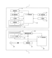
図2は、ガスコンロ1及びオーブン調理器2の構成を示すブロック図である。ガスコンロ1は、器具全体の動作を制御する制御部であるコンロ制御回路100と、オーブン調理器2や外部の通信装置3と信号を送受信する通信部である通信回路110と、所定レベルの作動電圧を生成してコンロ制御回路100に電力を供給する第1電源回路101と、第1電源供給部である一次電池102と、通信回路110用の作動電圧を生成して通信回路110に電力を供給する第2電源回路111と、第2電源供給部である二次電池112と、後述するオーブン調理器2の給電装置からワイヤレス給電により伝送される電力を受電して二次電池を充電する受電装置120とを有する。
Figure 2 is a block diagram showing the configuration of the
コンロ制御回路100は、CPU、メモリ、各種インターフェース回路等により構成された電子回路ユニットである。また、コンロ制御回路100は、メモリに登録された制御用プログラムをCPUで実行することにより、コンロバーナ11やグリルバーナの点消火及び火力調整を制御するバーナ制御部、一次電池102の電池電圧を検知する一次電池電圧検知部、二次電池112の電池電圧を検知する二次電池電圧検知部、受電装置120を制御して二次電池112を充電する充電制御部、通信回路110でのオーブン調理器2や外部の通信装置3との信号の送受信を制御する通信制御部として機能する。なお、コンロ制御回路100には、既述した電源スイッチ41、点消火操作子42,43、図示しない操作パネル、温度センサ、制御弁や、点火電極を駆動させるイグナイタ等が電気配線を介して接続されている。コンロ制御回路100には、温度センサの検知信号や、点消火操作子42,43及び操作パネルの操作信号、通信回路110により受信された信号が入力される。また、コンロ制御回路100から出力される制御信号によって、制御弁の開閉、イグナイタの駆動、受電装置120の動作、及び通信回路110による信号の送受信が制御される。
The
オーブン調理器2は、器具全体を制御するオーブン制御回路200と、所定レベルの作動電圧を生成して各回路に電力を供給する電源回路201と、ガスコンロ1や外部の通信装置3と信号を送受信する機器側通信回路202と、受電装置120にワイヤレス給電により電力を伝送する給電装置220とを有し、電源回路201は商用電源230と接続されている。オーブン制御回路200は、CPU、メモリ、各種インターフェース回路等により構成された電子回路ユニットである。また、オーブン制御回路200は、メモリに登録された制御用プログラムをCPUで実行することにより、オーブンバーナの点消火及び火力調整を制御するバーナ制御部、給電装置220を制御してワイヤレス給電を行う給電制御部、機器側通信回路202でのガスコンロ1や外部の通信装置3との信号の送受信を制御する通信制御部として機能する。なお、オーブン制御回路200には、電源スイッチ22、設定スイッチ23、図示しない点火電極を駆動させるイグナイタ、循環ファン、制御弁、温度センサ等が電気配線を介して接続されている。オーブン制御回路200には、温度センサの検知信号や、設定スイッチ23の操作信号、機器側通信回路202からの信号が入力される。また、オーブン制御回路200から出力される制御信号によって、給電装置220の動作、制御弁の開閉、イグナイタの駆動、循環ファンの駆動、機器側通信回路202による信号の送受信が制御される。
The
給電装置220は、給電コイル221と、給電コイル221に高周波電流を供給するインバータ回路222とを有する。給電コイル221は、インバータ回路222から高周波電流が供給されることで高周波磁界を発生する。給電装置220は、オーブン本体内の上方に配置されている。受電装置120は、受電コイル121と、充電回路122とを有する。受電コイル121は、給電コイル221で発生する高周波磁界により電磁誘導で電力を受電し、充電回路122は、受電コイル121から入力する交流電流を直流に変換して二次電池112の充電を行う。受電装置120は、コンロ本体10内の下方に配置されている。また、給電装置220及び受電装置120はそれぞれ、ガスコンロ1とオーブン調理器2とが上下に並設されたときに給電コイル221と受電コイル121とが略対向するように設けられている。なお、本実施の形態では、ワイヤレス給電方式として電磁誘導方式が採用されているが、磁界共鳴方式や電界結合方式を採用してもよい。
The
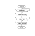
次に、図3を参照して、本実施の形態の加熱調理器における充電制御について説明する。なお、本実施の形態では、給電装置220は、コンロ制御回路100からの充電開始信号に応じて給電を開始させ、コンロ制御回路100からの充電終了信号に応じて給電を終了させるように構成されているが、所定のタイミング(例えば、所定時間ごと)で給電させるようにしてもよい。
Next, referring to FIG. 3, the charging control in the cooking device of this embodiment will be described. In this embodiment, the
コンロ制御回路100には二次電池112の電池電圧の検知信号が常時、入力されており、二次電池112の端子間の電池電圧が所定の充電開始電圧になると、ガスコンロ1からオーブン調理器2に充電開始信号を送信させる(ステップS1~S2)。図示しないが、充電開始信号を受信したオーブン制御回路200は、給電装置220を動作させて給電を開始させる。上記したように、給電コイル221に高周波電流が供給されると、ワイヤレス給電により給電装置220から受電装置120に電力が供給され、二次電池112が充電される。二次電池112の電池電圧が所定の充電終了電圧になると、ガスコンロ1は通信回路110からオーブン調理器2に充電終了信号を送信させ、充電を終了させる(ステップS3~S4)。
The
以上詳細に説明したように、本実施の形態によれば、ガスコンロ1は、コンロバーナ11やグリルバーナを動作させるコンロ制御回路100へ電力供給する一次電池102と、外部の通信端末3との通信を行う通信回路110に電力供給する二次電池112とを有するから、コンロ制御回路100への通電タイミングと通電回路110への通電タイミングとを非同期にさせる必要がなく、任意のタイミングで通電回路110へ電力を供給することができる。これにより、ガスコンロ1と外部の通信装置3との通信を円滑に行うことができるとともに、コンロバーナ11やグリルバーナをタイミングよく動作させることができる。また、常時、通信回路110へ電力供給できるため、ガスコンロ1の運転状態を24時間監視することもできる。また、電圧低下の大きな通電回路110への通電をコンロ制御回路100に電力を供給する一次電池102とは異なる二次電池112のみから行うことができるため、一次電池102の消耗も低減することができる。
As described above in detail, according to this embodiment, the
また、上記実施の形態によれば、ガスコンロ1の下方に隣接して配置されるオーブン調理器2等の商用電源230から電力が供給される外部機器に給電装置220が設けられているから、商用電源230から給電装置220に電力を供給するために長い電源線を設ける必要がない。
In addition, according to the above embodiment, the
また、上記実施の形態によれば、第2電源供給部は二次電池112を有し、給電装置220からのワイヤレス給電により二次電池112が充電されるから、オーブン調理器2に設けられている給電装置220とガスコンロ1に設けられている二次電池112とを電源線で接続する必要がない。これにより、ガスコンロ1の設置作業が簡易となる。
In addition, according to the above embodiment, the second power supply unit has a
また、上記実施の形態によれば、第2電源供給部である二次電池112の電池電圧が所定の充電開始電圧まで低下すると、外部機器のオーブン調理器2と通信して、給電装置220からのワイヤレス給電により二次電池112への充電を自動で開始させるから、常時、給電装置220へ電力を供給させる必要がない。これにより、通信回路110を動作させるための電池電圧を確保しつつ、効率的に二次電池112の充電を行うことができる。
In addition, according to the above embodiment, when the battery voltage of the
(その他の実施の形態)
(1)上記実施の形態では、外部機器に設けられた給電装置によって充電される二次電池が第2電源供給部として適用されている。しかしながら、二次電池を用いることなく、外部機器に設けられた給電装置から給電される受電回路を有する受電装置を設けて、受電回路から通信回路に電力を供給してもよい。
Other Embodiments
(1) In the above embodiment, a secondary battery charged by a power supply device provided in the external device is used as the second power supply unit. However, instead of using a secondary battery, a power receiving device having a power receiving circuit that receives power from a power supply device provided in the external device may be provided, and power may be supplied from the power receiving circuit to a communication circuit.
(2)上記実施の形態では、第1電源供給部として一次電池が使用されている。しかしながら、第1電源供給部として二次電池を用いてもよい。 (2) In the above embodiment, a primary battery is used as the first power supply unit. However, a secondary battery may also be used as the first power supply unit.
(3)上記実施の形態では、ガスコンロの下方に設けられるオーブン調理器に給電装置が設けられている。しかしながら、第2電源供給部に給電または充電する給電装置を設けることができる外部機器であれば、特に限定されない。例えば、食洗機等の他の電気機器に給電装置を設けてもよいし、無線通信方式の中継器や携帯型端末に給電装置を設けてもよい。商用電源により電力供給される中継器に給電装置を設けることにより、加熱調理器と中継器との通信を近距離通信(例えば、Bluetooth(登録商標))で行い、中継器と外部の通信装置との通信を中距離通信(例えば、Wi-Fi(登録商標))で行うことができるため、第2電源供給部に二次電池を使用する場合の充電回数を削減して、電池寿命を延ばすことができる。 (3) In the above embodiment, the power supply device is provided in the oven cooking device installed below the gas stove. However, there is no particular limitation as long as the external device can be provided with a power supply device that supplies power or charges the second power supply unit. For example, the power supply device may be provided in another electrical appliance such as a dishwasher, or in a wireless communication repeater or a portable terminal. By providing a power supply device in a repeater that receives power from a commercial power source, communication between the cooking device and the repeater can be performed by short-range communication (e.g., Bluetooth (registered trademark)) and communication between the repeater and an external communication device can be performed by medium-range communication (e.g., Wi-Fi (registered trademark)). This reduces the number of times a secondary battery is charged when used in the second power supply unit, and extends the battery life.
(4)上記実施の形態では、ガスコンロについて説明した。しかしながら、例えば、電気コンロ等の他の加熱調理器にも適用することができる。 (4) In the above embodiment, a gas stove was described. However, the invention can also be applied to other heating cookers, such as electric stoves.
1 ガスコンロ
11 コンロバーナ
100 コンロ制御回路
102 一次電池
110 通信回路
112 二次電池
2 オーブン調理器
220 給電装置
Claims (3)
外部の通信装置と通信する通信部と、
加熱部の動作を制御する制御部と、
前記制御部に電力を供給する第1電源供給部と、
前記通信部に電力を供給する第2電源供給部と、を有する加熱調理器であって、
前記第1電源供給部は、電池であり、
前記第2電源供給部は、前記加熱調理器とは異なる前記加熱調理器の外部に配設された外部機器に設けられ、商用電源で駆動する給電装置からのワイヤレス給電によって給電または充電が行われるように構成されている加熱調理器。 A heating unit for heating the food to be cooked;
A communication unit that communicates with an external communication device;
A control unit that controls the operation of the heating unit;
a first power supply unit that supplies power to the control unit;
A cooking device having a second power supply unit that supplies power to the communication unit,
the first power supply unit is a battery,
The second power supply unit is provided in an external device arranged outside the heating cooker and different from the heating cooker, and is configured to be powered or charged by wireless power supply from a power supply device powered by a commercial power source.
前記外部機器は、前記通信部と無線通信する中継器を有する加熱調理器。 The cooking device according to claim 1,
The external device is a cooking appliance having a repeater that wirelessly communicates with the communication unit.
前記第2電源供給部は、前記給電装置によって充電される二次電池であり、
前記制御部は、前記二次電池の電池電圧を検知する電圧検知部を有しており、
前記外部機器は、前記通信部と通信する機器側通信部を有し、
前記電圧検知部で前記二次電池の電池電圧が所定電圧まで低下したことが検知されると、前記加熱調理器は前記外部機器と通信して、前記給電装置からの前記ワイヤレス給電によって前記第2電源供給部への充電を開始させるように構成されている加熱調理器。 The cooking device according to claim 1 or 2,
the second power supply unit is a secondary battery that is charged by the power supply device,
the control unit has a voltage detection unit that detects a battery voltage of the secondary battery,
the external device has a device-side communication unit that communicates with the communication unit,
A heating cooker configured to communicate with the external device and start charging the second power supply unit via the wireless power supply from the power supply device when the voltage detection unit detects that the battery voltage of the secondary battery has dropped to a predetermined voltage.
Priority Applications (1)
| Application Number | Priority Date | Filing Date | Title |
|---|---|---|---|
| JP2020139734A JP7561540B2 (en) | 2020-08-21 | 2020-08-21 | Cooking equipment |
Applications Claiming Priority (1)
| Application Number | Priority Date | Filing Date | Title |
|---|---|---|---|
| JP2020139734A JP7561540B2 (en) | 2020-08-21 | 2020-08-21 | Cooking equipment |
Publications (2)
| Publication Number | Publication Date |
|---|---|
| JP2022035418A JP2022035418A (en) | 2022-03-04 |
| JP7561540B2 true JP7561540B2 (en) | 2024-10-04 |
Family
ID=80443337
Family Applications (1)
| Application Number | Title | Priority Date | Filing Date |
|---|---|---|---|
| JP2020139734A Active JP7561540B2 (en) | 2020-08-21 | 2020-08-21 | Cooking equipment |
Country Status (1)
| Country | Link |
|---|---|
| JP (1) | JP7561540B2 (en) |
Citations (3)
| Publication number | Priority date | Publication date | Assignee | Title |
|---|---|---|---|---|
| WO2017064803A1 (en) | 2015-10-16 | 2017-04-20 | 三菱電機株式会社 | Heating and cooking system, induction heating cooker, and electric apparatus |
| JP2017116161A (en) | 2015-12-22 | 2017-06-29 | リンナイ株式会社 | Cooking system |
| JP2020120166A (en) | 2019-01-18 | 2020-08-06 | リンナイ株式会社 | Device cooperation system and program |
Family Cites Families (5)
| Publication number | Priority date | Publication date | Assignee | Title |
|---|---|---|---|---|
| JP3317325B2 (en) * | 1995-11-09 | 2002-08-26 | リンナイ株式会社 | Gas combustion equipment |
| JPH1066274A (en) * | 1996-08-12 | 1998-03-06 | Nec Shizuoka Ltd | Power circuit for electronic equipment |
| JP6123586B2 (en) * | 2013-09-03 | 2017-05-10 | 三菱電機株式会社 | Cooker |
| JP6861489B2 (en) * | 2016-08-24 | 2021-04-21 | 三菱電機株式会社 | Cooker |
| JP6861607B2 (en) * | 2017-10-17 | 2021-04-21 | 大阪瓦斯株式会社 | Stove and watching system |
-
2020
- 2020-08-21 JP JP2020139734A patent/JP7561540B2/en active Active
Patent Citations (3)
| Publication number | Priority date | Publication date | Assignee | Title |
|---|---|---|---|---|
| WO2017064803A1 (en) | 2015-10-16 | 2017-04-20 | 三菱電機株式会社 | Heating and cooking system, induction heating cooker, and electric apparatus |
| JP2017116161A (en) | 2015-12-22 | 2017-06-29 | リンナイ株式会社 | Cooking system |
| JP2020120166A (en) | 2019-01-18 | 2020-08-06 | リンナイ株式会社 | Device cooperation system and program |
Also Published As
| Publication number | Publication date |
|---|---|
| JP2022035418A (en) | 2022-03-04 |
Similar Documents
| Publication | Publication Date | Title |
|---|---|---|
| JP6822803B2 (en) | Cooker | |
| EP4382810A2 (en) | Cook top, range hood and control methods thereof | |
| KR102668465B1 (en) | communications system | |
| KR20170078301A (en) | Terminal, cooking apparatus to communicate with the same and method of cooking apparatus | |
| CN105708305B (en) | Device for cooking and its control method | |
| JP7465626B2 (en) | Communication system and program | |
| JP2013158390A (en) | Electric rice cooker | |
| JP7561540B2 (en) | Cooking equipment | |
| JP2019192421A (en) | Induction heating cooker and induction heating cooker system | |
| JP7178274B2 (en) | Equipment linkage system and program | |
| KR20150022393A (en) | Cooking appliance | |
| JP7086447B2 (en) | Communications system | |
| JP6986484B2 (en) | Information notification system for cooking utensils | |
| JP4922809B2 (en) | Cooker | |
| JP5877037B2 (en) | Heating cooker power supply system | |
| JP2021148413A (en) | Heating cooker | |
| JP2020190357A (en) | Gas cooking stove | |
| US20250129943A1 (en) | Access control mode for an oven appliance | |
| JP2007051806A (en) | Cooker | |
| US20240172891A1 (en) | Methods and apparatus for high-heat cooking | |
| JP5118378B2 (en) | Cooker | |
| JP7246276B2 (en) | Combustion device communication system and combustion device | |
| CN118242671A (en) | Cooking Machines | |
| CN118242672A (en) | Cooking System | |
| JP2023070343A (en) | Heating cooking system and application program |
Legal Events
| Date | Code | Title | Description |
|---|---|---|---|
| A621 | Written request for application examination |
Free format text: JAPANESE INTERMEDIATE CODE: A621 Effective date: 20230616 |
|
| A977 | Report on retrieval |
Free format text: JAPANESE INTERMEDIATE CODE: A971007 Effective date: 20231120 |
|
| A131 | Notification of reasons for refusal |
Free format text: JAPANESE INTERMEDIATE CODE: A131 Effective date: 20240109 |
|
| A521 | Request for written amendment filed |
Free format text: JAPANESE INTERMEDIATE CODE: A523 Effective date: 20240229 |
|
| A131 | Notification of reasons for refusal |
Free format text: JAPANESE INTERMEDIATE CODE: A131 Effective date: 20240611 |
|
| A521 | Request for written amendment filed |
Free format text: JAPANESE INTERMEDIATE CODE: A523 Effective date: 20240731 |
|
| TRDD | Decision of grant or rejection written | ||
| A01 | Written decision to grant a patent or to grant a registration (utility model) |
Free format text: JAPANESE INTERMEDIATE CODE: A01 Effective date: 20240903 |
|
| A61 | First payment of annual fees (during grant procedure) |
Free format text: JAPANESE INTERMEDIATE CODE: A61 Effective date: 20240924 |
|
| R150 | Certificate of patent or registration of utility model |
Ref document number: 7561540 Country of ref document: JP Free format text: JAPANESE INTERMEDIATE CODE: R150 |