JP7561536B2 - Automated guided vehicles - Google Patents
Automated guided vehicles Download PDFInfo
- Publication number
- JP7561536B2 JP7561536B2 JP2020131823A JP2020131823A JP7561536B2 JP 7561536 B2 JP7561536 B2 JP 7561536B2 JP 2020131823 A JP2020131823 A JP 2020131823A JP 2020131823 A JP2020131823 A JP 2020131823A JP 7561536 B2 JP7561536 B2 JP 7561536B2
- Authority
- JP
- Japan
- Prior art keywords
- pallet
- legs
- guided vehicle
- automated guided
- center line
- Prior art date
- Legal status (The legal status is an assumption and is not a legal conclusion. Google has not performed a legal analysis and makes no representation as to the accuracy of the status listed.)
- Active
Links
- 238000001514 detection method Methods 0.000 claims description 40
- 238000004364 calculation method Methods 0.000 claims description 28
- 238000005259 measurement Methods 0.000 claims description 22
- 238000013459 approach Methods 0.000 claims description 12
- 238000012935 Averaging Methods 0.000 claims description 8
- 230000032258 transport Effects 0.000 claims description 3
- 238000000034 method Methods 0.000 description 117
- 230000008569 process Effects 0.000 description 110
- 230000000694 effects Effects 0.000 description 13
- 238000012545 processing Methods 0.000 description 13
- 238000010586 diagram Methods 0.000 description 10
- 239000003550 marker Substances 0.000 description 4
- 230000008859 change Effects 0.000 description 2
- 238000004891 communication Methods 0.000 description 2
- 230000002159 abnormal effect Effects 0.000 description 1
- 230000005856 abnormality Effects 0.000 description 1
- 238000006243 chemical reaction Methods 0.000 description 1
- 230000001678 irradiating effect Effects 0.000 description 1
- 238000012986 modification Methods 0.000 description 1
- 230000004048 modification Effects 0.000 description 1
- 230000003287 optical effect Effects 0.000 description 1
- 239000004065 semiconductor Substances 0.000 description 1
Images


Landscapes
- Control Of Position, Course, Altitude, Or Attitude Of Moving Bodies (AREA)
Description
本発明は、無人搬送車に関するものである。 The present invention relates to an automated guided vehicle.
特許文献1には、重量物が載置される架台21の下部両側に平板状の脚部22a,22bが一体に形成されたパレット20に進入し、荷台にパレット20を積載して搬送する無人搬送車10が開示されている。無人搬送車10の荷台の前後には、パレット20の架台21の裏面に貼着されたパレットガイド26を検出するパレットガイドセンサ12が設けられ、無人搬送車10の荷台の両側端には、パレット20の脚部22a,22bとの距離を検出するパレット側面ガイドセンサ15が設けられる。
無人搬送車10がパレット20に進入する場合に、パレットガイドセンサ12でパレットガイド26を検出し、パレット側面ガイドセンサ15で脚部22a,22bとの距離を検出することで、無人搬送車10とパレット20との位置関係を把握し、無人搬送車10の中心線とパレット20の中心線とが一致するように無人搬送車10を操舵する。これにより、作業員が無人搬送車10を操舵することなく、無人搬送車10をパレット20へ正確に進入させることができる。
When the automated guided
しかし特許文献1では、パレット20の全てにパレットガイド26を設け、無人搬送車10にパレットガイドセンサ12を設ける必要がある。従って、これらを設置するための手間およびコストが増大してしまう。また、パレット20を軽量にするため、パレット20の脚部22a,22bを平板状ではなく、トラス状や格子状等にして複数設けることが考えられる。このような場合、パレット側面ガイドセンサ15は、無人搬送車10のパレット20への進入と共に、距離の検出および非検出が繰り返され、脚部22a,22bとの距離を継続して検出することができないという問題点があった。
However, in
本発明は、上述した問題点を解決するためになされたものであり、パレットの脚が複数形成された場合でも、低コストかつ正確にパレットに進入できる無人搬送車を提供することを目的としている。 The present invention was made to solve the above-mentioned problems, and aims to provide an automated guided vehicle that can enter a pallet at low cost and accurately, even when the pallet has multiple legs.
この目的を達成するために本発明の無人搬送車は、両側部にそれぞれ複数設けられた脚と当該脚によって支持される台部とを有するパレットの前記台部の下方へ進入し、その台部の下方において荷台を上昇させることにより前記パレットを積載し、搬送するものであって、周囲の物体との距離および方向を測定するセンサであって、前記パレットへの進入方向側に設けられた進入センサと、周囲の物体との距離および方向を測定するセンサであって、前記進入方向における側方側に設けられた側方センサと、前記無人搬送車が前記パレットへ進入し又は前記パレットから離脱する場合、前記側方センサが前記パレットの外部に位置する際には前記進入センサによる測定データによって前記パレットの脚を検出し、前記側方センサが前記パレットの内部に位置する際には前記側方センサによる測定データによって前記パレットの脚を検出する脚検出手段と、その脚検出手段で検出されたパレットの脚から、前記パレットの両脚間の中心線を算出する中心線算出手段と、その中心線算出手段で算出されたパレットの両脚間の中心線と、前記無人搬送車の中心線とのズレ量を小さくするような前記無人搬送車の操舵角を算出する操舵角算出手段とを備えている。 In order to achieve this object, the automated guided vehicle of the present invention enters beneath a platform of a pallet having a platform supported by a plurality of legs provided on both sides thereof, and loads and transports the pallet by raising a loading platform beneath the platform, and includes an approach sensor that measures the distance and direction to surrounding objects and is provided on the approach direction side of the pallet, a lateral sensor that measures the distance and direction to surrounding objects and is provided on a lateral side in the approach direction, and a sensor that measures the distance and direction to surrounding objects and is provided on a lateral side in the approach direction when the automated guided vehicle enters the pallet or leaves the pallet. In this case, the system is equipped with leg detection means which detects the legs of the pallet from measurement data by the entry sensor when the side sensor is located outside the pallet, and detects the legs of the pallet from measurement data by the side sensor when the side sensor is located inside the pallet , center line calculation means which calculates a center line between both legs of the pallet from the legs of the pallet detected by the leg detection means, and steering angle calculation means which calculates a steering angle of the unmanned guided vehicle so as to reduce the amount of deviation between the center line between both legs of the pallet calculated by the center line calculation means and the center line of the unmanned guided vehicle.
請求項1記載の無人搬送車によれば、無人搬送車がパレットの下方へ進入し又はパレットから離脱する場合、進入センサ又は側方センサで測定された測定データからパレットの脚が検出され、検出されたパレットの脚に基づいて無人搬送車の操舵角を算出される。これにより、無人搬送車をパレットに進入させ、又はパレットから離脱させる際の位置制御のためにパレットにガイド等を設け、無人搬送車にそのガイド等を読み取るセンサを設ける必要がないので、無人搬送車およびパレットのコストを低減できるという効果がある。
According to the automated guided vehicle described in
ここで進入センサ及び側方センサは、周囲の物体との距離および方向を測定するので、パレットの脚が複数設けられ、パレットの脚と脚との間に間隔がある場合でも、進入センサ及び側方センサの検出範囲におけるパレットの脚の位置を継続して検出できる。これにより、無人搬送車を正確にパレットへ進入させ、またはパレットから離脱させることができるという効果がある。 The entry sensor and side sensor measure the distance and direction to surrounding objects, so even if the pallet has multiple legs and there is a gap between each pair of legs, the position of the pallet legs within the detection range of the entry sensor and side sensor can be continuously detected. This has the effect of allowing the automated guided vehicle to accurately enter or leave the pallet.
また、側方センサがパレットの外部に位置する場合は進入センサによる測定データによってパレットの脚が検出され、側方センサがパレットの内部に位置する場合は側方センサによる測定データによってパレットの脚が検出される。側方センサがパレットの外部に位置する場合は、進入センサはパレットの脚と対向するので、パレットに設けられる脚を多数検出できる。このように進入センサによって多数検出されたパレットの脚に基づくことで、パレットの両脚間の位置をより正確に算出できるという効果がある。 Furthermore, when the side sensor is located outside the pallet, the legs of the pallet are detected by the measurement data from the entry sensor, and when the side sensor is located inside the pallet, the legs of the pallet are detected by the measurement data from the side sensor. When the side sensor is located outside the pallet, the entry sensor faces the legs of the pallet, so a large number of legs on the pallet can be detected. In this way, based on the large number of pallet legs detected by the entry sensor, the position between both legs of the pallet can be calculated more accurately.
その一方で、側方センサがパレットの内部に位置する場合は、パレットの脚が側方センサと対向するので、かかる場合は側方センサによってパレットの脚が多数検出される。このように側方センサによって多数検出されたパレットの脚に基づくことで、無人搬送車がパレット内に位置する場合であっても、パレットの両脚間の位置をより正確に算出できるという効果がある。 On the other hand, when the side sensor is located inside the pallet, the legs of the pallet face the side sensor, and in such a case, a large number of the pallet legs are detected by the side sensor. In this way, based on the large number of pallet legs detected by the side sensor, it is possible to more accurately calculate the position between the two legs of the pallet, even when the automated guided vehicle is located inside the pallet.
更に検出されたパレットの脚から算出されたパレットの両脚間の中心線と、無人搬送車の中心線とのズレ量を小さくするような無人搬送車の操舵角が算出される。これにより、無人搬送車をパレットの中心に沿って走行させることができるので、無人搬送車1とパレット、特にパレットの脚との接触を抑制できるという効果がある。
Furthermore, a steering angle of the automated guided vehicle is calculated to reduce the amount of deviation between the center line of the automated guided vehicle and the center line of the pallet calculated from the detected pallet legs. This allows the automated guided vehicle to travel along the center of the pallet, which has the effect of suppressing contact between the automated guided
請求項2記載の無人搬送車によれば、請求項1記載の無人搬送車の奏する効果に加え、次の効果を奏する。パレットの脚における最も内側の位置に基づいて、パレットの両脚間の中心線が算出される。即ち中心線がパレットの両脚間における最も狭い位置に基づいて算出されるので、無人搬送車とパレットの脚との接触を抑制できるという効果がある。
According to the automated guided vehicle of
請求項3記載の無人搬送車によれば、請求項1又は2に記載の無人搬送車の奏する効果に加え、次の効果を奏する。パレットの脚の左右のペア毎にそれらの中間点が算出され、算出された中間点に基づいてパレットの両脚間の中心線が算出される。かかる中心線に基づいて無人搬送車の操舵角を算出することで、無人搬送車は、パレットの脚の左右のペアの中間点に沿って走行できるので、無人搬送車とパレットの脚との接触を好適に抑制できるという効果がある。
According to the automated guided vehicle of
請求項4記載の無人搬送車によれば、請求項3記載の無人搬送車の奏する効果に加え、次の効果を奏する。パレットの脚の左右のペアの中間点であって、無人搬送車寄りの中間点と、それ以外の中間点とを結ぶ複数の直線が算出され、算出された直線を平均することで、パレットの両脚間の中心線が算出される。即ち中心線が、最も無人搬送車に近い中間点、即ち無人搬送車が通過中または通過する直前のパレットの脚の中間点と、それ以外のパレットの脚の中間点とから算出されるので、かかる中心線に基づいて操舵角を算出することで、操舵角の変化を小さく留めながらも無人搬送車とパレットの脚との接触をより好適に抑制できるという効果がある。
According to the automated guided vehicle of claim 4 , in addition to the effects of the automated guided vehicle of
請求項5記載の無人搬送車によれば、請求項1から4のいずれかに記載の無人搬送車の奏する効果に加え、次の効果を奏する。側方センサの正面を通過するパレットの脚の数が計測され、計測されたパレットの脚の数から、パレット内における無人搬送車の位置が検出される。これにより、パレットに無人搬送車の位置を表すマーカ等を設け、無人搬送車にそのマーカ等を検出するセンサ等を設けることなく、パレット内における無人搬送車の位置が把握できるので、無人搬送車およびパレットのコストを低減できるという効果がある。
The automated guided vehicle according to claim 5 has the following effect in addition to the effect of the automated guided vehicle according to any one of
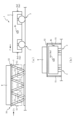
以下、本発明の好ましい実施形態について、添付図面を参照して説明する。まず、図1を参照して、本実施形態における無人搬送車1の構成を説明する。図1(a)は、無人搬送車1及びパレット50を表す図であり、図1(b)は、矢印Ib方向における無人搬送車1及びパレット50を表す図である。図1,2における矢印Fの方向は、無人搬送車1の進行方向を表す。本実施形態では、無人搬送車1の長手方向を「前後」とし、図1(a)の左側を仮に前方とする。
A preferred embodiment of the present invention will now be described with reference to the accompanying drawings. First, the configuration of an automated guided
無人搬送車1は、積載物Wを搭載したパレット50を積載して自動走行する搬送車であり、車体2と、走行装置3と、進入センサ4aと、側方センサ4bとを備える。走行装置3は、無人搬送車1を走行させる装置であり、無人搬送車1の上面視における4隅にそれぞれ配設される。
The automated guided
進入センサ4aは、周囲の物体との距離および方向を測定するセンサであり、無人搬送車1の前後に設けられる。本実施形態では、前後の進入センサ4aのうち、パレット50への進入方向側の進入センサ4aを「進入センサ4a1」とし、パレット50への進入方向と逆側の進入センサ4aを「進入センサ4a2」とする。側方センサ4bは、周囲の物体との距離および方向を測定するセンサであり、無人搬送車1の側方の一側(本実施形態では図1(a)の進行方向の左側)に設けられる。進入センサ4a,側方センサ4bは、その周囲にレーザ光L(図2参照)を照射することで、進入センサ4a,側方センサ4bと物体との距離および方向が測定される。なお、進入センサ4aを設ける位置は、無人搬送車1の前後両方に限らず、無人搬送車1の前側のみでも良いし、後側のみでも良い。また側方センサ4bを設ける位置は、進行方向の左側に限らず、右側でも良いし、無人搬送車1の両側方に設けても良い。
The
その無人搬送車1に積載されるパレット50は、脚51と、台部52とを有する。脚51は、パレット50の両側部にそれぞれ複数設けられる柱状の部材である。脚51はパレット50の両側部に6本ずつ設けられ、6本の脚51がトラス構造となるように接合されて構成される。台部52は、両側の脚51の上部に接合され、積載物Wを搭載するための平板状の部材である。なお、脚51の脚の数は6本に限らず、台部52の全長や搭載する積載物Wの質量に応じて6本以上でも良いし、6本以下でも良い。
The
無人搬送車1はパレット50を積載する場合は、その車高を下げて台部52の下方に進入する。パレット50における所定の位置まで進入した後、走行を停止し、無人搬送車1の車高を上げることで、車体2の上面に形成される荷台にパレット50が積載される。一方で、積載したパレット50を無人搬送車1から降ろし、パレット50から離脱させる場合は、無人搬送車1の車高を下げ、車体2の荷台からパレット50を降ろし、車高を下げた状態で、パレット50に進入してきた方向の逆方向に走行することで、無人搬送車1がパレット50から離脱される。
When loading a
本実施形態では、無人搬送車1のパレット50への進入およびパレットからの離脱において、進入センサ4a及び側方センサ4bで測定された周囲の物体との距離および方向による測定データからパレット50の脚51を検出し、検出された脚51の位置に基づいて、無人搬送車1を操舵する。図2,3を用いて、進入センサ4a及び側方センサ4bによる脚51の検出および無人搬送車1の操舵方式を説明する。
In this embodiment, when the automated guided
図2(a)は、無人搬送車1がパレット50に進入しようとしている状態を表す図であり、図2(b)は、無人搬送車1がパレット50に進入した状態を表す図である。図2においては、説明のため、パレット50における台部52の図示を省略して表し、脚51において、進入センサ4a及び側方センサ4bによって検出されている部分を太線で表し、検出されていない部分を破線で表す。
Figure 2(a) shows the state in which the automated guided
まず、図2(a)に示す通り、無人搬送車1がパレット50の外部に位置する場合は、パレット50と対向する進入センサ4a1によって脚51が検出される。かかるパレット50と対向する進入センサ4a1によって、パレット50の脚51が多数検出されるので、脚51の位置を的確に検出できる。
First, as shown in FIG. 2(a), when the automated guided
本実施形態では、パレット50の脚51等の位置を、無人搬送車1の上面視における中央を基準位置(即ち原点(0,0))として、無人搬送車1の前後方向および左右方向を座標軸とした場合の「相対位置」で表現される。進入センサ4a及び側方センサ4bで測定された測定データの相対位置への変換は、公知技術のためその説明は省略する。なお、基準位置は、無人搬送車1の上面視における中央に限らず、無人搬送車1の前端における中央等、無人搬送車1の他の部分でも良い。また、パレット50の脚51等の位置を相対位置で表現するものに限らず、特定の地点を基準位置とした「絶対位置」で表現しても良い。
In this embodiment, the positions of the
パレット50の脚51が検出された場合、検出された脚51から、両側左右の脚51のペアが形成される。具体的には、検出された脚51の中で、パレット50の長さ方向における位置が略同一の脚51同士が、脚51のペアとしてグルーピングされる。その脚51のペアの最も内側の位置PpL及び位置PpRが取得され、これら位置PpL及び位置PpRを結ぶ線の中間点Ccに基づいて両側の脚51の中心線Pcが算出される。そして、その中心線Pcに基づいて、無人搬送車1が操舵される。なお、操舵角θvの具体的な操舵方式は図3で後述する。
When the
一方で、無人搬送車1がパレット50の内部に位置する場合は、図2(b)に示す通り、側方センサ4bを用いて脚51が検出される。無人搬送車1がパレット50の内部に位置する場合は、側方センサ4bが脚51と対向するので、側方センサ4bによって多数の脚51が検出される。これにより、脚51の位置を的確に検出できる。
On the other hand, when the automated guided
側方センサ4bからは、両側の脚51のうちの片方の脚51のみが検出されるので、検出された片方の脚51から、図2(a)同様の中心線Pcが算出される。具体的には、側方センサ4bから検出された片方の脚51の位置を、後述するパレットデータ11bに記憶される両側の脚51間の距離Lpの半分である距離Lp/2だけ、両側の脚51の内側へ移動(オフセット)することでそれらの中間点Ccが取得され、取得された中間点Ccに基づいて中心線Pcが算出される。
Since only one of the
本実施形態において、パレット50内における無人搬送車1の停止位置、即ち無人搬送車1の車体2にパレット50を積載させる位置は、脚51のうち、無人搬送車1の進入方向側から3本目の脚51aと4本目の脚51bとの中間の位置(即ち図2(b)における無人搬送車1の位置)とされる。そのため本実施形態においては、パレット50内における無人搬送車1の位置を側方センサ4bの真正面を通過した脚51の数(図4で後述する通過脚位置メモリ12h)から判断する。
In this embodiment, the stopping position of the automated guided
具体的には、無人搬送車1がパレット50に進入する場合は、パレット50の進入前の脚51の数を0本として、側方センサ4bの真正面を脚51が通過するごとに1本ずつ加算していく。即ち無人搬送車1がパレット50に進入する場合は、パレット50内に進入してから通過した脚51の数に基づき、パレット50内における無人搬送車1の位置が判断される。
Specifically, when the automated guided
一方で無人搬送車1がパレット50から離脱する場合は、パレット50内における停止位置(即ち脚51aと脚51bとの間)の脚51の数である3本から、側方センサ4bの真正面を脚51が通過するごとに1本ずつ減算していく。即ち無人搬送車1がパレット50から離脱する場合は、パレット50から離脱するまでの脚51の数に基づき、パレット50内における無人搬送車1の位置が判断される。
On the other hand, when the automated guided
このように、側方センサ4bを通過した脚51の数に基づいて、パレット50内の位置を判断する。これにより、パレット50内に無人搬送車1の位置を表すマーカ等を設け、無人搬送車1にそのマーカ等を検出するセンサ等を設けることなく、無人搬送車1のパレット50内の位置を容易に判断できる。よって、無人搬送車1及びパレット50のコストを低減できる。
In this way, the position within the
次に図3を参照して、図2(a),(b)で説明したパレット50の中心線Pcから無人搬送車1の操舵方式を説明する。
Next, referring to Figure 3, we will explain the steering method of the automated guided
図3は、無人搬送車1の操舵制御を説明する図である。無人搬送車1の前端部および後端部には、無人搬送車の中心線Lcとパレット50の中心線Pcとのズレ量を検出する仮想の検出エリアDpがそれぞれ設けられる。各走行装置3の操舵角θvは、前後の検出エリアDpで検出された、無人搬送車の中心線Lcとパレット50の中心線Pcとのズレ量df,drに基づいて算出される。
Figure 3 is a diagram explaining the steering control of the automated guided
具体的には、まず中心線Lc上であって、前側の検出エリアDpの上面視における中央位置から、後方に所定の距離Lipを移動した位置に仮想原点Cfを設定し、後側の検出エリアDpの上面視における中央位置から、後方に距離Lipを移動した位置に仮想原点Crを設定する。そして、前側の検出エリアDpにおけるパレット50の中心線Pcの位置Gf、即ち中心線Lcとのズレ量dfに応じた位置と仮想原点Cfとを結ぶ線分に直交し、かつ車体2の後方側に向かう直線を引く。後側の検出エリアDpにおける中心線Pcの検出位置Gr、即ち中心線Lcとのズレ量drに応じた位置と仮想原点Crとを結ぶ線分に直交し、かつ車体2の前方側に向かう直線を引く。これらの直線の交点が旋回中心Cとされる。
Specifically, first, a virtual origin Cf is set on the center line Lc at a position that is a predetermined distance Lip rearward from the center position of the front detection area Dp in a top view, and a virtual origin Cr is set at a position that is a distance Lip rearward from the center position of the rear detection area Dp in a top view. Then, a straight line is drawn that is perpendicular to the line segment connecting the virtual origin Cf and the position Gf of the center line Pc of the
その旋回中心Cを中心とし、走行装置3の中心を通る、円弧状の旋回経路Rを生成する。その旋回経路Rにおける各走行装置3の中心における接線方向のうち、無人搬送車1の進行方向側の方向Vのなす角θvが、操舵角θvとされる。
A circular arc-shaped turning path R is generated that is centered on the turning center C and passes through the center of the traveling
なお図3では、無人搬送車1の上面視右上における走行装置3の操舵角θvのみを図示しているが、他の走行装置3に対する操舵角θvの算出方式も同様なので、図示は省略する。各走行装置3の向きがそれぞれに対して算出された操舵角θvと一致するように、各走行装置3が操舵制御される。
Note that FIG. 3 only illustrates the steering angle θv of the traveling
次に、図4を参照して、無人搬送車1の電気的構成について説明する。図4は、無人搬送車1の電気的構成を示すブロック図である。無人搬送車1は、CPU10と、フラッシュROM11と、RAM12とを備え、これらはバスライン13を介して、入出力ポート14にそれぞれ接続されている。入出力ポート14には、上述した進入センサ4a(進入センサ4a1,4a2)と、側方センサ4bと、走行装置3と、外部の機器と情報を送受信する通信装置15とがそれぞれ接続されている。なお、走行装置3は、無人搬送車1に複数配設されるが、図4においては、まとめて1つの走行装置3として表している。
Next, the electrical configuration of the automated guided
CPU10は、バスライン13及び入出力ポート14に接続された各部を制御する演算装置である。フラッシュROM11は、書き換え可能な不揮発性のメモリであり、制御プログラム11aと、パレットデータ11bと、停止速度ゲインデータ11cとが記憶される。制御プログラム11aは、CPU10に図5のパレット進入・離脱処理を実行させるプログラムである。
The
パレットデータ11bには、パレット50の各種情報、具体的には、パレット50の脚51間の距離Lpや、各脚51の位置と無人搬送車1の停止位置との距離や、パレット50の全長や全幅等が記憶される。停止速度ゲインデータ11cには、無人搬送車1がパレット50内を走行する際の、無人搬送車1とパレット50内における停止位置との距離(残距離)に応じた速度を算出するためのゲイン値が記憶される。無人搬送車1とパレット50の停止位置との距離に停止速度ゲインデータ11cに記憶されるゲイン値を乗じることで、無人搬送車1の位置に応じた速度が算出される。
The pallet data 11b stores various information about the
RAM12は、CPU10が制御プログラム11a等の実行時に各種のワークデータやフラグ等を書き換え可能に記憶するためのメモリであり、各走行装置3の操舵角θvが区別されて記憶される操舵角メモリ12aと、無人搬送車1の走行速度が記憶される速度メモリ12bと、進入センサ4aに基づいて算出された中心線Pcが記憶される前後中心線メモリ12cと、側方センサ4bに基づいて算出された中心線Pcが記憶される側方中心線メモリ12dと、操舵角θvの算出に用いられる中心線Pcが記憶される中心線メモリ12eと、進入センサ4aで検出されたパレット50の脚51のペア数が記憶される前後側ペア数メモリ12fと、側方センサ4bで検出されたパレット50の脚51の数が記憶された側方側脚数メモリ12gと、通過脚位置メモリ12hと、無人搬送車1の位置とパレット50内の無人搬送車1の停止位置との距離を記憶する残距離メモリ12iとが設けられる。
The
通過脚位置メモリ12hには、無人搬送車1のパレット50内の位置に応じたパレット50の脚51の数が記憶される。具体的に、通過脚位置メモリ12hには側方センサ4bの真正面を通過した脚51の数が記憶され、上記した通り、無人搬送車1がパレット50に進入する場合は、通過脚位置メモリ12hの初期値が0とされ、側方センサ4bの真正面を通過する度に通過脚位置メモリ12hに1が加算される。一方で、無人搬送車1がパレット50から離脱する場合は、通過脚位置メモリ12hの初期値がパレット50内の無人搬送車1の停止位置である3とされ、側方センサ4bの真正面を通過する度に通過脚位置メモリ12hから1が減算される。
The passing leg position memory 12h stores the number of
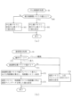
次に、図5~7を参照して、無人搬送車1のCPU10で実行される処理について説明する。図5は、パレット進入・離脱処理のフローチャートである。パレット進入・離脱処理は、上位プロコン(図示せず)から通信装置15を介して受信した無人搬送車1への動作モードが、パレット50への進入を指示する「パレット進入」、又はパレット50から離脱を指示する「パレット離脱」である場合に実行される処理である。
Next, the processing executed by the
パレット進入・離脱処理はまず、初期化処理を行う(S1)。S1の初期化処理では、特に、前後側ペア数メモリ12f及び側方側脚数メモリ12gに「0」が設定され、通過脚位置メモリ12hには、上記した通り、無人搬送車1をパレット50に進入させる場合には「0」が、パレット50から無人搬送車1を離脱させる場合には「3」がそれぞれ設定される。S1の初期化処理によって、その他のRAM12のメモリ値もそれぞれに応じた初期値が設定される。
The pallet entry/exit process begins with an initialization process (S1). In the initialization process of S1, in particular, "0" is set in the front and rear pair number memory 12f and the lateral
S1の処理の後、無人搬送車1の現在位置が停止位置に到達したかを確認する(S2)。S2の処理で確認される停止位置は、無人搬送車1をパレット50へ進入させる場合は、上記した停止位置、即ちパレット50における進入方向側から3本目の脚51aと4本目の脚51bとの中間の位置であり(図2(b)参照)、無人搬送車1をパレット50から離脱させる場合は上位プロコンで指定されたパレット50の外部における位置である。
After processing S1, it is confirmed whether the current position of the automated guided
S2の処理において、無人搬送車1の現在位置が停止位置に到達していない場合は(S2:No)、前後側検出処理(S3)を実行する。ここで図6(a)を参照して、前後側検出処理を説明する。
In the process of S2, if the current position of the automated guided
図6(a)は、前後側検出処理のフローチャートである。前後側検出処理は、進入センサ4aに基づいて、中心線Pc及びパレットの脚51のペア数を算出する処理である。前後側検出処理はまず、上位プロコンから指示された動作モードを確認する(S20)。
Figure 6 (a) is a flowchart of the front/rear side detection process. The front/rear side detection process is a process for calculating the center line Pc and the number of pairs of
S20の処理において、動作モードがパレット進入である場合は(S20:「パレット進入」)、前後の進入センサ4aのうち、測定データを測定するセンサとして無人搬送車1の前方の進入センサ4aが設定され(S21)、S20の処理において、動作モードがパレット離脱である場合は(S20:「パレット離脱」)、測定データを測定するセンサとして後方の進入センサ4aが設定される(S22)。以下、前後側検出処理において、S21,S22の処理で設定される進入センサ4aのことを「対象センサ」という。
In the process of S20, if the operating mode is pallet entry (S20: "pallet entry"), of the front and
即ちS21,S22の処理によって、無人搬送車1の前後の進入センサ4aのうち、パレット50の脚51と対向する進入センサ4aが「対象センサ」に設定される。パレット50への進入時においては、無人搬送車1の前後に設けられる進入センサ4aのうち、パレット50に近い進入センサ4aが対象センサに設定されるので、パレット50の脚51をより正確に検知できる。一方でパレット50からの離脱時においては、S22の処理で図2(a)における進入センサ4a1が対象センサに設定されることで、かかる進入センサ4a1では無人搬送車1の走行に応じて検出されるパレット50の脚51の数を徐々に増加させることができる。
That is, by the processing of S21 and S22, of the
S21,S22の処理の後、対象センサから測定データを取得し(S23)、取得された測定データから、上記したパレット50の脚51のペアを全て検出する(S24)。その後、S24の処理によって、パレット50の脚51のペアが検出されたかを確認する(S25)。
After the processes of S21 and S22, measurement data is acquired from the target sensor (S23), and all pairs of
S25の処理において、脚51のペアが検出された場合は(S25:Yes)、検出された各脚51のペアにおける、中間点Ccを取得する(S26)。具体的には、検出された各脚51のペアに該当する測定データを図2で上記した相対位置に変換した上で、脚51のペアのそれぞれにおいて、脚51のペア同士の最も内側の位置を結ぶ線の中間点Ccが取得される。
If a pair of
S26の処理の後、取得された各脚51のペアの中間点Ccから、パレット50の中心線Pcを算出し、前後中心線メモリ12cに保存する(S27)。具体的には、取得された脚51のペアの中間点Ccのうち、最も無人搬送車1に近い中間点Ccと、それ以外の中間点Ccとの直線を全て算出し、算出された直線を平均することで中心線Pcが算出され、前後中心線メモリ12cに保存される。
After the process of S26, the center line Pc of the
S27の処理の後、S25の処理で検出された脚51のペア数を取得し、前後側ペア数メモリ12fに保存する(S28)。
After processing in S27, the number of pairs of
S25の処理で脚51のペアが検出されなかった場合(S25:No)、又はS28の処理の後、前後側検出処理を終了する。
If a pair of
図5に戻る。S3の前後側検出処理の後、側方側検出処理(S4)を実行する。ここで、図6(b)を参照して、側方側検出処理を説明する。 Returning to FIG. 5, after the front/rear detection process in S3, the side detection process (S4) is executed. Now, the side detection process will be explained with reference to FIG. 6(b).
図6(b)は、側方側検出処理のフローチャートである。側方側検出処理は、側方センサ4bに基づいて、中心線Pcと側方センサ4bが通過した脚51の数とを算出する処理である。
Figure 6 (b) is a flowchart of the lateral detection process. The lateral detection process is a process for calculating the center line Pc and the number of
側方側検出処理はまず、側方センサ4bから測定データを取得する(S40)。S40の処理の後、取得した測定データからパレット50の脚51を全て検出する(S41)。S41の処理の後、脚51が検出されたかを確認する(S42)。
The lateral detection process first acquires measurement data from the
S42の処理において、脚51が検出された場合は(S42:Yes)、検出された各脚51から、パレット50の中間点Ccを算出する(S43)。具体的には、検出された各脚51に該当する測定データを図2で上記した相対位置に変換した上で、各脚51の最も内側、即ちパレット50の中心側の位置を取得し、その位置からパレットデータ11bに記憶されるパレット50の左右の脚51間の半分の距離Lp/2だけ、両側の脚51の内側へ移動した位置が、各脚51の中間点Ccに設定される。
In the process of S42, if a
S43の処理の後、S43の処理で算出された中間点Ccからパレット50の中心線Pcを算出し、側方中心線メモリ12dに保存する(S44)。具体的には、図6(a)のS27の処理と同様に、S43の処理で算出された中間点Ccのうち、最も無人搬送車1に近い中間点Ccと、それ以外の中間点Ccとの直線を全て算出し、算出された直線を平均することで中心線Pcが算出され、側方中心線メモリ12dに保存される。
After the process of S43, the center line Pc of the
S44の処理の後、S42の処理で検出された脚51の数を取得し、側方側脚数メモリ12gに保存する(S45)。S45の処理の後、S42の処理で検出された脚51のうち、側方センサ4bの真正面に位置する脚51が存在するかを確認する(S46)。具体的には、側方センサ4bで取得された測定データにおける側方センサ4bの真正面(0度)に該当する距離を確認し、脚51における最も進行方向側の位置が検出できた場合、例えば、側方センサ4bの真正面に該当する距離が10m以上から1m以下に変化した場合に、側方センサ4bの真正面に位置する脚51が存在すると判断される。S46の処理において、側方センサ4bの真正面に位置する脚51が存在する場合は(S46:Yes)、上記した上位プロコンから指示された動作モードを確認する(S47)。
After the process of S44, the number of
S47の処理において、動作モードがパレット進入である場合は(S47:「パレット進入」)、通過脚位置メモリ12hに1を加算し(S48)、動作モードがパレット離脱である場合は(S47:「パレット離脱」)、通過脚位置メモリ12hから1を減算する(S49)。 In the process of S47, if the operation mode is pallet entry (S47: "pallet entry"), 1 is added to the passing leg position memory 12h (S48), and if the operation mode is pallet departure (S47: "pallet departure"), 1 is subtracted from the passing leg position memory 12h (S49).
S42の処理において、脚51が検出されなかった場合(S42:No)、S46の処理において側方センサ4bの真正面に位置する脚51が存在しなかった場合(S46:No)、またはS48,S49の処理の後、側方側検出処理を終了する。
If a
図5に戻る。S4の側方側検出処理の後、前後側ペア数メモリ12fの脚51のペア数が2以上または側方側脚数メモリ12gの脚51の数が2以上かを確認する(S5)。S5の処理において、前後側ペア数メモリ12fの脚51のペア数が2以上または側方側脚数メモリ12gの脚51の数が2以上である場合は(S5:Yes)、進入センサ4a又は側方センサ4bによって脚51のペアが検出され、S3又はS4の処理によって中心線Pcが算出できたと判断できるので、かかる場合に中心線選択処理(S6)を実行する。ここで図7(a)を参照して、中心線選択処理を説明する。
Returning to FIG. 5, after the lateral detection process of S4, it is confirmed whether the number of pairs of
図7(a)は、中心線選択処理のフローチャートである。中心線選択処理は、側方側脚数メモリ12gの脚51の数に応じて、走行装置3の操舵角θvの算出に用いる中心線Pcを、前後中心線メモリ12cと側方中心線メモリ12dとのいずれかから選択する処理である。中心線選択処理は、まず、側方側脚数メモリ12gの脚51の数が2以上かを確認する(S60)。
Figure 7 (a) is a flowchart of the center line selection process. The center line selection process is a process for selecting the center line Pc used to calculate the steering angle θv of the traveling
S60の処理において、側方側脚数メモリ12gの脚51の数が2より小の場合は(S60:No)、中心線メモリ12eに前後中心線メモリ12cの値を設定し(S61)、一方で側方側脚数メモリ12gの脚51の数が2以上の場合は(S60:Yes)、中心線メモリ12eに側方中心線メモリ12dの値を設定する(S62)。
In the process of S60, if the number of
具体的に、S60の処理において、側方側脚数メモリ12gの脚51の数が2より小の場合は(S60:No)、S4の側方側検出処理(図6(b))によって側方センサ4bで検出された脚51の数が少ない一方で、S3の前後側検出処理(図6(a))によって進入センサ4aで多くの脚51のペアが検出された場合である。即ち無人搬送車1(特に側方センサ4b)がパレット50の進入する前の場合またはパレット50へ進入して間もない場合や、無人搬送車1がパレット50から離脱する直前の場合または離脱した後の場合である。
Specifically, in the process of S60, if the number of
かかる場合に、前方の進入センサ4aはパレット50の脚51と対向する一方で、側方センサ4bは、パレット50の脚51と対向しないので、前方の進入センサ4aで検出されるパレットの脚51の数は、側方センサ4bで検出される脚51の数よりも多く検出できる。よって、より多くのパレットの脚51から算出された、前方の進入センサ4aによる前後中心線メモリ12cを中心線メモリ12eに設定することで、中心線メモリ12eには多くのパレットの脚51から算出された、より正確な中心線Pcを設定できる。
In such a case, while the
一方で、S60の処理において、側方側脚数メモリ12gの脚51の数が2以上の場合は(S60:Yes)、S3の前後側検出処理によって進入センサ4aで検出された脚51のペアが少ない一方で、S4の側方側検出処理によって側方センサ4bで多くの脚51の数が検出された場合である。即ち無人搬送車1がパレット50に進入して、しばらく経った場合や、無人搬送車がパレット50から離脱し始めてから間もない状態で、無人搬送車1がパレット50内に位置する場合である。
On the other hand, in the process of S60, if the number of
かかる場合、前方の進入センサ4aと対向するパレット50の脚51が少ない一方で、側方センサ4bは、パレット50の脚51と対向するので、側方センサ4bによって多くの脚51が検出できる。よって、側方センサ4bによる側方中心線メモリ12dを中心線メモリ12eに設定することで、無人搬送車1がパレット50内を進行している場合でも、中心線メモリ12eには多くのパレットの脚51から算出された、より正確な中心線Pcを設定できる。
In such a case, while there are
S61又はS62の処理の後、中心線選択処理を終了する。 After processing S61 or S62, the center line selection process ends.
図5に戻る。S6の中心線選択処理の後、図3で説明した方式により、無人搬送車1の仮想原点Cf,Crと、中心線メモリの中心線Pcとのズレ量df,drとに基づいて、旋回中心Cを算出し(S7)、その旋回中心Cに基づいて各走行装置3の操舵角θvを算出し、操舵角メモリ12aに保存する(S8)。S8の処理の後、速度算出処理(S9)を実行する。ここで図7(b)を参照して、速度算出処理を説明する。
Return to FIG. 5. After the center line selection process of S6, the method described in FIG. 3 is used to calculate the turning center C based on the deviations df, dr between the virtual origins Cf, Cr of the automated guided
図7(b)は、速度算出処理のフローチャートである。速度算出処理は、無人搬送車1のパレット50内における位置に応じた無人搬送車1の走行速度を設定する処理である。速度算出処理はまず、上位プロコンから指示された動作モードを確認する(S70)。S70の処理において、動作モードがパレット進入である場合は(S70:「パレット進入」)、通過脚位置メモリ12hの脚51の数が3であるかを確認する(S71)。上記した通り、パレット50内における停止位置は、無人搬送車1の進入方向側から3本目の脚51aと4本目の脚51b(共に図2(b)参照)との中間の位置とされるので、S71の処理では、停止位置の手前の3本目の脚51aを通過したかが確認される。
Figure 7 (b) is a flow chart of the speed calculation process. The speed calculation process is a process for setting the travel speed of the automatic guided
S71の処理において、通過脚位置メモリ12hの脚51の数が3である場合(S71:Yes)、通過脚位置メモリ12hの脚51の数から、停止位置までの残距離を算出し、残距離メモリ12iに保存する(S72)。具体的には、パレットデータ11bには、パレット50の各脚51の位置から停止位置までの無人搬送車1の進行方向側の距離が記憶されているので、通過脚位置メモリ12hの脚51の数に該当する停止位置までの距離をパレットデータ11bから取得し、残距離メモリ12iに記憶する。この際、無人搬送車1が隣り合う脚51の中間に位置する場合は、直前に検出した脚51からの移動距離が、残距離メモリ12iから減算される。
In the process of S71, if the number of
S72の処理の後、速度メモリ12bに、残距離メモリ12iの残距離に停止速度ゲインデータ11cのゲイン値を乗じた速度を設定する(S73)。
After processing in S72, a speed is set in the speed memory 12b, which is the remaining distance in the remaining
即ち無人搬送車1がパレット50内に進入して停止する場合、無人搬送車1とパレット50内の停止位置との残距離が通過脚位置メモリ12hの脚51の数によって算出され、その残距離に応じて走行速度が制御される。よって、パレット50内に無人搬送車1の走行速度を制御するためのマーカ等を設け、無人搬送車1にそのマーカ等を検出するセンサ等を設けることなく、無人搬送車1の走行速度を制御できるので、無人搬送車1及びパレット50のコストを低減できる。
That is, when the automated guided
S70の処理において、動作モードがパレット離脱である場合(S70:「パレット離脱」)、または、S71の処理において、通過脚位置メモリ12hの脚51の数が3ではない場合は(S71:No)、無人搬送車1を停止させるタイミングではないので、速度メモリ12bに上位プロコンから設定された走行速度を設定する(S74)。S73又はS74の処理の後、速度算出処理を終了する。
In the process of S70, if the operation mode is pallet removal (S70: "pallet removal"), or in the process of S71, if the number of
S9の速度算出処理の後、操舵角メモリ12aの操舵角θvと、速度メモリ12bの走行速度に応じて、各走行装置3を動作させて無人搬送車1を走行させる(S10)。S10の処理の後、無人搬送車1の現在位置をS10の走行処理に応じた走行距離で補正する(S11)。この際、無人搬送車1がパレット50内を走行している場合は、通過脚位置メモリ12hの脚51の数とパレットデータ11bとに応じた無人搬送車1のパレット50内の位置を用いて、無人搬送車1の現在位置を更に補正しても良い。S11の処理の後、S2以下の処理を繰り返す。
After the speed calculation process of S9, the automatic guided
S2の処理において、無人搬送車1の現在位置が停止位置に到達した場合は(S2:Yes)、無人搬送車1の走行を停止させる(S12)。また、S5の処理において、前後側ペア数メモリ12fの脚51のペア数と側方側脚数メモリ12gの脚51の数とが、いずれも2より小さい場合は(S5:No)、進入センサ4a又は側方センサ4bが故障している場合等、進入センサ4a及び側方センサ4bによって脚51の数が十分に検出できない、異常な状態と判断される。かかる場合に、上位プロコンに異常が発生した旨を通知し(S13)、S12の処理によって無人搬送車1の走行を停止させる。S12の処理の後、パレット進入・離脱処理を終了する。
In the process of S2, if the current position of the automated guided
以上説明した通り、無人搬送車1がパレット50の外部に位置する場合は、進入センサ4aの測定データに基づいてパレット50の脚51が検出され、その検出された脚51に基づいて中心線Pcが算出され、算出された中心線Pcに基づいて走行装置3の操舵角θvが算出される。一方で、無人搬送車1がパレット50の内部に位置する場合は、側方センサ4bの測定データに基づいてパレット50の脚51が検出され、その検出された脚51に基づいて中心線Pc及び操舵角θvが算出される。
As described above, when the automated guided
これにより、無人搬送車1をパレット50に進入させ、又はパレット50から離脱させる際の位置制御のために、パレット50に磁気ガイド等を設け、無人搬送車にその磁気ガイド等を読み取るセンサを設ける必要がないので、無人搬送車1及びパレット50のコストを低減できる。ここで進入センサ4a及び側方センサ4bは、周囲の物体との距離および方向を測定するので、パレット50の脚51がトラス状に複数設けられ、脚51間に間隔がある場合でも、進入センサ4a及び側方センサ4bの検出範囲における脚51の位置を継続して検出できる。これにより、無人搬送車1を正確にパレット50へ進入させ、またはパレット50から離脱させることができる。
This eliminates the need to provide a magnetic guide or the like on the
また、図6(a)のS27の処理で、パレット50の中心線Pcを算出する際、パレット50の脚51のペア同士の最も内側を結ぶ線における中間点Ccが用いられる。これにより、パレット50の両脚間における最も狭い位置に基づいて中心線Pcが算出されるので、無人搬送車1とパレット50の脚51との接触を抑制しつつ、無人搬送車1をパレット50に進入または離脱させることができる。
In addition, when calculating the center line Pc of the
更に中心線Pcを算出する際に、最も無人搬送車1に近い中間点Ccと、それ以外の中間点Ccとを結ぶ直線が全て算出され、算出された直線を平均することで、パレット50の中心線Pcが算出される。即ち中心線Pcが、最も無人搬送車1に近い中間点Cc、即ち無人搬送車1が通過中または通過する直前のパレット50の脚51の中間点Ccと、それ以外の脚51の中間点Ccとから算出されるので、かかる中心線Pcに基づいて走行装置3の操舵角θvを算出することで、操舵角θvの変化を小さく留めながらも、無人搬送車1と脚51との接触をより好適に抑制できる。
Furthermore, when calculating the center line Pc, all straight lines connecting the intermediate point Cc closest to the automated guided
以上、実施形態に基づき本発明を説明したが、本発明は上述した実施形態に何ら限定されるものではなく、本発明の趣旨を逸脱しない範囲内で種々の改良変更が可能であることは容易に推察できるものである。 The present invention has been described above based on the embodiments, but the present invention is in no way limited to the above-mentioned embodiments, and it can be easily imagined that various improvements and modifications are possible within the scope of the invention without departing from its spirit.
上記実施形態では、パレット50の脚51をトラス状に構成したが、これに限られない。例えば脚51を略垂直な柱状に構成しても良いし、脚51を格子状に構成しても良い。
In the above embodiment, the
また、脚51を壁状に形成し、1の壁状の脚51によってパレット50の両側面を形成しても良い。この場合、図7(a)のS60の処理や、図7(b)のS71の処理において側方側脚数メモリ12gの脚51の数と通過脚位置メモリ12hの脚51の数とによって、パレット50における無人搬送車1の位置を取得する代わりに、無人搬送車1がパレット50に進入するまで又は進入してからの距離や、無人搬送車1がパレット50から離脱するまで又は離脱してからの距離に基づいて、パレット50における無人搬送車1の位置を取得して操舵制御および速度制御をすれば良い。
The
上記実施形態では、図6(a)のS26の処理において、検出された脚51のペアのそれぞれにおいて、脚51のペア同士の最も内側を結ぶ線における中間点Ccを取得した。中間点Ccを取得する方式は、これに限らず、例えば、図6(b)のS43の処理と同様に、検出された各脚51のペアにおける片方の脚51の位置を、距離Lp/2だけパレット50の中心側に移動した位置を各脚51における中間点Ccとしても良い。
In the above embodiment, in the process of S26 in FIG. 6(a), the midpoint Cc of the line connecting the innermost points of each detected pair of
上記実施形態では、図6(a)のS27の処理および図6(b)のS44の処理において、取得された中間点Ccのうち、最も無人搬送車1に近い中間点Ccと、それ以外の中間点Ccとの直線を全て算出し、算出された直線を平均することで、中心線Pcを算出した。しかし、これに限らず、例えば、最も無人搬送車1に近い中間点Cc以外の中間点Ccに基づいて中心線Pcを算出しても良いし、最も無人搬送車1に近い中間点Ccと最も無人搬送車1に遠い中間点Ccとを結ぶことで中心線Pcを算出しても良い。
In the above embodiment, in the process of S27 in FIG. 6(a) and the process of S44 in FIG. 6(b), the center line Pc is calculated by calculating all straight lines between the intermediate point Cc closest to the automated guided
また、中間点Ccによる直線を全て平均して中心線Pcを算出するものに限らず、例えば、中間点Ccによる直線の中から選択した特定の直線を用いて中心線Pcを算出しても良いし、中間点Ccによる直線の中からランダム選択した直線を用いて中心線Pcを算出しても良い。或いは、全ての中間点Ccから最小二乗法により中心線Pcを算出しても良い。 In addition, the center line Pc is not limited to being calculated by averaging all the straight lines based on the midpoints Cc. For example, the center line Pc may be calculated using a specific straight line selected from the straight lines based on the midpoints Cc, or may be calculated using a straight line randomly selected from the straight lines based on the midpoints Cc. Alternatively, the center line Pc may be calculated from all the midpoints Cc using the least squares method.
上記実施形態では、図7(a)の中心線選択処理において、側方側脚数メモリ12gの脚51の数に応じて、中心線Pcを前後中心線メモリ12cと側方中心線メモリ12dとのいずれかから選択した。しかし、これに限らず、側方側脚数メモリ12gの脚51の数と前後側ペア数メモリ12fの脚51のペア数とに応じて、中心線Pcを選択しても良い。この場合、例えば、前後側ペア数メモリ12fの脚51のペア数が1より大または側方側脚数メモリ12gの脚51の数が2より小の場合に、中心線メモリ12eに前後中心線メモリ12cの値を設定し(即ち図7(a)のS61)、前後側ペア数メモリ12fの脚51のペア数が1以下かつ側方側脚数メモリ12gの脚51の数が2以上の場合に、中心線メモリ12eに側方中心線メモリ12dの値を設定(即ち図7(a)のS62)すれば良い。また、前後側ペア数メモリ12fの脚51のペア数のみに応じて、中心線Pcを選択しても良い。
In the above embodiment, in the centerline selection process of FIG. 7(a), the centerline Pc is selected from either the front-rear centerline memory 12c or the lateral centerline memory 12d according to the number of
更に図7(a)の中心線選択処理において、中心線Pcを前後中心線メモリ12cと側方中心線メモリ12dとのいずれかから選択したが、これに限らず、常に前後中心線メモリ12c又は側方中心線メモリ12dのいずれかの中心線Pcを、中心線メモリ12eに設定しても良いし、常に前後中心線メモリ12cの中心線Pcと側方中心線メモリ12dの中心線Pcとを平均した中心線Pcを中心線メモリ12eに設定しても良い。 Furthermore, in the centerline selection process of FIG. 7(a), the centerline Pc is selected from either the anterior-posterior centerline memory 12c or the lateral centerline memory 12d, but this is not limited thereto, and the centerline Pc from either the anterior-posterior centerline memory 12c or the lateral centerline memory 12d may always be set in the centerline memory 12e, or the centerline Pc obtained by averaging the centerline Pc of the anterior-posterior centerline memory 12c and the centerline Pc of the lateral centerline memory 12d may always be set in the centerline memory 12e.
上記実施形態では、図5のS7,S8の処理において、中心線メモリ12eの中心線Pcに基づいて旋回中心Cおよび各走行装置3の操舵角θvを算出した。旋回中心C及び操舵角θvの算出は、中心線Pcに基づくものに限らず、例えば、パレット50の中心からズレた直線に基づいて、旋回中心C及び操舵角θvを算出しても良いし、無人搬送車1と各脚51との接触を回避するように算出された曲線状または直線状の経路に基づいて、旋回中心C及び操舵角θvを算出しても良い。
In the above embodiment, in the processes of S7 and S8 in FIG. 5, the turning center C and the steering angle θv of each traveling
上記実施形態では、図6(b)のS46の処理において、側方センサ4bの真正面に位置する脚51が存在するかを確認したが、これに限らず、側方センサ4bの真正面からズレた位置に脚51が存在するかを確認しても良い。この際、側方センサ4bと、脚51とが所定の相対角度(例えば20度)となった場合に、側方センサ4bの真正面からズレた位置に脚51が存在すると判断しても良い。
In the above embodiment, in the process of S46 in FIG. 6(b), it is confirmed whether there is a
上記実施形態では、無人搬送車1を用いて説明したが、これに限られるものではなく、例えば、本発明をユニットキャリアなどに適用しても良い。
In the above embodiment, an unmanned guided
上記実施形態では、制御プログラム11aをフラッシュROM11に記憶した。これに限らず、制御プログラム11aをRAMカード等のフラッシュROM11以外の半導体メモリや、DVD等の光ディスクや、ハードディスク・ドライブ等の磁気媒体に記憶して実行しても良いし、ネットワーク(インターネットやイントラネット等)上のサーバに制御プログラム11aを記憶し、該サーバから制御プログラム11aをダウンロードして実行しても良い。
In the above embodiment, the control program 11a is stored in the
上記実施形態に挙げた数値は一例であり、他の数値を採用することは当然可能である。 The numerical values given in the above embodiment are merely examples, and it is of course possible to adopt other numerical values.
1 無人搬送車
4a 進入センサ
4b 側方センサ
50 パレット
51 脚
52 台部
Cc 中間点
Pc 中心線
S8 操舵角算出手段
S24,S25,S41,S42 脚検出手段
S27,S44 中心線算出手段
S26,S43 中間点算出手段
S48,S49 パレット通過数計測手段
S71 位置検出手段
1 Automatic guided
Claims (5)
周囲の物体との距離および方向を測定するセンサであって、前記パレットへの進入方向側に設けられた進入センサと、
周囲の物体との距離および方向を測定するセンサであって、前記進入方向における側方側に設けられた側方センサと、
前記無人搬送車が前記パレットへ進入し又は前記パレットから離脱する場合、前記側方センサが前記パレットの外部に位置する際には前記進入センサによる測定データによって前記パレットの脚を検出し、前記側方センサが前記パレットの内部に位置する際には前記側方センサによる測定データによって前記パレットの脚を検出する脚検出手段と、
その脚検出手段で検出されたパレットの脚から、前記パレットの両脚間の中心線を算出する中心線算出手段と、
その中心線算出手段で算出されたパレットの両脚間の中心線と、前記無人搬送車の中心線とのズレ量を小さくするような前記無人搬送車の操舵角を算出する操舵角算出手段とを備えていることを特徴とする無人搬送車。 An automated guided vehicle that enters below a platform of a pallet having a plurality of legs provided on both sides and a platform supported by the legs, and loads and transports the pallet by lifting a loading platform below the platform,
An approach sensor that measures the distance and direction to surrounding objects and is provided on the approach direction side to the pallet;
A lateral sensor that measures a distance and a direction to a surrounding object and is provided on a lateral side in the approach direction;
a leg detection means for detecting a leg of the pallet based on measurement data from the entry sensor when the side sensor is located outside the pallet, and detecting a leg of the pallet based on measurement data from the side sensor when the side sensor is located inside the pallet, when the automated guided vehicle enters or leaves the pallet ;
a centerline calculation means for calculating a centerline between both legs of the pallet from the legs of the pallet detected by the leg detection means;
This unmanned guided vehicle is characterized by having a steering angle calculation means for calculating a steering angle of the unmanned guided vehicle so as to reduce the amount of deviation between the center line between both legs of the pallet calculated by the center line calculation means and the center line of the unmanned guided vehicle.
前記脚検出手段で検出されたパレットの脚の左右のペア毎に、それらの中間点を算出する中間点算出手段を備え、
前記中心線算出手段は、その中間点算出手段で算出されたパレットの脚の左右のペアの中間点に基づいて前記パレットの両脚間の中心線を算出することを特徴とする請求項1又は2に記載の無人搬送車。 The leg detection means detects a pair of left and right legs of a plurality of pallet legs provided on both sides of the pallet,
a midpoint calculation means for calculating a midpoint between each pair of left and right pallet legs detected by the leg detection means;
3. The automated guided vehicle according to claim 1 , wherein the center line calculation means calculates a center line between both legs of the pallet based on the midpoint of the left and right pair of legs of the pallet calculated by the midpoint calculation means.
前記中間点算出手段で算出されたパレットの脚の左右のペアの中間点であって、前記無人搬送車寄りの中間点と、それ以外の中間点とを結ぶ複数の直線を算出する個別中心線算出手段と、
その個別中心線算出手段で算出された直線を平均することで、前記パレットの両脚間の中心線を算出する中心線平均手段とを備えていることを特徴とする請求項3記載の無人搬送車。 The center line calculation means
an individual center line calculation means for calculating a plurality of straight lines connecting the midpoints of the left and right pairs of pallet legs calculated by the midpoint calculation means, the midpoints being closer to the automatic guided vehicle, and the other midpoints;
4. An automated guided vehicle according to claim 3 , further comprising center line averaging means for calculating a center line between both legs of the pallet by averaging the straight lines calculated by the individual center line calculation means.
そのパレット通過数計測手段で計測されたパレットの脚の数から、前記パレット内における前記無人搬送車の位置を検出する位置検出手段とを備えていることを特徴とする請求項1から4のいずれかに記載の無人搬送車。 a pallet passing number measuring means for measuring the number of legs of the pallet passing in front of the side sensor;
An automated guided vehicle as described in any one of claims 1 to 4 , characterized in that it is further equipped with a position detection means for detecting the position of the automated guided vehicle within the pallet from the number of pallet legs measured by the pallet passing number measurement means.
Priority Applications (1)
| Application Number | Priority Date | Filing Date | Title |
|---|---|---|---|
| JP2020131823A JP7561536B2 (en) | 2020-08-03 | 2020-08-03 | Automated guided vehicles |
Applications Claiming Priority (1)
| Application Number | Priority Date | Filing Date | Title |
|---|---|---|---|
| JP2020131823A JP7561536B2 (en) | 2020-08-03 | 2020-08-03 | Automated guided vehicles |
Publications (2)
| Publication Number | Publication Date |
|---|---|
| JP2022028432A JP2022028432A (en) | 2022-02-16 |
| JP7561536B2 true JP7561536B2 (en) | 2024-10-04 |
Family
ID=80267250
Family Applications (1)
| Application Number | Title | Priority Date | Filing Date |
|---|---|---|---|
| JP2020131823A Active JP7561536B2 (en) | 2020-08-03 | 2020-08-03 | Automated guided vehicles |
Country Status (1)
| Country | Link |
|---|---|
| JP (1) | JP7561536B2 (en) |
Citations (2)
| Publication number | Priority date | Publication date | Assignee | Title |
|---|---|---|---|---|
| JP2005258754A (en) | 2004-03-11 | 2005-09-22 | Nippon Steel Corp | Method and device for guiding entry of automatic guided vehicle into pallet |
| JP2012046079A (en) | 2010-08-26 | 2012-03-08 | Nippon Sharyo Seizo Kaisha Ltd | Conveyance vehicle and drive supporting device |
-
2020
- 2020-08-03 JP JP2020131823A patent/JP7561536B2/en active Active
Patent Citations (2)
| Publication number | Priority date | Publication date | Assignee | Title |
|---|---|---|---|---|
| JP2005258754A (en) | 2004-03-11 | 2005-09-22 | Nippon Steel Corp | Method and device for guiding entry of automatic guided vehicle into pallet |
| JP2012046079A (en) | 2010-08-26 | 2012-03-08 | Nippon Sharyo Seizo Kaisha Ltd | Conveyance vehicle and drive supporting device |
Also Published As
| Publication number | Publication date |
|---|---|
| JP2022028432A (en) | 2022-02-16 |
Similar Documents
| Publication | Publication Date | Title |
|---|---|---|
| JP6507894B2 (en) | Travel control method at unloading in unmanned forklift and travel control device at unloading | |
| KR20090031344A (en) | Variable Path Autonomous Vehicles | |
| JP7533270B2 (en) | Forklift and method for controlling forklift | |
| KR20180127709A (en) | Mobile Robot and Controlling Method Of the Same | |
| JP7561536B2 (en) | Automated guided vehicles | |
| JP4427360B2 (en) | Method and device for guiding entry of automatic guided vehicle into pallet | |
| JP7511430B2 (en) | RTG crane and control device | |
| JP3317159B2 (en) | Automatic guided vehicle | |
| WO2024084971A1 (en) | Crane control system and crane control method | |
| JP3038669B2 (en) | Stop position correction device for tire type cranes | |
| JPH07281747A (en) | Drive control device for automated guided vehicles | |
| US20250362690A1 (en) | Method for determining the pose of a pallet relative to an industrial truck, and industrial truck | |
| JP7283152B2 (en) | Autonomous mobile device, program and steering method for autonomous mobile device | |
| JP5302530B2 (en) | Movement amount detection device for logistics machines | |
| EP4464644B1 (en) | Floor surface inclination handling method, and floor surface inclination handling system | |
| JP5117368B2 (en) | Device for measuring the amount of road wear of a straddle-type monorail | |
| US12461527B2 (en) | Moving body | |
| JP3804142B2 (en) | Unmanned vehicle steering control method | |
| JP6332510B2 (en) | Position detection method for automated guided vehicles | |
| JPS6049407A (en) | Unmanned truck | |
| JP2017228158A (en) | Unmanned conveyance system | |
| JPH02110100A (en) | Unmanned fork-lift truck | |
| JP7518363B2 (en) | Pallet carrier vehicle and method for guiding pallet carrier vehicle | |
| JP7669902B2 (en) | Position and orientation estimation device | |
| JP2810603B2 (en) | How to set the stacker stop position |
Legal Events
| Date | Code | Title | Description |
|---|---|---|---|
| A621 | Written request for application examination |
Free format text: JAPANESE INTERMEDIATE CODE: A621 Effective date: 20230626 |
|
| A977 | Report on retrieval |
Free format text: JAPANESE INTERMEDIATE CODE: A971007 Effective date: 20240209 |
|
| A131 | Notification of reasons for refusal |
Free format text: JAPANESE INTERMEDIATE CODE: A131 Effective date: 20240319 |
|
| A521 | Request for written amendment filed |
Free format text: JAPANESE INTERMEDIATE CODE: A523 Effective date: 20240520 |
|
| TRDD | Decision of grant or rejection written | ||
| A01 | Written decision to grant a patent or to grant a registration (utility model) |
Free format text: JAPANESE INTERMEDIATE CODE: A01 Effective date: 20240903 |
|
| A61 | First payment of annual fees (during grant procedure) |
Free format text: JAPANESE INTERMEDIATE CODE: A61 Effective date: 20240924 |
|
| R150 | Certificate of patent or registration of utility model |
Ref document number: 7561536 Country of ref document: JP Free format text: JAPANESE INTERMEDIATE CODE: R150 |