JP7561533B2 - Photographing device, image processing device, control method for photographing device, control method for image processing device, and photographing system - Google Patents
Photographing device, image processing device, control method for photographing device, control method for image processing device, and photographing system Download PDFInfo
- Publication number
- JP7561533B2 JP7561533B2 JP2020123913A JP2020123913A JP7561533B2 JP 7561533 B2 JP7561533 B2 JP 7561533B2 JP 2020123913 A JP2020123913 A JP 2020123913A JP 2020123913 A JP2020123913 A JP 2020123913A JP 7561533 B2 JP7561533 B2 JP 7561533B2
- Authority
- JP
- Japan
- Prior art keywords
- dimensional position
- subject
- image
- angle
- imaging device
- Prior art date
- Legal status (The legal status is an assumption and is not a legal conclusion. Google has not performed a legal analysis and makes no representation as to the accuracy of the status listed.)
- Active
Links
Images


Landscapes
- Details Of Cameras Including Film Mechanisms (AREA)
- Indication In Cameras, And Counting Of Exposures (AREA)
- Studio Devices (AREA)
Description
本発明は、被写体の表示のための技術に関するものである。 The present invention relates to technology for displaying a subject.
近年、被写体や被写体が存在する空間を取り囲むように複数のカメラを配置した多視点撮影システムを用いて、本来はカメラが存在しない視点から見た映像を生成する仮想視点映像生成技術が注目されている。仮想視点映像生成技術は、多視点撮影システムで撮影された映像から、被写体の位置や三次元形状モデルを推定し、仮想視点から見た映像を再構築する技術である。 In recent years, virtual viewpoint image generation technology has been attracting attention. This technology uses a multi-viewpoint shooting system in which multiple cameras are arranged to surround a subject or the space in which the subject exists, to generate images seen from a viewpoint where no camera actually exists. Virtual viewpoint image generation technology estimates the position and three-dimensional shape model of the subject from images captured by the multi-viewpoint shooting system, and reconstructs images seen from a virtual viewpoint.
また従来から、注目する被写体が遠く離れている場合は、ミラーレスや一眼レフなどのカメラに焦点距離の長いレンズを装着して撮影する、いわゆる望遠撮影が一般的に行われている。しかしながら、望遠撮影においては、注目する被写体を画角内に捉え続けることが難しく、また画角外にいる注目被写体を見つけることが難しい。そのため、画角外の注目被写体の位置を知らせる技術が知られている。例えば、特許文献1では、注目被写体が画角外に出たときの位置情報を画面に表示することにより、被写体を見つけ易くしている。また、特許文献2では、被写体にGPSなどの位置検出センサを装着させ、検出した位置情報を画面に表示することにより、被写体を見失わないようにしている。 Conventionally, when a subject of interest is far away, it is common to use so-called telephoto photography, in which a lens with a long focal length is attached to a mirrorless or single-lens reflex camera to take the image. However, in telephoto photography, it is difficult to keep the subject of interest within the angle of view, and it is also difficult to find a subject of interest that is outside the angle of view. For this reason, techniques are known that notify the position of a subject of interest that is outside the angle of view. For example, in Patent Document 1, position information when the subject of interest goes outside the angle of view is displayed on the screen, making it easier to find the subject. In Patent Document 2, a position detection sensor such as a GPS is attached to the subject, and the detected position information is displayed on the screen to prevent the subject from being lost.
しかしながら、特許文献1では、画角外に出たあとの被写体の動きを予測できないため、被写体の動きが速い場合や画角外に出てからの時間が長い場合は、注目被写体を見つけることが難しくなる。また、特許文献2では、現在のカメラ姿勢と被写体の位置との関係が分かりにくいため、カメラをどのように動かせば被写体を画角内に捉えることができるのかわからない。 However, in Patent Document 1, it is not possible to predict the movement of the subject after it has gone out of the angle of view, so it becomes difficult to find the subject of interest if the subject moves quickly or if it has been out of the angle of view for a long time. In addition, in Patent Document 2, it is difficult to determine the relationship between the current camera attitude and the position of the subject, so it is not clear how to move the camera to capture the subject within the angle of view.
本発明では、被写体が撮影装置の画角の範囲外に位置している場合に、該被写体を該撮影装置の画角の範囲内に収めるための操作に必要な情報をユーザに通知するための技術を提供する。 This invention provides a technology for notifying a user of information necessary for operations to bring a subject within the angle of view of a photographing device when the subject is located outside the angle of view of the photographing device.
本発明の一様態は、撮影装置であって、
前記撮影装置の三次元位置および三次元姿勢と、被写体を取り囲むように配置された複数のカメラが撮影した撮影画像から推定される被写体の三次元位置とに基づいて、前記撮影装置による撮影画像を基準とする座標系における該被写体の二次元位置を求める取得手段と、
前記二次元位置が前記撮影装置の画角の範囲外であれば、該二次元位置を該撮影装置の画角の範囲内に収めるための操作に必要な情報を求め、該求めた情報に基づく表示を行う表示制御手段と
を備えることを特徴とする。
One aspect of the present invention is an imaging device, comprising:
an acquisition means for determining a two-dimensional position of the subject in a coordinate system based on the images captured by the photographing device, based on the three-dimensional position and three-dimensional orientation of the photographing device and the three-dimensional position of the subject estimated from the images captured by a plurality of cameras arranged to surround the subject;
If the two-dimensional position is outside the range of the angle of view of the imaging device, information required for operations to bring the two-dimensional position within the range of the angle of view of the imaging device is obtained, and a display control means is provided to perform a display based on the obtained information.
本発明の構成によれば、被写体が撮影装置の画角の範囲外に位置している場合に、該被写体を該撮影装置の画角の範囲内に収めるための操作に必要な情報をユーザに通知することができる。 According to the configuration of the present invention, when a subject is located outside the range of the angle of view of a photographing device, the user can be notified of information necessary for operations to bring the subject within the range of the angle of view of the photographing device.
以下、添付図面を参照して実施形態を詳しく説明する。尚、以下の実施形態は特許請求の範囲に係る発明を限定するものではない。実施形態には複数の特徴が記載されているが、これらの複数の特徴の全てが発明に必須のものとは限らず、また、複数の特徴は任意に組み合わせられてもよい。さらに、添付図面においては、同一若しくは同様の構成に同一の参照番号を付し、重複した説明は省略する。 The following embodiments are described in detail with reference to the attached drawings. Note that the following embodiments do not limit the invention according to the claims. Although the embodiments describe multiple features, not all of these multiple features are necessarily essential to the invention, and multiple features may be combined in any manner. Furthermore, in the attached drawings, the same reference numbers are used for the same or similar configurations, and duplicate explanations are omitted.
[第1の実施形態]
本実施形態に係る撮影システムは、被写体が存在する空間を撮影するべく該空間を取り囲むように複数のカメラを配置した多視点撮影システムと、該被写体を撮影するための撮影装置と、を有する。本実施形態に係る撮影システムの構成例について、図1を用いて説明する。
[First embodiment]
The imaging system according to the present embodiment includes a multi-view imaging system in which a plurality of cameras are arranged to surround a space in which a subject exists, and an imaging device for imaging the subject. An example of the configuration of the imaging system according to the present embodiment will be described with reference to FIG.
本実施形態に係る多視点撮影システムでは、被写体111が存在するサッカーコートを取り囲むようにカメラ101~108が配置されており、カメラ101~108は画像処理装置109と有線および/または無線のネットワークを介して接続されている。カメラ101~108は、画像処理装置109からの指示に基づいて撮影を開始し、撮影した画像(撮影画像)は上記のネットワークを介して画像処理装置109に送信される。そして画像処理装置109は、カメラ101~108から受信した撮影画像から、従来の仮想視点映像生成技術に基づき、被写体111の位置や三次元形状モデルを推定し、仮想視点から見た映像(仮想視点映像)を生成する。画像処理装置109は、該生成した映像を自身の表示画面に表示してもよいし、ネットワークを介して外部の装置に対して送信してもよいし、該生成した映像の出力先は特定の出力先に限らない。画像処理装置109は、このような動作を行うコンピュータ装置であり、PC(パーソナルコンピュータ)、スマートフォン、タブレット端末装置などのコンピュータ装置である。
In the multi-viewpoint shooting system according to this embodiment, the
撮影装置110は、一眼レフやミラーレスなどのカメラであり、有線および/または無線のネットワークを介して画像処理装置109と接続されている。撮影装置110は、撮影した画像(撮影画像)を該ネットワークを介して画像処理装置109に対して送信する。画像処理装置109は、撮影装置110から受信した撮影画像及び上記の仮想視点映像生成技術で得られる被写体111の三次元位置姿勢に基づき、被写体111を該撮影装置110の画角内に収めるための操作に必要な情報を生成して撮影装置110に送信する。撮影装置110は、画像処理装置109から送信された情報に基づく表示を行うことで、被写体111を撮影装置110の画角内に収めるための操作に必要な情報をユーザに通知することができる。
The image capturing
なお、図1は、撮影システムにおいて、以下の説明で参照する主要な構成を示したものであり、撮影システムは図1に示した構成に加えて、さらなる装置を含んでも構わない。例えば撮影システムは、データ通信を中継する装置や、カメラ101~108により撮影された撮影画像群や生成した仮想視点映像を格納するためのサーバ装置、等の装置を含んでもよい。 Note that FIG. 1 shows the main components of the imaging system that will be referred to in the following description, and the imaging system may include further devices in addition to the components shown in FIG. 1. For example, the imaging system may include devices such as a device that relays data communication, and a server device for storing the images captured by the cameras 101-108 and the generated virtual viewpoint video.
次に、本実施形態に係る撮影システムのハードウェア構成例について、図2のブロック図を用いて説明する。図2では、カメラ101~108、撮影装置110、画像処理装置109、は何れもLANに接続されているものとしているが、それぞれの装置間をつなぐネットワークの形態には様々な形態があり、特定の形態に限らない。
Next, an example of the hardware configuration of the imaging system according to this embodiment will be described using the block diagram in FIG. 2. In FIG. 2, the
先ず、撮影装置110のハードウェア構成例について説明する。CPU201は、メインメモリ202に格納されているコンピュータプログラムやデータを用いて各種の処理を実行する。これによりCPU201は、撮影装置110全体の動作制御を行うとともに、撮影装置110が行うものとして説明する各種の処理を実行もしくは制御する。
First, an example of the hardware configuration of the
メインメモリ202は、記憶部203からロードされたコンピュータプログラムやデータ、通信部207により外部から受信したデータ、撮影部206が撮影した撮影画像、等を格納するためのエリアを有する。さらにメインメモリ202は、CPU201が各種の処理を実行する際に用いるワークエリアを有する。このようにメインメモリ202は、各種のエリアを適宜提供することができる。
The
記憶部203には、OS(オペレーティングシステム)や、撮影装置110が行うものとして説明する各種の処理をCPU201に実行もしくは制御させるためのコンピュータプログラムやデータ、などが保存されている。記憶部203に保存されているコンピュータプログラムやデータは、CPU201による制御に従って適宜メインメモリ202にロードされ、CPU201による処理対象となる。記憶部203には、例えば、シリコンディスク等の不揮発性メモリを適用することができる。
The
操作部204は、ボタン、モードダイヤル、スイッチ、レバー、タッチパネル画面などを含むユーザインターフェースであり、ユーザが操作することで各種の指示をCPU201に対して入力することができる。
The
表示部205は、液晶画面、タッチパネル画面などの画面を有し、CPU201による処理結果を画像や文字などでもって表示する。なお、表示部205がタッチパネル画面を有する場合には、ユーザが該タッチパネル画面を操作することで入力した操作入力はCPU201に通知される。
The
撮影部206は、静止画像や動画像を撮影可能な構成を有し、例えば、光学系、シャッター、撮像センサ等を有する。撮影部206は、CPU201からの指示に応じて、フォーカスを合わせる、シャッターを開く/閉じる、絞りを調節する等の、光学系や撮像センサの制御を行う。
The
通信部207は、イーサネットやIEEE802.11等の通信規格に準拠したデバイスであり、撮影装置110は通信部207により外部装置とのデータ通信を行うことができる。CPU201、メインメモリ202、記憶部203、操作部204、表示部205、撮影部206、通信部207は何れもバス208に接続されている。
The communication unit 207 is a device that complies with communication standards such as Ethernet and IEEE 802.11, and the
次に、画像処理装置109のハードウェア構成例について説明する。CPU209は、メインメモリ210に格納されているコンピュータプログラムやデータを用いて各種の処理を実行する。これによりCPU209は、画像処理装置109全体の動作制御を行うとともに、画像処理装置109が行うものとして説明する各種の処理を実行もしくは制御する。
Next, an example of the hardware configuration of the
メインメモリ210は、記憶部211からロードされたコンピュータプログラムやデータ、通信部212により外部から受信したデータ、などを格納するためのエリアを有する。さらにメインメモリ210は、CPU209が各種の処理を実行する際に用いるワークエリアを有する。このようにメインメモリ210は、各種のエリアを適宜提供することができる。
The
記憶部211には、OS、画像処理装置109が行うものとして説明する各種の処理をCPU209に実行もしくは制御させるためのコンピュータプログラムやデータ、などが保存されている。記憶部211に保存されているコンピュータプログラムやデータは、CPU209による制御に従って適宜メインメモリ210にロードされ、CPU209による処理対象となる。
The
通信部212は、外部装置とのデータ通信を行うためのデバイスであり、画像処理装置109は通信部212により外部装置とのデータ通信を行うことができる。例えば、画像処理装置109は通信部212により、カメラ101~108に対し、撮影の開始や停止、シャッタースピードや絞り等の変更、等の指示を送信したり、カメラ101~108から撮影画像を受信したりすることができる。また例えば、画像処理装置109は通信部212により、撮影装置110との間のデータ通信を行うことができる。
The
画像処理装置109(CPU209)は、仮想視点映像を生成するためのコンピュータプログラムを実行する。これにより画像処理装置109は、カメラ101~108が同時刻に撮影した撮影画像から、被写体111の三次元位置および三次元姿勢や被写体111の三次元形状モデルを推定する。そして画像処理装置109は、これらの推定結果を用いて、本来はカメラが存在しない仮想の視点からみた空間の画像をレンダリングして生成する。被写体111の三次元形状モデルは、予めキャリブレーションされたカメラ群の位置姿勢を基に、画像間でマッチングする特徴点の座標値から推定することができる。三次元形状モデル推定手法として、MVS(Multi View Stereo)やVH(Visual Hull)等が知られている。CPU209、メインメモリ210、記憶部211、通信部212は何れもバス213に接続されている。
The image processing device 109 (CPU 209) executes a computer program for generating a virtual viewpoint image. As a result, the
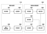
撮影装置110および画像処理装置109のそれぞれの機能構成例を図3のブロック図に示す。図3に示した機能構成例を有する撮影装置110および画像処理装置109によって行われる処理について、図4のフローチャートに従って説明する。なお、以下では図3に示した機能部を処理の主体として説明する。しかし、実際には、撮影装置110の機能部の機能をCPU201に実現させるためのコンピュータプログラムをCPU201が実行することで、撮影装置110の機能部の機能を実現させる。また、画像処理装置109の機能部の機能をCPU209に実現させるためのコンピュータプログラムをCPU209が実行することで、画像処理装置109の機能部の機能を実現させる。なお、図3に示した機能部はハードウェアで実装しても構わない。
The block diagram of FIG. 3 shows an example of the functional configuration of each of the
ステップS401では、撮影装置110の取得部301は、撮影部206によって撮影された撮影画像を取得する。該撮影画像は静止画像であってもよいし、動画像における各フレームの画像であってもよい。
In step S401, the
ステップS402では、撮影装置110の送信部302は、ステップS401で取得部301が取得した撮影画像を画像処理装置109に対して送信する。ステップS403では、画像処理装置109の受信部303は、ステップS402で撮影装置110の送信部302が送信した撮影画像を受信する。
In step S402, the
ステップS404では、画像処理装置109の推定部304は、ステップS403で画像処理装置109の受信部303が受信した撮影画像に基づいて、世界座標系における撮影装置110の位置姿勢(三次元位置および三次元姿勢)を推定する。世界座標系は、実空間における1点を原点とし、該原点で互いに直交する3軸をそれぞれx軸、y軸、z軸とする直交座標系である。本実施形態では一例として、世界座標系は、図1に示したサッカーコートのセンターサークルの中心位置を原点とし、該サッカーコートの長手の辺に沿う軸をy軸、該サッカーコートの短手の辺に沿う軸をx軸、該サッカーコートの面に垂直な方向に沿う軸をz軸、とする直交座標系であるものとする。また以下では、撮影装置110の三次元位置を原点とし、該撮影装置110の三次元姿勢における三成分に対応する軸をそれぞれx軸、y軸、z軸とする直交座標系(撮影装置110の位置姿勢を基準とする直交座標系)をカメラ座標系と称する。また、撮影装置110による撮影画像の中心位置を原点とし、該撮影画像の水平方向をx軸、該撮影画像の垂直方向をy軸、とする直交座標系を画像座標系と称する。
In step S404, the
世界座標系とカメラ座標系と画像座標系との関係を図5に示す。Owは世界座標系の原点、Xw,Yw,Zwはそれぞれ世界座標系におけるx軸、y軸、z軸を示す。Ocはカメラ座標系の原点、Xc,Yc,Zcはそれぞれカメラ座標系におけるx軸、y軸、z軸を示す。Oiは画像座標系の原点、Xi,Yiはそれぞれ画像座標系におけるx軸、y軸を示す。ここで、世界座標系における三次元位置Pw=(Xw,Yw,Zw)をカメラ座標系における三次元位置Pc=(Xc,Yc,Zc)に変換する式は以下のように表される。 The relationship between the world coordinate system, camera coordinate system, and image coordinate system is shown in Figure 5. Ow is the origin of the world coordinate system, and Xw, Yw, and Zw respectively indicate the x-axis, y-axis, and z-axis in the world coordinate system. Oc is the origin of the camera coordinate system, and Xc, Yc, and Zc respectively indicate the x-axis, y-axis, and z-axis in the camera coordinate system. Oi is the origin of the image coordinate system, and Xi and Yi respectively indicate the x-axis and y-axis in the image coordinate system. Here, the equation for converting a three-dimensional position Pw = (Xw, Yw, Zw) in the world coordinate system to a three-dimensional position Pc = (Xc, Yc, Zc) in the camera coordinate system is expressed as follows.

Rは各軸周りの回転行列の合成であり、Tは並進行列である。また、カメラ座標系における三次元位置Pcを、ピンホールカメラモデルに従い、画像座標系における二次元位置Pi=(Xi,Yi)に変換する式は以下のように表される。 R is the composition of the rotation matrices around each axis, and T is the translation matrix. In addition, the equation for converting a three-dimensional position Pc in the camera coordinate system to a two-dimensional position Pi = (Xi, Yi) in the image coordinate system according to the pinhole camera model is expressed as follows.

ここで、λは画像のスケール係数、fは焦点距離、(sx,sy)はそれぞれ、x軸方向の画素の大きさ、y軸方向の画素の大きさ、を示す。また、(xco,yco)は画像主点位置、ksは画像平面におけるx軸に対するyの傾きを表すせん断係数である。 Here, λ is the scale factor of the image, f is the focal length, (s x , s y ) are the pixel size in the x-axis direction and the pixel size in the y-axis direction, respectively, (x co , y co ) is the image principal point position, and ks is the shear coefficient that represents the inclination of y with respect to the x-axis in the image plane.
行列[R T]は、撮影装置110の世界座標系における三次元位置および三次元姿勢を表す外部パラメータ、行列Aは撮影装置110の射影特性を表す内部パラメータと呼ばれ、撮影装置110の位置姿勢の推定は、行列[R T]を推定することである。
The matrix [R T] is called an external parameter that represents the three-dimensional position and three-dimensional orientation of the
撮影装置110の世界座標系における位置姿勢の推定は、いわゆるPnP(Perspective n-Point)問題を解くことにより求めることができる。PnP問題は、複数の三次元点と二次元点の対応および撮影装置110の内部パラメータを既知として、撮影装置110の外部パラメータを推定する問題である。数学的には、既知の対応点が6組以上あれば、外部パラメータを求めることができる。位置姿勢推定手法としてRANSAC(RANdom SAmple Consensus)等が知られている。
The position and orientation of the
このように、本実施形態では、撮影画像中の特徴点の二次元位置と、該特徴点の既知の三次元位置と、上記の内部パラメータと、に基づいて撮影装置110の世界座標系における位置姿勢を推定する。このような、撮影装置110による撮影画像から該撮影装置110の位置姿勢を推定するための技術は周知の技術であるため、これに係る詳細な説明は省略する。なお、撮影装置110の位置姿勢を取得するための方法は特定の方法に限らない。例えば、撮影装置110の位置姿勢をジャイロセンサやGPSセンサ、光学式センサや超音波式センサなどのセンサを用いて取得するようにしてもよいし、センサと撮影画像とを併用して撮影装置110の位置姿勢を取得してもよい。
In this manner, in this embodiment, the position and orientation of the
ステップS405では、画像処理装置109の取得部305は、被写体111の世界座標系における三次元位置を取得する。例えば、撮影装置110は自身が撮影した撮影画像を表示部205に表示して、該撮影画像中の被写体のうち以降の処理の対象となる対象被写体を選択させる。ユーザは表示部205の画面上で対象被写体をタッチしたり操作部204を操作して対象被写体を選択するなどして、対象被写体の選択操作を行う。そして撮影装置110は、この選択された対象被写体を特定するための情報を画像処理装置109に送信する。また例えば、多視点撮影システムにユーザの情報を登録しておき、撮影装置110と対象被写体(選手)を管理できるようにしてもよい。ユーザは携帯端末等から多視点撮影システムにログインし、対象被写体を随時指示できるようにしてもよい。また、対象被写体は複数であってもよい。以下では、対象被写体として被写体111が指定されているケースについて説明する。
In step S405, the
上記の如く画像処理装置109は、仮想視点映像を生成するためのコンピュータプログラムを実行しており、これにより、カメラ101~108が同時刻に撮影した撮影画像から、世界座標系における被写体111の三次元位置および三次元姿勢を推定している。よって、ステップS405では、取得部305は、この推定された被写体111の世界座標系における三次元位置を取得する。
As described above, the
ステップS406では、画像処理装置109の算出部306は上記の式(1)および式(2)を用いて、ステップS405で取得した被写体111の世界座標系における三次元位置から、画像座標系における被写体111の二次元位置を求める。そして算出部306は、画像座標系における被写体111の二次元位置が撮影装置110の画角の範囲外であれば、該二次元位置を該撮影装置110の画角の範囲内に収めるための操作に必要な情報を生成する。
In step S406, the
画像座標系における被写体111の二次元位置の一例を図6に示す。参照番号601は、ステップS406で求めた被写体111の二次元位置、参照番号602は撮影装置110の画角の範囲を示している。撮影装置110の画角の範囲は、上記の内部パラメータから算出可能である。
An example of the two-dimensional position of the subject 111 in the image coordinate system is shown in FIG. 6.
図6に示す如く、取得した二次元位置601は、撮影装置110の画角の範囲602に収まっておらず、よってこのような範囲602の画角で撮影した撮影画像には被写体111は含まれていないことになる。本実施形態では、このようなケースの場合、撮影装置110をどの方向にどの程度向ければ画角の範囲内に被写体111が含まれるのかをユーザに通知する。そのために、算出部306は、画像座標系の原点から二次元位置601に向かう直線と、画角の範囲602の端部と、の交点Epを求め、該交点Epから二次元位置601に向かうベクトル603を求める。このベクトル603の方向が、二次元位置601を撮影装置110の画角の範囲602内に収めるために必要な撮影装置110の移動方向となる。また、このベクトル603の長さが、二次元位置601を撮影装置110の画角の範囲602内に収めるために必要な撮影装置110の移動量となる。
As shown in FIG. 6, the acquired two-
ステップS407では、画像処理装置109の送信部307は、ステップS406で画像処理装置109の算出部306が求めたベクトルの情報(ベクトル情報)を、撮影装置110に対して送信する。ステップS408では、撮影装置110の受信部308は、ステップS407で画像処理装置109の送信部307が送信したベクトル情報を受信する。
In step S407, the
ステップS409では、撮影装置110の表示制御部309は、ステップS408で撮影装置110の受信部308が受信したベクトル情報に基づいて、ステップS406で求めた被写体111の二次元位置を撮影装置110の画角の範囲内に収めるために必要な該撮影装置110の移動量および移動方向をユーザに通知するための通知情報を表示部205に表示させる。
In step S409, the
表示部205における通知情報の表示例を図7(a)に示す。表示部205の表示画面701には撮影画像700が表示されており、該撮影画像701の表示領域を囲む周囲の領域702は、撮影画像700外(つまり撮影装置110の画角の範囲外)に被写体111の二次元位置が存在する場合に、被写体111の二次元位置を撮影装置110の画角の範囲内に収めるために必要な該撮影装置110の移動量および移動方向をユーザに通知するためのアイコン703を表示するための領域である。アイコン703は、撮影画像700の中心位置から上記のベクトルの方向に延長した直線上の位置であって領域702内の位置に配置される。図7(a)では、撮影画像700の中心位置からアイコン703の位置に向かう直線の延長上に、被写体111の二次元位置が存在することを、該アイコン703によってユーザに通知している。つまり、このアイコン703を見たユーザは、撮影画像700の中心位置からアイコン703の位置に向かう方向が「被写体111の二次元位置を撮影装置110の画角の範囲内に収めるために必要な該撮影装置110の移動方向」であると理解することができる。
7A shows an example of the display of notification information on the
また、アイコン703の表示形態によって、「被写体111の二次元位置を撮影装置110の画角の範囲内に収めるために必要な該撮影装置110の移動量」をユーザに通知する。例えば、上記のベクトルの長さが小さい(移動量が小さい)ほどアイコン703のサイズを大きくし、上記のベクトルの長さが大きい(移動量が大きい)ほどアイコン703のサイズを小さくしてもよい。また、上記のベクトルの長さが小さい(移動量が小さい)ほどアイコン703の明度または彩度を上げ、上記のベクトルの長さが大きい(移動量が大きい)ほどアイコン703の明度または彩度を下げるようにしても良い。また、アイコン703のサイズ、明度、彩度のうち2つ以上を上記のベクトルの長さ(移動量)に応じて変えてもよい。上記のベクトルの長さ(移動量)に応じたアイコン703のサイズや色の組合せの一例を図7(b)に示す。
In addition, the display form of the
また、アイコンはユーザが被写体ごとに変えてもよい。例えば、ユーザが対象被写体を選択する際に、対応するアイコンを選択するようにしてもよい。これにより、ユーザは、撮影装置110の画角の範囲外に複数の被写体の二次元位置が存在する場合であっても、被写体ごとに、撮影装置110の移動方向および移動量を把握することができる。
The user may also change the icon for each subject. For example, when the user selects a target subject, the user may select a corresponding icon. This allows the user to grasp the direction and amount of movement of the
なお、通知情報は、上記のようなアイコンに限らない。例えば、図7(a)のアイコン703を、移動方向に向くように傾けてもよい。また、アイコンの形状も図7(a)に示したアイコン703の形状に限らない。また、撮影装置110の移動方向や移動量、被写体の識別情報などを文字情報として表示部205に表示してもよい。
The notification information is not limited to the icon as described above. For example, the
このように本実施形態によれば、撮影装置110の画角の範囲外に位置する被写体の高精度な二次元位置を取得し、該二次元位置を撮影装置110の画角の範囲内に収めるために必要な該撮影装置110の移動量および移動方向をユーザに通知することができる。これにより、撮影装置110の画角の範囲外で被写体が移動した場合であっても、被写体を高精度に追従でき、被写体を見失うことなく画角内に捉えることができる。
As described above, according to this embodiment, it is possible to obtain the highly accurate two-dimensional position of a subject located outside the range of the angle of view of the
[第2の実施形態]
本実施形態を含む以下の各実施形態では、第1の実施形態との差分について説明し、以下で特に触れない限りは第1の実施形態と同様であるものとする。第1の実施形態では、画像処理装置109が撮影装置110の移動方向および移動量を求めて撮影装置110に通知する構成とした。これによれば、撮影装置110の計算性能が低い場合でも、上記の処理を実施できる。しかしながら、画像処理装置109に撮影装置110が複数接続されている場合は、画像処理装置109の計算負荷が高くなってしまう。そこで、本実施形態では、撮影装置110が自身の移動方向および移動量を求めるための構成について説明する。
Second Embodiment
In the following embodiments including this embodiment, the difference from the first embodiment will be described, and it will be assumed that the embodiments are the same as the first embodiment unless otherwise specified below. In the first embodiment, the
撮影装置110および画像処理装置109のそれぞれの機能構成例を図8のブロック図に示す。図8に示した機能構成例を有する撮影装置110および画像処理装置109によって行われる処理について、図9のフローチャートに従って説明する。なお、以下では図8に示した機能部を処理の主体として説明する。しかし、実際には、撮影装置110の機能部の機能をCPU201に実現させるためのコンピュータプログラムをCPU201が実行することで、撮影装置110の機能部の機能を実現させる。また、画像処理装置109の機能部の機能をCPU209に実現させるためのコンピュータプログラムをCPU209が実行することで、画像処理装置109の機能部の機能を実現させる。なお、図8に示した機能部はハードウェアで実装しても構わない。
The block diagram of FIG. 8 shows an example of the functional configuration of each of the
ステップS401では、撮影装置110の取得部301は、撮影部206によって撮影された撮影画像を取得する。ステップS901では、画像処理装置109の送信部801は、撮影装置110による撮影画像から該撮影装置110の位置姿勢を推定する際に基準とする実空間中のオブジェクトの情報を基準点情報として、撮影装置110に対して送信する。「撮影装置110の位置姿勢を推定する際に基準とする実空間中のオブジェクト」は、実空間において位置が変化しないオブジェクト(例えば、ゴールやフラッグなどの構造物やフィールド上のラインなど)である。基準点情報は、このようなオブジェクトの色や三次元位置等を含む。
In step S401, the
ステップS902では、撮影装置110の受信部802は、ステップS901において画像処理装置109の送信部801により送信された基準点情報を受信する。ステップS903では、撮影装置110の推定部803は、ステップS401で取得した撮影画像と、ステップS902で受信した基準点情報と、に基づいて、世界座標系における撮影装置110の位置姿勢(三次元位置および三次元姿勢)を推定する。本ステップにおける位置姿勢の推定方法は、上記のステップS404における推定方法と同様である。
In step S902, the receiving
ステップS405では、画像処理装置109の取得部305は、被写体111の世界座標系における三次元位置を取得する。ステップS904では、画像処理装置109の送信部804は、ステップS405で取得した被写体111の世界座標系における三次元位置を撮影装置110に対して送信する。
In step S405, the
ステップS905では、撮影装置110の受信部805は、ステップS904において画像処理装置109の送信部804が送信した、被写体111の世界座標系における三次元位置を受信する。
In step S905, the receiving
ステップS906では、算出部806は、上記のステップS406と同様にして、画像座標系における被写体111の二次元位置を求める。そして算出部806は、画像座標系における被写体111の二次元位置が撮影装置110の画角の範囲外であれば、該二次元位置を該撮影装置110の画角の範囲内に収めるための操作に必要な情報を生成する。
In step S906, the
ステップS409では表示制御部309は、第1の実施形態と同様に、被写体111の二次元位置を撮影装置110の画角の範囲内に収めるために必要な該撮影装置110の移動量および移動方向をユーザに通知するための通知情報を表示部205に表示させる。
In step S409, the
このように、本実施形態によれば、画像処理装置109に撮影装置110が複数接続されている場合であっても、画像処理装置109の負荷を抑えることができ、多くの撮影装置110で処理を実施できる。
In this way, according to this embodiment, even if multiple
[第3の実施形態]
第1,2の実施形態では、被写体111の二次元位置を撮影装置110の画角の範囲内に収めるために必要な該撮影装置110の移動量および移動方向をユーザに通知している。これによれば、ユーザは被写体111が画角外のどこに位置しているのか把握することができる。しかしながら、被写体111の移動速度が速い場合、被写体111を画角内に収めるべく撮影装置110の位置や姿勢を変更しても、その間に被写体111は移動しているため、該被写体111を画角内に捉えることが難しい。
[Third embodiment]
In the first and second embodiments, the user is notified of the amount and direction of movement of the
そこで、本実施形態では、被写体111の二次元位置を撮影装置110の画角の範囲内に収めるために必要な該撮影装置110の移動量および移動方向に加え、被写体111の移動速度および移動方向をユーザに通知する。撮影装置110および画像処理装置109によって行われる処理について、図10のフローチャートに従って説明する。
Therefore, in this embodiment, in addition to the amount and direction of movement of the
ステップS1001では、取得部305は、現在よりも所定時間前の被写体111の世界座標系における三次元位置を取得する。ステップS1001で取得する三次元位置は、仮想視点映像を生成するためのコンピュータプログラムの実行により所定時間前に推定した世界座標系における被写体111の三次元位置である。なお、この「所定時間」は、被写体111の移動速度を算出するにあたり必要な時間を設定すればよい。例えば、被写体111が人物である場合は、2~5秒程度の期間を設定すればよい。また、所定時間をより短く設定し、算出した移動速度を過去の結果と合成して移動速度を算出してもよい。
In step S1001, the
ステップS1002では、算出部306は、上記の式(1)および式(2)を用いて上記のステップS406と同様の処理を行うことで、ステップS1001で取得した被写体111の世界座標系における三次元位置から、画像座標系における被写体111の二次元位置を求める。そして算出部306はステップS1002で求めた被写体111の所定時間前の二次元位置を始点とし、ステップS406で求めた被写体111の最新の二次元位置を終点とするベクトルを「被写体111の移動ベクトル(二次元の移動ベクトル)」として求める。移動ベクトルの方向が被写体111の移動方向、移動ベクトルの長さが被写体111の移動速度、を表している。
In step S1002, the
図11に被写体111の移動ベクトルの一例を示す。図11では、ステップS1002で求めた被写体111の所定時間前の二次元位置1101を始点とし、ステップS406で求めた被写体111の最新の二次元位置601を終点とするベクトル1102を「被写体111の移動ベクトル」としている。
Figure 11 shows an example of the movement vector of
ステップS1003では、送信部307は、ステップS406で求めたベクトルの情報(ベクトル情報)に加え、ステップS1002で求めた被写体111の移動ベクトルの情報(移動ベクトル情報)を撮影装置110に対して送信する。ステップS1004では、受信部308は、ステップS1003で送信部307が送信したベクトル情報および移動ベクトル情報を受信する。
In step S1003, the
ステップS1005では、表示制御部309は、ステップS1004で受信したベクトル情報に基づいて、ステップS406で求めた被写体111の二次元位置を撮影装置110の画角の範囲内に収めるために必要な該撮影装置110の移動量および移動方向をユーザに通知するための通知情報を表示部205に表示させる。さらに表示制御部309は、ステップS1004で受信した移動ベクトル情報に基づいて、被写体111の移動に関する情報をユーザに通知するための通知情報を表示部205に表示させる。
In step S1005, the
表示部205における通知情報の表示例を図12(a)に示す。本実施形態では、領域702には、撮影画像700外(撮影装置110の画角の範囲外)に被写体111の二次元位置が存在する場合に、上記のアイコン703に加え、上記の移動ベクトルの方向および長さに応じた移動情報アイコン1201を通知情報として表示する。
An example of the display of notification information on the
本実施形態では、表示制御部309は、図12(b)に示すテーブルを参照し、移動ベクトルの方向および長さに対応する移動情報アイコンを選択して表示する。より詳しくは、表示制御部309は、8方向(上、右上、右、右下、下、左下、左、左上)のうち移動ベクトルの方向に最も近い移動方向と、3種類の移動速度(歩行、走行、全速力)のうち移動ベクトルの長さに対応する移動速度に最も近い移動速度と、の組合せに対応する移動情報アイコンを選択して表示する。
In this embodiment, the
図12(b)の例では、例えば、移動ベクトルの長さが第1の値未満、つまり該被写体が停止している場合は矢印は表示しない。移動ベクトルの長さが第1の値以上かつ第2の値未満、つまり歩行速度の場合は矢先の数が一つの移動情報アイコンを表示する。移動ベクトルの長さが第2の値以上かつ第3の値未満、つまり走行速度の場合は矢先の数が二つの移動情報アイコンを表示する。移動ベクトルの長さが第3の値以上、つまり全速力速度の場合は矢先の数が三つの移動情報アイコンを表示する。 In the example of FIG. 12(b), for example, if the length of the movement vector is less than the first value, i.e., the subject is stationary, no arrow is displayed. If the length of the movement vector is equal to or greater than the first value and less than the second value, i.e., walking speed, a movement information icon with one arrow tip is displayed. If the length of the movement vector is equal to or greater than the second value and less than the third value, i.e., running speed, a movement information icon with two arrow tips is displayed. If the length of the movement vector is equal to or greater than the third value, i.e., full sprinting speed, a movement information icon with three arrow tips is displayed.
なお、移動ベクトルに関する情報を表示するのであれば、移動情報アイコンに加えて若しくは代えて、他の情報を表示するようにしてもよい。例えば移動情報アイコンに加えて若しくは代えて、移動ベクトルの方向および長さを文字情報として表示してもよい。 When displaying information about a movement vector, other information may be displayed in addition to or instead of the movement information icon. For example, the direction and length of the movement vector may be displayed as text information in addition to or instead of the movement information icon.
このように、本実施形態によれば、ユーザは、被写体の移動先を予測して撮影装置110の位置や向きを変更することができるため、被写体を追従して撮影することができる。
In this way, according to this embodiment, the user can predict the destination of the subject and change the position and orientation of the
上記の説明において使用した数値、処理タイミング、処理順、表示画面の構成、表示する情報、表示形態、処理の主体などは、具体的な説明を行うために一例として挙げたものであり、これらの一例に限定することを意図したものではない。 The numerical values, processing timing, processing order, display screen configuration, information to be displayed, display format, processing subject, etc. used in the above explanation are given as examples to provide a concrete explanation, and are not intended to be limiting.
また、以上説明した各実施形態の一部若しくは全部を適宜組み合わせて使用しても構わない。また、以上説明した各実施形態の一部若しくは全部を選択的に使用しても構わない。 Furthermore, any or all of the embodiments described above may be used in appropriate combination.Furthermore, any or all of the embodiments described above may be used selectively.
(その他の実施形態)
本発明は、上述の実施形態の1以上の機能を実現するプログラムを、ネットワーク又は記憶媒体を介してシステム又は装置に供給し、そのシステム又は装置のコンピュータにおける1つ以上のプロセッサがプログラムを読出し実行する処理でも実現可能である。また、1以上の機能を実現する回路(例えば、ASIC)によっても実現可能である。
Other Embodiments
The present invention can also be realized by a process in which a program for implementing one or more of the functions of the above-described embodiments is supplied to a system or device via a network or a storage medium, and one or more processors in a computer of the system or device read and execute the program. The present invention can also be realized by a circuit (e.g., ASIC) that implements one or more of the functions.
発明は上記実施形態に制限されるものではなく、発明の精神及び範囲から離脱することなく、様々な変更及び変形が可能である。従って、発明の範囲を公にするために請求項を添付する。 The invention is not limited to the above-described embodiment, and various modifications and variations are possible without departing from the spirit and scope of the invention. Therefore, the following claims are appended to disclose the scope of the invention.
109:画像処理装置 110:撮影装置 301:取得部 302:送信部 303:受信部 304:推定部 305:取得部 306:算出部 307:送信部 308:受信部 309:表示制御部 109: Image processing device 110: Image capture device 301: Acquisition unit 302: Transmission unit 303: Reception unit 304: Estimation unit 305: Acquisition unit 306: Calculation unit 307: Transmission unit 308: Reception unit 309: Display control unit
Claims (14)
前記撮影装置の三次元位置および三次元姿勢と、被写体を取り囲むように配置された複数のカメラが撮影した撮影画像から推定される被写体の三次元位置とに基づいて、前記撮影装置による撮影画像を基準とする座標系における該被写体の二次元位置を求める取得手段と、
前記二次元位置が前記撮影装置の画角の範囲外であれば、該二次元位置を該撮影装置の画角の範囲内に収めるための操作に必要な情報を求め、該求めた情報に基づく表示を行う表示制御手段と
を備えることを特徴とする撮影装置。 An imaging device,
an acquisition means for determining a two-dimensional position of the subject in a coordinate system based on the images captured by the photographing device, based on the three-dimensional position and three-dimensional orientation of the photographing device and the three-dimensional position of the subject estimated from the images captured by a plurality of cameras arranged to surround the subject;
and if the two-dimensional position is outside the range of the angle of view of the imaging device, obtaining information necessary for an operation to bring the two-dimensional position within the range of the angle of view of the imaging device, and performing a display based on the obtained information.
前記二次元位置が前記撮影装置の画角の範囲外であれば、該二次元位置を該撮影装置の画角の範囲内に収めるための操作に必要な情報を求め、該求めた情報を前記撮影装置に対して送信する送信手段と
を備えることを特徴とする画像処理装置。 an acquisition means for determining a two-dimensional position of the subject in a coordinate system based on the images captured by the imaging device, based on the three-dimensional position and three-dimensional orientation of the imaging device and the three-dimensional position of the subject estimated from images captured by a plurality of cameras arranged to surround the subject;
and a transmission means for, if the two-dimensional position is outside the range of the angle of view of the image capturing device, obtaining information necessary for an operation to bring the two-dimensional position within the range of the angle of view of the image capturing device, and transmitting the obtained information to the image capturing device.
前記取得手段が求めた前記被写体の二次元位置に基づいて、該被写体の二次元の移動ベクトルを求める手段を備え、
前記送信手段は、前記情報に加え、前記移動ベクトルの情報を前記撮影装置に対して送信することを特徴とする請求項6または7に記載の画像処理装置。 Furthermore,
a means for calculating a two-dimensional movement vector of the object based on the two-dimensional position of the object calculated by the calculation means,
8. The image processing apparatus according to claim 6, wherein said transmission means transmits information on said motion vector to said image capturing apparatus in addition to said information.
前記撮影装置の取得手段が、前記撮影装置の三次元位置および三次元姿勢と、被写体を取り囲むように配置された複数のカメラが撮影した撮影画像から推定される被写体の三次元位置とに基づいて、前記撮影装置による撮影画像を基準とする座標系における該被写体の二次元位置を求める取得工程と、
前記撮影装置の表示制御手段が、前記二次元位置が前記撮影装置の画角の範囲外であれば、該二次元位置を該撮影装置の画角の範囲内に収めるための操作に必要な情報を求め、該求めた情報に基づく表示を行う表示制御工程と
を備えることを特徴とする撮影装置の制御方法。 A method for controlling an imaging device, comprising:
an acquisition step in which an acquisition means of the image capturing device acquires a two-dimensional position of the subject in a coordinate system based on the images captured by the image capturing device, based on the three-dimensional position and three-dimensional attitude of the image capturing device and the three-dimensional position of the subject estimated from the images captured by a plurality of cameras arranged to surround the subject;
and a display control step in which, if the two-dimensional position is outside the range of the angle of view of the photographing device, a display control means of the photographing device obtains information necessary for an operation to bring the two-dimensional position within the range of the angle of view of the photographing device, and performs a display based on the obtained information.
前記画像処理装置の取得手段が、撮影装置の三次元位置および三次元姿勢と、被写体を取り囲むように配置された複数のカメラが撮影した撮影画像から推定される被写体の三次元位置とに基づいて、該撮影装置による撮影画像を基準とする座標系における該被写体の二次元位置を求める取得工程と、
前記画像処理装置の送信手段が、前記二次元位置が前記撮影装置の画角の範囲外であれば、該二次元位置を該撮影装置の画角の範囲内に収めるための操作に必要な情報を求め、該求めた情報を前記撮影装置に対して送信する送信工程と
を備えることを特徴とする画像処理装置の制御方法。 A control method for an image processing device, comprising:
an acquisition step in which an acquisition means of the image processing device determines a two-dimensional position of the subject in a coordinate system based on the images captured by the imaging device, based on the three-dimensional position and three-dimensional attitude of the imaging device and the three-dimensional position of the subject estimated from the images captured by a plurality of cameras arranged to surround the subject;
a transmission step in which, if the two-dimensional position is outside the range of the angle of view of the photographing device, a transmission means of the image processing device obtains information necessary for an operation to bring the two-dimensional position within the range of the angle of view of the photographing device, and transmits the obtained information to the photographing device.
前記画像処理装置は、
前記撮影装置の三次元位置および三次元姿勢と、被写体を取り囲むように配置された複数のカメラが撮影した撮影画像から推定される被写体の三次元位置とに基づいて、該撮影装置による撮影画像を基準とする座標系における該被写体の二次元位置を求める取得手段と、
前記二次元位置が前記撮影装置の画角の範囲外であれば、該二次元位置を該撮影装置の画角の範囲内に収めるための操作に必要な情報を求め、該求めた情報を前記撮影装置に対して送信する送信手段と
を備え、
前記撮影装置は、
前記送信手段が送信した情報を受信する受信手段と、
前記受信手段が受信した情報に基づく表示を行う表示制御手段と
を備えることを特徴とする撮影システム。 A photographing system having a photographing device and an image processing device,
The image processing device includes:
an acquisition means for determining a two-dimensional position of the subject in a coordinate system based on the images captured by the imaging device, based on the three-dimensional position and three-dimensional orientation of the imaging device and the three-dimensional position of the subject estimated from images captured by a plurality of cameras arranged to surround the subject;
a transmitting means for, if the two-dimensional position is outside the range of the angle of view of the image capture device, obtaining information required for an operation to bring the two-dimensional position within the range of the angle of view of the image capture device, and transmitting the obtained information to the image capture device;
The imaging device is
a receiving means for receiving the information transmitted by the transmitting means;
and a display control means for performing a display based on the information received by the receiving means.
前記撮影装置は、
前記撮影装置の三次元位置および三次元姿勢と被写体の三次元位置とに基づいて、前記撮影装置による撮影画像を基準とする座標系における該被写体の二次元位置を求める取得手段と、
前記二次元位置が前記撮影装置の画角の範囲外であれば、該二次元位置を該撮影装置の画角の範囲内に収めるための操作に必要な情報を求め、該求めた情報に基づく表示を行う表示制御手段と
を備え、
前記画像処理装置は、
複数のカメラによる撮影画像に基づいて被写体の三次元位置を推定する推定手段と、
前記推定手段が推定した前記被写体の三次元位置を前記撮影装置に対して送信する手段と
を備えることを特徴とする撮影システム。 A photographing system having a photographing device and an image processing device,
The imaging device is
an acquisition means for acquiring a two-dimensional position of the subject in a coordinate system based on an image captured by the photographing device, based on the three-dimensional position and three-dimensional attitude of the photographing device and the three-dimensional position of the subject;
a display control means for, if the two-dimensional position is outside the range of the angle of view of the image capture device, obtaining information necessary for an operation to bring the two-dimensional position into the range of the angle of view of the image capture device, and performing a display based on the obtained information;
The image processing device includes:
An estimation means for estimating a three-dimensional position of a subject based on images captured by a plurality of cameras;
and a means for transmitting the three-dimensional position of the subject estimated by the estimation means to the imaging device.
Priority Applications (1)
| Application Number | Priority Date | Filing Date | Title |
|---|---|---|---|
| JP2020123913A JP7561533B2 (en) | 2020-07-20 | 2020-07-20 | Photographing device, image processing device, control method for photographing device, control method for image processing device, and photographing system |
Applications Claiming Priority (1)
| Application Number | Priority Date | Filing Date | Title |
|---|---|---|---|
| JP2020123913A JP7561533B2 (en) | 2020-07-20 | 2020-07-20 | Photographing device, image processing device, control method for photographing device, control method for image processing device, and photographing system |
Publications (2)
| Publication Number | Publication Date |
|---|---|
| JP2022020429A JP2022020429A (en) | 2022-02-01 |
| JP7561533B2 true JP7561533B2 (en) | 2024-10-04 |
Family
ID=80216068
Family Applications (1)
| Application Number | Title | Priority Date | Filing Date |
|---|---|---|---|
| JP2020123913A Active JP7561533B2 (en) | 2020-07-20 | 2020-07-20 | Photographing device, image processing device, control method for photographing device, control method for image processing device, and photographing system |
Country Status (1)
| Country | Link |
|---|---|
| JP (1) | JP7561533B2 (en) |
Citations (5)
| Publication number | Priority date | Publication date | Assignee | Title |
|---|---|---|---|---|
| JP2002247441A (en) | 2001-02-22 | 2002-08-30 | Oyo Keisoku Kenkyusho:Kk | Subject recognition method and automatic photographing camera device using the same |
| JP2002314851A (en) | 2001-04-10 | 2002-10-25 | Nikon Corp | Imaging equipment |
| JP2011199750A (en) | 2010-03-23 | 2011-10-06 | Olympus Corp | Image capturing terminal, external terminal, image capturing system, and image capturing method |
| JP2015153035A (en) | 2014-02-12 | 2015-08-24 | 日本電信電話株式会社 | Subject information superimposition apparatus, subject information superimposition method, and program |
| WO2019021375A1 (en) | 2017-07-25 | 2019-01-31 | 富士通株式会社 | Video generation program, video generation method, and video generation device |
-
2020
- 2020-07-20 JP JP2020123913A patent/JP7561533B2/en active Active
Patent Citations (5)
| Publication number | Priority date | Publication date | Assignee | Title |
|---|---|---|---|---|
| JP2002247441A (en) | 2001-02-22 | 2002-08-30 | Oyo Keisoku Kenkyusho:Kk | Subject recognition method and automatic photographing camera device using the same |
| JP2002314851A (en) | 2001-04-10 | 2002-10-25 | Nikon Corp | Imaging equipment |
| JP2011199750A (en) | 2010-03-23 | 2011-10-06 | Olympus Corp | Image capturing terminal, external terminal, image capturing system, and image capturing method |
| JP2015153035A (en) | 2014-02-12 | 2015-08-24 | 日本電信電話株式会社 | Subject information superimposition apparatus, subject information superimposition method, and program |
| WO2019021375A1 (en) | 2017-07-25 | 2019-01-31 | 富士通株式会社 | Video generation program, video generation method, and video generation device |
Also Published As
| Publication number | Publication date |
|---|---|
| JP2022020429A (en) | 2022-02-01 |
Similar Documents
| Publication | Publication Date | Title |
|---|---|---|
| CN110460835B (en) | Image processing apparatus, control method thereof, and computer-readable storage medium | |
| JP7051457B2 (en) | Image processing equipment, image processing methods, and programs | |
| JP7349793B2 (en) | Image processing device, image processing method, and program | |
| KR102316061B1 (en) | Image processing apparatus, method, and computer program | |
| JP5430565B2 (en) | Electronic mirror device | |
| CN116309854B (en) | Method, device, equipment, system and storage medium for calibrating augmented reality equipment | |
| US20140118557A1 (en) | Method and apparatus for providing camera calibration | |
| CN110873717B (en) | Image acquisition device and working method of image acquisition device | |
| JP2018106496A (en) | Image processing apparatus, image processing method, and program | |
| JP6723720B2 (en) | Display system, information processing method and program | |
| JP7027049B2 (en) | Image processing equipment, image processing methods and programs | |
| JP2004235934A (en) | Calibration processing device, calibration processing method, and computer program | |
| JP2025172128A (en) | Photographing instruction method and photographing instruction device | |
| JP2010283529A (en) | Display control device, display device control method, program, and storage medium | |
| US11468258B2 (en) | Information processing apparatus, information processing method, and storage medium | |
| WO2023199583A1 (en) | Viewer control method and information processing device | |
| JP2019144958A (en) | Image processing device, image processing method, and program | |
| US20240346745A1 (en) | Image processing apparatus, method for controlling the same, and non-transitory computer-readable storage medium | |
| CN112073632A (en) | Image processing method, apparatus and storage medium | |
| TWI694719B (en) | Image processing method, electronic device, and non-transitory computer readable storage medium | |
| JP2006017632A (en) | Three-dimensional image processing apparatus, optical axis adjustment method, and optical axis adjustment support method | |
| JP7561533B2 (en) | Photographing device, image processing device, control method for photographing device, control method for image processing device, and photographing system | |
| JP2014123208A (en) | Three-dimensional restoration device | |
| JP7710185B2 (en) | Photographing device, photographing operation support method, and photographing operation support program | |
| JP2012199759A (en) | Information processing device, program therefor, and information processing method |
Legal Events
| Date | Code | Title | Description |
|---|---|---|---|
| RD01 | Notification of change of attorney |
Free format text: JAPANESE INTERMEDIATE CODE: A7421 Effective date: 20210103 |
|
| A521 | Request for written amendment filed |
Free format text: JAPANESE INTERMEDIATE CODE: A523 Effective date: 20210113 |
|
| A621 | Written request for application examination |
Free format text: JAPANESE INTERMEDIATE CODE: A621 Effective date: 20230719 |
|
| A977 | Report on retrieval |
Free format text: JAPANESE INTERMEDIATE CODE: A971007 Effective date: 20240524 |
|
| A131 | Notification of reasons for refusal |
Free format text: JAPANESE INTERMEDIATE CODE: A131 Effective date: 20240603 |
|
| A521 | Request for written amendment filed |
Free format text: JAPANESE INTERMEDIATE CODE: A523 Effective date: 20240716 |
|
| TRDD | Decision of grant or rejection written | ||
| A01 | Written decision to grant a patent or to grant a registration (utility model) |
Free format text: JAPANESE INTERMEDIATE CODE: A01 Effective date: 20240826 |
|
| A61 | First payment of annual fees (during grant procedure) |
Free format text: JAPANESE INTERMEDIATE CODE: A61 Effective date: 20240924 |
|
| R150 | Certificate of patent or registration of utility model |
Ref document number: 7561533 Country of ref document: JP Free format text: JAPANESE INTERMEDIATE CODE: R150 |