JP7561530B2 - Film forming method and film forming apparatus - Google Patents
Film forming method and film forming apparatus Download PDFInfo
- Publication number
- JP7561530B2 JP7561530B2 JP2020109733A JP2020109733A JP7561530B2 JP 7561530 B2 JP7561530 B2 JP 7561530B2 JP 2020109733 A JP2020109733 A JP 2020109733A JP 2020109733 A JP2020109733 A JP 2020109733A JP 7561530 B2 JP7561530 B2 JP 7561530B2
- Authority
- JP
- Japan
- Prior art keywords
- gas
- aromatic hydrocarbon
- film
- hydrocarbon gas
- substrate
- Prior art date
- Legal status (The legal status is an assumption and is not a legal conclusion. Google has not performed a legal analysis and makes no representation as to the accuracy of the status listed.)
- Active
Links
Images


Classifications
-
- C—CHEMISTRY; METALLURGY
- C01—INORGANIC CHEMISTRY
- C01B—NON-METALLIC ELEMENTS; COMPOUNDS THEREOF; METALLOIDS OR COMPOUNDS THEREOF NOT COVERED BY SUBCLASS C01C
- C01B32/00—Carbon; Compounds thereof
- C01B32/15—Nano-sized carbon materials
- C01B32/182—Graphene
- C01B32/184—Preparation
- C01B32/186—Preparation by chemical vapour deposition [CVD]
-
- C—CHEMISTRY; METALLURGY
- C23—COATING METALLIC MATERIAL; COATING MATERIAL WITH METALLIC MATERIAL; CHEMICAL SURFACE TREATMENT; DIFFUSION TREATMENT OF METALLIC MATERIAL; COATING BY VACUUM EVAPORATION, BY SPUTTERING, BY ION IMPLANTATION OR BY CHEMICAL VAPOUR DEPOSITION, IN GENERAL; INHIBITING CORROSION OF METALLIC MATERIAL OR INCRUSTATION IN GENERAL
- C23C—COATING METALLIC MATERIAL; COATING MATERIAL WITH METALLIC MATERIAL; SURFACE TREATMENT OF METALLIC MATERIAL BY DIFFUSION INTO THE SURFACE, BY CHEMICAL CONVERSION OR SUBSTITUTION; COATING BY VACUUM EVAPORATION, BY SPUTTERING, BY ION IMPLANTATION OR BY CHEMICAL VAPOUR DEPOSITION, IN GENERAL
- C23C16/00—Chemical coating by decomposition of gaseous compounds, without leaving reaction products of surface material in the coating, i.e. chemical vapour deposition [CVD] processes
- C23C16/02—Pretreatment of the material to be coated
- C23C16/0272—Deposition of sub-layers, e.g. to promote the adhesion of the main coating
-
- C—CHEMISTRY; METALLURGY
- C23—COATING METALLIC MATERIAL; COATING MATERIAL WITH METALLIC MATERIAL; CHEMICAL SURFACE TREATMENT; DIFFUSION TREATMENT OF METALLIC MATERIAL; COATING BY VACUUM EVAPORATION, BY SPUTTERING, BY ION IMPLANTATION OR BY CHEMICAL VAPOUR DEPOSITION, IN GENERAL; INHIBITING CORROSION OF METALLIC MATERIAL OR INCRUSTATION IN GENERAL
- C23C—COATING METALLIC MATERIAL; COATING MATERIAL WITH METALLIC MATERIAL; SURFACE TREATMENT OF METALLIC MATERIAL BY DIFFUSION INTO THE SURFACE, BY CHEMICAL CONVERSION OR SUBSTITUTION; COATING BY VACUUM EVAPORATION, BY SPUTTERING, BY ION IMPLANTATION OR BY CHEMICAL VAPOUR DEPOSITION, IN GENERAL
- C23C16/00—Chemical coating by decomposition of gaseous compounds, without leaving reaction products of surface material in the coating, i.e. chemical vapour deposition [CVD] processes
- C23C16/22—Chemical coating by decomposition of gaseous compounds, without leaving reaction products of surface material in the coating, i.e. chemical vapour deposition [CVD] processes characterised by the deposition of inorganic material, other than metallic material
- C23C16/26—Deposition of carbon only
-
- C—CHEMISTRY; METALLURGY
- C23—COATING METALLIC MATERIAL; COATING MATERIAL WITH METALLIC MATERIAL; CHEMICAL SURFACE TREATMENT; DIFFUSION TREATMENT OF METALLIC MATERIAL; COATING BY VACUUM EVAPORATION, BY SPUTTERING, BY ION IMPLANTATION OR BY CHEMICAL VAPOUR DEPOSITION, IN GENERAL; INHIBITING CORROSION OF METALLIC MATERIAL OR INCRUSTATION IN GENERAL
- C23C—COATING METALLIC MATERIAL; COATING MATERIAL WITH METALLIC MATERIAL; SURFACE TREATMENT OF METALLIC MATERIAL BY DIFFUSION INTO THE SURFACE, BY CHEMICAL CONVERSION OR SUBSTITUTION; COATING BY VACUUM EVAPORATION, BY SPUTTERING, BY ION IMPLANTATION OR BY CHEMICAL VAPOUR DEPOSITION, IN GENERAL
- C23C16/00—Chemical coating by decomposition of gaseous compounds, without leaving reaction products of surface material in the coating, i.e. chemical vapour deposition [CVD] processes
- C23C16/44—Chemical coating by decomposition of gaseous compounds, without leaving reaction products of surface material in the coating, i.e. chemical vapour deposition [CVD] processes characterised by the method of coating
- C23C16/4401—Means for minimising impurities, e.g. dust, moisture or residual gas, in the reaction chamber
- C23C16/4408—Means for minimising impurities, e.g. dust, moisture or residual gas, in the reaction chamber by purging residual gases from the reaction chamber or gas lines
-
- C—CHEMISTRY; METALLURGY
- C23—COATING METALLIC MATERIAL; COATING MATERIAL WITH METALLIC MATERIAL; CHEMICAL SURFACE TREATMENT; DIFFUSION TREATMENT OF METALLIC MATERIAL; COATING BY VACUUM EVAPORATION, BY SPUTTERING, BY ION IMPLANTATION OR BY CHEMICAL VAPOUR DEPOSITION, IN GENERAL; INHIBITING CORROSION OF METALLIC MATERIAL OR INCRUSTATION IN GENERAL
- C23C—COATING METALLIC MATERIAL; COATING MATERIAL WITH METALLIC MATERIAL; SURFACE TREATMENT OF METALLIC MATERIAL BY DIFFUSION INTO THE SURFACE, BY CHEMICAL CONVERSION OR SUBSTITUTION; COATING BY VACUUM EVAPORATION, BY SPUTTERING, BY ION IMPLANTATION OR BY CHEMICAL VAPOUR DEPOSITION, IN GENERAL
- C23C16/00—Chemical coating by decomposition of gaseous compounds, without leaving reaction products of surface material in the coating, i.e. chemical vapour deposition [CVD] processes
- C23C16/44—Chemical coating by decomposition of gaseous compounds, without leaving reaction products of surface material in the coating, i.e. chemical vapour deposition [CVD] processes characterised by the method of coating
- C23C16/455—Chemical coating by decomposition of gaseous compounds, without leaving reaction products of surface material in the coating, i.e. chemical vapour deposition [CVD] processes characterised by the method of coating characterised by the method used for introducing gases into reaction chamber or for modifying gas flows in reaction chamber
- C23C16/45523—Pulsed gas flow or change of composition over time
- C23C16/45525—Atomic layer deposition [ALD]
- C23C16/45527—Atomic layer deposition [ALD] characterized by the ALD cycle, e.g. different flows or temperatures during half-reactions, unusual pulsing sequence, use of precursor mixtures or auxiliary reactants or activations
- C23C16/45536—Use of plasma, radiation or electromagnetic fields
- C23C16/45542—Plasma being used non-continuously during the ALD reactions
-
- C—CHEMISTRY; METALLURGY
- C23—COATING METALLIC MATERIAL; COATING MATERIAL WITH METALLIC MATERIAL; CHEMICAL SURFACE TREATMENT; DIFFUSION TREATMENT OF METALLIC MATERIAL; COATING BY VACUUM EVAPORATION, BY SPUTTERING, BY ION IMPLANTATION OR BY CHEMICAL VAPOUR DEPOSITION, IN GENERAL; INHIBITING CORROSION OF METALLIC MATERIAL OR INCRUSTATION IN GENERAL
- C23C—COATING METALLIC MATERIAL; COATING MATERIAL WITH METALLIC MATERIAL; SURFACE TREATMENT OF METALLIC MATERIAL BY DIFFUSION INTO THE SURFACE, BY CHEMICAL CONVERSION OR SUBSTITUTION; COATING BY VACUUM EVAPORATION, BY SPUTTERING, BY ION IMPLANTATION OR BY CHEMICAL VAPOUR DEPOSITION, IN GENERAL
- C23C16/00—Chemical coating by decomposition of gaseous compounds, without leaving reaction products of surface material in the coating, i.e. chemical vapour deposition [CVD] processes
- C23C16/44—Chemical coating by decomposition of gaseous compounds, without leaving reaction products of surface material in the coating, i.e. chemical vapour deposition [CVD] processes characterised by the method of coating
- C23C16/50—Chemical coating by decomposition of gaseous compounds, without leaving reaction products of surface material in the coating, i.e. chemical vapour deposition [CVD] processes characterised by the method of coating using electric discharges
- C23C16/511—Chemical coating by decomposition of gaseous compounds, without leaving reaction products of surface material in the coating, i.e. chemical vapour deposition [CVD] processes characterised by the method of coating using electric discharges using microwave discharges
-
- C—CHEMISTRY; METALLURGY
- C23—COATING METALLIC MATERIAL; COATING MATERIAL WITH METALLIC MATERIAL; CHEMICAL SURFACE TREATMENT; DIFFUSION TREATMENT OF METALLIC MATERIAL; COATING BY VACUUM EVAPORATION, BY SPUTTERING, BY ION IMPLANTATION OR BY CHEMICAL VAPOUR DEPOSITION, IN GENERAL; INHIBITING CORROSION OF METALLIC MATERIAL OR INCRUSTATION IN GENERAL
- C23C—COATING METALLIC MATERIAL; COATING MATERIAL WITH METALLIC MATERIAL; SURFACE TREATMENT OF METALLIC MATERIAL BY DIFFUSION INTO THE SURFACE, BY CHEMICAL CONVERSION OR SUBSTITUTION; COATING BY VACUUM EVAPORATION, BY SPUTTERING, BY ION IMPLANTATION OR BY CHEMICAL VAPOUR DEPOSITION, IN GENERAL
- C23C16/00—Chemical coating by decomposition of gaseous compounds, without leaving reaction products of surface material in the coating, i.e. chemical vapour deposition [CVD] processes
- C23C16/44—Chemical coating by decomposition of gaseous compounds, without leaving reaction products of surface material in the coating, i.e. chemical vapour deposition [CVD] processes characterised by the method of coating
- C23C16/52—Controlling or regulating the coating process
-
- H—ELECTRICITY
- H10—SEMICONDUCTOR DEVICES; ELECTRIC SOLID-STATE DEVICES NOT OTHERWISE PROVIDED FOR
- H10P—GENERIC PROCESSES OR APPARATUS FOR THE MANUFACTURE OR TREATMENT OF DEVICES COVERED BY CLASS H10
- H10P14/00—Formation of materials, e.g. in the shape of layers or pillars
- H10P14/60—Formation of materials, e.g. in the shape of layers or pillars of insulating materials
- H10P14/63—Formation of materials, e.g. in the shape of layers or pillars of insulating materials characterised by the formation processes
- H10P14/6326—Deposition processes
- H10P14/6328—Deposition from the gas or vapour phase
- H10P14/6334—Deposition from the gas or vapour phase using decomposition or reaction of gaseous or vapour phase compounds, i.e. chemical vapour deposition
-
- H—ELECTRICITY
- H10—SEMICONDUCTOR DEVICES; ELECTRIC SOLID-STATE DEVICES NOT OTHERWISE PROVIDED FOR
- H10P—GENERIC PROCESSES OR APPARATUS FOR THE MANUFACTURE OR TREATMENT OF DEVICES COVERED BY CLASS H10
- H10P14/00—Formation of materials, e.g. in the shape of layers or pillars
- H10P14/60—Formation of materials, e.g. in the shape of layers or pillars of insulating materials
- H10P14/69—Inorganic materials
- H10P14/6902—Inorganic materials composed of carbon, e.g. alpha-C, diamond or hydrogen doped carbon
Landscapes
- Chemical & Material Sciences (AREA)
- Engineering & Computer Science (AREA)
- Organic Chemistry (AREA)
- Materials Engineering (AREA)
- Chemical Kinetics & Catalysis (AREA)
- Metallurgy (AREA)
- Mechanical Engineering (AREA)
- General Chemical & Material Sciences (AREA)
- Inorganic Chemistry (AREA)
- Physics & Mathematics (AREA)
- Plasma & Fusion (AREA)
- Nanotechnology (AREA)
- Electromagnetism (AREA)
- Carbon And Carbon Compounds (AREA)
- Chemical Vapour Deposition (AREA)
Description
本開示は、成膜方法及び成膜装置に関するものである。 This disclosure relates to a film forming method and a film forming apparatus.
従来、プラズマCVD(Chemical Vapor Deposition)法を用いて、半導体ウエハ(以下、ウエハともいう)などの基板上にカーボン膜を成膜する技術がある。 Conventionally, there is a technology that uses plasma CVD (Chemical Vapor Deposition) to form a carbon film on a substrate such as a semiconductor wafer (hereinafter also referred to as a wafer).
本開示は、低温環境下でのカーボン膜の成膜を効率化することができる技術を提供する。 This disclosure provides technology that can efficiently form carbon films in low-temperature environments.
本開示の一態様による成膜方法は、下地膜が形成された基板に第1官能基を有する第1芳香族炭化水素ガスを供給する第1工程と、少なくとも希ガスを含む第1反応ガスのプラズマにより、前記下地膜の表面上に吸着した前記第1芳香族炭化水素ガスを活性化させる第2工程とを含む。 A film forming method according to one aspect of the present disclosure includes a first step of supplying a first aromatic hydrocarbon gas having a first functional group to a substrate on which an undercoat film has been formed, and a second step of activating the first aromatic hydrocarbon gas adsorbed on the surface of the undercoat film by plasma of a first reactive gas containing at least a rare gas.
本開示によれば、低温環境下でのカーボン膜の成膜を効率化することができるという効果を奏する。 This disclosure has the effect of making it possible to efficiently form carbon films in low-temperature environments.
以下、図面を参照して種々の実施形態について詳細に説明する。なお、以下の実施形態により開示技術が限定されるものではない。 Various embodiments will be described in detail below with reference to the drawings. Note that the disclosed technology is not limited to the following embodiments.
ところで、プラズマCVD法では、例えば、下地膜が形成された基板に対してカーボン膜としてグラフェン膜を成膜する場合に、下地膜の膜質変化を抑えるために基板の温度を低下させる場合がある。しかしながら、プラズマCVD法では、基板の温度が低下するほど、下地膜上でのカーボン膜の成長が鈍化し、膜質が劣化する。このため、低温環境下でのカーボン膜の成膜を効率化することが期待されている。 In the plasma CVD method, for example, when forming a graphene film as a carbon film on a substrate on which an underlayer is formed, the temperature of the substrate may be lowered to suppress changes in the film quality of the underlayer. However, in the plasma CVD method, the lower the substrate temperature, the slower the growth of the carbon film on the underlayer becomes, and the worse the film quality becomes. For this reason, it is hoped that the efficiency of carbon film formation in a low-temperature environment will be improved.
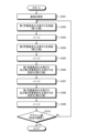
(一実施形態に係る成膜方法の流れの一例)
図1は、一実施形態に係る成膜方法の流れの一例を示すフローチャートである。一実施形態に係る成膜方法は、マイクロ波プラズマALD(Atomic Layer Deposition)法を用いて基板上にカーボン膜を形成する。図1においては、下地膜が形成された基板に対してカーボン膜としてグラフェン膜を成膜する場合を例に説明する。まず、下地膜が形成された基板を提供する(ステップS101)。例えば、下地膜が形成された半導体基板を処理容器(処理容器)に配置する。下地膜は、例えば、二酸化シリコン(SiO2)膜等の絶縁膜である。
(Example of Flow of Film Forming Method According to One Embodiment)
FIG. 1 is a flow chart showing an example of the flow of a film forming method according to an embodiment. In the film forming method according to an embodiment, a carbon film is formed on a substrate using a microwave plasma ALD (Atomic Layer Deposition) method. In FIG. 1, a case where a graphene film is formed as a carbon film on a substrate on which an underlayer film is formed is described as an example. First, a substrate on which an underlayer film is formed is provided (step S101). For example, a semiconductor substrate on which an underlayer film is formed is placed in a processing vessel. The underlayer film is, for example, an insulating film such as a silicon dioxide (SiO 2 ) film.
次に、基板に第1官能基を有する第1芳香族炭化水素ガスを供給する(ステップS102、第1工程)。第1官能基は、例えば、電子の偏り(例えば、非共有電子対)を有する官能基である。第1芳香族炭化水素ガスは、例えば、トルエン(C6H5CH3)、アニリン(C6H5NH2)及びジクロロベンゼン(C6H4Cl2)から選択される少なくとも1つの芳香族炭化水素ガスである。 Next, a first aromatic hydrocarbon gas having a first functional group is supplied to the substrate (step S102, first process). The first functional group is, for example, a functional group having an electron imbalance (for example, an unshared electron pair). The first aromatic hydrocarbon gas is, for example, at least one aromatic hydrocarbon gas selected from toluene (C6H5CH3), aniline (C6H5NH2), and dichlorobenzene (C6H4Cl2).
次に、処理容器をパージして、下地膜の表面上に過剰に吸着した第1芳香族炭化水素ガスの成分を排出する(ステップS103)。 Next, the processing vessel is purged to remove excess components of the first aromatic hydrocarbon gas adsorbed on the surface of the base film (step S103).
次に、少なくとも希ガスを含む第1反応ガスのプラズマにより下地膜の表面上に吸着した第1芳香族炭化水素ガスを活性化させて、下地膜の表面上にグラフェン膜を形成する(ステップS104、第2工程)。希ガスは、例えば、アルゴン(Ar)等である。第1反応ガスは、希ガスと炭素含有ガスとを含む混合ガスであってもよい。炭素含有ガスは、例えば、アセチレン(C2H2)等である。第1反応ガスは、さらに水素含有ガスが添加されてもよい。水素含有ガスは、例えば、水素(H2)等である。第1反応ガスのプラズマは、例えばマイクロ波や容量結合型などを用いて生成される。 Next, the first aromatic hydrocarbon gas adsorbed on the surface of the base film is activated by plasma of a first reactive gas containing at least a rare gas, to form a graphene film on the surface of the base film (step S104, second process). The rare gas is, for example, argon (Ar) or the like. The first reactive gas may be a mixed gas containing a rare gas and a carbon-containing gas. The carbon-containing gas is, for example, acetylene (C2H2) or the like. The first reactive gas may further contain a hydrogen-containing gas. The hydrogen-containing gas is, for example, hydrogen (H2) or the like. The plasma of the first reactive gas is generated using, for example, microwaves or a capacitively coupled type.
次に、処理容器をパージして、下地膜の表面上に過剰に吸着した第1反応ガスの成分を排出する(ステップS105)。次に、ステップS101~S105において下地膜の表面上に形成されたグラフェン膜が所定の膜厚に達したか否かを判定する(ステップS106)。グラフェン膜が所定の膜厚に達していないと判定した場合(ステップS106、No)、ステップS102に戻ってステップS105までを繰り返す。一方、グラフェン膜が所定の膜厚に達していると判定した場合(ステップS106、Yes)、処理を終了する。 Next, the processing vessel is purged to discharge the components of the first reaction gas that are excessively adsorbed on the surface of the base film (step S105). Next, it is determined whether or not the graphene film formed on the surface of the base film in steps S101 to S105 has reached a predetermined film thickness (step S106). If it is determined that the graphene film has not reached the predetermined film thickness (step S106, No), the process returns to step S102 and repeats up to step S105. On the other hand, if it is determined that the graphene film has reached the predetermined film thickness (step S106, Yes), the process ends.
図1に示す処理中、第1工程及び第2工程における基板の温度は、例えば25℃~550℃の範囲内に維持される。なお、ステップS103、S105のパージは省略してもよい。 During the process shown in FIG. 1, the temperature of the substrate in the first and second steps is maintained within a range of, for example, 25°C to 550°C. Note that the purging in steps S103 and S105 may be omitted.
また、ステップS106における判定は、例えば、ステップS102~S105を所定回数実行したか否かに基づいて行う。 The determination in step S106 is made, for example, based on whether steps S102 to S105 have been executed a predetermined number of times.
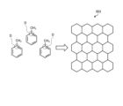
図2は、一実施形態に係る成膜方法により形成されるグラフェン膜の一例について説明するための図である。図2を参照して、一実施形態に係る成膜方法についてさらに説明する。 Figure 2 is a diagram for explaining an example of a graphene film formed by a film formation method according to one embodiment. The film formation method according to one embodiment will be further described with reference to Figure 2.
図2に示す基板Wは、半導体基板301上に形成された下地膜302を含む。まず、基板Wを処理容器内に配置する。次に、ステップS102で第1官能基を有する第1芳香族炭化水素ガスを基板Wに供給する。第1芳香族炭化水素ガスは、前駆体(プリカーサ)ガスとして下地膜302の表面上に吸着し、図2の(A)に示す層を形成する。処理容器のパージ後、ステップS104で少なくとも希ガスを含む第1反応ガスのプラズマを処理容器内に生成する。ステップS102及びステップS104における基板Wの温度は、例えば25℃~550℃の範囲内に維持される。第1反応ガスのプラズマにより、下地膜302の表面上において第1芳香族炭化水素ガスが活性化され、グラフェン膜303を形成する(図2の(B))。処理容器のパージ後、ステップS102~S105を繰り返すことにより、所望の膜厚のグラフェン膜303が形成される(図2の(C))。プラズマにより活性化される第1芳香族炭化水素ガスが第1官能基を有することで、下地膜302の表面上においてグラフェン膜303の成長が促進される。
The substrate W shown in FIG. 2 includes an
(グラフェン膜の成長促進のメカニズム)
図3は、一実施形態に係る成膜方法によるグラフェン膜の成長促進のメカニズムの一例について説明するための図である。図3を参照して、第1官能基を有する第1芳香族炭化水素ガスが用いられる場合にグラフェン膜303の成長が促進されるメカニズムについて説明する。図3の左側には、下地膜302の表面上に吸着した第1芳香族炭化水素ガスであるトルエン(C6H5CH3)の状態が示されている。第2工程において第1反応ガスのプラズマによりトルエンが活性化される場合(ステップS104)、活性化されたトルエンから第1官能基であるメチル基(CH3-)が脱離する。図3の左側には、メチル基が脱離する位置が脱離位置Dとして示されている。脱離位置Dにおいて、隣接するトルエンに含まれる炭素原子の六員環どうしの連結が開始される。すなわち、メチル基の脱離位置Dを起点としてC-C結合が形成される。そして、隣接するトルエンに含まれる炭素原子の六員環どうしがC-C結合により順次連結されることで、図3の右側に示すように、炭素原子の六員環を持つグラフェン膜303が下地膜302の表面上において成長する。脱離したメチル基はトルエン分子のC-H結合のH原子と結合してメタン分子となり、トルエン分子に新たな脱離位置を形成する。
(Mechanism of promoting graphene film growth)
FIG. 3 is a diagram for explaining an example of a mechanism for promoting the growth of a graphene film by a film forming method according to an embodiment. With reference to FIG. 3, a mechanism for promoting the growth of a
このように、プラズマにより活性化される第1芳香族炭化水素ガスが第1官能基を有する場合、グラフェン膜303の成長が促進される。結果として、基板Wの温度が25℃~550℃の範囲内に維持される低温環境下であっても、グラフェン膜303の成膜を効率化することができる。
In this way, when the first aromatic hydrocarbon gas activated by the plasma has the first functional group, the growth of the
また、第2工程では、第1反応ガスに炭素含有ガスを添加すると、炭素含有ガスは、グラフェン膜303が成長する際に炭素原子の六員環どうしを連結するボンド成分として寄与するため、グラフェン膜303の成膜を促進することができる。このため、第1反応ガスとして、希ガスと炭素含有ガスとを含む混合ガスが利用されてもよい。また、第2工程では、第1反応ガスに水素含有ガスを添加すると、水素含有ガスは、グラフェン膜303が成長する際に、グラフェン膜303に対してエッチング成分として寄与する。すなわち、水素含有ガスは、結合の不安定なC-C結合をエッチングしてグラフェン膜303の成長速度を調整することができる。このため、第1反応ガスは、水素含有ガスをさらに含んでもよい。
In addition, in the second step, when a carbon-containing gas is added to the first reactive gas, the carbon-containing gas contributes as a bond component that connects the six-membered rings of carbon atoms when the
(変形例1-二種のプリカーサの活性化)
上記実施形態では、単一のプリカーサ(つまり、第1芳香族炭化水素ガス)を活性化してグラフェン膜を形成する場合を説明した。実施形態はさらに変形可能である。図4は、変形例1に係る成膜方法の流れの一例を示すフローチャートである。変形例1は、二種のプリカーサを活性化してグラフェン膜を形成する。
(Variation 1 - Activation of Two Precursors)
In the above embodiment, a case has been described in which a graphene film is formed by activating a single precursor (i.e., a first aromatic hydrocarbon gas). The embodiment can be further modified. Fig. 4 is a flowchart showing an example of the flow of a film forming method according to
変形例1に係る成膜方法においては、基板Wの提供(ステップS201)から、パージ(ステップS203)までの処理は、それぞれ上記実施形態のステップS101~S103と同様である。変形例1では、ステップS203の後に、基板に第2官能基を有する第2芳香族炭化水素ガスを供給する(ステップS204、第3工程)。第2官能基は、例えば、電子の偏り(例えば、非共有電子対)を有する官能基である。第2芳香族炭化水素ガスは、例えば、トルエン(C6H5CH3)、アニリン(C6H5NH2)及びジクロロベンゼン(C6H4Cl2)から選択される少なくとも1つの芳香族炭化水素ガスであって、第1芳香族炭化水素ガスとは異なる芳香族炭化水素ガスである。第2芳香族炭化水素ガスは、第1芳香族炭化水素と同一の芳香族炭化水素ガスであってもよい。 In the film forming method according to the first modification, the processes from providing the substrate W (step S201) to purging (step S203) are the same as steps S101 to S103 in the above embodiment. In the first modification, after step S203, a second aromatic hydrocarbon gas having a second functional group is supplied to the substrate (step S204, third process). The second functional group is, for example, a functional group having an electron imbalance (for example, an unshared electron pair). The second aromatic hydrocarbon gas is, for example, at least one aromatic hydrocarbon gas selected from toluene (C6H5CH3), aniline (C6H5NH2), and dichlorobenzene (C6H4Cl2), and is an aromatic hydrocarbon gas different from the first aromatic hydrocarbon gas. The second aromatic hydrocarbon gas may be the same aromatic hydrocarbon gas as the first aromatic hydrocarbon gas.
次に、処理容器をパージして、下地膜の表面上に過剰に吸着した第2芳香族炭化水素ガスの成分を排出する(ステップS205)。 Next, the processing vessel is purged to remove excess components of the second aromatic hydrocarbon gas adsorbed on the surface of the base film (step S205).
次に、少なくとも希ガスを含む第1反応ガスのプラズマにより下地膜の表面上に吸着した第1芳香族炭化水素ガス及び第2芳香族炭化水素ガスを活性化させて、下地膜の表面上にグラフェン膜を形成する(ステップS206、第2工程)。希ガスは、例えば、アルゴン(Ar)等である。第1反応ガスは、さらに水素含有ガスが添加されてもよい。水素含有ガスは、例えば、水素(H2)等である。第1反応ガスのプラズマは、例えばマイクロ波や容量結合型などを用いて生成される。第2工程においては、活性化された第1芳香族炭化水素ガス及び第2芳香族炭化水素ガスから第1官能基及び第2官能基が脱離する位置を起点としてC-C結合が形成される。その後のパージ(ステップS207)からステップS208までの処理は、それぞれ上記実施形態のステップS105~S106と同様である。 Next, the first aromatic hydrocarbon gas and the second aromatic hydrocarbon gas adsorbed on the surface of the base film are activated by plasma of the first reactive gas containing at least a rare gas to form a graphene film on the surface of the base film (step S206, second process). The rare gas is, for example, argon (Ar) or the like. The first reactive gas may further contain a hydrogen-containing gas. The hydrogen-containing gas is, for example, hydrogen (H2) or the like. The plasma of the first reactive gas is generated, for example, by using microwaves or a capacitive coupling type. In the second process, a C-C bond is formed starting from the position where the first functional group and the second functional group are desorbed from the activated first aromatic hydrocarbon gas and the second aromatic hydrocarbon gas. The subsequent processes from purging (step S207) to step S208 are similar to steps S105 to S106 of the above embodiment, respectively.
このように、二種のプリカーサである第1芳香族炭化水素ガス及び第2芳香族炭化水素ガスを活性化してグラフェン膜を形成することにより、C-C結合が形成される起点となる位置を増やすことができる。結果として、グラフェン膜の成膜をより効率化することができる。 In this way, by activating the two precursors, the first aromatic hydrocarbon gas and the second aromatic hydrocarbon gas, to form a graphene film, it is possible to increase the number of positions that serve as the starting points for the formation of C-C bonds. As a result, it is possible to more efficiently form the graphene film.
(変形例2-段階的な活性化)
図5は、変形例2に係る成膜方法の流れの一例を示すフローチャートである。変形例2は、二種のプリカーサを段階的に活性化してグラフェン膜を形成する。
(Variation 2 - Stepwise activation)
5 is a flowchart showing an example of the flow of a film forming method according to
変形例2に係る成膜方法においては、基板Wの提供(ステップS301)から、パージ(ステップS307)までの処理は、それぞれ上記変形例1のステップS201~S207と同様である。変形例2では、吸着したガスの活性化(ステップS307)の後に、少なくとも希ガスを含む第2反応ガスのプラズマにより下地膜の表面上に吸着した第1芳香族炭化水素ガス及び第2芳香族炭化水素ガスをさらに活性化させる(ステップS308、第4工程)。希ガスは、例えば、アルゴン(Ar)等である。第2反応ガスは、希ガスと炭素含有ガスとを含む混合ガスであってもよい。炭素含有ガスは、例えば、アセチレン(C2H2)等である。第2反応ガスは、さらに水素含有ガスが添加されてもよい。水素含有ガスは、例えば、水素(H2)等である。第2反応ガスは、第1反応ガスとは異なるガスである。第2反応ガスは、第1反応ガスと同一のガスであってもよい。第2反応ガスのプラズマは、例えばマイクロ波を用いて生成される。 In the film forming method according to the second modification, the processes from providing the substrate W (step S301) to purging (step S307) are the same as steps S201 to S207 in the first modification. In the second modification, after activating the adsorbed gas (step S307), the first aromatic hydrocarbon gas and the second aromatic hydrocarbon gas adsorbed on the surface of the base film are further activated by plasma of a second reactive gas containing at least a rare gas (step S308, fourth process). The rare gas is, for example, argon (Ar) or the like. The second reactive gas may be a mixed gas containing a rare gas and a carbon-containing gas. The carbon-containing gas is, for example, acetylene (C2H2) or the like. The second reactive gas may further contain a hydrogen-containing gas. The hydrogen-containing gas is, for example, hydrogen (H2) or the like. The second reactive gas is a gas different from the first reactive gas. The second reactive gas may be the same gas as the first reactive gas. The plasma of the second reactive gas is generated, for example, by using microwaves.
次に、処理容器をパージして、下地膜の表面上に過剰に吸着した第2反応ガスの成分を排出する(ステップS309)。その後のステップS310は、上記変形例2のステップS208と同様である。 Next, the processing vessel is purged to remove excess second reaction gas components adsorbed on the surface of the base film (step S309). The subsequent step S310 is the same as step S208 in the above-described modification example 2.
このように、二種のプリカーサである第1芳香族炭化水素ガス及び第2芳香族炭化水素ガスを第1反応ガス及び第2反応ガスのプラズマにより段階的に活性化してグラフェン膜を形成することにより、グラフェン膜の不安定なC-C結合を補強することができる。結果として、グラフェン膜の構造を安定化することができる。 In this way, the graphene film is formed by gradually activating the two precursors, the first aromatic hydrocarbon gas and the second aromatic hydrocarbon gas, with the plasma of the first reactive gas and the second reactive gas, thereby reinforcing the unstable C-C bonds in the graphene film. As a result, the structure of the graphene film can be stabilized.
(変形例3-吸着サイトの形成)
図6は、変形例3に係る成膜方法の流れの一例を示すフローチャートである。変形例3は、プリカーサの供給(第1工程)の前に、プリカーサを吸着可能な吸着サイトを下地膜の表面上に形成する。
(Modification 3: Formation of Adsorption Sites)
6 is a flowchart showing an example of the flow of a film forming method according to Modification 3. In Modification 3, before the supply of a precursor (first step), adsorption sites capable of adsorbing the precursor are formed on the surface of an undercoat film.
変形例3に係る成膜方法においては、基板Wの提供(ステップS401)の後に、基板Wに極性を持つ分子ガス、たとえば窒素含有ガスを供給して、プリカーサである第1芳香族炭化水素ガスを吸着可能な吸着サイトを下地膜の表面上に形成する(ステップS402、第5工程)。次に、処理容器をパージして、下地膜の表面上に過剰に吸着した窒素含有ガスの成分を排出する(ステップS403)。その後の第1芳香族炭化水素ガスの供給(ステップS404)からステップS408までの処理は、それぞれ上記実施形態のステップS102~S106と同様である。 In the film forming method according to the third modified example, after providing the substrate W (step S401), a polar molecular gas, for example, a nitrogen-containing gas, is supplied to the substrate W to form adsorption sites on the surface of the base film capable of adsorbing the precursor first aromatic hydrocarbon gas (step S402, fifth process). Next, the processing vessel is purged to discharge the components of the nitrogen-containing gas that are excessively adsorbed on the surface of the base film (step S403). The subsequent processes from supplying the first aromatic hydrocarbon gas (step S404) to step S408 are similar to steps S102 to S106 of the above embodiment.
このように、プリカーサの供給の前に、吸着サイトを下地膜の表面上に形成することにより、下地膜の表面に対するプリカーサの吸着量を増やすことができる。結果として、下地膜の表面上に吸着したプリカーサの活性化を経てグラフェン膜を安定的に成膜することができる。 In this way, by forming adsorption sites on the surface of the base film before the precursor is supplied, the amount of precursor adsorbed to the surface of the base film can be increased. As a result, a graphene film can be stably formed through activation of the precursor adsorbed on the surface of the base film.
なお、上記変形例3では、プリカーサの供給(第1工程)の前に、窒素含有ガスの供給(ステップS402、第5工程)を行う例を示したが、第1工程及び第2工程の繰り返しが完了するたびに第5工程が実行されるようにしてもよい。
In the above modification example 3, an example is shown in which the nitrogen-containing gas is supplied (step S402, step 5) before the precursor is supplied (step 1), but step 5 may be performed each time the repetition of
(実験結果-グラフェン膜の成長の有無)
次に、異なる下地膜が形成された3つの基板Wの各々に対して第2工程におけるプラズマをマイクロ波プラズマ又は容量結合型プラズマとした変形例1に係る成膜方法(図4参照)を適用した場合のグラフェン膜の成長の有無について実験を行った。実験では、下地膜として、SiO2膜、Cu膜又はCo膜を有する3つの基板Wが用いられた。また、実験では、変形例1に係る成膜方法の第1~第3工程の各工程は、以下の処理条件で行われた。
マイクロ波プラズマによるグラフェン成膜:
<第1工程>
処理容器内の圧力:1Torr(133Pa)
処理ガス :1,3-ジクロロベンゼン=10sccm
基板Wの温度 :350℃
処理時間 :5秒
<第3工程>
処理容器内の圧力:1Torr(133Pa)
処理ガス :アニリン=10sccm
基板Wの温度 :350℃
処理時間 :5秒
<第2工程>
マイクロ波電力 :400W
処理容器内の圧力:1Torr(133Pa)
処理ガス :Ar=500sccm
基板Wの温度 :350℃
処理時間 :5秒
容量結合型プラズマによるグラフェン成膜:
<第1工程>
処理容器内の圧力:3Torr(400Pa)
処理ガス :トルエン=10sccm
基板Wの温度 :350℃
処理時間 :5秒
<第2工程>
プラズマ電力 :50W(13.56MHz)
処理容器内の圧力:3Torr(400Pa)
処理ガス :Ar=500sccm
基板Wの温度 :350℃
処理時間 :5秒
(Experimental results - whether or not graphene film grows)
Next, an experiment was conducted on the presence or absence of growth of a graphene film when the film formation method according to the first modification (see FIG. 4 ), in which the plasma in the second step was microwave plasma or capacitively coupled plasma, was applied to each of three substrates W on which different undercoat films were formed. In the experiment, three substrates W having a SiO2 film, a Cu film, or a Co film as the undercoat film were used. In the experiment, each of the first to third steps of the film formation method according to the first modification was performed under the following processing conditions.
Graphene deposition using microwave plasma:
<First step>
Pressure in processing vessel: 1 Torr (133 Pa)
Processing gas: 1,3-dichlorobenzene = 10 sccm
Temperature of substrate W: 350° C.
Processing time: 5 seconds <Third step>
Pressure in processing vessel: 1 Torr (133 Pa)
Processing gas: aniline = 10 sccm
Temperature of substrate W: 350° C.
Processing time: 5 seconds <Second step>
Microwave power: 400W
Pressure in processing vessel: 1 Torr (133 Pa)
Processing gas: Ar = 500 sccm
Temperature of substrate W: 350° C.
Processing time: 5 seconds Graphene deposition using capacitively coupled plasma:
<First step>
Pressure in processing vessel: 3 Torr (400 Pa)
Processing gas: toluene = 10 sccm
Temperature of substrate W: 350° C.
Processing time: 5 seconds <Second step>
Plasma power: 50W (13.56MHz)
Pressure in processing vessel: 3 Torr (400 Pa)
Processing gas: Ar = 500 sccm
Temperature of substrate W: 350° C.
Processing time: 5 seconds
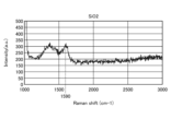
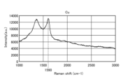
図7および図10は、SiO2膜を有する基板Wに対して変形例1の成膜方法を適用した場合のSiO2膜の表面上におけるラマンスペクトルの分布の一例を示す図である。図8および図11は、Cu膜を有する基板Wに対して変形例1の成膜方法を適用した場合のCu膜の表面上におけるラマンスペクトルの分布の一例を示す図である。図9および図12は、Co膜を有する基板Wに対して変形例1の成膜方法を適用した場合のCo膜の表面上におけるラマンスペクトルの分布の一例を示す図である。ラマンスペクトルの分布においては、グラフェン膜が存在する場合に、グラフェン膜に含まれる炭素原子の六員環構造の面内振動に起因して、Gバンドと呼ばれるピークが出現することが知られている。Gバンドは、ラマンスペクトルの1590cm-1近傍の位置に出現する。Gバンドの出現は、グラフェン膜が存在することを示す。 7 and 10 are diagrams showing an example of the distribution of the Raman spectrum on the surface of a SiO2 film when the film forming method of the modified example 1 is applied to a substrate W having a SiO2 film. FIG. 8 and FIG. 11 are diagrams showing an example of the distribution of the Raman spectrum on the surface of a Cu film when the film forming method of the modified example 1 is applied to a substrate W having a Cu film. FIG. 9 and FIG. 12 are diagrams showing an example of the distribution of the Raman spectrum on the surface of a Co film when the film forming method of the modified example 1 is applied to a substrate W having a Co film. It is known that in the distribution of the Raman spectrum, when a graphene film is present, a peak called a G band appears due to the in-plane vibration of the six-membered ring structure of the carbon atoms contained in the graphene film. The G band appears at a position near 1590 cm −1 in the Raman spectrum. The appearance of the G band indicates the presence of a graphene film.
図7~図12に示すように、下地膜としてSiO2膜、Cu膜又はCo膜を有する3つの基板Wのいずれが用いられる場合でも、Gバンドの出現が確認された。すなわち、図7~図12の実験結果は、変形例1に係る成膜方法によれば、下地膜の種別に関わらずグラフェン膜を成長させることができることを示している。
As shown in Figures 7 to 12, the appearance of the G band was confirmed when any of the three substrates W having a SiO2 film, a Cu film, or a Co film as the underlayer was used. In other words, the experimental results in Figures 7 to 12 show that the film formation method of
図13は、SiO2膜を有する基板Wに対して第2工程におけるプラズマをマイクロ波プラズマとした変形例1の成膜方法を適用した場合の基板Wの断面の一例を示すTEM写真である。図13に示す基板Wは、シリコン(Si)基板332と下地膜としてのSiO2膜332aとを備えている。SiO2膜332aは、例えば自然酸化膜である。基板Wに対して第2工程におけるプラズマをマイクロ波プラズマとした変形例1の成膜方法を適用した場合、SiO2膜332aの表面上にグラフェン膜333が形成されていることが確認された。微細なパターンやアスペクト比が高いパターンを有する下地膜へグラフェン膜を形成する場合、CVD法ではパターン頂部とパターン開口部近傍で原料(プリカーサ)が消費されてしまい、パターン頂部とパターン開口部近傍には成膜できるが、パターンの奥側にあたるパターン側壁と底部には成膜できないことが課題である。この課題を解決する手段として、パターンを有する下地膜の表面に原料を飽和吸着させて成膜するALD法にすることで、パターンを有する下地膜全面に対してグラフェン成膜を行うことができる。
Figure 13 is a TEM photograph showing an example of a cross section of a substrate W having a SiO2 film when the film formation method of
(パターンを有する下地膜が形成された基板Wへの応用)
次に、パターンを有する下地膜が形成された基板Wに対して第2工程におけるプラズマをマイクロ波プラズマとした変形例1の成膜方法を適用する例について説明する。図14は、第2工程におけるプラズマをマイクロ波プラズマとした変形例1の成膜方法が適用される基板Wの断面の一例を示す図である。図14に示す基板Wは、半導体基板351上に形成された下地膜352を含む。下地膜352には、頂部T1、側壁T2及び底部T3を有するパターンが形成されている。図14に示す基板Wに第2工程におけるプラズマをマイクロ波プラズマとした変形例1の成膜方法を適用することにより、下地膜352のパターンの表面上にコンフォーマルなグラフェン膜が形成される。ここで、第2工程におけるプラズマをマイクロ波プラズマとした変形例1に係る成膜方法の第1~第3工程の各工程は、上記実験と同様の処理条件で行われた。
(Application to a substrate W on which a patterned undercoat film is formed)
Next, an example of applying the film formation method of the first modification in which the plasma in the second step is microwave plasma to a substrate W on which a patterned undercoat film is formed will be described. FIG. 14 is a diagram showing an example of a cross section of a substrate W to which the film formation method of the first modification in which the plasma in the second step is microwave plasma is applied. The substrate W shown in FIG. 14 includes an
図15Aは、パターンを有する下地膜352が形成された基板Wに対して第2工程におけるプラズマをマイクロ波プラズマとした変形例1の成膜方法を適用した場合の基板Wの断面の一例を示すTEM写真である。基板Wに対して第2工程におけるプラズマをマイクロ波プラズマとした変形例1の成膜方法を適用した場合、パターンの頂部T1、側壁T2及び底部T3の表面上にグラフェン膜353が形成されていることが確認された。すなわち、図15AのTEM写真は、変形例1の成膜方法によれば、下地膜352のパターンに対するステップカバレッジを改善することができることを示している。
Figure 15A is a TEM photograph showing an example of a cross section of a substrate W on which a patterned
これに対して、パターンを有する下地膜が形成された基板Wに対して比較例の成膜方法を適用する例について説明する。比較例の成膜方法では、マイクロ波プラズマCVD法を用いて、基板上にカーボン膜であるグラフェン膜を形成する。変形例の成膜方法が適用される基板は、図14に示す基板Wと同様の構造を有する。ここで、比較例の成膜方法は、前処理工程と成膜工程とを含み、各工程は、以下の処理条件で行われた。
<前処理工程>
マイクロ波電力 :2000W
処理容器内の圧力:3Torr(399Pa)
処理ガス :H2/Ar=50/1000sccm
基板Wの温度 :400℃
処理時間 :600秒
<成膜工程>
マイクロ波電力 :2000W
処理容器内の圧力:0.01Torr(1.33Pa)
処理ガス :C2H4/Ar=20/500sccm
基板Wの温度 :400℃
処理時間 :180秒
In contrast, an example will be described in which a film formation method of a comparative example is applied to a substrate W on which a base film having a pattern is formed. In the film formation method of the comparative example, a graphene film, which is a carbon film, is formed on a substrate by using a microwave plasma CVD method. The substrate to which the film formation method of the modified example is applied has a structure similar to that of the substrate W shown in FIG. 14. Here, the film formation method of the comparative example includes a pretreatment process and a film formation process, and each process is performed under the following processing conditions.
<Pretreatment process>
Microwave power: 2000W
Pressure in processing vessel: 3 Torr (399 Pa)
Processing gas: H2/Ar=50/1000 sccm
Temperature of substrate W: 400° C.
Processing time: 600 seconds <Film formation process>
Microwave power: 2000W
Pressure in processing vessel: 0.01 Torr (1.33 Pa)
Processing gas: C2H4/Ar=20/500 sccm
Temperature of substrate W: 400° C.
Processing time: 180 seconds
図15Bは、パターンを有する下地膜352が形成された基板Wに対して比較例の成膜方法を適用した場合の基板Wの断面の一例を示すTEM写真である。基板Wに対して変形例の成膜方法を適用した場合、パターンの頂部T1と頂部T1によって囲まれる開口近傍とにのみグラフェン膜354が形成され、側壁T2及び底部T3にはグラフェン膜が形成されないことが確認された。すなわち、図15BのTEM写真は、マイクロ波プラズマCVD法を用いる比較例の成膜方法では、下地膜352のパターンに対するステップカバレッジが劣化してしまうことを示している。
Figure 15B is a TEM photograph showing an example of a cross section of a substrate W on which a patterned
次に、パターンを有する下地膜352が形成された基板Wに対して第2工程におけるプラズマを容量結合型プラズマとした一実施形態の成膜方法を適用する例について説明する。具体的には、図14に示すパターンが形成された基板Wに第2工程におけるプラズマを容量結合型プラズマとした一実施形態の成膜方法を適用した実験を行った。
Next, an example will be described in which the film formation method of one embodiment in which the plasma in the second step is capacitively coupled plasma is applied to a substrate W on which a patterned
図16は、パターンを有する下地膜352が形成された基板Wに対して第2工程におけるプラズマを容量結合型プラズマとした一実施形態の成膜方法を適用した場合の基板Wの断面の一例を示すSEM写真である。基板Wに対して第2工程におけるプラズマを容量結合型プラズマとした一実施形態の成膜方法を適用した場合、パターンの頂部T1、側壁T2及び底部T3の表面上にグラフェン膜354が形成されていることが確認された。すなわち、図16のSEM写真は、一実施形態の成膜方法によれば、下地膜352のパターンに対するステップカバレッジを改善することができることを示している。
Figure 16 is an SEM photograph showing an example of a cross section of a substrate W on which a patterned
(一実施形態に係る成膜装置の一例)
図17は、一実施形態に係る成膜方法の実行に用いられる成膜装置の一例を示す図である。図17に示す成膜装置100は、処理容器101と、載置台102と、ガス供給機構103と、排気装置104と、マイクロ波導入装置105と、制御部106とを有する。処理容器101は、基板Wを収容する。載置台102は、基板Wを載置する。ガス供給機構103は、処理容器101内にガスを供給する。排気装置104は、処理容器101内を排気する。マイクロ波導入装置105は、処理容器101内にプラズマを生成させるためのマイクロ波を発生させるとともに、処理容器101内にマイクロ波を導入する。制御部106は、成膜装置100の各部の動作を制御する。
(An example of a film forming apparatus according to an embodiment)
17 is a diagram showing an example of a film forming apparatus used to perform a film forming method according to an embodiment. The
処理容器101は、例えばアルミニウムおよびその合金等の金属材料によって形成され、略円筒形状をなしており、板状の天壁部111および底壁部113と、これらを連結する側壁部112とを有している。マイクロ波導入装置105は、処理容器101の上部に設けられ、処理容器101内に電磁波(マイクロ波)を導入してプラズマを生成するプラズマ生成手段として機能する。マイクロ波導入装置105については後で詳細に説明する。
The
天壁部111には、マイクロ波導入装置105の後述するマイクロ波放射機構およびガス導入部が嵌め込まれる複数の開口部を有している。側壁部112は、処理容器101に隣接する搬送室(図示せず)との間で被処理基板である基板Wの搬入出を行うための搬入出口114を有している。搬入出口114はゲートバルブ115により開閉されるようになっている。底壁部113には排気装置104が設けられている。排気装置104は底壁部113に接続された排気管116に設けられ、真空ポンプと圧力制御バルブを備えている。排気装置104の真空ポンプにより排気管116を介して処理容器101内が排気される。処理容器101内の圧力は圧力制御バルブにより制御される。
The
載置台102は、円板状をなしており、AlN等のセラミックスからなっている。載置台102は、処理容器101の底部中央から上方に延びる円筒状のAlN等のセラミックスからなる支持部材120により支持されている。載置台102の外縁部には基板Wをガイドするためのガイドリング181が設けられている。また、載置台102の内部には、基板Wを昇降するための昇降ピン(図示せず)が載置台102の上面に対して突没可能に設けられている。さらに、載置台102の内部には抵抗加熱型のヒータ182が埋め込まれており、このヒータ182はヒータ電源183から給電されることにより載置台102を介してその上の基板Wを加熱する。また、載置台102には、熱電対(図示せず)が挿入されており、熱電対からの信号に基づいて、基板Wの加熱温度を、例えば25~1000℃の範囲の所定の温度に制御可能となっている。さらに、載置台102内のヒータ182の上方には、基板Wと同程度の大きさの電極184が埋設されており、この電極184には、高周波バイアス電源122が電気的に接続されている。この高周波バイアス電源122から載置台102に、イオンを引き込むための高周波バイアスが印加される。なお、高周波バイアス電源122はプラズマ処理の特性によっては設けなくてもよい。
The mounting table 102 is disk-shaped and made of ceramics such as AlN. The mounting table 102 is supported by a
ガス供給機構103は、プラズマ生成用の反応ガス、およびカーボン膜(グラフェン膜)を形成するためのプリカーサガスを処理容器101内に導入するためのものであり、複数のガス導入ノズル123を有している。ガス導入ノズル123は、処理容器101の天壁部111に形成された開口部に嵌め込まれている。ガス導入ノズル123には、ガス供給配管191が接続されている。このガス供給配管191は、分岐管191a、191b、191c、191d、191eの5つに分岐している。これら分岐管191a、191b、191c、191d、191eには、ガス供給源192、193、194、195、196、197が接続されている。ガス供給源192は、グラフェン膜のプリカーサガスである芳香族炭化水素ガスとしてのトルエン(C6H5CH3)を供給する。ガス供給源193は、グラフェン膜のプリカーサガスである芳香族炭化水素ガスとしてのアニリン(C6H5NH2)を供給する。ガス供給源194は、グラフェン膜のプリカーサガスである芳香族炭化水素ガスとしてのジクロロベンゼン(C6H4Cl2)を供給する。ガス供給源195は、プラズマ生成用の反応ガスである希ガスとしてのアルゴン(Ar)を供給する。ガス供給源196は、還元性ガスとしての水素(H2)を供給する。ガス供給源197は、パージガスや、吸着サイト形成用のガスとして用いられる窒素含有ガスとしての窒素(N2)またはアンモニア(NH3)を供給する。ガス供給源198は、ボンド成分として寄与する炭素含有ガスとしてのアセチレン(C2H2)を供給する。ガス供給源193~195が供給する芳香族炭化水素ガスは、第1芳香族炭化水素ガス及び第2芳香族炭化水素ガスの一例である。また、ガス供給源195が供給する希ガスは、第1反応ガス及び第2反応ガスの一例である。
The
なお、分岐管191a、191b、191c、191d、191eには、図示してはいないが、流量制御用のマスフローコントローラおよびその前後のバルブが設けられている。なお、シャワープレートを設けてC2H2ガスおよびH2ガスを基板Wに近い位置に供給するようにしてガスの解離を調整することもできる。また、これらのガスを供給するノズルを下方に延ばすことにより同様の効果を得ることができる。
Although not shown, the
マイクロ波導入装置105は、前述のように、処理容器101の上方に設けられ、処理容器101内に電磁波(マイクロ波)を導入してプラズマを生成するプラズマ生成手段として機能する。マイクロ波導入装置105は、処理容器101の天壁部111と、マイクロ波出力部130と、アンテナユニット140とを有する。天壁部111は、天板として機能する。マイクロ波出力部130は、マイクロ波を生成するとともに、マイクロ波を複数の経路に分配して出力する。マイクロ波の周波数は、例えば、860MHz、2.45GHz、8.35GHz、5.8GHz、1.98GHz等、700MHzから10GHzの範囲のものを用いることができる。アンテナユニット140は、マイクロ波出力部130から出力されたマイクロ波を処理容器101に導入する。
As described above, the
アンテナユニット140は、複数の(図17の例では3つの)アンテナモジュールを含んでいる。複数のアンテナモジュールは、それぞれ、マイクロ波出力部130によって分配されたマイクロ波を処理容器101内に導入する。複数のアンテナモジュールの構成は全て同一である。各アンテナモジュールは、分配されたマイクロ波を主に増幅して出力するアンプ部142と、アンプ部142から出力されたマイクロ波を処理容器101内に放射するマイクロ波放射機構143とを有する。
The
制御部106は、プロセッサ、記憶部、入出力装置等を備えるコンピュータであり、成膜装置100の各部を制御する。
The
制御部106は、一実施形態に係る成膜方法の各工程において成膜装置100の各部を制御するためのコンピュータプログラム(例えば、入力されたレシピに基づくプログラム)に従って動作し、制御信号を送出する。成膜装置100の各部は、制御部106からの制御信号によって制御される。具体的には、制御部106は、図13に示す成膜装置100において、制御信号を用いて、ガス供給部192等から供給されるガスの選択及び流量、排気装置104の排気、マイクロ波出力部130からのマイクロ波出力、等を制御することが可能である。なお、本明細書において開示される成膜方法の各工程は、制御部106による制御によって成膜装置100の各部を動作させることによって実行され得る。制御部106の記憶部には、一実施形態に係る成膜方法を実行するためのコンピュータプログラム及び当該成膜方法の実行に用いられる各種のデータが、読み出し自在に格納されている。
The
(一実施形態に係る成膜装置の他の一例)
図18は、一実施形態に係る成膜方法の実行に用いられる成膜装置の他の一例を示す図である。図18に示す成膜装置200は、略円筒状の処理容器1を有する。処理容器1の内部には、サセプタ2が、その中央下部に設けられた円筒状の支持部材3により支持された状態で配置される。このサセプタ2は、基板Wを水平に支持するための載置台(ステージ)であり、たとえば窒化アルミニウム(AlN)等のセラミックス材料や、アルミニウムやニッケル合金等の金属材料で構成される。
(Another Example of a Film Forming Apparatus According to an Embodiment)
Fig. 18 is a diagram showing another example of a film formation apparatus used to perform a film formation method according to an embodiment. The
サセプタ2の外縁部には、基板Wをガイドするためのガイドリング4が設けられる。また、サセプタ2には、モリブデンなどの高融点金属で構成されたヒータ5が埋め込まれる。このヒータ5は、ヒータ電源6から給電されることで、サセプタ2に支持された基板Wを所定の温度に加熱する。
A
処理容器1の天壁1aには、絶縁部材9を介してシャワーヘッド10が設けられる。シャワーヘッド10は、プリミックスタイプのシャワーヘッドであり、ベース部材11と、シャワープレート12とを有する。
A
そして、シャワーヘッド10におけるシャワープレート12の外周部が、貼り付き防止用の円環状をなす中間部材13を介して、ベース部材11に固定される。
The outer periphery of the
シャワープレート12は、フランジ状をなし、シャワープレート12の内部には、凹部が形成される。すなわち、ベース部材11とシャワープレート12との間には、ガス拡散空間14が形成される。ベース部材11の外周部にはフランジ部11aが形成され、このフランジ部11aが絶縁部材9に支持される。
The
また、シャワープレート12には、複数のガス吐出孔15が形成され、ベース部材11の中央付近には、1つのガス導入孔16が形成される。かかるガス導入孔16は、ガス供給機構20のガスラインに接続される。
The
ガス供給機構20は、ガス供給源21~27を有する。ガス供給源21は、グラフェン膜のプリカーサガスである芳香族炭化水素ガスとしてのトルエン(C6H5CH3)を供給する。ガス供給源22は、グラフェン膜のプリカーサガスである芳香族炭化水素ガスとしてのアニリン(C6H5NH2)を供給する。ガス供給源23は、グラフェン膜のプリカーサガスである芳香族炭化水素ガスとしてのジクロロベンゼン(C6H4Cl2)を供給する。ガス供給源24は、プラズマ生成用の反応ガスである希ガスとしてのアルゴン(Ar)を供給する。ガス供給源25は、還元性ガスとしての水素(H2)を供給する。ガス供給源26は、パージガスや、吸着サイト形成用のガスとして用いられる窒素含有ガスとしての窒素(N2)または、アンモニア(NH3)を供給する。ガス供給源27は、C-C結合のボンド成分として寄与する炭素含有ガスとしてのアセチレン(C2H2)を供給する。
The
ガス供給源21~27には、それぞれガス供給ライン29a~29gが接続される。そして、各ガスラインには、マスフローコントローラ(MFC)28aを挟んで2つのバルブ28bが設けられる。各ガスラインは、ガス配管30を介してガス導入孔16に接続される。そして、ガス導入孔16に供給されたガスは、ガス導入孔16を経てガス拡散空間14に至り、シャワープレート12のガス吐出孔15を通って処理容器1内の基板Wに向けて吐出される。
シャワーヘッド10には、整合器44を介して高周波電源45が接続される。高周波電源45は、シャワーヘッド10にプラズマ生成用の高周波電力を供給する。シャワーヘッド10は、平行平板電極の上部電極としても機能する。
A high-
一方、サセプタ2は、平行平板電極の下部電極として機能する。サセプタ2は、伝送路43を介して接地される。
On the other hand, the
また、シャワーヘッド10のベース部材11には、ヒータ47が設けられる。ヒータ47は、ヒータ電源48から給電されることで、シャワーヘッド10を所望の温度に加熱する。なお、ベース部材11の上部に形成された凹部には、断熱部材49が設けられる。
A
処理容器1の底壁1bにおける中央部には、円形の穴50が形成される。また、底壁1bには、この穴50を覆うように下方に向けて突出する排気室51が設けられる。排気室51の側面には排気管52が接続され、この排気管52には排気装置53が接続される。
A
そして、かかる排気装置53を動作させることで、処理容器1内を所定の真空度まで減圧することができる。
The
サセプタ2には、基板Wを支持して昇降させるための複数(たとえば、3本)の支持ピン54が設けられる。複数の支持ピン54は、サセプタ2の表面に対して突没可能に設けられ、支持板55に支持される。そして、支持ピン54は、駆動機構56により、支持板55を介して昇降可能に構成される。
The
処理容器1の側壁には、処理容器1と隣接して設けられた図示しない搬送室との間で基板Wの搬入出を行うための搬入出口57と、この搬入出口57を開閉するゲートバルブ58とが設けられる。
A loading/unloading
また、成膜装置200は、制御部61を備える。制御部61は、プロセッサ、記憶部、入出力装置等を備えるコンピュータであり、成膜装置200の各部を制御する。
The
制御部61は、一実施形態に係る成膜方法の各工程において成膜装置200の各部を制御するためのコンピュータプログラム(例えば、入力されたレシピに基づくプログラム)に従って動作し、制御信号を送出する。成膜装置200の各部は、制御部61からの制御信号によって制御される。具体的には、制御部61は、図14に示す成膜装置200において、制御信号を用いて、ガス供給源21等から供給されるガスの選択及び流量、排気装置53の排気、高周波電源45からの電力供給、等を制御することが可能である。なお、本明細書において開示される成膜方法の各工程は、制御部106による制御によって成膜装置200の各部を動作させることによって実行され得る。制御部106の記憶部には、一実施形態に係る成膜方法を実行するためのコンピュータプログラム及び当該成膜方法の実行に用いられる各種のデータが、読み出し自在に格納されている。
The
(実施形態の効果)
上記実施形態に係る成膜方法は、第1工程と第2工程とを含む。第1工程は、下地膜が形成された基板に第1官能基を有する第1芳香族炭化水素ガスを供給する。第2工程は、少なくとも希ガスを含む第1反応ガスのプラズマにより、下地膜の表面上に吸着した第1芳香族炭化水素ガスを活性化させる。このため、実施形態によれば、低温環境下であっても、カーボン膜(グラフェン膜)の成膜を効率化することができる。
(Effects of the embodiment)
The film forming method according to the embodiment includes a first step and a second step. In the first step, a first aromatic hydrocarbon gas having a first functional group is supplied to a substrate on which an undercoat film has been formed. In the second step, the first aromatic hydrocarbon gas adsorbed on the surface of the undercoat film is activated by plasma of a first reactive gas containing at least a rare gas. Therefore, according to the embodiment, it is possible to efficiently form a carbon film (graphene film) even in a low-temperature environment.
また、実施形態に係る成膜方法は、第2工程において、活性化された第1芳香族炭化水素ガスから第1官能基が脱離する位置を起点としてC-C結合が形成される。このため、実施形態によれば、官能基の脱離を契機として、第1芳香族炭化水素ガスに含まれる炭素原子の六員環どうしの連結を開始することができる。 In addition, in the film forming method according to the embodiment, in the second step, a C-C bond is formed starting from the position where the first functional group is detached from the activated first aromatic hydrocarbon gas. Therefore, according to the embodiment, the detachment of the functional group can be used as a trigger to start linking the six-membered rings of carbon atoms contained in the first aromatic hydrocarbon gas.
また、実施形態に係る成膜方法において、第1工程及び前記第2工程は、所定回数繰り返し実行される。このため、実施形態によれば、1回の処理でカーボン膜(グラフェン膜)の膜厚が所望の膜厚に達しない場合でも繰り返し処理を実行して所望の膜厚を実現することができる。 In addition, in the film forming method according to the embodiment, the first step and the second step are repeatedly performed a predetermined number of times. Therefore, according to the embodiment, even if the thickness of the carbon film (graphene film) does not reach the desired thickness in one process, the process can be repeated to achieve the desired thickness.
また、実施形態に係る成膜方法において、第1芳香族炭化水素ガスは、トルエン、アニリン及びジクロロベンゼンから選択される少なくとも1つの芳香族炭化水素ガスである。このため、実施形態によれば、単一の芳香族炭化水素ガスに含まれる炭素原子の六員環どうしを連結させて、カーボン膜(グラフェン膜)の成長を促進することができる。 In the film forming method according to the embodiment, the first aromatic hydrocarbon gas is at least one aromatic hydrocarbon gas selected from toluene, aniline, and dichlorobenzene. Therefore, according to the embodiment, the six-membered rings of carbon atoms contained in a single aromatic hydrocarbon gas can be linked together to promote the growth of a carbon film (graphene film).
また、実施形態に係る成膜方法において、第1反応ガスは、希ガスと炭素含有ガスとを含むガスであってもよい。このため、実施形態によれば、炭素含有ガスを炭素原子の六員環どうしを連結するボンド成分として利用することができる。 In the film forming method according to the embodiment, the first reactive gas may be a gas containing a rare gas and a carbon-containing gas. Therefore, according to the embodiment, the carbon-containing gas can be used as a bond component that connects the six-membered rings of carbon atoms.
また、実施形態に係る成膜方法において、第1反応ガスは、水素含有ガスをさらに含んでもよい。このため、実施形態によれば、水素含有ガスをカーボン膜(グラフェン膜)に対するエッチング成分として利用することができ、カーボン膜(グラフェン膜)の成長速度を調整することができる。 In the film forming method according to the embodiment, the first reactive gas may further contain a hydrogen-containing gas. Therefore, according to the embodiment, the hydrogen-containing gas can be used as an etching component for the carbon film (graphene film), and the growth rate of the carbon film (graphene film) can be adjusted.
また、実施形態に係る成膜方法は、第1工程後であって第2工程前の基板に対して第2官能基を有する第2芳香族炭化水素ガスを供給する第3工程をさらに含む。そして、第2工程は、第1反応ガスのプラズマにより下地膜の表面上に吸着した第1芳香族炭化水素ガス及び第2芳香族炭化水素ガスを活性化させる。このため、実施形態によれば、C-C結合が形成される起点となる位置を増やすことができ、結果として、グラフェン膜の成膜をより効率化することができる。 The film formation method according to the embodiment further includes a third step of supplying a second aromatic hydrocarbon gas having a second functional group to the substrate after the first step and before the second step. The second step activates the first aromatic hydrocarbon gas and the second aromatic hydrocarbon gas adsorbed on the surface of the base film by plasma of the first reactive gas. Therefore, according to the embodiment, it is possible to increase the number of positions that serve as starting points for the formation of C-C bonds, and as a result, it is possible to more efficiently form the graphene film.
また、実施形態に係る成膜方法は、第2工程において、活性化された第1芳香族炭化水素ガス及び第2芳香族炭化水素ガスから第1官能基及び第2官能基が脱離する位置を起点としてC-C結合が形成されてもよい。このため、実施形態によれば、官能基の脱離を契機として、第1芳香族炭化水素ガス及び第2芳香族炭化水素ガスに含まれる炭素原子の六員環どうしの連結を開始することができる。 In addition, in the film forming method according to the embodiment, in the second step, a C-C bond may be formed starting from the position where the first functional group and the second functional group are detached from the activated first aromatic hydrocarbon gas and the second aromatic hydrocarbon gas. Therefore, according to the embodiment, the detachment of the functional group can be used as a trigger to start linking the six-membered rings of carbon atoms contained in the first aromatic hydrocarbon gas and the second aromatic hydrocarbon gas.
また、実施形態に係る成膜方法は、第2芳香族炭化水素ガスは、トルエン、アニリン及びジクロロベンゼンから選択される少なくとも1つの芳香族炭素ガスであって、前記第1芳香族炭化水素ガスとは異なる芳香族炭化水素ガスであってもよい。このため、実施形態によれば、二種の芳香族炭化水素ガスに含まれる炭素原子の六員環どうしを連結させて、カーボン膜(グラフェン膜)の成長を促進することができる。 In addition, in the film forming method according to the embodiment, the second aromatic hydrocarbon gas is at least one aromatic carbon gas selected from toluene, aniline, and dichlorobenzene, and may be an aromatic hydrocarbon gas different from the first aromatic hydrocarbon gas. Therefore, according to the embodiment, the six-membered rings of carbon atoms contained in the two types of aromatic hydrocarbon gases can be linked to each other to promote the growth of the carbon film (graphene film).
また、実施形態に係る成膜方法は、第2工程後に、少なくとも希ガスを含む第2反応ガスのプラズマにより前記下地膜の表面上に吸着した前記第1芳香族炭化水素ガス及び前記第2芳香族炭化水素ガスをさらに活性化させる第4工程をさらに含んでもよい。このため、実施形態によれば、カーボン膜(グラフェン膜)の不安定なC-C結合を補強することができ、結果として、カーボン膜(グラフェン膜)の構造を安定化することができる。 The film forming method according to the embodiment may further include a fourth step of further activating the first aromatic hydrocarbon gas and the second aromatic hydrocarbon gas adsorbed on the surface of the base film by plasma of a second reactive gas containing at least a rare gas after the second step. Therefore, according to the embodiment, it is possible to reinforce the unstable C-C bonds of the carbon film (graphene film), and as a result, it is possible to stabilize the structure of the carbon film (graphene film).
また、実施形態に係る成膜方法は、第1工程前の基板に窒素含有ガスを供給して、第1芳香族炭化水素ガスを吸着可能な吸着サイトを下地膜の表面上に形成する第5工程をさらに含んでもよい。このため、実施形態によれば、下地膜の表面に対するプリカーサの吸着量を増やすことができ、結果として、カーボン膜(グラフェン膜)を安定的に成膜することができる。 The film forming method according to the embodiment may further include a fifth step of supplying a nitrogen-containing gas to the substrate before the first step to form adsorption sites on the surface of the base film that can adsorb the first aromatic hydrocarbon gas. Therefore, according to the embodiment, the amount of the precursor adsorbed to the surface of the base film can be increased, and as a result, a carbon film (graphene film) can be stably formed.
また、実施形態に係る成膜方法において、第1工程及び第2工程における基板の温度は、25~550℃の範囲内に維持されてもよい。このため、実施形態によれば、基板の温度が25~550℃の範囲内に維持される低温環境下であっても、カーボン膜(グラフェン膜)の成膜を効率化することができる。 In addition, in the film formation method according to the embodiment, the temperature of the substrate in the first and second steps may be maintained within a range of 25 to 550°C. Therefore, according to the embodiment, even in a low-temperature environment in which the substrate temperature is maintained within a range of 25 to 550°C, the carbon film (graphene film) can be formed efficiently.
また、実施形態に係る成膜方法において、第2工程及び第4工程におけるプラズマは、マイクロ波又は容量結合型を用いて生成されてもよい。このため、実施形態によれば、生成されるプラズマ中のイオンのエネルギーを抑制して、成膜済みのカーボン膜(グラフェン膜)に対するダメージを低減することができる。 In addition, in the film formation method according to the embodiment, the plasma in the second and fourth steps may be generated using microwaves or a capacitively coupled plasma. Therefore, according to the embodiment, the energy of ions in the generated plasma can be suppressed, and damage to the carbon film (graphene film) that has already been formed can be reduced.
今回開示された各実施形態は、すべての点で例示であって、制限的なものではないと考えられるべきである。上記の実施形態は、添付の請求の範囲およびその主旨を逸脱することなく、様々な形体で省略、置換、変更されてもよい。 The embodiments disclosed herein should be considered in all respects as illustrative and not restrictive. The above embodiments may be omitted, substituted, or modified in various ways without departing from the scope and spirit of the appended claims.
100 成膜装置
101 処理容器
102 載置台
106 制御部
302、352 下地膜
303、353 グラフェン膜
W 基板
REFERENCE SIGNS
Claims (16)
少なくとも希ガスを含む第1反応ガスのプラズマにより、前記下地膜の表面上に吸着した前記第1芳香族炭化水素ガスを活性化させる第2工程と
を含み、
前記第1工程後であって前記第2工程前の前記基板に対して第2官能基を有する第2芳香族炭化水素ガスを供給する第3工程をさらに含み、
前記第2工程は、前記第1反応ガスのプラズマにより前記下地膜の表面上に吸着した前記第1芳香族炭化水素ガス及び前記第2芳香族炭化水素ガスを活性化させる
炭素膜の成膜方法。 A first step of supplying a first aromatic hydrocarbon gas having a first functional group to a substrate on which an undercoat film is formed;
a second step of activating the first aromatic hydrocarbon gas adsorbed on the surface of the undercoat film by plasma of a first reactive gas containing at least a rare gas;
The method further includes a third step of supplying a second aromatic hydrocarbon gas having a second functional group to the substrate after the first step and before the second step,
The second step activates the first aromatic hydrocarbon gas and the second aromatic hydrocarbon gas adsorbed on the surface of the undercoat film by plasma of the first reactive gas.
A method for forming a carbon film .
少なくとも希ガスを含む第1反応ガスのプラズマにより、前記下地膜の表面上に吸着した前記第1芳香族炭化水素ガスを活性化させる第2工程とa second step of activating the first aromatic hydrocarbon gas adsorbed on the surface of the undercoat film by plasma of a first reactive gas containing at least a rare gas;
を含み、Including,
前記第1工程前の前記基板に窒素含有ガスを供給して、前記第1芳香族炭化水素ガスを吸着可能な吸着サイトを前記下地膜の表面上に形成する第5工程をさらに含むThe method further includes a fifth step of supplying a nitrogen-containing gas to the substrate before the first step to form adsorption sites capable of adsorbing the first aromatic hydrocarbon gas on a surface of the base film.
炭素膜の成膜方法。A method for forming a carbon film.
前記基板に第1官能基を有する第1芳香族炭化水素ガスを供給する第1工程と、少なくとも希ガスを含む第1反応ガスのプラズマにより前記下地膜の表面上に吸着した前記第1芳香族炭化水素ガスを活性化させる第2工程とを実行する制御部と
を有し、
前記制御部は、
前記第1工程後であって前記第2工程前の前記基板に対して第2官能基を有する第2芳香族炭化水素ガスを供給する第3工程をさらに実行し、
前記第2工程は、前記第1反応ガスのプラズマにより前記下地膜の表面上に吸着した前記第1芳香族炭化水素ガス及び前記第2芳香族炭化水素ガスを活性化させる
炭素膜の成膜装置。 a processing vessel for accommodating a substrate having a base film formed thereon;
a control unit that executes a first step of supplying a first aromatic hydrocarbon gas having a first functional group to the substrate, and a second step of activating the first aromatic hydrocarbon gas adsorbed on the surface of the base film by plasma of a first reactive gas containing at least a rare gas,
The control unit is
A third step is further performed in which a second aromatic hydrocarbon gas having a second functional group is supplied to the substrate after the first step and before the second step;
The second step activates the first aromatic hydrocarbon gas and the second aromatic hydrocarbon gas adsorbed on the surface of the undercoat film by plasma of the first reactive gas.
Carbon film deposition equipment.
前記基板に第1官能基を有する第1芳香族炭化水素ガスを供給する第1工程と、少なくとも希ガスを含む第1反応ガスのプラズマにより前記下地膜の表面上に吸着した前記第1芳香族炭化水素ガスを活性化させる第2工程とを実行する制御部とa control unit that executes a first step of supplying a first aromatic hydrocarbon gas having a first functional group to the substrate, and a second step of activating the first aromatic hydrocarbon gas adsorbed on the surface of the undercoat film by plasma of a first reactive gas containing at least a rare gas;
を有し、having
前記制御部は、The control unit is
前記第1工程前の前記基板に窒素含有ガスを供給して、前記第1芳香族炭化水素ガスを吸着可能な吸着サイトを前記下地膜の表面上に形成する第5工程をさらに実行するA fifth step is further performed in which a nitrogen-containing gas is supplied to the substrate before the first step to form adsorption sites capable of adsorbing the first aromatic hydrocarbon gas on the surface of the base film.
炭素膜の成膜装置。Carbon film deposition equipment.
Priority Applications (6)
| Application Number | Priority Date | Filing Date | Title |
|---|---|---|---|
| JP2020109733A JP7561530B2 (en) | 2020-06-25 | 2020-06-25 | Film forming method and film forming apparatus |
| US18/002,312 US12486570B2 (en) | 2020-06-25 | 2021-06-11 | Film forming method and film forming apparatus |
| KR1020237001902A KR102865579B1 (en) | 2020-06-25 | 2021-06-11 | Tabernacle method and tabernacle device |
| KR1020257031283A KR20250144491A (en) | 2020-06-25 | 2021-06-11 | Film forming method and film forming apparatus |
| PCT/JP2021/022251 WO2021261289A1 (en) | 2020-06-25 | 2021-06-11 | Film forming method and film forming apparatus |
| US19/344,795 US20260028714A1 (en) | 2020-06-25 | 2025-09-30 | Film forming method and film forming apparatus |
Applications Claiming Priority (1)
| Application Number | Priority Date | Filing Date | Title |
|---|---|---|---|
| JP2020109733A JP7561530B2 (en) | 2020-06-25 | 2020-06-25 | Film forming method and film forming apparatus |
Publications (2)
| Publication Number | Publication Date |
|---|---|
| JP2022007053A JP2022007053A (en) | 2022-01-13 |
| JP7561530B2 true JP7561530B2 (en) | 2024-10-04 |
Family
ID=79281215
Family Applications (1)
| Application Number | Title | Priority Date | Filing Date |
|---|---|---|---|
| JP2020109733A Active JP7561530B2 (en) | 2020-06-25 | 2020-06-25 | Film forming method and film forming apparatus |
Country Status (4)
| Country | Link |
|---|---|
| US (2) | US12486570B2 (en) |
| JP (1) | JP7561530B2 (en) |
| KR (2) | KR20250144491A (en) |
| WO (1) | WO2021261289A1 (en) |
Families Citing this family (2)
| Publication number | Priority date | Publication date | Assignee | Title |
|---|---|---|---|---|
| JP2024043276A (en) * | 2022-09-16 | 2024-03-29 | 東京エレクトロン株式会社 | Deposition method and system |
| JP2025033427A (en) * | 2023-08-29 | 2025-03-13 | 東京エレクトロン株式会社 | Film forming method and plasma processing apparatus |
Citations (7)
| Publication number | Priority date | Publication date | Assignee | Title |
|---|---|---|---|---|
| JP2009071301A (en) | 2007-09-11 | 2009-04-02 | Asm Japan Kk | Method for forming carbon polymer film using plasma CVD apparatus |
| JP2014167142A (en) | 2013-02-28 | 2014-09-11 | Tokyo Electron Ltd | Carbon film formation method and carbon film |
| JP2015510489A (en) | 2012-02-24 | 2015-04-09 | カリフォルニア インスティチュート オブ テクノロジー | Method and system for graphene formation |
| WO2017038590A1 (en) | 2015-09-02 | 2017-03-09 | 東京エレクトロン株式会社 | Method for manufacturing graphene, apparatus for manufacturing graphene, and method for manufacturing electronic device |
| JP2017533347A (en) | 2014-09-30 | 2017-11-09 | ルクセンブルク インスティチュート オブ サイエンス アンド テクノロジー(エルアイエスティー) | Plasma deposition method for catechol / quinone functionalized layers |
| WO2021168134A1 (en) | 2020-02-19 | 2021-08-26 | Lam Research Corporation | Graphene integration |
| JP2021158347A (en) | 2020-03-03 | 2021-10-07 | アプライド マテリアルズ インコーポレイテッドApplied Materials, Incorporated | Vapor deposition of carbon-based films |
Family Cites Families (7)
| Publication number | Priority date | Publication date | Assignee | Title |
|---|---|---|---|---|
| US20080153311A1 (en) * | 2006-06-28 | 2008-06-26 | Deenesh Padhi | Method for depositing an amorphous carbon film with improved density and step coverage |
| US8268402B2 (en) | 2006-12-27 | 2012-09-18 | Frontier Carbon Corporation | Fullerene film and fullerene polymer both produced from fullerene derivative and processes for producing these |
| CN103121670B (en) * | 2013-02-19 | 2015-04-29 | 西安交通大学 | Method for low-temperature growth of graphene by remote plasma reinforced atomic layer deposition |
| JP6960813B2 (en) * | 2017-09-20 | 2021-11-05 | 東京エレクトロン株式会社 | Graphene structure forming method and forming device |
| EP3773233A4 (en) | 2018-03-24 | 2022-01-12 | Elastance Imaging LLC | ELASTOGRAPHIC AND VISCOELASTOGRAPHIC IMAGING SYSTEMS AND METHODS |
| KR20200128975A (en) * | 2019-05-07 | 2020-11-17 | 삼성전자주식회사 | Method of forming graphene |
| JP7313969B2 (en) | 2019-08-20 | 2023-07-25 | 株式会社三共 | game machine |
-
2020
- 2020-06-25 JP JP2020109733A patent/JP7561530B2/en active Active
-
2021
- 2021-06-11 KR KR1020257031283A patent/KR20250144491A/en active Pending
- 2021-06-11 KR KR1020237001902A patent/KR102865579B1/en active Active
- 2021-06-11 WO PCT/JP2021/022251 patent/WO2021261289A1/en not_active Ceased
- 2021-06-11 US US18/002,312 patent/US12486570B2/en active Active
-
2025
- 2025-09-30 US US19/344,795 patent/US20260028714A1/en active Pending
Patent Citations (7)
| Publication number | Priority date | Publication date | Assignee | Title |
|---|---|---|---|---|
| JP2009071301A (en) | 2007-09-11 | 2009-04-02 | Asm Japan Kk | Method for forming carbon polymer film using plasma CVD apparatus |
| JP2015510489A (en) | 2012-02-24 | 2015-04-09 | カリフォルニア インスティチュート オブ テクノロジー | Method and system for graphene formation |
| JP2014167142A (en) | 2013-02-28 | 2014-09-11 | Tokyo Electron Ltd | Carbon film formation method and carbon film |
| JP2017533347A (en) | 2014-09-30 | 2017-11-09 | ルクセンブルク インスティチュート オブ サイエンス アンド テクノロジー(エルアイエスティー) | Plasma deposition method for catechol / quinone functionalized layers |
| WO2017038590A1 (en) | 2015-09-02 | 2017-03-09 | 東京エレクトロン株式会社 | Method for manufacturing graphene, apparatus for manufacturing graphene, and method for manufacturing electronic device |
| WO2021168134A1 (en) | 2020-02-19 | 2021-08-26 | Lam Research Corporation | Graphene integration |
| JP2021158347A (en) | 2020-03-03 | 2021-10-07 | アプライド マテリアルズ インコーポレイテッドApplied Materials, Incorporated | Vapor deposition of carbon-based films |
Also Published As
| Publication number | Publication date |
|---|---|
| KR20250144491A (en) | 2025-10-10 |
| WO2021261289A1 (en) | 2021-12-30 |
| US12486570B2 (en) | 2025-12-02 |
| KR102865579B1 (en) | 2025-09-30 |
| US20260028714A1 (en) | 2026-01-29 |
| KR20230028400A (en) | 2023-02-28 |
| JP2022007053A (en) | 2022-01-13 |
| US20230257871A1 (en) | 2023-08-17 |
Similar Documents
| Publication | Publication Date | Title |
|---|---|---|
| US20260028714A1 (en) | Film forming method and film forming apparatus | |
| US8592324B2 (en) | Method for forming laminated structure including amorphous carbon film | |
| JP2007154297A (en) | Film forming method and film forming apparatus | |
| US20140227454A1 (en) | Pretreatment method and carbon nanotube formation method | |
| JP2022055462A (en) | Film deposition method and film deposition apparatus | |
| KR102935547B1 (en) | Tabernacle method and tabernacle device | |
| US20250191907A1 (en) | Film forming method and film forming apparatus | |
| WO2022168648A1 (en) | Substrate processing method and substrate processing device | |
| JP2023100428A (en) | Film forming method and film forming apparatus | |
| KR20220058636A (en) | film formation method | |
| US20090029047A1 (en) | Film-forming apparatus and film-forming method | |
| JP2024019774A5 (en) | ||
| JP7175224B2 (en) | Substrate processing method and substrate processing apparatus | |
| WO2022102463A1 (en) | Substrate treatment method and substrate treatment device | |
| US12456620B2 (en) | Film-forming method | |
| JP2025120812A (en) | Boron nitride film forming method and film forming apparatus | |
| WO2023153284A1 (en) | Film formation method and film formation device | |
| CN121752754A (en) | Methods and apparatus for forming boron nitride films | |
| KR20240081350A (en) | Film forming method and film forming apparatus | |
| JP2024163650A (en) | SUBSTRATE PROCESSING METHOD AND SUBSTRATE PROCESSING APPARATUS | |
| TW202542351A (en) | Methods and apparatus for forming boron nitride films | |
| KR20250141803A (en) | Substrate processing method | |
| WO2022107611A1 (en) | Film forming method and film forming device | |
| JP2025025811A (en) | Film forming method and film forming system |
Legal Events
| Date | Code | Title | Description |
|---|---|---|---|
| A621 | Written request for application examination |
Free format text: JAPANESE INTERMEDIATE CODE: A621 Effective date: 20230306 |
|
| A131 | Notification of reasons for refusal |
Free format text: JAPANESE INTERMEDIATE CODE: A131 Effective date: 20240423 |
|
| A521 | Request for written amendment filed |
Free format text: JAPANESE INTERMEDIATE CODE: A523 Effective date: 20240529 |
|
| TRDD | Decision of grant or rejection written | ||
| A01 | Written decision to grant a patent or to grant a registration (utility model) |
Free format text: JAPANESE INTERMEDIATE CODE: A01 Effective date: 20240827 |
|
| A61 | First payment of annual fees (during grant procedure) |
Free format text: JAPANESE INTERMEDIATE CODE: A61 Effective date: 20240924 |
|
| R150 | Certificate of patent or registration of utility model |
Ref document number: 7561530 Country of ref document: JP Free format text: JAPANESE INTERMEDIATE CODE: R150 |