JP7560880B2 - Eaves gutter hanging equipment - Google Patents

Eaves gutter hanging equipment Download PDF

Info

Publication number
JP7560880B2
JP7560880B2 JP2021144235A JP2021144235A JP7560880B2 JP 7560880 B2 JP7560880 B2 JP 7560880B2 JP 2021144235 A JP2021144235 A JP 2021144235A JP 2021144235 A JP2021144235 A JP 2021144235A JP 7560880 B2 JP7560880 B2 JP 7560880B2
Authority
JP
Japan
Prior art keywords
nut
rotation
hanging bolt
nuts
support body
Prior art date
Legal status (The legal status is an assumption and is not a legal conclusion. Google has not performed a legal analysis and makes no representation as to the accuracy of the status listed.)
Active
Application number
JP2021144235A
Other languages
Japanese (ja)
Other versions
JP2023037462A (en
Inventor
昌司 北村
Current Assignee (The listed assignees may be inaccurate. Google has not performed a legal analysis and makes no representation or warranty as to the accuracy of the list.)
Otis Inc
Original Assignee
Otis Inc
Priority date (The priority date is an assumption and is not a legal conclusion. Google has not performed a legal analysis and makes no representation as to the accuracy of the date listed.)
Filing date
Publication date
Application filed by Otis Inc filed Critical Otis Inc
Priority to JP2021144235A priority Critical patent/JP7560880B2/en
Publication of JP2023037462A publication Critical patent/JP2023037462A/en
Application granted granted Critical
Publication of JP7560880B2 publication Critical patent/JP7560880B2/en
Active legal-status Critical Current
Anticipated expiration legal-status Critical

Links

Images

Landscapes

  • Roof Covering Using Slabs Or Stiff Sheets (AREA)

Description

本発明は、上部が屋根板に取り付けられる丸棒状の吊りボルトと、該吊りボルトに孔部を介して固定され、軒樋を吊り下げ支持する樋支持具本体とを備えた軒樋吊り具に関する。 The present invention relates to an eaves gutter hanger that includes a round-rod-shaped hanging bolt whose upper part is attached to a roof panel, and a gutter support body that is fixed to the hanging bolt through a hole and supports the eaves gutter by hanging it.

従来より、吊りボルトに固定された樋支持具本体によって軒樋を吊り支持する軒樋吊り具が知られている(例えば、特許文献1参照)。このような軒樋吊り具は、吊りボルトに挿通させた2組のナットによって屋根板に固定される。 Conventionally, there has been known an eaves gutter hanger that suspends and supports an eaves gutter using a gutter support body fixed to a hanging bolt (see, for example, Patent Document 1). Such an eaves gutter hanger is fixed to the roof panel by two sets of nuts inserted into the hanging bolt.

具体的には、吊りボルトは、その上部に挿通された2つのナットによって屋根板の上下面を挟み込むことで屋根板に固定され、樋支持具本体は、吊りボルトの下部に挿通されたナットとナットの間に挟み込まれることで吊りボルトに固定される。 Specifically, the hanging bolt is fixed to the roof panel by clamping the top and bottom surfaces of the roof panel with two nuts inserted into the upper part of the hanging bolt, and the gutter support body is fixed to the hanging bolt by being sandwiched between the nuts inserted into the lower part of the hanging bolt.

特開2015-10319号公報JP 2015-10319 A

しかしながら、1つの軒樋吊り具の設置には上述したように上下2箇所でのナットによる締結作業が必要であり、かつその作業は高所での作業でもあるため時間と手間を要する。しかも軒樋吊り具は複数箇所に設置されるものであるから、軒樋に水勾配が設けられるように複数の軒樋吊り具の高さ調整には多大な時間を要していた。 However, as mentioned above, installing one eaves gutter hanger requires fastening nuts at two locations, one above and one below, and this work is also done at a high altitude, so it takes time and effort. Moreover, because the eaves gutter hangers are installed in multiple locations, adjusting the height of multiple eaves gutter hangers to create a water gradient in the eaves gutter takes a lot of time.

本発明は、上記事情に鑑みてなされたものであり、その目的は、高さ調整の作業時間を短縮しうる軒樋吊り具を提供することにある。 The present invention was made in consideration of the above circumstances, and its purpose is to provide an eaves gutter hanging device that can shorten the work time required for height adjustment.

上記目的を達成するために、本発明の軒樋吊り具は、上部が屋根板の開口部に挿通され、前記開口部の上下方向に配された一対の第1のナットによって固定される吊りボルトと、孔部に挿通された前記吊りボルトに対して前記孔部の上下方向に配された一対の第2のナットによって固定され、軒樋を吊り下げ支持する樋支持具本体とを備えた軒樋吊り具において、前記吊りボルトは、上下に分離して形成されたネジ部と、該ネジ部間に位置する回転操作部とを有し、前記ネジ部の一方は逆ネジであり、前記一対の第2のナットの少なくとも一方は、前記樋支持具本体に対して回転禁止状態で配されることを特徴とする。 In order to achieve the above object, the eaves gutter hanger of the present invention comprises a hanging bolt whose upper part is inserted into an opening in a roof panel and fixed by a pair of first nuts arranged vertically above the opening, and a gutter support body that supports the eaves gutter by hanging, and is fixed by a pair of second nuts arranged vertically above the hole to the hanging bolt inserted into the hole, the hanging bolt having a threaded portion formed separately at the top and bottom and a rotation operating portion located between the threaded portions, one of the threaded portions being a reverse thread, and at least one of the pair of second nuts being arranged in a rotation-prohibited state relative to the gutter support body.

本発明の軒樋吊り具は、上述の構成とされるため、屋根板に対する軒樋吊り具の高さ調整の作業時間を短縮することができる。 The eaves gutter hanger of the present invention has the above-mentioned configuration, which can reduce the work time required to adjust the height of the eaves gutter hanger relative to the roof panel.

(a)は本実施形態に係る軒樋吊り具の模式的側面図、(b)は(a)のA-A’線矢視断面図である。1A is a schematic side view of the eaves gutter hanging device of this embodiment, and FIG. 1B is a cross-sectional view taken along line A-A' in FIG. (a)は回転禁止部材の模式的斜視図、(b)は図1(a)のB矢視における模式的斜視図である。1A is a schematic perspective view of a rotation-preventing member, and FIG. 1B is a schematic perspective view as viewed in the direction of an arrow B in FIG. 軒樋吊り具を屋根板に固定する方法を説明するための説明図である。FIG. 2 is an explanatory diagram for explaining a method of fixing the eaves gutter hanger to a roof panel. (a)~(c)は、回転操作棒による吊りボルトの回転操作の説明図である。13A to 13C are explanatory diagrams of the rotation operation of the hanging bolt by the rotation operation rod. 吊りボルトの回転操作による軒樋吊り具の固定作業の説明図である。13 is an explanatory diagram of the fixing operation of the eaves gutter hanging device by rotating the hanging bolt. 吊りボルトの回転操作による樋支持具本体の高さ調整の説明図である。13 is an explanatory diagram of adjusting the height of the gutter support body by rotating the hanging bolt. FIG. (a)は回転禁止部材として機能する山座金を装着した状態における図1(a)のC部に対応する模式的縦断面図、(b)は山座金の模式的底面図、(c)は変形例に係る山座金を装着した状態における模式的側面図、(d)は(c)の模式的縦断面図である。1A is a schematic vertical cross-sectional view corresponding to part C in FIG. 1A when a convex washer functioning as a rotation-preventing member is attached, (b) is a schematic bottom view of the convex washer, (c) is a schematic side view of the convex washer according to a modified example when attached, and (d) is a schematic vertical cross-sectional view of (c). (a)は上側の第1のナットの共回りを防止するカバー部材の模式的斜視図、(b)はカバー部材を屋根板に装着した状態を示す模式的縦断面図である。1A is a schematic perspective view of a cover member that prevents the upper first nut from rotating together, and FIG. 1B is a schematic vertical cross-sectional view showing the cover member attached to a roof panel. (a)は回転操作部の変形例を示す模式的側面図、(b)は(a)のD-D’線矢視拡大断面図、(c)は回転操作部の変形例を示す模式的側面図、(d)は(c)のE-E’線矢視拡大断面図、(e)は回転操作部の変形例を示す模式的側面図、(f)は(e)のF-F’線矢視拡大断面図である。(a) is a schematic side view showing a modified example of the rotation operating unit, (b) is an enlarged cross-sectional view taken along line D-D' of (a), (c) is a schematic side view showing a modified example of the rotation operating unit, (d) is an enlarged cross-sectional view taken along line E-E' of (c), (e) is a schematic side view showing a modified example of the rotation operating unit, and (f) is an enlarged cross-sectional view taken along line F-F' of (e).

以下、本発明の実施の形態について、図面を参照しながら説明する。
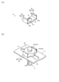
図1~図6に示す軒樋吊り具1は、上部が屋根板8の開口部8aに挿通され、開口部8aの上下方向に配された一対の第1のナット5A,5Bによって固定される吊りボルト2を備える。また、軒樋吊り具1は、孔部31に挿通された吊りボルト2に対して孔部31の上下方向に配された一対の第2のナット5C,5Dによって固定され、軒樋7を吊り下げ支持する樋支持具本体3を備える。吊りボルト2は、上下に分離して形成されたネジ部21A,21Bと、ネジ部21A,21B間に位置する回転操作部23とを有する。ネジ部21A,21Bの一方は逆ネジであり、一対の第2のナット5C,5Dのうちの少なくとも一方は、樋支持具本体3に対して回転禁止状態で配される。
以下、詳しく説明する。なお、軒樋吊り具1が屋根板8に固定されている状態を基準にして、上下方向を規定する。また、本実施形態における第1のナット5A,5B及び第2のナット5C,5Dは平面視して六角形の外周面を有する六角ナットである。
Hereinafter, an embodiment of the present invention will be described with reference to the drawings.
The eaves gutter hanger 1 shown in Figures 1 to 6 includes a hanging bolt 2 whose upper portion is inserted into an opening 8a of a roof panel 8 and fixed by a pair of first nuts 5A, 5B arranged in the vertical direction of the opening 8a. The eaves gutter hanger 1 also includes a gutter support body 3 that is fixed to the hanging bolt 2 inserted into a hole 31 by a pair of second nuts 5C, 5D arranged in the vertical direction of the hole 31, and supports the eaves gutter 7 by suspending it. The hanging bolt 2 has threaded portions 21A, 21B formed separately at the top and bottom, and a rotation operation portion 23 located between the threaded portions 21A, 21B. One of the threaded portions 21A, 21B is a reverse thread, and at least one of the pair of second nuts 5C, 5D is arranged in a rotation-prohibited state with respect to the gutter support body 3.
This will be explained in detail below. The up and down directions are defined based on the state in which the eaves gutter hanger 1 is fixed to the roof panel 8. The first nuts 5A, 5B and the second nuts 5C, 5D in this embodiment are hexagonal nuts having a hexagonal outer circumferential surface in a plan view.

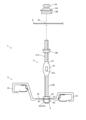
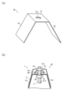
図1(a)は、屋根板8に固定されている状態の軒樋吊り具1の模式的側面図である。図1(a)等に示す吊りボルト2は、ステンレス等の金属材からなる、上下方向に延びる略丸棒状の部材である。吊りボルト2は、上下方向に分離して設けられた雄ネジであるネジ部21A,21Bを有している。本実施形態では、上側のネジ部21Aと下側のネジ部21Bとは、ネジ山のピッチが同じになるように形成された雄ネジである。吊りボルト2の上端部に設けられた上側のネジ部21Aは、屋根板8の開口部8aに挿通された状態で、第1のナット5A,5Bが屋根板8を挟持するように締結される。この締結により、吊りボルト2が屋根板8に固定される。吊りボルト2の下端部に設けられた下側のネジ部21Bは、樋支持具本体3の孔部31に挿通された状態で、第2のナット5C,5Dが樋支持具本体3の孔部31が設けられている本体部30を挟持するように締結される。この締結により、樋支持具本体3が吊りボルト2に固定される。 Figure 1 (a) is a schematic side view of the eaves gutter hanger 1 fixed to the roof shingle 8. The hanging bolt 2 shown in Figure 1 (a) is a generally round bar-shaped member extending in the vertical direction, made of a metal material such as stainless steel. The hanging bolt 2 has threaded portions 21A and 21B, which are male threads separated in the vertical direction. In this embodiment, the upper threaded portion 21A and the lower threaded portion 21B are male threads formed so that the thread pitch is the same. The upper threaded portion 21A provided at the upper end of the hanging bolt 2 is inserted into the opening 8a of the roof shingle 8, and the first nuts 5A and 5B are fastened so as to clamp the roof shingle 8. This fastening fixes the hanging bolt 2 to the roof shingle 8. The lower threaded portion 21B provided at the lower end of the hanging bolt 2 is inserted into the hole 31 of the gutter support body 3, and the second nuts 5C and 5D are fastened so as to clamp the body portion 30 in which the hole 31 of the gutter support body 3 is provided. This fastening fixes the gutter support body 3 to the hanging bolt 2.

また、下側のネジ部21Bは、上側のネジ部21Aとは異なり、逆ネジ(左ネジ)として構成されている。下側のネジ部21Bは、進行方向に対して右回し(時計回り)で螺進(進行)、左回し(反時計回り)で螺退(後退)する上側のネジ部21Aのような通常のネジとは異なり、右回しで螺退、左回しで螺進する。上側のネジ部21Aと下側のネジ部21Bとの間には、雄ネジが形成されていない部位22が設けられており、当該部位22に回転操作部23が設けられている。 Unlike the upper threaded portion 21A, the lower threaded portion 21B is configured as a reverse thread (left-handed thread). Unlike a normal screw like the upper threaded portion 21A, which advances (advances) when turned to the right (clockwise) and retracts (retreats) when turned to the left (counterclockwise) with respect to the direction of travel, the lower threaded portion 21B retracts when turned to the right and advances when turned to the left. Between the upper threaded portion 21A and the lower threaded portion 21B, a portion 22 where no male thread is formed is provided, and a rotation operation portion 23 is provided in this portion 22.

吊りボルト2は、ネジ部21A,21B間の部位22を変形させて設けられた回転操作部23を有する。本実施形態における回転操作部23は、吊りボルト2の上下方向の略中央部分の厚みがネジ部21A,21Bよりも小さくなるように扁平状に変形して形成されている(図1(a)及び図1(a)のA-A’線矢視断面図である図1(b)参照)。この回転操作部23の略中央部には、回転操作部23の厚さ方向に貫通する貫通孔23aが設けられている。この貫通孔23aは、角孔であり、後述する回転操作棒9が挿通される。 The hanging bolt 2 has a rotation operation part 23 provided by deforming the portion 22 between the threaded parts 21A and 21B. In this embodiment, the rotation operation part 23 is deformed into a flat shape so that the thickness of the approximate center part in the vertical direction of the hanging bolt 2 is smaller than that of the threaded parts 21A and 21B (see Fig. 1(a) and Fig. 1(b), which is a cross-sectional view taken along line A-A' in Fig. 1(a)). A through hole 23a is provided in the approximate center of this rotation operation part 23, penetrating it in the thickness direction. This through hole 23a is a square hole, through which the rotation operation rod 9, described later, is inserted.

吊りボルト2の下側のネジ部21Bに固定される樋支持具本体3は、ステンレス等の金属材からなる長尺状の部材であり、その長手方向(図1(a)の紙面上における左右方向)の両端部に軒樋7の前耳7a、後耳7bを保持する耳保持部32,32が形成されている。また、耳保持部32,32の間にある本体部30には、樋支持具本体3の長手方向に沿って延びる長孔状の孔部31が形成されている。 The gutter support body 3, which is fixed to the lower threaded portion 21B of the hanging bolt 2, is a long member made of a metal material such as stainless steel, and has ear holders 32, 32 formed at both ends in the longitudinal direction (left-right direction on the paper surface of FIG. 1(a)) that hold the front ears 7a and rear ears 7b of the eaves gutter 7. In addition, the body portion 30 between the ear holders 32, 32 has an elongated hole portion 31 formed in it that extends along the longitudinal direction of the gutter support body 3.

第2のナット5C,5Dは、逆ネジである下側のネジ部21Bに対して螺合可能となる雌ネジ溝が形成されている。また、第2のナット5C,5Dのうち、孔部31(樋支持具本体3)の下方に配される第2のナット5Dは、回転禁止部材4によって、樋支持具本体3に対して回転禁止状態で配されている。図2(a)に示す回転禁止部材4は、ステンレス等の金属板からなり、吊りボルト2が挿通される貫通孔41が設けられた長方形状の基板部40を有する。基板部40の短手方向の両端面の略中央部には、樋支持具本体3の孔部31の短手方向(幅方向)に沿って挿通される挿通部42,42が形成されている。挿通部42は、基板部40から略直角に折曲形成され、挿通部42の長手方向の寸法は、樋支持具本体3の孔部31の短手寸法と略同一であり、その上下寸法は、樋支持具本体3の孔部31の上下(厚さ)寸法と略同一である。 The second nuts 5C and 5D have female thread grooves that can be screwed into the lower threaded portion 21B, which is a reverse thread. The second nuts 5C and 5D, which are arranged below the hole 31 (gutter support body 3), are arranged in a rotation-prohibited state relative to the gutter support body 3 by the rotation-prohibiting member 4. The rotation-prohibiting member 4 shown in FIG. 2(a) is made of a metal plate such as stainless steel, and has a rectangular base plate 40 with a through hole 41 through which the hanging bolt 2 is inserted. The base plate 40 has insertion portions 42, 42 that are inserted along the short side (width direction) of the hole 31 of the gutter support body 3 at approximately the center of both end faces in the short side direction. The insertion portion 42 is formed by bending it at a substantially right angle from the base portion 40, and the longitudinal dimension of the insertion portion 42 is substantially the same as the short dimension of the hole portion 31 of the gutter support body 3, and its vertical dimension is substantially the same as the vertical (thickness) dimension of the hole portion 31 of the gutter support body 3.

回転禁止部材4の基板部40の長手方向の両端部40a,40aには、下側の第2のナット5Dを抱持するナット抱持部43,43が形成されている。ナット抱持部43は、基板部40の長手方向の端部40aから略直角に折曲形成されて第2のナット5Dの外周面に当接する側板部43aと、側板部43aから貫通孔41側に略直角に折曲形成されて第2のナット5Dの下面に当接する下板部43bとを備える。図2(b)に示すように、側板部43a,43a間は、第2のナット5Dの径(第2のナット5Dの外周面の対向面間)と略同程度の間隔が設けられ、基板部40及び下板部43b間は、第2のナット5Dの高さと略同程度の間隔が設けられている。 Nut holding portions 43, 43 that hold the lower second nut 5D are formed on both longitudinal ends 40a, 40a of the base plate portion 40 of the rotation prohibiting member 4. The nut holding portion 43 includes a side plate portion 43a that is bent at a substantially right angle from the longitudinal end portion 40a of the base plate portion 40 and abuts against the outer circumferential surface of the second nut 5D, and a lower plate portion 43b that is bent at a substantially right angle from the side plate portion 43a toward the through hole 41 and abuts against the lower surface of the second nut 5D. As shown in FIG. 2(b), the side plate portions 43a, 43a are spaced apart at a distance substantially equal to the diameter of the second nut 5D (between the opposing surfaces of the outer circumferential surface of the second nut 5D), and the base plate portion 40 and the lower plate portion 43b are spaced apart at a distance substantially equal to the height of the second nut 5D.

次に、上述のようにして構成された軒樋吊り具1を屋根板8に固定する方法の一例について、図3~図6を参照しながら説明する。なお、固定する方法は以下の手順や方法に限定されることはない。
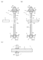
図3に示すように、吊りボルト2の上側のネジ部21Aの所望の位置に下側の第1のナット5Bを固定させる。そして、逆ネジである下側のネジ部21Bに、上から第2のナット5C、樋支持具本体3、回転禁止部材4、第2のナット5Dの順番で固定させる。このとき、回転禁止部材4の挿通部42が樋支持具本体3の孔部31の短手方向に沿うように配する。そして、ネジ部21Bに樋支持具本体3が固定された吊りボルト2の上側のネジ部21Aを屋根板8の開口部8aに挿通させる。吊りボルト2が所定の位置に達したら、吊りボルト2の上側のネジ部21Aの開口部8aの上方に露出した部分に、下からパッキン6B、山座金6A、第1のナット5Aの順番に挿通させて、吊りボルト2を屋根板8に固定する。なお、第1のナット5A、山座金6A、パッキン6Bは、一体に構成されているものでもよい。その場合、第1のナット5Aは、山座金6Aに対して回転可能な状態で構成されてもよく、山座金6Aに対して回転できない固定された状態で構成されてもよい。上述のようにして、吊りボルト2及び樋支持具本体3を備える軒樋吊り具1が、屋根板8に固定される。
Next, an example of a method for fixing the eaves gutter hanger 1 configured as described above to the roof panel 8 will be described with reference to Figures 3 to 6. Note that the fixing method is not limited to the following procedure or method.
As shown in FIG. 3, the lower first nut 5B is fixed to the desired position of the upper threaded portion 21A of the hanging bolt 2. Then, the second nut 5C, the gutter support body 3, the rotation preventing member 4, and the second nut 5D are fixed to the lower threaded portion 21B, which is a reverse thread, in this order from the top. At this time, the insertion portion 42 of the rotation preventing member 4 is arranged along the short direction of the hole portion 31 of the gutter support body 3. Then, the upper threaded portion 21A of the hanging bolt 2, to which the gutter support body 3 is fixed to the threaded portion 21B, is inserted into the opening 8a of the roof panel 8. When the hanging bolt 2 reaches a predetermined position, the gasket 6B, the mountain washer 6A, and the first nut 5A are inserted from below into the part exposed above the opening 8a of the upper threaded portion 21A of the hanging bolt 2, in that order, to fix the hanging bolt 2 to the roof panel 8. The first nut 5A, the mountain washer 6A, and the gasket 6B may be integrally formed. In this case, the first nut 5A may be configured in a state in which it can rotate with respect to the washer 6A, or may be configured in a state in which it cannot rotate with respect to the washer 6A. In the manner described above, the eaves gutter hanger 1 including the hanging bolt 2 and the gutter support body 3 is fixed to the roof panel 8.

次に、軒樋吊り具1が屋根板8に固定された後、樋支持具本体3が吊り下げ支持する軒樋7の水勾配のために、軒樋吊り具1の高さ調整を行う方法の一例について説明する。以下では、樋支持具本体3を上側に移動させる場合を説明する。まず、上側の第1のナット5Aが吊りボルト2の回転に伴う第1のナット5Aの共回りを抑制するために、不図示のクランプ等の工具によって上側の第1のナット5Aの回転が固定される。共回りとは、ナットがボルトとともに回転することをいう。 Next, an example of a method for adjusting the height of the eaves gutter hanger 1 after the eaves gutter hanger 1 is fixed to the roof panel 8 in order to adjust the water gradient of the eaves gutter 7 suspended and supported by the gutter support body 3 will be described. Below, a case in which the gutter support body 3 is moved upward will be described. First, the rotation of the upper first nut 5A is fixed by a tool such as a clamp (not shown) to prevent the first nut 5A on the upper side from rotating together with the hanging bolt 2 as it rotates. "Co-rotating" means that the nut rotates together with the bolt.

図4(a)(b)に示すように回転操作部23の貫通孔23aに挿通させた回転操作棒9を、吊りボルト2の軸方向に沿って図4(c)の二点鎖線矢印方向に回転させる。このとき、樋支持具本体3が吊りボルト2の回転に伴い回転しないように手で押さえながら吊りボルト2を回転させる。第1のナット5Aは不図示の工具によって、第2のナット5Dは回転禁止部材4によって、それぞれ吊りボルト2の回転に伴う共回りが抑制されているので、図5に示すように吊りボルト2は屋根板8に対して上方向に螺進して距離a移動する。 As shown in Figures 4(a) and (b), the rotation operating rod 9 inserted through the through hole 23a of the rotation operating part 23 is rotated in the direction of the two-dot chain arrow in Figure 4(c) along the axial direction of the hanging bolt 2. At this time, the hanging bolt 2 is rotated while holding the gutter support body 3 by hand so that it does not rotate with the rotation of the hanging bolt 2. The first nut 5A is prevented from rotating with the rotation of the hanging bolt 2 by a tool (not shown), and the second nut 5D is prevented from rotating with the rotation of the hanging bolt 2 by the rotation prohibition member 4, so that the hanging bolt 2 threads upward relative to the roof panel 8 and moves a distance a as shown in Figure 5.

また、手で回転が止められている樋支持具本体3は、吊りボルト2の回転に伴い、下側のネジ部21Bに対して上方向に距離a移動する。下側のネジ部21Bは逆ネジに構成されているので、上側のネジ部21Aが螺進して吊りボルト2が上方に移動するときは、樋支持具本体3は下側のネジ部21Bに対して上側に移動する。 The gutter support body 3, which is manually stopped from rotating, moves upward a distance a relative to the lower threaded portion 21B as the hanging bolt 2 rotates. Because the lower threaded portion 21B is configured as a reverse thread, when the upper threaded portion 21A screws forward and the hanging bolt 2 moves upward, the gutter support body 3 moves upward relative to the lower threaded portion 21B.

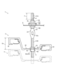
上側のネジ部21Aと下側のネジ部21Bとは、ネジ山のピッチが同じであるため、上述のようにして吊りボルト2が螺進によって屋根板8に対して距離a上側に移動するとき、樋支持具本体3は下側のネジ部21Bに対して同様に距離a上側に移動する。つまり、樋支持具本体3は、図6に示すように吊りボルト2の移動する距離aと下側のネジ部21Bに対して移動する距離aとを合わせた距離2a分だけ上側に移動する。そのため、吊りボルト2の上下方向の移動量よりも樋支持具本体3の上下方向の移動量の方が大きいので、吊りボルト2のわずかな回転量によって屋根板8と樋支持具本体3との間隔が調整でき、作業時間を短縮することが可能となる。 The upper threaded portion 21A and the lower threaded portion 21B have the same thread pitch, so when the hanging bolt 2 moves upward by a distance a relative to the roof panel 8 as described above, the gutter support body 3 also moves upward by a distance a relative to the lower threaded portion 21B. In other words, as shown in FIG. 6, the gutter support body 3 moves upward by a distance 2a, which is the sum of the distance a moved by the hanging bolt 2 and the distance a moved relative to the lower threaded portion 21B. Therefore, since the vertical movement of the gutter support body 3 is greater than the vertical movement of the hanging bolt 2, the distance between the roof panel 8 and the gutter support body 3 can be adjusted by a slight rotation of the hanging bolt 2, making it possible to shorten the work time.

なお、本実施形態では、回転操作部23の貫通孔23aに回転操作棒9を挿通させて吊りボルト2を回転させているが、回転操作棒9を用いずに、回転操作部23を手でつかんで吊りボルト2を回転させてもよい。また、本実施形態では、下側の第1のナット5B及び上側の第2のナット5Cは回転禁止状態で配されていないので、吊りボルト2の回転に伴い共回りする。そのため、吊りボルト2の上側への移動に伴い、下側の第1のナット5Bは屋根板8に接触する。また、上方向に移動する吊りボルト2は、ネジ部21Bの下方向への螺進に伴い、樋支持具本体3に対して下側へ相対移動するため、上側の第2のナット5Cは樋支持具本体3に接触する。そして、その接触に伴う摩擦力によって、下側の第1のナット5B及び上側の第2のナット5Cは固定されて共回りが抑制され、回転禁止状態となる。 In this embodiment, the hanging bolt 2 is rotated by inserting the rotating rod 9 through the through hole 23a of the rotating operation part 23, but the hanging bolt 2 may be rotated by grasping the rotating operation part 23 by hand without using the rotating rod 9. In addition, in this embodiment, the lower first nut 5B and the upper second nut 5C are not arranged in a rotation-prohibited state, so they rotate together with the hanging bolt 2 as it rotates. Therefore, as the hanging bolt 2 moves upward, the lower first nut 5B comes into contact with the roof panel 8. In addition, the hanging bolt 2 moving upward moves downward relative to the gutter support body 3 as the threaded portion 21B is screwed downward, so the upper second nut 5C comes into contact with the gutter support body 3. Then, due to the frictional force associated with this contact, the lower first nut 5B and the upper second nut 5C are fixed and the rotation together is suppressed, resulting in a rotation-prohibited state.

なお、材質等の関係で、屋根板8、樋支持具本体3との間に第1のナット5B及び第2のナット5Cの共回りを抑制するほどの摩擦力が発生せず、第1のナット5B及び第2のナット5Cによって吊りボルト2を上方向に移動させることが困難になる場合がある。その場合は、一度第1のナット5B及び第2のナット5Cを回転させて緩めた後に吊りボルト2を再び回転させればよい。また、第1のナット5Bと屋根板8との間、第2のナット5Cと樋支持具本体3との間に、摩擦力を増大させるワッシャや、付勢力によって押圧して第1のナット5Bや第2のナット5Cの共回りを止める板バネ等の金具等が介在する構成であってもよい。 Note that, due to the nature of the materials, etc., there may be cases where the frictional force between the roof panel 8 and the gutter support body 3 is not sufficient to prevent the first nut 5B and the second nut 5C from rotating together, making it difficult to move the hanging bolt 2 upwards using the first nut 5B and the second nut 5C. In that case, the first nut 5B and the second nut 5C can be rotated once to loosen them, and then the hanging bolt 2 can be rotated again. In addition, a washer that increases the frictional force, or a metal fitting such as a leaf spring that applies a biasing force to press and stop the first nut 5B and the second nut 5C from rotating together may be interposed between the first nut 5B and the roof panel 8, and between the second nut 5C and the gutter support body 3.

また、高さ調整を行う前にあらかじめ下側の第1のナット5B及び上側の第2のナット5Cが、それぞれ屋根板8及び樋支持具本体3に対して所定の間隔を設けた状態にしてから高さ調整を行ってもよい。また、下側の第1のナット5B及び上側の第2のナット5Cは、第1のナット5A及び第2のナット5Dと同様に、高さ調整を行う前に不図示の工具等によってそれぞれ回転禁止状態で配されてもよい。そのようにすれば、吊りボルト2の回転に伴い下側の第1のナット5B及び上側の第2のナット5Cが共回りしないので、スムーズに樋支持具本体3の高さ調整を行うことができる。 Also, before adjusting the height, the lower first nut 5B and the upper second nut 5C may be set to a predetermined distance from the roof panel 8 and the gutter support body 3, respectively, before adjusting the height. Also, the lower first nut 5B and the upper second nut 5C may be arranged in a rotation-prohibited state using a tool (not shown) before adjusting the height, similar to the first nut 5A and the second nut 5D. In this way, the lower first nut 5B and the upper second nut 5C do not rotate together with the rotation of the hanging bolt 2, so the height adjustment of the gutter support body 3 can be performed smoothly.

また、上述の説明では、樋支持具本体3を上方向に移動させる場合の高さ調整の例について説明しているが、樋支持具本体3を下方向に移動させて高さ調整を行ってもよい。その場合は、吊りボルト2を上方向に移動させる時とは逆回りに回転させることによって、吊りボルト2が下方向に移動し、さらに樋支持具本体3は下側のネジ部21Bに対して下方向に移動する。なお、本実施形態では、下側の第1のナット5B及び上側の第2のナット5Cは回転禁止状態で配されていないので、吊りボルト2の回転に伴い共回りすることによって、それぞれ屋根板8及び樋支持具本体3に離隔してしまう。その場合は、樋支持具本体3の高さ調整が行われた後、あらためて下側の第1のナット5B及び上側の第2のナット5Cを締結させて屋根板8に吊りボルト2を、吊りボルト2に樋支持具本体3を固定させればよい。上側の第1のナット5A及び下側の第2のナット5Dが固定されているので、吊りボルト2や樋支持具本体3から手を離しても落下するおそれがない。そのため、樋支持具本体3の高さ調整を行った後に、余裕をもって下側の第1のナット5B及び上側の第2のナット5Cの締結作業を行うことができる。 In the above description, an example of height adjustment when the gutter support body 3 is moved upward is described, but the height adjustment may be performed by moving the gutter support body 3 downward. In that case, the hanging bolt 2 is rotated in the opposite direction to the direction in which it is moved upward, so that the hanging bolt 2 moves downward, and the gutter support body 3 moves downward relative to the lower screw portion 21B. In this embodiment, the lower first nut 5B and the upper second nut 5C are not arranged in a rotation-prohibited state, so that they rotate together with the hanging bolt 2 as it rotates, and are separated from the roof plate 8 and the gutter support body 3, respectively. In that case, after the height adjustment of the gutter support body 3 is performed, the lower first nut 5B and the upper second nut 5C are tightened again to fix the hanging bolt 2 to the roof plate 8 and the gutter support body 3 to the hanging bolt 2. Because the upper first nut 5A and the lower second nut 5D are fixed, there is no risk of them falling even if you let go of the hanging bolt 2 or the gutter support body 3. Therefore, after adjusting the height of the gutter support body 3, you can easily tighten the lower first nut 5B and the upper second nut 5C.

なお、下側の第1のナット5B及び上側の第2のナット5Cは、高さ調整を行う前に回転禁止状態で配されていれば、吊りボルト2の回転に伴い共回りしないので、屋根板8及び樋支持具本体3から離隔しない。そのため、下側の第1のナット5B及び上側の第2のナット5Cが回転禁止状態で配されていれば、高さ調整を行った後に締結作業を行う必要がなくなり、スムーズに樋支持具本体3の高さ調整を行うことができる。つまり、上側の第1のナット5A及び下側の第2のナット5Dと同様に、下側の第1のナット5B及び上側の第2のナット5Cが回転禁止状態で配されていれば、樋支持具本体3の上方向、下方向の両方の高さ調整をスムーズに行うことができる。 If the lower first nut 5B and the upper second nut 5C are arranged in a rotation-prohibited state before the height adjustment, they will not rotate together with the rotation of the hanging bolt 2, and will not separate from the roof panel 8 and the gutter support body 3. Therefore, if the lower first nut 5B and the upper second nut 5C are arranged in a rotation-prohibited state, there is no need to perform fastening work after the height adjustment, and the height adjustment of the gutter support body 3 can be performed smoothly. In other words, if the lower first nut 5B and the upper second nut 5C are arranged in a rotation-prohibited state, like the upper first nut 5A and the lower second nut 5D, the height adjustment of the gutter support body 3 in both the upward and downward directions can be performed smoothly.

上述の軒樋吊り具1の高さ調整では、不図示の共回り防止用の工具によって、屋根板8の開口部8aの上方に配された第1のナット5Aが屋根板8に対して回転禁止状態で配されているが、これに限定されることはない。例えば、屋根板8の開口部8aが角孔として形成されていれば、図7(a)(b)に示すように、山座金6Aが開口部8aの縁部に沿って挿通される板状の挿通部6Aaを有する回転禁止部材として構成されてもよい。山座金6Aは、一対の挿通部6Aa,6Aaが互いの面部が対向するように配されている。上側の第1のナット5Aは、回転が固定された状態で、回転禁止部材である山座金6Aと一体に構成されている。そのため、山座金6Aの挿通部6Aa,6Aaが開口部8aの縁部に沿って挿通されることで、上側の第1のナット5Aが屋根板8に対して回転禁止状態で配される。 In the height adjustment of the eaves gutter hanger 1 described above, the first nut 5A arranged above the opening 8a of the roof plate 8 is arranged in a rotation-prohibited state relative to the roof plate 8 by a co-rotation prevention tool (not shown), but this is not limited to this. For example, if the opening 8a of the roof plate 8 is formed as a square hole, as shown in Figures 7 (a) and (b), the mountain washer 6A may be configured as a rotation-prohibiting member having a plate-shaped insertion portion 6Aa that is inserted along the edge of the opening 8a. The mountain washer 6A is arranged so that the pair of insertion portions 6Aa, 6Aa face each other. The upper first nut 5A is configured integrally with the mountain washer 6A, which is a rotation-prohibiting member, in a state in which rotation is fixed. Therefore, the insertion portions 6Aa, 6Aa of the mountain washer 6A are inserted along the edge of the opening 8a, and the upper first nut 5A is arranged in a rotation-prohibited state relative to the roof plate 8.

また、回転禁止部材として機能する山座金6Aの変形例としては、図7(c)(d)に示すようなものが挙げられる。図7(c)(d)では、山座金6Aが、図7(a)(b)の挿通部6Aaに加え、上側の第1のナット5Aの外周面及び下面の少なくともそれぞれの一部に当接して上側の第1のナット5Aを抱持するナット抱持部6Abを有する。上側の第1のナット5Aは、図7(a)(b)と異なり山座金6Aと一体に構成されていない。上側の第1のナット5Aは、山座金6Aのナット抱持部6Abに抱持された状態で、山座金6Aの挿通部6Aa,6Aaが屋根板8の開口部8aの縁部に沿った状態で挿通されることで、屋根板8に対して回転禁止状態で配される。 Modifications of the mountain washer 6A that function as a rotation-preventing member include those shown in Figs. 7(c) and (d). In Figs. 7(c) and (d), the mountain washer 6A has, in addition to the insertion portion 6Aa of Figs. 7(a) and (b), a nut holding portion 6Ab that holds the upper first nut 5A by abutting at least a portion of the outer circumferential surface and the lower surface of the upper first nut 5A. Unlike Figs. 7(a) and (b), the upper first nut 5A is not integrally formed with the mountain washer 6A. The upper first nut 5A is held by the nut holding portion 6Ab of the mountain washer 6A, and the insertion portions 6Aa, 6Aa of the mountain washer 6A are inserted along the edge of the opening 8a of the roof panel 8, so that the upper first nut 5A is arranged in a rotation-preventing state relative to the roof panel 8.

また、屋根板8が折板屋根の場合、図8(a)に示すようなカバー部材80を用いて上側の第1のナット5Aが屋根板8に対して回転禁止状態で配されてもよい。カバー部材80は、丸孔状の開口部8a付近の屋根板8の形状に沿って折曲されたステンレス等の金属板によって形成されている。カバー部材80は、上板部81と、上板部81の両端部に設けられ、屋根板8の一部を幅方向(建物に対する見付の方向と一致する方向、図8(b)の紙面上における左右方向)から挟み込む側板部82,82とを有する。上板部81には、第1のナット5Aの外周面に沿う形状に形成された貫通孔81aが設けられている。図8(b)に示すように、第1のナット5A、山座金6A、パッキン6Bが上方に配された状態の屋根板8の上方から覆うようにカバー部材80が配される。これにより、第1のナット5Aがカバー部材80の貫通孔81aにはまり、上側の第1のナット5Aが屋根板8に対して回転禁止状態で配される。 In addition, when the roof plate 8 is a folded plate roof, the upper first nut 5A may be arranged in a rotation-prohibited state relative to the roof plate 8 using a cover member 80 as shown in FIG. 8(a). The cover member 80 is formed of a metal plate such as stainless steel bent along the shape of the roof plate 8 near the round hole-shaped opening 8a. The cover member 80 has an upper plate portion 81 and side plate portions 82, 82 provided at both ends of the upper plate portion 81 and sandwiching a part of the roof plate 8 from the width direction (the direction that coincides with the direction of appearance relative to the building, the left-right direction on the paper surface of FIG. 8(b)). The upper plate portion 81 is provided with a through hole 81a formed in a shape that follows the outer peripheral surface of the first nut 5A. As shown in FIG. 8(b), the cover member 80 is arranged so as to cover from above the roof plate 8 in a state in which the first nut 5A, the mountain washer 6A, and the packing 6B are arranged above. This causes the first nut 5A to fit into the through hole 81a of the cover member 80, and the upper first nut 5A is positioned in a non-rotatable state relative to the roof panel 8.

また、カバー部材80の構成は図示したものに限定されることはない。例えば、貫通孔81aが吊りボルト2が挿通される丸孔形状に形成され、この貫通孔81aの上側または下側に、上側の第1のナット5Aが溶接等で固着されることで、カバー部材80と上側の第1のナット5Aとが一体に構成されてもよい。 The configuration of the cover member 80 is not limited to that shown in the figure. For example, the through hole 81a may be formed in a round hole shape through which the hanging bolt 2 is inserted, and the upper first nut 5A may be fixed to the upper or lower side of this through hole 81a by welding or the like, so that the cover member 80 and the upper first nut 5A are integrally configured.

次に図9(a)~(f)を参照しながら吊りボルト2の回転操作部23の変形例について説明する。なお、図9(a)(c)(e)は、それぞれ変形例に係る吊りボルトの模式的側面図であり、図9(b)は、図9(a)のD-D’線矢視拡大断面図、図9(d)は、図9(c)のE-E’線矢視拡大断面図、図9(f)は、図9(e)のF-F’線矢視拡大断面図である。 Next, modified examples of the rotation operation part 23 of the hanging bolt 2 will be described with reference to Figs. 9(a) to (f). Figs. 9(a), (c), and (e) are schematic side views of the hanging bolt according to the modified examples, Fig. 9(b) is an enlarged cross-sectional view taken along line D-D' in Fig. 9(a), Fig. 9(d) is an enlarged cross-sectional view taken along line E-E' in Fig. 9(c), and Fig. 9(f) is an enlarged cross-sectional view taken along line F-F' in Fig. 9(e).

図9(a)(b)に示す回転操作部23は、ネジ部21A,21B間の部位22の一部を変形させて設けられており、その横断面形状は、ネジ部21A,21Bの横断面面積よりも小さい略正方形状の矩形状に形成されている。回転操作部23の横断面形状が矩形状に形成されているので、回転操作部23を手でつかんで回しやすくなっている。 The rotation operation part 23 shown in Figures 9(a) and (b) is provided by deforming a part of the area 22 between the threaded parts 21A and 21B, and its cross-sectional shape is formed into a substantially square rectangular shape that is smaller than the cross-sectional area of the threaded parts 21A and 21B. Because the cross-sectional shape of the rotation operation part 23 is formed into a rectangle, it is easy to grasp and turn the rotation operation part 23 by hand.

図9(c)(d)及び図9(e)(f)に示す回転操作部23は、ネジ部21A,21B間の部位22に固定させた別体の把持部材24によって構成されている。図9(c)(d)では、矩形状の板材である把持部材24の中心部が吊りボルト2に沿うように変形させた状態で溶接等によって吊りボルト2に固定されることによって、回転操作部23が構成されている。 The rotation operation unit 23 shown in Figs. 9(c)(d) and 9(e)(f) is composed of a separate gripping member 24 fixed to the portion 22 between the screw portions 21A and 21B. In Figs. 9(c)(d), the center of the gripping member 24, which is a rectangular plate material, is deformed to fit the hanging bolt 2 and then fixed to the hanging bolt 2 by welding or the like, thereby forming the rotation operation unit 23.

図9(e)(f)では、吊りボルト2の下側のネジ部21Bの上端部まで挿通された六角ナットである把持部材24が、溶接等によって吊りボルト2に固定されることによって回転操作部23が、上側のネジ部21Aと下側のネジ部21Bとの間に構成されている。 In Figures 9(e) and (f), a gripping member 24, which is a hexagonal nut inserted up to the upper end of the lower threaded portion 21B of the hanging bolt 2, is fixed to the hanging bolt 2 by welding or the like, so that a rotation operation portion 23 is formed between the upper threaded portion 21A and the lower threaded portion 21B.

軒樋吊り具1の構成は、上述したものや図示したものに限定されることはない。例えば、吊りボルト2は、下側のネジ部21Bではなく上側のネジ部21Aが逆ネジとして構成されてもよく、また、上側のネジ部21Aと下側のネジ部21Bは、その長さが異なって構成されていてもよい。特に下側のネジ部21Bが上側のネジ部21Aよりも長く構成されていれば、樋支持具本体3の高さ調整の範囲を大きくすることができる。さらに、上側のネジ部21Aと下側のネジ部21Bとで、ネジ山のピッチを異ならせたものでもよい。 The configuration of the eaves gutter hanger 1 is not limited to that described above or shown in the figures. For example, the hanging bolt 2 may be configured with a reverse thread on the upper thread portion 21A instead of the lower thread portion 21B, and the upper thread portion 21A and the lower thread portion 21B may be configured with different lengths. In particular, if the lower thread portion 21B is configured to be longer than the upper thread portion 21A, the range of height adjustment of the gutter support body 3 can be increased. Furthermore, the upper thread portion 21A and the lower thread portion 21B may have different thread pitches.

また、例えば、図1~図6に示す回転操作部23に貫通孔23aが設けられていなくてもよく、図9(c)(d)の回転操作部23に、回転操作棒9が挿通されるための貫通孔が設けられてもよい。その他の部材の構成も、適宜設計されればよい。また、上側の第1のナット5Aは、開口部8aに連通するように屋根板8に溶接等で直接固着されて、屋根板8に対して回転禁止状態で配されてもよい。また、下側の第2のナット5Dは、回転禁止状態で配するために、回転禁止部材4を用いることに限定されることはない。下側の第2のナット5Dは、上側の第1のナット5Aと同様に工具等を用いて回転禁止状態で配されてもよく、樋支持具本体3の下面に孔部31に連通するように溶接等で固着されることで、樋支持具本体3に対して回転禁止状態で配されてもよい。下側の第1のナット5B及び上側の第2のナット5Cも同様に、種々の方法で回転禁止状態に配されてもよい。また、回転禁止部材4の構成も上述のものに限定されることはなく、材質も金属に限定されることはなく例えば合成樹脂等であってもよい。 For example, the through hole 23a may not be provided in the rotation operation part 23 shown in Figs. 1 to 6, and the rotation operation part 23 in Figs. 9(c) and (d) may be provided with a through hole for inserting the rotation operation rod 9. The configuration of other members may also be designed appropriately. The upper first nut 5A may be directly fixed to the roof plate 8 by welding or the like so as to communicate with the opening 8a, and may be arranged in a state where rotation is prohibited relative to the roof plate 8. The lower second nut 5D is not limited to using a rotation prohibiting member 4 in order to be arranged in a state where rotation is prohibited. The lower second nut 5D may be arranged in a state where rotation is prohibited using a tool or the like, similar to the upper first nut 5A, or may be arranged in a state where rotation is prohibited relative to the gutter support body 3 by being fixed by welding or the like to the lower surface of the gutter support body 3 so as to communicate with the hole 31. The lower first nut 5B and the upper second nut 5C may also be arranged in a state where rotation is prohibited by various methods. Furthermore, the configuration of the rotation prevention member 4 is not limited to that described above, and the material is not limited to metal but may be, for example, synthetic resin, etc.

また、上述の説明では、上側の第1のナット5A及び下側の第2のナット5Dが回転禁止状態に配されている場合や、一対の第1のナット5A,5B及び一対の第2のナット5C,5Dの両方が回転禁止状態で配されている場合について説明しているが、それらに限定されることはない。それらに代わり下側の第1のナット5B及び上側の第2のナット5Cのみが高さ調整を行う前に回転禁止状態に配されてもよい。下側の第1のナット5B及び上側の第2のナット5Cが回転禁止状態で配されている場合は、吊りボルト2を屋根板8に対して下方への高さ調整が行いやすくなる。また、下側の第1のナット5B及び上側の第2のナット5Cが回転禁止状態において、上側への高さ調整を行うと第2のナット5C,5D間の間隔が、下側への高さ調整を行うと第1のナット5A,5B間の間隔が、それぞれ大きくなってしまう。そのため、高さ調整の後にあらためて上側の第1のナット5Aや下側の第2のナット5Dを締結させる。これらによって、第1のナット5A,5B及び第2のナット5C,5Dが屋根板8及び樋支持具本体3を挟持して締結される。 In the above description, the first nut 5A on the upper side and the second nut 5D on the lower side are arranged in a rotation-prohibited state, or both the pair of first nuts 5A, 5B and the pair of second nuts 5C, 5D are arranged in a rotation-prohibited state, but the present invention is not limited to these. Instead, only the first nut 5B on the lower side and the second nut 5C on the upper side may be arranged in a rotation-prohibited state before the height adjustment is performed. If the first nut 5B on the lower side and the second nut 5C on the upper side are arranged in a rotation-prohibited state, it becomes easier to adjust the height of the hanging bolt 2 downward relative to the roof panel 8. In addition, when the first nut 5B on the lower side and the second nut 5C on the upper side are in a rotation-prohibited state, the distance between the second nuts 5C, 5D increases when the height adjustment is performed upward, and the distance between the first nuts 5A, 5B increases when the height adjustment is performed downward. Therefore, the first nut 5A on the upper side and the second nut 5D on the lower side are tightened again after the height adjustment. As a result, the first nuts 5A, 5B and the second nuts 5C, 5D clamp and fasten the roof panel 8 and the gutter support body 3.

また、吊りボルト2の回転操作部23の回転操作は、樋支持具本体3の高さ調整だけではなく、吊りボルト2を屋根板8に取り付ける際に行われてもよい。その場合は、吊りボルト2の取り付け作業の前に、上側の第1のナット5Aを開口部8aに連通させてから屋根板8に対して回転禁止状態で配する。そして、上側のネジ部21Aの所望の位置に下側の第1のナット5Bを螺合させて、吊りボルト2の上端部を開口部8aに通して第1のナット5Aの雌ネジ孔の端部に接触させる。その状態で吊りボルト2を回転操作部23によって回転させることで、上側のネジ部21Aは第1のナット5Aに螺合し、吊りボルト2が上側に螺進して移動する。このとき、樋支持具本体3は、手で回転が止められている状態が好ましい。そして、吊りボルト2が所望の位置に達したときに下側の第1のナット5Bが屋根板8に接触していない場合は、第1のナット5Bを締結させる。上述のようにすることで、第1のナット5A,5Bが屋根板8を挟持するように締結され、吊りボルト2が屋根板8に固定される。 The rotation operation of the rotation operation part 23 of the hanging bolt 2 may be performed not only when adjusting the height of the gutter support body 3, but also when attaching the hanging bolt 2 to the roof plate 8. In that case, before the installation work of the hanging bolt 2, the upper first nut 5A is communicated with the opening 8a and then placed in a rotation-prohibited state relative to the roof plate 8. Then, the lower first nut 5B is screwed into the desired position of the upper threaded part 21A, and the upper end of the hanging bolt 2 is passed through the opening 8a and brought into contact with the end of the female threaded hole of the first nut 5A. In this state, by rotating the hanging bolt 2 by the rotation operation part 23, the upper threaded part 21A is screwed into the first nut 5A, and the hanging bolt 2 is screwed and moved upward. At this time, it is preferable that the rotation of the gutter support body 3 is stopped by hand. Then, if the lower first nut 5B is not in contact with the roof plate 8 when the hanging bolt 2 reaches the desired position, the first nut 5B is tightened. By doing as described above, the first nuts 5A and 5B are tightened to clamp the roof panel 8, and the hanging bolt 2 is fixed to the roof panel 8.

なお、吊りボルト2の取り付け作業の前に開口部8aに連通させてから屋根板8に回転禁止状態で配されるのは上側の第1のナット5Aではなく、下側の第1のナット5Bでもよい。その場合は、下側の第1のナット5Bに螺合させた吊りボルト2が所望の位置に達してから、上側のネジ部21Aに上側の第1のナット5Aを螺合させることで、第1のナット5A,5Bが屋根板8を挟持するように締結され、吊りボルト2が屋根板8に固定される。また、上側の第1のナット5Aを締結させる前に軒樋吊り具1から手を離した状態になったときに、軒樋吊り具1の重さで下側の第1のナット5Bが屋根板8から脱落しないように、下側の第1のナット5Bは屋根板8に対して強固に固定されるのが好ましい。また、第1のナット5A,5Bの両方が、吊りボルト2の取り付け作業の前に、開口部8aに連通されて屋根板8に回転禁止状態で配されてから、吊りボルト2の屋根板8への取り付け作業を行ってもよい。 Before the installation of the hanging bolt 2, it is not the upper first nut 5A but the lower first nut 5B that is connected to the opening 8a and then placed in a rotation-prohibited state on the roof panel 8. In that case, after the hanging bolt 2 screwed into the lower first nut 5B reaches the desired position, the upper first nut 5A is screwed into the upper threaded portion 21A, so that the first nuts 5A and 5B are fastened to clamp the roof panel 8, and the hanging bolt 2 is fixed to the roof panel 8. In addition, it is preferable that the lower first nut 5B is firmly fixed to the roof panel 8 so that the weight of the eaves gutter hanger 1 does not cause the lower first nut 5B to fall off the roof panel 8 when the hand is released from the eaves gutter hanger 1 before the upper first nut 5A is fastened. Also, both of the first nuts 5A and 5B may be connected to the opening 8a and placed on the roof panel 8 in a rotation-prohibited state before the work of attaching the hanging bolt 2 to the roof panel 8.

また、本実施形態の軒樋吊り具1は、第1のナット5A,5B間や第2のナット5C,5D間が離隔した状態であっても、吊りボルト2を回転操作させることで、それらの間隔を縮める調整を行うことができる。吊りボルト2に螺合した第1のナット5A,5B間や第2のナット5C,5D間が離隔した状態で、第1のナット5A及び第2のナット5Dがそれぞれ屋根板8及び樋支持具本体3に対して回転禁止状態で配されていれば、吊りボルト2を回転操作によって上方向に移動させればよい。吊りボルト2の回転差操作だけで、第1のナット5A,5B間や第2のナット5C,5D間の間隔が縮まり、屋根板8及び樋支持具本体3が第1のナット5A,5B及び第2のナット5C,5Dによって挟み込まれるので、効率的に施工作業を行うことができる。 In addition, in the eaves gutter hanger 1 of this embodiment, even if the first nuts 5A, 5B and the second nuts 5C, 5D are spaced apart, the hanging bolt 2 can be rotated to adjust the distance between them. If the first nuts 5A, 5B and the second nuts 5C, 5D screwed onto the hanging bolt 2 are spaced apart, and the first nuts 5A and the second nuts 5D are arranged in a state where they cannot rotate relative to the roof plate 8 and the gutter support body 3, respectively, the hanging bolt 2 can be moved upward by rotating it. By simply rotating the hanging bolt 2, the distance between the first nuts 5A, 5B and the second nuts 5C, 5D is reduced, and the roof plate 8 and the gutter support body 3 are sandwiched between the first nuts 5A, 5B and the second nuts 5C, 5D, so that the construction work can be carried out efficiently.

また、軒樋7は、複数の軒樋吊り具1によって吊り下げ支持される。軒樋7が複数の軒樋吊り具1に吊り下げ支持されている状態で、軒樋7の水勾配や高さ位置の調整のために、樋支持具本体3の高さ調整、すなわち軒樋7の高さ調整を行ってもよい。軒樋7の高さを調整する場合には、複数の吊りボルト2を一斉に回転させればよく、軒樋7の水勾配の調整の場合には、該当する樋支持具本体3が固定されている吊りボルト2を回転させればよい。本実施形態の軒樋吊り具1は、吊りボルト2の回転によって樋支持具本体3の高さ調整を行うことができるので、軒樋7を吊り下げ支持している状態でも高さ調整を行うことができる。 The eaves gutter 7 is suspended and supported by multiple eaves gutter hangers 1. When the eaves gutter 7 is suspended and supported by multiple eaves gutter hangers 1, the height of the gutter support body 3, i.e., the height of the eaves gutter 7, may be adjusted to adjust the water gradient and height position of the eaves gutter 7. To adjust the height of the eaves gutter 7, multiple hanging bolts 2 may be rotated simultaneously, and to adjust the water gradient of the eaves gutter 7, the hanging bolt 2 to which the corresponding gutter support body 3 is fixed may be rotated. The eaves gutter hanger 1 of this embodiment can adjust the height of the gutter support body 3 by rotating the hanging bolt 2, so that the height can be adjusted even when the eaves gutter 7 is suspended and supported.

1 軒樋吊り具
2 吊りボルト
21A,21B ネジ部
23 回転操作部
24 把持部材
3 樋支持具本体
31 孔部
4 回転禁止部材
5A,5B 第1のナット
5C,5D 第2のナット
6A 山座金(回転禁止部材)
7 軒樋
8 屋根板
8a 開口部
9 回転操作棒

REFERENCE SIGNS LIST 1 Eaves gutter hanging tool 2 Hanging bolt 21A, 21B Threaded part 23 Rotation operation part 24 Grip member 3 Gutter support tool main body 31 Hole part 4 Rotation prevention member 5A, 5B First nut 5C, 5D Second nut 6A Hex washer (rotation prevention member)
7 Eaves gutter 8 Roof plate 8a Opening 9 Rotation control rod

Claims (8)

上部が屋根板の開口部に挿通され、前記開口部の上下方向に配された一対の第1のナットによって固定される吊りボルトと、孔部に挿通された前記吊りボルトに対して前記孔部の上下方向に配された一対の第2のナットによって固定され、軒樋を吊り下げ支持する樋支持具本体とを備えた軒樋吊り具において、
前記吊りボルトは、上下に分離して形成されたネジ部と、該ネジ部間に位置する回転操作部とを有し、
前記ネジ部の一方は逆ネジであり、
前記一対の第2のナットの少なくとも一方は、前記樋支持具本体に対して回転禁止状態で配されることを特徴とする軒樋吊り具。
A gutter hanger includes a hanging bolt, the upper part of which is inserted into an opening in a roof panel and fixed by a pair of first nuts arranged in the vertical direction of the opening, and a gutter support body which is fixed to the hanging bolt inserted into a hole by a pair of second nuts arranged in the vertical direction of the hole and which supports and suspends an eaves gutter,
The suspension bolt has a threaded portion formed separately above and below, and a rotation operation portion located between the threaded portions,
One of the threaded portions is a reverse thread,
An eaves gutter hanger characterized in that at least one of the pair of second nuts is arranged in a non-rotating state relative to the gutter support body.
請求項1において、
前記一対の第1のナットの少なくとも一方は、前記屋根板に対して回転禁止状態で配されることを特徴とする軒樋吊り具。
In claim 1,
A gutter hanger device characterized in that at least one of the pair of first nuts is arranged in a non-rotating state relative to the roof panel.
請求項1または請求項2において、
前記回転操作部には、前記吊りボルトを回転操作させるための回転操作棒が挿通される貫通孔が設けられていることを特徴とする軒樋吊り具。
In claim 1 or 2,
The eaves gutter hanger is characterized in that the rotation operating portion is provided with a through hole through which a rotation operating rod for rotating the hanging bolt is inserted.
請求項1乃至請求項3のいずれか一項において、
前記回転操作部は、前記ネジ部間を変形させて設けられていることを特徴とする軒樋吊り具。
In any one of claims 1 to 3,
The eaves gutter hanging device is characterized in that the rotation operating portion is provided by deforming the space between the threaded portions.
請求項1乃至請求項3のいずれか一項において、
前記回転操作部は、前記ネジ部間に別体の把持部材が固定されて設けられていることを特徴とする軒樋吊り具。
In any one of claims 1 to 3,
The rotation operating portion is characterized in that a separate gripping member is fixed between the screw portions.
請求項1乃至請求項5のいずれか一項において、
前記孔部は長孔であり、
前記一対の第2のナットの少なくとも一方は、前記孔部の短手方向に沿って挿通される挿通部と、該挿通部と一体に構成され、前記第2のナットの外周面に当接して前記第2のナットを抱持するナット抱持部とを有する回転禁止部材によって、前記樋支持具本体に対して回転禁止状態で配されていることを特徴とする軒樋吊り具。
In any one of claims 1 to 5,
The hole is a long hole,
This eaves gutter hanger is characterized in that at least one of the pair of second nuts is arranged in a non-rotating state relative to the gutter support body by a rotation-preventing member having an insertion portion that is inserted along the short direction of the hole portion and a nut holding portion that is formed integrally with the insertion portion and abuts against the outer peripheral surface of the second nut to hold the second nut.
請求項2乃至請求項6のいずれか一項において、
前記開口部は角孔であり、
前記一対の第1のナットの少なくとも一方は、前記開口部の縁部の少なくとも一部に沿って挿通される挿通部を有する回転禁止部材と一体に構成されていることを特徴とする軒樋吊り具。
In any one of claims 2 to 6,
The opening is a rectangular hole,
An eaves gutter hanging device characterized in that at least one of the pair of first nuts is integrally formed with a rotation-preventing member having an insertion portion that is inserted along at least a portion of the edge of the opening.
請求項2乃至請求項6のいずれか一項において、
前記開口部は角孔であり、
前記一対の第1のナットの少なくとも一方は、前記開口部の縁部の少なくとも一部に沿って挿通される挿通部と、該挿通部と一体に構成され、前記第1のナットの外周面に当接して前記第1のナットを抱持するナット抱持部とを有する回転禁止部材によって、前記屋根板に対して回転禁止状態で配されていることを特徴とする軒樋吊り具。

In any one of claims 2 to 6,
The opening is a rectangular hole,
This eaves gutter hanger is characterized in that at least one of the pair of first nuts is arranged in a rotation-preventing state relative to the roof panel by a rotation-preventing member having an insertion portion that is inserted along at least a portion of the edge of the opening, and a nut holding portion that is formed integrally with the insertion portion and abuts against the outer peripheral surface of the first nut to hold the first nut.

JP2021144235A 2021-09-03 2021-09-03 Eaves gutter hanging equipment Active JP7560880B2 (en)

Priority Applications (1)

Application Number Priority Date Filing Date Title
JP2021144235A JP7560880B2 (en) 2021-09-03 2021-09-03 Eaves gutter hanging equipment

Applications Claiming Priority (1)

Application Number Priority Date Filing Date Title
JP2021144235A JP7560880B2 (en) 2021-09-03 2021-09-03 Eaves gutter hanging equipment

Publications (2)

Publication Number Publication Date
JP2023037462A JP2023037462A (en) 2023-03-15
JP7560880B2 true JP7560880B2 (en) 2024-10-03

Family

ID=85509151

Family Applications (1)

Application Number Title Priority Date Filing Date
JP2021144235A Active JP7560880B2 (en) 2021-09-03 2021-09-03 Eaves gutter hanging equipment

Country Status (1)

Country Link
JP (1) JP7560880B2 (en)

Citations (2)

* Cited by examiner, † Cited by third party
Publication number Priority date Publication date Assignee Title
JP2000265626A (en) 1999-03-16 2000-09-26 Sekisui Chem Co Ltd Eave gutter hanging tool
JP2015010319A (en) 2013-06-26 2015-01-19 株式会社オーティス Eaves gutter hanger

Family Cites Families (5)

* Cited by examiner, † Cited by third party
Publication number Priority date Publication date Assignee Title
JPS54122124U (en) * 1978-02-15 1979-08-27
JPS6090331U (en) * 1983-11-28 1985-06-20 株式会社長谷川工務店 Support jig for temporary water pipes
US4705242A (en) * 1987-04-22 1987-11-10 Yost George P Universal gutter mounting system
JPH0615100Y2 (en) * 1988-05-12 1994-04-20 三晃金属工業株式会社 Mounting bracket
JP2503224Y2 (en) * 1990-04-09 1996-06-26 新日軽株式会社 Simple garage

Patent Citations (2)

* Cited by examiner, † Cited by third party
Publication number Priority date Publication date Assignee Title
JP2000265626A (en) 1999-03-16 2000-09-26 Sekisui Chem Co Ltd Eave gutter hanging tool
JP2015010319A (en) 2013-06-26 2015-01-19 株式会社オーティス Eaves gutter hanger

Also Published As

Publication number Publication date
JP2023037462A (en) 2023-03-15

Similar Documents

Publication Publication Date Title
CA2722191C (en) Strut clamp
US7604444B2 (en) Fastener assembly
CA2717883A1 (en) Friction lock bolt
US20020066834A1 (en) Sprinkler mounting device and method
JP7560880B2 (en) Eaves gutter hanging equipment
JP7237573B2 (en) Fixture and joint width adjustment jig using the same
JP5227564B2 (en) Tubing material support tool and tubing material support method using the tubing material support tool
JP2010007800A (en) Support tool of arrangement object
JP3448257B2 (en) Roof repair method and roof repair structure and roof repair clamps used for them
JP3309127B2 (en) Scaffold anti-sway hardware
JP5647706B2 (en) Fixture and fixing method
US6505380B1 (en) Device for hanging a curtain underneath a rail
JPH0411064Y2 (en)
JP7321430B2 (en) Coupling unit for sprinkler
JP2001073509A (en) Sword point bolt for tight frame mounting
JP4187732B2 (en) Safety net extension bracket
JPH0615067Y2 (en) Suspended support bracket
JP5681666B2 (en) Roof mounting fixture
JP2023117309A (en) Ceiling hanger and ceiling structure
JPH0615066Y2 (en) Suspended support bracket
JP2023101225A (en) Furring fixed structure
JP2025158226A (en) Damage prevention device for fastening type lining plate and lining plate equipped with said device
JP2006037512A (en) Blind device
JPH07317715A (en) Long body support
JPH05321424A (en) Support for gutter

Legal Events

Date Code Title Description
A621 Written request for application examination

Free format text: JAPANESE INTERMEDIATE CODE: A621

Effective date: 20240214

A977 Report on retrieval

Free format text: JAPANESE INTERMEDIATE CODE: A971007

Effective date: 20240731

TRDD Decision of grant or rejection written
A01 Written decision to grant a patent or to grant a registration (utility model)

Free format text: JAPANESE INTERMEDIATE CODE: A01

Effective date: 20240903

A61 First payment of annual fees (during grant procedure)

Free format text: JAPANESE INTERMEDIATE CODE: A61

Effective date: 20240912

R150 Certificate of patent or registration of utility model

Ref document number: 7560880

Country of ref document: JP

Free format text: JAPANESE INTERMEDIATE CODE: R150