JP7556017B2 - Ophthalmic imaging with K-mirror scanning, efficient interferometry, and pupil alignment by spatial frequency analysis - Google Patents
Ophthalmic imaging with K-mirror scanning, efficient interferometry, and pupil alignment by spatial frequency analysis Download PDFInfo
- Publication number
- JP7556017B2 JP7556017B2 JP2022505616A JP2022505616A JP7556017B2 JP 7556017 B2 JP7556017 B2 JP 7556017B2 JP 2022505616 A JP2022505616 A JP 2022505616A JP 2022505616 A JP2022505616 A JP 2022505616A JP 7556017 B2 JP7556017 B2 JP 7556017B2
- Authority
- JP
- Japan
- Prior art keywords
- scanning
- pupil
- light
- scan
- mirror
- Prior art date
- Legal status (The legal status is an assumption and is not a legal conclusion. Google has not performed a legal analysis and makes no representation as to the accuracy of the status listed.)
- Active
Links
Images


Classifications
-
- A—HUMAN NECESSITIES
- A61—MEDICAL OR VETERINARY SCIENCE; HYGIENE
- A61B—DIAGNOSIS; SURGERY; IDENTIFICATION
- A61B3/00—Apparatus for testing the eyes; Instruments for examining the eyes
- A61B3/10—Objective types, i.e. instruments for examining the eyes independent of the patients' perceptions or reactions
- A61B3/102—Objective types, i.e. instruments for examining the eyes independent of the patients' perceptions or reactions for optical coherence tomography [OCT]
-
- A—HUMAN NECESSITIES
- A61—MEDICAL OR VETERINARY SCIENCE; HYGIENE
- A61B—DIAGNOSIS; SURGERY; IDENTIFICATION
- A61B3/00—Apparatus for testing the eyes; Instruments for examining the eyes
- A61B3/0008—Apparatus for testing the eyes; Instruments for examining the eyes provided with illuminating means
-
- A—HUMAN NECESSITIES
- A61—MEDICAL OR VETERINARY SCIENCE; HYGIENE
- A61B—DIAGNOSIS; SURGERY; IDENTIFICATION
- A61B3/00—Apparatus for testing the eyes; Instruments for examining the eyes
- A61B3/0016—Operational features thereof
- A61B3/0041—Operational features thereof characterised by display arrangements
- A61B3/0058—Operational features thereof characterised by display arrangements for multiple images
-
- A—HUMAN NECESSITIES
- A61—MEDICAL OR VETERINARY SCIENCE; HYGIENE
- A61B—DIAGNOSIS; SURGERY; IDENTIFICATION
- A61B3/00—Apparatus for testing the eyes; Instruments for examining the eyes
- A61B3/10—Objective types, i.e. instruments for examining the eyes independent of the patients' perceptions or reactions
- A61B3/11—Objective types, i.e. instruments for examining the eyes independent of the patients' perceptions or reactions for measuring interpupillary distance or diameter of pupils
- A61B3/112—Objective types, i.e. instruments for examining the eyes independent of the patients' perceptions or reactions for measuring interpupillary distance or diameter of pupils for measuring diameter of pupils
-
- A—HUMAN NECESSITIES
- A61—MEDICAL OR VETERINARY SCIENCE; HYGIENE
- A61B—DIAGNOSIS; SURGERY; IDENTIFICATION
- A61B3/00—Apparatus for testing the eyes; Instruments for examining the eyes
- A61B3/10—Objective types, i.e. instruments for examining the eyes independent of the patients' perceptions or reactions
- A61B3/12—Objective types, i.e. instruments for examining the eyes independent of the patients' perceptions or reactions for looking at the eye fundus, e.g. ophthalmoscopes
- A61B3/1225—Objective types, i.e. instruments for examining the eyes independent of the patients' perceptions or reactions for looking at the eye fundus, e.g. ophthalmoscopes using coherent radiation
- A61B3/1233—Objective types, i.e. instruments for examining the eyes independent of the patients' perceptions or reactions for looking at the eye fundus, e.g. ophthalmoscopes using coherent radiation for measuring blood flow, e.g. at the retina
-
- A—HUMAN NECESSITIES
- A61—MEDICAL OR VETERINARY SCIENCE; HYGIENE
- A61B—DIAGNOSIS; SURGERY; IDENTIFICATION
- A61B3/00—Apparatus for testing the eyes; Instruments for examining the eyes
- A61B3/10—Objective types, i.e. instruments for examining the eyes independent of the patients' perceptions or reactions
- A61B3/14—Arrangements specially adapted for eye photography
- A61B3/15—Arrangements specially adapted for eye photography with means for aligning, spacing or blocking spurious reflection ; with means for relaxing
- A61B3/152—Arrangements specially adapted for eye photography with means for aligning, spacing or blocking spurious reflection ; with means for relaxing for aligning
-
- A—HUMAN NECESSITIES
- A61—MEDICAL OR VETERINARY SCIENCE; HYGIENE
- A61B—DIAGNOSIS; SURGERY; IDENTIFICATION
- A61B5/00—Measuring for diagnostic purposes; Identification of persons
- A61B5/72—Signal processing specially adapted for physiological signals or for diagnostic purposes
- A61B5/7235—Details of waveform analysis
- A61B5/7253—Details of waveform analysis characterised by using transforms
- A61B5/7257—Details of waveform analysis characterised by using transforms using Fourier transforms
-
- G—PHYSICS
- G02—OPTICS
- G02B—OPTICAL ELEMENTS, SYSTEMS OR APPARATUS
- G02B26/00—Optical devices or arrangements for the control of light using movable or deformable optical elements
- G02B26/08—Optical devices or arrangements for the control of light using movable or deformable optical elements for controlling the direction of light
- G02B26/10—Scanning systems
- G02B26/105—Scanning systems with one or more pivoting mirrors or galvano-mirrors
Landscapes
- Health & Medical Sciences (AREA)
- Life Sciences & Earth Sciences (AREA)
- Physics & Mathematics (AREA)
- Engineering & Computer Science (AREA)
- Veterinary Medicine (AREA)
- Biomedical Technology (AREA)
- Heart & Thoracic Surgery (AREA)
- Medical Informatics (AREA)
- Molecular Biology (AREA)
- Surgery (AREA)
- Animal Behavior & Ethology (AREA)
- General Health & Medical Sciences (AREA)
- Public Health (AREA)
- Biophysics (AREA)
- Ophthalmology & Optometry (AREA)
- Radiology & Medical Imaging (AREA)
- Nuclear Medicine, Radiotherapy & Molecular Imaging (AREA)
- Psychiatry (AREA)
- Mathematical Physics (AREA)
- Artificial Intelligence (AREA)
- Computer Vision & Pattern Recognition (AREA)
- Physiology (AREA)
- Hematology (AREA)
- Signal Processing (AREA)
- Pathology (AREA)
- General Physics & Mathematics (AREA)
- Optics & Photonics (AREA)
- Eye Examination Apparatus (AREA)
- Mechanical Optical Scanning Systems (AREA)
- Investigating Or Analysing Materials By Optical Means (AREA)
Description
本発明は、概して、眼科撮像システムの分野に関する。より具体的には、簡素化された走査部品、低減された設計上の制約、および容易化された患者とシステムの位置合わせを有する眼科撮像システムに関する。 The present invention relates generally to the field of ophthalmic imaging systems. More specifically, the present invention relates to ophthalmic imaging systems having simplified scanning components, reduced design constraints, and facilitated patient-system alignment.
早期診断は様々な眼疾患の治療を成功させる上で極めて重要である。光学撮像は、網膜の非侵襲的検査に適した方法である。光学撮像は、加齢黄斑変性症、糖尿病性網膜症、緑内障などの視力喪失の主原因を特定するために使用できるが、損傷が発現するまで診断が下されないことが多い。眼科医療の目標は、疾患の前臨床段階で可能性のある病状を特定することである。この目標に対する障害は、眼科用の高度な光学撮像システム(例えば、眼科撮像システム)の複雑性およびコストであり、これらにより、その利用が制限される。 Early diagnosis is crucial for successful treatment of various eye diseases. Optical imaging is a suitable method for non-invasive examination of the retina. Optical imaging can be used to identify major causes of vision loss such as age-related macular degeneration, diabetic retinopathy, and glaucoma, which are often not diagnosed until damage is present. The goal of eye care is to identify possible pathologies at the preclinical stage of the disease. An obstacle to this goal is the complexity and cost of advanced optical imaging systems for ophthalmology (e.g., ophthalmic imaging systems), which limit their availability.
眼底撮像システム(例えば、眼底撮像装置)および光干渉断層撮影(OCT:Optical Coherence Tomography)システムなど、様々なタイプの眼科撮像システムがある(例えば、特許文献1、特許文献2、特許文献3、特許文献4、および特許文献5を参照)。眼底撮像装置およびOCTシステムは、角膜、網膜などのヒトの眼の前部および後部領域の生体内撮像を提供することができる。眼底撮像装置は、典型的には、二次元(2D)の表面画像をキャプチャするために使用されるとともに、水晶体とは反対側の眼の内面であり、かつ網膜、視神経乳頭、黄斑、中心窩および後極を含む眼底を撮像するために使用され得る。OCTシステムは、三次元(3D)情報をキャプチャして、そこから2Dおよび/または3Dの深度分解画像を生成することができる。 There are various types of ophthalmic imaging systems, such as fundus imaging systems (e.g., fundus imagers) and optical coherence tomography (OCT) systems (see, e.g., U.S. Patent Nos. 5,393, 6,133, 6,141, 6,116, 6,213, 6,222, 6,366, 6,236, 6,243, 6,251, 6,252, 6,262, 6,271, 6,272, 6,281, 6,392, 7,393, 7,411, 7,421, 7,512, 7,521, 7,532, 7,541, 7,552, 7,671, 7,782, 7,822, 7,971 ...
眼底撮像装置とOCTシステムは、その基本的な実施方法は異なるが、いくつかの複雑性を共有している。両方とも、撮像情報(例えば、光)を収集するために複雑な走査部品を必要とすることがあり、両方とも光パワーの量が限られているため、光スループットを最適化することが望ましい。両方とも、様々な光学部品の位置決めに関する重要な要件を有する。例えば、複数の光部品を同じ共役面に配置する必要があり、これにより、追加の共役面を形成するためには追加の光リレーを形成する必要が生じ得る。眼科撮像システムを患者の眼に位置合わせするための位置合わせ機構(例えば、瞳孔の位置合わせ)を提供する必要性、および/または患者の視線を誘導するための固視点を提供する必要性から、さらなる複雑性が生じ得る。これらの困難性により、それらの設計および組み立てが複雑となり、より高コストにつながる。 Although fundus imaging devices and OCT systems differ in their fundamental implementation, they share some complexities. Both may require complex scanning components to collect imaging information (e.g., light), and both have a limited amount of optical power, making it desirable to optimize light throughput. Both have significant requirements regarding the positioning of various optical components. For example, multiple optical components may need to be located at the same conjugate plane, which may necessitate the formation of additional optical relays to form additional conjugate planes. Further complexities may arise from the need to provide alignment mechanisms (e.g., pupil alignment) to align the ophthalmic imaging system to the patient's eye and/or the need to provide a fixation point to guide the patient's gaze. These difficulties make them complex to design and assemble, leading to higher costs.
本発明の目的は、複雑性およびコストが低減された眼科撮像システムを提供することである。
本発明の別の目的は、眼科撮像システムのための単純化された汎用的な走査機構を提供することである。
It is an object of the present invention to provide an ophthalmic imaging system that is reduced in complexity and cost.
It is another object of the present invention to provide a simplified and versatile scanning mechanism for an ophthalmic imaging system.
本発明のさらなる目的は、撮像光リレーにおける光パワー損失を低減するためのアーキテクチャを提供することである。
システム対患者の位置合わせおよび/または固視点を提供するために必要な部品の数を減少させることは、さらに別の目的である。
It is a further object of the present invention to provide an architecture for reducing optical power losses in imaging optical relays.
Reducing the number of parts required to provide system-to-patient alignment and/or fixation points is yet another objective.
上記の目的は、簡略化された回転走査および/または直線走査、緩和された設計制約、効率的なラインフィールド干渉測定および/またはフルフィールド干渉測定および/またはパーシャルフィールド干渉測定、および簡略化されたシステムと患者の位置合わせを備えた眼科撮像システムにおいて達成される。ガルバノメータスキャナに関連する複雑性およびコストは、Kミラーを走査部品として使用することによって回避され得る。Kミラーの使用により、ダブプリズムなどのプリズムに関連する収差の問題も回避される。これにより、Kミラーを眼科撮像システムのコリメートされていない光路に配置することが可能となる。例えば、Kミラーは、眼から射出される散乱光の中間焦点がKミラー(構造)内に位置するように配置され得る。さらに、本実施形態は、走査部品から瞳孔分割のタスクを取り除くことで、走査部品を任意の好都合な位置に自由に配置することが可能となり、かつ瞳孔共役面(pupil conjugate plane)に制限されなくなる。従って、本願のKミラーは、走査レンズと、眼に最も近いレンズである接眼レンズとの間に配置され得る。走査部品に対するこれらの制限の低減により、設計上の制約が低減されるとともに、製造が容易になる。 The above objectives are achieved in an ophthalmic imaging system with simplified rotational and/or linear scanning, relaxed design constraints, efficient line-field and/or full-field and/or partial-field interferometry, and simplified system and patient alignment. The complexity and cost associated with galvanometer scanners can be avoided by using a K mirror as the scanning component. The use of a K mirror also avoids the aberration problems associated with prisms such as Dove prisms. This allows the K mirror to be placed in the non-collimated optical path of the ophthalmic imaging system. For example, the K mirror can be placed such that the intermediate focus of the scattered light emerging from the eye is located within the K mirror (structure). Furthermore, the present embodiment removes the task of pupil division from the scanning component, allowing the scanning component to be freely placed in any convenient position and is not restricted to the pupil conjugate plane. Thus, the K mirror of the present application can be placed between the scanning lens and the eyepiece, which is the lens closest to the eye. Reducing these limitations on scanning components reduces design constraints and makes manufacturing easier.
Kミラーを回転走査に使用することにより、使用可能な走査ラインの長さを調節するためにKミラーを使用することが可能となる。Kミラー構造の3つのミラーのうちの1つを移動させることによって、出力走査ラインは回転の中心から半径方向に沿ってオフセットされる。これにより、環状走査パターンを作成すること、かつ/または走査ラインの長さを2倍にまで延長することができる。 The use of K mirrors for rotational scanning allows the K mirrors to be used to adjust the length of the usable scan line. By moving one of the three mirrors in the K mirror structure, the output scan line is offset radially from the center of rotation. This allows the creation of circular scan patterns and/or the scan line length to be extended by up to twice its length.
代替的に、または付加的に、線形走査を実現するために、Kミラーは往復運動(例えば、上下運動)で移動され得る。この往復運動により、入力走査ビーム(例えば、Kミラーへの走査ライン入力)をKミラー構造の入力側ミラーの異なる位置で反射させること、入力走査ビームをKミラー構造の出力側ミラーの異なる位置から反射させることが行われて、出力走査ビームの出力位置がオフセットされる。このようにして、出力走査ビームは、少なくとも1つの並進次元に沿って、サンプルを横切って走査するように形成され得る。また、本願のKミラーは、二次元の並進走査を生成するために、第2のKミラー、ガルバノメータスキャナなどの第2の走査部品と組み合わせることができる。例えば、第1の並進方向に沿った走査を行う第1の走査部品から出力された走査ビームは、第2の並進方向に沿った走査を行うKミラーに入射され得る。 Alternatively or additionally, to achieve linear scanning, the K mirror can be moved in a reciprocating motion (e.g., up and down). This reciprocating motion causes the input scanning beam (e.g., a scan line input to the K mirror) to be reflected at different positions on the input side mirror of the K mirror structure, and the input scanning beam to be reflected from different positions on the output side mirror of the K mirror structure, offsetting the output position of the output scanning beam. In this manner, the output scanning beam can be configured to scan across the sample along at least one translational dimension. The K mirror of the present application can also be combined with a second scanning component, such as a second K mirror, a galvanometer scanner, etc., to generate a two-dimensional translational scan. For example, a scanning beam output from a first scanning component that scans along a first translational direction can be incident on a K mirror that scans along a second translational direction.
さらに、Kミラー構造の1つまたは複数のミラーは、片面が反射性を有しており、かつ反対面が透明性を有しているように作成され得る。反射面は、Kミラー構造の内部に面するように選択され得る。これは、例えば、ガラスシートに反射性を有しており、かつほぼ透明な材料(例えば、アルミニウムなどの誘電体コーティング)の薄層を塗布することによって、またはその薄層をガラスシートの中に埋め込むことによって実現することができる。このようにして、Kミラー構造用に(透明側からの)第2の入力ポータルが形成される。固視パターンは、この第2の入力ポータルを介してKミラーに入射され得る。付加的に、固視パターンを生成する機構をKミラーに固定して、両方が連動して移動するようにすることで、互いの相対位置が一定に保たれる。このようにして、走査プロセス中に患者によって知覚される固視パターンの位置は、一定に維持され得る。 Furthermore, one or more mirrors of the K-mirror structure can be made to be reflective on one side and transparent on the other side. The reflective side can be selected to face the interior of the K-mirror structure. This can be achieved, for example, by applying a thin layer of a reflective and nearly transparent material (e.g., a dielectric coating such as aluminum) to the glass sheet or by embedding the thin layer in the glass sheet. In this way, a second input portal (from the transparent side) is formed for the K-mirror structure. The fixation pattern can be incident on the K-mirror through this second input portal. Additionally, the mechanism generating the fixation pattern is fixed to the K-mirror so that both move in unison, keeping their relative positions constant. In this way, the position of the fixation pattern perceived by the patient during the scanning process can be kept constant.
効率的な干渉測定(例えば、ラインフィールド干渉測定および/またはフライングスポット/点走査および/またはフルフィールド干渉測定および/またはパーシャルフィールド干渉測定)は、新規なビームスプリッタ(またはビーム分割器)構成を使用することによって提供され得る。ここで、ビームスプリッタは、入射光ビームのビームフットプリント(または焦点領域、または光フットプリント、または波面)とほぼ同じ大きさ(および好ましくはそれ以上の大きさ)の領域に及ぶ。このようにして、入射光ビームは、参照アームに沿った参照ビームと、サンプルアームに沿ったサンプルビームとに分割される。例えば、撮像システムがライン走査を使用している場合、ビームスプリッタは、好ましくは、走査ラインがビームスプリッタを通過するときに走査ラインを囲むのに十分な最小サイズのスリット(または線形)形状を有する。代替的に、撮像システムがフルフィールド撮像装置(または点スキャナ)を使用する場合、ビームスプリッタは、好ましくは、照明光がビームスプリッタを通過するときに照明光の焦点を囲むのに十分な最小サイズのディスク(またはドット)形状を有する。ビームスプリッタのサイズは、サンプルから戻って、ビームスプリッタ(例えば、その共役面)を通過する集光(例えば、散乱)光の量を、ビームスプリッタ(またはその共役面内のビームスプリッタの相対位置)を通過することなく最大にするように最小化される。換言すれば、ビームスプリッタは、撮像されるサンプルから戻る散乱光に対して、実用上可能な限り小さな障害物となるように設計され得る。別の言い方をすれば、サンプルアームから戻る(例えば、コリメートされた)光の波面は、ビームスプリッタの領域を超えて延在しており、かつ、好ましくは、ビームスプリッタを囲んでいる(またはビームスプリッタの1つまたは複数の半球状の側面に及んでいる)領域に及ぶ。理解されると思われるが、ビームスプリッタを通過するサンプルアームからの戻り光は、ビームスプリッタによって減衰されるが、サンプルアームからの戻り光の大部分はビームスプリッタによって減衰されずにビームスプリッタを通過するため(例えば、ビームスプリッタの面積は、サンプルアームからの戻り光の波面の面積(例えば、システム集光瞳(collection pupil)のサイズ)の5%未満であり得る)、戻りサンプル信号強度の大部分が保持される。 Efficient interferometry (e.g., line-field interferometry and/or flying spot/point scanning and/or full-field interferometry and/or partial-field interferometry) can be provided by using a novel beam splitter (or beam splitter) configuration, where the beam splitter spans an area approximately as large (and preferably larger) than the beam footprint (or focal area, or light footprint, or wavefront) of the incident light beam. In this way, the incident light beam is split into a reference beam along the reference arm and a sample beam along the sample arm. For example, if the imaging system uses line scanning, the beam splitter preferably has a slit (or linear) shape of a minimum size sufficient to surround the scan line as it passes through the beam splitter. Alternatively, if the imaging system uses a full-field imager (or point scanner), the beam splitter preferably has a disk (or dot) shape of a minimum size sufficient to surround the focal point of the illumination light as it passes through the beam splitter. The size of the beam splitter is minimized to maximize the amount of collected (e.g., scattered) light returning from the sample and passing through the beam splitter (e.g., its conjugate plane) without passing through the beam splitter (or the relative position of the beam splitter in its conjugate plane). In other words, the beam splitter can be designed to be as small an obstacle as practical to the scattered light returning from the sample being imaged. In other words, the wavefront of the light returning (e.g., collimated) from the sample arm extends beyond the area of the beam splitter and preferably spans an area surrounding the beam splitter (or spans one or more hemispherical sides of the beam splitter). As will be appreciated, the return light from the sample arm that passes through the beam splitter is attenuated by the beam splitter, but most of the return light from the sample arm passes through the beam splitter unattenuated (e.g., the area of the beam splitter may be less than 5% of the area of the wavefront of the return light from the sample arm (e.g., the size of the system collection pupil)), so that most of the return sample signal intensity is preserved.
さらに、ビームスプリッタは、必要に応じて、撮像システムの瞳孔分割機能を提供するように配置されることにより、このタスクから走査部品を解放するようにしてもよい。理解されると思われるが、1つまたは複数の移動型の走査部品分を瞳孔共役に配置すること、および瞳孔分割のための撮像領域(またはウィンドウ)と集光領域(またはウィンドウ)を形成することを行うよりも、小型で静的なビームスプリッタを瞳孔共役面に配置すること、および瞳孔分割のための照明および集光領域を形成することを行う方が容易である。 Furthermore, the beam splitter may be positioned to provide the pupil splitting function of the imaging system, if desired, thereby relieving the scanning components of this task. It will be appreciated that it is easier to position a small, static beam splitter at the pupil conjugate plane and form the illumination and collection areas for pupil splitting than it is to position one or more moving scanning components at the pupil conjugate and form the imaging and collection areas (or windows) for pupil splitting.
機械的な集光瞳を形成するために物理的な集光アパーチャ(例えば、システム瞳ストップ)を患者の眼の瞳孔共役面に配置することによって、効率的な干渉測定がさらに提供され得る。任意選択的に、物理的な集光アパーチャは、モジュラー構成を有するように作製され得る。集光アパーチャは、軸上構成から軸外構成に、またはその逆に選択的に変更することができる。即ち、機械的集光瞳は、集光光(ビームスプリッタから集光器またはカメラに向かって戻る)を、軸上構成のものから軸外構成のものに変換することができる。軸上構成により、利用可能な最大量の光が集光器に到達することが可能であるが、そのような光によって提供される深度情報は、複素共役像の出現によって低減され得る。軸外構成は、集光器に到達する利用可能な光の量が低減されるが、複素共役像の生成が回避されるため、より高い深度分解能(例えば、フルレンジAスキャンまたはBスキャン)が実現される。即ち、軸外構成から集光された光に2D高速フーリエ変換(FFT)を適用することにより、(例えば、患者の瞳孔共役に対応する)集光アパーチャにおける散乱光の空間周波数分布が提供される。この空間周波数分布では、真の信号成分がそれらの複素共役成分から分離されるため、処理のための真の信号情報(複素共役成分を含まない)の選択が可能となる。 Efficient interferometric measurements may further be provided by placing a physical collection aperture (e.g., a system pupil stop) at the pupil conjugate plane of the patient's eye to form a mechanical collection pupil. Optionally, the physical collection aperture may be made to have a modular configuration. The collection aperture may be selectively changed from an on-axis configuration to an off-axis configuration, or vice versa. That is, the mechanical collection pupil may convert the collected light (returning from the beam splitter toward the collector or camera) from an on-axis configuration to an off-axis configuration. The on-axis configuration allows the maximum amount of available light to reach the collector, but the depth information provided by such light may be reduced by the appearance of complex conjugate images. The off-axis configuration reduces the amount of available light reaching the collector, but avoids the creation of complex conjugate images, thus achieving higher depth resolution (e.g., full-range A-scans or B-scans). That is, applying a 2D Fast Fourier Transform (FFT) to the collected light from the off-axis configuration provides a spatial frequency distribution of the scattered light at the collection aperture (e.g., corresponding to the patient's pupillary conjugate) in which the true signal components are separated from their complex conjugate components, allowing the selection of the true signal information (without the complex conjugate components) for processing.
当業者には理解されると思われるが、第1のタイプのスペクトル分析(例えば、1D FFT)は、走査ビームの深度情報を復元するために集光サンプル光(例えば、干渉光)に典型的に適用される。しかしながら、上記したように、集光サンプル光に第2のタイプのスペクトル分析(例えば、2D FFT)を適用することによって、サンプルアームから戻る集光光(例えば、瞳孔共役面上の集光アパーチャにおける)の空間特性を復元することができる。上記で説明したように、この情報は、複素共役成分を含まないスペクトル情報を選択するために使用され得るが、この情報は、撮像システムを患者に位置合わせするためにさらに使用され得る。即ち、これらの空間特性は、眼科撮像装置(例えば、装置の集光アパーチャ)に対する患者の眼(例えば、患者の瞳孔)の位置に相関され得る。このスペクトル分析は、眼科撮像装置に対する眼の並進位置および軸方向位置の両方を決定するために使用され得ることが見出された。このようにして、眼科撮像装置の走査機構は、瞳孔カメラおよびその関連するハードウェア/ソフトウェアなどの追加の慣用的な位置合わせ装置を必要とすることなく、患者の眼科撮像装置に対する適切な位置合わせを少なくとも部分的に決定することができる。このようにして、本システムは、スペクトル分析に少なくとも部分的に基づいて、自動瞳孔位置合わせを提供することができる。 As will be appreciated by those skilled in the art, a first type of spectral analysis (e.g., 1D FFT) is typically applied to the collected sample light (e.g., interference light) to recover the depth information of the scanning beam. However, as noted above, a second type of spectral analysis (e.g., 2D FFT) can be applied to the collected sample light to recover the spatial characteristics of the collected light returning from the sample arm (e.g., at the collection aperture on the pupil conjugate plane). As explained above, this information can be used to select spectral information that does not contain complex conjugate components, but which can be further used to align the imaging system to the patient. That is, these spatial characteristics can be correlated to the position of the patient's eye (e.g., the patient's pupil) relative to the ophthalmic imaging device (e.g., the device's collection aperture). It has been found that this spectral analysis can be used to determine both the translational and axial positions of the eye relative to the ophthalmic imaging device. In this manner, the scanning mechanism of the ophthalmic imaging device can at least partially determine the proper alignment of the patient with respect to the ophthalmic imaging device without the need for additional conventional alignment devices such as a pupil camera and its associated hardware/software. In this manner, the system can provide automatic pupil alignment based at least in part on the spectral analysis.
他の目的および達成は、本発明のより完全な理解と共に、添付の図面と関連して以下の説明および特許請求の範囲を参照することによって明らかになるとともに、理解されるであろう。 Other objects and attainments of the invention, together with a more complete understanding thereof, will become apparent and be understood by reference to the following description and claims in conjunction with the accompanying drawings.
本発明の理解を容易にするために、本明細書においてくつかの刊行物を引用または参照することができる。本明細書で引用または参照される全ての刊行物は、参照によりその全体が本明細書に組み込まれる。 To facilitate an understanding of the present invention, several publications may be cited or referenced herein. All publications cited or referenced herein are hereby incorporated by reference in their entirety.
本明細書で開示される実施形態は単なる例示であり、本開示の範囲はそれらに限定されるものではない。1つの請求項に記載のカテゴリ(例えば、システム)に記載されている任意の実施形態の特徴は、他の請求項に記載のカテゴリ(例えば、方法)においても請求することができる。添付の特許請求の範囲に記載されている従属関係または後方参照は、形式的な理由からのみ選択される。しかしながら、先行する請求項への意図的な参照から生じる主題も請求することができるため、添付の特許請求の範囲で選択された従属性に関係なく、請求項の任意の組み合わせおよびその特徴が開示されるとともに、請求することができる。 The embodiments disclosed herein are merely exemplary, and the scope of the disclosure is not limited thereto. Features of any embodiment described in one claim category (e.g., system) may also be claimed in other claim categories (e.g., method). Dependencies or back references in the appended claims are selected for formality reasons only. However, subject matter resulting from intentional reference to a preceding claim may also be claimed, and therefore any combination of claims and features thereof may be disclosed and claimed, regardless of the dependencies selected in the appended claims.
図面において、同様の参照符号/文字が同様の構成要素を参照する。
以下でより詳細に説明するように、眼底撮像装置は眼底の高分解能グレースケール画像またはカラー画像を提供することができ、一方、光干渉断層撮影(OCT)および光干渉断層撮影血管造影(OCTA)は、網膜血管系の非侵襲的な、深度分解(例えば、Aスキャン)された、容積測定の(例えば、Cスキャン)、および二次元(例えば、en face(前頭面)またはBスキャン(横断面))の視覚化を可能にし得る。一般に、OCTは組織の構造画像(例えば、血管構造)を提供するのに対して、OCTAは血管系の機能画像(例えば、血流)を提供する。例えば、OCTAは、血流のモーションを固有コントラストとして使用することにより、血管の流れを画像化し得る。説明を分かり易くするために、本改良に関連する、そのような装置の簡単な概要を示す。様々なタイプの眼科撮像システムの詳細については、以下の「眼底撮像システム」の項目および「光干渉断層撮影(OCT)撮像システム」の項目で説明する。1つまたは複数の本発明の態様は、そのような眼科撮像システムのいずれか、または全てに適用することができる。例えば、様々な実施形態が、OCTシステムに適用されるものとして本明細書に記載されているが、特に明記されない限り、改善は、OCTAシステムおよび/または眼底撮像装置内で実施され得ることを理解されたい。 As described in more detail below, fundus imaging devices can provide high-resolution grayscale or color images of the fundus, while optical coherence tomography (OCT) and optical coherence tomography angiography (OCTA) can enable non-invasive, depth-resolved (e.g., A-scan), volumetric (e.g., C-scan), and two-dimensional (e.g., en face or B-scan) visualization of the retinal vasculature. In general, OCT provides structural images of tissue (e.g., vascular structure), whereas OCTA provides functional images of the vasculature (e.g., blood flow). For example, OCTA can image vascular flow by using the motion of blood flow as an intrinsic contrast. For ease of explanation, a brief overview of such devices relevant to the present improvement is provided. Details of various types of ophthalmic imaging systems are described below in the sections "Fundus Imaging Systems" and "Optical Coherence Tomography (OCT) Imaging Systems." One or more aspects of the present invention may be applied to any or all of such ophthalmic imaging systems. For example, although various embodiments are described herein as being applied to an OCT system, it should be understood that the improvements may be implemented in an OCTA system and/or a fundus imager, unless otherwise specified.
図1は、光ファイバおよびファイバカプラ(複数可)を使用する図42のOCTシステムとは対照的に、一般化された自由空間の点走査OCTシステム11を示す。本例では、OCTシステムは、任意選択的な成形アパーチャ15およびコリメートレンズ17を介して光ビームLtB(例えば、空間的にコヒーレントな点照明ビーム)をビームスプリッタ19に放出する、短い時間コヒーレンス長(単数または複数)を有する広帯域光源または掃引レーザー光源などの光源13を含む。当技術分野で知られているように、ビームスプリッタは、光のビームを2つに分離/分割する光学デバイスである。本例では、照明(光)ビームLtBの第1の部分は、参照アーム(参照光路)上の参照ビームRBに分離され(例えば、透過され)、光ビームLtBの第2の部分は、サンプルアーム(サンプル光路)上のサンプルビームSBに分離される(例えば、反射されるか、または折り曲げられる)。参照アームは、調整可能な光学遅延を有する再帰リフレクタ21を含み得る。一般に、光ビームは、ビームスプリッタを通過するたびに減衰される(例えば、パワーを喪失する)ことに留意されたい。例えば、光ビームは、ビームスプリッタ19を通過する(透過する)たびに50%減衰され得る。
Figure 1 shows a generalized free-space point-scanning OCT system 11, in contrast to the OCT system of Figure 42, which uses optical fibers and fiber coupler(s). In this example, the OCT system includes a
サンプルアームは、本例では、2つのガルバノメータ25および27(例えば、サーボ制御された回転(または振動)ミラー)を含む走査部品23を含み得る。第1のガルバノメータ(ガルボ)25は、サンプルビームSBの垂直走査(例えば、V走査)を提供し得(例えば、撮像されるサンプル上のサンプル点の列を規定し得るY軸方向の走査を提供する)、第2のガルボ27は、サンプルビームの水平走査(例えば、H走査)を提供し得る(例えば、サンプル上のサンプル点の行を形成し得るX軸方向の走査を提供する)。例えば、H走査ガルボ27は、ミラーを回転させて、サンプルビームを水平方向に個別のステップで(または連続的で定義可能なステップで)走査して、サンプル点の行を形成することができる。サンプル点の行が完了すると、V-走査ガルボ25は、新たな行を走査する準備として、ミラーを垂直方向に回転させて、サンプルビームを新たな垂直オフセット位置に移動させる。走査部品23と眼29との間の光路は、典型的には、走査レンズ31および接眼レンズ(または眼科用レンズ)33を含む。接眼レンズは、一般に、眼に最も近いレンズであり、かつサンプルビームSBを眼29の網膜35上に合焦させる。集光されるべき散乱光(例えば、集光ビームCB)は、その瞳孔を通過して眼29から射出されて、レンズ33とレンズ31との間に中間焦点Intr-FPを形成した後、走査部品23を通過してビームスプリッタ19に到達する。眼29からの集光ビームCBの戻り経路は、眼に対するサンプルビームSBの戻り経路と同様であるので、ガルボ27および25は、戻り光CBを「デスキャン」(または非走査)する効果があるため、ビームスプリッタ19に到達するまでに、集光ビームCBは、比較的静止した、または安定したビーム(非走査)である。
The sample arm may include a scanning component 23, which in this example includes two galvanometers 25 and 27 (e.g., servo-controlled rotating (or oscillating) mirrors). The first galvanometer (galvo) 25 may provide a vertical scan (e.g., V-scan) of the sample beam SB (e.g., providing a scan in the Y-axis direction that may define a row of sample points on the sample to be imaged), and the second galvo 27 may provide a horizontal scan (e.g., H-scan) of the sample beam (e.g., providing a scan in the X-axis direction that may form a row of sample points on the sample). For example, the H-scan galvo 27 may rotate a mirror to scan the sample beam horizontally in discrete steps (or in continuous, definable steps) to form a row of sample points. Once a row of sample points is completed, the V-scan galvo 25 rotates a mirror vertically to move the sample beam to a new vertical offset position in preparation for scanning a new row. The optical path between the scanning component 23 and the
ビームスプリッタ19で、サンプルアーム(例えば、集光ビームCB)および参照アーム(例えば、参照ビームRB)からの戻り光は、再結合され、合焦レンズ37およびアパーチャ39(焦点外の光を遮断し得る)を通して集光器41(例えば、時間ドメイン(例えば、フーリエドメイン)OCTの場合には光検出器/光センサ42、またはスペクトルドメイン(SD)OCTの場合には格子40と光センサ42からなる分光器))上に向けられる。この構成は、集光器41によってキャプチャされる干渉パターンを生成するために光ビームを重ね合わせる干渉計を構成しており、この干渉パターンを使用して、干渉ビームによって通過した経路の差を計算することができることが理解されよう。 At the beam splitter 19, the returning light from the sample arm (e.g., collected beam CB) and the reference arm (e.g., reference beam RB) are recombined and directed through a focusing lens 37 and an aperture 39 (which may block out-of-focus light) onto a collector 41 (e.g., a photodetector/photosensor 42 in the case of time-domain (e.g., Fourier-domain) OCT, or a spectrometer consisting of a grating 40 and a photosensor 42 in the case of spectral-domain (SD) OCT). It will be appreciated that this configuration constitutes an interferometer that overlaps the light beams to produce an interference pattern that is captured by the collector 41, and that can be used to calculate the difference in the paths traversed by the interfering beams.
各走査点は、Aスキャンを構成するとともに、集光器41によって個別にキャプチャされる(または検出される)。走査部品23からのサンプルビームSBがサンプル全体にわたってラスタパターンで走査されると、一連のAスキャンが収集されて、網膜35の合成BスキャンまたはCスキャンが構築される。集光器41によって検出された各Aスキャンは、コンピュータまたはCPU43によって処理されて、Bスキャン、Cスキャン、および/またはen face画像を形成することができる。本例では、en face画像45が構築される。得られた画像(Aスキャン、Bスキャン、Cスキャン、および/またはen face画像)は、ビデオディスプレイ47上に表示され得るか、またはさらなる処理のために保存され得る。 Each scan point constitutes an A-scan and is individually captured (or detected) by the collector 41. As the sample beam SB from the scanning component 23 is scanned in a raster pattern across the sample, a series of A-scans are collected to construct a composite B-scan or C-scan of the retina 35. Each A-scan detected by the collector 41 can be processed by a computer or CPU 43 to form a B-scan, a C-scan, and/or an en face image. In this example, an en face image 45 is constructed. The resulting images (A-scans, B-scans, C-scans, and/or en face images) can be displayed on a video display 47 or stored for further processing.
本システムがラインスキャナである場合、光源13は、点ビームの代わりにラインビームを形成する細長い光ビームを生成することとなる。ラインビームが第1の次元で所望の走査領域に及ぶ場合、その領域は、ラインビームを第2の次元(例えば、第1の次元に垂直な次元)で走査することによって撮像され得る。この場合、ガルボ25および27のいずれか1つのみが必要となる。
If the system is a line scanner, the
フリーエアOCTシステムにおいてビームスプリッタ19を使用する際の困難性は、光がビームスプリッタ19を通過するたびに、そのパワーが減衰されることである。眼29をサンプリングする前および/または集光器41に到達する前に、ビームスプリッタ19で失われる光パワーの量を低減させることは利点となる得ることが理解されよう。別の困難性は、「瞳孔分割(pupil splitting)」の使用によってもたらされる複雑性であり、瞳孔分割は、眼に入射するサンプルビームSBと、集光器41によってキャプチャされるような、眼から射出される散乱光CBとの間の光干渉の量を低減するための技術である。
A difficulty with using a beam splitter 19 in a free-air OCT system is that each time light passes through the beam splitter 19, its power is attenuated. It will be appreciated that it may be advantageous to reduce the amount of optical power lost at the beam splitter 19 before sampling the
眼底を走査する場合、一般に、角膜からの反射および眼の水晶体からの光散乱(例えば、白内障によるものなど)と同様に、外来光の集光(例えば、キャプチャまたは撮像)を回避することが望ましい。瞳孔分割は、瞳孔の最適に選択された複数の領域において、眼に入射する走査ビームと眼から射出される戻り(散乱)光とに対して異なる経路を提供することにより、角膜からの反射と眼の水晶体からの散乱光を遮断する。例えば、これらの領域は、瞳孔クリッピング(例えば、光ビームの一部が中心が瞳孔を形成する虹彩によって遮断されること)、白内障(例えば、眼の水晶体の曇った領域)からの光散乱、および(例えば、走査ビームが眼に入射するときに角膜に衝突することによって生じるような)光の鏡面反射(例えば、反射)を回避するように選択され得る。要するに、瞳孔分割は、(例えば、眼底の特定の位置を走査するために)照明光ビームSBが眼に入射する瞳孔サンプル領域(またはウィンドウ)と、眼から射出される散乱光CBのどの部分が集光器41によってキャプチャされるかを決定する瞳孔集光領域(またはウィンドウ)とに眼の瞳孔を分割するものである。 When scanning the fundus, it is generally desirable to avoid focusing (e.g., capturing or imaging) extraneous light, as well as reflections from the cornea and light scattering from the eye's lens (e.g., due to cataracts). Pupil splitting blocks reflections from the cornea and scattered light from the eye's lens by providing different paths for the scanning beam entering the eye and the returning (scattered) light exiting the eye in optimally selected regions of the pupil. For example, these regions may be selected to avoid pupil clipping (e.g., a portion of the light beam being blocked by the iris that forms the pupil at its center), light scattering from cataracts (e.g., cloudy regions of the eye's lens), and specular reflections (e.g., reflections) of light (e.g., caused by the scanning beam striking the cornea as it enters the eye). In essence, pupil splitting divides the eye's pupil into a pupil sample area (or window) where the illumination light beam SB enters the eye (e.g., to scan a specific location on the fundus) and a pupil collection area (or window) that determines what portion of the scattered light CB exiting the eye is captured by the collector 41.
典型的には、走査部品23は、瞳孔分割を提供する。瞳孔サンプル領域および瞳孔集光領域は瞳孔において結像されるため、走査部品23は、瞳孔共役面(またはその近傍)にあることが必要である。しかしながら、この場合、これは、ガルボ25および27の両方が瞳孔共役面にある必要があることを意味する。従って、両方を瞳孔共役面に近づけるために、両方を非常に接近させる必要があるが、これにより、構造および部品の選択が複雑になる。あるいは、各ガルボが別々の個々の瞳孔共役面にあるように、追加の光リレーが構築される必要がある場合があるが、これも、構築が複雑になり、かつ部品のコストが増加する。走査部品の位置決めの要件が緩和されれば、利点となり得る。 Typically, the scanning component 23 provides pupil splitting. Since the pupil sample area and pupil collection area are imaged at the pupil, the scanning component 23 needs to be at (or near) the pupil conjugate plane. However, in this case, this means that both galvos 25 and 27 need to be at the pupil conjugate plane. Therefore, to get both close to the pupil conjugate plane, they need to be very close together, which complicates the construction and component selection. Alternatively, additional optical relays may need to be built so that each galvo is at a separate individual pupil conjugate plane, again complicating construction and increasing component cost. Relaxing the positioning requirements of the scanning components could be an advantage.
これらの問題に対する様々な解決策を以下に示す。各解決策は個別に説明される。
走査部品
第1の解決策は、走査部品を簡略化する方法に対処している。上記のOCTは点走査方式であるが、他のより効率的な走査方式は、並進走査方式および回転ライン走査方式を含む。回転ライン走査方式を構築するための1つの手法は、プリズム、例えば、ダブプリズムを使用することである。回転するダブプリズムに基づく走査方式は、プリズムを回転させることによって、ライン撮像機構をディスク撮像機構に変えることができる。回転スキャンを提供するために使用されるダブプリズムの例は、その全体が参照により本明細書に組み込まれる、セドリック・ブラッタ(Cedric Blatter)他による「ダブプリズムを用いた回転デュアルビーム双方向ドップラーOCT(Dove Prism Based Rotating Dual Beam Bidirectional Doppler OCT)」(2013 OSA、2013年7月1日、第4巻、第7号、Biomedical Optics Express、1188)に提供されている。この手法では、ダブプリズムはサンプル経路内の一対のガルボミラーの前に配置される。これにより、ダブプリズムがコリメートされた光路内にあることが保証されるが、これは、プリズムの制限を強調することとなる。プリズムは、通常、コリメートされた光路に制限される。即ち、プリズムを使用する像回転光学系は、プリズムがコリメートされていない光路に配置された場合に導入されるかなりの量の収差のために、コリメートされた光路にしか配置できない。
Various solutions to these problems are presented below, each of which will be discussed separately.
Scanning Components The first solution deals with how to simplify the scanning components. While the OCT described above is a point scanning method, other more efficient scanning methods include translational scanning and rotating line scanning. One approach to construct a rotating line scanning method is to use a prism, e.g., a Dove prism. A scanning method based on a rotating Dove prism can turn a line imaging mechanism into a disk imaging mechanism by rotating the prism. An example of a Dove prism used to provide a rotational scan is provided in "Dove Prism Based Rotating Dual Beam Bidirectional Doppler OCT" by Cedric Blatter et al., 2013 OSA, July 1, 2013, Vol. 4, No. 7, Biomedical Optics Express, 1188, which is incorporated herein by reference in its entirety. In this approach, the Dove prism is placed in front of a pair of galvo mirrors in the sample path. This ensures that the Dove prism is in a collimated optical path, but this highlights the limitations of prisms, which are typically limited to a collimated optical path. That is, image rotation optical systems that use prisms can only be placed in a collimated optical path due to the significant amount of aberration that would be introduced if the prism were placed in an uncollimated optical path.
眼科撮像への応用(例えば、眼底撮像装置またはOCT/OCTAシステム)では、中間焦点(図1の中間焦点Intr-FPなど)を有すること、および眼の屈折異常に対応するために光軸に沿って接眼レンズ(例えば、レンズ33)を調整することが望ましいことがある。この場合、中間焦点に近い空間は、走査部品(例えば、像回転光学系)を配置するのに便利な場所となり得る。しかしながら、これは一般にコリメートされた光路ではないため、プリズムを使用することはできない。従って、眼科撮像では、収差のない回転光学デバイスが望まれる。 In ophthalmic imaging applications (e.g., fundus imagers or OCT/OCTA systems), it may be desirable to have an intermediate focus (such as intermediate focus Intr-FP in FIG. 1) and to adjust the eyepiece (e.g., lens 33) along the optical axis to accommodate the refractive error of the eye. In this case, the space close to the intermediate focus may be a convenient place to place the scanning components (e.g., image rotation optics). However, this is generally not a collimated optical path, so prisms cannot be used. Therefore, in ophthalmic imaging, an aberration-free rotation optical device is desired.
本明細書では、ダブプリズムのコリメートされた経路の制限を克服するKミラー(3つのミラー構造)を走査部品として使用することが提案されている。Kミラー構造は、ある角度で接合された2つのリフレクタが反対側の第3のリフレクタと対向する文字「K」に似た構造である。Kミラーは、3回の反射を利用してビームを反転させる特性を有しており、以下で説明するように、回転走査および横方向の走査に適している。 It is proposed herein to use a K-mirror (three mirror structure) as a scanning component that overcomes the collimated path limitation of the Dove prism. The K-mirror structure resembles the letter "K" with two reflectors joined at an angle facing a third reflector on the opposite side. The K-mirror has the property of reversing the beam using three reflections, making it suitable for rotational and lateral scanning, as described below.
図2は、複数の反射面からなるKミラーモジュールK1の側面図を示しており、本明細書では、KミラーモジュールK1は、3つのミラー面M1、M2、およびM3として実施されている。光線L1、L2、およびL3は、KミラーモジュールK1に入射および射出されることが示されている。説明を容易にするために、図示された光線L1、L2およびL3の方向に従って、反射面M1が入力ミラー(または反射面)と称されており、M2が中間ミラーと称されており、かつM3が出力ミラーと称されている。実施形態では、光線L1、L2、L3は、Kミラーに入射すると、傾斜した入力ミラーM1によって非傾斜(平坦な)中間ミラーM2に向かって反射され、次に、中間ミラーM2から逆傾斜した出力ミラーM3に向かって反射されて、入射光線と同じ方向に(例えば、同じ光軸に沿って)KミラーモジュールK1から射出される。 Figure 2 shows a side view of a K-mirror module K1 consisting of multiple reflective surfaces, which is implemented herein as three mirror surfaces M1, M2, and M3. Light rays L1, L2, and L3 are shown entering and exiting the K-mirror module K1. For ease of explanation, the reflective surface M1 is referred to as the input mirror (or reflective surface), M2 is referred to as the intermediate mirror, and M3 is referred to as the output mirror according to the directions of the illustrated light rays L1, L2, and L3. In an embodiment, when the light rays L1, L2, and L3 enter the K-mirror, they are reflected by the tilted input mirror M1 towards the non-tilted (flat) intermediate mirror M2, and then reflected from the intermediate mirror M2 towards the reverse-tilted output mirror M3 to exit the K-mirror module K1 in the same direction (e.g., along the same optical axis) as the incident light rays.
図3は、回転するKミラーモジュールK1の斜視図を示す。ミラーM1において矢印A1で示されるように、Kミラーモジュール全体がその光軸を中心に角度θだけ回転されると、入力画像は、ミラーM3において矢印A2で示されるように、Kミラーモジュールからの出力において角度2θだけ回転されることになる。例えば、M1でKミラーモジュールに入射する、角度θに沿って配向された入力走査ラインは、第2の角度2θに沿って配向された状態でKミラーモジュールから射出されることになる。その結果、ミラーM1における入力走査ラインが1回回転するごとに、ミラーM3における出力走査ラインは2回回転することになる。戻り経路(例えば、ミラーM3においてKミラーに入射して、ミラーM1において存在する光ビーム)に関して、光ビームは、M3からM2からM1に反射され、かつ元の向きに回転して戻される(例えば、デスキャンされる)ことになる。 Figure 3 shows a perspective view of a rotating K-mirror module K1. When the entire K-mirror module is rotated about its optical axis by an angle θ, as indicated by arrow A1 at mirror M1, the input image will be rotated by an angle 2θ at the output from the K-mirror module, as indicated by arrow A2 at mirror M3. For example, an input scan line oriented along an angle θ that enters the K-mirror module at M1 will exit the K-mirror module oriented along a second angle 2θ. As a result, for every rotation of the input scan line at mirror M1, the output scan line at mirror M3 will rotate two times. For the return path (e.g., a light beam that enters the K-mirror at mirror M3 and exits at mirror M1), the light beam will be reflected from M3 to M2 to M1 and rotated back to its original orientation (e.g., descanned).
図4は、代替のKミラーモジュールK2を示す。この構成では、KミラーモジュールK1の入力ミラーM1およびM3が、三角プリズム構造P1であって、外面M1’およびM3’が、光がプリズムP1を通過して収差が発生しないように反射型になっている三角プリズム構造P1に置き換えられている。この実施形態では、KミラーモジュールK1のミラーM1およびM3が、単一のプリズムP1上の2つの反射表面M1’およびM3’に置き換えられており、これにより、その製造が簡素化される。反射面M1’およびM3’は、三角プリズムP1の上面に反射コーティングを塗布することによって構成することができる。 Figure 4 shows an alternative K-mirror module K2. In this configuration, the input mirrors M1 and M3 of the K-mirror module K1 are replaced by a triangular prism structure P1 whose outer surfaces M1' and M3' are reflective so that light does not pass through the prism P1 and introduce aberrations. In this embodiment, the mirrors M1 and M3 of the K-mirror module K1 are replaced by two reflective surfaces M1' and M3' on a single prism P1, which simplifies its manufacture. The reflective surfaces M1' and M3' can be constructed by applying a reflective coating to the top surface of the triangular prism P1.
本願のKミラーを用いた走査/回転部品は、ダブプリズムに特徴的な収差による支障が生じることがなく、従って、コリメートされた光路またはコリメートされていない光路に配置され得る。例えば、図5に示すように、眼科撮像への応用(例えば、眼底撮像装置またはOCT/OCTAシステム)において、本願のKミラーK1は、走査レンズ31と接眼レンズ33との間のコリメートされていない経路に配置され得る。より具体的には、本願のKミラーを用いた走査部品は、中間焦点(例えば、図1からのIntr-FP)がKミラーK1内(例えば、ミラーM1、M2、およびM3間の光路に沿った空き空間内またはミラー表面上)に位置するように配置され得る。虹彩の走査視野(FOV)を定義する正面平面図F1に示されているように、KミラーK1を回転させることによって、単一の静的ラインビームA3から回転スキャンA4を作成することができる。
The present K-mirror scanning/rotating component is not hindered by the aberrations characteristic of Dove prisms and can therefore be placed in a collimated or uncollimated optical path. For example, as shown in FIG. 5, in an ophthalmic imaging application (e.g., a fundus imager or an OCT/OCTA system), the present K-mirror K1 can be placed in an uncollimated path between the
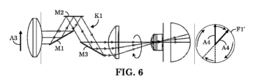
本願の回転装置はさらに、走査ビームを変化させる機構を備える。例えば、図6に示すように、KミラーK1の3つのミラーのうちの1つ(例えば、出力ミラーまたは射出光学要素M3)をオフセットすることによって、眼科撮像システムにおいて軸外スキャン(off-axis scan)を作成することができる。即ち、出力ミラーM3を(例えば、半径方向に)オフセットすることにより、出力画像の位置の(例えば、半径方向の)変位が生じる。このようにして、走査されたFOV F1’の直径は、元の(例えば、入力)走査ラインA3の長さの2倍まで拡張することができる。この場合、走査の有効FOVは2倍になる。ミラーM3がさらにオフセットされると、環状(例えば、ドーナツ状)の走査パターンを作成することができる。 The rotation device of the present application further includes a mechanism for varying the scanning beam. For example, as shown in FIG. 6, an off-axis scan can be created in an ophthalmic imaging system by offsetting one of the three mirrors of the K mirror K1 (e.g., the output mirror or exit optical element M3). That is, offsetting the output mirror M3 (e.g., radially) results in a (e.g., radial) displacement of the position of the output image. In this way, the diameter of the scanned FOV F1' can be expanded to twice the length of the original (e.g., input) scan line A3. In this case, the effective FOV of the scan is doubled. If the mirror M3 is offset further, an annular (e.g., donut-shaped) scan pattern can be created.
任意選択的に、Kミラーを用いた走査部品が、患者に固視標を提供するために使用されてもよい。例えば、可視光利用の場合、撮像走査を作動させる前に、可視光ラインビームをKミラーK1に入力して、患者の固視標を作成することができる。図7は、ミラーM3の適切なオフセット調整およびKミラーK1の回転速度によって作成され得る2つの例示的な固視標パターンT1およびT2を示す。このためには、Kミラーの回転速度をヒトの眼の感覚に応じて制御する必要があり得る。 Optionally, a scanning component using a K mirror may be used to provide a fixation target for the patient. For example, in the case of visible light applications, a visible light line beam can be input to the K mirror K1 to create a fixation target for the patient before activating the imaging scan. FIG. 7 shows two exemplary fixation target patterns T1 and T2 that can be created by appropriate offset adjustment of mirror M3 and the rotation speed of the K mirror K1. This may require that the rotation speed of the K mirror be controlled according to the sensitivity of the human eye.
第2の例として、視野計の固視標を提供するためにKミラーを使用することができる。この場合、患者には、様々な強度および/または大きさの一連の固視点が視野内の所定の位置に提示され、かつ固視点の出現または不存在を識別するように求められる。 As a second example, a K-mirror can be used to provide fixation targets for a perimeter. In this case, the patient is presented with a series of fixation points of various intensities and/or sizes at predetermined locations in the visual field and is asked to identify the appearance or absence of the fixation points.
代替的に、Kミラーは、複数の光ビーム出力を提供するために複数の入力を備えてもよく、そのうちの1つは、固視標を形成し得る。図8は、2つの入力光ビームB1およびB2を備えたKミラーモジュールの実施形態を示す。この場合、ミラーM1およびM2は、光ビームB1に対して反射性を有しており、かつ光ビームB2に対して透過性(例えば、透明性)を有している。このようにして、ミラーM1は、Kミラーへの2つの別個の入力経路を規定する。例えば、ミラーM1およびM2はダイクロイック表面を有しており、かつ所定の周波数の光に対して透過性を有している。例示的な動作では、ビームB1は、Kミラーによって回転または他の方法でシフトされ得るが、ビームB2は、Kミラーをそのまま通過し得る。本例では、光ビームB1およびB2が可視であってもよく(例えば、それぞれが個々の固視標を選択的に規定する)、または一方が走査ビームであり、他方が固視標を規定し得る。 Alternatively, the K mirror may have multiple inputs to provide multiple light beam outputs, one of which may form the fixation target. FIG. 8 shows an embodiment of a K mirror module with two input light beams B1 and B2. In this case, mirrors M1 and M2 are reflective to light beam B1 and transmissive (e.g., transparent) to light beam B2. In this way, mirror M1 defines two separate input paths to the K mirror. For example, mirrors M1 and M2 have dichroic surfaces and are transmissive to light of a given frequency. In an exemplary operation, beam B1 may be rotated or otherwise shifted by the K mirror, while beam B2 may pass through the K mirror intact. In this example, light beams B1 and B2 may be visible (e.g., each selectively defines an individual fixation target), or one may be a scanning beam and the other may define the fixation target.
図9は、ミラーM3が第1のビームB1に対して反射性を有しており、かつ第2のビームB2(例えば、可視光)に対して透過性を有している代替の実施形態を示す。このようにして、ミラーM3は、Kミラーへの第2の入力経路を規定する。本例では、第4のミラーM4は、固視発生器FG(例えば、第2の光源)からのビームB2を折り返して、ミラーM3を通過して出力して、患者に対する固視パターンを形成する。 Figure 9 shows an alternative embodiment in which mirror M3 is reflective to the first beam B1 and transmissive to the second beam B2 (e.g., visible light). In this way, mirror M3 defines a second input path to the K mirror. In this example, a fourth mirror M4 folds beam B2 from a fixation generator FG (e.g., a second light source) back through mirror M3 and out to form a fixation pattern for the patient.
図10は、ミラーM1がKミラーの内部に面する第1の表面上で反射性を有する(例えば、B1に対して反射性を有する)ため、図2~図7を参照して上記のように機能すること、かつ第1の表面の裏側にある第2の表面上で光ビームB2に対して透過性を有することの第3の代替の実施形態を示す。この第2の表面は、Kミラーモジュールへの第2の入力を構成すること、および固視入力を提供することのために使用され得る。例えば、固視光源FGは、ミラーM1の第2の入力面を介して固視ビームB2(例えば、ラインビーム)をKミラーに入力すること、およびミラーM2およびM3で反射して、患者に対する出力固視パターン(例えば、図7に示すような回転パターン)を生成することを行うことができる。この固視パターンは、撮像走査(例えば、ビームB1)の適用と同時に提供され得る。 Figure 10 shows a third alternative embodiment in which mirror M1 functions as described above with reference to Figures 2-7 by being reflective (e.g., reflective to B1) on a first surface facing the interior of the K mirror, and is transparent to light beam B2 on a second surface behind the first surface. This second surface may be used to constitute a second input to the K mirror module and to provide a fixation input. For example, a fixation light source FG may input a fixation beam B2 (e.g., a line beam) to the K mirror via the second input surface of mirror M1 and reflect off mirrors M2 and M3 to generate an output fixation pattern for the patient (e.g., a rotational pattern as shown in Figure 7). This fixation pattern may be provided simultaneously with the application of an imaging scan (e.g., beam B1).
上記の全ての実施形態において、固視光源FGは、任意選択的に、固視光源FGおよびKミラーが連動して移動/回転するように、Kミラーに機械的に固定され得る。このようにして、固視パターンは、撮像走査の適用中に、患者に対して比較的静的に出現し得る。 In all of the above embodiments, the fixation light source FG may optionally be mechanically fixed to the K mirror such that the fixation light source FG and the K mirror move/rotate in unison. In this way, the fixation pattern may appear relatively static to the patient during application of the imaging scan.
図11および図12は、固視発生器(第2の光源)の2つの例示的な構成を示す。図11において、固視発生器FGは、発光ダイオード(LED)の線形ストリップ(例示的に、7個のダイオードD1~D7を含むように示されている)を含み、それらの任意の組み合わせが選択的にオンされ得る。図示の例では、ダイオードD1、D3、D5、およびD7がオンされている。このパターンが回転のためにKミラーに送られると、結果的に得られる固視パターンは一連の同心円C1になる。代替的に、図12に示されているように、固視発生器FGは、円形に配置された複数のダイオードを含み得る。この構成では、走査ラインビームは、円形配置のダイオードの中心内で伝送され得る。この場合、円形パターンを作成するために固視ビームを回転させる必要はない。さらに代替的に、固視発生器は、図示しないダイオードの二次元アレイを含み、それによって複数の異なるパターンを形成することができる。この構成は、ダイオードの複数のストリップ(図11に示すような)を互いに隣接して配置することによって構成することができる。 11 and 12 show two exemplary configurations of the fixation generator (second light source). In FIG. 11, the fixation generator FG includes a linear strip of light emitting diodes (LEDs) (illustratively shown to include seven diodes D1-D7), any combination of which may be selectively turned on. In the illustrated example, diodes D1, D3, D5, and D7 are turned on. When this pattern is sent to the K mirror for rotation, the resulting fixation pattern is a series of concentric circles C1. Alternatively, as shown in FIG. 12, the fixation generator FG may include multiple diodes arranged in a circle. In this configuration, the scan line beam may be transmitted within the center of the circular arrangement of diodes. In this case, it is not necessary to rotate the fixation beam to create a circular pattern. In a further alternative, the fixation generator may include a two-dimensional array of diodes, not shown, thereby forming multiple different patterns. This configuration may be constructed by placing multiple strips of diodes (as shown in FIG. 11) adjacent to each other.
本願のKミラー構成は、回転走査を設ける代わりに、またはそれに加えて、直線的な走査(または横方向走査)を提供するようにさらに拡張され得る。例えば、撮像システムは、Kミラーを選択的に回転および/または並進させて、回転および/または並進の走査動作を切り替えるようにすることができる。 The K-mirror configuration of the present application may be further extended to provide linear scanning (or lateral scanning) instead of or in addition to providing rotational scanning. For example, the imaging system may selectively rotate and/or translate the K-mirror to switch between rotational and/or translational scanning motion.
Kミラーによる横方向ライン走査
網膜撮像では、ライン走査は、一般的に、瞳孔共役の近くに配置されたガルボミラーを使用して行われる。瞳孔共役の近くの空間が制限されているか、またはアクセスできない場合、網膜共役の近くで走査機構が実施されることが好ましい。これにより、別の瞳孔共役を作成するための追加の光リレーの必要性を回避することができる。
Lateral Line Scanning with K-Mirrors In retinal imaging, line scanning is typically performed using a galvo mirror placed near the pupil conjugate. When space near the pupil conjugate is limited or inaccessible, it is preferable to implement the scanning mechanism near the retinal conjugate. This avoids the need for an additional optical relay to create a separate pupil conjugate.
回転ビームを生成するためのプリズムの使用は、ドナルド・エル・サリバン(Donald L. Sullivan)による「回転プリズムの位置合わせ(Alignment of Rotational Prisms)」(アプライド・オプティクス(Applied Optics)、第11巻、第9号、1972年9月)、およびリウ(Liu)他による「ポロプリズムのフィールド回転および偏光特性(Field Rotation and Polarization Properties of the Porro Prism)」(ジャーナル・オブ・ザ・オプティカル・ソサエティ・オブ・アメリカ・エー(J.Opt.Soc.Am.A)、第26巻、第5号、2009年5月)に記載されている。しかしながら、走査機構としての機能は十分に検討されていない。米国特許第7,463,394号明細書は、走査目的でのルーフプリズムの使用について説明しているが、2つの互いに垂直な反射面を有するプリズムに限定されている。さらに重要なことは、上記したように、プリズムを通過する光がコリメートされていない場合、プリズムは望ましくない収差を生成する可能性があるということである。従って、プリズムは、眼科撮像システムのビームが(コリメートされていない状態で)合焦される網膜共役またはその近傍に配置される走査部品としては適していない。ミラーを使用した点回転走査の例は、スティールマン(Steelman)による「角度分解低コヒーレンス干渉測定のための走査方式」(オプティクス・レターズ(Opt Lett.)、2017年11月15日、42(22)、4581-4584)に記載されている。しかしながら、サリバンが説明しているように、回転走査機構の位置合わせは困難である。横方向(または並進または一次元)の走査機構は、これらの課題のいくつかを回避すること、および位置合わせがより容易になることがあり得る。従って、横方向の走査機構のオプションが利用可能であれば、いくつかの用途において好ましい場合がある。本明細書では、簡略化された横方向の走査機構を実現するためにKミラーを使用する走査機構が提示されている。 The use of prisms to generate rotating beams has been described in "Alignment of Rotational Prisms" by Donald L. Sullivan (Applied Optics, Vol. 11, No. 9, September 1972) and "Field Rotation and Polarization Properties of the Porro Prism" by Liu et al. (J. Opt. Soc. Am. A, Vol. 26, No. 5, May 2009). However, their function as a scanning mechanism has not been fully explored. U.S. Pat. No. 7,463,394 describes the use of roof prisms for scanning purposes, but is limited to prisms with two mutually perpendicular reflecting surfaces. More importantly, as noted above, prisms can produce undesirable aberrations if the light passing through them is not collimated. Thus, prisms are not suitable as scanning components located at or near the retinal conjugate where the beam of an ophthalmic imaging system is focused (uncollimated). An example of point rotation scanning using mirrors is described in Steelman, "Scanning Schemes for Angle-Resolved Low Coherence Interferometry," Opt Lett., Nov. 15, 2017, 42(22), 4581-4584. However, as Sullivan explains, alignment of a rotational scanning mechanism is difficult. A lateral (or translational or one-dimensional) scanning mechanism may avoid some of these challenges and may be easier to align. Therefore, the availability of a lateral scanning option may be preferable in some applications. A scanning mechanism using K mirrors to achieve a simplified lateral scanning mechanism is presented herein.
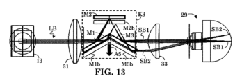
図13は、横方向の走査を実現するために一次元に沿って(矢印A5に沿って)並進されるKミラーモジュールK3を示す。本実施形態では、KミラーK3は、走査レンズ31と接眼レンズ33との間の網膜共役に、またはその近傍に配置される。説明のために、光源13は、走査レンズ31(または任意選択に対物レンズ)を通過する照明ラインビームLBであって、走査部品(例えば、KミラーK3)を介して、変位した走査ビームSB1およびSB2によって示されるように、眼29の網膜を走査するように接眼レンズ33を通過する照明ラインビームLBを提供するように示されている。説明のために、ミラーM1、M2、およびM3が第1の位置に示されており、ミラーM1b、M2b、およびM3bが矢印A5に沿って直線的に変位した第2の位置に示されている。KミラーK3がミラーM1、M2、およびM3によって示される第1の位置にあるとき、ラインビームLBはミラーM1からミラーM2に反射した後、ミラーM3に戻って、射出走査ビームSB1を形成する。同様に、KミラーがミラーM1b、M2b、およびM3bによって示される第2の位置にあるとき、ラインビームLBは、ミラーM1b上の第2のオフセット位置からミラーM2bで反射した後、ミラーM3bに戻って、射出走査ビームSB2を形成する。KミラーK3に往復運動を適用することにより、ラインビームSBは、眼29の網膜上で一次元に沿って走査されて、一次元の横方向の走査を実現することができる。この横方向の走査機構は、網膜共役においてスキャナが必要な場合にも対処しており、かつミラーリフレクタを使用することで、プリズムの望ましくない収差および分散特性を軽減することができる。さらに、本願の横方向の走査機構は、回転走査機構よりも位置合わせがより容易であり得る。
13 shows the K-mirror module K3 being translated along one dimension (along arrow A5) to achieve lateral scanning. In this embodiment, the K-mirror K3 is located at or near the retinal conjugate between the
図14Aおよび図14Bは、横方向ライン走査のためにKミラーK3(矢印A6に沿って直線的に並進される)を使用したより詳細なゼマックス(Zemax(登録商標))シミュレーションを示す。図14Aは、一例としてラインフィールド方式(例えば、ラインビーム)を使用することを示す。KミラーK3を網膜共役面において+/-mmだけシフトすると、走査ビームSB1~SB5によって示されるように、網膜において水平方向に8mmにわたってライン照明が走査される。走査された網膜の正面平面図30は、Kミラーの(直線的な)並進運動によって生成される、異なる走査位置における5個のライン走査ビームSB1~SB5を示す。説明を簡単にするために、図14Bは、網膜上の5つの異なる走査位置において5個の走査ビームSB1、SB2、SB3、SB4、およびSB5を形成するKミラーの5つの個別の横方向/シフト位置を示す。 14A and 14B show a more detailed Zemax® simulation using K-mirror K3 (linearly translated along arrow A6) for lateral line scanning. FIG. 14A shows the use of a line field approach (e.g., line beam) as an example. Shifting K-mirror K3 by +/- mm in the retina conjugate plane scans the line illumination horizontally across 8 mm on the retina, as shown by scanning beams SB1-SB5. A front plan view 30 of the scanned retina shows five line scanning beams SB1-SB5 at different scanning positions, generated by the (linear) translation of the K-mirror. For ease of illustration, FIG. 14B shows five separate lateral/shift positions of the K-mirror forming five scanning beams SB1, SB2, SB3, SB4, and SB5 at five different scanning positions on the retina.
KミラーK3のように、ミラーリフレクタまたは反射面を使用することにより、プリズムによってコリメートされていない光ビームに導入される望ましくない収差が除去される。収差がないため、この手法は、ビームが典型的にはコリメートされない網膜共役における走査機構として好適である。網膜共役面の近くのスキャナは、瞳孔共役面へのアクセスが制限されているか、または利用できない場合に有用である。また、本実施形態は、本明細書で提案されるKミラーがルーフ構造を有していないため、米国特許第7,463,394号明細書に記載されるようなルーフ構造は、横方向の走査のためのビーム変位を生成するために必要ではないことを示す。本実施形態の別の利点は、横方向の走査が、回転方向の走査と比較して、一般的に位置合わせがより簡単であることである。 The use of a mirror reflector or reflective surface, such as the K mirror K3, eliminates the undesirable aberrations introduced by prisms into uncollimated light beams. The lack of aberrations makes this approach suitable as a scanning mechanism at the retina conjugate, where the beam is typically uncollimated. A scanner near the retina conjugate plane is useful when access to the pupil conjugate plane is limited or unavailable. This embodiment also shows that a roof structure, such as that described in U.S. Pat. No. 7,463,394, is not necessary to generate beam displacement for lateral scanning, since the K mirror proposed herein does not have a roof structure. Another advantage of this embodiment is that lateral scanning is generally easier to align compared to rotational scanning.
横方向の走査のための複数の反射面を備えた他のミラー組立体が可能であり得る。一般に、ミラーシステムを介した奇数回の反射は、同じ方向に沿ってビームを変位させることができ、偶数回の反射は、その逆方向に沿ってビームを変位させることができる。ミラーモジュールが第1の量だけ横方向にシフトすると、第2の量の出力走査ビームの乗法的な横方向の変位/シフト/走査(例えば、2倍以上)を生じさせることができる。 Other mirror assemblies with multiple reflective surfaces for lateral scanning may be possible. In general, an odd number of reflections through the mirror system can displace the beam along the same direction, and an even number of reflections can displace the beam along the opposite direction. A lateral shift of the mirror module by a first amount can result in a multiplicative lateral displacement/shift/scan of the output scanning beam by a second amount (e.g., two times or more).
Kミラーを並進させると、1つの対応する次元の横方向の走査が行われるが、複数のKミラーを組み合わせて二次元以上の走査を行うことも可能である。例えば、2つのKミラーを垂直な走査軸と組み合わせることで、二次元の走査を実現することができる。しかしながら、この構造の走査速度は、ミラー組立体の並進に関連する速度制限によって制限される場合がある。 Translating a K mirror provides lateral scanning in one corresponding dimension, although multiple K mirrors can be combined to provide scanning in more than one dimension. For example, two K mirrors can be combined with perpendicular scan axes to provide two-dimensional scanning. However, the scanning speed of this configuration may be limited by speed limitations associated with translating the mirror assembly.
Kミラーの横方向の走査は、他の走査方法と組み合わせることも可能である。例えば、図15は、瞳孔共役に配置された第1の部分と、網膜共役に配置された第2の部分とを有する、2部分からなる走査機構を示す。本実施形態では、KミラーK4は、網膜共役に、またはその近傍に配置され、かつ低速軸走査に使用される。ガルボスキャナG1は瞳孔共役の近くに配置され、かつ高速軸走査に使用される。例えば、走査点が水平方向に走査されて走査点の行を形成した後、走査点が垂直方向に新たな行の位置にシフトされる二次元の点走査の場合、水平方向の走査は高速軸走査であり、垂直方向の走査は低速軸走査である。この実施形態では、システム統合を容易にするために、2つのスキャナ(K4およびG1)が空間内で分離されている。この実施形態は、また、走査ピボット点(またはガルボG1)が実質的に瞳孔共役にあることを可能にするが、これは、例えば、図1に示されるように、2つのガルボスキャナが1つの瞳孔共役にある必要がある場合には実現するのが困難である。 The lateral scanning of the K mirror can also be combined with other scanning methods. For example, FIG. 15 shows a two-part scanning mechanism with a first part located at the pupil conjugate and a second part located at the retina conjugate. In this embodiment, the K mirror K4 is located at or near the retina conjugate and is used for the slow axis scanning. The galvo scanner G1 is located near the pupil conjugate and is used for the fast axis scanning. For example, in the case of two-dimensional point scanning where the scanning points are scanned horizontally to form a row of scanning points and then shifted vertically to a new row position, the horizontal scanning is the fast axis scanning and the vertical scanning is the slow axis scanning. In this embodiment, the two scanners (K4 and G1) are separated in space to facilitate system integration. This embodiment also allows the scanning pivot point (or galvo G1) to be substantially at the pupil conjugate, which is difficult to achieve when two galvo scanners need to be at one pupil conjugate, for example, as shown in FIG. 1.
Kミラーのための複数の異なる並進機構が本発明に適している。図16Aおよび図16Bは、誘導アクチュエータ61を使用する第1のKミラー並進機構を示す。
本手法では、誘導アクチュエータ61は、平行屈曲部(例えば、等方性ばね)63と組み合わされ、各々が矢印A7およびA8によって示される相反する力を提供する。図16Bに示されるように、誘導アクチュエータ61が適切な電流iの印加などによって作動/起動されると、支持バー62(および取り付けられたKミラーK5)を移動させて比例並進オフセットΔxを生じさせる力が生成される。逆に、誘導アクチュエータ61が作動されなくなるか、またはその印加電流iが減少されると、平行屈曲部63のばね力により、KミラーK5が反対方向に移動して、オフセットΔxが除去または減少される。誘導アクチュエータ61は、機械的アクチュエータと比較してより静的動作を提供し得る。平行屈曲部63により、コンパクトな直列配置が可能になる。また、変位は電流の関数Δx=f(i)であるため、エンコーダが不要になる。これは、誘導アクチュエータ61が、変位Δxに比例する力Fk(例えば、Fk(Δx)=kΔx、式中、kはばね定数)を発揮するばねと共に作用する、電流iの関数Fi(i)である力Fiを発揮するためである。平衡状態では、Fi(i)=Fk(Δx)=kΔxであるため、変位(Δx=Fi(i)/k)は電流iの関数である。
A number of different translation mechanisms for the K mirror are suitable for the present invention. Figures 16A and 16B show a first K mirror translation mechanism that uses an
In this approach, the
図17は、偏心を備えたモータ65(例えば、オフセンタホイール/ディスク67)を使用してKミラーK5を移動させ、それによって平行屈曲部63を所与のオフセットΔxだけ変形させる代替の並進機構を示す。モータ65によって回転される物体(例えば、ホイールまたはディスク67)は、回転中心に対して非対称であるため、その回転により、KミラーK5を押圧することなどによって、隣接する平行屈曲部63の並進を引き起こすことができる。モータ65によって回転される物体67は、ディスクである必要はない。所望の走査速度および/またはパターンを提供するために、任意の形状(例えば、水滴形状)を設計することができる。
Figure 17 shows an alternative translation mechanism using a motor 65 with eccentricity (e.g., an off-center wheel/disk 67) to move the K mirror K5, thereby deforming the
以上説明したように、本発明は、走査部品(例えば、Kミラー)を網膜共役に配置することを可能にするため、それを瞳孔分割機能に使用することはできない。従って、本発明は、特別なサイズおよび形状の静止ビームスプリッタが瞳孔共役に配置されており、かつ瞳孔分割機能を提供するように使用されることを提案する。瞳孔分割機能を実施するための瞳孔共役におけるビームスプリッタの位置決めは、ビームスプリッタが静止しているために容易になり、これにより、眼科撮像システムの組み立てがさらに簡略化される。以下でさらに詳しく説明するように、この構成は、OCT/OCTAなどの干渉測定への応用にさらなる利点を提供する。 As explained above, the present invention allows for the placement of a scanning component (e.g., a K mirror) at the retina conjugate, so that it cannot be used for the pupil splitting function. Therefore, the present invention proposes that a specially sized and shaped stationary beam splitter is placed at the pupil conjugate and used to provide the pupil splitting function. Positioning of the beam splitter at the pupil conjugate to perform the pupil splitting function is facilitated because the beam splitter is stationary, which further simplifies the assembly of the ophthalmic imaging system. As explained in more detail below, this configuration provides additional advantages for interferometric applications such as OCT/OCTA.
効率的な干渉測定のためのビームスプリッタ設計
説明を容易にするために、本実施形態は、OCTシステムに適用されるものとして説明されるが、同様の瞳孔分割機能が、眼底撮像装置またはOCTAシステムに適用され得ることを理解されたい。また、説明を容易にするために、本実施形態は、図1のOCT例を参照して上記したように、関連する構成要素に焦点を合わせるが、ラインフィールドまたはフルフィールド撮像などの特定のフィールド構成用に構成されている。ラインフィールド撮像の実施形態を最初に説明した後、フルフィールド撮像に適用される本発明の利点について説明する。本発明は、他のライトフィールド構成に適用され得ることが理解されるべきである。
Beam splitter design for efficient interferometric measurements For ease of explanation, the present embodiment is described as applied to an OCT system, but it should be understood that a similar pupil splitting function may be applied to a fundus imager or OCTA system. Also, for ease of explanation, the present embodiment focuses on the relevant components as described above with reference to the OCT example of FIG. 1, but is configured for a particular field configuration, such as line field or full field imaging. An embodiment of line field imaging will be described first, followed by a description of the advantages of the present invention as applied to full field imaging. It should be understood that the present invention may be applied to other light field configurations.
図18は、ラインフィールド眼科撮像システムで使用され得る3つのビームスプリッタ構成を示す。同様の構成が、フルフィールド眼科撮像システムで使用され得ることを理解されたい。第1のビームスプリッタ構成は、「従来の軸上(Conventional On-Axis)」構成と呼ばれ得る。第1のビームスプリッタ構成は、ビームスプリッタBSを、サンプル(例えば、眼)に対する照明/集光光軸上に中心として置くとともに、眼に対する照明(光)信号/ビームLtB(ここでは走査ラインSLとして図示されている)の光路全体およびサンプルからの集光信号/ビームCB全体に及ぶ。サンプルビームSBは、撮像されるサンプル(例えば、システムのサンプルアーム)、例えば、被検眼に向けられる。集光ビームのFOV(例えば、集光器から見た場合)は、ここでは円形の集光ウィンドウCWとして図示されている。この従来の軸上構成では、集光信号CBの全体が集光器に向かう途中でビームスプリッタBSを通過するため、集光ビームCBの全体が集光器に向かう途中でビームスプリッタBSによって減衰されることを示すために、集光ウィンドウCWは完全に暗く示されている。完全を期すために、システムの瞳ストップPS(例えば、物理的アパーチャストップ)も示されている。瞳ストップPSは、撮像される眼の瞳孔共役に配置され得る。この場合、瞳ストップPSは集光ウィンドウCWを形成するのに役立ち得る。 Figure 18 shows three beam splitter configurations that may be used in a line-field ophthalmic imaging system. It should be understood that similar configurations may be used in a full-field ophthalmic imaging system. The first beam splitter configuration may be referred to as a "Conventional On-Axis" configuration. The first beam splitter configuration centers the beam splitter BS on the illumination/collection optical axis for the sample (e.g., eye) and spans the entire optical path of the illumination (light) signal/beam LtB (here illustrated as a scan line SL) for the eye and the entire collected signal/beam CB from the sample. The sample beam SB is directed toward the sample to be imaged (e.g., the sample arm of the system), e.g., the subject's eye. The FOV of the collected beam (e.g., as seen from the collector) is illustrated here as a circular collection window CW. In this conventional on-axis configuration, the entire collected signal CB passes through the beam splitter BS on its way to the collector, so the collection window CW is shown completely dark to indicate that the entire collected beam CB is attenuated by the beam splitter BS on its way to the collector. For completeness, the pupil stop PS of the system (e.g., a physical aperture stop) is also shown. The pupil stop PS may be placed at the pupil conjugate of the imaged eye. In this case, the pupil stop PS may help to form the collection window CW.
第2の構成は、「軸外(Off-Axis)」構成と呼ばれ得る。第2の構成は、ビームスプリッタBSが戻り集光ビームCBの光路の一部(例えば、約半分)のみに及ぶようにビームスプリッタBSを照明/集光光軸から変位させる。この構成では、集光ウィンドウCWの一部は、ビームスプリッタSBを通過する集光ビームCBの一部に対応して暗く示されており、集光ウィンドウCWの残りは、ビームスプリッタBSの平面の上を通過するが、ビームスプリッタを通過しないため、ビームスプリッタBSによって減衰されない集光ビームCBの一部を強調するために白く示されている。この場合、ライン走査LS(例えば、照明ビームLtB)の焦点は、集光ウィンドウの暗い部分内に示されている。 The second configuration may be referred to as the "Off-Axis" configuration. The second configuration displaces the beam splitter BS from the illumination/collection optical axis such that it spans only a portion (e.g., about half) of the optical path of the return collection beam CB. In this configuration, a portion of the collection window CW is shown dark corresponding to the portion of the collection beam CB that passes through the beam splitter SB, and the remainder of the collection window CW is shown white to highlight the portion of the collection beam CB that passes above the plane of the beam splitter BS but does not pass through the beam splitter and is therefore not attenuated by the beam splitter BS. In this case, the focus of the line scan LS (e.g., illumination beam LtB) is shown within the dark portion of the collection window.
第3の構成は、本明細書では「光フットプリント-BS軸上(Light-Footprint-BS On-Axis)」と呼ばれ得る。第3の構成は、照明ビームLtBの光フットプリントに合わせた形状のビームスプリッタBSを使用する。このラインフィールドの例では、光フットプリント-BS軸上構成のビームスプリッタBSは、面積(または寸法)が入射照明光LtBの光フットプリントに適合しており、かつ入射照明光LtBよりもわずかに大きい細長いスリット(または長方形)として形成され得る。この場合、集光ビームのほとんどがビームスプリッタBSの上下を減衰することなく通過するため、集光ウィンドウCWは、ほとんどが白く示されている。ライン走査LS(例えば、照明ビームLtB)の焦点におけるビームスプリッタBSの位置に対応する集光ウィンドウCWの中央領域のみが暗く示されている。 The third configuration may be referred to herein as "Light-Footprint-BS On-Axis." The third configuration uses a beam splitter BS shaped to match the light footprint of the illumination beam LtB. In this line field example, the beam splitter BS in the Light-Footprint-BS On-Axis configuration may be formed as an elongated slit (or rectangle) whose area (or dimensions) match the light footprint of the incident illumination light LtB and are slightly larger than the incident illumination light LtB. In this case, the collection window CW is shown mostly white because most of the collected light beam passes unattenuated above and below the beam splitter BS. Only the central region of the collection window CW, which corresponds to the position of the beam splitter BS at the focus of the line scan LS (e.g., illumination beam LtB), is shown dark.
従来の軸上構成を用いたラインフィールドOCTでは、図1を参照して上記したように、干渉計内のビームスプリッタ(BS)は、一般的には、光学面全体で均一なビーム分割比を有するプレート型またはキューブ型のビームスプリッタである。この典型的な例では、ビームスプリッタは、限られた量のサンプル光SBをサンプル(例えば、眼底)に向けて案内すること、およびサンプルからの後方散乱光信号CBを減衰させることを行うため、検出感度が制限される。例えば、従来の軸上構成では、照明ビームLtBはビームスプリッタBSを2回通過する(1回は参照ビームRBとサンプルビームSBに分割されるときであり、もう1回は集光ビームCBがサンプルから戻ってくるときである)。50/50のビームスプリッタの場合、これは、照明光LtBの75%が失われることを意味する(各経路で50%)。このパワーの非効率性は、特に、光源パワーおよび眼に許容される光パワーが制限されている場合には望ましくない。プローブ光(例えば、サンプル光SB)をサンプルに向かって効率的に誘導して、サンプルから戻る後方散乱光CBを効率的に集光する方法が必要とされる。 In line-field OCT using a conventional on-axis configuration, as described above with reference to FIG. 1, the beam splitter (BS) in the interferometer is typically a plate or cube type beam splitter with a uniform beam splitting ratio across the entire optical surface. In this typical example, the beam splitter guides a limited amount of sample light SB toward the sample (e.g., fundus) and attenuates the backscattered light signal CB from the sample, limiting the detection sensitivity. For example, in a conventional on-axis configuration, the illumination beam LtB passes through the beam splitter BS twice (once when it is split into the reference beam RB and the sample beam SB, and once when the collected beam CB returns from the sample). For a 50/50 beam splitter, this means that 75% of the illumination light LtB is lost (50% on each path). This power inefficiency is undesirable, especially when the light source power and the optical power allowed by the eye are limited. What is needed is a method to efficiently direct the probe light (e.g., sample light SB) toward the sample and efficiently collect the backscattered light CB returning from the sample.
これまでにも効率改善は提案されている。偏光を用いた手法は、(本出願と同じ譲受人に譲渡された)米国特許第7145661号明細書および米国特許第9778020号明細書に記載されている。この手法では、プローブビーム経路内の偏光BSと偏光回転子を非相互的なビーム分割器として使用することにより、後方散乱光の偏光を回転させ、偏光ビームスプリッタを効率的に通過させることができる。しかしながら、サンプルの複屈折により、後方散乱光の偏光状態がすでに変化している可能性があるため、効率が低下する。また、偏光光学系は一般的に高コストであるため、低コストのデバイスには適さない。軸外検出方法は、共同所有の米国特許出願公開第2018/0259316号に記載されている。米国特許出願公開第2018/0259316号では、プローブ光のより効率的な誘導と信号光のより高いスループットを可能にするように、ビームスプリッタが集光瞳を部分的に覆うように配置されている。しかしながら、この手法でも、集光瞳および信号光の大部分が遮断される。さらに、ビームスプリッタは、光センサまたはカメラの集光瞳共役にあるため、(眼の)瞳孔分割機能を提供することはできない。別の手法は、例えば、米国特許第7648242および6758564号明細書に記載されているように、ライン走査の走査型レーザー検眼鏡(SLO:scanning laser ophthalmoscope)においてアパーチャミラー/ビームスプリッタを使用するが、これまで、アパーチャビームスプリッタのいかなる利点も干渉測定に対して完全には実現されていない。別の手法は、上記した自由空間のビームスプリッタ構成に代えて、特殊なファイバカプラを使用することである。例えば、ファイバを用いた光サーキュレータの実施は、米国特許第7362444号明細書に記載されているような点走査(例えば、点フィールド)OCTに関連して説明されているが、この手法は、ラインフィールドOCTには適用できず、コストを増加させる。 Efficiency improvements have been proposed in the past. Polarized light techniques are described in U.S. Pat. No. 7,145,661 and U.S. Pat. No. 9,778,020 (assigned to the same assignee as the present application). In this technique, a polarizing beam splitter and a polarization rotator in the probe beam path are used as a non-reciprocal beam splitter to rotate the polarization of the backscattered light and allow it to pass efficiently through the polarizing beam splitter. However, due to birefringence in the sample, the polarization state of the backscattered light may already have been changed, reducing efficiency. Also, the high cost of polarized optics is generally not suitable for low-cost devices. An off-axis detection method is described in co-owned U.S. Pat. App. Pub. No. 2018/0259316. In U.S. Pat. App. Pub. No. 2018/0259316, the beam splitter is positioned to partially cover the collection pupil, allowing for more efficient steering of the probe light and higher throughput of the signal light. However, this technique still blocks the collection pupil and most of the signal light. Furthermore, the beam splitter cannot provide a pupil splitting function (of the eye) since it is at the collection pupil conjugate of the optical sensor or camera. Another approach is to use an aperture mirror/beam splitter in a line-scanning scanning laser ophthalmoscope (SLO), as described, for example, in U.S. Pat. Nos. 7,648,242 and 6,758,564, but to date, any advantages of the aperture beam splitter have not been fully realized for interferometric measurements. Another approach is to use a specialized fiber coupler instead of the free-space beam splitter configuration described above. For example, the implementation of an optical circulator using fiber has been described in the context of point-scanning (e.g., point-field) OCT, as described in U.S. Pat. No. 7,362,444, but this approach is not applicable to line-field OCT and increases costs.
本願の手法では、軸外構成は、後方散乱集光光CBの一部がビームスプリッタと同じ平面(例えば、同じ(眼の)瞳孔共役平面)を通過することを可能にするが、ビームスプリッタを通過することを回避する。さらに、物理的アパーチャストップ(または瞳ストップ)PSは、別の(眼の)瞳孔共役面に配置され、かつ(眼の)瞳孔分割領域を形成するのに役立つように構成され得る。ビームスプリッタと組み合わせた物理的アパーチャの使用により、瞳孔分割機能が提供され得る。さらに、以下で説明するように、瞳ストップの形状は、より軸方向の高い深度分解能および/または光強度および横方向の分解能などの特定の撮像の必要性に応じて選択することができる。この例では、瞳ストップPSは、ビームスプリッタの大部分の領域を遮断するように形成されている。 In the present approach, the off-axis configuration allows some of the backscattered collected light CB to pass through the same plane as the beam splitter (e.g., the same (eye) pupil conjugate plane), but avoids passing through the beam splitter. Additionally, a physical aperture stop (or pupil stop) PS may be located at another (eye) pupil conjugate plane and configured to help form the (eye) pupil splitting region. The use of a physical aperture in combination with a beam splitter may provide a pupil splitting function. Additionally, as described below, the shape of the pupil stop may be selected depending on the particular imaging needs, such as higher axial depth resolution and/or light intensity and lateral resolution. In this example, the pupil stop PS is shaped to block most of the area of the beam splitter.
ラインフィールドOCTシステムでは、照明ビームLtBは、ビームスプリッタの1つの次元/方向(例えば、ライン走査LSの幅寸法に沿った)において合焦され(コリメートされていない状態で)、直交する次元(例えば、ライン走査LSの長さ寸法に沿って)においてコリメートされていない状態に維持される。この照明は、システム内の瞳において、かつ物体面においてそれぞれ相互に垂直なラインを形成する。光フットプリント-BS軸上構成では、ビームスプリッタBSは、照明ビームLtBが合焦される寸法が狭い光学面を有するスリットビームスプリッタ(スリットBS)であり得るとともに、システムの機械的/動作公差によって決定されるビーム幅の数倍(例えば、10倍)程度の狭さであり得る。また、スリットビームスプリッタは、走査ラインに沿った寸法がより広い光学面を有し得る。この場合も、ビームスプリッタは、(眼の)瞳孔共役面に、またはその近傍に配置することができる。また、このスリットビームスプリッタは、光源光LtBの大部分をサンプルに向けて導くための高い反射透過率(例えば、10/90)と、スリットビームスプリッタによる遮断または減衰なしに(または最小限の遮断または減衰を伴う)集光信号光CBに対する高いスループットとを有することができる。10/90の反射透過率は、光信号ビームがビームスプリッタを通過するたびに90%減衰することを意味するため、これはサンプルから戻ってくる集光信号CBを大幅に減少させることから、通常、従来の軸上方式には適していない。しかしながら、本願の光フットプリント-BS軸上構成では、戻ってくる集光信号光CBのほとんどがスリットBSを通過せず、従ってその90%の減衰を受けないため、高い反射透過率が可能となる。50/50のビーム分割比を備えた従来の軸上設計と比較して、本願のスリットビームスプリッタは約6dBの感度改善を提供することができる。また、他の設計と比較して、(光フットプリント-BS軸上構成の)スリットビームスプリッタは、ラインフィールド干渉測定における全ての局面(照明、集光、参照)において必要な光のみを効率的に誘導する相互部品である。 In a line-field OCT system, the illumination beam LtB is focused (uncollimated) in one dimension/direction of the beam splitter (e.g., along the width dimension of the line scan LS) and remains uncollimated in the orthogonal dimension (e.g., along the length dimension of the line scan LS). This illumination forms mutually perpendicular lines at the pupil and at the object plane in the system, respectively. In the light footprint-BS on-axis configuration, the beam splitter BS can be a slit beam splitter (slit BS) with a narrow optical surface in the dimension in which the illumination beam LtB is focused, and can be as narrow as several times (e.g., 10 times) the beam width as determined by the mechanical/operational tolerances of the system. The slit beam splitter can also have a wider optical surface in the dimension along the scan line. Again, the beam splitter can be located at or near the pupil conjugate plane (of the eye). Also, the slit beam splitter can have a high reflection transmittance (e.g., 10/90) to direct most of the source light LtB toward the sample, and a high throughput for the collected signal light CB without (or with minimal) blocking or attenuation by the slit beam splitter. A reflection transmittance of 10/90 means that the optical signal beam is attenuated by 90% every time it passes through the beam splitter, which is usually not suitable for a conventional on-axis scheme since it greatly reduces the collected signal light CB returning from the sample. However, in the present optical footprint-BS on-axis configuration, a high reflection transmittance is possible because most of the returning collected signal light CB does not pass through the slit BS and therefore does not experience its 90% attenuation. Compared to a conventional on-axis design with a 50/50 beam splitting ratio, the present slit beam splitter can provide a sensitivity improvement of about 6 dB. Also, compared to other designs, the slit beam splitter (in the optical footprint - BS on-axis configuration) is an interactive component that efficiently directs only the light required for all aspects of line field interferometry (illumination, collection, referencing).
有利には、本願の眼科撮像システムは、軸外構成と光フットプリント-BS軸上構成とを切り替えるように構成されてもよい。即ち、瞳ストップPSを変化させることによって、機器は、光学系を変更することなく、軸上動作と軸外動作とを切り替えることができる。どちらのモードにも独自の利点を有するため、この柔軟性により、デバイスは幅広い用途に対応することができる。スリットビームスプリッタは、低空間周波数の信号光を遮断すること、およびバックグラウンド信号と照明信号とを明確に分離することが可能である。 Advantageously, the present ophthalmic imaging system may be configured to switch between an off-axis configuration and a light footprint-BS on-axis configuration. That is, by varying the pupil stop PS, the instrument can switch between on-axis and off-axis operation without changing the optics. This flexibility allows the device to accommodate a wide range of applications, as both modes have their own advantages. The slit beam splitter is capable of blocking low spatial frequency signal light and clearly separating background and illumination signals.
この機能は、パルス調整型ダイオードレーザーなど、光源スペクトルが変動するシステムにおいて有用である。低空間周波数の遮断により、角膜反射を除去することもできる。軸上設計は、軸外方式と比較して実施が容易であり、スリットBSは、偏光を用いた方法と比較して低コストである。さらに、スリットビームスプリッタによって、同じ構成でライン走査の走査レーザー検眼鏡(SLO)が可能となり、これは、ミラーの穴では実現できない。 This feature is useful in systems with varying light source spectra, such as pulsed diode lasers. Low spatial frequency cutoff also eliminates corneal reflections. On-axis designs are easier to implement compared to off-axis approaches, and slit BSs are less expensive compared to polarized light approaches. Additionally, slit beam splitters allow line-scanning scanning laser ophthalmoscopy (SLO) with the same configuration, which is not possible with holes in mirrors.
図19は、ラインフィールドSDOCTシステムにおける光フットプリント-BS軸上構成の簡略化された概略図を示す。スリットビームスプリッタ(スリットBS)は、瞳孔共役面またはその近傍に配置される。光フットプリント-BS軸上設計により、照明(サンプル)ビームSBを効率的に誘導すること、および集光ビームCBの減衰または遮断を最小限に抑えることが可能となる。上述したように、集光ビームCBおよび戻り参照ビームRBは、アパーチャ39を通過して、分光器で構成され得る集光器41に到達する。回折格子40は、入射光を異なる周波数成分に分離するものであり、光センサ42は、結果として生じるスペクトルをキャプチャする。 Figure 19 shows a simplified schematic diagram of the optical footprint-BS on-axis configuration in a line-field SDOCT system. The slit beam splitter (slit BS) is placed at or near the pupil conjugate plane. The optical footprint-BS on-axis design allows for efficient steering of the illumination (sample) beam SB and minimal attenuation or blockage of the collected beam CB. As mentioned above, the collected beam CB and the return reference beam RB pass through an aperture 39 to a collector 41, which may consist of a spectrometer. A diffraction grating 40 separates the incident light into different frequency components, and a photosensor 42 captures the resulting spectrum.
図20は、ラインフィールドの用途に適した光フットプリントビームスプリッタの第1の構造を示す。製造に関して、スリットBSは、より大きな基板64上のスリット状コーティング62であり得る。例えば、スリットBSは、薄いガラス基板66上のスリット状コーティングからなり得る。代替的に、スリットBSは、均一にコーティングされた薄いストライプ66の基板であり得る。基板は、プレートまたはプリズムであってもよく、コーティング表面は、2つの基板の間に挟まれていてもよい。
Figure 20 shows a first structure of an optical footprint beam splitter suitable for line field applications. In terms of fabrication, the slit BS can be a slit-
図21は、照明光が点またはドットまたは小さな2D領域に合焦されるフルフィールドまたはパーシャルフィールドの用途での使用に適した光フットプリントBSの第2の構造を示す。この場合、照明光フットプリントによって決定されるサイズのドット状(例えば、円形)ビームスプリッタ68が使用され得る。ドット状のビームスプリッタ68は、より大きな基板64上にコーティングされ得るか、または均一にコーティングされた一片の円形状の基板70であり得る。ドット状のビームスプリッタ68は、瞳孔共役面における二次元の小領域となる。
Figure 21 shows a second configuration of the light footprint BS suitable for use in full-field or partial-field applications where the illumination light is focused to a point or dot or small 2D region. In this case, a dot-like (e.g., circular)
図22は、透明基板(例えば、薄いガラス基板64)上の小面積コーティングを含む代わりに、本願のビームスプリッタの代替構成を示しており、そのビームスプリッタは、全反射基板上のコーティングとして構築されており、照明光LtBは、ビームスプリッタを通過してサンプルアーム上にサンプルビームSBを形成するとともに、ビームスプリッタによって折り返されて、参照アーム上に参照ビームRBを形成する。 Figure 22 shows an alternative configuration of the beam splitter of the present application, in which, instead of including a small area coating on a transparent substrate (e.g., a thin glass substrate 64), the beam splitter is constructed as a coating on a totally reflective substrate, and the illumination light LtB passes through the beam splitter to form a sample beam SB on the sample arm and is folded back by the beam splitter to form a reference beam RB on the reference arm.
空間周波数分析のみならず、効率的な照明および集光の同様の利点は、これら全てのビームスプリッタ構成に適用される。
典型的には、眼の網膜の深度情報を復元するために、(例えば、光センサ42によってキャプチャされた)スペクトルに1D FFTを適用することとなる。しかしながら、キャプチャされたスペクトルに2D FFTを最初に適用することにより、瞳孔共役における空間的なスペクトル分布を復元することができる。例えば、図23は、光フットプリント-BS軸上手法を使用して取得され得るスペクトル71と、スペクトル71に1D FFTを適用することによって構築され得る代表的な網膜73とを示す。図24は、同じスペクトル71を示しているが、2D FFTを適用すると、空間周波数画像75が得られる。
The same advantages of efficient illumination and collection, as well as spatial frequency analysis, apply to all of these beamsplitter configurations.
Typically, to recover the depth information of the eye's retina, one would apply a 1D FFT to the spectrum (e.g., captured by the light sensor 42). However, by first applying a 2D FFT to the captured spectrum, one can recover the spatial spectral distribution at the pupil conjugate. For example, FIG. 23 shows a
図25は、従来の軸上、軸外、および光フットプリント-BS軸上構成でキャプチャされたスペクトルの2D FFT分析を示す。各分析は、復元された参照信号と、一方がゼロz軸基準の上にあり、他方が下にある2つの干渉信号とを示す。これらの干渉信号の一方(例えば、ゼロz軸より上の干渉信号)は真の干渉信号であり、他方(例えば、ゼロz軸より下の干渉信号)は真の干渉信号の複素共役に対応し得る。従来の軸上設計の場合、参照信号と干渉信号とが重なり合うため、分離が困難である。比較すると、軸外および光フットプリント-BS軸上構成から取得した信号の2D FFTは、低空間周波数(例えば、ゼロUx値に近い)での参照信号と、より高い空間周波数での干渉信号との明確な分離を示す。これにより、インターフェログラムから参照スペクトルを直接取り出すことが可能となり、これは、パルス調整型ダイオードレーザーのようなスペクトルが変動する光源に対して特に重要である。従来の軸上法と比較して、軸外法は、より高い横方向分解能でより多くの光を集光するのみならず、一次元に沿った完全な位相分析/補正を可能にする完全な空間周波数成分を取得する。例えば、ゼロUx値未満のスペクトルをマスクして、ゼロUxを超えるスペクトル部分をZ次元に沿って分析することにより、複素共役成分による妨害なしに全範囲(例えば、より高い深度分解能)を得ることができる。しかしながら、ゼロ遅延に近い撮像に関して全範囲性能および感度の利点は、減少するか、または失われる可能性がある。光フットプリント-BS軸上設計は、より高い撮像感度(ゼロ遅延に近いことを含む)を提供することができ、かつ瞳孔共役面に異なるアパーチャストップPSを実装することにより、軸外動作に簡単に変換することができる。この柔軟性により、システムは様々な用途に対して様々なモードで動作することができる。網膜および皮膚の撮像など、深度範囲が重要ではない高感度および横方向の分解能の用途の場合、機器は光フットプリント-BS軸上モードで動作することができる。前眼部(眼)の撮像など、感度および横方向の分解能が損なわれる可能性がある長深度範囲の用途の場合、機器は軸外モードで動作することができる。例えば、図示された軸外スペクトルでは、z軸に沿って示されているような深度の全範囲は、真の干渉信号とその複素共役とが重なることなく、参照信号の一方の側における干渉信号から取得することができるため、より大きな軸方向分解能を実現することができる。これにより、汎用性の高いOCT装置を使用した様々な用途の可能性が広がる。 FIG. 25 shows 2D FFT analyses of spectra captured with conventional on-axis, off-axis, and optical footprint-BS on-axis configurations. Each analysis shows the recovered reference signal and two interference signals, one above and the other below the zero z-axis reference. One of these interference signals (e.g., the interference signal above the zero z-axis) may be the true interference signal, while the other (e.g., the interference signal below the zero z-axis) may correspond to the complex conjugate of the true interference signal. For conventional on-axis designs, the reference and interference signals overlap, making separation difficult. In comparison, 2D FFTs of signals acquired from off-axis and optical footprint-BS on-axis configurations show a clear separation of the reference signal at low spatial frequencies (e.g., close to the zero U x value) and the interference signal at higher spatial frequencies. This allows the reference spectrum to be directly extracted from the interferogram, which is particularly important for spectrally varying light sources such as pulse-tuned diode lasers. Compared to the traditional on-axis method, the off-axis method not only collects more light with higher lateral resolution, but also obtains the complete spatial frequency content that allows for complete phase analysis/correction along one dimension. For example, by masking the spectrum below zero Ux value and analyzing the spectrum portion above zero Ux along the Z dimension, full range (e.g., higher depth resolution) can be obtained without interference from complex conjugate components. However, the benefits of full range performance and sensitivity for near-zero delay imaging may be reduced or lost. The optical footprint-BS on-axis design can provide higher imaging sensitivity (including near-zero delay) and can be easily converted to off-axis operation by implementing a different aperture stop PS at the pupil conjugate plane. This flexibility allows the system to operate in different modes for different applications. For high sensitivity and lateral resolution applications where depth range is not critical, such as retina and skin imaging, the instrument can operate in optical footprint-BS on-axis mode. For long depth range applications where sensitivity and lateral resolution may be compromised, such as anterior segment (eye) imaging, the instrument can operate in off-axis mode. For example, in the illustrated off-axis spectrum, the full range of depths as shown along the z-axis can be obtained from the interference signal on one side of the reference signal without overlap of the true interference signal and its complex conjugate, thus achieving greater axial resolution, thus opening up a wide range of possible applications with versatile OCT devices.
眼科撮像システムは、瞳孔共役に可変(システム)ストップを導入することによって、より高い感度のための軸上モードと、より高い深度分解能のための軸外モードとの間で容易に切り替えることができる。例えば、図26は、光フットプリント-BSの軸上モードと軸外モードの両方で撮影された3つのサンプルOCT画像を示す。画像77は、皮膚に対する軸上モードでのスリットBSの使用を示すものであり、画像78は、皮膚に対する軸外モードでのスリットBSの使用を示す。図示されるように、画像78は、より高い深度分解能を達成しているが、光が減少するとともに、横方向の分解能が低くなっている。皮膚のような散乱性の高いサンプルの場合、組織によって許容される浸透深度が制限されているため、高感度を実現するために、軸外モードよりも光フットプリント-BS軸上モード(画像77)が好ましい場合がある。しかしながら、テープまたは前眼部など、より透明度の高いサンプルの場合、画像79に示すように、軸外モードは、より長い深度範囲を提供する。 Ophthalmic imaging systems can easily switch between on-axis mode for higher sensitivity and off-axis mode for higher depth resolution by introducing a variable (system) stop at the pupil conjugate. For example, FIG. 26 shows three sample OCT images taken in both on-axis and off-axis modes of Optical Footprint-BS. Image 77 shows the use of slit BS in on-axis mode on skin, and image 78 shows the use of slit BS in off-axis mode on skin. As shown, image 78 achieves higher depth resolution, but with reduced light and lower lateral resolution. For highly scattering samples such as skin, the Optical Footprint-BS on-axis mode (image 77) may be preferred over the off-axis mode to achieve high sensitivity due to the limited penetration depth allowed by the tissue. However, for more transparent samples such as tape or the anterior segment, the off-axis mode provides a longer depth range, as shown in image 79.
図27は、例示的なビーム分割態様と、フルフィールド干渉測定またはパーシャルフィールド干渉測定のための照明瞳/検出瞳を示す。この場合、光フットプリントBSは、照明信号LtBのフルフィールド(FF)焦点領域(例えば、光フットプリント)によって決定されるサイズのドットビームスプリッタとして実施される。図18の構成要素と同様の全ての構成要素は、同様の参照符号を有しており、上記で説明されている。 Figure 27 shows an example beam splitting arrangement and illumination/detection pupil for full-field or partial-field interferometry. In this case, the light footprint BS is implemented as a dot beam splitter with a size determined by the full-field (FF) focal area (e.g., light footprint) of the illumination signal LtB. All components similar to those in Figure 18 have similar reference numbers and are described above.
図28は、図27の3つの態様の各々について、2D空間周波数領域における例示的な検出信号(2D FFTを適用することによって得られるものなど)を示す。上記したように、従来の軸上モードの参照信号81と干渉信号83は互いに重なり合っているが、それらは軸上モードおよび光フットプリント-BS軸上モードにおいて分離されている。 Figure 28 shows exemplary detection signals in the 2D spatial frequency domain (e.g., obtained by applying a 2D FFT) for each of the three aspects of Figure 27. As noted above, the reference signal 81 and the interference signal 83 overlap each other in the conventional on-axis mode, but they are separated in the on-axis mode and the optical footprint-BS on-axis mode.
要約すると、上記の実施形態では、ビームスプリッタBSは、効率的な照明および信号収集のために、ラインフィールドOCTシステムの瞳孔共役に配置される。可変または切り替え可能なシステム瞳ストップは、軸上モードと軸外モードとを切り替えるため、または集光瞳のサイズ/形状を選択するために、(例えば、別の)瞳孔共役に配置されてもよい。上記で説明したように、本構成は、サンプルビームおよび集光ビームの瞳孔分割のためにビームスプリッタを使用することができる。また、本実施形態では、光センサ/カメラによって読み取られた参照信号の低空間周波数成分を干渉信号から分離することが可能である。次に、参照信号は、OCT処理におけるバックグラウンド信号として使用され得る。2D FFTを使用することで、瞳孔共役における空間的なスペクトル分布が得られ、複素共役成分を除く干渉信号の選択が可能となる。また、本願のスリットBS設計により、同じ構成を使用してラインフィールドOCTとライン走査SLOとを統合することが可能である。 In summary, in the above embodiment, the beam splitter BS is placed at the pupil conjugate of the line-field OCT system for efficient illumination and signal collection. A variable or switchable system pupil stop may be placed at the (e.g., another) pupil conjugate to switch between on-axis and off-axis modes or to select the size/shape of the collection pupil. As explained above, the configuration can use a beam splitter for pupil splitting of the sample beam and the collection beam. Also, in this embodiment, it is possible to separate the low spatial frequency components of the reference signal read by the optical sensor/camera from the interference signal. The reference signal can then be used as a background signal in the OCT processing. Using a 2D FFT, the spatial spectral distribution at the pupil conjugate is obtained, allowing the selection of the interference signal excluding the complex conjugate component. Also, the slit BS design of the present application allows the integration of line-field OCT and line-scanning SLO using the same configuration.
さらに、キャプチャされたスペクトルの2D FFTを取得することにより、瞳孔共役(例えば、患者の眼の瞳孔)における2D空間周波数分布が提供されることに留意されたい。これは、画像をキャプチャする前に、眼科撮像システムを患者の眼に位置合わせするための空間周波数分析を使用することにつながる。 Furthermore, note that taking a 2D FFT of the captured spectrum provides a 2D spatial frequency distribution at the pupil conjugate (e.g., the pupil of the patient's eye). This leads to the use of spatial frequency analysis to align an ophthalmic imaging system to the patient's eye prior to capturing an image.
瞳孔の位置合わせのためのOCTにおける空間周波数分析
眼科撮像システム/装置を患者の眼に適切に位置合わせすることは、画像品質およびキャプチャされた画像から得られる情報に影響を与える可能性がある画像取得における重要なステップである。しかしながら、適切な位置合わせを得るためには、撮像部品を追加すること、および技術者との多くのやりとりを行うことを必要とする複雑なプロセスになる可能性がある。眼科用OCT機器では、患者の瞳孔を機器に位置合わせするプロセスの一部として、患者の眼の後房を画像化するために虹彩カメラ(または他の位置合わせ補助構成/機構)が通常必要である。この要件は、システムを複雑にするとともに、コストを増加させる。従って、特に、目的が小型で低コストのOCT装置である場合、瞳孔の位置合わせを実現するための簡単で費用効果の高い手法が望まれる。
Spatial Frequency Analysis in OCT for Pupil Alignment Proper alignment of an ophthalmic imaging system/device to a patient's eye is a critical step in image acquisition that can affect image quality and the information gained from the captured image. However, obtaining proper alignment can be a complicated process that requires adding imaging components and many interactions with the technician. In ophthalmic OCT devices, an iris camera (or other alignment aids/mechanisms) is usually required to image the posterior chamber of the patient's eye as part of the process of aligning the patient's pupil to the device. This requirement adds complexity and cost to the system. Therefore, a simple and cost-effective approach to achieving pupil alignment is desirable, especially when the goal is a small, low-cost OCT device.
OCT干渉における空間周波数は、瞳孔共役における後方散乱光と参照光とのオフセットに起因する。空間周波数成分(例えば、ラインフィールドSD-OCTシステムにおける干渉の二次元FFT)を分析することにより、システムの集光瞳内の後方散乱信号の空間分布を推測することができる。この情報はOCTデータに組み込まれており(統合されており)、OCT装置の患者の位置合わせのために抽出することができるため、OCT装置の設定が簡略化され、かつコストが低減される。 The spatial frequencies in OCT interference are due to the offset between the backscattered light and the reference light at the pupil conjugate. By analyzing the spatial frequency components (e.g., a two-dimensional FFT of the interference in a line-field SD-OCT system), the spatial distribution of the backscattered signal in the collection pupil of the system can be inferred. This information is embedded (integrated) in the OCT data and can be extracted for patient alignment of the OCT device, simplifying and reducing the cost of the OCT device setup.
OCTにおける空間周波数分析の研究は、近年、眼の撮像の可能性を開拓している。フルフィールド(FF)en faceOCT画像の空間周波数成分は、デジタル収差補正に使用されており、例えば、クマール(Kumar)他による「フルフィールドOCTの数値合焦法:共通信号に基づく比較(Numerical focusing methods for full field OCT:a comparison based on a common signal)」(オプティクス・エクスプレス(Opt. Express)、V22、第13巻、16061-16078、2014年)を参照されたい。しかしながら、OCTにおける空間周波数分析(例えば、2Dまたは3D FFT)を患者の瞳孔の位置合わせのために使用することは、十分に検討されていない。この手法は、患者の瞳孔の位置合わせの問題に対する直接的な解決策を提供することを本明細書で説明する。 Research into spatial frequency analysis in OCT has recently opened up possibilities for ocular imaging. Spatial frequency content of full-field (FF) en face OCT images has been used for digital aberration correction, see for example Kumar et al., “Numerical focusing methods for full field OCT: a comparison based on a common signal,” Opt. Express, V22, Vol. 13, pp. 16061-16078, 2014. However, the use of spatial frequency analysis in OCT (e.g., 2D or 3D FFT) for patient pupil alignment has not been fully explored. This technique is described herein as providing a straightforward solution to the problem of aligning a patient's pupils.
本願の方法では、OCT干渉信号における空間周波数(例えば、容積測定LF-SDOCTシステムにおける干渉の2D FFT)は、例えば、完全自動瞳孔位置合わせサブシステムまたは半自動瞳孔位置合わせサブシステム、または位置合わせの指示、提案を提供するか、またはシステムオペレータに位置合わせ不良の考えられる原因を特定するシステムの一部として使用され得る患者の瞳孔の位置合わせに対する手がかりとして使用される。空間周波数成分は、瞳孔共役における後方散乱信号と参照光のオフセットから生成され得る。空間周波数成分はFFT空間内で視覚化および分析することができ、かつ機器の瞳に対する患者の瞳孔の位置合わせをFFT空間内で推測することができる。例えば、ライン走査OCTシステムでは、網膜上のライン照明に平行な次元の位置合わせ情報は、その次元に沿った空間周波数成分から推測され得る。 In the present method, spatial frequencies in the OCT interference signal (e.g., 2D FFT of the interference in a volumetric LF-SDOCT system) are used as clues to the alignment of the patient's pupil that may be used, for example, as part of a fully automated or semi-automated pupil alignment subsystem, or a system that provides alignment instructions, suggestions, or identifies possible causes of misalignment to a system operator. The spatial frequency components may be generated from the offset of the backscatter signal and the reference beam at the pupil conjugate. The spatial frequency components may be visualized and analyzed in FFT space, and the alignment of the patient's pupil relative to the instrument pupil may be inferred in FFT space. For example, in a line-scanning OCT system, alignment information in the dimension parallel to the line illumination on the retina may be inferred from the spatial frequency components along that dimension.
説明のために、ラインフィールド(LF)-SDOCTシステムにおいて、上記で説明した光フットプリント-BS軸上法を実施する本発明の一例が提供される。本発明は、フルフィールド、パーシャルフィールド、およびスパイラル走査OCTシステムなどの他のタイプのOCTシステムで実施され得ることを理解されたい。図29は、本願の例示的なLF-SDOCTシステムにおける瞳孔の位置合わせのための空間周波数分析を示す。この実施形態では、照明ビーム/信号は、瞳孔面でラインビーム91を形成し(対応する(例えば、概ね直交する)ラインビームも網膜面で形成される(例えば、図示しないが、網膜上でライン照明を形成する)ことに留意されたい)、機器の集光瞳92は、照明ラインビーム91を中心とする円形領域(または他の形状の領域)であり得る。図29にさらに示すように、光センサから見て、参照信号は、集光瞳92における照明ラインビーム91の領域内に存在し得る。例Ex1に示されるように、集光瞳92が患者の瞳孔93に位置合わせされると、集光瞳92内の全空間周波数成分94が検出される。しかしながら、例Ex2に示されるように、集光瞳92が、患者の瞳孔93でラインビーム91に垂直な第1の方向にオフセットされている場合、例Ex1の空間周波数94と比較して、空間周波数95の一部が欠落している。欠落部分は、この第1の方向に沿った集光瞳92と患者の瞳孔93との位置合わせ不良の程度に対応する。例Ex3に示されるように、ラインビーム91に平行な第2の方向に沿った集光瞳92のオフセット(例えば、図示しないが、網膜上のライン照明に垂直である)は、(例えば、網膜上の単一の走査位置での単一の走査次元に沿った単一のスキャン(例えば、bスキャン)を使用して)結果的に生じる空間周波数96から容易に決定することができないことに留意されたい。この場合、ラインビーム92は、第2の方向に直交するように回転されることにより、この第2の方向における任意のオフセットを記録することができる。即ち、いくつかの実施形態では、2D空間内の集光瞳オフセットを識別するために、例えば、回転走査機構によるなど、2つの相互に垂直なスキャンを使用することができる。従って、2つの次元に沿った瞳孔の位置合わせ状態は、2つの測定値から推測することができる。 For illustrative purposes, an example of the present invention is provided that implements the above-described optical footprint-BS on-axis method in a line-field (LF)-SDOCT system. It should be understood that the present invention may be implemented in other types of OCT systems, such as full-field, partial-field, and spiral-scanning OCT systems. FIG. 29 illustrates spatial frequency analysis for pupil alignment in an exemplary LF-SDOCT system of the present application. In this embodiment, the illumination beam/signal forms a line beam 91 at the pupil plane (note that a corresponding (e.g., approximately orthogonal) line beam is also formed at the retinal plane (e.g., forming a line illumination on the retina, not shown)), and the instrument's collection pupil 92 may be a circular region (or other shaped region) centered on the illumination line beam 91. As further shown in FIG. 29, from the perspective of the optical sensor, the reference signal may be within the region of the illumination line beam 91 at the collection pupil 92. As shown in example Ex1, when the collection pupil 92 is aligned with the patient's pupil 93, all spatial frequency components 94 within the collection pupil 92 are detected. However, when the collection pupil 92 is offset in a first direction perpendicular to the line beam 91 at the patient's pupil 93, as shown in Example Ex2, a portion of the spatial frequency 95 is missing compared to the spatial frequency 94 of Example Ex1. The missing portion corresponds to the degree of misalignment of the collection pupil 92 with the patient's pupil 93 along this first direction. Note that the offset of the collection pupil 92 along a second direction parallel to the line beam 91 (e.g., perpendicular to the line illumination on the retina, not shown), as shown in Example Ex3, cannot be easily determined from the resulting spatial frequency 96 (e.g., using a single scan along a single scan dimension (e.g., b-scan) at a single scan location on the retina). In this case, the line beam 92 can be rotated orthogonal to the second direction to record any offset in this second direction. That is, in some embodiments, two mutually perpendicular scans, such as by a rotating scanning mechanism, can be used to identify the collection pupil offset in 2D space. Thus, the alignment of the pupils along two dimensions can be inferred from the two measurements.
付加的に、または代替的に、位置合わせ不良情報は、ラインフィールドOCT内の一方向に沿って容易に決定可能であるため、その一方向に沿ったFFTを決定することによって、位置合わせ不良情報/手がかりを任意選択的に取得することができる。例えば、変位は、ラインビーム91に平行な次元に沿ってFFTを計算することによって決定され得る。この場合、位置合わせ不良情報は一次元(1D)FFTを使用して決定されてもよく、2D FFTを計算する必要がない場合がある。 Additionally or alternatively, since misalignment information is easily determinable along one direction in line-field OCT, misalignment information/clues can optionally be obtained by determining an FFT along that one direction. For example, the displacement may be determined by computing an FFT along the dimension parallel to the line beam 91. In this case, the misalignment information may be determined using a one-dimensional (1D) FFT and there may be no need to compute a 2D FFT.
従って、OCTにおける空間周波数分析は、患者の瞳孔の位置合わせに対する手がかりを簡単な方法で提供する。この方法は、OCT装置において位置合わせの手がかりを提供するための追加の構成/機器(例えば、虹彩カメラ)の必要性を軽減するか、または排除することができる。 Thus, spatial frequency analysis in OCT provides clues to the alignment of the patient's pupil in a simple manner. This method can reduce or eliminate the need for additional components/equipment (e.g., iris cameras) to provide alignment clues in the OCT device.
図30は、本発明の実施形態によるOCTシステムにおける瞳孔の位置合わせを決定するための例示的なワークフローを提供する。ステップS1において、少なくとも1つのOCT干渉データセット(例えば、1回の網膜走査)が収集される。データセットは、例えば、ラインフィールドまたはフルフィールドのSDOCT/TDOCTデータセットとすることができる。ステップS2において、少なくとも1つの次元に沿ったデータセットのFFTにより、その方向に沿った空間周波数成分が明らかとなる。直交方向に沿った任意選択的な第2のFFTにより、その第2の方向に沿った空間周波数成分が明らかとなり得る。例えば、ラインフィールドOCTの場合、ラインビームと平行な方向に沿ってFFTを決定することを選択してもよい。ステップS3において、空間周波数分布が決定される。次に、特別な空間周波数データが処理されることにより、システムの集光瞳に対する患者の瞳孔の位置合わせが判定される(ステップS4)。ステップS5において、位置合わせ情報は、自動位置合わせのためにシステムによって使用されてもよく、または位置合わせを誘導するためにユーザが使い易い形式で人間のシステムオペレータに提示されてもよい。 30 provides an exemplary workflow for determining pupil alignment in an OCT system according to an embodiment of the present invention. In step S1, at least one OCT interferometric data set (e.g., one retinal scan) is collected. The data set can be, for example, a line-field or full-field SDOCT/TDOCT data set. In step S2, an FFT of the data set along at least one dimension reveals spatial frequency content along that direction. An optional second FFT along an orthogonal direction can reveal spatial frequency content along that second direction. For example, for line-field OCT, one may choose to determine the FFT along a direction parallel to the line beam. In step S3, the spatial frequency distribution is determined. The special spatial frequency data is then processed to determine the alignment of the patient's pupil relative to the collection pupil of the system (step S4). In step S5, the alignment information may be used by the system for automatic alignment or may be presented to a human system operator in a user-friendly format to guide the alignment.
図31、図32、図33、および図34は、本実施形態によるLF-SDOCTにおける瞳孔の位置合わせのための空間周波数分析の経験的データを示す。各図は、個々のOCT画像101と、2D FFTでのそれに対応する干渉画像103(空間周波数信号を示す)と、参考のために、OCTの虹彩カメラで撮影された患者の瞳孔(例えば、試験眼)の対応する画像105および107とを示す。図31は、患者の瞳孔がX、Y、およびZ方向においてシステムの集光瞳に位置合わせされたときに取得された第1のデータセットを示す。図示されるように、空間周波数信号全体が干渉画像103内で視認可能である。 Figures 31, 32, 33, and 34 show empirical data for spatial frequency analysis for pupil alignment in LF-SDOCT according to the present embodiment. Each figure shows an individual OCT image 101, its corresponding interference image 103 in 2D FFT (showing spatial frequency signals), and for reference, corresponding images 105 and 107 of the patient's pupil (e.g., test eye) taken with the OCT iris camera. Figure 31 shows a first data set acquired when the patient's pupil is aligned with the collection pupil of the system in the X, Y, and Z directions. As shown, the entire spatial frequency signal is visible in the interference image 103.
図32は、患者の瞳孔がY方向にオフセットされたときに取得された第2のデータセットを示す。この場合、オフセットにより、空間周波数成分の4分の1が、干渉画像103から欠落している。また、オフセットが大きくなるほど、より多くの空間周波数情報が欠落することが観察される。本願の方法の1つの利点は、方法がOCT照明および集光に直接関連しているため、患者の照明の知覚およびその結果得られるOCT画像は全て、位置合わせ状態に関連しているということである。図32の例から、空間周波数成分の喪失は、対応するOCT画像101における横方向分解能の喪失としても観察されることが明らかである。Y軸に沿ったオフセットにより、OCT画像101における網膜構造の傾斜が生じる。 Figure 32 shows a second data set acquired when the patient's pupil is offset in the Y direction. In this case, a quarter of the spatial frequency content is missing from the interference image 103 due to the offset. It is also observed that the larger the offset, the more spatial frequency information is missing. One advantage of the present method is that the method is directly related to the OCT illumination and collection, so the patient's perception of illumination and the resulting OCT image are all related to the alignment state. From the example in Figure 32, it is clear that the loss of spatial frequency content is also observed as a loss of lateral resolution in the corresponding OCT image 101. The offset along the Y axis causes a tilt of the retinal structures in the OCT image 101.
図33は、眼が機器に近すぎる場合の例を示しており、図34は、眼が機器から遠すぎる場合の例を示している。Yオフセットが与えられると、図33および図34のOCT画像101における口径食(vignetting)は、Z軸のオフセットに関する情報を伝達する。さらに言えば、2D FFTの空間103では、Zオフセットは空間周波数のエッジにおいて反対の勾配として現れる。さらに、患者は、位置合わせ不良のために口径食が生じたライン照明の一部を知覚することとなる。この情報は、単独で、または組み合わせて、自動化されたサブシステム、半自動化されたサブシステム、または手動手順のいずれかにより、瞳孔の位置合わせを誘導するための手がかりとして使用することができる。 Figure 33 shows an example of when the eye is too close to the instrument, and Figure 34 shows an example of when the eye is too far from the instrument. Given a Y offset, vignetting in the OCT images 101 of Figures 33 and 34 conveys information about the Z-axis offset. Moreover, in the 2D FFT space 103, the Z offset appears as an opposing gradient at the edges of the spatial frequencies. Furthermore, the patient will perceive parts of the line illumination that are vignetted due to misalignment. This information can be used as a cue to guide pupil alignment, alone or in combination, either by an automated subsystem, a semi-automated subsystem, or a manual procedure.
代替の実施形態では、本発明は、容積/容積測定(またはキューブ)スキャン(例えば、Cスキャン)において見出すことができるか、又はそこから抽出されるような、(例えば、網膜の)2D領域に及ぶ複数のBスキャンに適用することができる。例えば、容積測定LF-SDOCTシステム(または他の走査タイプのOCTシステム)における干渉の2D FFTは、OCTシステムに対する患者の瞳孔の位置合わせの手がかりとして使用することができる。網膜上の変位した位置に沿って複数のBスキャンを使用することによって、追加の位置合わせ情報を取得することができる。網膜上のライン照明に平行な次元における位置合わせ情報は、その次元に沿った空間周波数成分から推測することができる。空間周波数成分は、FFT空間で視覚化および分析することができ、このFFT空間内では、機器の瞳に対する患者の瞳孔の位置合わせを推測することができる。他の次元における瞳孔の位置合わせは、1つまたは複数の再構成されたBスキャン内の網膜の位置から推測することができ、網膜の位置は、サンプルおよび参照ミラーからの後方散乱光間の光路長差によって決定することができる。便利なことに、三次元(X、Y、Z)全てにおける位置合わせ不良に関する情報は、一連のインターフェログラム(例えば、Bスキャン)の2D FFT分析を使用して推測することができ、一連のインターフェログラムは、容積スキャンからなるか、または容積スキャンを構成するBスキャンから選択することができる。 In an alternative embodiment, the invention can be applied to multiple B-scans spanning a 2D region (e.g., of the retina) as may be found in or extracted from a volumetric/volumetric (or cube) scan (e.g., C-scan). For example, a 2D FFT of the interference in a volumetric LF-SD OCT system (or other scanning type OCT system) can be used as a clue to the alignment of the patient's pupil relative to the OCT system. By using multiple B-scans along displaced positions on the retina, additional alignment information can be obtained. Alignment information in the dimension parallel to the line illumination on the retina can be inferred from the spatial frequency components along that dimension. The spatial frequency components can be visualized and analyzed in FFT space, and within this FFT space the alignment of the patient's pupil relative to the instrument pupil can be inferred. The alignment of the pupil in other dimensions can be inferred from the position of the retina in one or more reconstructed B-scans, where the position of the retina can be determined by the optical path length difference between the backscattered light from the sample and reference mirrors. Conveniently, information about misalignment in all three dimensions (X, Y, Z) can be inferred using 2D FFT analysis of a series of interferograms (e.g., B-scans), which can consist of a volume scan or be selected from B-scans that make up a volume scan.
好ましい実施形態では、この方法は、容積測定LF-SDOCTシステムを用いて実施される。図29を参照して上記で説明したように、光源からの照明ビームは、瞳孔面において(かつ網膜面においても)ラインビーム91を形成しており、機器の集光瞳92は、ラインビーム91を中心とする領域(例えば、円形領域)であってもよい。 In a preferred embodiment, the method is performed using a volumetric LF-SDOCT system. As described above with reference to FIG. 29, the illumination beam from the light source forms a line beam 91 at the pupil plane (and also at the retina plane), and the collection pupil 92 of the instrument may be a region (e.g., a circular region) centered on the line beam 91.
図35~図39は、様々な瞳孔の位置合わせ態様と、例えば、容積測定スキャンに適用される対応する2D FFT分析を示す。図29の構成要素と同様の図35~図39の全ての構成要素は、同様の参照符号を有しており、かつ上記で説明されている。図35~図39の実施形態は、容積測定スキャン(または所定の2D領域に及ぶ複数のBスキャン)を示しているため、複数のBスキャンを取得/分析することができる。OCTシステムの走査周波数に応じて、取得されるBスキャンの数は異なり得る。例えば、典型的なOCTシステム/デバイスにおけるキューブスキャン(Cスキャン)は、1回の集光モード動作において100を超えるBスキャン(例えば、取得のキャプチャ)を含み得る。しかしながら、容積測定スキャンを構成する全てのBスキャンを2DFFT分析に提示する必要があるわけではないことを理解されたい。2D領域に及ぶ選択Bスキャンは、Cスキャンから抽出され得る。例えば、2D FFT分析は、CスキャンにおけるBスキャンの一部(例えば、10%、25%、50%など)に適用され得る。例えば、Cスキャンにおける1つおきのBスキャン(または4つおきのBスキャンなど)が2D FFT分析用に選択され得る。2D FFT分析用に選択されるBスキャンは、Cスキャンの走査領域全体の大部分(例えば、半分以上)に及んでもよく、またはCスキャンの走査領域の所定の部分/一部(例えば、半分未満)内から選択され得る。 35-39 illustrate various pupil alignment aspects and corresponding 2D FFT analysis applied to, for example, a volumetric scan. All components in FIG. 35-39 similar to those in FIG. 29 have similar reference numbers and are described above. Because the embodiments in FIG. 35-39 illustrate a volumetric scan (or multiple B-scans covering a given 2D region), multiple B-scans can be acquired/analyzed. Depending on the scanning frequency of the OCT system, the number of B-scans acquired may vary. For example, a cube scan (C-scan) in a typical OCT system/device may include over 100 B-scans (e.g., capture acquisitions) in one focused mode operation. However, it should be understood that not all B-scans constituting a volumetric scan need be submitted to the 2D FFT analysis. Selected B-scans covering a 2D region may be extracted from the C-scan. For example, the 2D FFT analysis may be applied to a portion (e.g., 10%, 25%, 50%, etc.) of the B-scans in the C-scan. For example, every other B-scan (or every fourth B-scan, etc.) in a C-scan may be selected for 2D FFT analysis. The B-scans selected for 2D FFT analysis may span a majority (e.g., more than half) of the entire scan area of the C-scan, or may be selected from within a predetermined portion/part (e.g., less than half) of the scan area of the C-scan.
図35に示すように(および図29の例Ex1に示すように)、単一のBスキャン内で、患者の瞳孔93がX、Y、およびZ次元で位置合わせされると、集光瞳内の完全な空間周波数成分94が検出される。図19における例Ex2の場合と同様に、図36に示す単一のBスキャン内で、瞳孔が瞳孔におけるライン照明に対して垂直に(または網膜上のライン照明の次元に平行に)オフセットされると、例えば、Y軸に沿ってオフセットされると、空間周波数95の一部が欠落する。欠落部分は、この方向に沿った患者の瞳孔93の位置合わせ不良の程度に対応し得る。 As shown in FIG. 35 (and in example Ex1 of FIG. 29), when the patient's pupil 93 is aligned in the X, Y, and Z dimensions within a single B-scan, the complete spatial frequency content 94 within the collection pupil is detected. As in example Ex2 of FIG. 19, when the pupil is offset perpendicular to the line illumination at the pupil (or parallel to the dimension of the line illumination on the retina) within a single B-scan shown in FIG. 36, e.g., offset along the Y axis, a portion of the spatial frequency 95 is missing. The missing portion may correspond to a degree of misalignment of the patient's pupil 93 along this direction.
図37および図38に示すように、空間干渉97および99の位置/場所をそれぞれ位置合わせされた状態の空間干渉94(例えば、図35に示されている)と比較することにより、(例えば、Z方向における)不正確な作動距離が、単一のBスキャン内で検出され得る。患者の瞳孔93がZ方向における正しい作動距離に配置されていない場合(図37に示すように撮像装置から遠すぎるか、または図38に示すように撮像装置に近すぎる場合)、個々の空間干渉97および99の垂直位置は、位置合わせされたケース94とは異なるものとなる。位置合わせされた状態に対する空間干渉のオフセットは、作動距離(Z)に沿った位置合わせ不良および位置合わせ不良の方向に関する情報を提供し得る。 As shown in Figs. 37 and 38, by comparing the position/location of the spatial interferences 97 and 99 with the spatial interferences 94 in the aligned state (e.g., as shown in Fig. 35), an incorrect working distance (e.g., in the Z direction) can be detected within a single B-scan. If the patient's pupil 93 is not positioned at the correct working distance in the Z direction (too far from the imager as shown in Fig. 37 or too close to the imager as shown in Fig. 38), the vertical position of the individual spatial interferences 97 and 99 will be different from the aligned case 94. The offset of the spatial interferences relative to the aligned state can provide information about the misalignment and the direction of the misalignment along the working distance (Z).
図35~図38は、Y方向およびZ方向における位置合わせ不良情報が単一のBスキャンから抽出され得ることを示す。それにもかかわらず、計算された位置合わせ不良の量を確認するため、または複数のBスキャンからの位置合わせ不良の測定値を平均化するなどのために、追加情報を提供するため、必要に応じて、追加のYおよびZ位置合わせ不良情報を追加のBスキャンから(例えば、網膜上の異なる位置から)抽出することができることを理解されたい。以上説明したように、X方向における位置合わせ不良は、ラインビーム91を直交する位置に回転させること、およびその結果得られる空間周波数を決定することによって決定することができる。しかしながら、X方向における位置合わせ不良の検出は、患者の網膜上の異なる位置からの複数のBスキャンの2D FFT空間を比較(および/または対比)することによって(例えば、位置を変化させることによってBスキャンが2D FFT空間内でどのように変化するかを決定することによって)、ラインビーム91を回転させることなく、決定することもできる。 35-38 show that misalignment information in the Y and Z directions can be extracted from a single B-scan. Nevertheless, it should be understood that additional Y and Z misalignment information can be extracted from additional B-scans (e.g., from different locations on the retina) as needed to provide additional information, such as to confirm the calculated amount of misalignment or to average misalignment measurements from multiple B-scans. As explained above, misalignment in the X direction can be determined by rotating the line beam 91 to an orthogonal position and determining the resulting spatial frequency. However, detection of misalignment in the X direction can also be determined without rotating the line beam 91 by comparing (and/or contrasting) the 2D FFT space of multiple B-scans from different locations on the patient's retina (e.g., by determining how the B-scan changes in the 2D FFT space with changing positions).
図39を参照すると、容積測定OCTスキャン(または、代替的に、2D領域に及ぶ任意の数のBスキャン(例えば、8個のBスキャン)の取得/キャプチャ/アクセス)において、X方向における患者の瞳孔の横方向の位置合わせ不良は(例えば、ラインビーム91の回転なしに)、複数のBスキャン(または容積)にわたる網膜の位置の漸進的なシフトとして、かつ2D FFT空間における干渉の異なる垂直位置として現れる可能性がある。任意選択的に、容積測定スキャンは、OCTシステムのCスキャンキャプチャモード動作全体の一部であってもよく、または、任意の(例えば、所定の)数のBスキャン(例えば、8個のBスキャン)は、OCTシステムの特殊な位置合わせ走査モード動作の一部であってもよい。示されているように、網膜の所与の2D領域に沿った異なるBスキャンの2D FFTが決定されると、干渉パターンの位置が(例えば、Z軸に沿った垂直方向に)変化する。例えば、X方向の位置合わせ不良の量に応じて、干渉パターンが互いに近づくこと(例えば、互いに接近すること)があり得るか、または互いに遠くに移動すること(互いに距離を置くこと)があり得る。この例では、N番目のBスキャンに関する2D FFTは、空間干渉パターンが互いに遠く離れていること、および正しい位置合わせの位置86/88から遠く離れていることを示している。しかしながら、(N+1)番目のBスキャンと(N+2)番目のBスキャンの2D FFTとを決定すると、空間干渉パターンは互いに近づいている。2D FFT干渉がBスキャン位置によって(例えば、適切な位置合わせの位置86/88に対して)どのように変化するかを決定することによって、X方向における位置合わせ不良情報(例えば、位置合わせ不良の量および/または方向)を推測することができる。X方向の位置合わせ不良(例えば、量および/または方向±X)は、2D FFT干渉が網膜上の所与の2D領域にわたってBスキャンからBスキャンに変化する量および/または方向に関連し得る。このX方向の情報を、所与の2D領域内の1つまたは複数のBスキャンから抽出されたYおよびZ情報と組み合わせることによって、追加の情報を収集することができる。 39, in a volumetric OCT scan (or alternatively, acquiring/capturing/accessing any number of B-scans (e.g., 8 B-scans) spanning a 2D region), lateral misalignment of the patient's pupil in the X-direction (e.g., without rotation of the line beam 91) can manifest as a gradual shift in the position of the retina across multiple B-scans (or volumes) and as a different vertical position of the interference in the 2D FFT space. Optionally, the volumetric scan may be part of an overall C-scan capture mode operation of the OCT system, or any (e.g., predetermined) number of B-scans (e.g., 8 B-scans) may be part of a special alignment scanning mode operation of the OCT system. As shown, as the 2D FFTs of different B-scans along a given 2D region of the retina are determined, the position of the interference pattern changes (e.g., vertically along the Z-axis). For example, depending on the amount of misalignment in the X-direction, the interference patterns may move closer to each other (e.g., closer to each other) or may move farther away from each other (distant from each other). In this example, the 2D FFT for the Nth B-scan shows that the spatial interference patterns are far apart from each other and far away from the position of proper alignment 86/88. However, when the 2D FFT of the (N+1)th and (N+2)th B-scans is determined, the spatial interference patterns are closer to each other. By determining how the 2D FFT interference varies with B-scan position (e.g., relative to the position of proper alignment 86/88), misalignment information in the X-direction (e.g., the amount and/or direction of misalignment) can be inferred. The misalignment in the X-direction (e.g., the amount and/or direction ±X) can be related to the amount and/or direction that the 2D FFT interference varies from B-scan to B-scan over a given 2D region on the retina. By combining this X-direction information with Y and Z information extracted from one or more B-scans in a given 2D region, additional information can be gleaned.
従って、容積測定OCT(例えば、LF-SDOCT)における二次元インターフェログラムの分析により、全ての方向における患者の(OCT装置に対する)瞳孔の位置合わせの手がかりを簡単な方法で提供することができる。この方法は、そのような装置において位置合わせの手がかりを提供するための追加の構成(例えば、虹彩カメラ)の必要性を軽減するか、または排除することができる。また、スキャン取得中にOCTオペレータにリアルタイムで位置合わせフィードバックを提供すること、および/または自動位置合わせおよび/またはスキャンの自動取得に使用することもできる。 Thus, analysis of the two-dimensional interferogram in volumetric OCT (e.g., LF-SDOCT) can provide alignment cues of the patient's pupil (relative to the OCT device) in all directions in a simple manner. This method can reduce or eliminate the need for additional configurations (e.g., iris cameras) to provide alignment cues in such devices. It can also provide real-time alignment feedback to the OCT operator during scan acquisition and/or be used for automatic alignment and/or automatic acquisition of scans.
図40は、容積測定OCTデータに適用され得る、本発明の例示的なワークフローを提供する。ステップSt1において、少なくとも1つの容積測定LF-SDOCT干渉データセット(複数のBスキャンを含む)が収集される。ステップSt2において、2D FFT分析が、(インターフェログラム)データセット、または2D領域に及びデータセットからの選択Bスキャンに適用される。ステップSt3において、空間周波数分布および深度プロファイルが決定される。即ち、2D FFT分析により、空間周波数-深度プロファイル(Z方向に沿った情報およびY方向に沿った空間周波数)が明らかになる。ステップSt4において、キューブ全体、またはキューブ内の選択された数のBスキャンまたはキューブの選択された一部にわたるこのデータの処理によって、システムの集光瞳に対する患者の瞳孔の(例えば、三次元における)位置合わせが決定される。ステップSt5において、位置合わせ情報は、システムを患者に自動位置合わせするためにOCTシステムによって使用されてもよく、かつ/またはシステムの位置合わせを誘導するためにユーザが使い易い形式でシステムオペレータおよび/または患者に提示されてもよい。即ち、システムは、位置合わせを改善するためにシステムまたは患者を調整するための提案をシステムオペレータまたは患者に提供するか、または不正確な位置合わせに寄与する可能性のある原因(または不正確なシステムの使用)を提示するために、決定された瞳孔の位置合わせを使用することができる。患者は、提供された情報を患者自己位置合わせアプリケーションにおいて使用することができる。 Figure 40 provides an exemplary workflow of the present invention that may be applied to volumetric OCT data. In step St1, at least one volumetric LF-SD OCT interferometric data set (including multiple B-scans) is collected. In step St2, 2D FFT analysis is applied to the (interferogram) data set, or to selected B-scans from the 2D region and data set. In step St3, the spatial frequency distribution and depth profile are determined. That is, the 2D FFT analysis reveals the spatial frequency-depth profile (information along the Z direction and spatial frequency along the Y direction). In step St4, processing of this data across the entire cube, or a selected number of B-scans within the cube, or a selected portion of the cube, determines the alignment (e.g., in three dimensions) of the patient's pupil relative to the collection pupil of the system. In step St5, the alignment information may be used by the OCT system to automatically align the system to the patient, and/or may be presented to the system operator and/or the patient in a user-friendly format to guide the alignment of the system. That is, the system can use the determined pupil alignment to provide suggestions to the system operator or patient for adjusting the system or the patient to improve alignment, or to suggest possible causes contributing to inaccurate alignment (or inaccurate system use). The patient can use the provided information in a patient self-alignment application.
本実施形態の1つの利点は、実施形態がOCT照明および集光に直接関連しているため、患者の照明の知覚およびその結果得られるOCT画像は全て、位置合わせ状態に関連しているということである。図41Aおよび図41Bは、Y方向の位置合わせ不良を決定するための2D FFT分析の使用を示す実験データを提供する。図41Aおよび図41Bは、それぞれ、BスキャンのOCT画像100a/100bと、Bスキャンの対応する2D FFT分析102a/102bと、かつ従来のOCTシステムにおいて適切な患者とシステムの位置合わせを決定するために通常使用されるような、システムの虹彩カメラによって見られる(画像がキャプチャされる)被試験眼(例えば、試験眼)の画像104a/104b(写真)とを示す。比較のために、図41Aは適切なXYZの位置合わせの状態を示しており、図41BはY方向/次元における位置合わせ不良の状態を示している(XZ次元は適切な位置合わせ状態のままである)。以上説明したように、Y方向における位置合わせ不良情報は、単一のBスキャンから抽出され得る。従って、図41Bは、単一のBスキャンのOCT100b画像および2D FFT空間102bにおける干渉、および対応する虹彩カメラ画像104bを示しているが、上記で説明したように、Y位置合わせ不良は、任意選択的に、容積OCTスキャンの複数のBスキャンから決定され得る。 One advantage of this embodiment is that since the embodiment is directly related to OCT illumination and collection, the patient's perception of illumination and the resulting OCT image are all related to the alignment state. Figures 41A and 41B provide experimental data showing the use of 2D FFT analysis to determine misalignment in the Y direction. Figures 41A and 41B respectively show an OCT image 100a/100b of a B-scan, a corresponding 2D FFT analysis 102a/102b of the B-scan, and an image 104a/104b (photo) of the test eye (e.g., test eye) as seen (image captured) by the iris camera of the system, as typically used to determine proper patient-system alignment in conventional OCT systems. For comparison, Figure 41A shows a state of proper XYZ alignment, and Figure 41B shows a state of misalignment in the Y direction/dimension (XZ dimension remains in proper alignment). As explained above, misalignment information in the Y direction can be extracted from a single B-scan. Thus, while FIG. 41B shows an OCT 100b image and interference in 2D FFT space 102b of a single B-scan, and a corresponding iris camera image 104b, as explained above, Y misalignment can optionally be determined from multiple B-scans of a volumetric OCT scan.
図41Aのデータセットは、患者の瞳孔がX、Y、およびZ方向においてシステムの集光瞳に位置合わせされたときに取得される。図41Bのデータセットは、患者の瞳孔がY方向にオフセットされたときに取得される(例えば、光軸の上部に向かって約2.5mm)。この例では、オフセットにより、(位置合わせされた場合の空間周波数成分102aと比較して)空間周波数成分102bの約4分の1が欠落している。また、周波数成分102bの干渉パターンのストライプは、図41Aの位置合わせ状態のものと比較して、より厚いか、またはより幅広である。さらに、位置合わせ不良のオフセットが大きいほど、欠落している空間周波数パターンの量が大きくなることが観察されている(例えば、それらは互いに比例および/または相関している)。空間周波数成分の喪失は、OCT画像100bにおける横方向分解能の喪失としても観察される。即ち、OCT画像100bに示されるように、Yにおけるオフセットにより、網膜構造の傾斜が生じ得る。 41A is acquired when the patient's pupil is aligned with the collection pupil of the system in the X, Y, and Z directions. The data set in FIG. 41B is acquired when the patient's pupil is offset in the Y direction (e.g., about 2.5 mm toward the top of the optical axis). In this example, the offset causes about a quarter of the spatial frequency components 102b to be missing (compared to the aligned spatial frequency components 102a). Also, the stripes of the interference pattern of frequency components 102b are thicker or wider compared to the aligned condition of FIG. 41A. Furthermore, it has been observed that the greater the offset of the misalignment, the greater the amount of the spatial frequency patterns that are missing (e.g., they are proportional and/or correlated to each other). The loss of spatial frequency components is also observed as a loss of lateral resolution in the OCT image 100b. That is, the offset in Y can cause a tilt of the retinal structure, as shown in the OCT image 100b.
図42A、図42B、および図42Cは、LF-SDOCTにおける2D FFT分析を使用したZ位置合わせ不良の検出に関連する実験データを示す。即ち、OCT画像および2D FFTに対するZ位置合わせ不良(OCTシステムの光軸に沿った位置合わせ不良)の影響が示されている。図42A、図42B、および図42Cはそれぞれ、BスキャンのOCT画像106a/106b/106cと、Bスキャンの対応する2D FFT分析108a/108b/108cと、Bスキャンが取得されたときの試験眼の対応する画像110a/110b/110cとを示しており、図42Aは、適切なXYZ位置合わせの状態を示しており、図42Bは、OCT装置に向かうZ方向における位置合わせ不良(例えば、Zオフセット)の状態を示しており(XYは適切に位置合わせされている)、図42Cは、OCT装置から離れるZ方向における位置合わせ不良の状態を示している(XYは適切に位置合わせされている)。 Figures 42A, 42B, and 42C show experimental data related to the detection of Z misalignment using 2D FFT analysis in LF-SDOCT. That is, the effect of Z misalignment (misalignment along the optical axis of the OCT system) on the OCT images and 2D FFT is shown. 42A, 42B, and 42C respectively show OCT images 106a/106b/106c of a B-scan, corresponding 2D FFT analyses 108a/108b/108c of the B-scan, and corresponding images 110a/110b/110c of the test eye when the B-scan was acquired, with FIG. 42A showing proper XYZ alignment, FIG. 42B showing misalignment (e.g., Z offset) in the Z direction toward the OCT device (XY is properly aligned), and FIG. 42C showing misalignment in the Z direction away from the OCT device (XY is properly aligned).
2D FFTおよびOCT画像における縦軸は、深度プロファイル(Z方向に沿った情報)を表している。結果として、患者の瞳孔と撮像装置との間の距離と、設計された/所望の作動距離との差は、この軸に沿って表現され得る。位置合わせ不良の方向も導き出すことができる。例えば、患者の眼が撮像装置に対して設計された作動距離よりも近くに配置されている場合、干渉ストライプは、2D FFTデータにおいて垂直軸に沿ってより近くなり(108aと比較して108b)、網膜層は、OCT画像の上部側に向かってより配置/表示されている(106aと比較して106b)。図42Bは、撮像装置により近い(例えば、向かって)0.4mmのZオフセットを有する例示的なケースを表す。また、(図42Cに示されているように)患者の眼が設計された作動距離からさらに離れて配置されている場合、干渉ストライプ108cは、2D FFTデータにおいて垂直軸に沿って互いに分離/移動する傾向を示しており(108aと比較して108c)、OCT画像106c内の網膜層は、OCT画像の底部側に向かってより表示/配置されている(106aと比較して106c)。図42cの最後のデータセットは、撮像装置(例えば、OCTシステム)から離れた0.4mmのZオフセットを有するケースを示している。 The vertical axis in the 2D FFT and OCT images represents the depth profile (information along the Z direction). As a result, the difference between the distance between the patient's pupil and the imager and the designed/desired working distance can be represented along this axis. The direction of the misalignment can also be derived. For example, if the patient's eye is positioned closer to the imager than the designed working distance, the interference stripes will be closer along the vertical axis in the 2D FFT data (108b compared to 108a) and the retinal layers will be more positioned/displayed towards the top side of the OCT image (106b compared to 106a). Figure 42B represents an exemplary case with a Z offset of 0.4 mm closer (e.g., towards) the imager. Also, when the patient's eye is positioned further away from the designed working distance (as shown in FIG. 42C), the interference stripes 108c tend to separate/move from each other along the vertical axis in the 2D FFT data (108c compared to 108a), and the retinal layers in the OCT image 106c are more visible/located toward the bottom side of the OCT image (106c compared to 106a). The last data set in FIG. 42c shows the case with a Z offset of 0.4 mm away from the imaging device (e.g., OCT system).
以上説明したように、2D領域の様々な部分(例えば、撮像/走査されるべき網膜または他のターゲット上)からの複数のBスキャンへのアクセスにより、現在の走査方向を回転させることなく(例えば、走査ラインビームを回転させることなく)、X位置合わせ不良情報を決定することができる。例えば、容積測定OCTスキャンを取得する(または2D領域に及ぶ複数のBスキャンを取得する)こと、および2D FFTデータにおける干渉ストライプの垂直位置および/または強度を比較することにより、X位置合わせ不良を検出することができる(例えば、X位置合わせ不良情報を決定することができる)。この目的のために、既存の全キューブスキャン(例えば、典型的なCスキャン取得モードからの128個のBスキャン)または全キューブスキャンの一部(例えば、8個のBスキャン、これは、別の位置合わせモードの一部(例えば、位置合わせの目的で個別に実施されるスキャン取得モード)であり得る)を使用することができる。比較のために、図43Aは、撮像システムと完全にXYZ位置合わせされた試験眼116のキューブスキャンからの3個の選択されたBスキャンのOCT画像112a-112c(および対応する2D FFTデータ114a-114c)を示しており、図43Bは、撮像システムに対してX方向に位置合わせ不良がある試験眼116のキューブスキャンからの3個のBスキャンの3個の選択されたOCT画像118a~118c(および対応する2D FFTデータ119a~119c)を示している(YZ方向は位置合わせされたままである)。即ち、図43Aおよび図43Bは、完全に位置合わせされたケース(図43A)と、1mmのX位置合わせ不良を有するケース(図43B)との間の比較を提供する。いずれの場合も、Bスキャンの3つの例示的なOCT画像(例えば、図43Aにおける112a-112c、および図43Bにおける118a-118c)、およびそれらの個々の2D FFTデータは、全キューブスキャンの最初、中間、および最後のBスキャンを表している。図示されているように、X方向の位置合わせ不良は、容積測定LF-SDOCTスキャンにおける1番目のBスキャンから64番目のBスキャン、最後(128番目)のBスキャンへと進むにつれて、空間周波数分析(2D FFT119a~119c)における周波数成分間の分離が増大することとして現れる。 As explained above, access to multiple B-scans from various parts of the 2D region (e.g., on the retina or other target to be imaged/scanned) allows the X-misalignment information to be determined without rotating the current scan direction (e.g., without rotating the scan line beam). For example, by acquiring a volumetric OCT scan (or acquiring multiple B-scans spanning the 2D region) and comparing the vertical position and/or intensity of the interference stripes in the 2D FFT data, the X-misalignment can be detected (e.g., the X-misalignment information can be determined). For this purpose, an existing full cube scan (e.g., 128 B-scans from a typical C-scan acquisition mode) or a portion of the full cube scan (e.g., 8 B-scans, which may be part of another alignment mode (e.g., a scan acquisition mode performed separately for alignment purposes)) can be used. For comparison, Figure 43A shows OCT images 112a-112c (and corresponding 2D FFT data 114a-114c) of three selected B-scans from a cube scan of a test eye 116 that is perfectly XYZ aligned with the imaging system, and Figure 43B shows three selected OCT images 118a-118c (and corresponding 2D FFT data 119a-119c) of three B-scans from a cube scan of a test eye 116 that is misaligned in the X direction with respect to the imaging system (YZ directions remain aligned). That is, Figures 43A and 43B provide a comparison between the perfectly aligned case (Figure 43A) and a case with 1 mm X misalignment (Figure 43B). In each case, the three exemplary OCT images of the B-scans (e.g., 112a-112c in FIG. 43A and 118a-118c in FIG. 43B) and their respective 2D FFT data represent the first, middle, and last B-scans of the full cube scan. As shown, the misalignment in the X-direction manifests itself as an increasing separation between frequency components in the spatial frequency analysis (2D FFTs 119a-119c) as one progresses from the 1st B-scan to the 64th B-scan to the last (128th) B-scan in the volumetric LF-SD OCT scan.
従って、ラインフィールドのインターフェログラムの2D FFTは、瞳孔の位置合わせの手がかりとして直接使用することができる。例えば、それは、現在のスキャンの2D FFTを基準としての完全に位置合わせされたケースの2D FFTデータと比較することによって、XYZの位置合わせ不良を検出するために使用することができ、かつ/またはYおよびX方向における位置合わせ不良など、いくつかの位置合わせ不良のケースも基準スキャンなしで検出/決定/測定することができる。代替的に、または付加的に、瞳孔の位置合わせまたは位置特定に関するより多くの情報を取得するために、(フィルタリング、二値化、重心の検出、および/または機械学習アルゴリズムへの入力などによって)2D FFTデータを処理することができる。 The 2D FFT of the linefield interferogram can therefore be used directly as a clue to pupil alignment. For example, it can be used to detect XYZ misalignment by comparing the 2D FFT of the current scan with the 2D FFT data of a perfectly aligned case as a reference, and/or some misalignment cases, such as misalignment in the Y and X directions, can also be detected/determined/measured without a reference scan. Alternatively or additionally, the 2D FFT data can be processed (e.g., by filtering, binarization, centroid detection, and/or input to machine learning algorithms) to obtain more information about pupil alignment or localization.
図44は、空間周波数成分から瞳孔の位置合わせを決定するために実行され得る例示的な処理ステップを示す。最初に、ステップSt10において、2D FFT空間121における信号の上半分120(例えば、真の干渉信号)が、複素共役アーチファクトを除去するために切り取られる。切り取られた信号は、ステップSt12および画像122において各空間周波数(例えば、列)にわたって合計される。これは、空間周波数に対する後方散乱信号の強度を表す1Dプロファイルを形成する。ステップSt13において示されるとともに、バイナリマスク125に示されるように、線形ランプ123は、正および負の空間周波数に対してそれぞれステップSt12の瞳孔の位置合わせを二値化するための可変閾値として使用され得る。ランプ123によって定義された閾値よりも高い値は、機器の集光瞳に位置合わせされている患者の瞳孔の一部を示すものと決定される。従って、バイナリマスク125は、位置合わせされた部分を色(例えば、灰色)で示しており、位置合わせされていない部分を白で示していることによって形成される。ステップSt14において、バイナリマスク125の重心を計算することにより、患者の瞳孔の重心126が決定される。この重心は、軸(例えば、Y軸)に沿った相対位置を示すことによって、位置合わせ情報(例えば、位置合わせ測定値)を提供する。次に、この位置合わせ測定値は、撮像システムの自動位置合わせサブシステムまたは部品で使用されるか、または手動位置合わせ手順を支援するためにユーザに提供され得る。 Figure 44 shows exemplary processing steps that may be performed to determine pupil alignment from spatial frequency components. First, in step St10, the upper half 120 of the signal (e.g., true interference signal) in the 2D FFT space 121 is cropped to remove complex conjugate artifacts. The cropped signal is summed over each spatial frequency (e.g., column) in step St12 and image 122. This forms a 1D profile representing the intensity of the backscattered signal versus spatial frequency. As shown in step St13 and in binary mask 125, a linear ramp 123 may be used as a variable threshold to binarize the pupil alignment of step St12 for positive and negative spatial frequencies, respectively. Values higher than the threshold defined by ramp 123 are determined to be indicative of a portion of the patient's pupil that is aligned to the instrument's collection pupil. Thus, the binary mask 125 is formed by showing the aligned portions in color (e.g., gray) and the unaligned portions in white. In step St14, the center of gravity 126 of the patient's pupil is determined by calculating the center of gravity of the binary mask 125. This center of gravity provides alignment information (e.g., an alignment measurement) by indicating a relative position along an axis (e.g., the Y axis). This alignment measurement can then be used in an automatic alignment subsystem or component of the imaging system or provided to a user to aid in a manual alignment procedure.
位置合わせ情報は、ユーザが容易に解釈することができる複数の方法で提示され得る。図45、図46、および図47は、画面を介するなどして、ユーザに位置合わせ情報を提示するための複数の実施形態を示す。図45は、患者の瞳孔に対する機器の瞳(例えば、集光瞳)の位置を示す領域を表示する1つの実施形態を示しており、この領域は、色付き、または影付きの領域として表示され得る。図46は、機器の集光瞳に位置合わせされている(例えば、集光瞳の領域内にある)患者の瞳孔の部分を示すために影付きの領域が使用される別の実施形態を示す。瞳孔の位置および大きさを処理されたデータからさらに推測できる場合、その情報を、ユーザにグラフィカルに提示するようにしてもよい。図47は、簡略化のため、患者の瞳孔の重心のみがユーザに表示される代替の実施形態を示す。 The alignment information may be presented in a number of ways that are easily interpreted by the user. Figures 45, 46, and 47 show several embodiments for presenting the alignment information to the user, such as via a screen. Figure 45 shows one embodiment that displays an area indicating the position of the device's pupil (e.g., collection pupil) relative to the patient's pupil, which may be displayed as a colored or shaded area. Figure 46 shows another embodiment in which a shaded area is used to indicate the portion of the patient's pupil that is aligned with the device's collection pupil (e.g., within the area of the collection pupil). If the pupil's position and size can be further inferred from the processed data, that information may be presented to the user graphically. Figure 47 shows an alternative embodiment in which, for simplicity, only the centroid of the patient's pupil is displayed to the user.
図48は、フルフィールド(FF)TDOCTシステムに適用される本発明の別の例を示す。上記と同様に、患者の瞳孔93は影付きの領域として示されており、集光瞳は点線の円92として示されている。この場合、照明は瞳孔面の焦点に小さな円形領域91’を形成しており、集光瞳92は照明焦点91’を中心とした円形領域である。例Ex4は、集光瞳92が患者の瞳孔93に位置合わせされている状況を示している。この場合、集光瞳内の全空間周波数成分131が検出される。 Figure 48 shows another example of the invention applied to a full-field (FF) TDOCT system. As before, the patient's pupil 93 is shown as a shaded region and the collection pupil is shown as a dotted circle 92. In this case, the illumination forms a small circular region 91' at the focus in the pupil plane, and the collection pupil 92 is a circular region centered on the illumination focus 91'. Example Ex4 shows the situation where the collection pupil 92 is aligned with the patient's pupil 93. In this case, all spatial frequency components 131 within the collection pupil are detected.
例Ex5および例Ex6に示すように、瞳孔がオフセットされている場合、空間周波数132および133の対応する部分がそれぞれ欠落している。実施例Ex5およびEx6の各々において、それらの個々の空間周波数132および133の欠落部分は、点線の部分円135として内に囲まれて示されている。この場合も、欠落部分は、瞳孔の位置合わせ不良の程度に対応している。しかしながら、フルフィールドの場合、2Dの位置合わせ不良は、FFT空間内で(例えば、2D FFTから)任意の方向において直接視覚化できることに留意されたい。 As shown in examples Ex5 and Ex6, when the pupil is offset, corresponding portions of spatial frequencies 132 and 133, respectively, are missing. In each of examples Ex5 and Ex6, the missing portions of those respective spatial frequencies 132 and 133 are shown enclosed within dotted partial circles 135. Again, the missing portions correspond to the degree of pupil misalignment. Note, however, that in the full-field case, the 2D misalignment can be visualized directly in FFT space (e.g., from a 2D FFT) in any direction.
上記の瞳孔検出方法の結果は、位置合わせのためにユーザにフィードバックされること、および/または自動位置合わせのために機器にフィードバックされること、および/またはスキャンまたは画像の自動取得をトリガーするためにフィードバックされることとなり得る。 The results of the above pupil detection methods can be fed back to the user for alignment and/or fed back to the device for automatic alignment and/or fed back to trigger automatic acquisition of a scan or image.
図49は、位置合わせおよび取得のフィードバックのために空間周波数分析を使用する例示的なワークフローを示す。この例は、追加のフィードバック機能を提供するために、図44のワークフローに基づいて構築されている。図44の構成要素と同様の全ての構成要素は、同様の参照符号を有しており、上記で説明されている。本願のワークフローは、ステップS100において、システムと瞳孔の位置合わせを開始するようにシステムオペレータ(またはシステム自動化ルーチンまたは機構)に通知することによって、開始される。これに続いて、瞳孔を位置合わせするための上記の複数のステップが行われる。これらのステップは、データ(例えば、スキャン)を収集すること、その2D FFT(またはライン走査ビームSBに平行な方向に沿った1D FFT)を計算すること、および2D FFT空間から所望の信号(例えば、真の干渉信号)を切り取ることのステップS101を含み得る。これに続いて、空間周波数にわたって切り取られた信号を合計するステップS102と、合計した信号を二値化するステップS103とが行われる。この時点で、第1の決定ステップD1は、瞳孔の位置合わせされた部分が、良好な画像をキャプチャするために患者の瞳孔と機器の集光瞳との間に十分な重複があると経験的に決定された所定のパーセンテージ閾値(例えば、50%)よりも高いかどうかをチェックする。高くない場合(D1=否)、システムは瞳孔の位置が不明であると判断する(ステップS105)。この情報は、この位置合わせ条件が満たされるまで探索を続けるためにユーザまたはシステムにフィードバックされる(ステップS106)。しかしながら、決定ステップD1で、瞳孔の位置合わせされた部分が所定の閾値よりも高いと判断された場合(D1=是)、処理はステップS104に移行することと、重心を計算することとを行う。次に、第2の決定ステップD2は、決定された重心が、所定の許容範囲内(例えば、5ピクセル以内)での良好な位置合わせを示すかどうか、またはより良好な位置合わせを達成するために患者/機器をどの方向に移動させるべきかをチェックする。決定ステップD2が、瞳孔が十分に位置合わせされていないことと、位置調整が必要であることとを決定した場合(D2=否)、この情報は、ステップS107およびS106において、ユーザまたはシステムにフィードバックされる。例えば、図44において、重心126が、位置合わせ位置127より上にあると決定されたとする。この情報をシステム、患者、またはシステムオペレータにフィードバックすることにより、患者の瞳孔を下げること、および機器との位置合わせを改善することを行うことができる。決定ステップD2が、瞳孔が所定の許容範囲内に十分に位置合わせされていると決定した場合(D2=是)、ステップS108において、スキャンまたは画像が自動的にキャプチャされる。次に、第3の決定ステップD3は、十分なデータ(例えば、スキャン)が収集されたことをチェックする。追加のデータが必要な場合(D3=否)、プロセスは、ステップS101において新たなデータを収集する前に、システムまたはユーザに通知する(ステップS106)。即ち、十分なデータが収集されるまで(D3=是)、このプロセスが繰り返される。この時点で、ステップS109において、OCT撮像動作が停止されること、セッションが終了したことをユーザに通知することが行われる。 Figure 49 shows an example workflow using spatial frequency analysis for alignment and acquisition feedback. This example builds on the workflow of Figure 44 to provide additional feedback capabilities. All components similar to those of Figure 44 have similar reference numbers and are described above. The workflow of the present application begins in step S100 by notifying the system operator (or system automation routine or mechanism) to begin aligning the system with the pupil. This is followed by the steps described above for aligning the pupil. These steps may include steps S101 of collecting data (e.g., a scan), computing its 2D FFT (or 1D FFT along a direction parallel to the line scan beam SB), and clipping the desired signal (e.g., the true interference signal) from the 2D FFT space. This is followed by steps S102 of summing the clipped signals across spatial frequencies and S103 of binarizing the summed signal. At this point, a first decision step D1 checks whether the aligned portion of the pupil is higher than a predefined percentage threshold (e.g., 50%) that has been empirically determined to provide sufficient overlap between the patient's pupil and the instrument's collection pupil to capture a good image. If not (D1=no), the system determines that the pupil position is unknown (step S105). This information is fed back to the user or the system to continue searching until this alignment condition is met (step S106). However, if in decision step D1 it is determined that the aligned portion of the pupil is higher than the predefined threshold (D1=yes), the process proceeds to step S104 and the calculation of the centroid. A second decision step D2 then checks whether the determined centroid indicates good alignment within a predefined tolerance (e.g., within 5 pixels) or in which direction the patient/instrument should be moved to achieve better alignment. If decision step D2 determines that the pupil is not sufficiently aligned and that alignment is required (D2=no), this information is fed back to the user or system in steps S107 and S106. For example, in FIG. 44, it is determined that the centroid 126 is above the alignment position 127. By feeding back this information to the system, the patient, or the system operator, the patient's pupil can be lowered and the alignment with the equipment improved. If decision step D2 determines that the pupil is sufficiently aligned within a predetermined tolerance (D2=yes), a scan or image is automatically captured in step S108. A third decision step D3 then checks that sufficient data (e.g., scans) have been collected. If additional data is needed (D3=no), the process notifies the system or user (step S106) before collecting new data in step S101. That is, the process is repeated until sufficient data has been collected (D3=yes). At this point, in step S109, the OCT imaging operation is stopped and the user is notified that the session has ended.
患者の瞳孔のシステムの集光瞳への位置合わせを決定するためにスペクトル分析を使用する上記の実施形態は、例示的な実施形態である。他の実施形態は、当業者には明らかであろう。例えば、本発明の方法は、LF-TDOCTまたはFF-SDOCTシステムを使用して実施することができる。また、この方法は、軸外後方散乱光を検出する点走査システムにおいて実施することができる。さらに別の例として、ホロスコープ手法を使用する場合のように、干渉が瞳孔共役面で検出される場合、システムの集光瞳内の後方散乱光の空間分布は、ホロスコープ空間分布信号によって直接推測することができる。この場合、空間周波数分布のための(2D)FFTを決定するステップが省略され得る。 The above embodiment of using spectral analysis to determine the alignment of the patient's pupil to the collection pupil of the system is an exemplary embodiment. Other embodiments will be apparent to those skilled in the art. For example, the method of the present invention can be implemented using an LF-TDOCT or FF-SDOCT system. Also, the method can be implemented in a point scanning system that detects off-axis backscattered light. As yet another example, if the interference is detected at the pupil conjugate plane, as in the case of using the horoscope approach, the spatial distribution of the backscattered light in the collection pupil of the system can be directly inferred by the horoscope spatial distribution signal. In this case, the step of determining the (2D) FFT for the spatial frequency distribution can be omitted.
従って、FFT空間における空間周波数分布は、瞳孔の位置合わせの手がかりとして直接使用することができる。
以下に、本発明に好適な様々なハードウェア及びアーキテクチャの説明が提供される。
Therefore, the spatial frequency distribution in the FFT space can be directly used as a cue for pupil alignment.
Below, a description of various hardware and architectures suitable for the present invention is provided.
眼底撮像システム
眼底を撮像するために使用される撮像システムの2つのカテゴリは、投光照明撮像システム(又は投光照明撮像装置)及び走査照明撮像システム(又は走査撮像装置)である。投光照明撮像装置は、閃光ランプを用いるなどにより、被検査物の対象となる視野(FOV)全体を同時に光であふれさせ、フルフレームカメラ(例えば、全体として、所望のFOVを取り込むのに十分なサイズの2次元(2D)光センサアレイを有するカメラ)を用いて被検査物(例えば、眼底)のフルフレーム画像を取り込む。例えば、投光照明眼底撮像装置は、眼の眼底を光であふれさせ、カメラの単一の画像取り込みシーケンスで眼底のフルフレーム画像を取り込む。走査撮像装置は、対象物、例えば眼を横切って走査される走査ビームを提供するものであり、走査ビームは、走査ビームが対象物を横切って走査され、所望のFOVの合成画像を作成するように再構成され、例えば合成され得る一連の画像セグメントを作成するときに、異なる走査位置で結像される。走査ビームは、点、線、又はスリット若しくは幅広線などの2次元領域とすることができる。
Fundus Imaging Systems Two categories of imaging systems used to image the fundus are flood-illumination imaging systems (or flood-illumination imagers) and scanning-illumination imaging systems (or scanning imagers). Flood-illumination imagers flood the entire field of view (FOV) of interest of the object with light simultaneously, such as by using a flash lamp, and capture a full-frame image of the object (e.g., fundus) with a full-frame camera (e.g., a camera having a two-dimensional (2D) photosensor array collectively large enough to capture the desired FOV). For example, a flood-illumination fundus imager floods the fundus of the eye with light and captures a full-frame image of the fundus in a single image capture sequence of the camera. A scanning imager provides a scanning beam that is scanned across the object, e.g., the eye, and the scanning beam is imaged at different scanning positions as the scanning beam is scanned across the object to create a series of image segments that can be reconstructed, e.g., combined, to create a composite image of the desired FOV. The scanning beam can be a point, a line, or a two-dimensional region such as a slit or a wide line.
図50は、眼水晶体(又は水晶体)CLとは反対側の眼Eの内表面であり且つ網膜、視神経乳頭、黄斑、中心窩、及び後極を含み得る、眼底Fを撮像するためのスリット走査式眼科システムSLO-1の例を図示する。本例では、撮像システムは、走査ラインビームSBは、眼底F全体にわたって走査されるように、眼Eの光学構成要素(角膜Crn、虹彩Irs、瞳孔Ppl、及び水晶体を含む)を横断する、いわゆる「スキャン-デスキャン」構成である。投光眼底撮像装置の場合には、スキャナは不要であり、光は一度に所望の視野(FOV)全体に照射される。他の走査構成は当技術分野で知られており、特定の走査構成は本発明にとって重要ではない。図示のように、撮像システムは、1つ又は複数の光源LtSrc、好ましくは、エタンデュが好適に調節された多色LEDシステム又はレーザシステムを含む。任意選択のスリットSlt(調節可能又は静止)は、光源LtSrcの前に位置決めされ、走査ラインビームSBの幅を調節するために使用され得る。追加的に、スリットSltは、撮像中に静止したままであり得るか、又は特定の走査に関して若しくは反射抑制に使用される走査中に異なる共焦点レベル及び異なる用途を可能にするために異なる幅に調整され得る。任意選択の対物レンズObjLは、スリットSltの前に配置することができる。対物レンズObjLは、限定されるものではないが、屈折、回折、反射、又はハイブリッドレンズ/システムを含む最先端のレンズのいずれか1つとすることができる。スリットSltからの光は、瞳分割ミラーSMを通過して、スキャナLnScnへ導かれる。走査面と瞳面とをできるだけ近づけて、システムの口径食を低減することが望ましい。2つの構成要素の画像間の光学距離を操作するために、オプションの光学系DLが含まれ得る。瞳分割ミラーSMは、光源LtSrcからスキャナLnScnに照明ビームを通過させ、スキャナLnScnからの検出ビーム(例えば、眼Eから戻る反射光)をカメラCmrに向けて反射し得る。瞳分割ミラーSMのタスクは、照明ビームと検出ビームとを分割し、システム反射の抑制を補助することである。スキャナLnScnは、回転ガルボスキャナ又は他のタイプのスキャナ(例えば、圧電又はボイスコイル、微小電気機械システム(MEMS)スキャナ、電気光学偏向器、及び/又は回転ポリゴンスキャナ)とすることができる。瞳分割がスキャナLnScnの前に行われるか又は後に行われるかに応じて、1つのスキャナが照明経路内にあり、別々のスキャナが検出経路内にある2つのステップに走査を分割することができる。特定の瞳分割配置は、米国特許第9456746号明細書において詳細に説明されており、その全体は参照により本明細書に組み込まれる。 FIG. 50 illustrates an example of a slit-scanning ophthalmic system SLO-1 for imaging the fundus F, which is the inner surface of the eye E opposite the ocular lens (or crystalline lens) CL and may include the retina, optic disc, macula, fovea, and posterior pole. In this example, the imaging system is in a so-called "scan-descan" configuration, in which a scanning line beam SB traverses the optical components of the eye E (including the cornea Crn, iris Irs, pupil Ppl, and crystalline lens) to be scanned across the entire fundus F. In the case of a floodlight fundus imaging device, no scanner is required and light is irradiated over the entire desired field of view (FOV) at one time. Other scanning configurations are known in the art, and the particular scanning configuration is not critical to the present invention. As shown, the imaging system includes one or more light sources LtSrc, preferably a multi-color LED system or a laser system with suitably adjusted etendue. An optional slit Slt (adjustable or stationary) can be positioned in front of the light source LtSrc and used to adjust the width of the scan line beam SB. Additionally, the slit Slt can remain stationary during imaging or can be adjusted to different widths to allow different confocal levels and different applications for a particular scan or during scanning used for reflection suppression. An optional objective lens ObjL can be placed in front of the slit Slt. The objective lens ObjL can be any one of the most advanced lenses, including but not limited to refractive, diffractive, reflective, or hybrid lenses/systems. The light from the slit Slt passes through a pupil splitting mirror SM and is directed to the scanner LnScn. It is desirable to have the scan plane and the pupil plane as close as possible to reduce vignetting of the system. An optional optical system DL can be included to manipulate the optical distance between the images of the two components. The pupil splitting mirror SM may pass the illumination beam from the light source LtSrc to the scanner LnScn and reflect the detection beam from the scanner LnScn (e.g., the reflected light back from the eye E) towards the camera Cmr. The task of the pupil splitting mirror SM is to split the illumination and detection beams and help suppress system reflections. The scanner LnScn may be a rotating galvo scanner or other type of scanner (e.g., piezoelectric or voice coil, microelectromechanical system (MEMS) scanner, electro-optical deflector, and/or rotating polygon scanner). Depending on whether the pupil splitting is performed before or after the scanner LnScn, the scan may be split into two steps with one scanner in the illumination path and a separate scanner in the detection path. A specific pupil splitting arrangement is described in detail in U.S. Pat. No. 9,456,746, the entirety of which is incorporated herein by reference.
スキャナLnScnから、照明ビームは、眼Eの瞳孔がシステムの画像瞳に結像されることを可能にする1つ又は複数の光学系、この場合は、走査レンズSL及び眼科用又は接眼レンズOLを通過する。概して、走査レンズSLは、複数の走査角度(入射角)のいずれかでスキャナLnScnから走査照明ビームを受け取り、略平面焦点面(例えば、コリメートされた光路)を有する走査ラインビームSBを生成する。眼科用レンズOLは、走査ラインビームSBを眼Eの眼底F(又は網膜)に集束させ、眼底を撮像し得る。このようにして、走査ラインビームSBは、眼底Fを横切って移動する横断走査ラインを作成する。これらの光学系の可能な構成の1つは、2つのレンズ間の距離がほぼテレセントリックな中間眼底画像(4-f構成)を生成するように選択されるケプラー型望遠鏡である。眼科用レンズOLは、単レンズ、色消しレンズ、又は異なるレンズの配置とすることができる。全てのレンズは、当業者に知られているように、屈折性、回折性、反射性、又はハイブリッドとすることができる。眼科用レンズOL、走査レンズSLの焦点距離、瞳分割ミラーSM及びスキャナLnScnのサイズ及び/又は形状は、所望の視野(FOV)に応じて異なる可能性があり、そのため、例えば、視野に応じて、光学系のフリップ、電動ホイール、又は着脱可能な光学要素を使用することにより、複数の構成要素をビーム経路の内外に切り替えることができる配置を想定することができる。視野の変化により瞳孔上に異なるビームサイズがもたらされるので、FOVの変更に合わせて瞳分割をも変更することができる。例えば、45°~60°の視野は、眼底カメラについての典型的な又は標準的なFOVである。60°~120°以上のより高視野、例えば広視野FOVも実現可能であり得る。広視野FOVは、幅広線眼底撮像装置(BLFI)と光干渉断層撮像法(OCT)などの別の撮像モダリティとの組み合わせに望ましい場合がある。視野の上限は、ヒトの眼の周りの生理学的条件と組み合わせたアクセス可能な作動距離により決定され得る。典型的なヒトの網膜は、FOVが水平140°及び垂直80°~100°であるため、システム上で可能な限り高いFVOに関して非対称の視野を有することが望ましいことがある。 From the scanner LnScn, the illumination beam passes through one or more optical systems, in this case a scan lens SL and an ophthalmic or ocular lens OL, that allow the pupil of the eye E to be imaged into the image pupil of the system. In general, the scan lens SL receives the scanning illumination beam from the scanner LnScn at any of a number of scanning angles (angles of incidence) and generates a scan line beam SB having a substantially planar focal plane (e.g., a collimated optical path). The ophthalmic lens OL may focus the scan line beam SB on the fundus F (or retina) of the eye E to image the fundus. In this way, the scan line beam SB creates a transverse scan line that moves across the fundus F. One possible configuration of these optical systems is a Keplerian telescope, where the distance between the two lenses is selected to generate an intermediate fundus image that is approximately telecentric (4-f configuration). The ophthalmic lens OL can be a single lens, an achromatic lens, or an arrangement of different lenses. All lenses can be refractive, diffractive, reflective, or hybrid, as known to those skilled in the art. The size and/or shape of the ophthalmic lens OL, the focal length of the scanning lens SL, the pupil splitting mirror SM, and the scanner LnScn can vary depending on the desired field of view (FOV), so arrangements can be envisioned where multiple components can be switched in and out of the beam path, for example by using a flip of the optics, a motorized wheel, or removable optical elements, depending on the field of view. The pupil splitting can also be changed to accommodate changes in FOV, as a change in field of view results in different beam sizes on the pupil. For example, a field of view of 45° to 60° is a typical or standard FOV for a fundus camera. A higher field of view, for example a wide field FOV of 60° to 120° or more, may also be feasible. A wide field FOV may be desirable for the combination of a wide line fundus imager (BLFI) with another imaging modality, such as optical coherence tomography (OCT). The upper limit of the field of view may be determined by the accessible working distance combined with the physiological conditions around the human eye. Since a typical human retina has an FOV of 140° horizontally and 80°-100° vertically, it may be desirable to have an asymmetric field of view with as high an FVO as possible on the system.
走査ラインビームSBは、眼Eの瞳孔Pplを通過して、網膜又は眼底、すなわち表面Fへ導かれる。スキャナLnScn1は、眼Eの横方向位置の範囲が照明されるように、網膜又は眼底F上の光の位置を調整する。反射光又は散乱光(又は蛍光撮像の場合は放射光)は、照明と同様の経路に沿って導かれ、カメラCmrへの検出経路上に集光ビームCBを定義する。 The scanning line beam SB passes through the pupil Ppl of the eye E and is directed to the retina or fundus, i.e., surface F. The scanner LnScn1 adjusts the position of the light on the retina or fundus F so that a range of lateral positions of the eye E are illuminated. The reflected or scattered light (or emitted light in the case of fluorescence imaging) is directed along a path similar to the illumination, defining a focused beam CB on a detection path to the camera Cmr.
本発明の例示的なスリット走査式眼科システムSLO-1の「スキャン-デスキャン」構成では、眼Eから戻る光は、瞳分割ミラーSMへの途中でスキャナLnScnにより「デスキャン」される。すなわち、スキャナLnScnは、瞳分割ミラーSMからの照明ビームSBを走査して、眼Eを横切る走査照明ビームSBを定義するが、スキャナLnScnは、同じ走査位置で眼Eからの戻り光も受け取るので、戻り光をデスキャンして(例えば、走査動作をキャンセルして)、スキャナLnScnから瞳分割ミラーSMへの非走査(例えば、定常又は静止)集光ビームを定義するという効果があり、瞳分割ミラーSMは、集光ビームをカメラCmrに向けて折り返す。瞳分割ミラーSMにおいて、反射光(又は蛍光撮像の場合には放射光)は、画像を取り込むために光センサを有するデジタルカメラであり得る、カメラCmrへ導かれる、検出経路上への照明光から分離される。撮像(例えば、対物レンズ)レンズImgLは、眼底がカメラCmrに結像されるように検出経路内に位置決めされ得る。対物レンズObjLの場合のように、撮像レンズImgLは、当技術分野で知られている任意のタイプのレンズ(例えば、屈折、回折、反射又はハイブリッドレンズ)であり得る。追加の動作の詳細、特に、画像におけるアーチファクトを低減する方法が、国際公開第2016/124644号パンフレットで説明されており、その内容の全体は参照により本明細書に組み込まれる。カメラCmrは、受信した画像を取り込み、例えば、画像ファイルを作成し、この画像ファイルは、1つ又は複数の(電子)プロセッサ又は計算装置(例えば、図44に示すコンピュータシステム)により更に処理することができる。したがって、集光ビーム(走査ラインビームSBの全ての走査位置から戻る)は、カメラCmrにより収集され、フルフレーム画像Imgは、個々に取り込まれた集光ビームの合成から、モンタージュなどにより、構築され得る。しかしながら、照明ビームが眼Eを横切って走査され、集光ビームがカメラの光センサアレイを横切って走査されるものを含む、他の走査構成も想定される。参照により本明細書に組み込まれる、国際公開第2012/059236号パンフレット及び米国特許出願公開第2015/0131050号明細書は、戻り光がカメラの光センサアレイを横切って掃引される設計、戻り光がカメラの光センサアレイを横切って掃引されない設計などの様々な設計を含む、スリット走査式検眼鏡のいくつかの実施形態を説明している。 In the "scan-descan" configuration of the exemplary slit-scanning ophthalmic system SLO-1 of the present invention, the light returning from the eye E is "descanned" by the scanner LnScn on the way to the pupil splitting mirror SM. That is, the scanner LnScn scans the illumination beam SB from the pupil splitting mirror SM to define a scanning illumination beam SB across the eye E, but because the scanner LnScn also receives returning light from the eye E at the same scanning position, it has the effect of descanning the returning light (e.g., canceling the scanning operation) to define a non-scanning (e.g., stationary or static) focused beam from the scanner LnScn to the pupil splitting mirror SM, which folds the focused beam back towards the camera Cmr. At the pupil splitting mirror SM, the reflected light (or emitted light in the case of fluorescence imaging) is separated from the illumination light onto a detection path that is directed to the camera Cmr, which may be a digital camera having a photosensor to capture an image. An imaging (e.g., objective) lens ImgL may be positioned in the detection path such that the fundus is imaged to the camera Cmr. As in the case of the objective lens ObjL, the imaging lens ImgL may be any type of lens known in the art (e.g., refractive, diffractive, reflective or hybrid lens). Additional operational details, in particular methods for reducing artifacts in images, are described in WO 2016/124644, the entire contents of which are incorporated herein by reference. The camera Cmr captures the received images and, for example, creates an image file, which can be further processed by one or more (electronic) processors or computing devices (e.g., the computer system shown in FIG. 44). Thus, a focused beam (returning from all scanning positions of the scan line beam SB) is collected by the camera Cmr, and a full frame image Img can be constructed, such as by montage, from a combination of the individually captured focused beams. However, other scanning configurations are contemplated, including those in which the illumination beam is scanned across the eye E and the focused beam is scanned across the camera's photosensor array. WO 2012/059236 and U.S. Patent Application Publication No. 2015/0131050, both of which are incorporated herein by reference, describe several embodiments of scanning slit ophthalmoscopes, including various designs in which the returning light is swept across the camera's photosensor array, designs in which the returning light is not swept across the camera's photosensor array, and the like.
本例では、カメラCmrは、プロセッサ(例えば、処理モジュール)Procとディスプレイ(例えば、表示モジュール、コンピュータ画面、電子画面など)Dsplとに接続され、プロセッサとディスプレイの両方は、画像システム自体の一部とすることができ、又は、無線ネットワークを含むケーブル又はコンピュータネットワークを介してデータがカメラCmrからコンピュータシステムに渡されるコンピュータシステムなどの、別個の専用の処理及び/又は表示ユニットの一部であり得る。ディスプレイ及びプロセッサは、一体型ユニットとすることができる。ディスプレイは、従来の電子ディスプレイ/画面とするか又はタッチスクリーン型とすることができ、機器オペレータ又はユーザに情報を表示し且つ機器オペレータ又はユーザから情報を受信するためのユーザインタフェースを含むことができる。ユーザは、限定されるものではないが、マウス、ノブ、ボタン、ポインタ、及びタッチスクリーンを含む、当技術分野で知られているような任意のタイプのユーザ入力装置を使用してディスプレイと対話することができる。 In this example, the camera Cmr is connected to a processor (e.g., processing module) Proc and a display (e.g., display module, computer screen, electronic screen, etc.) Dspl, both of which may be part of the imaging system itself or may be part of separate, dedicated processing and/or display units, such as a computer system, where data is passed from the camera Cmr to the computer system via a cable or computer network, including a wireless network. The display and processor may be an integrated unit. The display may be a traditional electronic display/screen or may be of the touch screen type and may include a user interface for displaying information to and receiving information from the equipment operator or user. The user may interact with the display using any type of user input device as known in the art, including but not limited to a mouse, knob, button, pointer, and touch screen.
撮像の実行中に患者の視線が固定されたままであることが望ましい場合がある。視線の固定を達成する1つの方法は、患者に凝視するように指示できる固視標を提供することである。固視標は、眼のどの領域が撮像されるかに応じて、機器の内部又は外部とすることができる。内部固視標の一実施形態が図50に示されている。撮像のために使用される一次光源LtSrcに加えて、1つ又は複数のLEDなどの、任意選択の第2の光源FxLtSrcは、レンズFxL、走査要素FxScn及び反射器/ミラーFxMを使用して光パターンが網膜に結像されるように位置決めすることができる。固視スキャナFxScnは、光パターンの位置を移動させることができ、反射器FxMは、光パターンを固視スキャナFxScnから眼Eの眼底Fへ導く。好ましくは、固視スキャナFxScnは、所望の固視位置に応じて網膜/眼底上の光パターンを移動させることができるように固視スキャナFxScnがシステムの瞳面に位置するように配置される。 It may be desirable for the patient's gaze to remain fixed while imaging is being performed. One way to achieve gaze fixation is to provide a fixation target on which the patient can be instructed to gaze. The fixation target can be internal or external to the device, depending on which area of the eye is being imaged. One embodiment of an internal fixation target is shown in FIG. 50. In addition to the primary light source LtSrc used for imaging, an optional second light source FxLtSrc, such as one or more LEDs, can be positioned so that a light pattern is imaged onto the retina using a lens FxL, a scanning element FxScn, and a reflector/mirror FxM. The fixation scanner FxScn can move the position of the light pattern, and the reflector FxM directs the light pattern from the fixation scanner FxScn to the fundus F of the eye E. Preferably, the fixation scanner FxScn is positioned such that it is located at the pupil plane of the system so that the light pattern on the retina/fundus can be moved according to the desired fixation position.
スリット走査式検眼システムは、用いられる光源及び波長選択フィルタリング要素に応じて、異なる撮像モードで動作することが可能である。トゥルーカラー反射率撮像(手持ち式又は細隙灯検眼鏡を使用して眼を検査するときに臨床医により観察される撮像と同様の撮像)は、一連の有色LED(赤色、青色、緑色)を用いて眼を撮像する場合に達成することができる。各カラーの画像は、各走査位置で各LEDをオンにした状態で段階的に構築することができ、又は各カラー画像を別個に完全に撮影することができる。3つのカラー画像は、トゥルーカラー画像を表示するために組み合わせることができ、又は網膜の異なる特徴を強調するために個々に表示することができる。赤色チャネルは、脈絡膜を最も良く強調し、緑色チャネルは網膜を強調し、青色チャネルは網膜前層を強調する。追加的に、特定の周波数の光(例えば、個々の有色LED又はレーザ)は、眼内の異なる蛍光体(例えば、自発蛍光)を励起するために使用することができ、結果として得られる蛍光は、励起波長をフィルタで除去することにより検出できる。 A slit-scanning ophthalmoscope system can operate in different imaging modes depending on the light source and wavelength-selective filtering elements used. True color reflectance imaging (similar to that observed by a clinician when examining the eye using a handheld or slit-lamp ophthalmoscope) can be achieved when imaging the eye with a series of colored LEDs (red, blue, green). Images of each color can be built up stepwise with each LED turned on at each scanning position, or each color image can be taken completely separately. The three color images can be combined to display a true color image, or displayed individually to highlight different features of the retina. The red channel best highlights the choroid, the green channel highlights the retina, and the blue channel highlights the pre-retinal layers. Additionally, specific frequencies of light (e.g., individual colored LEDs or lasers) can be used to excite different fluorophores (e.g., autofluorescence) in the eye, and the resulting fluorescence can be detected by filtering out the excitation wavelengths.
眼底撮像システムはまた、赤外線レーザ(又は他の赤外線光源)を使用するなどにより、赤外線反射率画像を提供することができる。赤外線(IR)モードは、眼がIR波長に敏感ではないという点で有利である。この赤外線(IR)モードは、機器の位置合わせ中にユーザを補助するために(例えば、プレビュー/位置合わせモードで)眼の邪魔をせずにユーザが画像を連続的に撮影することを可能にし得る。また、IR波長は、組織を通る透過性が高く、且つ脈絡膜構造の視覚化の改善をもたらし得る。加えて、蛍光眼底血管造影(FA)及びインドシアニングリーン(ICG)血管造影撮像は、蛍光色素が被検者の血流に注入された後に画像を収集することにより達成することができる。 Fundus imaging systems can also provide infrared reflectance images, such as by using an infrared laser (or other infrared light source). Infrared (IR) mode is advantageous in that the eye is not sensitive to IR wavelengths. This infrared (IR) mode may allow the user to take images continuously without disturbing the eye (e.g., in preview/alignment mode) to assist the user during alignment of the instrument. IR wavelengths also have high penetration through tissue and may provide improved visualization of choroidal structures. In addition, fluorescein angiography (FA) and indocyanine green (ICG) angiography imaging can be accomplished by collecting images after a fluorescent dye is injected into the subject's bloodstream.
光干渉断層撮影システム
眼底写真、眼底自発蛍光(FAF)、蛍光眼底造影法(FA)に加えて、眼科画像はその他の撮像モダリティ、例えば光干渉断層撮影法(OCT)、OCT眼底造影法(OCTA)、及び/又は眼エコー写真によって製作されてもよい。本発明又は本発明の少なくとも一部は、当業界で理解されるように、若干の改良を加えて、これらのその他の眼科撮像モダリティにも応用されてもよい。より具体的には、本発明はまた、OCT及び/又はOCTA画像を生成するOCT/OCTAシステムにより生成された眼科画像にも応用されてよい。例えば、本発明は、en face OCT/OCTA画像にも応用されてよい。眼底画像の例は米国特許第8967806号明細書及び同第8998411号明細書において提供されており、OCTシステムの例は米国特許第6741359号明細書及び同第9706915号明細書において提供され、OCTA撮像システムの例は米国特許第9700206号明細書及び同第9759544号明細書に見られるかもしれず、これらすべての内容の全体を参照によって本願に援用する。万全を期して、例示的なOCT/OCTAシステムの例を本願で提供する。
Optical Coherence Tomography Systems In addition to fundus photography, fundus autofluorescence (FA), and fluorescein angiography (FA), ophthalmic images may be produced by other imaging modalities, such as optical coherence tomography (OCT), OCT fundus angiography (OCTA), and/or ocular echography. The present invention, or at least a portion of the present invention, may be applied to these other ophthalmic imaging modalities with minor modifications as understood in the art. More specifically, the present invention may also be applied to ophthalmic images produced by OCT/OCTA systems that produce OCT and/or OCTA images. For example, the present invention may also be applied to en face OCT/OCTA images. Examples of fundus images are provided in U.S. Patent Nos. 8,967,806 and 8,998,411, examples of OCT systems are provided in U.S. Patent Nos. 6,741,359 and 9,706,915, and examples of OCTA imaging systems may be found in U.S. Patent Nos. 9,700,206 and 9,759,544, all of which are incorporated herein by reference in their entireties. For the sake of completeness, examples of exemplary OCT/OCTA systems are provided herein.
図51は、本発明との使用に適した眼の3D画像データ収集用の一般型周波数領域光干渉断層撮影(FD-OCT)システムを図解する。FD-OCTシステムOCT_1は、光源LtSrc1を含む。典型的な光源には、時間コヒーレンス長が短い広帯域光源、又は掃引レーザー源が含まれるがこれらに限定されない。光源LtScr1からの光のビームは、典型的に光ファイバFbr1によってサンプル、例えば眼Eを照明するように誘導され、典型的なサンプルはヒトの眼内組織である。光源LrSrc1は、スペクトル領域OCT(SD-OCT)の場合の短い時間コヒーレンス長の広帯域光源か、掃引光源OCT(SS-OCT)の場合の波長調整可能レーザー源の何れかとすることができる。光は、典型的には光ファイバFbr1の出力とサンプルEとの間のスキャナScnr1でスキャンされ、それによって光のビーム(破線Bm)はサンプルの画像撮影対象領域を横方向に(x及びyに)スキャンされる。フルフィールドOCTの場合、スキャナは不要であり、光は一度に所望の視野(FOV)全体に当てられる。サンプルから散乱した光は、典型的に照明用の光を案内するために使用されるものと同じ光ファイバFbr1へと集光される。同じ光源LtSrc1から派生する参照光は別の経路に沿って移動し、この場合、これには光ファイバFbr2及び調整可能な光学遅延を有する逆反射板RR1が含まれる。当業者であればわかるように、透過性参照経路も使用でき、調整可能遅延はサンプル又は干渉計の参照アームの中に設置できる。集光されたサンプル光は、典型的にファイバカプラCplr1において参照光と結合され、OCT光検出器Dtctr1(例えば、光検出器アレイ、デジタルカメラ等)内の光干渉を形成する。1つのファイバポートが検出器Dtctr1に到達するように示されているが、当業者であればわかるように、干渉信号のバランス又はアンバランス検出のために様々な設計の干渉計を使用できる。検出器Dtctr1からの出力は、プロセッサCmp1(例えば、コンピューティングデバイス)に供給され、それが観察された干渉をサンプルの深度情報へと変換する。深さ情報は、プロセッサCmp1に関連付けられるメモリ内に保存され、及び/又はディスプレイ(例えば、コンピュータ/電子ディスプレイ/スクリーン)Scn1に表示されてよい。処理及び保存機能はOCT機器内に配置されてよく、又は機能は収集されたデータが転送される外部処理ユニット(例えば、図53に示されるコンピュータシステム)上で実行されてもよい。このユニットは、データ処理専用とすることも、又はごく一般的で、OCTデバイス装置に専用ではないその他のタスクを実行することもできる。プロセッサCmp1は例えば、ホストプロセッサに供給される前に、又は並行してデータ処理ステップの一部又は全部を実行するフィールドプログラマブルゲートアレイ(FPGA)、デジタル信号プロセッサ(DSP)、特定用途集積回路(ASIC)、グラフィクス処理ユニット(GPU)、システムオンチップ(SoC)、中央処理ユニット(CPU)、汎用グラフィクス処理ユニット(GPGPU)、又はそれらの組合せを含んでいてよい。 Figure 51 illustrates a generalized frequency domain optical coherence tomography (FD-OCT) system for collecting 3D image data of the eye suitable for use with the present invention. The FD-OCT system OCT_1 includes a light source LtSrc1. Exemplary light sources include, but are not limited to, a broadband light source with a short temporal coherence length, or a swept laser source. A beam of light from the light source LtSrc1 is typically guided by an optical fiber Fbr1 to illuminate a sample, e.g., an eye E, a typical sample being human intraocular tissue. The light source LrSrc1 can be either a broadband light source with a short temporal coherence length in the case of spectral domain OCT (SD-OCT) or a wavelength-tunable laser source in the case of swept-source OCT (SS-OCT). The light is typically scanned by a scanner Scnr1 between the output of the optical fiber Fbr1 and the sample E, whereby a beam of light (dashed line Bm) is scanned laterally (x and y) over the imaged area of the sample. For full-field OCT, no scanner is required and the light is applied to the entire desired field of view (FOV) at once. Light scattered from the sample is typically focused into the same optical fiber Fbr1 used to guide the illumination light. The reference light, originating from the same light source LtSrc1, travels along a separate path, which in this case includes an optical fiber Fbr2 and a retroreflector RR1 with an adjustable optical delay. As will be appreciated by those skilled in the art, a transmissive reference path can also be used and the adjustable delay can be placed in the sample or in the reference arm of the interferometer. The focused sample light is typically combined with the reference light in a fiber coupler Cplr1 to form optical interference in the OCT photodetector Dtctr1 (e.g., a photodetector array, a digital camera, etc.). Although one fiber port is shown reaching the detector Dtctr1, one skilled in the art will appreciate that various designs of interferometers can be used for balanced or unbalanced detection of interference signals. The output from the detector Dtctr1 is fed to a processor Cmp1 (e.g., a computing device) that converts the observed interference into depth information of the sample. The depth information may be stored in a memory associated with the processor Cmp1 and/or displayed on a display (e.g., a computer/electronic display/screen) Scn1. The processing and storage functions may be located within the OCT instrument, or the functions may be performed on an external processing unit (e.g., a computer system as shown in FIG. 53) to which the collected data is transferred. This unit may be dedicated to data processing or may perform other tasks that are quite general and not dedicated to the OCT device apparatus. Processor Cmp1 may include, for example, a field programmable gate array (FPGA), a digital signal processor (DSP), an application specific integrated circuit (ASIC), a graphics processing unit (GPU), a system on a chip (SoC), a central processing unit (CPU), a general purpose graphics processing unit (GPGPU), or a combination thereof, that performs some or all of the data processing steps before being provided to the host processor or in parallel.
干渉計内のサンプルアームと参照アームは、バルク光学系、ファイバ光学系、又はハイブリッドバルク光学システムで構成でき、また、当業者の間で知られているように、マイケルソン、マッハ・ツェンダ、又は共通光路系設計等、異なるアーキテクチャを有することができる。光ビームとは、本明細書において使用されるかぎり、慎重に方向付けられるあらゆる光路と解釈されるべきである。ビームを機械的にスキャンする代わりに、光の場が網膜の1次元又は2次元領域を照明して、OCTデータを生成できる(例えば、米国特許第9332902号明細書、ディー・ヒルマン(D.Hillmann)他著、「ホロスコピ-ホログラフィック光干渉断層撮影(Holoscopy-holographic optical coherence tomography)」オプティクス・レターズ(Optics Letters)、第36巻(13)、p.2290、2011年、ワイ・ナカムラ(Y.Nakamura)他著、「ラインフィールドスペクトルドメイン光干渉断層撮影法による高速3次元ヒト網膜撮像(High-Speed three dimensional human retinal imaging by line field spectral domain optical coherence tomography)」、オプティクス・エクスプレス(Optics Express)、第15巻(12)、p.7103、2007年、ブラスコヴィッチ(Blazkiewicz)他著、「フルフィールドフーリエドメイン光干渉断層撮影法の信号対ノイズ比の研究(Signal-to-noise ratio study of full-field Fourier-domain optical coherence tomography)」、アプライド・オプティクス(Applied Optics)、第44巻(36)、p.7722(2005年)参照)。時間ドメインシステムでは、参照アームは干渉を生じさせるために調整可能な光学遅延を有する必要がある。バランス検出システムは典型的にTD-OCT及びSS-OCTシステムで使用され、分光計はSD-OCTシステムのための検出ポートで使用される。本明細書に記載の発明は、何れの種類のOCTシステムにも応用できる。本発明の様々な態様は、何れの種類のOCTシステムにも、又はその他の種類の眼科診断システム及び/又は、眼底撮像システム、視野試験装置、及び走査型レーザー偏光計を含むがこれらに限定されない複数の眼科診断システムにも適用できる。 The sample and reference arms in the interferometer can be constructed of bulk optics, fiber optics, or hybrid bulk optics systems and can have different architectures, such as Michelson, Mach-Zehnder, or common path designs, as known to those skilled in the art. Light beam, as used herein, should be interpreted as any carefully directed optical path. Instead of mechanically scanning the beam, a light field can illuminate a one- or two-dimensional region of the retina to generate OCT data (see, e.g., U.S. Pat. No. 9,332,902; D. Hillmann et al., "Holoscopy-holographic optical coherence tomography," Optics Letters, vol. 36(13), p. 2290, 2011; Y. Nakamura et al., "High-Speed three dimensional human retinal imaging by line field spectral domain optical coherence tomography," Optics Letters, vol. 36(13), p. 2290, 2011). See, for example, W., "Spectral domain optical coherence tomography," Optics Express, vol. 15(12), p. 7103, 2007; and, Blazkiewicz et al., "Signal-to-noise ratio study of full-field Fourier-domain optical coherence tomography," Applied Optics, vol. 44(36), p. 7722 (2005). In a time domain system, the reference arm must have an adjustable optical delay to create interference. Balanced detection systems are typically used in TD-OCT and SS-OCT systems, and spectrometers are used at the detection port for SD-OCT systems. The invention described herein can be applied to any type of OCT system. Various aspects of the invention can be applied to any type of OCT system, or to other types of ophthalmic diagnostic systems and/or multiple ophthalmic diagnostic systems, including, but not limited to, fundus imaging systems, visual field testing devices, and scanning laser polarimeters.
フーリエドメイン光干渉断層撮影法(FD-OCT)において、各測定値は実数値スペクトル制御干渉図形(Sj(k))である。実数値スペクトルデータには典型的に、背景除去、分散補正等を含む幾つかの後処理ステップが行われる。処理された干渉図形のフーリエ変換によって、複素OCT信号出力Aj(z)=|Aj|eiφが得られる。この複素OCT信号の絶対値、|Aj|から、異なる経路長での散乱強度、したがってサンプル内の深度(z-方向)に関する散乱のプロファイルが明らかとなる。同様に、位相φjもまた、複素OCT信号から抽出できる。深度に関する手散乱のプロファイルは、軸方向スキャン(A-スキャン)と呼ばれる。サンプル内の隣接する位置において測定されたA-スキャンの集合により、サンプルの断面画像(断層画像又はB-スキャン)が生成される。サンプル上の横方向の異なる位置で収集されたBスキャンの集合が、データボリューム又はキューブを構成する。特定のデータボリュームについて、高速軸とは1つのB-スキャンに沿ったスキャン方向を指し、低速軸とは、それに沿って複数のB-スキャンが収集される軸を指す。「クラスタスキャン」という用語は、血流を識別するために使用されてよいモーションコントラストを解析するために、同じ(又は実質的に同じ)位置(又は領域)での反復的取得により生成されるデータの1つのユニット又はブロックを指してよい。クラスタスキャンは、サンプル上のほぼ同じ位置において比較的短い時間間隔で収集された複数のA-スキャン又はB-スキャンで構成できる。クラスタスキャンのスキャンは同じ領域のものであるため、静止構造はクラスタスキャン中のスキャン間で比較的変化しないままであるのに対し、所定の基準を満たすスキャン間のモーションコントラストは血液流として識別されてよい。B-スキャンを生成するための様々な方法が当業界で知られており、これには、水平又はx方向に沿ったもの、垂直又はy方向に沿ったもの、x及びyの対角線に沿ったもの、又は円形若しくは螺旋パターンのものが含まれるがこれらに限定されない。B-スキャンは、x-z次元内であってよいが、z次元を含む何れの断面画像であってもよい。 In Fourier Domain Optical Coherence Tomography (FD-OCT), each measurement is a real-valued spectrally controlled interferogram (Sj(k)). The real-valued spectral data typically undergoes several post-processing steps including background removal, dispersion correction, etc. A Fourier transform of the processed interferogram gives the complex OCT signal output Aj(z) = |Aj|eiφ. The absolute value of this complex OCT signal, |Aj|, reveals the scattering intensity at different path lengths and thus the profile of scattering with respect to depth (z-direction) within the sample. Similarly, the phase φj can also be extracted from the complex OCT signal. The profile of scattering with respect to depth is called an axial scan (A-scan). A collection of A-scans measured at adjacent locations within the sample produces a cross-sectional image (tomogram or B-scan) of the sample. A collection of B-scans collected at different lateral locations on the sample constitutes a data volume or cube. For a particular data volume, the fast axis refers to the scan direction along which one B-scan is collected, and the slow axis refers to the axis along which multiple B-scans are collected. The term "cluster scan" may refer to a unit or block of data generated by repeated acquisition at the same (or substantially the same) location (or region) to analyze motion contrast that may be used to identify blood flow. A cluster scan may consist of multiple A-scans or B-scans collected at approximately the same location on the sample at a relatively short time interval. Because the scans in a cluster scan are of the same region, motion contrast between scans that meet certain criteria may be identified as blood flow, while stationary structures remain relatively unchanged between scans in a cluster scan. Various methods for generating B-scans are known in the art, including, but not limited to, along the horizontal or x direction, along the vertical or y direction, along the x and y diagonals, or in a circular or spiral pattern. The B-scan may be in the xz dimension, but may also be any cross-sectional image including the z dimension.
OCT血管造影法又は関数型OCTにおいて、解析アルゴリズムは、動き又は流れを解析するために、サンプル上の同じ、又はほぼ同じサンプル位置において異なる時間に収集された(例えば、クラスタスキャン)OCTデータに適用されてよい(例えば、米国特許出願公開第2005/0171438号明細書、同第2012/0307014号明細書、同第2010/0027857号明細書、同第2012/0277579号明細書、及び米国特許第6549801号明細書を参照されたく、これらの全ての全体を参照によって本願に援用する)。OCTシステムでは、血流を識別するために多くのOCT血管造影法処理アルゴリズム(例えば、モーションコントラストアルゴリズム)のうちの何れか1つを使用してもよい。例えば、モーションコントラストアルゴリズムは、画像データから導出される強度情報(強度に基づくアルゴリズム)、画像データからの位相情報(位相に基づくアルゴリズム)、又は複素画像データ(複素に基づくアルゴリズム)に適用できる。en face画像は3D OCTデータの2D投射である(例えば、個々のA-スキャンの各々の強度を平均することにより、これによって、各A-スキャンが2D投射内のピクセルを画定する)。同様に、en face脈管画像は、モーションコントラスト信号を表示する画像であり、その中で深度に対応するデータディメンション(例えば、A-スキャンに沿ったz方向)は、典型的にはデータの全部又は隔離部分を加算又は集積することによって、1つの代表値(例えば、2D投射画像内のピクセル)として表示される(例えば、米国特許第7301644号明細書を参照されたく、その全体を参照によって本願に援用する)。血管造影機能を提供するOCTシステムは、OCT血管造影(OCTA)システムと呼ばれてよい。 In OCT angiography or functional OCT, analysis algorithms may be applied to OCT data collected at different times (e.g., cluster scans) at the same or nearly the same sample location on the sample to analyze motion or flow (see, e.g., U.S. Patent Application Publication Nos. 2005/0171438, 2012/0307014, 2010/0027857, 2012/0277579, and U.S. Patent No. 6,549,801, all of which are incorporated herein by reference in their entireties). The OCT system may use any one of a number of OCT angiography processing algorithms (e.g., motion contrast algorithms) to identify blood flow. For example, motion contrast algorithms may be applied to intensity information derived from the image data (intensity-based algorithms), phase information from the image data (phase-based algorithms), or complex image data (complex-based algorithms). An en face image is a 2D projection of the 3D OCT data (e.g., by averaging the intensity of each individual A-scan, whereby each A-scan defines a pixel in the 2D projection). Similarly, an en face vascular image is an image that displays a motion contrast signal in which a data dimension that corresponds to depth (e.g., the z-direction along the A-scan) is displayed as one representative value (e.g., a pixel in the 2D projection image), typically by summing or integrating all or isolated portions of the data (see, e.g., U.S. Pat. No. 7,301,644, which is incorporated herein by reference in its entirety). OCT systems that provide angiography capabilities may be referred to as OCT angiography (OCTA) systems.
図52は、en face脈管構造画像の例を示す。データを処理し、当業界で知られるモーションコントラスト法の何れかを用いてモーションコントラストをハイライトした後に、網膜の内境界膜(ILM:internal limiting membrane)の表面からのある組織深さに対応するピクセル範囲を加算して、その脈管構造のen
face(例えば、正面図)画像が生成されてよい。
Figure 52 shows an example of an en face vasculature image. After processing the data and highlighting the motion contrast using any of the motion contrast methods known in the art, pixel ranges corresponding to a certain tissue depth from the surface of the retina's internal limiting membrane (ILM) are summed to produce an en face image of the vasculature.
A face (eg, front view) image may be generated.
コンピューティングデバイス/システム
図53は、例示的なコンピュータシステム(又はコンピューティングデバイス又はコンピュータデバイス)を図解する。幾つかの実施形態において、1つ又は複数のコンピュータシステムは本明細書において記載又は図解された機能を提供し、及び/又は本明細書において記載又は図解された1つ又は複数の方法の1つ又は複数のステップを実行してよい。コンピュータシステムは、何れの適当な物理的形態をとってもよい。例えば、コンピュータシステムは、埋込みコンピュータシステム、システムオンチップ(SOC)、又はシングルボードコンピュータシステム(SBC)(例えば、コンピュータ・オン・モジュール(COM)又はシステム・オン・モジュール(SOM)等)、デスクトップコンピュータシステム、ラップトップ若しくはノートブックコンピュータシステム、コンピュータシステムのメッシュ、携帯電話、携帯型情報端末(PDA)、サーバ、タブレットコンピュータシステム、拡張/仮想現実装置、又はこれらのうちの2つ以上の組合せであってよい。適当であれば、コンピュータシステムはクラウド内にあってよく、これは1つ又は複数のクラウドコンポーネントを1つ又は複数のネットワーク内に含んでいてよい。
Computing Devices/Systems FIG. 53 illustrates an exemplary computer system (or computing device or computer device). In some embodiments, one or more computer systems may provide functionality described or illustrated herein and/or perform one or more steps of one or more methods described or illustrated herein. A computer system may take any suitable physical form. For example, a computer system may be an embedded computer system, a system on a chip (SOC), or a single board computer system (SBC) (e.g., a computer on module (COM) or a system on module (SOM)), a desktop computer system, a laptop or notebook computer system, a mesh of computer systems, a mobile phone, a personal digital assistant (PDA), a server, a tablet computer system, an augmented/virtual reality device, or a combination of two or more of these. If appropriate, a computer system may be in a cloud, which may include one or more cloud components in one or more networks.
幾つかの実施形態において、コンピュータシステムはプロセッサCpnt1、メモリCpnt2、ストレージCpnt3、入力/出力(I/O)インタフェースCpnt4、通信インタフェースCpnt5、及びバスCpnt6を含んでいてよい。コンピュータシステムは、任意選択により、ディスプレイCpnt7、例えばコンピュータモニタ又はスクリーンも含んでいてよい。 In some embodiments, the computer system may include a processor Cpnt1, a memory Cpnt2, a storage Cpnt3, an input/output (I/O) interface Cpnt4, a communication interface Cpnt5, and a bus Cpnt6. The computer system may also optionally include a display Cpnt7, e.g., a computer monitor or screen.
プロセッサCpnt1は、コンピュータプログラムを構成するもの等、命令を実行するためのハードウェアを含む。例えば、プロセッサCpnt1は、中央処理ユニット(CPU)又は汎用コンピューティング・オン・グラフィクス処理ユニット(GPGPU)であってもよい。プロセッサCpnt1は、命令を内部レジスタ、内部キャッシュ、メモリCpnt2、又はストレージCpnt3から読み出し(又はフェッチし)、この命令を復号して実行し、1つ又は複数の結果を内部レジスタ、内部キャッシュ、メモリCpnt2、又はストレージCpnt3に書き込んでよい。特定の実施形態において、プロセッサCpnt1は、データ、命令、又はアドレスのための1つ又は複数の内部キャッシュを含んでいてよい。プロセッサCpnt1は、1つ又は複数の命令キャッシュ、1つ又は複数のデータキャッシュを、例えばデータテーブルを保持するために含んでいてよい。命令キャッシュ内の命令は、メモリCpnt2又はストレージCpnt3内の命令のコピーであってもよく、命令キャッシュはプロセッサCpnt1によるこれらの命令の読出しをスピードアップするかもしれない。プロセッサCpnt1は、何れの適当な数の内部レジスタを含んでいてもよく、1つ又は複数の算術論理演算ユニット(ALU:arithmetic
logic units)を含んでいてよい。プロセッサCpnt1は、マルチコアプロセッサであるか、又は1つ若しくは複数のプロセッサCpnt1を含んでいてよい。本開示は特定のプロセッサを説明し、図解しているが、本開示は何れの適当なプロセッサも想定している。
The processor Cpnt1 includes hardware for executing instructions, such as those that constitute a computer program. For example, the processor Cpnt1 may be a central processing unit (CPU) or a general-purpose computing on graphics processing unit (GPGPU). The processor Cpnt1 may read (or fetch) instructions from an internal register, an internal cache, a memory Cpnt2, or a storage Cpnt3, decode and execute the instructions, and write one or more results to an internal register, an internal cache, a memory Cpnt2, or a storage Cpnt3. In a particular embodiment, the processor Cpnt1 may include one or more internal caches for data, instructions, or addresses. The processor Cpnt1 may include one or more instruction caches, one or more data caches, for example to hold data tables. Instructions in the instruction cache may be copies of instructions in the memory Cpnt2 or the storage Cpnt3, and the instruction cache may speed up the reading of these instructions by the processor Cpnt1. The processor Cpnt1 may include any suitable number of internal registers and may include one or more arithmetic logic units (ALUs).
The processor Cpnt1 may be a multi-core processor or may include one or more processors Cpnt1. Although this disclosure describes and illustrates a particular processor, this disclosure contemplates any suitable processor.
メモリCpnt2は、処理を実行し、又は処理中に中間データを保持するプロセッサCpnt1のための命令を保存するメインメモリを含んでいてよい。例えば、コンピュータシステムは、命令又はデータ(例えば、データテーブル)をストレージCpnt3から、又は他のソース(例えば、他のコンピュータシステム)からメモリCpnt2にロードしてもよい。プロセッサCpnt1は、メモリCpnt2からの命令とデータを1つ又は複数の内部レジスタ又は内部キャッシュにロードしてもよい。命令を実行するために、プロセッサCpnt1は内部レジスタ又は内部キャッシュから命令を読み出して復号してもよい。命令の実行中又はその後に、プロセッサCpnt1は1つ又は複数の結果(これは、中間結果でも最終結果でもよい)を内部レジスタ、内部キャッシュ、メモリCpnt2、又はストレージCpnt3に書き込んでよい。バスCpnt6は、1つ又は複数のメモリバス(これは各々、アズレスバスとデータバスを含んでいてよい)を含んでいてよく、プロセッサCpnt1をメモリCpnt2及び/又はストレージCpnt3に連結してよい。任意選択により、1つ又は複数のメモリ管理ユニット(MMU)は、プロセッサCpnt1とメモリCpnt2との間のデータ伝送を容易にする。メモリCpnt2(これは、高速揮発性メモリであってもよい)には、ランダムアクセスメモリ(RAM)、例えばダイナミックRAM(DRAM)又はスタティックRAM(SRAM)が含まれていてよい。ストレージCpnt3には、データ又は命令のための長期又は大容量メストレージを含んでいてよい。ストレージCpnt3はコンピュータシステムに内蔵されても外付けでもよく、ディスクドライブ(例えば、ハードディスクドライブHDD、又はソリッドステートドライブSSD)、フラッシュメモリ、ROM、EPROM、光ディスク、磁気光ディスク、磁気テープ、ユニバーサルシリアルバス(USB)-アクセス可能ドライブ、又はその他の種類の不揮発性メモリのうちの1つ又は複数を含んでいてよい。 The memory Cpnt2 may include a main memory that stores instructions for the processor Cpnt1 to execute the processing or to hold intermediate data during processing. For example, the computer system may load instructions or data (e.g., a data table) from the storage Cpnt3 or from another source (e.g., another computer system) into the memory Cpnt2. The processor Cpnt1 may load the instructions and data from the memory Cpnt2 into one or more internal registers or an internal cache. To execute an instruction, the processor Cpnt1 may read and decode the instruction from the internal register or the internal cache. During or after the execution of the instruction, the processor Cpnt1 may write one or more results (which may be intermediate or final results) to an internal register, an internal cache, the memory Cpnt2, or the storage Cpnt3. The bus Cpnt6 may include one or more memory buses (each of which may include an Azures bus and a data bus) and may couple the processor Cpnt1 to the memory Cpnt2 and/or the storage Cpnt3. Optionally, one or more memory management units (MMUs) facilitate data transfer between the processor Cpnt1 and the memory Cpnt2. The memory Cpnt2 (which may be a high-speed volatile memory) may include a random access memory (RAM), such as a dynamic RAM (DRAM) or a static RAM (SRAM). The storage Cpnt3 may include long-term or large-capacity memory storage for data or instructions. Storage Cpnt3 may be internal to or external to the computer system and may include one or more of a disk drive (e.g., a hard disk drive HDD or a solid state drive SSD), flash memory, ROM, EPROM, optical disk, magneto-optical disk, magnetic tape, Universal Serial Bus (USB)-accessible drive, or other type of non-volatile memory.
I/OインタフェースCpnt4は、ソフトウェア、ハードウェア、又はそれら両方の組合せであってよく、I/Oデバイスと通信するための1つ又は複数のインタフェース(例えば、シリアル又はパラレル通信ポート)を含んでいてよく、これはヒト(例えば、ユーザ)との通信を可能にしてもよい。例えば、I/Oデバイスとしては、キーボード、キーパッド、マイクロフォン、モニタ、マウス、プリンタ、スキャナ、スピーカ、スチールカメラ、スタイラス、テーブル、タッチスクリーン、トラックボール、ビデオカメラ、他の適当なI/Oデバイス、又はこれら2つ以上の組合せが含まれていてよい。 The I/O interface Cpnt4 may be software, hardware, or a combination of both, and may include one or more interfaces (e.g., serial or parallel communication ports) for communicating with I/O devices, which may enable communication with a human (e.g., a user). For example, the I/O devices may include a keyboard, keypad, microphone, monitor, mouse, printer, scanner, speaker, still camera, stylus, table, touch screen, trackball, video camera, other suitable I/O devices, or a combination of two or more thereof.
通信インタフェースCpnt5は、他のシステム又はネットワークと通信するためのネットワークインタフェースを提供してもよい。通信インタフェースCpnt5は、Bluetooth(登録商標)インタフェース又はその他の種類のパケットベース通信を含んでいてよい。例えば、通信インタフェースCpnt5は、ネットワークインタフェースコントローラ(NIC)及び/又は、無線ネットワークとの通信のための無線NIC若しくは無線アダプタを含んでいてよい。通信インタフェースCpnt5は、WI-FIネットワーク、アドホックネットワーク、パーソナルエリアネットワーク(PAN)、無線PAN(例えば、Bluetooth WPAN)、ローカルエリアネットワーク(LAN)、ワイドエリアネットワーク(WAN)、メトロポリタンエリアネットワーク(MAN)、携帯電話ネットワーク(例えば、汎欧州デジタル移動電話方式(Global System for Mobile Communications)(GSM(登録商標))ネットワーク等)、インタネット、又はこれらの2つ以上の組合せとの通信を提供してよい。 The communication interface Cpnt5 may provide a network interface for communicating with other systems or networks. The communication interface Cpnt5 may include a Bluetooth interface or other types of packet-based communication. For example, the communication interface Cpnt5 may include a network interface controller (NIC) and/or a wireless NIC or wireless adapter for communication with a wireless network. The communication interface Cpnt5 may provide communication with a WI-FI network, an ad-hoc network, a personal area network (PAN), a wireless PAN (e.g., Bluetooth WPAN), a local area network (LAN), a wide area network (WAN), a metropolitan area network (MAN), a mobile phone network (e.g., a Global System for Mobile Communications (GSM) network, etc.), the Internet, or a combination of two or more thereof.
バスCpnt6は、コンピューティングシステムの上述のコンポーネント間の通信リンクを提供してよい。例えば、バスCpnt6は、アクセラレーテッド・グラフィックス・ポート(Accelerated Graphics Port)(AGP)若しくはその他のグラフィクスバス、拡張業界標準(Enhanced Industry Standard)アーキテクチャ(EISA)バス、フロントサイドバス(FSB)、ハイパートランスポート(HyperTransport)(HT)インタコネクト、業界標準アーキテクチャ(ISA)バス、インフィニバンド(InfiniBand)バス、low-pin-count(LPC)バス、メモリバス、マイクロチャネルアーキテクチャ(MCA)バス、ペリフェラル・コンポーネント・インターコネクト(Peripheral Component Interconnect)(PCI)バス、PCI-Express(PCIe)バス、シリアル・アドバンスト・テクノロジ・アタッチメント(serial advanced technology attachment)(SATA)バス、ビデオ・エレクトロニクス・スタンダーズ・アソシエーション・ローカル(Video Electronics Standards Association
local)(VLB)バス、若しくはその他の適当なバス、又はこれらの2つ以上の組合せを含んでいてよい。
The bus Cpnt6 may provide communication links between the above-mentioned components of the computing system. For example, the bus Cpnt6 may be an Accelerated Graphics Port (AGP) or other graphics bus, an Enhanced Industry Standard Architecture (EISA) bus, a Front Side Bus (FSB), a HyperTransport (HT) interconnect, an Industry Standard Architecture (ISA) bus, an InfiniBand bus, a low-pin-count (LPC) bus, a memory bus, a MicroChannel Architecture (MCA) bus, a Peripheral Component Interconnect (Peripheral Component Interconnect (PCI) bus, a PCI Express ... PCI bus, PCI-Express (PCIe) bus, serial advanced technology attachment (SATA) bus, Video Electronics Standards Association local
The bus may include a VLB (Variable Local Bus), or any other suitable bus, or a combination of two or more of these.
本開示は、特定の数の特定のコンポーネントを特定の配置で有する特定のコンピュータシステムを説明し、図解しているが、本開示は何れの適当な数の何れの適当なコンポーネントを何れの適当な配置で有する何れの適当なコンピュータシステムも想定している。 Although this disclosure describes and illustrates a particular computer system having a particular number of particular components in a particular arrangement, this disclosure contemplates any suitable computer system having any suitable number of any suitable components in any suitable arrangement.
本明細書において、コンピュータ可読非一時的記憶媒体は、1つ又は複数の半導体ベース又はその他の集積回路(IC)(例えば、フィールドプログラマブルゲートアレイ(FPGA)若しくは特定用途IC(ASIC))、ハードディスクドライブ(HDD)、ハイブリッドハードドライブ(HHD)、光ディスク、光ディスクドライブ(ODD)、磁気光ディスク、磁気光ドライブ、フロッピディスケット、フロッピディスクドライブ(FDD)、磁気テープ、ソリッドステートドライブ(SSD)、RAM-ドライブ、SECURE DIGITALカード若しくはドライブ、その他のあらゆる適当なコンピュータ可読非一時的記憶媒体、又は適当であればこれらの2つ以上あらゆる適当な組合せを含んでいてよい。コンピュータ可読非一時的記憶媒体は、揮発性、不揮発性、又は適当であれば揮発性と不揮発性の組合せであってよい。 As used herein, a computer-readable non-transitory storage medium may include one or more semiconductor-based or other integrated circuits (ICs) (e.g., field programmable gate arrays (FPGAs) or application specific ICs (ASICs)), hard disk drives (HDDs), hybrid hard drives (HHDs), optical disks, optical disk drives (ODDs), magneto-optical disks, magneto-optical drives, floppy diskettes, floppy disk drives (FDDs), magnetic tapes, solid state drives (SSDs), RAM-drives, SECURE DIGITAL cards or drives, any other suitable computer-readable non-transitory storage medium, or any suitable combination of two or more thereof, as appropriate. A computer-readable non-transitory storage medium may be volatile, non-volatile, or a combination of volatile and non-volatile, as appropriate.
本発明は幾つかの具体的な実施形態と共に説明されているが、当業者にとっては明白であるように、上記の説明を参照すれば多くのその他の代替案、改良、及び変形型が明らかである。それゆえ、本明細書に記載の発明は、付属の特許請求の範囲の主旨と範囲に含まれるかもしれないあらゆるこのような代替案、改良、応用、及び変形型の全てを包含することが意図されている。
以下に、上記実施形態から把握できる技術思想を付記として記載する。
[付記1]
眼のターゲット領域を撮像するための眼科撮像システムであって、
照明ビームを生成する光源と、
前記照明ビームを受け取って、コリメートされていない経路に沿って前記照明ビームを合焦させる第1の光学要素と、
前記コリメートされていない経路にあり、かつ前記ターゲット領域の共役面に配置されたビーム走査機構であって、前記第1の光学要素からの前記照明ビームを受け取る入射口と、走査位置が走査機構の動きに依存する走査ビームを出力する射出口とを有するビーム走査機構と、
前記ビーム走査機構から前記走査ビームを受け取る第2の光学要素と、を備え、前記第2の光学要素は、前記走査ビームを眼の前記ターゲット領域に合焦させる、システム。
[付記2]
前記ターゲット領域が眼の網膜であり、前記ビーム走査機構が眼の網膜共役に配置されている、付記1に記載のシステム。
[付記3]
前記ビーム走査機構がKミラーを含む、付記1または2に記載のシステム。
[付記4]
前記ビーム走査機構は、光軸の方向に沿って前記照明ビームを受け取り、かつ前記光軸の同じ方向に沿って前記走査ビームを出力する、付記1乃至3の1つまたは複数に記載のシステム。
[付記5]
前記第1の光学要素は走査レンズであり、前記第2の光学要素は接眼レンズであり、前記走査レンズは、前記照明ビームを前記ビーム走査機構内の焦点に合焦させる、付記1乃至4の1つまたは複数に記載のシステム。
[付記6]
前記照明ビームは、前記光源の軸出力方向を横切るラインビームである、付記1乃至5の1つまたは複数に記載のシステム。
[付記7]
前記ビーム走査機構は、二次元照明パターンを形成するように回転可能であり、前記二次元照明パターンは、前記ビーム走査機構の回転によって回転される前記走査ビームからなる、付記1乃至6の1つまたは複数に記載のシステム。
[付記8]
前記ビーム走査機構は、前記射出口において前記走査ビームを出力する出力側反射面を含む複数の反射面を含み、前記出力側反射面は、半径方向に変位して前記走査ビームに対して対応する半径方向の変位を与えるように構成可能である、付記1乃至7の1つまたは複数に記載のシステム。
[付記9]
前記出力側反射面が走査機構の射出軸に対して所定の角度にあり、前記出力側反射面が前記所定の角度に沿って半径方向に変位されており、前記照明ビームが第1の長さを有するラインビームであり、前記走査ビームが少なくとも前記ラインビームの長さだけ半径方向に変位する、付記8に記載のシステム。
[付記10]
照明パターンが環状形状を有する、付記9に記載のシステム。
[付記11]
前記ビーム走査機構が出力走査ビームの軸を中心に回転し、前記出力走査ビームは前記ビーム走査機構の回転ごとに複数回回転し、その複数回は1の倍数に限定される、付記1乃至10の1つまたは複数に記載のシステム。
[付記12]
前記眼科撮像システムが、光干渉断層撮影システム(OCT)、光干渉断層撮影血管造影システム(OCTA)、または眼底撮像システムである、付記1乃至11の1つまたは複数に記載のシステム。
[付記13]
前記光源が、線形の一連の発光ダイオード(LED)であり、発光ダイオードの各々が選択的に作動可能である、付記1乃至12の1つまたは複数に記載のシステム。
[付記14]前記光源が、所定のパターンで作動可能な円形配置の発光ダイオード(LED)である、付記1乃至13の1つまたは複数に記載のシステム。
[付記15]
前記ビーム走査機構が、第1のビーム周波数に対して反射性であり、かつ第2のビーム周波数に対して透過性である少なくとも1つの周波数選択光学系を含んでおり、前記ビーム走査機構が、前記第2のビーム周波数の光を前記射出口に向ける第2の光路を形成している、付記1乃至14の1つまたは複数に記載のシステム。
[付記16]
前記ビーム走査機構の前記入射口にある前記照明ビームが、第1のビーム周波数の第1の光成分と第2のビーム周波数の第2の光成分とを含んでおり、出力走査ビームは、前記第1の光成分によって形成されており、前記第2の光成分は、前記射出口への第2の光経路に沿った固視像を形成する、付記1乃至15の1つまたは複数に記載のシステム。
[付記17]
前記ビーム走査機構が、前記入射口で受け取られた前記照明ビームを反射する第1の表面と、第2の照明ビームに対して透過性を有する第2の表面とを有する少なくとも1つのミラーを含んでおり、前記第2の表面は、前記第1の表面とは反対側にあり、かつ前記ビーム走査機構の第2の入射口を形成している、付記1乃至16の1つまたは複数に記載のシステム。
[付記18]
前記ビーム走査機構に結合された運動並進機構をさらに備えており、前記運動並進機構は、前記ビーム走査機構に一次元並進運動を与える、付記1乃至17の1つまたは複数に記載のシステム。
[付記19]
前記運動並進機構が平行屈曲部を含む、付記18に記載のシステム。
[付記20]
前記運動並進機構が、偏心を備えた誘導アクチュエータまたはモータを含む、付記19に記載のシステム。
[付記21]
前記ビーム走査機構を含む第2の走査部品に入力される第1の走査信号を生成する第1の走査部品を含む走査システムをさらに備えており、
前記第1の走査部品は、眼の瞳孔共役に配置されており、前記第2の走査部品は、眼の網膜共役に配置されている、付記1乃至20の1つまたは複数に記載のシステム。
[付記22]
前記第1の走査部品は、瞳孔共役に配置されたガルバノメータを含んでおり、前記ビーム走査機構は、網膜共役に配置されている、付記21に記載のシステム。
[付記23]
光干渉断層撮影(OCT)システムであって、
照明ビームを生成する光源と、
瞳孔共役面に配置されており、かつ前記照明ビームの焦点フットプリントを受け取るビームスプリッタであって、前記ビームスプリッタは受け取られた前記照明ビームの第1の部分をサンプルアームに沿って撮像されるサンプルに方向付けるとともに、受け取られた前記照明ビームの第2の部分を参照アームに方向付ける、前記ビームスプリッタと、
瞳孔共役面に配置されており、前記瞳孔共役面に集光ウィンドウを形成するシステム瞳ストップと、
集光瞳を通って前記サンプルアームから戻る後方散乱光をキャプチャする光センサと、
前記光センサによってキャプチャされたデータを処理または保存するためのコンピューティングデバイスと、を備え、
前記ビームスプリッタは、前記集光ウィンドウの一部に及んでおり、かつ前記ビームスプリッタの両側に前記集光ウィンドウの少なくとも2つの未抽出領域を形成しており、
前記サンプルアームから戻る集光光は、前記ビームスプリッタの瞳孔共役面を通過するとともに、前記集光ウィンドウの前記未抽出領域を通過する、システム。
[付記24]
前記ビームスプリッタは、サンプルに方向付けられた光に対する照明領域と、サンプルアームから戻る後方散乱光に対する集光領域とを規定する瞳孔分割を提供する、付記23に記載のシステム。
[付記25]
前記ビームスプリッタは、前記照明ビームの受け取られた焦点フットプリントの形状に適合した形状を有する、付記23または24に記載のシステム。
[付記26]
前記ビームスプリッタの大きさは、前記照明ビームの受け取られた焦点フットプリントの大きさと同様である、付記23乃至25の1つまたは複数に記載のシステム。
[付記27]
前記ビームスプリッタの形状が、前記照明ビームの受け取られた焦点フットプリントの形状と同様である、付記23乃至26の1つまたは複数に記載のシステム。
[付記28]
前記コンピューティングデバイスは、前記光センサによってキャプチャされたデータに二次元(2D)FFT分析を適用しており、2D FFT分析は、参照信号と干渉信号とを分離する、付記23乃至27の1つまたは複数に記載のシステム。
[付記29]
前記参照信号は、低空間周波数で前記干渉信号から分離される、付記28に記載のシステム。
[付記30]
前記2D FFT分析は、真の干渉信号をその複素共役からさらに分離する、付記28または29に記載のシステム。
[付記31]
深度分解画像は、前記2D FFT分析から決定された真の干渉信号に1D FFT分析を適用すること、およびその複素共役を除外することによって構築される、付記30に記載のシステム。
[付記32]
前記2D FFT分析は、前記集光瞳における後方散乱光の空間分布を決定する、付記28乃至31の1つまたは複数に記載のシステム。
[付記33]
前記コンピューティングデバイスは、決定された空間分布に基づいて、前記集光瞳に対する患者の瞳孔の位置合わせ測定値を決定する、付記32に記載のシステム。
[付記34]
前記位置合わせ測定値に少なくとも部分的に基づいて、OCTシステムを患者の眼に位置合わせする自動瞳孔位置合わせ部品をさらに備える、付記33に記載のシステム。
[付記35]
瞳ストップが、軸上構成と軸外構成との間で切り替え可能であるように自動化されている、付記23乃至34の1つまたは複数に記載のシステム。
[付記36]
光干渉断層撮影(OCT)システムであって、
照明ビームを生成する光源と、
瞳孔共役面に配置されており、かつ照明ビームの焦点フットプリントを受け取るビームスプリッタであって、前記ビームスプリッタは受け取られた前記照明ビームの第1の部分をサンプルアームに沿って撮像されるサンプルに方向付けるとともに、受け取られた前記照明ビームの第2の部分を参照アームに方向付ける、前記ビームスプリッタと、
瞳孔共役面に配置されたシステム集光瞳と、
前記参照アームから、かつ前記サンプルアームから集光瞳を通って戻る後方散乱光をキャプチャする光センサと、
前記光センサによってキャプチャされたデータを分析すること、前記後方散乱光と参照光との干渉に基づいて、前記集光瞳内の前記後方散乱光の空間分布を抽出することを行うコンピューティングデバイスと、を備えるシステム。
[付記37]
分析によって干渉信号の空間周波数成分が抽出される、付記36に記載のシステム。
[付記38]
前記後方散乱光と前記参照光との干渉によって、少なくとも1つの空間次元における空間フリンジが生成される、付記36または37に記載のシステム。
[付記39]
分析は、少なくとも1つの次元に沿ってキャプチャされたデータに対してフーリエ変換を実行することを含んでいる、付記36乃至38の1つまたは複数に記載のシステム。
[付記40]
OCTシステムは、焦点フットプリントがラインビームであるラインフィールドOCTシステムであり、少なくとも1つの次元が前記ラインビームの長さに平行である、付記36乃至39の1つまたは複数に記載のシステム。
[付記41]
分析は、キャプチャされたデータに対して二次元フーリエ変換を実行することを含んでいる、付記36乃至40の1つまたは複数に記載のシステム。
[付記42]
前記サンプルは眼であり、前記コンピューティングデバイスは、前記後方散乱光の前記空間分布に少なくとも部分的に基づいて、集光瞳に対する眼の瞳孔の位置合わせに関する位置合わせ情報をさらに抽出する、付記36乃至41の1つまたは複数に記載のシステム。
[付記43]
前記位置合わせ情報に少なくとも部分的に基づいてOCTシステムを眼に位置合わせする自動瞳孔位置合わせ部品をさらに備える、付記42に記載のシステム。
[付記44]
前記位置合わせ情報が電子ディスプレイ上に表示される、付記42または43に記載のシステム。
[付記45]
前記コンピューティングデバイスは、前記位置合わせ情報に基づいて位置合わせ不良の考えられる原因を識別する、付記42乃至44の1つまたは複数に記載のシステム。
[付記46]
キャプチャされた前記後方散乱光は、前記サンプル上の二次元領域に及ぶ複数のBスキャンを構成しており、
前記空間分布は、前記複数のBスキャンの各々から抽出されており、
前記コンピューティングデバイスは、抽出された前記空間分布に基づいて前記サンプルのOCTシステムへの位置合わせに関連する位置合わせ情報を抽出する、付記36乃至45の1つまたは複数に記載のシステム。
[付記47]
前記位置合わせ情報は、前記複数のBスキャンのうちの少なくとも1つスキャンの空間分布と、眼の瞳孔が前記集光瞳に対して許容可能な位置合わせ内にある状態に対応する参照空間分布との比較に少なくとも部分的に基づくものである、付記46に記載のシステム。
[付記48]
前記位置合わせ情報は、前記複数のBスキャンにおける1つのBスキャンから別のBスキャンへの空間分布の変化に少なくとも部分的に基づくものである、付記46または47に記載のシステム。
[付記49]
前記複数のBスキャンの各々から抽出された空間分布は、少なくとも2つの干渉パターンを含んでおり、
前記空間分布の変化は、1つのBスキャンと別のBスキャンとを比較した場合の、少なくとも2つの干渉パターン間の距離の変化を含んでいる、付記48に記載のシステム。
While the present invention has been described in conjunction with several specific embodiments, as will be apparent to those skilled in the art upon review of the foregoing description, many other alternatives, modifications, and variations will be apparent. Accordingly, the invention described herein is intended to embrace all such alternatives, modifications, applications, and variations that may fall within the spirit and scope of the appended claims.
The technical ideas that can be understood from the above-described embodiment will be described below as supplementary notes.
[Appendix 1]
1. An ophthalmic imaging system for imaging a target area of an eye, comprising:
a light source generating an illumination beam;
a first optical element that receives the illumination beam and focuses the illumination beam along an uncollimated path;
a beam scanning mechanism in the uncollimated path and disposed at a conjugate plane of the target area, the beam scanning mechanism having an entrance for receiving the illumination beam from the first optical element and an exit for outputting a scanned beam whose scan position is dependent on the movement of the scanning mechanism;
a second optical element that receives the scanning beam from the beam scanning mechanism, the second optical element focusing the scanning beam onto the target area of an eye.
[Appendix 2]
2. The system of
[Appendix 3]
3. The system of
[Appendix 4]
4. The system of
[Appendix 5]
5. The system of
[Appendix 6]
6. The system of
[Appendix 7]
7. The system of
[Appendix 8]
8. The system of
[Appendix 9]
9. The system of claim 8, wherein the output reflective surface is at a predetermined angle relative to an exit axis of a scanning mechanism, the output reflective surface is radially displaced along the predetermined angle, the illumination beam is a line beam having a first length, and the scanning beam is radially displaced by at least the length of the line beam.
[Appendix 10]
10. The system of claim 9, wherein the illumination pattern has an annular shape.
[Appendix 11]
11. The system of
[Appendix 12]
12. The system of
[Appendix 13]
13. The system of
[Supplementary Note 14] The system described in one or more of
[Appendix 15]
15. The system of
[Appendix 16]
16. The system of
[Appendix 17]
17. The system of
[Appendix 18]
18. The system of
[Appendix 19]
20. The system of claim 18, wherein the kinematic translation mechanism includes parallel flexures.
[Appendix 20]
20. The system of claim 19, wherein the kinematic translation mechanism includes an inductive actuator or motor with an eccentric.
[Appendix 21]
a scanning system including a first scanning component generating a first scanning signal that is input to a second scanning component including the beam scanning mechanism;
21. The system of
[Appendix 22]
22. The system of claim 21, wherein the first scanning component includes a galvanometer positioned at a pupil conjugate and the beam scanning mechanism is positioned at a retinal conjugate.
[Appendix 23]
1. An optical coherence tomography (OCT) system, comprising:
a light source generating an illumination beam;
a beam splitter disposed at a pupil conjugate plane and receiving a focal footprint of the illumination beam, the beam splitter directing a first portion of the received illumination beam along a sample arm to a sample to be imaged and a second portion of the received illumination beam to a reference arm;
a system pupil stop disposed at a pupil conjugate plane and forming a collection window at said pupil conjugate plane;
a light sensor that captures backscattered light returning from the sample arm through a collection pupil;
a computing device for processing or storing data captured by the optical sensor;
the beam splitter spans a portion of the collection window and defines at least two unextracted regions of the collection window on either side of the beam splitter;
A system in which collected light returning from the sample arm passes through a pupil conjugate plane of the beam splitter and through the unextracted region of the collection window.
[Appendix 24]
24. The system of claim 23, wherein the beam splitter provides a pupil division that defines an illumination area for light directed at the sample and a collection area for backscattered light returning from the sample arm.
[Appendix 25]
25. The system of claim 23 or 24, wherein the beam splitter has a shape that matches a shape of a received focal footprint of the illumination beam.
[Appendix 26]
26. The system of claim 23, wherein the size of the beam splitter is similar to the size of a received focal footprint of the illumination beam.
[Appendix 27]
27. The system of claim 23, wherein a shape of the beam splitter is similar to a shape of a received focal footprint of the illumination beam.
[Appendix 28]
28. The system of claim 23, wherein the computing device applies a two-dimensional (2D) FFT analysis to data captured by the optical sensor, the 2D FFT analysis separating a reference signal and an interference signal.
[Appendix 29]
30. The system of claim 28, wherein the reference signal is separated from the interference signal at low spatial frequencies.
[Appendix 30]
30. The system of
[Appendix 31]
31. The system of claim 30, wherein a depth-resolved image is constructed by applying a 1D FFT analysis to a true interference signal determined from the 2D FFT analysis and subtracting out its complex conjugate.
[Appendix 32]
32. The system of claim 28, wherein the 2D FFT analysis determines a spatial distribution of backscattered light in the collection pupil.
[Appendix 33]
33. The system of claim 32, wherein the computing device determines an alignment measurement of the patient's pupil relative to the collection pupil based on the determined spatial distribution.
[Appendix 34]
34. The system of
[Appendix 35]
35. The system of one or more of claims 23-34, wherein the pupil stop is automated so as to be switchable between on-axis and off-axis configurations.
[Appendix 36]
1. An optical coherence tomography (OCT) system, comprising:
a light source generating an illumination beam;
a beam splitter disposed at a pupil conjugate plane and receiving a focal footprint of the illumination beam, the beam splitter directing a first portion of the received illumination beam along a sample arm to a sample to be imaged and a second portion of the received illumination beam to a reference arm;
a system collection pupil located at a pupil conjugate plane;
a light sensor that captures backscattered light from the reference arm and from the sample arm back through a collection pupil;
and a computing device configured to analyze data captured by the optical sensor and extract a spatial distribution of the backscattered light within the collection pupil based on an interference of the backscattered light with a reference light.
[Appendix 37]
37. The system of claim 36, wherein the analysis extracts spatial frequency components of the interference signal.
[Appendix 38]
38. The system of claim 36 or 37, wherein interference of the backscattered light with the reference light generates spatial fringes in at least one spatial dimension.
[Appendix 39]
39. The system of claim 36, wherein the analysis includes performing a Fourier transform on the captured data along at least one dimension.
[Appendix 40]
40. The system of claim 36, wherein the OCT system is a line-field OCT system whose focal footprint is a line beam, and at least one dimension is parallel to the length of the line beam.
[Appendix 41]
41. The system of one or more of Clauses 36-40, wherein the analysis includes performing a two-dimensional Fourier transform on the captured data.
[Appendix 42]
42. The system of claim 36, wherein the sample is an eye, and the computing device further extracts alignment information regarding alignment of the eye's pupil relative to a collection pupil based at least in part on the spatial distribution of the backscattered light.
[Appendix 43]
43. The system of claim 42, further comprising an automatic pupil alignment component that aligns the OCT system to the eye based at least in part on the alignment information.
[Appendix 44]
44. The system of claim 42 or 43, wherein the alignment information is displayed on an electronic display.
[Appendix 45]
45. The system of claim 42, wherein the computing device identifies possible causes of misalignment based on the alignment information.
[Appendix 46]
the captured backscattered light constitutes a plurality of B-scans covering a two-dimensional area on the sample;
the spatial distribution is extracted from each of the plurality of B-scans;
46. The system of claim 36, wherein the computing device extracts alignment information related to alignment of the sample to an OCT system based on the extracted spatial distribution.
[Appendix 47]
47. The system of claim 46, wherein the alignment information is based at least in part on a comparison of a spatial distribution of at least one of the plurality of B-scans to a reference spatial distribution corresponding to a condition in which the pupil of the eye is within acceptable alignment with respect to the collection pupil.
[Appendix 48]
48. The system of claim 46 or 47, wherein the registration information is based at least in part on changes in spatial distribution from one B-scan to another B-scan in the plurality of B-scans.
[Appendix 49]
the spatial distribution extracted from each of the plurality of B-scans includes at least two interference patterns;
49. The system of claim 48, wherein the change in spatial distribution includes a change in distance between at least two interference patterns when comparing one B-scan to another B-scan.
Claims (22)
照明ビームを生成する光源と、
前記照明ビームを受け取って、コリメートされていない経路に沿って前記照明ビームを合焦させる第1の光学要素と、
前記コリメートされていない経路にあり、かつ前記ターゲット領域の共役面に配置されたビーム走査機構であって、前記第1の光学要素からの前記照明ビームを受け取る入射口と、走査位置が走査機構の動きに依存する走査ビームを出力する射出口とを有するビーム走査機構と、
前記ビーム走査機構から前記走査ビームを受け取る第2の光学要素と、を備え、前記第2の光学要素は、前記走査ビームを眼の前記ターゲット領域に合焦させる、システム。 1. An ophthalmic imaging system for imaging a target area of an eye, comprising:
a light source generating an illumination beam;
a first optical element that receives the illumination beam and focuses the illumination beam along an uncollimated path;
a beam scanning mechanism in the uncollimated path and disposed at a conjugate plane of the target area, the beam scanning mechanism having an entrance for receiving the illumination beam from the first optical element and an exit for outputting a scanned beam whose scan position is dependent on the movement of the scanning mechanism;
a second optical element that receives the scanning beam from the beam scanning mechanism, the second optical element focusing the scanning beam onto the target area of an eye.
前記第1の走査部品は、眼の瞳孔共役に配置されており、前記第2の走査部品は、眼の網膜共役に配置されている、請求項1乃至20の1つまたは複数に記載のシステム。 a scanning system including a first scanning component generating a first scanning signal that is input to a second scanning component including the beam scanning mechanism;
21. The system of claim 1, wherein the first scanning component is positioned at a pupil conjugate of the eye and the second scanning component is positioned at a retina conjugate of the eye.
Applications Claiming Priority (3)
| Application Number | Priority Date | Filing Date | Title |
|---|---|---|---|
| US201962881754P | 2019-08-01 | 2019-08-01 | |
| US62/881,754 | 2019-08-01 | ||
| PCT/EP2020/071530 WO2021019025A1 (en) | 2019-08-01 | 2020-07-30 | Ophthalmic imaging with k-mirror scanning, efficient interferometry, and pupil alignment through spatial frequency analysis |
Publications (3)
| Publication Number | Publication Date |
|---|---|
| JP2022543216A JP2022543216A (en) | 2022-10-11 |
| JPWO2021019025A5 JPWO2021019025A5 (en) | 2023-07-27 |
| JP7556017B2 true JP7556017B2 (en) | 2024-09-25 |
Family
ID=71899750
Family Applications (1)
| Application Number | Title | Priority Date | Filing Date |
|---|---|---|---|
| JP2022505616A Active JP7556017B2 (en) | 2019-08-01 | 2020-07-30 | Ophthalmic imaging with K-mirror scanning, efficient interferometry, and pupil alignment by spatial frequency analysis |
Country Status (5)
| Country | Link |
|---|---|
| US (1) | US12539033B2 (en) |
| EP (1) | EP4007518A1 (en) |
| JP (1) | JP7556017B2 (en) |
| CN (1) | CN114206200A (en) |
| WO (1) | WO2021019025A1 (en) |
Families Citing this family (11)
| Publication number | Priority date | Publication date | Assignee | Title |
|---|---|---|---|---|
| US12504518B2 (en) * | 2020-10-07 | 2025-12-23 | Luminar Technologies, Inc. | Elevation motor design and mirror placement |
| EP4000500A1 (en) * | 2020-11-12 | 2022-05-25 | Optos PLC | Volumetric oct image data processing |
| EP4276404A1 (en) * | 2022-05-13 | 2023-11-15 | Optos PLC | Non-confocal point-scan fourier-domain optical coherence tomography imaging system |
| CN115089110A (en) * | 2022-06-30 | 2022-09-23 | 图湃(北京)医疗科技有限公司 | A light source shaping module and retinal imaging device |
| WO2025028404A1 (en) * | 2023-07-31 | 2025-02-06 | 株式会社ニコン | Eye imaging device and eye imaging method |
| WO2025085629A1 (en) * | 2023-10-20 | 2025-04-24 | Kineolabs, Inc. | Line-field oct system with radial scanning |
| WO2025165910A1 (en) * | 2024-01-30 | 2025-08-07 | Arizona Board Of Regents On Behalf Of The University Of Arizona | Ophthalmoscopic device and method for capturing images using the same |
| JP2025162884A (en) * | 2024-04-16 | 2025-10-28 | 株式会社トプコン | ophthalmology equipment |
| WO2026024225A1 (en) * | 2024-07-25 | 2026-01-29 | National University Of Singapore | Optical measurement device, system and method |
| CN119344659B (en) * | 2024-10-16 | 2025-12-09 | 上海应用技术大学 | Handheld whole-eye OCT device for realizing wide-area imaging |
| CN119510324B (en) * | 2024-12-06 | 2025-11-04 | 合肥综合性科学中心环境研究院 | A small-scale spectroscopic imaging device for gas clouds based on galvanometers and cassette telescopes |
Citations (3)
| Publication number | Priority date | Publication date | Assignee | Title |
|---|---|---|---|---|
| JP2006068036A (en) | 2004-08-31 | 2006-03-16 | Nidek Co Ltd | Ophthalmologic photographing apparatus |
| US20070291277A1 (en) | 2006-06-20 | 2007-12-20 | Everett Matthew J | Spectral domain optical coherence tomography system |
| JP2008518740A (en) | 2004-11-08 | 2008-06-05 | オプトビュー,インコーポレーテッド | Comprehensive ophthalmic diagnostic optical apparatus and method |
Family Cites Families (37)
| Publication number | Priority date | Publication date | Assignee | Title |
|---|---|---|---|---|
| US4170398A (en) | 1978-05-03 | 1979-10-09 | Koester Charles J | Scanning microscopic apparatus with three synchronously rotating reflecting surfaces |
| US4355871A (en) * | 1980-07-14 | 1982-10-26 | Diversitronics, Inc. | Keratometer |
| US4732466A (en) | 1985-04-04 | 1988-03-22 | Humphrey Instruments, Inc. | Fundus camera |
| US4998819A (en) * | 1987-11-25 | 1991-03-12 | Taunton Technologies, Inc. | Topography measuring apparatus |
| US5537162A (en) * | 1993-12-17 | 1996-07-16 | Carl Zeiss, Inc. | Method and apparatus for optical coherence tomographic fundus imaging without vignetting |
| US6549801B1 (en) | 1998-06-11 | 2003-04-15 | The Regents Of The University Of California | Phase-resolved optical coherence tomography and optical doppler tomography for imaging fluid flow in tissue with fast scanning speed and high velocity sensitivity |
| EP1125095B1 (en) | 1998-09-11 | 2008-02-27 | Joseph A. Izatt | Interferometers for optical coherence domain reflectometry and optical coherence tomography using nonreciprocal optical elements |
| US6741359B2 (en) | 2002-05-22 | 2004-05-25 | Carl Zeiss Meditec, Inc. | Optical coherence tomography optical scanner |
| US6758564B2 (en) | 2002-06-14 | 2004-07-06 | Physical Sciences, Inc. | Line-scan laser ophthalmoscope |
| US7359062B2 (en) | 2003-12-09 | 2008-04-15 | The Regents Of The University Of California | High speed spectral domain functional optical coherence tomography and optical doppler tomography for in vivo blood flow dynamics and tissue structure |
| US7145661B2 (en) | 2003-12-31 | 2006-12-05 | Carl Zeiss Meditec, Inc. | Efficient optical coherence tomography (OCT) system and method for rapid imaging in three dimensions |
| US7452080B2 (en) * | 2004-06-10 | 2008-11-18 | Optimedica Corporation | Scanning ophthalmic fixation method and apparatus |
| US7301644B2 (en) | 2004-12-02 | 2007-11-27 | University Of Miami | Enhanced optical coherence tomography for anatomical mapping |
| US7365856B2 (en) | 2005-01-21 | 2008-04-29 | Carl Zeiss Meditec, Inc. | Method of motion correction in optical coherence tomography imaging |
| CA2649065A1 (en) | 2006-05-01 | 2007-11-15 | Physical Sciences, Inc. | Hybrid spectral domain optical coherence tomography line scanning laser ophthalmoscope |
| US7463394B2 (en) | 2006-06-01 | 2008-12-09 | Mark Shechterman | Linear optical scanner |
| CN101626719B (en) | 2006-09-26 | 2012-07-18 | 俄勒冈健康与科学大学 | In vivo structural and flow imaging |
| TW201140226A (en) | 2010-02-08 | 2011-11-16 | Oregon Health & Amp Science University | Method and apparatus for ultrahigh sensitive optical microangiography |
| DE102010050693A1 (en) | 2010-11-06 | 2012-05-10 | Carl Zeiss Meditec Ag | Fundus camera with stripe-shaped pupil division and method for recording fundus images |
| CN102008288B (en) * | 2010-12-17 | 2012-02-01 | 中国科学院光电技术研究所 | System and method for line scanning confocal ophthalmoscope |
| US8433393B2 (en) | 2011-07-07 | 2013-04-30 | Carl Zeiss Meditec, Inc. | Inter-frame complex OCT data analysis techniques |
| US8998411B2 (en) | 2011-07-08 | 2015-04-07 | Carl Zeiss Meditec, Inc. | Light field camera for fundus photography |
| DE102011053880B4 (en) | 2011-09-23 | 2023-11-09 | Carl Zeiss Ag | Device and method for imaging the fundus of the eye |
| US9332902B2 (en) | 2012-01-20 | 2016-05-10 | Carl Zeiss Meditec, Inc. | Line-field holoscopy |
| US9456746B2 (en) | 2013-03-15 | 2016-10-04 | Carl Zeiss Meditec, Inc. | Systems and methods for broad line fundus imaging |
| US9913580B2 (en) * | 2013-09-19 | 2018-03-13 | Canon Kabushiki Kaisha | Apparatus, method, and non-transitory medium for optical stabilization and digital image registration in scanning light ophthalmoscopy |
| US9759544B2 (en) | 2014-08-08 | 2017-09-12 | Carl Zeiss Meditec, Inc. | Methods of reducing motion artifacts for optical coherence tomography angiography |
| EP3190949B1 (en) * | 2014-09-12 | 2018-06-06 | Centervue S.p.A. | Scanning perimeter |
| US9700206B2 (en) | 2015-02-05 | 2017-07-11 | Carl Zeiss Meditec, Inc. | Acquistion and analysis techniques for improved outcomes in optical coherence tomography angiography |
| EP3253276B1 (en) | 2015-02-05 | 2025-08-13 | Carl Zeiss Meditec AG | A method and apparatus for reducing scattered light in broad-line fundus imaging |
| US9778020B2 (en) | 2015-05-22 | 2017-10-03 | Carl Zeiss Meditec, Inc. | Efficient interferometer designs for optical coherence tomography |
| WO2017044969A1 (en) * | 2015-09-11 | 2017-03-16 | Simon Fraser University | Coherence-gated wavefront-sensorless adaptive-optics multi-photon microscopy, and associated systems and methods |
| US10495439B2 (en) | 2015-09-17 | 2019-12-03 | Carl Zeiss Meditec, Inc. | Interferometry with pulse broadened diode laser |
| US20180299251A1 (en) * | 2015-10-19 | 2018-10-18 | The Board Of Trustees Of The Leland Stanford Junior University | Methods and apparatus for speckle-free optical coherence imaging |
| US10251549B2 (en) * | 2016-02-07 | 2019-04-09 | Marinko Sarunic | System and method for dynamic focus control |
| US10201275B1 (en) * | 2016-02-09 | 2019-02-12 | Carl Zeiss Meditec, Inc. | Reflective ultra-wide field fundus imager |
| JP6898712B2 (en) * | 2016-05-31 | 2021-07-07 | 株式会社トプコン | Ophthalmic equipment |
-
2020
- 2020-07-30 CN CN202080055866.6A patent/CN114206200A/en active Pending
- 2020-07-30 EP EP20750238.6A patent/EP4007518A1/en active Pending
- 2020-07-30 JP JP2022505616A patent/JP7556017B2/en active Active
- 2020-07-30 WO PCT/EP2020/071530 patent/WO2021019025A1/en not_active Ceased
- 2020-07-30 US US17/628,107 patent/US12539033B2/en active Active
Patent Citations (3)
| Publication number | Priority date | Publication date | Assignee | Title |
|---|---|---|---|---|
| JP2006068036A (en) | 2004-08-31 | 2006-03-16 | Nidek Co Ltd | Ophthalmologic photographing apparatus |
| JP2008518740A (en) | 2004-11-08 | 2008-06-05 | オプトビュー,インコーポレーテッド | Comprehensive ophthalmic diagnostic optical apparatus and method |
| US20070291277A1 (en) | 2006-06-20 | 2007-12-20 | Everett Matthew J | Spectral domain optical coherence tomography system |
Also Published As
| Publication number | Publication date |
|---|---|
| CN114206200A (en) | 2022-03-18 |
| EP4007518A1 (en) | 2022-06-08 |
| US12539033B2 (en) | 2026-02-03 |
| US20220257111A1 (en) | 2022-08-18 |
| WO2021019025A1 (en) | 2021-02-04 |
| JP2022543216A (en) | 2022-10-11 |
Similar Documents
| Publication | Publication Date | Title |
|---|---|---|
| JP7556017B2 (en) | Ophthalmic imaging with K-mirror scanning, efficient interferometry, and pupil alignment by spatial frequency analysis | |
| US8366271B2 (en) | Systems and methods for surgical microscope and optical coherence tomography (OCT) imaging | |
| JP5339934B2 (en) | Optical tomographic imaging apparatus and optical tomographic imaging method | |
| JP5255524B2 (en) | Optical tomographic imaging device, optical tomographic image processing device. | |
| US8783868B2 (en) | Two-dimensional confocal imaging using OCT light source and scan optics | |
| US20090141237A1 (en) | Integrated Optical Coherence Imaging Systems for Use in Ophthalmic Applications and Related Methods and Computer Program Products | |
| CA2586139A1 (en) | Optical apparatus and method for comprehensive eye diagnosis | |
| WO2010074098A1 (en) | Optical tomographic imaging apparatus and imaging method for optical tomographic image | |
| US9157726B2 (en) | Optical coherence tomographic imaging apparatus and method thereof | |
| Wells-Gray et al. | Volumetric imaging of rod and cone photoreceptor structure with a combined adaptive optics-optical coherence tomography-scanning laser ophthalmoscope | |
| US20230196532A1 (en) | System and method of a process for robust macular thickness analysis using low-cost line-field optical coherence tomography (oct) | |
| JP2010151713A (en) | Method for imaging optical tomographic image and device therefor | |
| JP7661351B2 (en) | OCT zonular imaging | |
| US20250366713A1 (en) | Method and system for axial motion correction | |
| JP2018023675A (en) | Optical tomographic imaging apparatus | |
| Hu et al. | Megahertz multi-parametric ophthalmic OCT system for whole eye imaging | |
| JP2024127325A (en) | Optical image forming apparatus, control method for optical image forming apparatus, and program | |
| JP2007181632A (en) | Fundus observation device | |
| US20260033715A1 (en) | Gap Spectrum OCT | |
| HUANG | Megahertz multi-parametric ophthalmic OCT system for whole eye imaging | |
| JP2024124966A (en) | Optical coherence tomography device, control method thereof, and program | |
| JP2024103368A (en) | Optical coherence tomography device and spectroscopic device | |
| JP2024142796A (en) | Optical Coherence Tomography Equipment | |
| JP2024138784A (en) | Optical image forming apparatus, control method for optical image forming apparatus, and program | |
| JP2024141832A (en) | Optical coherence tomography device, control method thereof, and program |
Legal Events
| Date | Code | Title | Description |
|---|---|---|---|
| A521 | Request for written amendment filed |
Free format text: JAPANESE INTERMEDIATE CODE: A523 Effective date: 20230714 |
|
| A621 | Written request for application examination |
Free format text: JAPANESE INTERMEDIATE CODE: A621 Effective date: 20230714 |
|
| A977 | Report on retrieval |
Free format text: JAPANESE INTERMEDIATE CODE: A971007 Effective date: 20240327 |
|
| A131 | Notification of reasons for refusal |
Free format text: JAPANESE INTERMEDIATE CODE: A131 Effective date: 20240416 |
|
| A521 | Request for written amendment filed |
Free format text: JAPANESE INTERMEDIATE CODE: A523 Effective date: 20240626 |
|
| TRDD | Decision of grant or rejection written | ||
| A01 | Written decision to grant a patent or to grant a registration (utility model) |
Free format text: JAPANESE INTERMEDIATE CODE: A01 Effective date: 20240813 |
|
| A61 | First payment of annual fees (during grant procedure) |
Free format text: JAPANESE INTERMEDIATE CODE: A61 Effective date: 20240911 |
|
| R150 | Certificate of patent or registration of utility model |
Ref document number: 7556017 Country of ref document: JP Free format text: JAPANESE INTERMEDIATE CODE: R150 |