JP7554504B2 - Bracket for work floor and work floor - Google Patents

Bracket for work floor and work floor Download PDF

Info

Publication number
JP7554504B2
JP7554504B2 JP2023036806A JP2023036806A JP7554504B2 JP 7554504 B2 JP7554504 B2 JP 7554504B2 JP 2023036806 A JP2023036806 A JP 2023036806A JP 2023036806 A JP2023036806 A JP 2023036806A JP 7554504 B2 JP7554504 B2 JP 7554504B2
Authority
JP
Japan
Prior art keywords
arm
bracket
window frame
main body
wall
Prior art date
Legal status (The legal status is an assumption and is not a legal conclusion. Google has not performed a legal analysis and makes no representation as to the accuracy of the status listed.)
Active
Application number
JP2023036806A
Other languages
Japanese (ja)
Other versions
JP2023159863A (en
Inventor
匡一 須藤
大輔 ▲高▼井
Original Assignee
一般社団法人日本住宅オプション協会
Priority date (The priority date is an assumption and is not a legal conclusion. Google has not performed a legal analysis and makes no representation as to the accuracy of the date listed.)
Filing date
Publication date
Application filed by 一般社団法人日本住宅オプション協会 filed Critical 一般社団法人日本住宅オプション協会
Publication of JP2023159863A publication Critical patent/JP2023159863A/en
Application granted granted Critical
Publication of JP7554504B2 publication Critical patent/JP7554504B2/en
Active legal-status Critical Current
Anticipated expiration legal-status Critical

Links

Images

Landscapes

  • Door And Window Frames Mounted To Openings (AREA)

Description

本発明は、作業床用ブラケット及び作業床に関する。 The present invention relates to a bracket for a work floor and a work floor.

従来、戸建ての住宅や集合住宅等の窓にシャッタを取り付けたり、窓枠周辺の外壁にエアコンのダクトを通す穴を開けたりする作業が行われている。その際、2階以上の高さで作業する場合には、作業用の足場を設置する必要がある。すでに完成している建造物では、足場が撤去されているため、後からシャッタを取り付ける作業等を行う場合には、脚立を使うか、新たに足場を組む必要がある。しかし、脚立による作業は、不安定になりやすく、新たに足場を組むには、費用と日数を要する。また、隣接する建造物との間隔が狭い場合には、脚立を設置できなかったり、足場を組めなかったりすることがある。そこで、窓枠に設置する形態の作業床が提案されている(特許文献1参照)。 Traditionally, work has been done to install shutters on windows in detached houses and apartment buildings, and to drill holes in the exterior walls around the window frames to allow air conditioner ducts to pass through. When doing this work at a height of two floors or higher, it is necessary to set up a work scaffold. In buildings that have already been completed, the scaffolding has been removed, so when work such as installing shutters is to be done later, it is necessary to use a stepladder or to set up new scaffolding. However, work using a stepladder is prone to becoming unstable, and setting up new scaffolding requires money and time. Also, when the distance between adjacent buildings is narrow, it may not be possible to set up a stepladder or set up scaffolding. For this reason, a work platform that is installed on the window frame has been proposed (see Patent Document 1).

特許第6470556号公報Patent No. 6470556

上記特許文献の作業床は、作業者の重さにより作業床が室外側に回転して脱落しないように、窓枠の室内側に突出した部分の下側に掛止具の一部を係止するように構成されている。そのため、窓枠の室内側に突出する部分が、荷重を受け止めるのに十分な長さでない場合、作業床が不安定になりやすい。また、窓枠が室内側に突出しない場合、作業床を設置することができない。 The work floor in the above patent document is configured so that a part of the fastener is engaged with the underside of the part of the window frame that protrudes into the room, so that the weight of the worker does not cause the work floor to rotate to the outside and fall off. Therefore, if the part of the window frame that protrudes into the room is not long enough to support the load, the work floor is likely to become unstable. Also, if the window frame does not protrude into the room, the work floor cannot be installed.

本発明の目的は、窓枠により安定して設置できる作業床用ブラケット及び作業床を提供することにある。 The object of the present invention is to provide a bracket for a work floor and a work floor that can be installed more stably on a window frame.

第1の発明は、建造物の開口部の窓枠に設置される作業床用ブラケットであって、前記窓枠上において室内側から室外側に向けて延在する第1本体アーム、前記第1本体アームの室外側において前記建造物の外壁に沿うように設けられる第1外アーム、前記第1本体アームの室内側において前記建造物の内壁に沿うように設けられる第1内アーム、及び、前記第1本体アームの室内側に設けられ、前記窓枠及び又は前記窓枠の開口部周辺の内壁と当接する第1窓枠当接部を備え、前記窓枠の幅方向の一方の側に設置される第1ブラケットと、前記窓枠上において室内側から室外側に向けて延在する第2本体アーム、前記第2本体アームの室外側において前記建造物の外壁に沿うように設けられる第2外アーム、前記第2本体アームの室内側において前記建造物の内壁に沿うように設けられる第2内アーム、及び、前記第2本体アームの室内側に設けられ、前記窓枠及び又は前記窓枠の開口部周辺の内壁と当接する第2窓枠当接部を備え、前記窓枠の幅方向の他方の側に設置される第2ブラケットと、を備える作業床用ブラケットに関する。 The first invention is a bracket for a work floor that is installed on a window frame of an opening in a building, the bracket comprising: a first main body arm that extends from the inside to the outside on the window frame; a first outer arm that is provided on the outside of the first main body arm so as to follow the outer wall of the building; a first inner arm that is provided on the inside of the first main body arm so as to follow the inner wall of the building; and a first window frame abutment that is provided on the inside of the first main body arm and abuts against the window frame and/or the inner wall around the opening of the window frame, and is installed on one side in the width direction of the window frame. This relates to a work floor bracket comprising a first bracket, a second main body arm extending from the inside to the outside on the window frame, a second outer arm provided on the outside of the second main body arm so as to follow the outer wall of the building, a second inner arm provided on the inside of the second main body arm so as to follow the inner wall of the building, and a second bracket provided on the inside of the second main body arm and equipped with a second window frame abutment that abuts against the window frame and/or the inner wall around the opening of the window frame, and installed on the other side in the width direction of the window frame.

第2の発明に係る作業床用ブラケットは、第1の発明において、前記第1外アームは、窓枠から下側に離間した位置で外壁に当接する第1外壁当接部を備え、前記第2外アームは、窓枠から下側で離間した位置で外壁に当接する第2外壁当接部を備える。 The second invention relates to a bracket for a work floor, which is the same as the first invention, except that the first outer arm has a first outer wall abutment portion that abuts against the outer wall at a position spaced below the window frame, and the second outer arm has a second outer wall abutment portion that abuts against the outer wall at a position spaced below the window frame.

第3の発明に係る作業床用ブラケットは、第1又は第2の発明において、前記第1内アームは、窓枠から下側に離間した位置で内壁に当接する第1内壁当接部を備え、前記第2内アームは、窓枠から下側に離間した位置で内壁に当接する第2内壁当接部を備える。 The work floor bracket according to the third invention is the first or second invention, in which the first inner arm has a first inner wall abutment portion that abuts against the inner wall at a position spaced downward from the window frame, and the second inner arm has a second inner wall abutment portion that abuts against the inner wall at a position spaced downward from the window frame.

第4の発明に係る作業床用ブラケットは、第1から第3のいずれかの発明において、前記第1本体アームの窓枠近傍と、前記第2本体アームの窓枠近傍との間を連結する第1連結部材を備える。 The work floor bracket according to the fourth invention is any of the first to third inventions and includes a first connecting member that connects the first main body arm near the window frame and the second main body arm near the window frame.

第5の発明に係る作業床用ブラケットは、第1から第4のいずれかの発明において、前記第1本体アームの窓枠よりも室外側の端部と、前記第2本体アームの窓枠よりも室外側の端部との間を連結する第2連結部材を備える。 The work floor bracket according to the fifth invention is any one of the first to fourth inventions, and is provided with a second connecting member that connects the end of the first main body arm that is on the outside of the window frame to the end of the second main body arm that is on the outside of the window frame.

第6の発明に係る作業床用ブラケットは、第1から第5のいずれかの発明において、前記第1本体アームは、床板載置予定領域を囲むように設けられる第1外枠部を備え、前記第2本体アームは、床板載置予定領域を囲むように設けられる第2外枠部を備える。 The sixth aspect of the present invention is a work floor bracket according to any one of the first to fifth aspects, in which the first main body arm has a first outer frame portion arranged to surround the area where the floor board is to be placed, and the second main body arm has a second outer frame portion arranged to surround the area where the floor board is to be placed.

第7の発明に係る作業床用ブラケットは、第1~第6のいずれかの発明において、前記第1本体アームの室外側の端部に設けられ、前記端部から上側に延在する第1支柱部材と、前記第2本体アームの室外側の端部に設けられ、前記端部から上側に延在する第2支柱部材と、前記第1支柱部材の上側の端部と前記第2支柱部材の上側の端部との間を連結する第3連結部材と、を備える柵部を備える。 The seventh invention relates to a work floor bracket according to any one of the first to sixth inventions, and includes a fence section including a first support member provided at the outside end of the first main body arm and extending upward from said end, a second support member provided at the outside end of the second main body arm and extending upward from said end, and a third connecting member connecting the upper end of the first support member and the upper end of the second support member.

第8の発明に係る作業床用ブラケットは、第7の発明において、前記柵部は、前記第1支柱部材を前記第1本体アームに対して回動自在に支持する第1可動部と、前記第2支柱部材を前記第2本体アームに対して回動自在に支持する第2可動部と、を備える。 The eighth aspect of the present invention is a work floor bracket according to the seventh aspect, wherein the fence portion includes a first movable portion that supports the first support member so that it can rotate freely relative to the first main body arm, and a second movable portion that supports the second support member so that it can rotate freely relative to the second main body arm.

第9の発明に係る作業床用ブラケットは、第7又は第8の発明において、前記柵部は、前記第1支柱部材の上側の端部において前記第3連結部材の一方の側を移動自在に支持する第1上側連結支持部と、前記第2支柱部材の上側の端部において前記第3連結部材の他方の側を移動自在に支持する第2上側連結支持部と、を備える。 The ninth aspect of the present invention is a bracket for a work floor according to the seventh or eighth aspect of the present invention, wherein the fence portion includes a first upper connecting support portion that movably supports one side of the third connecting member at the upper end portion of the first support member, and a second upper connecting support portion that movably supports the other side of the third connecting member at the upper end portion of the second support member.

第10の発明に係る作業床用ブラケットは、第7から第9のいずれかの発明において、前記柵部は、前記第3連結部材の下側に、前記第1支柱部材と前記第2支柱部材との間を連結する第4連結部材を備える。 The work floor bracket according to the tenth invention is any of the seventh to ninth inventions, in which the fence portion includes a fourth connecting member below the third connecting member that connects the first support member and the second support member.

第11の発明に係る作業床用ブラケットは、第7から第10のいずれかの発明において、前記第1支柱部材は、前記第4連結部材の一方の側を移動自在に支持する第1下側連結支持部を備え、前記第2支柱部材は、前記第4連結部材の他方の側を移動自在に支持する第2下側連結支持部を備える。 The work floor bracket according to the eleventh invention is any of the seventh to tenth inventions, in which the first support member has a first lower connecting support part that movably supports one side of the fourth connecting member, and the second support member has a second lower connecting support part that movably supports the other side of the fourth connecting member.

第12の発明に係る作業床用ブラケットは、第1から第11のいずれかの発明において、前記第1ブラケットは、前記第1本体アームの室外側の端部に設けられ、前記端部から下側に向けて延在する第1外縁アームと、前記第1外縁アームの下側の端部と前記第1外アームとの間を連結するように設けられ、上面に床板載置予定領域を有する第1床板アームと、を備え、前記第2ブラケットは、前記第2本体アームの室外側の端部に設けられ、前記端部から下側に向けて延在する第2外縁アームと、前記第2外縁アームの下側の端部と前記第2外アームとの間を連結するように設けられ、上面に床板載置予定領域を有する第2床板アームと、を備える。 The twelfth invention relates to a bracket for a work floor, and is any of the first to eleventh inventions, wherein the first bracket comprises a first outer edge arm provided at the end of the first main body arm on the outside of the room and extending downward from the end, and a first floor board arm provided to connect between the lower end of the first outer edge arm and the first outer arm and having an area on its upper surface for placing a floor board, and the second bracket comprises a second outer edge arm provided at the end of the second main body arm on the outside of the room and extending downward from the end, and a second floor board arm provided to connect between the lower end of the second outer edge arm and the second outer arm and having an area on its upper surface for placing a floor board.

第13の発明に係る作業床用ブラケットは、第12の発明において、前記第1ブラケットは、前記第1本体アームと前記第1床板アームとの間において、前記第1外縁アームと前記第1外アームとの間を連結するように設けられる第1中間アームを備え、前記第2ブラケットは、前記第2本体アームと前記第2床板アームとの間において、前記第2外縁アームと前記第2外アームとの間を連結するように設けられる第2中間アームを備える。 The work floor bracket according to the thirteenth invention is the twelfth invention, in which the first bracket comprises a first intermediate arm provided between the first main body arm and the first floor plate arm to connect between the first outer edge arm and the first outer arm, and the second bracket comprises a second intermediate arm provided between the second main body arm and the second floor plate arm to connect between the second outer edge arm and the second outer arm.

第14の発明に係る作業床用ブラケットは、第13の発明において、前記第1中間アームは、前記第1床板アームの床板載置予定領域に載置される床板を固定する第1床板固定部を備え、前記第2中間アームは、前記第2床板アームの床板載置予定領域に載置される床板を固定する第2床板固定部を備える。 The work floor bracket according to the 14th invention is the 13th invention, in which the first intermediate arm has a first floor board fixing portion that fixes the floor board to be placed in the floor board intended placement area of the first floor board arm, and the second intermediate arm has a second floor board fixing portion that fixes the floor board to be placed in the floor board intended placement area of the second floor board arm.

第15の発明に係る作業床用ブラケットは、第2から第14のいずれかの発明において、前記第1外壁当接部は、外壁に当接する第1外壁押圧部材と、前記第1外壁押圧部材の少なくとも一部を外壁に密着させる第1押圧部材支持部と、を備え、前記第2外壁当接部は、外壁に当接する第2外壁押圧部材と、前記第2外壁押圧部材の少なくとも一部を外壁に密着させる第2押圧部材支持部と、を備える。 The work floor bracket according to the fifteenth invention is any of the second to fourteenth inventions, in which the first exterior wall abutment portion comprises a first exterior wall pressing member that abuts against the exterior wall and a first pressing member support portion that brings at least a portion of the first exterior wall pressing member into close contact with the exterior wall, and the second exterior wall abutment portion comprises a second exterior wall pressing member that abuts against the exterior wall and a second pressing member support portion that brings at least a portion of the second exterior wall pressing member into close contact with the exterior wall.

第16の発明は、建造物において隣接する第1開口部の第1窓枠と第2開口部の第2窓枠とに設置される作業床用ブラケットであって、前記第1窓枠上において室内側から室外側に向けて延在する第1本体アーム、前記第1本体アームの室外側において前記建造物の外壁に沿うように設けられる第1外アーム、前記第1本体アームの室内側において前記建造物の内壁に沿うように設けられる第1内アーム、及び、前記第1本体アームの室内側に設けられ、前記第1窓枠及び又は前記第1窓枠の前記第1開口部周辺の内壁と当接する第1窓枠当接部を備え、前記第1窓枠の幅方向の一方又は他方の側に設置される第1ブラケットと、前記第2窓枠上において室内側から室外側に向けて延在する第2本体アーム、前記第2本体アームの室外側において前記建造物の外壁に沿うように設けられる第2外アーム、前記第2本体アームの室内側において前記建造物の内壁に沿うように設けられる第2内アーム、及び、前記第2本体アームの室内側に設けられ、前記第2窓枠及び又は前記第2窓枠の前記第2開口部周辺の内壁と当接する第2窓枠当接部を備え、前記第2窓枠の幅方向の一方又は他方の側に設置される第2ブラケットと、を備える作業床用ブラケットに関する。 The sixteenth invention is a bracket for a work floor that is installed on a first window frame of a first opening and a second window frame of a second opening that are adjacent to each other in a building, the bracket comprising a first main body arm that extends from the indoor side to the outdoor side on the first window frame, a first outer arm that is provided on the outdoor side of the first main body arm so as to follow the outer wall of the building, a first inner arm that is provided on the indoor side of the first main body arm so as to follow the inner wall of the building, and a first window frame abutment portion that is provided on the indoor side of the first main body arm and abuts against the first window frame and/or the inner wall around the first opening of the first window frame, and a first window frame abutment portion that is provided on one side of the width direction of the first window frame. or the other side; a second main body arm extending from the inside to the outside on the second window frame; a second outer arm provided on the outside of the second main body arm so as to follow the outer wall of the building; a second inner arm provided on the inside of the second main body arm so as to follow the inner wall of the building; and a second bracket provided on the inside of the second main body arm and having a second window frame abutment portion that abuts against the second window frame and/or the inner wall around the second opening of the second window frame, and installed on one or the other side in the width direction of the second window frame.

第17の発明は、第1から第16のいずれかの発明に記載の作業床用ブラケットと、前記作業床用ブラケットの前記第1本体アームの床板載置予定領域と前記第2本体アームの床板載置予定領域とに載置される床板と、を備える作業床に関する。 The seventeenth invention relates to a work floor comprising a work floor bracket according to any one of the first to sixteenth inventions, and a floor board to be placed on the floor board placement area of the first main body arm of the work floor bracket and the floor board placement area of the second main body arm.

本発明によれば、窓枠により安定して設置できる作業床用ブラケット及び作業床を提供することができる。 The present invention provides a bracket for a work floor and a work floor that can be installed more stably on a window frame.

第1実施形態の作業床1を室外側から視たときの構成図である。FIG. 2 is a schematic diagram of the work platform 1 of the first embodiment as viewed from the outside of the room. 図1のA-A線断面図である。2 is a cross-sectional view taken along line AA in FIG. 1. 第1実施形態の作業床1を室内側から視たときの構成図である。FIG. 2 is a configuration diagram of the work platform 1 of the first embodiment as viewed from the inside of the room. 第2実施形態の作業床1Aを室外側から視たときの構成図である。FIG. 11 is a schematic diagram of the work platform 1A of the second embodiment as viewed from the outside of the room. 図4のB-B線に相当する断面図である。5 is a cross-sectional view corresponding to line BB in FIG. 4. 図4のB-B線に相当する断面図である。5 is a cross-sectional view corresponding to line BB in FIG. 4. 第3実施形態の作業床1Bを室内側から視たときの構成図である。FIG. 11 is a schematic diagram of the work platform 1B of the third embodiment as viewed from the inside of the room. 第4実施形態の作業床1Cを室外側から視たときの構成図である。A configuration diagram of a work platform 1C of the fourth embodiment as viewed from the outside of the room. 第4実施形態の作業床1Cを室内側から視たときの構成図である。A configuration diagram of a work platform 1C of the fourth embodiment as viewed from the inside of the room. 第5実施形態の作業床1Dを室外側から視たときの構成図である。FIG. 13 is a configuration diagram of a working platform 1D of the fifth embodiment as viewed from the outside of the room. 図10のC-C線に相当する断面図である。11 is a cross-sectional view corresponding to line CC in FIG. 図10のC-C線に相当する断面図である。11 is a cross-sectional view corresponding to line CC in FIG. 図11のD-D線断面図である。This is a cross-sectional view taken along line D-D in Figure 11. 第1実施形態の作業床1を室内側から視たときの構成図である。FIG. 2 is a configuration diagram of the work platform 1 of the first embodiment as viewed from the inside of the room. 第6実施形態の作業床1Eの断面図である。A cross-sectional view of a work floor 1E of the sixth embodiment. 本体アーム11の上に設けた床板3aの固定方法を説明する概念図である。13 is a conceptual diagram illustrating a method for fixing a floor plate 3a provided on a main body arm 11. FIG. 図15のE-E線に相当する断面図である。16 is a cross-sectional view corresponding to line EE in FIG. 15. 第6実施形態の作業床1Eを室内側から視たときの構成図である。FIG. 13 is a schematic diagram of the work platform 1E of the sixth embodiment as viewed from the inside of the room. 第7実施形態の作業床1Fの断面図である。A cross-sectional view of the work floor 1F of the seventh embodiment. 図19のF-F線に相当する断面図である。20 is a cross-sectional view corresponding to line FF in FIG. 19. 第7実施形態の作業床1Fを室内側から視たときの構成図である。A configuration diagram of the work floor 1F of the seventh embodiment as viewed from the inside of the room.

以下、本発明に係る作業床用ブラケット及び作業床の実施形態について説明する。
本明細書に添付した図面は、いずれも模式図であり、理解しやすさ等を考慮して、各部の形状、縮尺、縦横の寸法比等を、実物から変更又は誇張している。また、図面においては、部材の断面を示すハッチングを適宜に省略する。
Hereinafter, embodiments of a bracket for a work floor and a work floor according to the present invention will be described.
The drawings attached to this specification are all schematic diagrams, and the shape, scale, aspect ratio, etc. of each part are modified or exaggerated from the actual product in consideration of ease of understanding, etc. Furthermore, hatching showing the cross section of a member is omitted as appropriate in the drawings.

以下に示す各図には、説明と理解とを容易にするために、XYZの直交座標系を設けた。この座標系では、窓枠に設置した作業床を建造物の室外側の正面から視たときの幅方向をX(X1-X2)方向、高さ方向をY(Y1-Y2)方向、奥行方向をZ(Z1-Z2)方向とする。幅方向(左右方向)Xにおいては、図中の右方向をX1方向、左方向をX2方向とする。高さ方向(上下方向)Yにおいては、図中の上方向をY1方向、下方向をY2方向とする。奥行方向(前後方向)Zにおいては、図中の前方向をZ1方向、後方向をZ2方向とする。また、本明細書においては、「~方向」を適宜に「~側」ともいう。なお、奥行方向Zについては、前方向/後方向という呼称のほか、窓枠よりも前方向Z1を「室外側」、窓枠よりも後方向Z2を「室内側」ともいう。 In each of the figures shown below, an XYZ Cartesian coordinate system is provided to facilitate explanation and understanding. In this coordinate system, the width direction of the work floor installed in the window frame when viewed from the front of the exterior side of the building is the X (X1-X2) direction, the height direction is the Y (Y1-Y2) direction, and the depth direction is the Z (Z1-Z2) direction. In the width direction (left-right direction) X, the right direction in the figure is the X1 direction, and the left direction is the X2 direction. In the height direction (up-down direction) Y, the upper direction in the figure is the Y1 direction, and the lower direction is the Y2 direction. In the depth direction (front-back direction) Z, the front direction in the figure is the Z1 direction, and the rear direction is the Z2 direction. In this specification, the "~ direction" is also referred to as "~ side" as appropriate. In addition to the names of the front direction and rear direction, the depth direction Z1 in front of the window frame is also referred to as the "outside side" and the rear direction Z2 in the window frame is also referred to as the "inside side".

(第1実施形態)
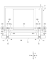
図1は、第1実施形態の作業床1を室外側から視たときの構成図である。図2は、図1のA-A線断面図である。図3は、第1実施形態の作業床1を室内側から視たときの構成図である。各図においては、例えば、ねじ山等の細部の図示を省略する。
図1及び図2に示すように、第1実施形態の作業床1は、作業床用ブラケット2と、床板3と、を備える。作業床用ブラケット2は、窓枠6の室外側Z1に床板3を設置するための構造体である。床板3は、作業者が作業のために載る部材である。作業床用ブラケット2は、戸建ての住宅や集合住宅等の建造物の壁4に設けられた窓(開口部)5の窓枠6に設置される。窓5は、いわゆる引き違い窓として構成されており、窓枠6には、外障子5aと内障子5bが嵌め込まれている。
First Embodiment
Fig. 1 is a configuration diagram of the work floor 1 of the first embodiment as viewed from the outside of the room. Fig. 2 is a cross-sectional view of line A-A in Fig. 1. Fig. 3 is a configuration diagram of the work floor 1 of the first embodiment as viewed from the inside of the room. In each figure, illustration of details such as screw threads is omitted.
As shown in Figures 1 and 2, the work floor 1 of the first embodiment includes a work floor bracket 2 and a floor plate 3. The work floor bracket 2 is a structure for installing the floor plate 3 on the outdoor side Z1 of a window frame 6. The floor plate 3 is a member on which a worker stands for work. The work floor bracket 2 is installed in a window frame 6 of a window (opening) 5 provided in a wall 4 of a building such as a detached house or an apartment building. The window 5 is configured as a so-called sliding window, and an outer screen 5a and an inner screen 5b are fitted into the window frame 6.

作業床用ブラケット2は、第1ブラケット10、第2ブラケット20、第1連結部材16、第2連結部材17等を備える。第1ブラケット10と第2ブラケット20の構成は、正面視において左右対称であり、実質的に同一であるため、第1実施形態では、第1ブラケット10についての説明を、第2ブラケット20の説明として兼用する。そのため、第2ブラケット20を構成する各部の符号は、第1ブラケット10を構成する各部の符号と同じとする。例えば、第1ブラケット10の「本体アーム11」は、第2ブラケット20においても「本体アーム11」と呼称する。 The work floor bracket 2 includes a first bracket 10, a second bracket 20, a first connecting member 16, a second connecting member 17, etc. The configurations of the first bracket 10 and the second bracket 20 are symmetrical when viewed from the front and are substantially identical, so in the first embodiment, the description of the first bracket 10 also serves as the description of the second bracket 20. Therefore, the reference numerals of the parts constituting the second bracket 20 are the same as the reference numerals of the parts constituting the first bracket 10. For example, the "main body arm 11" of the first bracket 10 is also referred to as the "main body arm 11" of the second bracket 20.

図2に示すように、第1ブラケット10は、本体アーム(第1本体アーム/第2本体アーム)11、外アーム(第1外アーム/第2外アーム)12、内アーム(第1内アーム/第2内アーム)14、支持アーム13、外壁当接部(第1外壁当接部、第2外壁当接部)30、内壁当接部(第1内壁当接部/第2内壁当接部)40、窓枠当接部(第1窓枠当接部/第2窓枠当接部)50、外枠部(第1外枠部/第2外枠部)60等を備える。このうち、本体アーム11、外アーム12、支持アーム13、内アーム14、外枠部60等は、例えば、金属製の角パイプにより構成される。各部は、溶接で接合してもよいし、プレートとボルト及びナット等で連結してもよい。また、各部を一体に構成してもよい。例えば、本体アーム11、外アーム12、支持アーム13及び内アーム14を一体に構成してもよい。 As shown in FIG. 2, the first bracket 10 includes a main body arm (first main body arm/second main body arm) 11, an outer arm (first outer arm/second outer arm) 12, an inner arm (first inner arm/second inner arm) 14, a support arm 13, an outer wall abutment portion (first outer wall abutment portion, second outer wall abutment portion) 30, an inner wall abutment portion (first inner wall abutment portion/second inner wall abutment portion) 40, a window frame abutment portion (first window frame abutment portion/second window frame abutment portion) 50, an outer frame portion (first outer frame portion/second outer frame portion) 60, etc. Among these, the main body arm 11, the outer arm 12, the support arm 13, the inner arm 14, the outer frame portion 60, etc. are made of, for example, a metal square pipe. Each part may be joined by welding, or may be connected with a plate, bolts, nuts, etc. Also, each part may be integrally constructed. For example, the main body arm 11, outer arm 12, support arm 13, and inner arm 14 may be integrally configured.

本体アーム11は、窓枠上において室内側Z2から室外側Z1に向けて延在する部材である。窓枠上とは、窓枠6の下側Y2に配置された窓枠部材の上を意味する(図2参照)。図1及び図2に示すように、第1ブラケット10の本体アーム11の窓枠近傍と、第2ブラケット20の本体アーム11の窓枠近傍との間は、第1連結部材16により連結されている。第1連結部材16は、例えば、金属製の角パイプにより構成される。第1連結部材16と本体アーム11は、例えば、プレートとボルト及びナット等で付け外し可能に連結してもよい。なお、「窓枠近傍」とは、本体アーム11が窓枠6と当接する部分の室外側Z1の端から0mm以上500mm以下の範囲で室外側に位置する領域をいう。そのため、第1連結部材16は、第1連結部材16の室内側Z2の端と、本体アーム11が窓枠6と当接する部分の室外側Z1の端との距離が0mm以上500mm以下となるように設置される。 The main body arm 11 is a member that extends from the indoor side Z2 to the outdoor side Z1 on the window frame. On the window frame means above the window frame member arranged on the lower side Y2 of the window frame 6 (see FIG. 2). As shown in FIG. 1 and FIG. 2, the vicinity of the window frame of the main body arm 11 of the first bracket 10 and the vicinity of the window frame of the main body arm 11 of the second bracket 20 are connected by the first connecting member 16. The first connecting member 16 is, for example, made of a metal square pipe. The first connecting member 16 and the main body arm 11 may be connected detachably, for example, by a plate, bolts, nuts, etc. Note that "vicinity of the window frame" refers to an area located on the outdoor side within a range of 0 mm to 500 mm from the end of the outdoor side Z1 of the part where the main body arm 11 abuts the window frame 6. Therefore, the first connecting member 16 is installed so that the distance between the indoor side Z2 end of the first connecting member 16 and the outdoor side Z1 end of the part where the main body arm 11 abuts against the window frame 6 is 0 mm or more and 500 mm or less.

窓枠6に設置される第1ブラケット10と第2ブラケット20との間を第1連結部材16で連結することにより、2つのブラケットの窓枠近傍の部分がそれぞれ幅方向Xの内側に移動したり、外側に移動したりする不具合を抑制できる。なお、第1連結部材16を設ける位置は、図2に示すように、本体アーム11の上側Y1に限らず、例えば、下側Y2であってもよいし、他の位置であってもよい。 By connecting the first bracket 10 and the second bracket 20, which are installed on the window frame 6, with the first connecting member 16, it is possible to prevent the portions of the two brackets near the window frame from moving inward or outward in the width direction X. Note that the position where the first connecting member 16 is provided is not limited to the upper side Y1 of the main body arm 11 as shown in FIG. 2, but may be, for example, the lower side Y2 or another position.

また、第1ブラケット10の本体アーム11の窓枠6よりも室外側Z1の端部と、第2ブラケット20の本体アーム11の窓枠6よりも室外側Z1の端部との間は、第2連結部材17により連結されている。第2連結部材17は、例えば、金属製の角パイプにより構成される。第2連結部材17と本体アーム11は、例えば、プレートとボルト及びナット等で付け外し可能に連結してもよい。なお、第2連結部材17は、各ブラケットにおいて本体アーム11の窓枠よりも室外側Z1の端部に限らず、端部近傍に設けられていてもよい。端部近傍とは、例えば、前記端部から床板領域S(後述)の室外側Z1の端までの領域である。 The end of the main body arm 11 of the first bracket 10 on the outdoor side Z1 from the window frame 6 and the end of the main body arm 11 of the second bracket 20 on the outdoor side Z1 from the window frame 6 are connected by a second connecting member 17. The second connecting member 17 is, for example, made of a metal square pipe. The second connecting member 17 and the main body arm 11 may be connected detachably, for example, with a plate, bolts, nuts, etc. Note that the second connecting member 17 is not limited to the end of the main body arm 11 on the outdoor side Z1 from the window frame of each bracket, but may be provided near the end. The vicinity of the end is, for example, the area from the end to the outdoor side Z1 end of the floor board area S (described later).

窓枠6に設置される第1ブラケット10と第2ブラケット20との間を第2連結部材17で連結することにより、2つのブラケットの室外側Z1の端部が、それぞれ幅方向Xの内側に移動したり、外側に移動したりする不具合をより確実に抑制できる。なお、第2連結部材17を設ける位置は、図2に示す位置に限らず、例えば、本体アーム11の下側Y2で且つ支持アーム13の内側でもよいし、他の位置であってもよい。 By connecting the first bracket 10 and the second bracket 20 installed on the window frame 6 with the second connecting member 17, it is possible to more reliably prevent the ends of the two brackets on the outdoor side Z1 from moving inward or outward in the width direction X. The position at which the second connecting member 17 is provided is not limited to the position shown in FIG. 2, and may be, for example, on the lower side Y2 of the main body arm 11 and inside the support arm 13, or may be in another position.

外アーム12は、本体アーム11の室外側Z1において外壁4aに沿うように設けられる部材であり、外アーム12の長手方向が本体アーム11の長手方向に対して略直交するように本体アーム11に接合されている。外アーム12は、本体アーム11の窓枠近傍から下側Y2に延在する。図2に示すように、本体アーム11において、室外側Z1の端部近傍と外アーム12との間の領域は、床板領域(床板載置予定領域)Sとなる。図1に示すように、第1ブラケット10において、本体アーム11の上側Y1の面には、床板3の右側X1の部分が載せられる。第2ブラケット20において、本体アーム11の上側Y1の面には、床板3の左側X2の部分が載せられる。床板3は、作業床1の左右方向Xにおいて、2つのブラケット間に掛け渡される。なお、作業床1に載置される床板3の数は、1枚に限らず、2枚以上でもよい。 The outer arm 12 is a member provided along the outer wall 4a on the outdoor side Z1 of the main arm 11, and is joined to the main arm 11 so that the longitudinal direction of the outer arm 12 is approximately perpendicular to the longitudinal direction of the main arm 11. The outer arm 12 extends from near the window frame of the main arm 11 to the lower side Y2. As shown in FIG. 2, the area between the end of the main arm 11 on the outdoor side Z1 and the outer arm 12 is the floor board area (area where the floor board is to be placed) S. As shown in FIG. 1, in the first bracket 10, the right side X1 part of the floor board 3 is placed on the upper side Y1 surface of the main arm 11. In the second bracket 20, the left side X2 part of the floor board 3 is placed on the upper side Y1 surface of the main arm 11. The floor board 3 is stretched between the two brackets in the left-right direction X of the work floor 1. The number of floor boards 3 placed on the work floor 1 is not limited to one, and may be two or more.

支持アーム13は、本体アーム11の室外側Z1の端部付近と外アーム12の下側Y2の端部付近とを連結する部材である。
内アーム14は、本体アーム11の室内側Z2において壁4の内壁に沿うように設けられる部材であり、内アーム14の長手方向が本体アーム11の長手方向に対して略直交するように本体アーム11に接合されている。内アームは、本体アーム11の室内側Z2の端部から下側Y2に延在する。図2に示すように、本体アーム11において、外アーム12と内アーム14との間は、窓枠6への設置予定領域となる。なお、本体アーム11において、窓枠6と接する部分に、窓枠6を保護するための緩衝材(例えば、ゴム板)を設けてもよいし、窓枠6との間の高さを調整するための部材(例えば、角材)を設けてもよい。内アーム14の下側Y2の端部には、内壁当接部40のシャフト42(後述)が貫通するシャフト穴14aが奥行方向Zに沿って設けられている。
The support arm 13 is a member that connects the vicinity of the end of the main arm 11 on the outdoor side Z1 to the vicinity of the end of the outer arm 12 on the lower side Y2.
The inner arm 14 is a member provided along the inner wall of the wall 4 on the indoor side Z2 of the main body arm 11, and is joined to the main body arm 11 so that the longitudinal direction of the inner arm 14 is approximately perpendicular to the longitudinal direction of the main body arm 11. The inner arm extends from the end of the indoor side Z2 of the main body arm 11 to the lower side Y2. As shown in FIG. 2, the area between the outer arm 12 and the inner arm 14 in the main body arm 11 is a planned installation area for the window frame 6. In addition, in the main body arm 11, a cushioning material (e.g., a rubber plate) for protecting the window frame 6 may be provided in the part that contacts the window frame 6, or a member (e.g., a square timber) for adjusting the height between the window frame 6 may be provided. At the end of the lower side Y2 of the inner arm 14, a shaft hole 14a through which the shaft 42 (described later) of the inner wall abutment part 40 passes is provided along the depth direction Z.

外壁当接部30は、外アーム12の下側Y2の端部に設けられ、外壁4aと当接する機構である。外壁当接部30は、窓枠6から下側Y2に離間した位置で外壁4aと当接する。外壁当接部30は、ねじ付きパイプ31と、押圧キャップ32と、を備える。ねじ付きパイプ31は、外周面に雄ねじ(不図示)が形成されたパイプ状の部品である。ねじ付きパイプ31の一端側は、外アーム12の下側Y2の端部に取り付けられている。押圧キャップ32は、長手方向に貫通する穴を有し、その穴の内周面にねじ付きパイプ31の雄ねじと螺合可能な雌ねじ(不図示)が形成された略円錐形状の部品である。作業者がねじ付きパイプ31に押圧キャップ32を螺合させて、時計回り又は反時計回りに回すことにより、外アーム12と外壁4aとの間の距離L1を調節することができる。なお、押圧キャップ32の外壁4a側の面にゴムや樹脂製の緩衝材を設けてもよい。また、外壁当接部30の構成は、第1実施形態の例に限らず、同等に機能し得るものであれば、どのような構成としてもよい。第5実施形態(後述)では、外壁当接部30の他の構成例を示している。 The outer wall abutment portion 30 is a mechanism provided at the end of the lower side Y2 of the outer arm 12 and abuts against the outer wall 4a. The outer wall abutment portion 30 abuts against the outer wall 4a at a position spaced from the window frame 6 to the lower side Y2. The outer wall abutment portion 30 includes a threaded pipe 31 and a pressing cap 32. The threaded pipe 31 is a pipe-shaped part having a male thread (not shown) formed on the outer peripheral surface. One end side of the threaded pipe 31 is attached to the end of the lower side Y2 of the outer arm 12. The pressing cap 32 is a substantially conical part having a hole penetrating in the longitudinal direction and a female thread (not shown) formed on the inner peripheral surface of the hole that can be screwed with the male thread of the threaded pipe 31. The worker can adjust the distance L1 between the outer arm 12 and the outer wall 4a by screwing the pressing cap 32 onto the threaded pipe 31 and turning it clockwise or counterclockwise. In addition, a cushioning material made of rubber or resin may be provided on the surface of the pressing cap 32 facing the outer wall 4a. In addition, the configuration of the outer wall contact portion 30 is not limited to the example of the first embodiment, and any configuration that can function equally well may be used. In the fifth embodiment (described later), another configuration example of the outer wall contact portion 30 is shown.

内壁当接部40は、内アーム14の下側Y2の端部に設けられ、内壁4bと当接する機構である。内壁当接部40は、窓枠6から下側Y2に離間した位置で内壁4bに当接する。内壁当接部40は、押え部41、シャフト42、ナット43、ダイヤル44、押圧部材15を備える。押え部41は、図2に示すように、押圧部材15を保持する略凹形状の部品である。押圧部材15は、内壁当接部40(押え部41)により内壁4bに当接して、内壁4bを押圧する部材である。押圧部材15としては、内壁4bの表面に損傷等を与えにくい材料であることが好ましく、例えば、木材、樹脂材等を用いることができる。図3に示すように、押圧部材15は、作業床用ブラケット2の幅方向Xに沿って延在しているため、内壁4bを、より広い面積で押圧できる。なお、押圧部材15は、後述する第4実施形態のように、左右の内壁当接部40において、それぞれ単体で設けられていてもよい。 The inner wall abutment portion 40 is a mechanism provided at the end of the lower side Y2 of the inner arm 14 and abuts against the inner wall 4b. The inner wall abutment portion 40 abuts against the inner wall 4b at a position spaced from the window frame 6 to the lower side Y2. The inner wall abutment portion 40 includes a pressing portion 41, a shaft 42, a nut 43, a dial 44, and a pressing member 15. As shown in FIG. 2, the pressing portion 41 is a generally concave-shaped part that holds the pressing member 15. The pressing member 15 is a member that abuts against the inner wall 4b by the inner wall abutment portion 40 (pressing portion 41) and presses the inner wall 4b. The pressing member 15 is preferably made of a material that is unlikely to cause damage to the surface of the inner wall 4b, and for example, wood, resin, etc. can be used. As shown in FIG. 3, the pressing member 15 extends along the width direction X of the work floor bracket 2, so that the inner wall 4b can be pressed over a wider area. Note that the pressing member 15 may be provided separately on each of the left and right inner wall contact portions 40, as in the fourth embodiment described below.

シャフト42は、棒状の部品であり、一方の端部が押え部41に連結されている。また、シャフト42の他方の端部には、ダイヤル44(後述)が取り付けられている。シャフト42の外周面には、ナット43(後述)と螺合可能な雄ねじが形成されている。シャフト42は、内アーム14の下側Y2の端部に設けられたシャフト穴14aを貫通している。 The shaft 42 is a rod-shaped part, one end of which is connected to the pressing part 41. A dial 44 (described later) is attached to the other end of the shaft 42. A male thread is formed on the outer circumferential surface of the shaft 42, which can be screwed into a nut 43 (described later). The shaft 42 passes through a shaft hole 14a provided at the end of the lower side Y2 of the inner arm 14.

ナット43は、内周面にシャフト42と螺合可能な雌ねじが形成された部品である。ナット43は、内アーム14の下側Y2の端部において、後側Z2に設けられている。ナット43は、内アーム14に、例えば、溶接により接合してもよい。ナット43の中心は、シャフト穴14aの中心と一致している。ダイヤル44は、内壁4bと内アーム14との間の長さ(間隔)L2を調節するために、作業者が操作する部品である。ダイヤル44は、シャフト42の他方の端部に取り付けられている。ダイヤル44を時計回り又は反時計回りに回動させることにより、内壁4bと内アーム14との間の長さ(間隔)L2を調節することができる。なお、内壁当接部40の構成は、第1実施形態の例に限らず、同等に機能し得るものであれば、どのような構成としてもよい。例えば、奥行方向Zに所定の長さを有する角材であってもよい。 The nut 43 is a part having a female thread formed on the inner circumferential surface thereof, which can be screwed with the shaft 42. The nut 43 is provided on the rear side Z2 at the end of the lower side Y2 of the inner arm 14. The nut 43 may be joined to the inner arm 14, for example, by welding. The center of the nut 43 coincides with the center of the shaft hole 14a. The dial 44 is a part operated by an operator to adjust the length (spacing) L2 between the inner wall 4b and the inner arm 14. The dial 44 is attached to the other end of the shaft 42. The length (spacing) L2 between the inner wall 4b and the inner arm 14 can be adjusted by rotating the dial 44 clockwise or counterclockwise. The configuration of the inner wall abutment portion 40 is not limited to the example of the first embodiment, and any configuration may be used as long as it functions in the same way. For example, it may be a square timber having a predetermined length in the depth direction Z.

窓枠当接部50は、第1ブラケット10を室内側Z2から支持する構造体であり、本体アーム11の室内側Z2に設けられている。窓枠当接部50は、支柱板51と、当接板52と、を備える。支柱板51は、図2及び図3に示すように、本体アーム11の室内側Z2の端部に設けられ、上側Y1に向けて延在する部材である。支柱板51の上側Y1の端部には、当接板52の一方の端部が固定されている。当接板52は、支柱板51の上側Y1の端部に設けられ、窓枠6と当接する部材である。 The window frame abutment portion 50 is a structure that supports the first bracket 10 from the indoor side Z2, and is provided on the indoor side Z2 of the main body arm 11. The window frame abutment portion 50 includes a support plate 51 and an abutment plate 52. As shown in Figures 2 and 3, the support plate 51 is a member that is provided at the end of the indoor side Z2 of the main body arm 11 and extends toward the upper side Y1. One end of the abutment plate 52 is fixed to the end of the upper side Y1 of the support plate 51. The abutment plate 52 is a member that is provided at the end of the upper side Y1 of the support plate 51 and abuts against the window frame 6.

図3に示すように、第1ブラケット10の窓枠当接部50において、当接板52は、一方の端部が支柱板51に固定されている。他方の端部は、支柱板51から右側(図3では左方向)X1に突出して窓枠6と当接する。第2ブラケット20の窓枠当接部50において、当接板52は、一方の端部が支柱板51に固定されている。他方の端部は、支柱板51から左側(図3では右方向)X2に突出して窓枠6と当接する。上記構成によれば、外障子5aと内障子5bとを取り外した窓5から、作業者が室外側から室内側へ移動したり、室内側から室外側へ移動したりすることを容易に行うことができる。なお、第1実施形態では、左右の当接板52が窓枠6と当接する例を示すが、当接板52は、窓枠6の開口部(窓)周辺の内壁4bと当接するように構成してもよし、窓枠6と窓枠6の開口部(窓)周辺の内壁4bとの両方と当接するように構成してもよい。 As shown in FIG. 3, at the window frame abutment portion 50 of the first bracket 10, the abutment plate 52 has one end fixed to the support plate 51. The other end protrudes from the support plate 51 to the right (left direction in FIG. 3) X1 to abut against the window frame 6. At the window frame abutment portion 50 of the second bracket 20, the abutment plate 52 has one end fixed to the support plate 51. The other end protrudes from the support plate 51 to the left (right direction in FIG. 3) X2 to abut against the window frame 6. With the above configuration, a worker can easily move from the outside to the inside of the room and from the inside to the outside of the room from the window 5 with the outer screen 5a and inner screen 5b removed. In the first embodiment, an example is shown in which the left and right abutment plates 52 abut against the window frame 6, but the abutment plates 52 may be configured to abut against the inner wall 4b around the opening (window) of the window frame 6, or may be configured to abut against both the window frame 6 and the inner wall 4b around the opening (window) of the window frame 6.

外枠部60は、床板領域Sに載置された床板3の跳ね上がりを抑制するための部材である。図2に示すように、外枠部60は、本体アーム11の上側Y1において、床板領域Sに載置された床板3を囲むように設けられている。なお、床板3は、本体アーム11の床板領域Sにおいて、ボルト等により固定することが望ましいが、本体アーム11の上側Y1の面に載置するだけでも使用できる。その場合、作業者が床板3上を移動したり、バランスを崩したりしても、外枠部60により、床板3の跳ね上がりによる作業者の転落を可及的に回避できる。 The outer frame portion 60 is a member for preventing the floor board 3 placed on the floor board area S from bouncing up. As shown in FIG. 2, the outer frame portion 60 is provided on the upper side Y1 of the main body arm 11 so as to surround the floor board 3 placed on the floor board area S. It is preferable to fix the floor board 3 to the floor board area S of the main body arm 11 with bolts or the like, but it can also be used by simply placing it on the surface of the upper side Y1 of the main body arm 11. In that case, even if a worker moves on the floor board 3 or loses balance, the outer frame portion 60 can prevent the worker from falling due to the floor board 3 bouncing up as much as possible.

上記のように構成された第1実施形態の作業床1は、例えば、以下のようにして窓枠6に設置できる。
まず、図1に示すように、窓枠6に嵌め込まれた外障子5a(内障子5b)を移動して、窓枠6の左右方向Xの両側に空間を確保する。次に、第1ブラケット10及び第2ブラケット20を、室内側から窓枠6の右側X1と左側X2にそれぞれ設置する。具体的には、図2に示すように、本体アーム11の外アーム12と内アーム14との間(窓枠への設置予定領域)を窓枠6の上に掛け渡すように設置する。なお、各ブラケットを設置する際、外アーム12と外壁4aとの間の距離L1を、適切な寸法に調節しておくことが望ましい。
The work platform 1 of the first embodiment configured as described above can be installed on the window frame 6, for example, as follows.
First, as shown in Figure 1, the outer screen 5a (inner screen 5b) fitted into the window frame 6 is moved to ensure space on both sides of the window frame 6 in the left-right direction X. Next, the first bracket 10 and the second bracket 20 are installed on the right side X1 and left side X2 of the window frame 6 from the inside of the room, respectively. Specifically, as shown in Figure 2, they are installed so that they span the area between the outer arm 12 and the inner arm 14 of the main body arm 11 (the area to be installed in the window frame) over the window frame 6. When installing each bracket, it is desirable to adjust the distance L1 between the outer arm 12 and the exterior wall 4a to an appropriate dimension.

次に、図2に示すように、2つのブラケットの間に第1連結部材16及び第2連結部材17を取り付ける。第1連結部材16及び第2連結部材17は、2つのブラケットの間に予め取り付けてもよい。
次に、図3に示すように、各ブラケットの内壁当接部40(押え部41)に押圧部材15を通し、窓枠当接部50の当接板52が窓枠6に当接するように、内壁4bと内アーム14との間の距離L2を調節する。内壁4bと内アーム14との間の距離L2は、ダイヤル44を時計回り又は反時計回りに回すことにより調節できる。窓枠当接部50の当接板52が窓枠6に当接するように内壁当接部40を調節した後、外壁当接部30の押圧キャップ32を時計回り又は反時計回りに回転させて、外壁当接部30(押圧キャップ32)により外壁4aが押圧されるように、外アーム12と外壁4aとの間の距離L1を調節する。なお、この際に、本体アーム11が水平でない場合には、本体アーム11が水平となるように調節する。
Next, the first connecting member 16 and the second connecting member 17 are attached between the two brackets as shown in Fig. 2. The first connecting member 16 and the second connecting member 17 may be attached between the two brackets in advance.
Next, as shown in FIG. 3, the pressing member 15 is passed through the inner wall abutment portion 40 (pressing portion 41) of each bracket, and the distance L2 between the inner wall 4b and the inner arm 14 is adjusted so that the abutment plate 52 of the window frame abutment portion 50 abuts against the window frame 6. The distance L2 between the inner wall 4b and the inner arm 14 can be adjusted by turning the dial 44 clockwise or counterclockwise. After adjusting the inner wall abutment portion 40 so that the abutment plate 52 of the window frame abutment portion 50 abuts against the window frame 6, the pressing cap 32 of the outer wall abutment portion 30 is rotated clockwise or counterclockwise to adjust the distance L1 between the outer arm 12 and the outer wall 4a so that the outer wall abutment portion 30 (pressing cap 32) presses the outer wall 4a. At this time, if the main body arm 11 is not horizontal, the main body arm 11 is adjusted so that it is horizontal.

上記作業により、各ブラケットの左右方向X及び奥行方向Zへの移動を規制することができる。この後、本体アーム11の床板領域Sに床板3を載置し、本体アーム11にボルト等により固定することにより、作業床1の設置が完了する。なお、窓枠6に作業床1を設置する手順は、上記の例に限らず、例えば、窓枠6の形状や作業者の人数等に応じて適宜に変更してよい。 The above work restricts the movement of each bracket in the left-right direction X and the depth direction Z. After this, the floor board 3 is placed on the floor board area S of the main body arm 11 and fixed to the main body arm 11 with bolts or the like, completing the installation of the work floor 1. Note that the procedure for installing the work floor 1 on the window frame 6 is not limited to the above example, and may be changed as appropriate depending on, for example, the shape of the window frame 6 and the number of workers.

上述した第1実施形態の作業床1及び作業床用ブラケット2によれば、例えば、以下のような効果を奏する。
作業床1及び作業床用ブラケット2は、床板3に載った作業者の荷重を、外壁当接部30と窓枠当接部50により受け止めることができる。このうち、窓枠当接部50は、窓枠6が内壁4bから突出した部分の下側Y2に係止されないため、窓枠6が内壁4bから突出する部分が、荷重を受け止めるのに十分な長さでない場合や、窓枠6が内壁4bから突出しない場合においても、作業者の荷重をより確実に受け止めることができる。したがって、第1実施形態の作業床1及び作業床用ブラケット2は、窓枠6に、より安定して設置できる。また、左右のブラケットにおいて、窓枠当接部50の当接板52は、左右方向Xにおいて繋がっていない。そのため、作業者は、窓枠当接部50と干渉することなしに、室内側Z2から作業床1に出たり、作業床1から室内側Z2に入ったりできる。
According to the work platform 1 and the work platform bracket 2 of the first embodiment described above, for example, the following effects are achieved.
The work floor 1 and the work floor bracket 2 can receive the load of a worker standing on the floor board 3 by the exterior wall abutment portion 30 and the window frame abutment portion 50. Among these, the window frame abutment portion 50 is not engaged with the lower side Y2 of the portion where the window frame 6 protrudes from the inner wall 4b, so that the load of the worker can be more reliably received even when the portion where the window frame 6 protrudes from the inner wall 4b is not long enough to receive the load or when the window frame 6 does not protrude from the inner wall 4b. Therefore, the work floor 1 and the work floor bracket 2 of the first embodiment can be more stably installed on the window frame 6. In addition, in the left and right brackets, the abutment plates 52 of the window frame abutment portion 50 are not connected in the left-right direction X. Therefore, the worker can enter the work floor 1 from the indoor side Z2 and enter the indoor side Z2 from the work floor 1 without interfering with the window frame abutment portion 50.

作業床1及び作業床用ブラケット2は、内アーム14において、窓枠6から下側Y2に離間した位置で内壁4bに当接する内壁当接部40を備える。作業床1及び作業床用ブラケット2は、内壁当接部40と外壁当接部30とにより、壁4を奥行方向Zで挟み込むように押圧できるため、各ブラケットの奥行方向Zへの移動をより確実に規制できる。また、内壁当接部40を設けることにより、窓枠当接部50で受ける荷重の一部を分散させることができる。 The work floor 1 and the work floor bracket 2 are provided with an inner wall abutment portion 40 on the inner arm 14 that abuts against the inner wall 4b at a position spaced from the window frame 6 to the lower side Y2. The work floor 1 and the work floor bracket 2 can press the wall 4 in the depth direction Z by the inner wall abutment portion 40 and the outer wall abutment portion 30, so that the movement of each bracket in the depth direction Z can be more reliably restricted. In addition, by providing the inner wall abutment portion 40, a part of the load received by the window frame abutment portion 50 can be dispersed.

作業床1及び作業床用ブラケット2は、第1ブラケット10の本体アーム11の窓枠近傍と、第2ブラケット20の本体アーム11の窓枠近傍との間を連結する第1連結部材16を備える。そのため、作業床1及び作業床用ブラケット2において、2つのブラケットの窓枠近傍の部分がそれぞれ幅方向Xの内側に移動したり、外側に移動したりする不具合を抑制できる。 The work floor 1 and the work floor bracket 2 are provided with a first connecting member 16 that connects between the window frame vicinity of the main arm 11 of the first bracket 10 and the window frame vicinity of the main arm 11 of the second bracket 20. Therefore, in the work floor 1 and the work floor bracket 2, it is possible to suppress the malfunction in which the portions of the two brackets near the window frames move inward or outward in the width direction X.

作業床1及び作業床用ブラケット2は、第1ブラケット10の本体アーム11の窓枠6よりも室外側Z1の端部と、第2ブラケット20の本体アーム11の窓枠6よりも室外側Z1の端部との間を連結する第2連結部材17を備える。そのため、作業床1及び作業床用ブラケット2において、2つのブラケットの室外側Z1の端部が、それぞれ左右方向Xの内側に移動したり、外側に移動したりする不具合をより確実に抑制できる。 The work floor 1 and the work floor bracket 2 are provided with a second connecting member 17 that connects the end of the main arm 11 of the first bracket 10 on the outdoor side Z1 relative to the window frame 6 to the end of the main arm 11 of the second bracket 20 on the outdoor side Z1 relative to the window frame 6. Therefore, in the work floor 1 and the work floor bracket 2, the outdoor side Z1 ends of the two brackets can be more reliably prevented from moving inward or outward in the left-right direction X.

作業床1及び作業床用ブラケット2は、本体アーム11の床板領域Sを囲むように設けられる外枠部60を備える。そのため、本体アーム11の床板領域Sに床板3を固定せずに載置した場合に、作業者が床板3上を移動したり、重さのバランスが崩れたりしても、外枠部60により、床板3の跳ね上がりによる作業者の転落を可及的に回避できる。 The work floor 1 and the work floor bracket 2 are provided with an outer frame portion 60 that is provided to surround the floor board area S of the main body arm 11. Therefore, when the floor board 3 is placed on the floor board area S of the main body arm 11 without being fixed, even if the worker moves on the floor board 3 or the weight balance is lost, the outer frame portion 60 can prevent the worker from falling due to the floor board 3 bouncing up as much as possible.

(第2実施形態)
第2実施形態の作業床1Aは、防護柵(柵部)70を備える点が第1実施形態と相違する。第2実施形態の作業床1Aにおいて、その他の構成は、第1実施形態と同じである。そのため、第2実施形態の説明及び図面において、第1実施形態と同一の部材及び同等の部材には、第1実施形態と同一の符号を付し、重複する説明を省略する。
Second Embodiment
The working floor 1A of the second embodiment differs from the first embodiment in that it is provided with a protective fence (fence portion) 70. The other configurations of the working floor 1A of the second embodiment are the same as those of the first embodiment. Therefore, in the explanation and drawings of the second embodiment, the same members and equivalent members as those of the first embodiment are given the same reference numerals as those of the first embodiment, and duplicate explanations will be omitted.

図4は、第2実施形態の作業床1Aを室外側から視たときの構成図である。図5及び図6は、図4のB-B線に相当する断面図である。図5は、防護柵70を直立させた使用状態を示している。図6は、防護柵70を折り畳んだ収納状態を示している。なお、図5及び図6では、窓5の上側Y1の構成及び本体アーム11よりも下側Y2の構成を一部省略している。 Figure 4 is a diagram of the work platform 1A of the second embodiment as viewed from the outside of the room. Figures 5 and 6 are cross-sectional views corresponding to line B-B in Figure 4. Figure 5 shows the protective fence 70 in an upright position when in use. Figure 6 shows the protective fence 70 in a folded, stored position. Note that Figures 5 and 6 omit some of the configuration above the window 5 on the Y1 side and the configuration below the main body arm 11 on the Y2 side.

図4及び図5に示すように、第2実施形態の作業床1Aは、第1ブラケット10と第2ブラケット20の上側(Y1)に防護柵70を備える。防護柵70は、床板3に載っている作業者の転落を抑制するための構造体である。防護柵70は、第1支柱部材71、第2支柱部材72、第3連結部材73、第1可動部74、第2可動部75等により構成される。図4に示すように、第1支柱部材71は、第1ブラケット10において、本体アーム11の室外側Z1の端部に設けられ、前記端部から上側Y1に延在する部材である。第2支柱部材72は、第2ブラケット20において、本体アーム11の室外側Z1の端部に設けられ、前記端部から上側Y1に延在する部材である。第3連結部材73は、第1支柱部材71の上側Y1の端部と、第2支柱部材72の上側Y1の端部との間を連結する部材である。第1支柱部材71、第2支柱部材72及び第3連結部材73は、例えば、金属製の角パイプにより構成される。図4に示すように、防護柵70は、第1支柱部材71、第2支柱部材72及び第3連結部材73により、逆凹形状に構成されている。 4 and 5, the work floor 1A of the second embodiment is provided with a guard fence 70 on the upper side (Y1) of the first bracket 10 and the second bracket 20. The guard fence 70 is a structure for preventing a worker standing on the floor plate 3 from falling. The guard fence 70 is composed of a first support member 71, a second support member 72, a third connecting member 73, a first movable part 74, a second movable part 75, etc. As shown in FIG. 4, the first support member 71 is a member provided at the end of the outside Z1 of the main body arm 11 in the first bracket 10 and extending from the end to the upper side Y1. The second support member 72 is a member provided at the end of the outside Z1 of the main body arm 11 in the second bracket 20 and extending from the end to the upper side Y1. The third connecting member 73 is a member that connects the upper Y1 end of the first support member 71 and the upper Y1 end of the second support member 72. The first support member 71, the second support member 72, and the third connecting member 73 are made of, for example, metal square pipes. As shown in FIG. 4, the protective fence 70 is made into an inverted concave shape by the first support member 71, the second support member 72, and the third connecting member 73.

第1支柱部材71は、第1可動部74を介して外枠部60に連結されている。第1可動部74は、第1支柱部材71を第1ブラケット10の本体アーム11に対して回動自在に支持する機構である。第2可動部75は、第2支柱部材72を第2ブラケット20の本体アーム11に対して回動自在に支持する機構である。第1可動部74及び第2可動部75の構成は実質的に同一であるため、第2実施形態では、第1可動部74についての説明を、第2可動部75の説明として兼用する。 The first support member 71 is connected to the outer frame portion 60 via the first movable portion 74. The first movable portion 74 is a mechanism that supports the first support member 71 rotatably relative to the main body arm 11 of the first bracket 10. The second movable portion 75 is a mechanism that supports the second support member 72 rotatably relative to the main body arm 11 of the second bracket 20. Since the configurations of the first movable portion 74 and the second movable portion 75 are substantially the same, in the second embodiment, the description of the first movable portion 74 also serves as the description of the second movable portion 75.

第1可動部74は、支持プレート76、回動軸部77及び固定軸部78を備える。支持プレート76は、第1支柱部材71の下側Y2を支持する部材である。支持プレート76は、上下方向Yから視たときに、第1支柱部材71の室外側Z1、右側X1及び左側X2の3方を囲むように略凹形状に構成されている。また、図5に示すように、支持プレート76は、左右方向Xから視たときに、略L字形に構成されている。第1支柱部材71の下側Y2の端部は、防護柵70を直立させた状態において、外枠部60の上側Y1と当接するように支持プレート76に支持されている。また、支持プレート76には、回動軸部77及び固定軸部78(後述)が貫通する貫通穴が設けられている。図4及び図5では、固定軸部78が貫通する貫通穴の図示を省略する。固定軸部78が貫通する貫通穴76aを図6に示す。 The first movable part 74 includes a support plate 76, a rotating shaft part 77, and a fixed shaft part 78. The support plate 76 is a member that supports the lower side Y2 of the first support member 71. When viewed from the vertical direction Y, the support plate 76 is configured to have a substantially concave shape so as to surround the three sides of the first support member 71, namely, the outdoor side Z1, the right side X1, and the left side X2. Also, as shown in FIG. 5, the support plate 76 is configured to have a substantially L-shape when viewed from the horizontal direction X. The end of the lower side Y2 of the first support member 71 is supported by the support plate 76 so as to abut against the upper side Y1 of the outer frame part 60 when the protective fence 70 is in an upright state. Also, the support plate 76 is provided with a through hole through which the rotating shaft part 77 and the fixed shaft part 78 (described later) pass. In FIG. 4 and FIG. 5, the through hole through which the fixed shaft part 78 passes is omitted. FIG. 6 shows the through hole 76a through which the fixed shaft part 78 passes.

回動軸部77は、支持プレート76を外枠部60に対して回動自在に支持する部品である。回動軸部77は、例えば、ボルトとナット(符号を省略)により構成される。第2実施形態の外枠部60には、回動軸部77(ボルト)を貫通させる貫通穴(不図示)が設けられている。外枠部60において、後述する固定軸部78(ボルト)が貫通する貫通穴60aを図6に示す。回動軸部77は、通常の使用状態においては、固定軸部78(後述)のように着脱されることはない。 The pivot shaft 77 is a component that supports the support plate 76 so that it can rotate freely relative to the outer frame 60. The pivot shaft 77 is formed, for example, of a bolt and nut (reference numbers omitted). The outer frame 60 of the second embodiment is provided with a through hole (not shown) through which the pivot shaft 77 (bolt) passes. Figure 6 shows a through hole 60a in the outer frame 60 through which a fixed shaft 78 (bolt) described later passes. Under normal use, the pivot shaft 77 is not attached or detached like the fixed shaft 78 (described later).

固定軸部78は、支持プレート76を外枠部60に固定したり、固定を解除したりするための機構である。固定軸部78は、例えば、ボルトとナット(符号を省略)により構成される。図5に示すように、防護柵70(第1支柱部材71、第2支柱部材72)を直立させた状態で、支持プレート76に固定軸部78を取り付けることにより、防護柵70を使用状態にできる。また、図5において、支持プレート76から固定軸部78を取り外し、防護柵70を矢印方向に倒すと、防護柵70は、回動軸部77を中心として時計回りに回動する。これにより、図6に示すように、防護柵70を外枠部60と重なり合うように折り畳むことができる。 The fixed shaft portion 78 is a mechanism for fixing and releasing the support plate 76 to the outer frame portion 60. The fixed shaft portion 78 is, for example, composed of a bolt and a nut (reference numerals omitted). As shown in FIG. 5, the protective fence 70 (first support member 71, second support member 72) can be placed in an upright position by attaching the fixed shaft portion 78 to the support plate 76, thereby putting the protective fence 70 into a usable state. Also, in FIG. 5, when the fixed shaft portion 78 is removed from the support plate 76 and the protective fence 70 is tilted in the direction of the arrow, the protective fence 70 rotates clockwise around the pivot shaft portion 77. This allows the protective fence 70 to be folded so that it overlaps with the outer frame portion 60, as shown in FIG. 6.

第2実施形態の作業床1A及び作業床用ブラケット2は、防護柵70を備えるため、作業者の室外側Z1への転落を可及的に回避できる。また、防護柵70は、第1可動部74及び第2可動部75において、折り畳みができるため、作業床1A及び作業床用ブラケット2の搬送が容易となる。また、作業床1A及び作業床用ブラケット2の保管スペースをより小さくできる。なお、第2実施形態の構成は、後述する第3実施形態や第4実施形態にも適用できる。 The work floor 1A and the work floor bracket 2 of the second embodiment are equipped with a protective fence 70, which can prevent workers from falling to the outside Z1 as much as possible. In addition, the protective fence 70 can be folded at the first movable part 74 and the second movable part 75, which makes it easy to transport the work floor 1A and the work floor bracket 2. In addition, the storage space for the work floor 1A and the work floor bracket 2 can be made smaller. The configuration of the second embodiment can also be applied to the third and fourth embodiments described below.

(第3実施形態)
第3実施形態の作業床1Bは、窓枠当接部150の構成が第1実施形態と相違する。第3実施形態の作業床1Bにおいて、その他の構成は、第1実施形態と同じである。そのため、第3実施形態の説明及び図面において、第1実施形態と同一の部材及び同等の部材には、第1実施形態と同一の符号又は末尾(下2桁)に同一の符号を付し、重複する説明を省略する。第3実施形態の作業床1Bにおいて、室外側Z1の構成は、第1実施形態と同じであるため、主に室内側Z2の構成について説明する。
Third Embodiment
The working floor 1B of the third embodiment differs from the first embodiment in the configuration of the window frame abutment portion 150. The other configurations of the working floor 1B of the third embodiment are the same as those of the first embodiment. Therefore, in the explanation and drawings of the third embodiment, the same reference numerals as those of the first embodiment or the same reference numerals at the end (the last two digits) of the reference numerals are used for the same members and equivalent members as those of the first embodiment, and duplicate explanations are omitted. In the working floor 1B of the third embodiment, the configuration of the outdoor side Z1 is the same as that of the first embodiment, so the configuration of the indoor side Z2 will mainly be described.

図7は、第3実施形態の作業床1Bを室内側から視たときの構成図である。図7に示すように、第3実施形態の窓枠当接部150は、支柱板151、当接板152及び外周当接板153を備える。支柱板151と当接板152は、第1実施形態の支柱板51と当接板52と同じである。外周当接板153は、窓枠6の開口部(窓)周辺の内壁4bと当接する部材である。第3実施形態の窓枠当接部150は、当接板152が窓枠6と当接し、外周当接板153が窓枠6の開口部周辺の内壁4bと当接する。外周当接板153は、1つの部材で構成されてもよいし、複数の部材を接合した構成としてもよい。なお、外周当接板153の一部は、窓枠6と当接してもよい。 Figure 7 is a diagram of the working floor 1B of the third embodiment as viewed from the inside of the room. As shown in Figure 7, the window frame abutment portion 150 of the third embodiment includes a support plate 151, an abutment plate 152, and an outer periphery abutment plate 153. The support plate 151 and the abutment plate 152 are the same as the support plate 51 and the abutment plate 52 of the first embodiment. The outer periphery abutment plate 153 is a member that abuts against the inner wall 4b around the opening (window) of the window frame 6. In the window frame abutment portion 150 of the third embodiment, the abutment plate 152 abuts against the window frame 6, and the outer periphery abutment plate 153 abuts against the inner wall 4b around the opening of the window frame 6. The outer periphery abutment plate 153 may be composed of one member, or may be composed of multiple members joined together. Note that a part of the outer periphery abutment plate 153 may abut against the window frame 6.

窓枠6の外周部分には、補強材(例えば、垂木等)が内装されている。第3実施形態の作業床1B及び作業床用ブラケット2は、外周当接板153を、この補強材の位置で支持できるため、作業床1B及び作業床用ブラケット2を、窓枠6により安定して設置できる。なお、第3実施形態の構成は、前述した第2実施形態や後述する第4実施形態(同じ部屋の場合)にも適用できる。 Reinforcing materials (e.g., rafters, etc.) are installed on the outer periphery of the window frame 6. The work floor 1B and work floor bracket 2 of the third embodiment can support the outer periphery abutment plate 153 at the position of this reinforcing material, so the work floor 1B and work floor bracket 2 can be installed more stably on the window frame 6. The configuration of the third embodiment can also be applied to the second embodiment described above and the fourth embodiment described below (in the case of the same room).

(第4実施形態)
第4実施形態の作業床1Cは、窓枠当接部50の一部の構成が第1実施形態と相違する。第4実施形態の作業床1Cにおいて、その他の構成は、第1実施形態と同じである。すなわち、第4実施形態の作業床1Cは、窓枠当接部50の一部の構成を除いて、第1実施形態に示す作業床1と同じ構成を備えている。そのため、第4実施形態の説明及び図面において、第1実施形態と同一の部材及び同等の部材には、第1実施形態と同一の符号を付し、重複する説明を省略する。
Fourth Embodiment
The working floor 1C of the fourth embodiment differs from the first embodiment in the configuration of a portion of the window frame abutment portion 50. The other configurations of the working floor 1C of the fourth embodiment are the same as those of the first embodiment. That is, the working floor 1C of the fourth embodiment has the same configuration as the working floor 1 shown in the first embodiment, except for the configuration of a portion of the window frame abutment portion 50. Therefore, in the explanation and drawings of the fourth embodiment, the same members and equivalent members as those of the first embodiment are given the same reference numerals as those of the first embodiment, and duplicate explanations will be omitted.

図8は、第4実施形態の作業床1Cを室外側から視たときの構成図である。図9は、第4実施形態の作業床1Cを室内側から視たときの構成図である。図8に示すように、第4実施形態の作業床1Cは、隣接する窓(第1開口部)5Aと窓(第2開口部)5Bの間に設置される。室内側において、2つの窓5A、5Bの間は、つながっていてもよいし、壁により仕切られていてもよい。すなわち、窓5Aと5Bは、同じ部屋に設けられた窓であってもよいし、隣接する別の部屋の窓であってもよい。 Figure 8 is a diagram of the working floor 1C of the fourth embodiment as viewed from the outside of the room. Figure 9 is a diagram of the working floor 1C of the fourth embodiment as viewed from the inside of the room. As shown in Figure 8, the working floor 1C of the fourth embodiment is installed between adjacent windows (first opening) 5A and (second opening) 5B. On the inside of the room, the two windows 5A and 5B may be connected, or may be separated by a wall. That is, the windows 5A and 5B may be windows installed in the same room, or may be windows in different adjacent rooms.

図8及び図9に示すように、第4実施形態の作業床1Cは、第1ブラケット10及び第2ブラケット20において、それぞれの窓枠当接部50の当接板52の向きが第1実施形態と相違する。図8及び図9に示すように、第1ブラケット10の窓枠当接部50において、当接板52は、支柱板51から左側(図9では右方向)X2に突出して窓枠(第1窓枠)6Aと当接する。第2ブラケット20の窓枠当接部50において、当接板52は、支柱板51から右側(図9では左方向)X1に突出して窓枠(第2窓枠)6Bと当接する。また、図9に示すように、第4実施形態の作業床1Cにおいて、押圧部材15は、それぞれのブラケットの位置に単体で設けられている。 8 and 9, the working floor 1C of the fourth embodiment differs from the first embodiment in the orientation of the abutment plate 52 of each window frame abutment portion 50 of the first bracket 10 and the second bracket 20. As shown in FIG. 8 and FIG. 9, in the window frame abutment portion 50 of the first bracket 10, the abutment plate 52 protrudes from the support plate 51 to the left side (right direction in FIG. 9) X2 and abuts against the window frame (first window frame) 6A. In the window frame abutment portion 50 of the second bracket 20, the abutment plate 52 protrudes from the support plate 51 to the right side (left direction in FIG. 9) X1 and abuts against the window frame (second window frame) 6B. Also, as shown in FIG. 9, in the working floor 1C of the fourth embodiment, the pressing member 15 is provided separately at the position of each bracket.

第4実施形態によれば、作業床1C及び作業床用ブラケット2を、隣接する2つの窓の間に設置できるため、窓にシャッタを取り付けたり、窓枠周辺の外壁にエアコンのダクトを通す穴を開けたりする作業だけでなく、例えば、隣接する2つの窓の間で外壁の工事等を行う場合においても、作業のための床板を安定して設置できる。 According to the fourth embodiment, the work floor 1C and the work floor bracket 2 can be installed between two adjacent windows, so that the floor boards for work can be stably installed not only when attaching shutters to windows or drilling holes in the exterior wall around the window frame to pass air conditioner ducts through, but also when, for example, carrying out construction work on the exterior wall between two adjacent windows.

なお、第4実施形態において、第1ブラケット10の当接板52の向きと、第2ブラケット20の当接板52の向きは、図8の例に限定されない。第1ブラケット10と第2ブラケット20を幅方向(X方向)に更に離間させた形態において、第1ブラケット10の当接板52を、支柱板51から右側(図9では左方向)X1に突出させ、窓枠6Aの右端(不図示)と当接させると共に、第2ブラケット20の当接板52を、支柱板51から左側(図9では右方向)X2に突出させ、窓枠6Bの左端(不図示)と当接させてもよい。また、図8に示す構成において、第1ブラケット10の当接板52のみを、支柱板51から右側(図9では左方向)X1突出させ、窓枠6Aの右端(不図示)と当接させてもよい。更に、図8に示す構成において、第2ブラケット20の当接板52のみを、支柱板51から左側(図9では右方向)X2に突出させ、窓枠6Bの左端(不図示)と当接させてもよい。 In the fourth embodiment, the orientation of the abutment plate 52 of the first bracket 10 and the orientation of the abutment plate 52 of the second bracket 20 are not limited to the example in FIG. 8. In a configuration in which the first bracket 10 and the second bracket 20 are further separated in the width direction (X direction), the abutment plate 52 of the first bracket 10 may be protruded from the support plate 51 to the right side (left direction in FIG. 9) X1 and abutted against the right end (not shown) of the window frame 6A, and the abutment plate 52 of the second bracket 20 may be protruded from the support plate 51 to the left side (right direction in FIG. 9) X2 and abutted against the left end (not shown) of the window frame 6B. Also, in the configuration shown in FIG. 8, only the abutment plate 52 of the first bracket 10 may be protruded from the support plate 51 to the right side (left direction in FIG. 9) X1 and abutted against the right end (not shown) of the window frame 6A. Furthermore, in the configuration shown in FIG. 8, only the abutment plate 52 of the second bracket 20 may protrude from the support plate 51 to the left (right direction in FIG. 9) X2 and abut against the left end (not shown) of the window frame 6B.

また、第4実施形態の作業床1Cに、第1~第3実施形態に示した構成の一部を適用してもよい。例えば、第4実施形態の作業床1Cに、第2実施形態の防護柵70(図4~図6参照)を設けた構成としてもよい。また、図8に示す2つの窓5A、5Bの間に壁や仕切りがなく、2つの窓5A、5Bの幅方向(X方向)の間隔が狭い等の要件が適合する場合、第4実施形態の作業床1Cに、第3実施形態の窓枠当接部150(図7参照)を設けた構成としてもよい。 In addition, a part of the configuration shown in the first to third embodiments may be applied to the work floor 1C of the fourth embodiment. For example, the work floor 1C of the fourth embodiment may be configured to be provided with the protective fence 70 of the second embodiment (see Figures 4 to 6). In addition, if there is no wall or partition between the two windows 5A, 5B shown in Figure 8, and the spacing between the two windows 5A, 5B in the width direction (X direction) is narrow, etc., the work floor 1C of the fourth embodiment may be configured to be provided with the window frame abutment portion 150 of the third embodiment (see Figure 7).

(第5実施形態)
第5実施形態の作業床1Dは、本体アーム11を中心とする室外側及び室内側の構成が第1実施形態と相違する。第5実施形態の説明及び図面において、第1及び第2実施形態と同一の部材及び同等の部材には、第1及び第2実施形態と同一の符号又は末尾(下2桁)に同一の符号を付して、重複する説明を適宜に省略する。
Fifth Embodiment
The work platform 1D of the fifth embodiment differs from the first embodiment in the configuration of the outdoor side and the indoor side centered on the main body arm 11. In the explanation and drawings of the fifth embodiment, the same members and equivalent members as those of the first and second embodiments are given the same reference numerals or the same reference numerals at the end (the last two digits) as those of the first and second embodiments, and duplicated explanations are omitted as appropriate.

図10は、第5実施形態の作業床1Dを室外側から視たときの構成図である。図11は、図10のC-C線に相当する断面図である。図12は、図10のC-C線に相当する断面図であり、防護柵170を折り畳んだ収納状態を示している。図13は、図11のD-D線に相当する断面図であり、外壁当接部130を説明する図である。図14は、第5実施形態の作業床1Dを室内側から視たときの構成図である。第5実施形態においても、第1ブラケット10と第2ブラケット20の構成は、正面視において左右対称であり、実質的に同一であるため、第1ブラケット10についての説明を、第2ブラケット20の説明として兼用する。そのため、第2ブラケット20を構成する各部の符号は、第1ブラケット10を構成する各部の符号と同じとする。 Figure 10 is a configuration diagram of the work floor 1D of the fifth embodiment when viewed from the outside of the room. Figure 11 is a cross-sectional view corresponding to the line C-C in Figure 10. Figure 12 is a cross-sectional view corresponding to the line C-C in Figure 10, showing the storage state in which the protective fence 170 is folded up. Figure 13 is a cross-sectional view corresponding to the line D-D in Figure 11, and is a diagram explaining the outer wall abutment part 130. Figure 14 is a configuration diagram of the work floor 1D of the fifth embodiment when viewed from the inside of the room. In the fifth embodiment, the configurations of the first bracket 10 and the second bracket 20 are symmetrical in front view and are substantially the same, so the description of the first bracket 10 also serves as the description of the second bracket 20. Therefore, the reference numerals of the parts constituting the second bracket 20 are the same as the reference numerals of the parts constituting the first bracket 10.

図10及び図11に示すように、第5実施形態の作業床1Dにおいて、第1ブラケット10は、主な構成として、本体アーム(第1本体アーム/第2本体アーム)11、外アーム(第1外アーム/第2外アーム)12、支持アーム13、内アーム(第1内アーム/第2内アーム)14、外縁アーム(第1外縁アーム/第2外縁アーム)21、床板アーム(第1床板アーム/第2床板アーム)22、中間アーム(第1中間アーム/第2中間アーム)23、内壁当接部(第1内壁当接部/第2内壁当接部)40、窓枠当接部(第1窓枠当接部/第2窓枠当接部)50、床板固定部(第1床板固定部/第2床板固定部)80、柵固定部90、外壁当接部(第1外壁当接部/第2外壁当接部)130、防護柵(柵部)170等を備える。 As shown in Figures 10 and 11, in the fifth embodiment of the work floor 1D, the first bracket 10 mainly comprises a main body arm (first main body arm/second main body arm) 11, an outer arm (first outer arm/second outer arm) 12, a support arm 13, an inner arm (first inner arm/second inner arm) 14, an outer edge arm (first outer edge arm/second outer edge arm) 21, a floor plate arm (first floor plate arm) 22, and a support arm 23. It is equipped with a first arm (first intermediate arm/second intermediate arm) 22, an intermediate arm (first intermediate arm/second intermediate arm) 23, an inner wall abutment part (first inner wall abutment part/second inner wall abutment part) 40, a window frame abutment part (first window frame abutment part/second window frame abutment part) 50, a floor board fixing part (first floor board fixing part/second floor board fixing part) 80, a fence fixing part 90, an outer wall abutment part (first outer wall abutment part/second outer wall abutment part) 130, a protective fence (fence part) 170, etc.

図11に示すように、第1ブラケット10の本体アーム11は、室外側Z1の端部に第1可動部174を備え、奥行方向Zの略中央付近に柵固定部90を備える。第2ブラケット20の本体アーム11は、室外側Z1の端部に第2可動部175を備える。また、第2ブラケット20の本体アーム11は、室外側Z1の端部に第2可動部175を備える。また、本体アーム11は、室内側Z2の端部に窓枠当接部50を備える。柵固定部90は、折り畳まれた防護柵170(後述)を固定する機構である。本実施形態では、柵固定部90が第1支柱部材171(第1ブラケット10)に設けられる例について説明するが、柵固定部90は、第2支柱部材172(第2ブラケット20)に設けられていてもよいし、第1支柱部材171と第2支柱部材172の両方に設けられていてもよい。 As shown in FIG. 11, the main body arm 11 of the first bracket 10 has a first movable part 174 at the end on the outside Z1 and a fence fixing part 90 at approximately the center in the depth direction Z. The main body arm 11 of the second bracket 20 has a second movable part 175 at the end on the outside Z1. The main body arm 11 of the second bracket 20 also has a second movable part 175 at the end on the outside Z1. The main body arm 11 also has a window frame abutment part 50 at the end on the inside Z2. The fence fixing part 90 is a mechanism for fixing the folded protective fence 170 (described later). In this embodiment, an example in which the fence fixing part 90 is provided on the first support member 171 (first bracket 10) will be described, but the fence fixing part 90 may be provided on the second support member 172 (second bracket 20), or may be provided on both the first support member 171 and the second support member 172.

柵固定部90は、固定金具91、ナット92、ノブ付きボルト93(図12参照)を備える。固定金具91は、折り畳まれた防護柵170の第1支柱部材171を固定するための部品であり、側面視において逆凹形に形成されている。固定金具91は、上側Y1に突出した部分に、ノブ付きボルト93が貫通するボルト穴91aを有する。固定金具91が本体アーム11の上側Y1の面から突出する高さは、防護柵170を折り畳んだ際に、第1支柱部材171が本体アーム11に対して略平行となるように設定されている(図12参照)。ナット92は、内周面にノブ付きボルト93(後述)の雄ねじと螺合可能な雌ねじが形成された部品である。ナット92は、固定金具91の下側Y2の面に接合されている。ナット92の中心は、固定金具91のボルト穴91aの中心と一致している。ノブ付きボルト93は、折り畳まれた防護柵170を固定金具91に固定するための部品である。ノブ付きボルト93のボルト部分(外周面)には、雄ねじが形成されている。 The fence fixing part 90 includes a fixing bracket 91, a nut 92, and a knobbed bolt 93 (see FIG. 12). The fixing bracket 91 is a part for fixing the first support member 171 of the folded guard fence 170, and is formed in an inverted concave shape in side view. The fixing bracket 91 has a bolt hole 91a through which the knobbed bolt 93 passes in the part protruding to the upper side Y1. The height at which the fixing bracket 91 protrudes from the upper side Y1 surface of the main body arm 11 is set so that the first support member 171 is approximately parallel to the main body arm 11 when the guard fence 170 is folded (see FIG. 12). The nut 92 is a part whose inner surface has a female thread that can be screwed into the male thread of the knobbed bolt 93 (described later). The nut 92 is joined to the lower side Y2 surface of the fixing bracket 91. The center of the nut 92 coincides with the center of the bolt hole 91a of the fixing bracket 91. The knobbed bolt 93 is a part for fixing the folded protective fence 170 to the fixing bracket 91. A male thread is formed on the bolt portion (outer surface) of the knobbed bolt 93.

外縁アーム21は、本体アーム11の室外側Z1の端部に設けられ、その端部から下側Y2に向けて延在する部材である。床板アーム22は、外縁アーム21の下側の端部と外アーム12との間を連結するように設けられ、床板3が設置される部材である。床板アーム22は、奥行方向Zにおいて、本体アーム11と略平行に設けられている。床板アーム22は、上側Y1の面(上面)に床板領域Sを有する。図10に示すように、第1ブラケット10において、床板アーム22の上側Y1の面には、床板3の右側X1の部分が載せられる。第2ブラケット20において、床板アーム22の上側Y1の面には、床板3の左側X2の部分が載せられる。図11に示すように、床板アーム22には、床板3が奥行方向Zに沿って2枚載置されている。なお、床板アーム22に載置される床板3の数は、1枚でもよいし、3枚以上でもよい。 The outer edge arm 21 is a member provided at the end of the outer side Z1 of the main body arm 11 and extending from that end toward the lower side Y2. The floor plate arm 22 is provided to connect the lower end of the outer edge arm 21 and the outer arm 12, and is a member on which the floor plate 3 is installed. The floor plate arm 22 is provided approximately parallel to the main body arm 11 in the depth direction Z. The floor plate arm 22 has a floor plate area S on the upper side Y1 surface (upper surface). As shown in FIG. 10, in the first bracket 10, the right side X1 part of the floor plate 3 is placed on the upper side Y1 surface of the floor plate arm 22. In the second bracket 20, the left side X2 part of the floor plate 3 is placed on the upper side Y1 surface of the floor plate arm 22. As shown in FIG. 11, two floor plates 3 are placed on the floor plate arm 22 along the depth direction Z. The number of floor plates 3 placed on the floor plate arm 22 may be one or three or more.

中間アーム23は、本体アーム11と床板アーム22との間において、外縁アーム21と外アーム12との間を連結するように設けられる部材である。中間アーム23は、奥行方向Zにおいて、本体アーム11及び床板アーム22と平行に延在している。中間アーム23の奥行方向Zの略中間には、床板固定部80(後述)が設けられており、その床板固定部80のシャフト82が貫通するシャフト穴23aが形成されている。支持アーム13は、床板アーム22の室外側Z1の中央付近と外アーム12の下側Y2の端部付近とを連結している。 The intermediate arm 23 is a member provided between the main body arm 11 and the floorboard arm 22 to connect the outer edge arm 21 and the outer arm 12. The intermediate arm 23 extends parallel to the main body arm 11 and the floorboard arm 22 in the depth direction Z. A floorboard fixing part 80 (described later) is provided approximately in the middle of the depth direction Z of the intermediate arm 23, and a shaft hole 23a is formed through which the shaft 82 of the floorboard fixing part 80 passes. The support arm 13 connects the vicinity of the center of the outside side Z1 of the floorboard arm 22 to the vicinity of the end of the lower side Y2 of the outer arm 12.

床板固定部80は、床板アーム22の床板領域Sに載置される床板3を固定する機構である。床板固定部80は、中間アーム23の奥行方向Zの略中間に設けられている。床板固定部80は、押え部81、シャフト82、ナット83、ダイヤル84を備える。押え部81は、床板3を押圧する略円錐形状の部品である。シャフト82は、棒状の部品であり、一方の端部が押え部81と連結されている。シャフト82の他方の端部には、ダイヤル84が取り付けられている。シャフト82の外周面には、ナット83(後述)と螺合可能な雄ねじが形成されている。シャフト82は、中間アーム23のシャフト穴23aを貫通している。 The floor board fixing part 80 is a mechanism for fixing the floor board 3 placed on the floor board area S of the floor board arm 22. The floor board fixing part 80 is provided at approximately the middle of the intermediate arm 23 in the depth direction Z. The floor board fixing part 80 includes a pressing part 81, a shaft 82, a nut 83, and a dial 84. The pressing part 81 is an approximately cone-shaped part that presses the floor board 3. The shaft 82 is a rod-shaped part, one end of which is connected to the pressing part 81. The dial 84 is attached to the other end of the shaft 82. A male thread that can be screwed into a nut 83 (described later) is formed on the outer circumferential surface of the shaft 82. The shaft 82 passes through the shaft hole 23a of the intermediate arm 23.

ナット83は、内周面にシャフト82と螺合可能な雌ねじが形成された部品である。ナット83は、中間アーム23の奥行方向Zの中央付近において、上側Y1に接合されている。ナット83の中心は、中間アーム23のシャフト穴23aの中心と一致している。ダイヤル84は、床板アーム22に載置された床板3を押圧するために、作業者が操作する部品である。ダイヤル84は、シャフト82の他方の端部に取り付けられている。床板アーム22の床板領域Sに床板3が載置された状態で、作業者がダイヤル84を締め方向又は緩め方向に回動させることにより、床板3を床板アーム22に固定したり、固定を解除したりできる。なお、床板固定部80の構成は、本実施形態の例に限らず、同等に機能し得るものであれば、どのような構成としてもよい。 The nut 83 is a part having a female thread formed on its inner circumferential surface that can be screwed into the shaft 82. The nut 83 is joined to the upper side Y1 near the center of the depth direction Z of the intermediate arm 23. The center of the nut 83 coincides with the center of the shaft hole 23a of the intermediate arm 23. The dial 84 is a part that an operator operates to press the floor board 3 placed on the floor board arm 22. The dial 84 is attached to the other end of the shaft 82. With the floor board 3 placed on the floor board area S of the floor board arm 22, the operator can fix or release the floor board 3 to the floor board arm 22 by rotating the dial 84 in the tightening or loosening direction. The configuration of the floor board fixing part 80 is not limited to the example of this embodiment, and any configuration that can function equally well may be used.

外壁当接部130は、外壁押圧部材136(後述)の少なくとも一部を外壁4aに密着させる機構である。外壁当接部130は、押え部131、シャフト132、継手133、ナット134、ダイヤル135、外壁押圧部材(第1外壁押圧部材/第2外壁押圧部材)136を備える。このうち、押え部131、シャフト132、継手133、ナット134及びダイヤル135は、本実施形態において、押圧部材支持部(第1押圧部材支持部/第2押圧部材支持部)を構成する。 The outer wall abutment portion 130 is a mechanism that brings at least a portion of the outer wall pressing member 136 (described later) into close contact with the outer wall 4a. The outer wall abutment portion 130 includes a pressing portion 131, a shaft 132, a joint 133, a nut 134, a dial 135, and an outer wall pressing member (first outer wall pressing member/second outer wall pressing member) 136. Of these, the pressing portion 131, the shaft 132, the joint 133, the nut 134, and the dial 135 constitute a pressing member support portion (first pressing member support portion/second pressing member support portion) in this embodiment.

押え部131は、外壁押圧部材136を支持する部品である。押え部131は、図11に示すように、外壁押圧部材136の3方を囲むように略凹形状に構成されている。外壁押圧部材136は、押え部131により外壁4aを押圧する部材である。外壁押圧部材136としては、外壁4aの表面に損傷等を与えにくい材料であることが好ましく、例えば、木材、樹脂材等を用いることができる。外壁押圧部材136の大きさは、例えば、図1のような形状の場合、長辺方向の長さ350mm以上450mm以下、短辺方向の長さ80mm以上110mm以下、厚さ38mm以上42mm以下である。なお、外壁押圧部材136の大きさは、上記例に限らず、作業床全体の大きさ、作業床に載る作業者や施工材料の重量等により適宜に設定される。 The pressing portion 131 is a part that supports the outer wall pressing member 136. As shown in FIG. 11, the pressing portion 131 is configured to have a substantially concave shape so as to surround the outer wall pressing member 136 on three sides. The outer wall pressing member 136 is a member that presses the outer wall 4a with the pressing portion 131. The outer wall pressing member 136 is preferably made of a material that is unlikely to cause damage to the surface of the outer wall 4a, and for example, wood, resin material, etc. can be used. For example, in the case of the shape shown in FIG. 1, the size of the outer wall pressing member 136 is 350 mm or more and 450 mm or less in the long side direction, 80 mm or more and 110 mm or less in the short side direction, and 38 mm or more and 42 mm or less in thickness. Note that the size of the outer wall pressing member 136 is not limited to the above example, and is appropriately set depending on the size of the entire work floor, the weight of the workers and construction materials to be placed on the work floor, etc.

シャフト132は、棒状の部品であり、一方の端部が継手133を介して押え部131と連結されている。シャフト132の他方の端部には、ダイヤル135が取り付けられている。シャフト132の外周面には、ナット134(後述)と螺合可能な雄ねじが形成されている。シャフト132は、外アーム12に設けられたシャフト穴12aを貫通している。継手133は、押え部131とシャフト132とを連結する部品である。継手133は、例えば、ボールジョイントにより構成される。外壁押圧部材136は、シャフト132と継手133により連結された押え部131に支持されるため、図13に実線で示すように、外壁押圧部材136を左右方向Xと平行にする配置に限らず、図13に想像線(二点鎖線)で示すように、上下方向Yと平行に配置することもできる。この他、外壁押圧部材136を、継手133を中心として、任意の角度で配置することができる。また、図示していないが、外壁押圧部材136を、XY軸と平行な面に対して二次元的又は三次元的に傾斜させることもできる。 The shaft 132 is a rod-shaped part, and one end of the shaft 132 is connected to the pressing part 131 via a joint 133. A dial 135 is attached to the other end of the shaft 132. A male screw that can be screwed into a nut 134 (described later) is formed on the outer peripheral surface of the shaft 132. The shaft 132 passes through a shaft hole 12a provided in the outer arm 12. The joint 133 is a part that connects the pressing part 131 and the shaft 132. The joint 133 is, for example, a ball joint. Since the outer wall pressing member 136 is supported by the pressing part 131 connected to the shaft 132 by the joint 133, the outer wall pressing member 136 is not limited to being arranged parallel to the left-right direction X as shown by the solid line in FIG. 13, but can also be arranged parallel to the up-down direction Y as shown by the imaginary line (two-dot chain line) in FIG. 13. In addition, the outer wall pressing member 136 can be positioned at any angle with the joint 133 as the center. Also, although not shown, the outer wall pressing member 136 can be inclined two-dimensionally or three-dimensionally with respect to a plane parallel to the XY axes.

ナット134は、内周面にシャフト132と螺合可能な雌ねじが形成された部品である。ナット134は、外アーム12の下側Y2の端部において、前側Z1に接合されている。ナット134の中心は、シャフト穴12aの中心と一致している。ダイヤル135は、外壁4aと外アーム12との間の長さ(間隔)L1を調節するために、作業者が操作する部品である。ダイヤル135は、シャフト132の他方の端部に取り付けられている。ダイヤル135を時計回り又は反時計回りに回動させることにより、外アーム12と外壁4aとの間の距離L1を調節することができる。したがって、押え部131、シャフト132、継手133、ナット134及びダイヤル135を備える押圧部材支持部は、外壁押圧部材136の少なくとも一部を外壁4aに密着させることができる。なお、外壁当接部130の構成は、本実施形態の例に限らず、同等に機能し得るものであれば、どのような構成としてもよい。 The nut 134 is a part having a female thread formed on its inner circumferential surface that can be screwed with the shaft 132. The nut 134 is joined to the front side Z1 at the end of the lower side Y2 of the outer arm 12. The center of the nut 134 coincides with the center of the shaft hole 12a. The dial 135 is a part that is operated by an operator to adjust the length (spacing) L1 between the outer wall 4a and the outer arm 12. The dial 135 is attached to the other end of the shaft 132. By rotating the dial 135 clockwise or counterclockwise, the distance L1 between the outer arm 12 and the outer wall 4a can be adjusted. Therefore, the pressing member support part including the pressing part 131, the shaft 132, the joint 133, the nut 134, and the dial 135 can bring at least a part of the outer wall pressing member 136 into close contact with the outer wall 4a. The configuration of the outer wall abutting part 130 is not limited to the example of this embodiment, and any configuration may be used as long as it functions in an equivalent manner.

防護柵170は、床板3に載っている作業者の転落を抑制するための構造体である。本実施形態の防護柵170は、左右方向Xの長さが可変である点が第2実施形態の防護柵70と相違する。防護柵170は、図10及び図11に示すように、第1支柱部材171、第2支柱部材172、第3連結部材173、第4連結部材179、第1可動部174、第2可動部175を備える。また、防護柵170は、上側連結支持部(第1上側連結支持部/第2上側連結支持部)100、下側連結支持部(第1下側連結支持部/第2下側連結支持部)110を備える。 The guard fence 170 is a structure for preventing a worker standing on the floor plate 3 from falling. The guard fence 170 of this embodiment differs from the guard fence 70 of the second embodiment in that the length in the left-right direction X is variable. As shown in Figs. 10 and 11, the guard fence 170 includes a first support member 171, a second support member 172, a third connecting member 173, a fourth connecting member 179, a first movable part 174, and a second movable part 175. The guard fence 170 also includes an upper connecting support part (first upper connecting support part/second upper connecting support part) 100 and a lower connecting support part (first lower connecting support part/second lower connecting support part) 110.

図11に示すように、第1支柱部材171は、第1ブラケット10において、本体アーム11の室外側Z1の端部に設けられ、前記端部から上側Y1に延在する部材である。第1支柱部材171には、柵固定部90のノブ付きボルト93が貫通するボルト穴171aが設けられている。第2支柱部材172は、第2ブラケット20において、本体アーム11の室外側Z1の端部に設けられ、前記端部から上側Y1に延在する部材である。 As shown in FIG. 11, the first support member 171 is provided at the end of the main body arm 11 on the outside side Z1 in the first bracket 10, and is a member that extends from said end to the upper side Y1. The first support member 171 is provided with a bolt hole 171a through which the knobbed bolt 93 of the fence fixing part 90 passes. The second support member 172 is provided at the end of the main body arm 11 on the outside side Z1 in the second bracket 20, and is a member that extends from said end to the upper side Y1.

第3連結部材173は、第1支柱部材171の上側Y1の端部と、第2支柱部材172の上側Y1の端部との間を連結可能な部材である。図10に示すように、第3連結部材173には、長手方向(X方向)に沿って複数のボルト穴173aが形成されている。ボルト穴173aは、ノブ付きボルト103(後述)のボルト部分が挿入される貫通穴である。第4連結部材179は、第3連結部材173よりも下側Y2において、第1支柱部材171と第2支柱部材172との間を連結可能な部材である。図10に示すように、第4連結部材179には、長手方向(X方向)に沿って複数のボルト穴179aが形成されている。ボルト穴179aは、ノブ付きボルト113(後述)のボルト部分が挿入される貫通穴である。 The third connecting member 173 is a member capable of connecting the end of the first support member 171 on the upper side Y1 and the end of the second support member 172 on the upper side Y1. As shown in FIG. 10, the third connecting member 173 has a plurality of bolt holes 173a formed along the longitudinal direction (X direction). The bolt holes 173a are through holes into which the bolt portion of the knobbed bolt 103 (described later) is inserted. The fourth connecting member 179 is a member capable of connecting the first support member 171 and the second support member 172 on the lower side Y2 of the third connecting member 173. As shown in FIG. 10, the fourth connecting member 179 has a plurality of bolt holes 179a formed along the longitudinal direction (X direction). The bolt holes 179a are through holes into which the bolt portion of the knobbed bolt 113 (described later) is inserted.

防護柵170において、第1支柱部材171、第2支柱部材172、第3連結部材173及び第4連結部材179は、例えば、金属製の角パイプにより構成される。防護柵170は、図10に示すように、前側Z1から視たときに、第1支柱部材171、第2支柱部材172及び第3連結部材173により、逆凹形状となるように構成されている。 In the protective fence 170, the first support member 171, the second support member 172, the third connecting member 173, and the fourth connecting member 179 are formed, for example, from metal square pipes. As shown in FIG. 10, the protective fence 170 is configured to have an inverted concave shape when viewed from the front side Z1 by the first support member 171, the second support member 172, and the third connecting member 173.

第1支柱部材171は、第1可動部174(後述)を介して本体アーム11に連結されている。第1可動部174は、第1支柱部材171を第1ブラケット10の本体アーム11に対して回動自在に支持する機構である。第2支柱部材172は、第2可動部175(後述)を介して本体アーム11に連結されている。第2可動部175は、第2支柱部材172を第2ブラケット20の本体アーム11に対して回動自在に支持する機構である。第1可動部174及び第2可動部175の構成は実質的に同一であるため、本実施形態では、第1可動部174についての説明を、第2可動部175の説明として兼用する。 The first support member 171 is connected to the main body arm 11 via a first movable part 174 (described later). The first movable part 174 is a mechanism that supports the first support member 171 rotatably relative to the main body arm 11 of the first bracket 10. The second support member 172 is connected to the main body arm 11 via a second movable part 175 (described later). The second movable part 175 is a mechanism that supports the second support member 172 rotatably relative to the main body arm 11 of the second bracket 20. Since the configurations of the first movable part 174 and the second movable part 175 are substantially the same, in this embodiment, the description of the first movable part 174 also serves as the description of the second movable part 175.

図11に示すように、第1可動部174は、支持プレート176、回動軸部177及び固定軸部178を備える。支持プレート176は、第1支柱部材171の下側Y2を支持する部材である。支持プレート176は、上下方向Yから視たときに、第1支柱部材71の室外側Z1、右側X1及び左側X2の3方を囲む略凹形状に構成されている。また、支持プレート176は、左右方向Xから視たときに、略L字形に構成されている。第1支柱部材171の下側Y2の端部は、防護柵70を直立させた状態において、本体アーム11の上側Y1と当接するように支持プレート176に支持されている。支持プレート176には、回動軸部177及び固定軸部178(後述)が貫通する貫通穴が設けられている。図10及び図11では、固定軸部178が貫通する貫通穴の図示を省略する。固定軸部178が貫通する貫通穴176aを図12に示す。 As shown in FIG. 11, the first movable part 174 includes a support plate 176, a pivot shaft part 177, and a fixed shaft part 178. The support plate 176 is a member that supports the lower side Y2 of the first support member 171. When viewed from the vertical direction Y, the support plate 176 is configured in a substantially concave shape that surrounds the three sides of the first support member 71, the outdoor side Z1, the right side X1, and the left side X2. When viewed from the horizontal direction X, the support plate 176 is configured in a substantially L-shape. The end of the lower side Y2 of the first support member 171 is supported by the support plate 176 so as to abut against the upper side Y1 of the main body arm 11 when the protective fence 70 is in an upright state. The support plate 176 is provided with a through hole through which the pivot shaft part 177 and the fixed shaft part 178 (described later) pass. In FIG. 10 and FIG. 11, the through hole through which the fixed shaft part 178 passes is omitted from illustration. The through hole 176a through which the fixed shaft portion 178 passes is shown in Figure 12.

回動軸部177は、支持プレート176を本体アーム11に対して回動自在に支持する部品である。回動軸部177は、例えば、ボルトとナット(符号を省略)により構成される。本体アーム11には、回動軸部177(ボルト)を貫通させる貫通穴(不図示)が設けられている。本体アーム11において、固定軸部178(ボルト)が貫通する貫通穴11aを図12に示す。回動軸部177は、外枠部通常の使用状態においては、固定軸部178(後述)のように着脱されることはない。 The pivot shaft 177 is a part that supports the support plate 176 so that it can rotate freely relative to the main body arm 11. The pivot shaft 177 is formed, for example, of a bolt and nut (reference numbers omitted). The main body arm 11 is provided with a through hole (not shown) through which the pivot shaft 177 (bolt) passes. Figure 12 shows the through hole 11a in the main body arm 11 through which the fixed shaft 178 (bolt) passes. The pivot shaft 177 is not detached like the fixed shaft 178 (described below) in the normal use state of the outer frame.

固定軸部178は、支持プレート176を本体アーム11に固定したり、固定を解除したりするための部品である。固定軸部178は、例えば、ボルトとナット(符号を省略)により構成される。図11に示すように、防護柵170(第1支柱部材171、第2支柱部材172)を直立させ、支持プレート176に固定軸部178を取り付けることにより、防護柵170を使用状態にできる。また、図11において、支持プレート176から固定軸部178を取り外し、防護柵170を矢印方向(時計回り方向)に倒すと、防護柵170は、回動軸部177を中心として時計回りに回動する。これにより、図12に示すように、防護柵170を、本体アーム11と略平行に折り畳むことができる。 The fixed shaft portion 178 is a part for fixing and releasing the support plate 176 to the main body arm 11. The fixed shaft portion 178 is, for example, composed of a bolt and a nut (reference numerals omitted). As shown in FIG. 11, the protective fence 170 (first support member 171, second support member 172) is set upright and the fixed shaft portion 178 is attached to the support plate 176, so that the protective fence 170 can be put into use. Also, in FIG. 11, when the fixed shaft portion 178 is removed from the support plate 176 and the protective fence 170 is tilted in the direction of the arrow (clockwise direction), the protective fence 170 rotates clockwise around the pivot shaft portion 177. This allows the protective fence 170 to be folded up approximately parallel to the main body arm 11, as shown in FIG. 12.

防護柵170を折り畳むと、図12に示すように、第1支柱部材171のボルト穴171aと、柵固定部90のボルト穴91a(図11参照)とが上下方向Yで重なり合う。この状態で、ノブ付きボルト93を第1支柱部材171のボルト穴171aから差し込むことにより、ノブ付きボルト93のボルト部分を柵固定部90のナット92と螺合させることができる。そして、ノブ付きボルト93を締め方向に回動させることにより、ノブ付きボルト93とナット92とを締結させることができる。これにより、折り畳んだ防護柵170を柵固定部90に固定することができる。 When the protective fence 170 is folded, as shown in FIG. 12, the bolt hole 171a of the first support member 171 and the bolt hole 91a of the fence fixing part 90 (see FIG. 11) overlap in the vertical direction Y. In this state, the knobbed bolt 93 can be inserted through the bolt hole 171a of the first support member 171, so that the bolt portion of the knobbed bolt 93 can be screwed into the nut 92 of the fence fixing part 90. Then, the knobbed bolt 93 can be rotated in the tightening direction to fasten the knobbed bolt 93 and the nut 92 together. This allows the folded protective fence 170 to be fixed to the fence fixing part 90.

また、防護柵170を柵固定部90に固定した状態で、ノブ付きボルト93を緩め方向に回動させることにより、ノブ付きボルト93とナット92との締結を解除できる。ノブ付きボルト93とナット92との締結を解除した後、ノブ付きボルト93を第1支柱部材171から取り外し、防護柵170を右側X1から見て反時計回り方向に起こすと、図11に示すように、防護柵170は、本体アーム11と直立した状態になる。この状態で支持プレート176に固定軸部178を取り付けることにより、防護柵170を使用状態にできる。 In addition, with the guard fence 170 fixed to the fence fixing portion 90, the knobbed bolt 93 can be rotated in the loosening direction to release the fastening between the knobbed bolt 93 and the nut 92. After releasing the fastening between the knobbed bolt 93 and the nut 92, the knobbed bolt 93 is removed from the first support member 171 and the guard fence 170 is raised in a counterclockwise direction as viewed from the right side X1, so that the guard fence 170 is upright with the main body arm 11, as shown in FIG. 11. In this state, the guard fence 170 can be put into use by attaching the fixing shaft portion 178 to the support plate 176.

次に、防護柵170に設けられる上側連結支持部100、下側連結支持部110について説明する。
防護柵170において、上側連結支持部100は、第1支柱部材171(第2支柱部材172)の上側Y1の端部に設けられる。下側連結支持部110は、第1支柱部材171(第2支柱部材172)の第3連結部材173よりも下側Y2に設けられる。
Next, the upper connecting support portion 100 and the lower connecting support portion 110 provided on the safety fence 170 will be described.
In the protective fence 170, the upper connecting support part 100 is provided at an end part on the upper side Y1 of the first support member 171 (second support member 172). The lower connecting support part 110 is provided on the lower side Y2 of the third connecting member 173 of the first support member 171 (second support member 172).

上側連結支持部100は、第1支柱部材171(第2支柱部材172)の上側Y1の端部において、第3連結部材173を移動自在に支持する機構である。上側連結支持部100は、一対の支持板101、ナット102、ノブ付きボルト103を備える。支持板101は、第1支柱部材171(第2支柱部材172)の上側Y1の端部において、第3連結部材173を支持する部品である。支持板101には、ノブ付きボルト103のボルト部分が貫通するボルト穴(不図示)が形成されている。支持板101は、図11に示すように、第1支柱部材171の上側Y1の端部において、前側Z1と後側Z2にそれぞれ1枚設けられている。一対の支持板101と第1支柱部材171の上側Y1の端部は、左右方向Xから視たときに、第3連結部材173の3方を囲むように略凹形状となる。 The upper connecting support part 100 is a mechanism that movably supports the third connecting member 173 at the end of the upper side Y1 of the first support member 171 (second support member 172). The upper connecting support part 100 includes a pair of support plates 101, a nut 102, and a knobbed bolt 103. The support plate 101 is a part that supports the third connecting member 173 at the end of the upper side Y1 of the first support member 171 (second support member 172). A bolt hole (not shown) through which the bolt portion of the knobbed bolt 103 passes is formed in the support plate 101. As shown in FIG. 11, one support plate 101 is provided on each of the front side Z1 and rear side Z2 at the end of the upper side Y1 of the first support member 171. When viewed from the left-right direction X, the pair of support plates 101 and the end of the upper side Y1 of the first support member 171 are substantially concave so as to surround three sides of the third connecting member 173.

ナット102は、内周面にノブ付きボルト103(後述)の雄ねじと螺合可能な雌ねじが形成された部品である。ナット102は、前側Z1に位置する支持板101の前側に接合されている。ナット102の中心は、前側Z1に位置する支持板101の前記ボルト穴の中心と一致している。ノブ付きボルト103は、第3連結部材173を一対の支持板101の間に固定するための部品である。ノブ付きボルト103のボルト部分(外周面)には、雄ねじが形成されている。 The nut 102 is a part having a female thread formed on its inner circumferential surface that can be screwed into the male thread of the knobbed bolt 103 (described below). The nut 102 is joined to the front side of the support plate 101 located on the front side Z1. The center of the nut 102 coincides with the center of the bolt hole of the support plate 101 located on the front side Z1. The knobbed bolt 103 is a part for fixing the third connecting member 173 between a pair of support plates 101. A male thread is formed on the bolt portion (outer circumferential surface) of the knobbed bolt 103.

第3連結部材173と上側連結支持部100とは、作業床1を窓枠6に設置する際に組み付けることができる。まず、図10において、第1ブラケット10及び第2ブラケット20を窓枠6に仮設置して、第3連結部材173を左右の上側連結支持部100に収納する。次に、左右の上側連結支持部100において、支持板101のボルト穴(不図示)と第3連結部材173のボルト穴173aとが一致するように、第1ブラケット10及び又は第2ブラケット20を左右方向Xに移動する。このとき、第3連結部材173の左右の突き出しがほぼ同じ長さとなるように、第1ブラケット10及び又は第2ブラケット20を左右方向X移動させることが望ましい。 The third connecting member 173 and the upper connecting support part 100 can be assembled when the work floor 1 is installed on the window frame 6. First, in FIG. 10, the first bracket 10 and the second bracket 20 are temporarily installed on the window frame 6, and the third connecting member 173 is stored in the left and right upper connecting support parts 100. Next, in the left and right upper connecting support parts 100, the first bracket 10 and/or the second bracket 20 are moved in the left-right direction X so that the bolt holes (not shown) of the support plate 101 and the bolt holes 173a of the third connecting member 173 are aligned. At this time, it is desirable to move the first bracket 10 and/or the second bracket 20 in the left-right direction X so that the left and right protrusions of the third connecting member 173 are approximately the same length.

次に、左右の上側連結支持部100において、ノブ付きボルト103を後側Z2の支持板101のボルト穴から差し込み、ボルト部分を前側Z1の支持板101に設けられたナット102と螺合させる。更に、ノブ付きボルト103を締め方向に回動させて、ノブ付きボルト103とナット102とを締結させる。これにより、第3連結部材173を、左右の上側連結支持部100に固定することができる。 Next, in the left and right upper connecting support parts 100, the knobbed bolts 103 are inserted through the bolt holes in the support plates 101 on the rear side Z2, and the bolt parts are screwed into the nuts 102 provided on the support plates 101 on the front side Z1. Furthermore, the knobbed bolts 103 are rotated in the tightening direction to fasten the knobbed bolts 103 and the nuts 102. This allows the third connecting members 173 to be fixed to the left and right upper connecting support parts 100.

下側連結支持部110は、第1支柱部材171(第2支柱部材172)の第3連結部材173よりも下側Y2において、第4連結部材179を移動自在に支持する機構である。図10に示すように、下側連結支持部110は、高さ方向Yにおいて、第3連結部材173と、第1可動部174及び第2可動部175との間に設けられている。下側連結支持部110は、支持金具111、ナット112、ノブ付きボルト113を備える。支持金具111は、第4連結部材179を支持する部品である。支持金具111において、第4連結部材179が当接する部分は、左右方向Xから視たときに、略L字形となるように構成されている。支持金具111の略L字形の部分と第1支柱部材171の前側Z1の面は、第4連結部材179の3方を囲むように略凹形状となる。支持金具111には、ノブ付きボルト113のボルト部分が貫通するボルト穴(不図示)が形成されている。 The lower connection support part 110 is a mechanism that movably supports the fourth connection member 179 on the lower side Y2 of the third connection member 173 of the first support member 171 (second support member 172). As shown in FIG. 10, the lower connection support part 110 is provided between the third connection member 173 and the first movable part 174 and the second movable part 175 in the height direction Y. The lower connection support part 110 includes a support bracket 111, a nut 112, and a knobbed bolt 113. The support bracket 111 is a part that supports the fourth connection member 179. The part of the support bracket 111 that the fourth connection member 179 abuts against is configured to be substantially L-shaped when viewed from the left-right direction X. The substantially L-shaped part of the support bracket 111 and the front side Z1 surface of the first support member 171 are substantially concave so as to surround the fourth connection member 179 on three sides. The support bracket 111 has a bolt hole (not shown) through which the bolt portion of the knobbed bolt 113 passes.

ナット112は、内周面に、ノブ付きボルト113(後述)の雄ねじと螺合可能な雌ねじが形成された部品である。ナット112は、支持金具111の前側Z1に接合されている。ナット112の中心は、支持金具111の前記ボルト穴の中心と一致している。ノブ付きボルト113は、第4連結部材179を支持金具111に固定するための部品である。ノブ付きボルト113のボルト部分(外周面)には、雄ねじが形成されている。 The nut 112 is a part with a female thread formed on its inner circumferential surface that can be screwed into the male thread of the knobbed bolt 113 (described later). The nut 112 is joined to the front side Z1 of the support bracket 111. The center of the nut 112 coincides with the center of the bolt hole of the support bracket 111. The knobbed bolt 113 is a part for fixing the fourth connecting member 179 to the support bracket 111. A male thread is formed on the bolt portion (outer circumferential surface) of the knobbed bolt 113.

第4連結部材179と下側連結支持部110とは、作業床1を窓枠6に設置する際に組み付けることができる。まず、図10において、第1ブラケット10及び第2ブラケット20を窓枠6に仮設置して、第4連結部材179を左右の下側連結支持部110に収納する。次に、左右の下側連結支持部110において、支持金具111のボルト穴(不図示)と第4連結部材179のボルト穴179aとが一致するように、第1ブラケット10及び又は第2ブラケット20を左右方向Xに移動する。このとき、第4連結部材179の左右の突き出しがほぼ同じ長さとなるように、第1ブラケット10及び又は第2ブラケット20を移動させることが望ましい。 The fourth connecting member 179 and the lower connecting support part 110 can be assembled when the work floor 1 is installed on the window frame 6. First, in FIG. 10, the first bracket 10 and the second bracket 20 are temporarily installed on the window frame 6, and the fourth connecting member 179 is stored in the left and right lower connecting support parts 110. Next, in the left and right lower connecting support parts 110, the first bracket 10 and/or the second bracket 20 are moved in the left-right direction X so that the bolt holes (not shown) of the support fittings 111 and the bolt holes 179a of the fourth connecting member 179 are aligned. At this time, it is desirable to move the first bracket 10 and/or the second bracket 20 so that the left and right protrusions of the fourth connecting member 179 are approximately the same length.

次に、左右の下側連結支持部110において、ノブ付きボルト113を支持金具111のボルト穴から差し込み、ボルト部分を反対側のナット112と螺合させる。更に、ノブ付きボルト113を締め方向に回動させて、ノブ付きボルト113とナット112とを締結させる。これにより、第4連結部材179を、左右の下側連結支持部110に固定することができる。 Next, in the left and right lower connecting support parts 110, the knobbed bolts 113 are inserted through the bolt holes in the support brackets 111, and the bolt parts are screwed into the nuts 112 on the opposite side. Furthermore, the knobbed bolts 113 are rotated in the tightening direction to fasten the knobbed bolts 113 and the nuts 112. This allows the fourth connecting member 179 to be fixed to the left and right lower connecting support parts 110.

上述した第5実施形態の作業床1D及び作業床用ブラケット2によれば、例えば、以下のような効果を奏する。
第5実施形態の作業床1D及び作業床用ブラケット2は、本体アーム11よりも下側に床板アーム22(床板領域S)を備える。本構成によれば、床板アーム22上の床板3に載った作業者の重心の位置をより低くできるため、作業者がより安定した状態で作業を行うことができる。
According to the work platform 1D and the work platform bracket 2 of the fifth embodiment described above, for example, the following effects are achieved.
The work platform 1D and the work platform bracket 2 of the fifth embodiment include a floor plate arm 22 (floor plate area S) below the main body arm 11. According to this configuration, the position of the center of gravity of a worker standing on the floor plate 3 on the floor plate arm 22 can be lowered, so that the worker can work in a more stable state.

第5実施形態の作業床1D及び作業床用ブラケット2は、本体アーム11と床板アーム22との間に中間アーム23を備える。そのため、作業者が床板3上を移動したり、バランスを崩したりしても、中間アーム23により、床板3の跳ね上がりによる作業者の転落を可及的に回避できる。 The work floor 1D and work floor bracket 2 of the fifth embodiment are provided with an intermediate arm 23 between the main body arm 11 and the floor board arm 22. Therefore, even if a worker moves on the floor board 3 or loses balance, the intermediate arm 23 can prevent the worker from falling due to the floor board 3 bouncing up as much as possible.

第5実施形態の作業床1D及び作業床用ブラケット2は、中間アーム23に床板固定部80を備える。そのため、作業者が床板3上を移動したり、バランスを崩したりした場合において、床板3の左右方向Xへの位置ずれや、床板3の上方向Y1への跳ね上がりをより確実に抑制できる。また、中間アーム23に床板固定部80を設けることにより、本体アーム11の下側Y2において、2つのブラケットの室外側Z1の端部が、左右方向Xの内側にずれたり、外側にずれたりする不具合を抑制できる。中間アーム23に床板固定部80を設ける構成は、作業床に防護柵170を設けない形態において特に有効である。 The work floor 1D and work floor bracket 2 of the fifth embodiment are provided with a floor board fixing part 80 on the intermediate arm 23. Therefore, when a worker moves on the floor board 3 or loses balance, it is possible to more reliably prevent the floor board 3 from shifting in the left-right direction X or from jumping up in the upward direction Y1. In addition, by providing the floor board fixing part 80 on the intermediate arm 23, it is possible to prevent the ends of the outside side Z1 of the two brackets on the lower side Y2 of the main body arm 11 from shifting inward or outward in the left-right direction X. The configuration in which the floor board fixing part 80 is provided on the intermediate arm 23 is particularly effective in a configuration in which a protective fence 170 is not provided on the work floor.

第5実施形態の作業床1D及び作業床用ブラケット2は、外壁押圧部材136の少なくとも一部を外壁4aに密着させる外壁当接部130を備える。これによれば、壁4に内装された補強材(例えば、間柱等)の位置に合わせて外壁押圧部材136を外壁4aに密着させることにより、外壁押圧部材136をより強く外壁4aに当接させることができる。そのため、作業床1D及び作業床用ブラケット2を、窓枠6により安定して設置できる。 The work floor 1D and the work floor bracket 2 of the fifth embodiment are provided with an exterior wall abutment portion 130 that brings at least a part of the exterior wall pressing member 136 into close contact with the exterior wall 4a. This allows the exterior wall pressing member 136 to be more firmly abutted against the exterior wall 4a by bringing the exterior wall pressing member 136 into close contact with the exterior wall 4a in accordance with the position of a reinforcing material (e.g., a stud, etc.) installed inside the wall 4. Therefore, the work floor 1D and the work floor bracket 2 can be installed more stably on the window frame 6.

第5実施形態の作業床1D及び作業床用ブラケット2において、防護柵170は、第3連結部材173を移動自在に支持する上側連結支持部100を備える。そのため、窓枠6に設置した第1ブラケット10及び第2ブラケット20の間隔に合わせて、第3連結部材173の幅を適切に調節できる。これにより、作業床1D及び作業床用ブラケット2を、幅寸法の異なる窓枠にも対応させることができる。 In the fifth embodiment of the work floor 1D and the bracket 2 for the work floor, the protective fence 170 is provided with an upper connecting support part 100 that movably supports the third connecting member 173. Therefore, the width of the third connecting member 173 can be appropriately adjusted to match the distance between the first bracket 10 and the second bracket 20 installed in the window frame 6. This makes it possible to make the work floor 1D and the bracket 2 for the work floor compatible with window frames of different width dimensions.

第5実施形態の作業床1D及び作業床用ブラケット2において、防護柵170は、第3連結部材173の下側に、第1支柱部材171と第2支柱部材172との間を連結する第4連結部材179を備える。そのため、第3連結部材173の下側において、床板3に載っている作業者の転落をより効果的に抑制できる。 In the work floor 1D and work floor bracket 2 of the fifth embodiment, the protective fence 170 includes a fourth connecting member 179 that connects the first support member 171 and the second support member 172 below the third connecting member 173. This makes it possible to more effectively prevent a worker standing on the floor plate 3 from falling below the third connecting member 173.

第5実施形態の作業床1D及び作業床用ブラケット2において、防護柵170は、第4連結部材179を移動自在に支持する下側連結支持部110を備える。そのため、窓枠6に設置した第1ブラケット10及び第2ブラケット20の間隔に合わせて、第4連結部材179の幅を適切に調節できる。これにより、作業床1D及び作業床用ブラケット2を、幅寸法の異なる窓枠にも対応させることができる。
第5実施形態の作業床1D及び作業床用ブラケット2を、第4実施形態のように、隣接する2つの窓の間に設置してもよい。
In the working floor 1D and the bracket 2 for the working floor of the fifth embodiment, the protective fence 170 includes a lower connecting support part 110 that movably supports the fourth connecting member 179. Therefore, the width of the fourth connecting member 179 can be appropriately adjusted according to the distance between the first bracket 10 and the second bracket 20 installed in the window frame 6. This allows the working floor 1D and the bracket 2 for the working floor to be compatible with window frames of different width dimensions.
The work platform 1D and the work platform bracket 2 of the fifth embodiment may be installed between two adjacent windows, as in the fourth embodiment.

(第6実施形態)
第6実施形態の作業床1Eは、窓枠当接部(第1窓枠当接部/第2窓枠当接部)250の構成が第5実施形態と相違する。また、第6実施形態の作業床1Eにおいて、本体アーム11の上には床板3aが設置され、床板アーム22上に床板が設定されていない点で、第5実施形態と相違している。第6実施形態の説明及び図面において、第5実施形態と同一の部材及び同等の部材には、同一の符号又は末尾(下2桁)に同一の符号を付して、重複する説明を適宜に省略する。なお、第6実施形態の作業床1Eは、第5実施形態と同じく防護柵170(図15参照)を備えているが、防護柵170を備えない構成としてもよい(第7実施形態の作業床1Fについても同様)。
Sixth Embodiment
The working floor 1E of the sixth embodiment differs from the fifth embodiment in the configuration of the window frame abutment portion (first window frame abutment portion/second window frame abutment portion) 250. In addition, the working floor 1E of the sixth embodiment differs from the fifth embodiment in that the floor plate 3a is installed on the main body arm 11, and the floor plate is not set on the floor plate arm 22. In the explanation and drawings of the sixth embodiment, the same members and equivalent members as those of the fifth embodiment are given the same reference numerals or the same reference numerals at the end (the last two digits) of the reference numerals, and duplicated explanations are omitted as appropriate. The working floor 1E of the sixth embodiment is provided with a guard fence 170 (see FIG. 15) as in the fifth embodiment, but may be configured without the guard fence 170 (the same applies to the working floor 1F of the seventh embodiment).

図15は、第6実施形態の作業床1Eの断面図である。図15は、第5実施形態の図11に相当する断面図である。図16は、本体アーム11の上に設けた床板3aの固定方法を説明する概念図である。図16は、本体アーム11の上に設置された床板3aをY1側からY2側に視たときの平面図に相当する。図16では、防護柵170等の図示を省略している。図17は、図15のE-E線に相当する断面図である。図18は、第6実施形態の作業床1Eを室内側から視たときの構成図である。 Figure 15 is a cross-sectional view of the work platform 1E of the sixth embodiment. Figure 15 is a cross-sectional view equivalent to Figure 11 of the fifth embodiment. Figure 16 is a conceptual diagram for explaining a method for fixing the floor plate 3a provided on the main body arm 11. Figure 16 corresponds to a plan view of the floor plate 3a installed on the main body arm 11 when viewed from the Y1 side to the Y2 side. In Figure 16, the illustration of the protective fence 170 and the like is omitted. Figure 17 is a cross-sectional view equivalent to the E-E line in Figure 15. Figure 18 is a configuration diagram of the work platform 1E of the sixth embodiment when viewed from the inside of the room.

図15に示すように、第6実施形態の作業床1Eは、本体アーム11の上に床板3aが設置されている。図16に示すように、第1ブラケット10において、本体アーム11の上には、床板3aの右側X1の部分が載せられる。第2ブラケット20において、本体アーム11の上には、床板3aの左側X2の部分が載せられる。床板3aは、作業床1Eの左右方向Xにおいて、2つのブラケットの間に架け渡される。図15に示すように、防護柵170を備えた構成の本体アーム11において、第1可動部174と柵固定部90との間の領域は、床板領域(床板載置予定領域S)となる。防護柵170を備えていない構成の本体アーム11においては、窓枠6から室外側Z1に突出している部分のほぼ全域が床板領域Sとなる(第7実施形態の作業床1Fについても同様)。なお、作業床1Eの本体アーム11の上に設置される床板3aの数は、1枚に限らず、複数枚を並べて設置したり、重ねて設置したりしてもよい。 As shown in FIG. 15, in the work floor 1E of the sixth embodiment, the floor plate 3a is installed on the main body arm 11. As shown in FIG. 16, in the first bracket 10, the right side X1 of the floor plate 3a is placed on the main body arm 11. In the second bracket 20, the left side X2 of the floor plate 3a is placed on the main body arm 11. The floor plate 3a is spanned between the two brackets in the left-right direction X of the work floor 1E. As shown in FIG. 15, in the main body arm 11 configured with the protective fence 170, the area between the first movable part 174 and the fence fixing part 90 is the floor plate area (area S where the floor plate is to be placed). In the main body arm 11 configured without the protective fence 170, almost the entire area of the part protruding from the window frame 6 to the outside Z1 is the floor plate area S (the same applies to the work floor 1F of the seventh embodiment). The number of floor plates 3a installed on the main body arm 11 of the work floor 1E is not limited to one, and multiple plates may be installed side by side or stacked.

図16に示すように、左右の本体アーム11の上に設置した床板3aは、例えば、締結ベルト300により固定できる。図16では、本体アーム11と床板3aに対して締結ベルト300をたすき掛けにして固定した例を示している。本体アーム11の上に設置した床板3aの固定方法は、図16の例に限らず、種々の方法を適用することができる。例えば、床板3aと本体アーム11にそれぞれ貫通穴(不図示)を形成し、床板3aと本体アーム11とを重ねた状態でボルトとナットで固定するようにしてもよい。本形態のように、本体アーム11の上に床板3aを設置することにより、窓枠6の上側(Y1側)での作業が更に容易となる。なお、床板3aは、床板アーム22の上に床板3を設置した形態で本体アーム11の上に設置してもよい(第7実施形態の作業床1Fについても同様)。 As shown in FIG. 16, the floor plate 3a installed on the left and right main body arms 11 can be fixed, for example, by a fastening belt 300. FIG. 16 shows an example in which the fastening belt 300 is fixed to the main body arm 11 and the floor plate 3a by crossing them. The method of fixing the floor plate 3a installed on the main body arm 11 is not limited to the example in FIG. 16, and various methods can be applied. For example, a through hole (not shown) may be formed in each of the floor plate 3a and the main body arm 11, and the floor plate 3a and the main body arm 11 may be fixed with a bolt and a nut in a state where they are stacked. By installing the floor plate 3a on the main body arm 11 as in this embodiment, work on the upper side (Y1 side) of the window frame 6 becomes even easier. The floor plate 3a may be installed on the main body arm 11 in a form in which the floor plate 3 is installed on the floor plate arm 22 (the same applies to the work floor 1F of the seventh embodiment).

次に、第6実施形態における窓枠当接部250の構成について説明する。窓枠当接部250は、本体アーム11の室内側Z2の端部に設けられ、本体アーム11の上側Y1において内壁4bと当接する機構である。第6実施形態の窓枠当接部250は、窓枠6の開口部周辺の内壁4bと当接する。窓枠当接部250は、支持金具251、第1ナット252、第2ナット253、連結・当接部材254、固定金具255、第3ナット256、ノブ付きボルト257を備える。 Next, the configuration of the window frame abutment portion 250 in the sixth embodiment will be described. The window frame abutment portion 250 is provided at the end of the main body arm 11 on the indoor side Z2, and is a mechanism that abuts against the inner wall 4b on the upper side Y1 of the main body arm 11. The window frame abutment portion 250 in the sixth embodiment abuts against the inner wall 4b around the opening of the window frame 6. The window frame abutment portion 250 includes a support bracket 251, a first nut 252, a second nut 253, a connecting/abutment member 254, a fixing bracket 255, a third nut 256, and a knobbed bolt 257.

支持金具251は、図15に示すように、連結・当接部材254を保持可能な略凹形状の部品である。支持金具251は、本体アーム11に固定されておらず、前後方向Zに移動自在に設置されている。支持金具251には、ノブ付きボルト257のボルト部分が貫通するボルト穴(不図示)が形成されている。第1ナット252及び第2ナット253は、内周面にノブ付きボルト257の雄ねじと螺合可能な雌ねじが形成された部品である。第1ナット252は、支持金具251の前側Z1においてノブ付きボルト257に螺合する。第2ナット253は、支持金具251の後側Z2においてノブ付きボルト257に螺合する。支持金具251に連結・当接部材254が収納され、連結・当接部材254のボルト穴254a(後述)にノブ付きボルト257が挿入された状態で第1ナット252及び第2ナット253をそれぞれ支持金具251の側に締め込むことにより、連結・当接部材254を支持金具251に固定できる。ノブ付きボルト257の長手方向(Z方向)において、連結・当接部材254を支持金具251に固定する位置は、第1ナット252と第2ナット253を締め込む位置に応じて任意に設定することができる。なお、第1ナット252及び第2ナット253のいずれか一方は、支持金具251に接合されていてもよい。また、例えば、連結・当接部材254を金属により構成する場合、支持金具251を設けない構成としてもよい。 As shown in FIG. 15, the support bracket 251 is a generally concave-shaped part capable of holding the connecting/contact member 254. The support bracket 251 is not fixed to the main body arm 11, but is installed so as to be freely movable in the front-rear direction Z. The support bracket 251 is formed with a bolt hole (not shown) through which the bolt portion of the knobbed bolt 257 passes. The first nut 252 and the second nut 253 are parts whose inner circumferential surface is formed with a female thread that can be screwed into the male thread of the knobbed bolt 257. The first nut 252 screws into the knobbed bolt 257 on the front side Z1 of the support bracket 251. The second nut 253 screws into the knobbed bolt 257 on the rear side Z2 of the support bracket 251. The connecting/abutting member 254 is stored in the support bracket 251, and the knobbed bolt 257 is inserted into the bolt hole 254a (described later) of the connecting/abutting member 254. The first nut 252 and the second nut 253 are fastened to the support bracket 251, respectively, to fix the connecting/abutting member 254 to the support bracket 251. In the longitudinal direction (Z direction) of the knobbed bolt 257, the position at which the connecting/abutting member 254 is fixed to the support bracket 251 can be set arbitrarily according to the position at which the first nut 252 and the second nut 253 are fastened. Either the first nut 252 or the second nut 253 may be joined to the support bracket 251. For example, when the connecting/abutting member 254 is made of metal, the support bracket 251 may not be provided.

連結・当接部材254は、第1ブラケット10の本体アーム11の室内側Z2の端部と、第2ブラケット20の本体アーム11の室内側Z2の端部との間を連結すると共に、窓枠6の開口部周辺の内壁4bに当接する部材である。本実施形態において、連結・当接部材254は、左右の窓枠当接部(第1窓枠当接部/第2窓枠当接部)250において共通の部材として構成されている。図17及び図18に示すように、連結・当接部材254は、長手方向(X方向)に沿って複数のボルト穴254aを有する。ボルト穴254aは、ノブ付きボルト257のボルト部分が挿入される貫通穴である。連結・当接部材254は、長手方向に沿って複数のボルト穴254aを有するため、ノブ付きボルト257を挿入するボルト穴254aを適宜に選択することにより、連結・当接部材254を支持金具251に固定する位置を調節することができる。図17に示すように、連結・当接部材254は、左右方向Xの両端部であって、それぞれの前側Z1に当接片254bを有する。当接片254bは、内壁4bに当接する部材である。連結・当接部材254としては、例えば、木材、樹脂、金属等を用いることができる。 The connecting/abutting member 254 connects the end of the main body arm 11 of the first bracket 10 on the indoor side Z2 with the end of the main body arm 11 of the second bracket 20 on the indoor side Z2, and abuts against the inner wall 4b around the opening of the window frame 6. In this embodiment, the connecting/abutting member 254 is configured as a common member in the left and right window frame abutting portions (first window frame abutting portion/second window frame abutting portion) 250. As shown in Figures 17 and 18, the connecting/abutting member 254 has multiple bolt holes 254a along the longitudinal direction (X direction). The bolt holes 254a are through holes into which the bolt portion of the knobbed bolt 257 is inserted. Since the connecting/abutting member 254 has multiple bolt holes 254a along the longitudinal direction, the position at which the connecting/abutting member 254 is fixed to the support bracket 251 can be adjusted by appropriately selecting the bolt hole 254a into which the knobbed bolt 257 is inserted. As shown in FIG. 17, the connecting/contact member 254 has contact pieces 254b on both ends in the left-right direction X, on the front side Z1 of each. The contact pieces 254b are members that contact the inner wall 4b. The connecting/contact member 254 can be made of, for example, wood, resin, metal, etc.

固定金具255は、ノブ付きボルト257を支持する部品である。固定金具255は、本体アーム11の室内側Z2の端部に接合されている。図15に示すように、固定金具255は、左右方向Xから視たときに、略L字形となるように構成されている。固定金具255には、ノブ付きボルト257のボルト部分が貫通するボルト穴(不図示)が形成されている。第3ナット256は、内周面にノブ付きボルト257の雄ねじ(ボルト部分)と螺合可能な雌ねじが形成された部品である。第3ナット256は、固定金具255の後側Z2において、ノブ付きボルト257に螺合されている。ノブ付きボルト257は、連結・当接部材254(当接片254b)を内壁4bに当接させるための部品である。ノブ付きボルト257のボルト部分(外周面)には、雄ねじが形成されている。 The fixing bracket 255 is a part that supports the knobbed bolt 257. The fixing bracket 255 is joined to the end of the main body arm 11 on the indoor side Z2. As shown in FIG. 15, the fixing bracket 255 is configured to be approximately L-shaped when viewed from the left-right direction X. The fixing bracket 255 has a bolt hole (not shown) through which the bolt portion of the knobbed bolt 257 passes. The third nut 256 is a part on whose inner circumferential surface is formed a female thread that can be screwed into the male thread (bolt portion) of the knobbed bolt 257. The third nut 256 is screwed into the knobbed bolt 257 on the rear side Z2 of the fixing bracket 255. The knobbed bolt 257 is a part for abutting the connecting/contact member 254 (contact piece 254b) against the inner wall 4b. The bolt portion (outer circumferential surface) of the knobbed bolt 257 has a male thread.

第6実施形態の窓枠当接部(第1窓枠当接部/第2窓枠当接部)250は、作業床1Eを窓枠6に設置する際に組み付けることができる。まず、第1ブラケット10及び第2ブラケット20を窓枠6に仮設置して、連結・当接部材254を左右の支持金具251に収納する。次に、左右の窓枠当接部250において、支持金具251のボルト穴(不図示)と連結・当接部材254のボルト穴254aとが一致し且つ窓枠6の左右方向Xで略均等な配置となるように、第1ブラケット10及び又は第2ブラケット20を左右方向Xに移動する。このとき、例えば、図18に示すように、連結・当接部材254の左右の当接片254bがそれぞれ内壁4bと当接可能となるように、第1ブラケット10及び又は第2ブラケット20を左右方向Xに移動させる。 The window frame abutment portion (first window frame abutment portion/second window frame abutment portion) 250 of the sixth embodiment can be assembled when the work floor 1E is installed on the window frame 6. First, the first bracket 10 and the second bracket 20 are temporarily installed on the window frame 6, and the connecting/abutment member 254 is stored in the left and right support brackets 251. Next, the first bracket 10 and/or the second bracket 20 are moved in the left and right direction X so that the bolt holes (not shown) of the support brackets 251 and the bolt holes 254a of the connecting/abutment member 254 match and are arranged approximately evenly in the left and right direction X of the window frame 6. At this time, for example, as shown in FIG. 18, the first bracket 10 and/or the second bracket 20 are moved in the left and right direction X so that the left and right abutment pieces 254b of the connecting/abutment member 254 can abut against the inner wall 4b, respectively.

第1ブラケット10及び第2ブラケット20を左右方向Xの適切な位置に移動させた後、左右の窓枠当接部250において、第1ナット252及び第2ナット253をそれぞれ支持金具251の側に締め込み、連結・当接部材254を支持金具251に固定する。次に、左右の窓枠当接部250において、第3ナット256を緩めて固定金具255との間に隙間を設けた状態とし、その状態でノブ付きボルト257を前方向Z1に押し込んで、連結・当接部材254を支持金具251と共に前方向Z1に移動させる。これにより、連結・当接部材254(当接片254b)を窓枠6の開口部周辺の内壁4bに当接させることができる。この状態で第3ナット256を締め込むことにより、内壁4bに当接させた連結・当接部材254の奥行方向Zの位置を固定することができる。 After the first bracket 10 and the second bracket 20 are moved to appropriate positions in the left-right direction X, the first nut 252 and the second nut 253 are tightened to the support bracket 251 side at the left and right window frame abutment parts 250, respectively, to fix the connecting/abutment member 254 to the support bracket 251. Next, at the left and right window frame abutment parts 250, the third nut 256 is loosened to provide a gap between the fixing bracket 255 and the third nut 256, and in this state, the knobbed bolt 257 is pushed forward in the Z1 direction to move the connecting/abutment member 254 together with the support bracket 251 in the Z1 direction. This allows the connecting/abutment member 254 (abutment piece 254b) to abut against the inner wall 4b around the opening of the window frame 6. In this state, the third nut 256 is tightened to fix the position in the depth direction Z of the connecting/abutment member 254 abutted against the inner wall 4b.

なお、第1ブラケット10及び第2ブラケット20に防護柵170が設けられる場合、作業床1Eを窓枠6に設置する際に、防護柵170の組み付けを行った後に窓枠当接部250の組み付けを行うことができる。その場合、連結・当接部材254の各ボルト穴254aの位置(図18参照)、第3連結部材173の各ボルト穴173aの位置及び第4連結部材179の各ボルト穴174aの位置(図10参照)を、をそれぞれ長手方向(X方向)において一致させておくことが望ましい。後述する第7実施形態の作業床1Fについても同様である。 When the first bracket 10 and the second bracket 20 are provided with a guard fence 170, the guard fence 170 can be attached before the window frame contact portion 250 is attached when the work floor 1E is installed on the window frame 6. In this case, it is desirable to align the positions of the bolt holes 254a of the connecting/contact member 254 (see FIG. 18), the positions of the bolt holes 173a of the third connecting member 173, and the positions of the bolt holes 174a of the fourth connecting member 179 (see FIG. 10) in the longitudinal direction (X direction). The same applies to the work floor 1F of the seventh embodiment described later.

(第7実施形態)
第7実施形態の作業床1Fは、窓枠当接部(第1窓枠当接部/第2窓枠当接部)350の構成が第5実施形態と相違する。第7実施形態の説明及び図面において、第5及び第6実施形態と同一の部材及び同等の部材には、同一の符号又は末尾(下2桁)に同一の符号を付して、重複する説明を適宜に省略する。
Seventh Embodiment
The work floor 1F of the seventh embodiment differs from that of the fifth embodiment in the configuration of the window frame abutment portion (first window frame abutment portion/second window frame abutment portion) 350. In the explanation and drawings of the seventh embodiment, the same reference numerals or the same reference numerals with the same suffix (the last two digits) as those of the fifth and sixth embodiments are used for the same members and equivalent members, and duplicate explanations are omitted as appropriate.

図19は、第7実施形態の作業床1Fの断面図である。図19は、第5実施形態の図11に相当する断面図である。図20は、図19のF-F線に相当する断面図である。図21は、第7実施形態の作業床1Fを室内側から視たときの構成図である。 Figure 19 is a cross-sectional view of the work floor 1F of the seventh embodiment. Figure 19 is a cross-sectional view corresponding to Figure 11 of the fifth embodiment. Figure 20 is a cross-sectional view corresponding to line F-F of Figure 19. Figure 21 is a configuration diagram of the work floor 1F of the seventh embodiment as viewed from the inside of the room.

窓枠当接部350は、本体アーム11の室内側Z2の端部に設けられ、本体アーム11の上側Y1において内壁4bと当接する機構である。第7実施形態の窓枠当接部350は、窓枠6の開口部周辺の内壁と当接する。窓枠当接部350は、支持金具351、第1ナット352、ノブ付きボルト353、連結部材354を備える。また、窓枠当接部350は、当接片356、第2ナット357、ノブ付きボルト358を備える。 The window frame abutment 350 is a mechanism provided at the end of the main body arm 11 on the indoor side Z2 and abuts against the inner wall 4b on the upper side Y1 of the main body arm 11. The window frame abutment 350 of the seventh embodiment abuts against the inner wall around the opening of the window frame 6. The window frame abutment 350 includes a support bracket 351, a first nut 352, a knobbed bolt 353, and a connecting member 354. The window frame abutment 350 also includes an abutment piece 356, a second nut 357, and a knobbed bolt 358.

支持金具351は、図19に示すように、連結部材354を保持可能な略凹形状の部品である。支持金具351は、本体アーム11の室内側Z2の端部に接合されている。支持金具351の前側Z1と後側Z2には、ノブ付きボルト353のボルト部分が貫通するボルト穴(不図示)が形成されている。第1ナット352は、内周面にノブ付きボルト358の雄ねじと螺合可能な雌ねじが形成された部品である。第1ナット352は、支持金具351の前側Z1に接合されている。第1ナット352の中心は、支持金具351の前記ボルト穴の中心と一致している。ノブ付きボルト353は、連結部材354を支持金具351に固定するための部品である。ノブ付きボルト353のボルト部分(外周面)には、雄ねじが形成されている。 As shown in FIG. 19, the support bracket 351 is a part with a generally concave shape capable of holding the connecting member 354. The support bracket 351 is joined to the end of the main body arm 11 on the indoor side Z2. A bolt hole (not shown) through which the bolt portion of the knobbed bolt 353 passes is formed on the front side Z1 and rear side Z2 of the support bracket 351. The first nut 352 is a part on whose inner circumferential surface is formed a female thread that can be screwed into the male thread of the knobbed bolt 358. The first nut 352 is joined to the front side Z1 of the support bracket 351. The center of the first nut 352 coincides with the center of the bolt hole of the support bracket 351. The knobbed bolt 353 is a part for fixing the connecting member 354 to the support bracket 351. A male thread is formed on the bolt portion (outer circumferential surface) of the knobbed bolt 353.

連結部材354は、第1ブラケット10の本体アーム11の室内側Z2の端部と、第2ブラケット20の本体アーム11の室内側Z2の端部との間を連結する部材である。本実施形態において、連結部材354は、左右の窓枠当接部(第1窓枠当接部/第2窓枠当接部)350において共通の部材として構成されている。図20及び図21に示すように、連結部材354は、長手方向(X方向)に沿って複数のボルト穴354aを有する。ボルト穴354aは、ノブ付きボルト353又は358(後述)のボルト部分が挿入される貫通穴である。連結部材354としては、例えば、木材、樹脂、金属等を用いることができる。図示していないが、連結部材354を木材や樹脂で構成する場合、第2ナット357(後述)が接する面に金属板等を設けることが望ましい。 The connecting member 354 is a member that connects between the end of the main body arm 11 of the first bracket 10 on the indoor side Z2 and the end of the main body arm 11 of the second bracket 20 on the indoor side Z2. In this embodiment, the connecting member 354 is configured as a common member in the left and right window frame abutment parts (first window frame abutment part/second window frame abutment part) 350. As shown in Figures 20 and 21, the connecting member 354 has multiple bolt holes 354a along the longitudinal direction (X direction). The bolt holes 354a are through holes into which the bolt parts of the knobbed bolts 353 or 358 (described later) are inserted. The connecting member 354 can be made of, for example, wood, resin, metal, etc. Although not shown, when the connecting member 354 is made of wood or resin, it is desirable to provide a metal plate or the like on the surface that contacts the second nut 357 (described later).

当接片356は、窓枠6の開口部周辺の内壁4bに当接する部材である。第2ナット357は、内周面にノブ付きボルト358の雄ねじ(ボルト部分)と螺合可能な雌ねじが形成された部品である。第2ナット357は、連結部材354の後側Z2において、ノブ付きボルト358に螺合されている。ノブ付きボルト358は、当接片356を内壁4bに当接させるための部品である。ノブ付きボルト358のボルト部分(外周面)には、雄ねじが形成されている。ノブ付きボルト358の前側Z1の端部は、当接片356に回動自在に連結されている。 The abutment piece 356 is a member that abuts against the inner wall 4b around the opening of the window frame 6. The second nut 357 is a part with a female thread formed on its inner circumferential surface that can be screwed into the male thread (bolt portion) of the knobbed bolt 358. The second nut 357 is screwed onto the knobbed bolt 358 on the rear side Z2 of the connecting member 354. The knobbed bolt 358 is a part for abutting the abutment piece 356 against the inner wall 4b. A male thread is formed on the bolt portion (outer circumferential surface) of the knobbed bolt 358. The front side Z1 end of the knobbed bolt 358 is rotatably connected to the abutment piece 356.

第7実施形態の窓枠当接部(第1窓枠当接部/第2窓枠当接部)350は、作業床1Fを窓枠6に設置する際に組み付けることができる。まず、第1ブラケット10及び第2ブラケット20を窓枠6に仮設置して、連結部材354を左右の支持金具351の間に架け渡すように収納する。次に、左右の窓枠当接部350において、支持金具351のボルト穴(不図示)と連結部材354のボルト穴354aとが一致し且つ窓枠6の左右方向Xで略均等な長さとなるように、第1ブラケット10及び又は第2ブラケット20を左右方向Xに移動する。このとき、例えば、図21に示すように、連結部材354の左右の当接片356がそれぞれ内壁4bと当接可能となるように、第1ブラケット10及び又は第2ブラケット20を左右方向Xに移動させる。連結部材354の左右方向Xにおいて、当接片356を内壁4bに当接させる位置は、連結部材354の両端側に設けられたボルト穴354aの位置を変えることにより適宜に調節することができる。 The window frame abutment portion (first window frame abutment portion/second window frame abutment portion) 350 of the seventh embodiment can be assembled when the work floor 1F is installed on the window frame 6. First, the first bracket 10 and the second bracket 20 are temporarily installed on the window frame 6, and the connecting member 354 is stored so as to span between the left and right support brackets 351. Next, the first bracket 10 and/or the second bracket 20 are moved in the left-right direction X so that the bolt holes (not shown) of the support brackets 351 and the bolt holes 354a of the connecting member 354 match and are of approximately equal length in the left-right direction X of the window frame 6 at the left and right window frame abutment portions 350. At this time, for example, as shown in FIG. 21, the first bracket 10 and/or the second bracket 20 are moved in the left-right direction X so that the left and right abutment pieces 356 of the connecting member 354 can abut against the inner wall 4b, respectively. In the left-right direction X of the connecting member 354, the position at which the abutment piece 356 abuts against the inner wall 4b can be appropriately adjusted by changing the position of the bolt holes 354a provided on both ends of the connecting member 354.

第1ブラケット10及び第2ブラケット20を左右方向Xの適切な位置に移動させた後、左右の窓枠当接部350において、ノブ付きボルト353を支持金具351の後側Z2のボルト穴(不図示)から挿入して、ボルト部分を支持金具351の前側Z1の第1ナット352と螺合させる。そして、ノブ付きボルト353を締め方向に回動させて、ノブ付きボルト353と第1ナット352とを締結させる。これにより、連結部材354を、左右の支持金具351に固定することができる。 After moving the first bracket 10 and the second bracket 20 to appropriate positions in the left-right direction X, the knobbed bolt 353 is inserted through a bolt hole (not shown) on the rear side Z2 of the support bracket 351 at the left and right window frame abutment parts 350, and the bolt portion is screwed into the first nut 352 on the front side Z1 of the support bracket 351. Then, the knobbed bolt 353 is rotated in the tightening direction to fasten the knobbed bolt 353 and the first nut 352. This allows the connecting member 354 to be fixed to the left and right support brackets 351.

次に、左右の窓枠当接部350において、第2ナット357を緩めて連結部材354との間に隙間を設けた状態とし、その状態でノブ付きボルト358を前方向Z1に押し込んで、当接片356を前方向Z1に移動させる。このとき、連結部材354の両端側において、当接片356と内壁4bとの間の長さ(間隔)を略均等とすることが望ましい。これにより、当接片356を内壁4bに当接させることができる。この状態で第2ナット357を締め込むことにより、内壁4bに当接させた当接片356の奥行き方向Zの位置を固定することができる。 Next, the second nuts 357 are loosened at the left and right window frame abutment portions 350 to provide a gap between them and the connecting member 354, and in this state, the knobbed bolt 358 is pushed forward in the Z1 direction to move the abutment piece 356 in the Z1 direction. At this time, it is desirable to make the length (spacing) between the abutment piece 356 and the inner wall 4b approximately equal at both ends of the connecting member 354. This allows the abutment piece 356 to abut against the inner wall 4b. In this state, the second nuts 357 are tightened to fix the position in the depth direction Z of the abutment piece 356 abutting against the inner wall 4b.

以上、本発明の実施形態について説明したが、本発明は、前述した実施形態に限定されるものではなく、後述する変形形態のように種々の変形や変更が可能であって、それらも本発明の技術的範囲内に含まれる。また、実施形態に記載した効果は、本発明から生じる最も好適な効果を列挙したに過ぎず、実施形態に記載したものに限定されない。なお、上述の実施形態及び後述する変形形態は、適宜に組み合わせて用いることもできるが、詳細な説明は省略する。変形形態の説明においては、特定の実施形態の番号を付して記載する場合を除いて、第1~第7実施形態を適宜に「実施形態」ともいう。 Although the embodiments of the present invention have been described above, the present invention is not limited to the above-mentioned embodiments, and various modifications and variations are possible, such as the modified forms described below, which are also included within the technical scope of the present invention. Furthermore, the effects described in the embodiments are merely a list of the most favorable effects resulting from the present invention, and are not limited to those described in the embodiments. The above-mentioned embodiments and the modified forms described below can be used in appropriate combinations, but detailed explanations will be omitted. In describing the modified forms, the first to seventh embodiments will also be referred to as "embodiments" as appropriate, except when describing the modified forms by assigning specific embodiment numbers.

(変形形態)
第1~第4実施形態の第1ブラケット10及び第2ブラケット20において、第1連結部材16、第2連結部材17を連結する位置を可変としてもよい。このような構成とすることにより、第1ブラケット10及び第2ブラケット20を、窓の幅方向Xの長さに合わせて、より適切な位置に設置できる。第5~第7実施形態の第1ブラケット10及び第2ブラケット20において、第1連結部材16及び又は第2連結部材17を設ける形態としてもよい。
(Modifications)
In the first bracket 10 and the second bracket 20 of the first to fourth embodiments, the positions at which the first connecting member 16 and the second connecting member 17 are connected may be variable. With such a configuration, the first bracket 10 and the second bracket 20 can be installed at more appropriate positions in accordance with the length of the window in the width direction X. In the first bracket 10 and the second bracket 20 of the fifth to seventh embodiments, the first connecting member 16 and/or the second connecting member 17 may be provided.

実施形態において、第1ブラケット10及び第2ブラケット20に外壁当接部30(130)を設けない形態としてもよい。その場合、例えば、支持アーム13の下側Y2の端部を更に延長して、外壁4aと当接させてもよい。また、外アーム12の上側Y1の端部付近(本体アーム11と接合される部分の近傍)をクランク状に形成して、外アーム12が窓枠6と干渉しないように外壁4aと当接させてもよい。更に、窓枠6が室外側Z1に突出していない場合、外アーム12を外壁4aと当接する位置に設けてもよい。このような構成とした場合でも、床板3に載った作業者の荷重を、窓枠当接部50により受け止めることができるので、作業床1及び作業床用ブラケット2を、窓枠6に安定して設置できる。このように、実施形態の作業床用ブラケット2において、外壁当接部30(130)は必須の構成要件ではなく、外壁当接部30(130)を設けなくても、窓枠6により安定して設置できる。 In the embodiment, the first bracket 10 and the second bracket 20 may not have the outer wall abutment portion 30 (130). In that case, for example, the end of the lower side Y2 of the support arm 13 may be further extended to abut against the outer wall 4a. In addition, the vicinity of the end of the upper side Y1 of the outer arm 12 (near the part joined to the main body arm 11) may be formed into a crank shape so that the outer arm 12 abuts against the outer wall 4a so as not to interfere with the window frame 6. Furthermore, if the window frame 6 does not protrude to the outside Z1, the outer arm 12 may be provided at a position where it abuts against the outer wall 4a. Even in such a configuration, the load of the worker standing on the floor board 3 can be received by the window frame abutment portion 50, so that the work floor 1 and the work floor bracket 2 can be stably installed on the window frame 6. In this way, the exterior wall abutment portion 30 (130) is not a required component of the work floor bracket 2 of this embodiment, and the bracket can be stably installed on the window frame 6 even without the exterior wall abutment portion 30 (130).

実施形態において、第1ブラケット10及び第2ブラケット20に内壁当接部40を設けない形態としてもよい。その場合、例えば、内アーム14の下側Y2をクランク状に形成し、その下側の部分が内壁4bに直接当接するように構成すればよい。
第2実施形態の防護柵70において、正面視(図4参照)で対角線状に略X字形の筋交いを設けてもよいし、第1支柱部材71、第2支柱部材72及び第3連結部材73により囲まれる領域に安全ネット等を設けてもよい。このような形態を、第5~第7実施形態の防護柵170にも適用してもよい。
In the embodiment, the first bracket 10 and the second bracket 20 may not be provided with the inner wall abutment portion 40. In that case, for example, the lower side Y2 of the inner arm 14 may be formed into a crank shape, and the lower portion may be configured to directly abut against the inner wall 4b.
In the protective fence 70 of the second embodiment, a generally X-shaped brace may be provided diagonally when viewed from the front (see FIG. 4), or a safety net or the like may be provided in the area surrounded by the first support member 71, the second support member 72, and the third connecting member 73. Such a configuration may also be applied to the protective fence 170 of the fifth to seventh embodiments.

第5~第7実施形態の作業床用ブラケット2において、第4連結部材179及び下側連結支持部110と同じ機構を、外縁アーム21に追加してもよい。これにより、本体アーム11の下側Y2において、2つのブラケットの室外側Z1の端部が、左右方向Xの内側にずれたり、外側にずれたりする不具合を抑制できる。このような構成は、例えば、本体アーム11に第2連結部材17(第1実施形態/図2参照)を設けない形態において特に有効である。 In the work floor bracket 2 of the fifth to seventh embodiments, a mechanism similar to the fourth connecting member 179 and the lower connecting support portion 110 may be added to the outer edge arm 21. This makes it possible to prevent the ends of the two brackets on the outside side Z1 of the lower side Y2 of the main body arm 11 from shifting inward or outward in the left-right direction X. This configuration is particularly effective, for example, in a configuration in which the second connecting member 17 (first embodiment/see Figure 2) is not provided on the main body arm 11.

第5~第7実施形態の作業床用ブラケット2において、第3連結部材173のボルト穴173aの代わりに、第3連結部材173の長手方向に沿って延在するボルト用長穴を設けてもよいし、ボルト穴173aとボルト用長穴とを併設してもよい。同様に、第4連結部材179のボルト穴179aの代わりに、第4連結部材179の長手方向に沿って延在するボルト用長穴を設けてもよいし、ボルト穴179aとボルト用長穴とを併設してもよい。 In the fifth to seventh embodiments of the work floor bracket 2, instead of the bolt hole 173a of the third connecting member 173, a bolt elongated hole extending along the longitudinal direction of the third connecting member 173 may be provided, or both the bolt hole 173a and the bolt elongated hole may be provided. Similarly, instead of the bolt hole 179a of the fourth connecting member 179, a bolt elongated hole extending along the longitudinal direction of the fourth connecting member 179 may be provided, or both the bolt hole 179a and the bolt elongated hole may be provided.

第5~第7実施形態の作業床用ブラケット2において、内壁当接部40のナット43を内アーム14に接合せずに、内アーム14の室内側Z2でシャフト42に螺合させただけの形態としてもよい。本形態において、内壁4bと内アーム14との間の長さの調節は、ダイヤル44を内壁4bの側に押圧した状態で、ナット43を締め方向に回動させて、ナット43が内壁4bと突き当たるようにすればよい。 In the fifth to seventh embodiments of the work floor bracket 2, the nut 43 of the inner wall abutment portion 40 may not be joined to the inner arm 14, but may simply be screwed onto the shaft 42 on the indoor side Z2 of the inner arm 14. In this embodiment, the length between the inner wall 4b and the inner arm 14 can be adjusted by pressing the dial 44 against the inner wall 4b and rotating the nut 43 in the tightening direction until the nut 43 abuts against the inner wall 4b.

第5~第7実施形態の作業床用ブラケット2において、床板固定部80のナット83を中間アーム23に接合せずに、中間アーム23の上側でシャフト82に螺合させただけの形態としてもよい。本形態において、床板3の固定は、ダイヤル84を床板3の側に押圧した状態で、ナット83を締め方向に回動させて、ナット83が中間アーム23と突き当たるようにすればよい。 In the fifth to seventh embodiments of the work floor bracket 2, the nut 83 of the floor board fixing part 80 may not be joined to the intermediate arm 23, but may simply be screwed onto the shaft 82 above the intermediate arm 23. In this embodiment, the floor board 3 can be fixed by pressing the dial 84 against the floor board 3 and rotating the nut 83 in the tightening direction until the nut 83 abuts against the intermediate arm 23.

第5~第7実施形態の作業床用ブラケット2において、外壁当接部130のナット134を外アーム12に接合せずに、外アーム12の室外側Z1でシャフト132に螺合させただけの形態としてもよい。本形態において、外壁4aと外アーム12との間の長さの調節は、ダイヤル135を外壁4aの側に押圧した状態で、ナット134を締め方向に回動させて、ナット134が外壁4aと突き当たるようにすればよい。 In the fifth to seventh embodiments of the work floor bracket 2, the nut 134 of the outer wall abutment portion 130 may not be joined to the outer arm 12, but may simply be screwed onto the shaft 132 on the outside side Z1 of the outer arm 12. In this embodiment, the length between the outer wall 4a and the outer arm 12 can be adjusted by pressing the dial 135 against the outer wall 4a and rotating the nut 134 in the tightening direction until the nut 134 abuts against the outer wall 4a.

第6実施形態における窓枠当接部(第1窓枠当接部/第2窓枠当接部)250の構成を、第1及び第2実施形態の窓枠当接部に適用してもよい。また、第7実施形態における窓枠当接部(第1窓枠当接部/第2窓枠当接部)350の構成を、第1及び第2実施形態の窓枠当接部に適用してもよい。 The configuration of the window frame abutment portion (first window frame abutment portion/second window frame abutment portion) 250 in the sixth embodiment may be applied to the window frame abutment portion in the first and second embodiments. Also, the configuration of the window frame abutment portion (first window frame abutment portion/second window frame abutment portion) 350 in the seventh embodiment may be applied to the window frame abutment portion in the first and second embodiments.

1,1A,1B,1C,1D,1E,1F:作業床、2:作業床用ブラケット、3,3a:床板、10:第1ブラケット、11:本体アーム、12:外アーム、14:内アーム、15:押圧部材、16:第1連結部材、17:第2連結部材、20:第2ブラケット、21:外縁アーム、22:床板アーム、23:中間アーム、30,130:外壁当接部、40:内壁当接部、50,150,250,350:窓枠当接部、70,170:防護柵(柵部)、71:第1支柱部材、72:第2支柱部材、73,173:第3連結部材、74:第1可動部、75:第2可動部、80:床板固定部、90:柵固定部、100:上側連結支持部、110:下側連結支持部、179:第4連結部材 1, 1A, 1B, 1C, 1D, 1E, 1F: Work floor, 2: Work floor bracket, 3, 3a: Floor board, 10: First bracket, 11: Main body arm, 12: Outer arm, 14: Inner arm, 15: Pressing member, 16: First connecting member, 17: Second connecting member, 20: Second bracket, 21: Outer edge arm, 22: Floor board arm, 23: Intermediate arm, 30, 130: Outer Wall contact part, 40: Inner wall contact part, 50, 150, 250, 350: Window frame contact part, 70, 170: Protective fence (fence part), 71: First support member, 72: Second support member, 73, 173: Third connecting member, 74: First movable part, 75: Second movable part, 80: Floor board fixing part, 90: Fence fixing part, 100: Upper connecting support part, 110: Lower connecting support part, 179: Fourth connecting member

Claims (13)

建造物の開口部の窓枠に設置される作業床用ブラケットであって、
前記窓枠上において室内側から室外側に向けて延在する第1本体アーム、前記第1本体アームの室外側において前記建造物の外壁に沿うように設けられる第1外アーム、前記第1本体アームの室内側において前記建造物の内壁に沿うように設けられる第1内アーム、及び、前記第1本体アームの室内側に設けられ、前記窓枠及び又は前記窓枠の開口部周辺の内壁と当接する第1窓枠当接部を備え、前記窓枠の幅方向の一方の側に設置される第1ブラケットと、
前記窓枠上において室内側から室外側に向けて延在する第2本体アーム、前記第2本体アームの室外側において前記建造物の外壁に沿うように設けられる第2外アーム、前記第2本体アームの室内側において前記建造物の内壁に沿うように設けられる第2内アーム、及び、前記第2本体アームの室内側に設けられ、前記窓枠及び又は前記窓枠の開口部周辺の内壁と当接する第2窓枠当接部を備え、前記窓枠の幅方向の他方の側に設置される第2ブラケットと、
を備え
前記第1ブラケットは、
前記第1本体アームの室外側の端部に設けられ、前記端部から下側に向けて延在する第1外縁アームと、
前記第1外縁アームの下側の端部と前記第1外アームとの間を連結するように設けられ、上面に床板載置予定領域を有する第1床板アームと、
前記第1本体アームと前記第1床板アームとの間において、前記第1外縁アームと前記第1外アームとの間を連結するように設けられる第1中間アームと、を備え、
前記第2ブラケットは、
前記第2本体アームの室外側の端部に設けられ、前記端部から下側に向けて延在する第2外縁アームと、
前記第2外縁アームの下側の端部と前記第2外アームとの間を連結するように設けられ、上面に床板載置予定領域を有する第2床板アームと、
前記第2本体アームと前記第2床板アームとの間において、前記第2外縁アームと前記第2外アームとの間を連結するように設けられる第2中間アームと、を備え、
前記第1中間アームは、前記第1床板アームの前記床板載置予定領域に載置される床板を固定する第1床板固定部を備え、
前記第2中間アームは、前記第2床板アームの前記床板載置予定領域に載置される床板を固定する第2床板固定部を備える作業床用ブラケット。
A work floor bracket to be installed in a window frame of an opening in a building,
a first main body arm extending from the indoor side to the outdoor side on the window frame, a first outer arm provided along an outer wall of the building on the outdoor side of the first main body arm, a first inner arm provided along an inner wall of the building on the indoor side of the first main body arm, and a first bracket provided on one side in the width direction of the window frame, the first bracket comprising a first window frame abutment portion provided on the indoor side of the first main body arm and abutting against the window frame and/or an inner wall around an opening of the window frame;
a second main body arm extending from the indoor side to the outdoor side on the window frame, a second outer arm provided on the outdoor side of the second main body arm so as to follow the outer wall of the building, a second inner arm provided on the indoor side of the second main body arm so as to follow the inner wall of the building, and a second bracket provided on the indoor side of the second main body arm and including a second window frame abutment portion abutting against the window frame and/or an inner wall around an opening of the window frame, and installed on the other side in the width direction of the window frame;
Equipped with
The first bracket is
A first outer edge arm is provided at an end portion of the first main body arm on the outdoor side and extends downward from the end portion;
A first floor board arm is provided to connect between a lower end of the first outer edge arm and the first outer arm, and has a floor board placement area on an upper surface thereof;
a first intermediate arm provided between the first main body arm and the first bed plate arm so as to connect between the first outer edge arm and the first outer arm,
The second bracket is
A second outer edge arm is provided at an end portion of the second main body arm on the outdoor side and extends downward from the end portion;
A second floor board arm provided to connect between a lower end of the second outer edge arm and the second outer arm and having a floor board placement area on an upper surface thereof;
a second intermediate arm provided between the second main body arm and the second bed plate arm so as to connect between the second outer edge arm and the second outer arm,
The first intermediate arm includes a first floor board fixing portion that fixes a floor board to be placed in the floor board placement area of the first floor board arm,
The second intermediate arm is a bracket for a work floor having a second floor board fixing portion that fixes a floor board to be placed in the floor board intended placement area of the second floor board arm .
前記第1外アームは、窓枠から下側に離間した位置で外壁に当接する第1外壁当接部を備え、
前記第2外アームは、窓枠から下側で離間した位置で外壁に当接する第2外壁当接部を備える、
請求項1に記載の作業床用ブラケット。
The first outer arm includes a first outer wall abutment portion that abuts against the outer wall at a position spaced downward from the window frame,
The second outer arm includes a second outer wall abutment portion that abuts against the outer wall at a position spaced below the window frame.
The bracket for a work platform according to claim 1.
前記第1内アームは、窓枠から下側に離間した位置で内壁に当接する第1内壁当接部を備え、
前記第2内アームは、窓枠から下側に離間した位置で内壁に当接する第2内壁当接部を備える、
請求項1に記載の作業床用ブラケット。
the first inner arm includes a first inner wall abutment portion that abuts against the inner wall at a position spaced downward from the window frame,
The second inner arm includes a second inner wall abutment portion that abuts against the inner wall at a position spaced downward from the window frame.
The bracket for a work platform according to claim 1.
前記第1本体アームの窓枠近傍と、前記第2本体アームの窓枠近傍との間を連結する第1連結部材を備える、
請求項1に記載の作業床用ブラケット。
a first connecting member that connects between a portion of the first main body arm near a window frame and a portion of the second main body arm near a window frame;
The bracket for a work platform according to claim 1.
前記第1本体アームの窓枠よりも室外側の端部と、前記第2本体アームの窓枠よりも室外側の端部との間を連結する第2連結部材を備える、
請求項1に記載の作業床用ブラケット。
a second connecting member that connects between an end portion of the first main body arm that is on the outdoor side of the window frame and an end portion of the second main body arm that is on the outdoor side of the window frame;
The bracket for a work platform according to claim 1.
前記第1本体アームの室外側の端部に設けられ、前記端部から上側に延在する第1支柱部材と、
前記第2本体アームの室外側の端部に設けられ、前記端部から上側に延在する第2支柱部材と、
前記第1支柱部材の上側の端部と前記第2支柱部材の上側の端部との間を連結する第3連結部材と、を備える柵部を備える、
請求項1に記載の作業床用ブラケット。
A first support member provided at an end portion of the first main body arm on the outdoor side and extending upward from the end portion;
A second support member provided at an end portion of the second main body arm on the outdoor side and extending upward from the end portion;
and a third connecting member connecting between an upper end portion of the first support member and an upper end portion of the second support member.
The bracket for a work platform according to claim 1.
前記柵部は、
前記第1支柱部材を前記第1本体アームに対して回動自在に支持する第1可動部と、
前記第2支柱部材を前記第2本体アームに対して回動自在に支持する第2可動部と、
を備える、
請求項6に記載の作業床用ブラケット。
The fence portion is
a first movable portion that supports the first support member rotatably relative to the first main body arm;
a second movable portion that supports the second support member rotatably relative to the second main body arm;
Equipped with
The bracket for a work floor according to claim 6.
前記柵部は、
前記第1支柱部材の上側の端部において前記第3連結部材の一方の側を移動自在に支持する第1上側連結支持部と、
前記第2支柱部材の上側の端部において前記第3連結部材の他方の側を移動自在に支持する第2上側連結支持部と、を備える、
請求項6に記載の作業床用ブラケット。
The fence portion is
a first upper connecting support portion that movably supports one side of the third connecting member at an upper end portion of the first support member;
a second upper connecting support portion that movably supports the other side of the third connecting member at an upper end portion of the second support member,
The bracket for a work floor according to claim 6.
前記柵部は、前記第3連結部材の下側に、前記第1支柱部材と前記第2支柱部材との間を連結する第4連結部材を備える、
請求項6に記載の作業床用ブラケット。
The fence portion includes a fourth connecting member below the third connecting member, the fourth connecting member connecting between the first support member and the second support member.
The bracket for a work floor according to claim 6.
前記第1支柱部材は、前記第4連結部材の一方の側を移動自在に支持する第1下側連結支持部を備え、
前記第2支柱部材は、前記第4連結部材の他方の側を移動自在に支持する第2下側連結支持部を備える、
請求項9に記載の作業床用ブラケット。
the first support member includes a first lower connection support portion that movably supports one side of the fourth connection member,
The second support member includes a second lower connecting support portion that movably supports the other side of the fourth connecting member.
The bracket for a work floor according to claim 9.
前記第1外壁当接部は、
外壁に当接する第1外壁押圧部材と、
前記第1外壁押圧部材の少なくとも一部を外壁に密着させる第1押圧部材支持部と、を備え、
前記第2外壁当接部は、
外壁に当接する第2外壁押圧部材と、
前記第2外壁押圧部材の少なくとも一部を外壁に密着させる第2押圧部材支持部と、を備える、
請求項2に記載の作業床用ブラケット。
The first outer wall abutment portion is
a first outer wall pressing member that contacts the outer wall;
a first pressing member support portion that brings at least a portion of the first outer wall pressing member into close contact with the outer wall,
The second outer wall abutment portion is
a second outer wall pressing member that contacts the outer wall;
A second pressing member support portion that brings at least a portion of the second outer wall pressing member into close contact with the outer wall.
The bracket for a work platform according to claim 2.
建造物において隣接する第1開口部の第1窓枠と第2開口部の第2窓枠とに設置される作業床用ブラケットであって、
前記第1窓枠上において室内側から室外側に向けて延在する第1本体アーム、前記第1本体アームの室外側において前記建造物の外壁に沿うように設けられる第1外アーム、前記第1本体アームの室内側において前記建造物の内壁に沿うように設けられる第1内アーム、及び、前記第1本体アームの室内側に設けられ、前記第1窓枠及び又は前記第1窓枠の前記第1開口部周辺の内壁と当接する第1窓枠当接部を備え、前記第1窓枠の幅方向の一方又は他方の側に設置される第1ブラケットと、
前記第2窓枠上において室内側から室外側に向けて延在する第2本体アーム、前記第2本体アームの室外側において前記建造物の外壁に沿うように設けられる第2外アーム、前記第2本体アームの室内側において前記建造物の内壁に沿うように設けられる第2内アーム、及び、前記第2本体アームの室内側に設けられ、前記第2窓枠及び又は前記第2窓枠の前記第2開口部周辺の内壁と当接する第2窓枠当接部を備え、前記第2窓枠の幅方向の一方又は他方の側に設置される第2ブラケットと、
を備え
前記第1ブラケットは、
前記第1本体アームの室外側の端部に設けられ、前記端部から下側に向けて延在する第1外縁アームと、
前記第1外縁アームの下側の端部と前記第1外アームとの間を連結するように設けられ、上面に床板載置予定領域を有する第1床板アームと、
前記第1本体アームと前記第1床板アームとの間において、前記第1外縁アームと前記第1外アームとの間を連結するように設けられる第1中間アームと、を備え、
前記第2ブラケットは、
前記第2本体アームの室外側の端部に設けられ、前記端部から下側に向けて延在する第2外縁アームと、
前記第2外縁アームの下側の端部と前記第2外アームとの間を連結するように設けられ、上面に床板載置予定領域を有する第2床板アームと、
前記第2本体アームと前記第2床板アームとの間において、前記第2外縁アームと前記第2外アームとの間を連結するように設けられる第2中間アームと、を備え、
前記第1中間アームは、前記第1床板アームの前記床板載置予定領域に載置される床板を固定する第1床板固定部を備え、
前記第2中間アームは、前記第2床板アームの前記床板載置予定領域に載置される床板を固定する第2床板固定部を備える作業床用ブラケット。
A bracket for a work floor to be installed on a first window frame of a first opening and a second window frame of a second opening adjacent to each other in a building,
a first main body arm extending from the indoor side to the outdoor side on the first window frame, a first outer arm provided along an outer wall of the building on the outdoor side of the first main body arm, a first inner arm provided along an inner wall of the building on the indoor side of the first main body arm, and a first bracket provided on one or the other side in the width direction of the first window frame, the first bracket comprising a first window frame abutment portion provided on the indoor side of the first main body arm and abutting against the first window frame and/or an inner wall around the first opening of the first window frame;
a second main body arm extending from the indoor side to the outdoor side on the second window frame, a second outer arm provided on the outdoor side of the second main body arm so as to follow the outer wall of the building, a second inner arm provided on the indoor side of the second main body arm so as to follow the inner wall of the building, and a second bracket provided on the indoor side of the second main body arm and including a second window frame abutment portion abutting the second window frame and/or an inner wall around the second opening of the second window frame, and installed on one or the other side in the width direction of the second window frame;
Equipped with
The first bracket is
A first outer edge arm is provided at an end portion of the first main body arm on the outdoor side and extends downward from the end portion;
A first floor board arm is provided to connect between a lower end of the first outer edge arm and the first outer arm, and has a floor board placement area on an upper surface thereof;
a first intermediate arm provided between the first main body arm and the first bed plate arm so as to connect between the first outer edge arm and the first outer arm,
The second bracket is
A second outer edge arm is provided at an end portion of the second main body arm on the outdoor side and extends downward from the end portion;
A second floor board arm provided to connect between a lower end of the second outer edge arm and the second outer arm and having a floor board placement area on an upper surface thereof;
a second intermediate arm provided between the second main body arm and the second bed plate arm so as to connect between the second outer edge arm and the second outer arm,
The first intermediate arm includes a first floor board fixing portion that fixes a floor board to be placed in the floor board placement area of the first floor board arm,
The second intermediate arm is a bracket for a work floor having a second floor board fixing portion that fixes a floor board to be placed in the floor board intended placement area of the second floor board arm .
請求項1又は12に記載の作業床用ブラケットと、
前記作業床用ブラケットの前記第1本体アームの床板載置予定領域と前記第2本体アームの床板載置予定領域とに載置される床板と、
を備える作業床。
A bracket for a work floor according to claim 1 or 12;
A floor board to be placed on the floor board placement area of the first main body arm and the floor board placement area of the second main body arm of the work floor bracket;
A work floor equipped with:
JP2023036806A 2022-04-20 2023-03-09 Bracket for work floor and work floor Active JP7554504B2 (en)

Applications Claiming Priority (2)

Application Number Priority Date Filing Date Title
JP2022069212 2022-04-20

Publications (2)

Publication Number Publication Date
JP2023159863A JP2023159863A (en) 2023-11-01
JP7554504B2 true JP7554504B2 (en) 2024-09-20

Family

ID=88514973

Family Applications (1)

Application Number Title Priority Date Filing Date
JP2023036806A Active JP7554504B2 (en) 2022-04-20 2023-03-09 Bracket for work floor and work floor

Country Status (1)

Country Link
JP (1) JP7554504B2 (en)

Citations (2)

* Cited by examiner, † Cited by third party
Publication number Priority date Publication date Assignee Title
JP3064328U (en) 1999-05-27 2000-01-14 実 橋場 Simple assembly scaffold for construction
US20210222443A1 (en) 2020-01-21 2021-07-22 Aaa Royal Construction Llc Wall-mountable perch

Family Cites Families (2)

* Cited by examiner, † Cited by third party
Publication number Priority date Publication date Assignee Title
JPS58174557U (en) * 1982-05-18 1983-11-22 礒野 義男 scaffolding components
JPS5996234U (en) * 1982-12-21 1984-06-29 常盤産業株式会社 Simple scaffolding device

Patent Citations (3)

* Cited by examiner, † Cited by third party
Publication number Priority date Publication date Assignee Title
JP3064328U (en) 1999-05-27 2000-01-14 実 橋場 Simple assembly scaffold for construction
US20210222443A1 (en) 2020-01-21 2021-07-22 Aaa Royal Construction Llc Wall-mountable perch
JP2023511392A (en) 2020-01-21 2023-03-17 エイエイエイ ロイヤル コンストラクション エルエルシー wall-mounted workbench

Also Published As

Publication number Publication date
JP2023159863A (en) 2023-11-01

Similar Documents

Publication Publication Date Title
JP6907113B2 (en) Structural modular building connectors
JP2007531836A (en) Articulated work platform support system, work platform system, and method using the same
JP3431790B2 (en) Outdoor unit fixture for separation type air conditioner
JP2005536668A (en) Work platform
CN101122416A (en) Modular air conditioning support components
JP6414585B2 (en) Scaffold support structure
KR101734445B1 (en) Bench and its installation method using the trusses
JP7554504B2 (en) Bracket for work floor and work floor
JP4709321B1 (en) Exterior wall panel mounting method and exterior wall panel mounting jig
JP6630087B2 (en) Soundproof, dustproof, windproof and rainproof panels and work platforms with panels
JP6984864B2 (en) Master rope support and its installation method
JP4878142B2 (en) Damping wall structure
KR102285288B1 (en) Scaffolding unit and scaffolding system through combinations thereof
KR20160000312A (en) Scaffolding
KR200300595Y1 (en) Scaffolding equipment
JP2014084579A (en) Scaffold support base, scaffold, and renewal construction method
KR102811150B1 (en) Scaffolding support device for buildings
JP4052972B2 (en) Exterior wall climbing device
KR102360825B1 (en) Assembly type aerial working platform
JP5823366B2 (en) Morning glory device
JP6990946B1 (en) Temporary handrail and its installation method
JP2004131984A (en) Working unit
JP7616603B2 (en) Sheet cutting tool and sheet installation tool
JP6940905B1 (en) Leading braces and temporary scaffolding for single-tube construction
KR20160009453A (en) Fixed flat pad structure for installation of access floor panel

Legal Events

Date Code Title Description
A521 Request for written amendment filed

Free format text: JAPANESE INTERMEDIATE CODE: A523

Effective date: 20230316

RD03 Notification of appointment of power of attorney

Free format text: JAPANESE INTERMEDIATE CODE: A7423

Effective date: 20230410

RD04 Notification of resignation of power of attorney

Free format text: JAPANESE INTERMEDIATE CODE: A7424

Effective date: 20230410

RD04 Notification of resignation of power of attorney

Free format text: JAPANESE INTERMEDIATE CODE: A7424

Effective date: 20230411

A621 Written request for application examination

Free format text: JAPANESE INTERMEDIATE CODE: A621

Effective date: 20230614

A977 Report on retrieval

Free format text: JAPANESE INTERMEDIATE CODE: A971007

Effective date: 20240214

A131 Notification of reasons for refusal

Free format text: JAPANESE INTERMEDIATE CODE: A131

Effective date: 20240402

A521 Request for written amendment filed

Free format text: JAPANESE INTERMEDIATE CODE: A523

Effective date: 20240527

TRDD Decision of grant or rejection written
A01 Written decision to grant a patent or to grant a registration (utility model)

Free format text: JAPANESE INTERMEDIATE CODE: A01

Effective date: 20240806

A61 First payment of annual fees (during grant procedure)

Free format text: JAPANESE INTERMEDIATE CODE: A61

Effective date: 20240902

R150 Certificate of patent or registration of utility model

Ref document number: 7554504

Country of ref document: JP

Free format text: JAPANESE INTERMEDIATE CODE: R150