JP7549869B2 - Processing job generation device and sheet processing system - Google Patents
Processing job generation device and sheet processing system Download PDFInfo
- Publication number
- JP7549869B2 JP7549869B2 JP2020168833A JP2020168833A JP7549869B2 JP 7549869 B2 JP7549869 B2 JP 7549869B2 JP 2020168833 A JP2020168833 A JP 2020168833A JP 2020168833 A JP2020168833 A JP 2020168833A JP 7549869 B2 JP7549869 B2 JP 7549869B2
- Authority
- JP
- Japan
- Prior art keywords
- processing
- sheet
- image
- print image
- information
- Prior art date
- Legal status (The legal status is an assumption and is not a legal conclusion. Google has not performed a legal analysis and makes no representation as to the accuracy of the status listed.)
- Active
Links
Images


Classifications
-
- G—PHYSICS
- G06—COMPUTING OR CALCULATING; COUNTING
- G06F—ELECTRIC DIGITAL DATA PROCESSING
- G06F3/00—Input arrangements for transferring data to be processed into a form capable of being handled by the computer; Output arrangements for transferring data from processing unit to output unit, e.g. interface arrangements
- G06F3/12—Digital output to print unit, e.g. line printer, chain printer
- G06F3/1201—Dedicated interfaces to print systems
- G06F3/1202—Dedicated interfaces to print systems specifically adapted to achieve a particular effect
- G06F3/1203—Improving or facilitating administration, e.g. print management
- G06F3/1205—Improving or facilitating administration, e.g. print management resulting in increased flexibility in print job configuration, e.g. job settings, print requirements, job tickets
-
- G—PHYSICS
- G06—COMPUTING OR CALCULATING; COUNTING
- G06F—ELECTRIC DIGITAL DATA PROCESSING
- G06F3/00—Input arrangements for transferring data to be processed into a form capable of being handled by the computer; Output arrangements for transferring data from processing unit to output unit, e.g. interface arrangements
- G06F3/12—Digital output to print unit, e.g. line printer, chain printer
- G06F3/1201—Dedicated interfaces to print systems
- G06F3/1223—Dedicated interfaces to print systems specifically adapted to use a particular technique
- G06F3/1237—Print job management
- G06F3/126—Job scheduling, e.g. queuing, determine appropriate device
-
- G—PHYSICS
- G06—COMPUTING OR CALCULATING; COUNTING
- G06F—ELECTRIC DIGITAL DATA PROCESSING
- G06F3/00—Input arrangements for transferring data to be processed into a form capable of being handled by the computer; Output arrangements for transferring data from processing unit to output unit, e.g. interface arrangements
- G06F3/12—Digital output to print unit, e.g. line printer, chain printer
- G06F3/1201—Dedicated interfaces to print systems
- G06F3/1202—Dedicated interfaces to print systems specifically adapted to achieve a particular effect
- G06F3/1203—Improving or facilitating administration, e.g. print management
- G06F3/1207—Improving or facilitating administration, e.g. print management resulting in the user being informed about print result after a job submission
-
- G—PHYSICS
- G06—COMPUTING OR CALCULATING; COUNTING
- G06F—ELECTRIC DIGITAL DATA PROCESSING
- G06F3/00—Input arrangements for transferring data to be processed into a form capable of being handled by the computer; Output arrangements for transferring data from processing unit to output unit, e.g. interface arrangements
- G06F3/12—Digital output to print unit, e.g. line printer, chain printer
- G06F3/1201—Dedicated interfaces to print systems
- G06F3/1223—Dedicated interfaces to print systems specifically adapted to use a particular technique
- G06F3/1237—Print job management
- G06F3/125—Page layout or assigning input pages onto output media, e.g. imposition
- G06F3/1252—Page layout or assigning input pages onto output media, e.g. imposition for sheet based media
-
- G—PHYSICS
- G06—COMPUTING OR CALCULATING; COUNTING
- G06F—ELECTRIC DIGITAL DATA PROCESSING
- G06F3/00—Input arrangements for transferring data to be processed into a form capable of being handled by the computer; Output arrangements for transferring data from processing unit to output unit, e.g. interface arrangements
- G06F3/12—Digital output to print unit, e.g. line printer, chain printer
- G06F3/1201—Dedicated interfaces to print systems
- G06F3/1223—Dedicated interfaces to print systems specifically adapted to use a particular technique
- G06F3/1237—Print job management
- G06F3/1253—Configuration of print job parameters, e.g. using UI at the client
- G06F3/1256—User feedback, e.g. print preview, test print, proofing, pre-flight checks
-
- G—PHYSICS
- G06—COMPUTING OR CALCULATING; COUNTING
- G06F—ELECTRIC DIGITAL DATA PROCESSING
- G06F3/00—Input arrangements for transferring data to be processed into a form capable of being handled by the computer; Output arrangements for transferring data from processing unit to output unit, e.g. interface arrangements
- G06F3/12—Digital output to print unit, e.g. line printer, chain printer
- G06F3/1201—Dedicated interfaces to print systems
- G06F3/1223—Dedicated interfaces to print systems specifically adapted to use a particular technique
- G06F3/1275—Print workflow management, e.g. defining or changing a workflow, cross publishing
- G06F3/1276—Print workflow management, e.g. defining or changing a workflow, cross publishing within a printer driver, e.g. driver resides either on a server or on a client
-
- G—PHYSICS
- G06—COMPUTING OR CALCULATING; COUNTING
- G06F—ELECTRIC DIGITAL DATA PROCESSING
- G06F3/00—Input arrangements for transferring data to be processed into a form capable of being handled by the computer; Output arrangements for transferring data from processing unit to output unit, e.g. interface arrangements
- G06F3/12—Digital output to print unit, e.g. line printer, chain printer
- G06F3/1201—Dedicated interfaces to print systems
- G06F3/1278—Dedicated interfaces to print systems specifically adapted to adopt a particular infrastructure
- G06F3/1285—Remote printer device, e.g. being remote from client or server
-
- G—PHYSICS
- G06—COMPUTING OR CALCULATING; COUNTING
- G06F—ELECTRIC DIGITAL DATA PROCESSING
- G06F3/00—Input arrangements for transferring data to be processed into a form capable of being handled by the computer; Output arrangements for transferring data from processing unit to output unit, e.g. interface arrangements
- G06F3/12—Digital output to print unit, e.g. line printer, chain printer
- G06F3/1201—Dedicated interfaces to print systems
- G06F3/1223—Dedicated interfaces to print systems specifically adapted to use a particular technique
- G06F3/1237—Print job management
- G06F3/126—Job scheduling, e.g. queuing, determine appropriate device
- G06F3/1264—Job scheduling, e.g. queuing, determine appropriate device by assigning post-processing resources
Landscapes
- Engineering & Computer Science (AREA)
- Theoretical Computer Science (AREA)
- Human Computer Interaction (AREA)
- Physics & Mathematics (AREA)
- General Engineering & Computer Science (AREA)
- General Physics & Mathematics (AREA)
- Editing Of Facsimile Originals (AREA)
- Inking, Control Or Cleaning Of Printing Machines (AREA)
- Facsimiles In General (AREA)
- Record Information Processing For Printing (AREA)
Description
本発明は、加工ジョブ生成装置およびシート加工システムに関する。 The present invention relates to a processing job generation device and a sheet processing system.
特許文献1には、仕上がりの悪い出力物が出力されるのを抑制可能な画像形成装置が開示されている。
前記画像形成装置では、後処理が行われる対象位置が、画像が存在する画像領域に重なるか否かを判断する重畳判断処理を行い、対象位置が画像領域に重なると判断したとき、入力画像データに基づく印刷を保留させ、対象位置に後処理を行った場合に得られる出力物のプレビュー画像を第1プレビュー画像として生成するように構成されている。このように、出力物に対して後処理を行う場合、画像と対象位置との関係を正確に把握することが重要となる。 The image forming device is configured to perform an overlap determination process to determine whether the target position where post-processing is performed overlaps an image area where an image exists, and when it is determined that the target position overlaps the image area, to suspend printing based on the input image data and generate a first preview image, which is a preview image of the output that will be obtained when post-processing is performed on the target position. In this way, when performing post-processing on the output, it is important to accurately grasp the relationship between the image and the target position.
ところで、一般に、シート加工装置では、加工が施されるシートの端を基準として加工位置が指定される。このため、シートに印刷された印刷画像に対する加工位置の設定が困難で、容易に加工ジョブを生成することができない場合がある。 Generally, in sheet processing devices, the processing position is specified based on the edge of the sheet to be processed. This makes it difficult to set the processing position for the print image printed on the sheet, and it may not be easy to generate a processing job.
本発明は、シートにおける印刷画像に対する加工位置を容易に把握できて、加工ジョブを容易に生成できる加工ジョブ生成装置、および、この加工ジョブ生成装置を備えたシート加工システムを提供することを目的とする。 The present invention aims to provide a processing job generation device that can easily grasp the processing position relative to a print image on a sheet and easily generate processing jobs, and a sheet processing system equipped with this processing job generation device.
本発明の一態様の加工ジョブ生成装置は、
印刷画像が印刷されたシートを加工ジョブに従って加工処理可能なシート加工装置の前記加工ジョブを、表示装置を用いて作成する加工ジョブ生成装置であって、
前記印刷画像の情報を取得する取得部と、
前記印刷画像と、前記シートに施される加工処理の加工位置を示す加工マークとを前記表示装置に同時に表示させ、前記表示装置に表示された前記印刷画像に基づいて前記加工位置の設定を行う加工位置設定部と
を備え、
前記印刷画像の情報と設定された前記加工位置とに基づいて前記加工ジョブを生成する。
An embodiment of the present invention provides a modification job generation device,
A processing job generating device that generates, using a display device, a processing job for a sheet processing device that can process a sheet on which a print image is printed in accordance with the processing job,
An acquisition unit that acquires information about the print image;
a processing position setting unit that causes the display device to simultaneously display the print image and a processing mark indicating a processing position of the processing to be performed on the sheet, and sets the processing position based on the print image displayed on the display device;
The processing job is generated based on the information of the print image and the set processing position.
前記態様の加工ジョブ生成装置は、さらに次のような構成を採用することができる。 The processing job generation device of the above aspect can further adopt the following configuration.
(1)前記加工位置設定部が、
前記印刷画像と前記加工マークとを重ねた状態で前記表示装置に表示させる。
(1) The processing position setting unit
The print image and the processing mark are displayed in an overlapping state on the display device.
(2)前記加工位置設定部が、
前記加工マークと、前記印刷画像に設定された画像マークとの間の距離が所定値以下になった場合、前記加工マークを自動的に移動させて、前記加工マークと前記画像マークとを一致させる。
(2) The processing position setting unit
When the distance between the processing mark and the image mark set on the print image becomes equal to or less than a predetermined value, the processing mark is automatically moved so that the processing mark and the image mark coincide with each other.
(3)前記取得部が、サイズを含む前記シートの情報を取得し、
前記加工位置設定部が、
少なくとも1つの前記加工マークを含む少なくとも1つの加工マークセットと、前記シートの外形を表すシート画像とを重ねた状態で前記表示装置に表示させる。
(3) the acquiring unit acquires information about the sheet including a size;
The processing position setting unit,
At least one processing mark set including at least one of the processing marks and a sheet image representing the outline of the sheet are displayed in an overlapping state on the display device.
(4)前記取得部が、サイズを含む前記シートの情報を取得し、
前記加工位置設定部が、
前記少なくとも1つの加工マークセットと、前記少なくとも1つの加工マークセットに対応する少なくとも1つの前記印刷画像と、前記シート画像とを重ねた状態で前記表示装置に表示させる。
(4) the acquiring unit acquires information about the sheet including a size;
The processing position setting unit,
The at least one processing mark set, at least one of the print images corresponding to the at least one processing mark set, and the sheet image are displayed on the display device in an overlapping state.
(5)前記取得部が、サイズを含む前記シートの情報を取得し、
前記加工位置設定部が、
少なくとも1つの前記加工マークを含む加工マークセットと、前記シートの情報に関連付けられた前記印刷画像とを重ねた状態で前記表示装置に表示させる。
(5) the acquiring unit acquires information about the sheet including a size;
The processing position setting unit,
A processing mark set including at least one of the processing marks and the print image associated with the information of the sheet are displayed in an overlapping state on the display device.
(6)前記加工位置設定部は、
前記取得部で取得された前記シートのサイズに応じて、前記表示装置に表示させる前記シートのサイズを変更する。
(6) The processing position setting unit is
The size of the sheet to be displayed on the display device is changed according to the size of the sheet acquired by the acquisition unit.
(7)前記印刷画像が、少なくとも1つの成果物の画像を含み、
前記取得部が、前記成果物の画像のサイズを含む前記成果物の情報を取得し、
前記加工位置設定部が、
前記成果物の情報に関連付けられた少なくとも1つの前記加工マークを含む加工マークセットと、前記印刷画像とを重ねた状態で前記表示装置に表示させる。
(7) The print image includes an image of at least one deliverable;
The acquisition unit acquires information about the product including a size of an image of the product,
The processing position setting unit,
A processing mark set including at least one of the processing marks associated with information on the final product is displayed on the display device in an overlapping state with the print image.
(8)前記成果物の情報は、前記成果物の画像のサイズと前記成果物の画像の位置とを含む。 (8) The information about the deliverable includes the size of the image of the deliverable and the position of the image of the deliverable.
(9)前記取得部が、面付設定 を含む成果物の情報を取得し、
前記加工位置設定部が、
前記面付設定に応じた前記加工マークを含む加工マークセットと、前記印刷画像とを重ねた状態で前記表示装置に表示させる。
(9) The acquiring unit acquires information about a deliverable including an imposition setting,
The processing position setting unit,
A processing mark set including the processing marks corresponding to the imposition setting and the print image are displayed on the display device in a superimposed state.
(10)前記成果物の情報は、前記面付設定と前記成果物の画像のサイズとを含む。 (10) The information about the deliverable includes the imposition settings and the size of the image of the deliverable.
(11)前記成果物の情報は、前記面付設定と前記成果物の画像の位置とを含む。 (11) The information about the deliverable includes the imposition settings and the position of the image of the deliverable.
(12)前記成果物の情報は、前記面付設定と前記成果物の画像のサイズと前記成果物の画像の位置とを含む。 (12) The information about the deliverable includes the imposition setting, the size of the image of the deliverable, and the position of the image of the deliverable.
(13)前記取得部が、前記成果物の情報から、前記成果物の画像が配置されていない前記印刷画像の余白領域の情報を取得し、
前記加工位置設定部が、
前記余白領域の情報に関連付けられた前記加工マークセットと、前記印刷画像とを重ねた状態で前記表示装置に表示させる。
(13) The acquisition unit acquires information about a margin area of the print image where an image of the final product is not placed from the information about the final product,
The processing position setting unit,
The processing mark set associated with the information on the margin area and the print image are displayed in an overlapping state on the display device.
(14)前記印刷画像は、少なくとも1つの成果物の画像を含み、
前記取得部が、前記成果物の画像が配置されていない前記印刷画像の余白領域の情報を取得し、
前記余白領域の情報は、前記シートの外形線と前記成果物の画像の外形線との間の距離を含み、
前記加工位置設定部が、
前記余白領域の情報に関連付けられた少なくとも1つの前記加工マークを含み加工マークセットと、前記印刷画像とを重ねた状態で前記表示装置に表示させる。
(14) The print image includes an image of at least one deliverable,
The acquisition unit acquires information about a margin area of the print image in which an image of the final product is not placed,
The margin area information includes a distance between an outline of the sheet and an outline of the image of the deliverable,
The processing position setting unit,
A processing mark set including at least one of the processing marks associated with information on the margin area and the print image are displayed on the display device in an overlapping state.
(15)前記印刷画像が複数の前記成果物の画像を含み、
前記余白領域の情報は、隣接する前記成果物の画像の外形線間の距離を含む。
(15) The print image includes a plurality of images of the deliverables,
The margin area information includes the distance between the outlines of adjacent images of the deliverables.
(16)前記加工位置設定部が、
入力された数値に基づいて前記加工マークの位置を設定可能に構成されている。
(16) The processing position setting unit,
The position of the processing mark can be set based on an inputted numerical value.
(17)前記加工ジョブを外部に出力する出力部をさらに備え、
前記出力部により出力される前記加工ジョブには、前記加工位置のみ、または、前記加工位置および加工種類、または、前記加工位置および前記印刷画像の情報、または、前記加工位置、前記加工種類および前記印刷画像の情報のいずれかが含まれる。
(17) An output unit that outputs the modification job to an outside,
The processing job output by the output unit includes either the processing position only, or the processing position and the processing type, or the processing position and information on the printed image, or the processing position, the processing type and information on the printed image.
本発明の一態様のシート加工システムは、
前記態様の加工ジョブ生成装置と、
前記シート加工装置と
を備え、
前記シート加工装置が、前記加工ジョブ生成装置で生成された前記加工ジョブに基づいて前記シートを加工する。
A sheet processing system according to one aspect of the present invention comprises:
The modification job generation device according to the above aspect,
The sheet processing device,
The sheet processing device processes the sheet based on the processing job generated by the processing job generating device.
前記態様のシート加工システムは、さらに次のような構成を採用することができる。 The sheet processing system of the above aspect can further adopt the following configuration.
(18)前記加工ジョブに基づいて前記印刷画像を前記シートに印刷して、印刷済シートを生成する印刷装置をさらに備え、
前記シート加工装置が、前記加工ジョブに基づいて、前記印刷装置によって生成された前記印刷済シートを加工する。
(18) The printing apparatus further includes a printing device that prints the print image on the sheet based on the processing job to generate a printed sheet,
The sheet converting device converts the printed sheets produced by the printing device based on the conversion job.
(19)前記加工ジョブ生成装置で生成された前記加工ジョブに基づいて面付を行う印刷画像編集装置をさらに備える。 (19) Further includes a print image editing device that performs imposition based on the processing job generated by the processing job generation device.
前記態様の加工ジョブ生成装置によれば、印刷画像と、シートに施される加工処理の加工位置を示す加工マークとを表示装置に同時に表示させ、表示装置に表示された印刷画像に基づいて加工位置の設定を行い、印刷画像の情報と設定された加工位置とに基づいて加工ジョブを生成する。このような構成により、シートにおける印刷画像に対する加工位置を直感的に容易に把握できるので、加工ジョブを容易に作成できる加工ジョブ生成装置を実現できる。 According to the modification job generation device of the above aspect, the print image and a modification mark indicating the modification position of the modification process applied to the sheet are simultaneously displayed on the display device, the modification position is set based on the print image displayed on the display device, and a modification job is generated based on the print image information and the set modification position. With this configuration, the modification position on the sheet relative to the print image can be intuitively and easily grasped, thereby realizing a modification job generation device that can easily create modification jobs.
前記構成(1)によれば、シートにおける印刷画像に対する加工位置をより容易に把握できるので、加工ジョブを容易に作成できる加工ジョブ生成装置を実現できる。 According to the configuration (1), it is possible to more easily grasp the processing position relative to the print image on the sheet, thereby realizing a processing job generation device that can easily create processing jobs.
前記構成(2)によれば、加工マークと画像マークとを容易に一致させることができるので、加工ジョブをより容易に作成することができる。 According to the configuration (2), the processing mark and the image mark can be easily matched, so that processing jobs can be created more easily.
前記構成(3)によれば、シートに対する加工マークの位置を直感的に容易に把握できる。 According to the configuration (3), the position of the processing mark on the sheet can be intuitively and easily grasped.
前記構成(4)によれば、シートに対する印刷画像および加工マークのセットの位置を直感的に容易に把握できる。 According to the configuration (4), the position of the printed image and the set of processing marks on the sheet can be intuitively and easily grasped.
前記構成(5)によれば、シートおよび印刷画像に対する加工マークの位置を直感的に容易に把握できる。 According to the configuration (5), the position of the processing mark relative to the sheet and the printed image can be intuitively and easily understood.
前記構成(6)によれば、印刷画像のサイズに応じてシートのサイズを変更する必要がなくなるので、加工ジョブをより容易に作成することができる。 According to the configuration (6), it is no longer necessary to change the sheet size depending on the size of the print image, making it easier to create processing jobs.
前記構成(7)~(15)によれば、シートにおける印刷画像に対する「成果物の画像および加工マーク」のセットの位置が直感的に容易に把握できる。 According to the above configurations (7) to (15), the position of the set of "image of the deliverable and processing marks" relative to the printed image on the sheet can be intuitively and easily grasped.
前記構成(16)によれば、数値入力により、ポインティングディバイスなどでは難しい微調整を容易に行える。その結果、加工マークの位置をより正確に設定できる。 According to the configuration (16), fine adjustments that are difficult to make using a pointing device or the like can be easily performed by inputting numerical values. As a result, the position of the processing mark can be set more accurately.
前記構成(17)によれば、生成した加工ジョブを出力できる。 According to the configuration (17), the generated processing job can be output.
前記態様のシート加工システムによれば、加工ジョブ生成装置により、シートを容易に加工できるシート加工システムを実現できる。 According to the sheet processing system of the above aspect, a processing job generation device can be used to realize a sheet processing system that can easily process sheets.
前記構成(18)および(19)によれば、シートを容易かつ高精度で加工できる。 According to configurations (18) and (19), the sheet can be processed easily and with high precision.
以下、本開示の一例を添付図面に従って説明する。なお、以下の説明では、必要に応じて特定の方向あるいは位置を示す用語(例えば、「上」、「下」、「右」、「左」、「前」、「後」を含む用語)を用いるが、それらの用語の使用は図面を参照した本開示の理解を容易にするためであって、それらの用語の意味によって本開示の技術的範囲が限定されるものではない。また、以下の説明は、本質的に例示に過ぎず、本開示、その適用物、あるいは、その用途を制限することを意図するものではない。さらに、図面は模式的なものであり、各寸法の比率等は現実のものとは必ずしも合致していない。 An example of the present disclosure will be described below with reference to the attached drawings. In the following description, terms indicating specific directions or positions (e.g., terms including "up," "down," "right," "left," "front," and "rear") will be used as necessary, but the use of these terms is for the purpose of facilitating understanding of the present disclosure with reference to the drawings, and the meanings of these terms do not limit the technical scope of the present disclosure. In addition, the following description is essentially merely illustrative, and is not intended to limit the present disclosure, its applications, or its uses. Furthermore, the drawings are schematic, and the ratios of the dimensions do not necessarily correspond to reality.
本発明の一実施形態の加工ジョブ生成装置10は、図1に示すように、一例として、印刷装置20およびシート加工装置30と共に、シート加工システム1を構成している。このシート加工システム1では、加工ジョブ生成装置10、印刷装置20およびシート加工装置30は、相互にネットワークを介して通信可能に接続されている。印刷装置20は、加工ジョブ生成装置10で生成された加工ジョブに基づいて、シートを印刷して、印刷済シートを生成可能に構成されている。また、シート加工装置30は、加工ジョブ生成装置10で生成された加工ジョブに基づいて、印刷装置20で印刷された印刷済シートを加工処理可能に構成されている。
As shown in FIG. 1, the processing
加工ジョブ生成装置10は、演算等を行うCPU11と、記憶部12と、出力部13とを備え、表示装置14を用いて、加工ジョブを生成する。この実施形態では、表示装置14は、加工ジョブ生成装置10の一部を構成している。なお、加工ジョブ生成装置10は表示装置14を備えていなくてもよく、この場合、例えば、外部ディスプレイを用いてもよいし、シート加工装置30の表示装置(図示せず)を用いてもよい。加工ジョブには、シートの大きさおよび種類、印刷画像の大きさおよび配置、シートに施す加工の位置、種類、数および寸法等の情報が含まれる。すなわち、加工ジョブに含まれる情報としては、加工位置の情報のみでもよいし、加工位置および加工種類の組み合わせでもよいし、加工位置および印刷画像の組み合わせでもよいし、加工位置、加工種類および印刷画像の組み合わせ情報でもよい。記憶部12は、例えば、ROMおよびRAMで構成され、加工ジョブの生成等に必要なプログラムあるいはデータ等を記憶する。出力部13は、生成した加工ジョブを外部(例えば、印刷装置20およびシート加工装置30)に出力する。
The processing
また、加工ジョブ生成装置10は、取得部101と、加工位置設定部102と、加工ジョブ生成部103とを有している。取得部101、加工位置設定部102および加工ジョブ生成部103の各々は、例えば、CPU11が所定のプログラムを実行することにより実現される機能である。
The processing
取得部101は、シートに印刷される印刷画像の情報を取得する。シートに印刷される印刷画像の情報は、例えば、記憶部12あるいは外部装置(図示せず)に記憶されている。外部装置は、例えば、パソコン、スマートフォンまたはタブレットPCであり、ネットワークを介して取得部101に接続される。
The
加工位置設定部102は、シートに印刷される印刷画像と、シートに施される加工処理(例えば、縦裁断加工、横裁断加工、ミシン目加工、縦折り型加工、横折り型加工、丸め加工、エンボス加工、疑似接着、接着または製本)の加工位置を示す加工マークとを表示装置14に同時に表示させ、表示装置14に表示された印刷画像に基づいて加工位置の設定を行う。加工位置設定部102による加工位置の設定は、例えば、図2~図16に示すように行われる。なお、加工位置の設定は、一例として、ポインティングディバイス(例えば、マウス、トラックボール、タッチパネル、タッチパッド、スタイラスペン)、キーボードまたはカーソルキーを用いて行われる。
The processing
図2および図3に示すように、加工位置設定部102は、取得部101で取得された印刷画像50の情報から、または、操作者により入力された情報からシート40のサイズを取得し、取得したシート40のサイズ(例えば、A4サイズ)に応じて、表示装置14のディスプレイ141にシート40の外形を表すシート画像を表示させる。
As shown in Figures 2 and 3, the processing
図2は、印刷画像50を表示させる前のディスプレイ141を示し、図3は、印刷画像50を表示させた後のディスプレイ141を示している。印刷画像50には、複数の成果物の画像51が含まれている。この実施形態では、印刷画像50には、5行2列の状態で配置された10個の成果物の画像51が含まれている。印刷画像50および成果物の画像51共に矩形状を有している。また、図2には、シート40の外形線42と、成果物領域43と、シート40の搬送方向を示す矢印Aが示されている。基準位置41は、シート40の外形線42の右上の角に配置されている。成果物領域43は、成果物の範囲を設定するための領域であり、成果物の画像51に応じて形状が決定される。この実施形態では、成果物領域43は矩形状を有している。なお、成果物は、シート加工装置30がシート40を加工処理した結果、成果として得られる物であり、例えば、半券付チケットおよび半券付きチラシが含まれる。
2 shows the
取得された印刷画像50は、シート40または成果物のいずれかを基準として、シート40の外形線42内に配置される。シート40または成果物のいずれに基づいて印刷画像50を配置するかは、操作者により選択されるか、または、印刷画像50サイズから自動的に選択される。
The acquired
例えば、シート40を基準として印刷画像50を配置する場合、図3に示すように、印刷画像50は、その基準位置52とシート40の基準位置41とが一致する位置に配置される。なお、図3では、印刷画像50の基準位置52は、印刷画像50の外形線53の右上の角に配置されている。また、成果物を基準とする場合、印刷画像50は、印刷画像50に含まれる1つの成果物に対応する成果物領域43の基準位置(例えば、成果物領域43の右上の角)と、印刷画像50の基準位置(例えば、成果物の画像51の外形線511の右上の角)とが一致する位置に配置される。成果物領域43は、シート40に対する位置が予め設定される。
For example, when the
加工位置設定部102は、印刷画像50とシート40の外形とを重なった状態でディスプレイ141に表示されるように、シート40に対する印刷画像50の配置を行う。シート40に対する印刷画像50の配置は、例えば、成果物領域43の配置と合わせて次のように行われる。
The processing
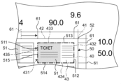
シート40を基準として印刷画像50を配置する場合、まず、基準位置41に最も近くに配置されている成果物の成果物領域43(図2に示す)の位置を設定する。成果物領域43の位置の設定は、一例として、シート40の外形線42の左右方向および上下方向に沿って設けられているバー61を用いて行われる。例えば、図4~図7に示すように、シート40の外形線42の外側に配置されているバー61を移動させて、成果物領域43の外形線431の右辺432および上辺433を成果物の画像51の外形線511のうちの2辺(この実施形態では、成果物の画像51の外形線511の右辺512および上辺513)に一致させる。そして、続いて、図8および図9に示すように、シート40の外形線42の外側に配置されているバー61を移動させて、成果物領域43の外形線431の下辺434および左辺435を成果物の画像51の外形線511のうちの残りの2辺(この実施形態では、外形線511の下辺514および左辺515)に一致させる。成果物領域43の全ての外形線431が成果物の画像51の外形線511に一致すると、シート40に対する印刷画像50の配置が完了する。このように、設定された成果物領域43の位置は、バー61を介して視覚により認識できる。設定された成果物領域43の外形線431は、裁断加工が施される加工位置として設定される。
When placing the
なお、図4は、成果物領域43の外形線431の右辺432を成果物の画像51の外形線511の右辺512に一致させる前の状態を示し、図5は、左右方向のバー61を移動させて、成果物領域43の外形線431の右辺432を成果物の画像51の外形線511の右辺512に一致させた後の状態を示す。また、図6は、成果物領域43の外形線431の上辺433を成果物の画像51の外形線511の上辺513に一致させる前の状態を示し、図7は、上下方向のバー61を移動させて、成果物領域43の外形線431の上辺433を成果物51の外形線511の上辺513に一致させた後の状態を示す。また、図8は、成果物領域43の外形線431の下辺434を成果物の画像51の外形線511の下辺514に一致させる前後の状態を示し、図9は、成果物領域43の外形線431の左辺435を成果物の画像51の外形線511の左辺515に一致させる前後の状態を示す。
4 shows the state before the
基準位置41に最も近くに配置されている成果物領域43の位置が設定されると、加工位置設定部102は、図10~図12に示すように、面付設定を行う。シート40を基準として印刷画像50を配置した場合、面付設定は、例えば、操作者が手動で、または、自動的に、図4~図9で設定した成果物領域43を複製し、全ての成果物の画像51について、複製した成果物領域43の位置を設定することで行われる。面付設定を自動で行う場合、例えば、印刷画像50に含まれる成果物の画像51の配置(この実施形態では、5行2列)を入力することで行われる。
When the position of the
面付設定が行われた後のシート40に対する印刷画像50の配置は、図10に示すように、印刷画像50とシート40の外形とが重なった状態でディスプレイ141に表示される。このとき、ディスプレイ141に表示されている印刷画像50の成果物の画像51に、設定された成果物領域43の位置(すなわち、外形線431)と一致していない成果物の画像51がある場合、ディスプレイ141に表示されている成果物の画像51と、成果物領域43の外形線431とが一致するようにバー61を移動させる。例えば、図11に示すように、ディスプレイ141に表示されている右列の上から2番目の成果物の画像51の外形線511の上辺513が、成果物領域43の外形線431の上辺433と一致していなかったとする。この場合、右列の上から2番目の成果物領域43の外形線431の上辺433に対応する上下方向のバー61を移動させて、図12に示すように、成果物領域43の外形線431の上辺433を成果物の画像51の外形線511の上辺513に一致させる。
The layout of the
ディスプレイ141に表示されている全ての成果物の画像51と、設定された成果物領域43の外形線431とが一致していることが確認されると、シート40に対する印刷画像50の配置と、成果物領域43の配置とが完了する。
When it is confirmed that all the
また、成果物を基準とする場合、シート40を基準として印刷画像50を配置する場合と同様に、成果物領域43の外形線431と成果物の画像51の外形線511とが一致するように、バー61を移動させた後、面付設定を行う。面付設定は、例えば、成果物領域43の外形線431と成果物の画像51とを1つのセットとして複製することで行われる。ディスプレイ141に表示されている全ての成果物の画像51と、設定された成果物領域43の外形線431とが一致していることが確認されると、シート40に対する印刷画像50の配置と、成果物領域43の配置とが完了する。
When using the deliverable as a reference, similar to when placing the
次に、加工位置設定部102は、配置が完了した印刷画像50の各成果物の画像51に対して加工位置を設定する。各成果物の画像51に対する加工位置の設定は、例えば、次のように行う。
Next, the processing
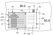
まず、図13および図14に示すように、加工位置設定部102は、印刷画像50の各成果物の画像51と、シート40に施される加工処理の加工位置を示す加工マーク71を少なくとも1つ含む加工マークセットとを同時に表示装置14のディスプレイ141に表示する。この実施形態では、加工位置設定部102は、印刷画像50の各成果物の画像51と、施される加工の加工位置P1~P5を含む加工マークセットとを重ねた状態でディスプレイ141に表示させる。
First, as shown in Figures 13 and 14, the processing
次に、ディスプレイ141に表示されている加工マークを所望の位置に移動させる。図13および図14には、一例として、ミシン目加工の加工位置P5と、加工位置P5に対応する加工マーク71とを示す。加工位置P5の設定は、加工マーク71を所望の位置(例えば、各成果物51の左右方向のグラデーションの境界54)に移動させることで行われる。なお、図13および図14では、加工位置P1~P4については、実線で、加工位置P5および加工位置P5に対応する加工マーク71ついては、点線で示されている。なお、加工位置P1~P4は、前述のとおり、成果物領域43の位置の設定時に、裁断加工が施される加工位置としてそれぞれ設定されるので、ここで改めて設定する必要はない。
Next, the processing mark displayed on the
この実施形態では、加工位置の設定と共に、加工種類も設定される。全ての成果物の画像51に対して、加工位置および加工種類が設定されると、設定された加工位置および加工種類に基づいて、加工ジョブが作成される。
In this embodiment, the processing type is set along with the processing position. Once the processing position and processing type are set for all the
なお、加工マーク71の一端には、加工マーク71と共に移動する略円形状のマーク72が設けられている。このマーク72により、加工マーク71を認識し易くしている。また、マーク72は、加工の種類により変化するように構成され、マーク72の位置に加え、加工の種類も認識し易くしている。なお、図13および図14には、ミシン目加工に対応するマーク72を示している。また、印刷画像50の各成果物の画像51の右上角には、上下方向および左右方向に延びるトンボマーク63(画像マークの一例)が設けられている。加工マーク71とトンボマーク63との間の距離が所定値以下(例えば、1.0mm以下)になった場合、加工位置設定部102は、加工マーク71を自動的に移動させて、加工マーク71とトンボマーク63とを一致させる。
At one end of the
また、加工ジョブ生成装置10では、少なくとも1つの加工マーク71を含む少なくとも1つの加工マークセットと、少なくとも1つの加工マークセットに対応する少なくとも1つの印刷画像50と、シート40の外形を表すシート画像とを重ねた状態で表示装置14に表示させているが、印刷画像50およびシート画像については、表示装置14に表示させないようにすることもできる。例えば、少なくとも1つの加工マーク71を含む少なくとも1つの加工マークセットと、シート40の外形を表示するシート画像とを重ねた状態で表示装置14に表示させてもよい。この場合、例えば、印刷画像50の透明度を変更可能にして、印刷画像50の透明度を100%にすることで、印刷画像50を表示しないようにしてもよい。また、少なくとも1つの加工マーク71を含む加工マークセットと、シート40の情報に関連付けられた印刷画像50とを重ねた状態で表示装置14に表示させてもよい。この場合、例えば、シート画像の透明度を変更可能にして、シート画像の透明度を100%にすることで、シート40を表示しないようにしてもよい。シート画像を表示装置14に表示させて加工位置の設定を行う場合、加工マーク71の位置は、シート40の基準位置41から距離を数値入力することで設定することもできる。
In addition, in the processing
加工ジョブ生成部103は、加工位置設定部102で設定された加工位置に基づいて、加工ジョブを生成する。生成された加工ジョブは、例えば、図15に示すように、シート40に対する印刷画像50の配置の情報と、加工処理が行われる加工位置および加工種類の情報とを含み、ディスプレイ141に重ねた状態で表示することができる。図15に示す加工ジョブには、前述のとおり、縦裁断加工の加工位置P1、P3と、横裁断加工の加工位置P2、P4と、ミシン目加工の加工位置P5とが含まれている。
The processing
本実施形態の加工ジョブ生成装置10によれば、次のような効果を発揮できる。
The processing
加工ジョブ生成装置10によれば、印刷画像50と、シート40に施される加工処理の加工位置を示す加工マーク71とを表示装置14に同時に表示させ、表示装置14に表示された印刷画像50に基づいて加工位置P1~P5の設定を行い、印刷画像50の情報と設定された加工位置P1~P5とに基づいて加工ジョブを生成する。このような構成により、シート40における印刷画像50に対する加工位置P1~P5を直感的に容易に把握できるので、加工ジョブを容易に作成できる加工ジョブ生成装置10を実現できる。
According to the modification
加工位置設定部102が、印刷画像50と加工マーク71とを重ねた状態で表示装置14に表示させる。このような構成により、シート40における印刷画像50に対する加工位置P1~P5をより容易に把握できるので、加工ジョブを容易に作成できる加工ジョブ生成装置10を実現できる。
The processing
加工位置設定部102が、加工マーク71と、印刷画像50に設定されたトンボマーク63との間の距離が所定値以下になった場合、加工マーク71を自動的に移動させて、加工マーク71とトンボマーク63とを一致させる。このような構成により、加工ジョブをより容易に作成することができる。
When the distance between the
取得部101が、サイズを含むシート40の情報を取得し、加工位置設定部102が、少なくとも1つの加工マーク71を含む少なくとも1つの加工マークセットと、シート40の外形を表示するシート画像とを重ねた状態で表示装置14に表示させる。このような構成により、シート40に対する加工マーク71の位置を直感的に容易に把握できる。
The
取得部101が、サイズを含むシート40の情報を取得し、加工位置設定部102が、少なくとも1つの加工マーク71を含む少なくとも1つの加工マークセットと、少なくとも1つの加工マークセットに対応する少なくとも1つの印刷画像50と、シート40の外形を表すシート画像とを重ねた状態で表示装置14に表示させる。このような構成により、シート40に対する印刷画像50および加工マーク71のセットの位置を直感的に容易に把握できる。
The
取得部101が、サイズを含むシート40の情報を取得し、加工位置設定部102が、少なくとも1つの加工マーク71を含む加工マークセットと、シート40の情報に関連付けられた印刷画像50とを重ねた状態で表示装置14に表示させる。このような構成により、シート40および印刷画像50に対する加工マーク71の位置を直感的に容易に把握できる。
The
加工位置設定部102は、取得部101で取得されたシート40のサイズに応じて、表示装置14に表示させるシート40のサイズを変更する。このような構成により、印刷画像50のサイズに応じてシート40のサイズを変更する必要がなくなるので、加工ジョブをより容易に作成することができる。
The processing
加工ジョブを外部に出力する出力部13をさらに備え、出力部13により出力される加工ジョブには、加工位置P1~P5のみ、または、加工位置P1~P5および加工種類、または、加工位置P1~P5および印刷画像の情報、または、加工位置P1~P5、加工種類および印刷画像の情報のいずれかが含まれる。このような構成により、生成した加工ジョブを出力できる。
The system further includes an
本実施形態のシート加工システム1によれば、次のような効果を発揮できる。
The
シート加工システム1によれば、加工ジョブ生成装置10と、シート加工装置30と
を備え、シート加工装置30が、加工ジョブ生成装置10で生成された加工ジョブに基づいてシート40を加工する。このような構成により、シート40を容易に加工できるシート加工システムを実現できる。
The
加工ジョブに基づいて印刷画像50をシート40に印刷して、印刷済シートを生成する印刷装置20をさらに備え、シート加工装置30が、加工ジョブに基づいて、印刷装置20によって生成された印刷済シートを加工する。このような構成により、シート40を容易かつ高精度で加工できる。
The system further includes a
なお、加工ジョブ生成装置10では、加工位置設定部102が面付設定を行っているが、これに限らず、加工位置設定部102が面付設定を行わなくてもよい。この場合、シート加工システム1は、加工ジョブ生成装置10で生成された加工ジョブに基づいて面付を行う印刷画像編集装置(図示せず)を備えてもよい。このような構成により、シート40を容易かつ高精度で加工できる。
In the processing
本実施形態のシート加工システム1は、次のように構成することもできる。
The
加工位置設定部102は、印刷画像50と加工マーク71とを表示装置14に同時に表示させればよく、印刷画像50と加工マーク71とを重ねた状態で表示装置14に表示させる場合に限らない。
The processing
表示装置は、シート加工装置30の表示装置14に限らず、パソコン、スマートフォンまたはタブレットPC等の外部装置のディスプレイであってもよい。
The display device is not limited to the
加工マーク71と、印刷画像50に設定されたトンボマーク63との間の距離が所定値以下になった場合に、加工マーク71を自動的に移動させて、加工マーク71とトンボマーク63とを一致させる機能は、省略することができる。
When the distance between the
画像マークは、トンボマーク63に限らず、任意に設定できる。例えば、印刷画像50の色の変化量が所定値以上の部分を画像マークとしてもよい。
The image mark is not limited to the
出力部13は、例えば、加工ジョブ生成装置10をシート加工装置30と一体に形成することで、省略することができる。
The
シート加工システム1は、加工ジョブ生成装置10とシート加工装置30とを少なくとも備えていればよく、印刷装置20については、省略することができる。
The
取得部101は、シート40の情報に限らず、成果物の情報を取得するように構成してもよい。成果物の情報は、例えば、成果物の画像51のサイズ、成果物の画像51の位置および面付設定の少なくともいずれかを含む。この場合、加工位置設定部102は、成果物の情報に関連付けられた少なくとも1つの加工マークを含む加工マークセットと、印刷画像50とを重ねた状態で表示装置14に表示させることができる。
The
例えば、取得部101が、成果物の画像51のサイズを含む成果物の情報を取得した場合、加工位置設定部102は、図16に示すように、加工マークセットを表示装置14に表示させることができる。図16の加工マークセットは、成果物の画像51と同じサイズで、成果物の画像51の位置情報に関連付けされていない加工マーク71(言い換えると、成果物の画像51の外形線511に一致していない加工マーク71)を含んでいる。
For example, when the
例えば、取得部101が、成果物の画像51のサイズと成果物の画像51の位置とを含む成果物の情報を取得した場合、加工位置設定部102は、図17に示すように、加工マークセットを表示装置14に表示させることができる。図17の加工マークセットは、成果物の画像51と同じサイズで、成果物の画像51の位置情報に関連付けされた加工マーク71(言い換えると、成果物の画像51の外形線511に一致している加工マーク71)を含んでいる。
For example, when the
例えば、取得部101が、面付設定を含む成果物の情報を取得した場合、加工位置設定部102は、図18に示すように、加工マークセットを表示装置14に表示させることができる。図18のマークセットは、成果物の画像51よりも小さいサイズで、成果物の画像51の位置情報に関連付けされていない、面付数と同じ数の加工マーク71を含んでいる。
For example, when the
例えば、取得部101が、面付設定と成果物の画像51のサイズとを含む成果物の情報を取得した場合、加工位置設定部102は、図19に示すように、加工マークセットを表示装置14に表示させることができる。図19のマークセットは、成果物の画像51と同じサイズで、成果物の画像51の位置情報に関連付けされていない、面付数と同じ数の加工マーク71を含んでいる。
For example, when the
例えば、取得部101が、面付設定と成果物の画像51の位置とを含む成果物の情報を取得した場合、加工位置設定部102は、図20に示すように、加工マークセットを表示装置14に表示させることができる。図20のマークセットは、成果物の画像51よりも小さいサイズで、成果物の画像51の位置情報に関連付けされた、面付数と同じ数の加工マーク71を含んでいる。図20では、各加工マーク71の右上の角と、成果物の画像51の外形線511における右上の角とが一致している。
For example, when the
例えば、取得部101が、面付設定と成果物の画像51のサイズと成果物の画像51の位置とを含む成果物の情報を取得した場合、加工位置設定部102は、図21に示すように、加工マークセットを表示装置14に表示させることができる。図21のマークセットは、成果物の画像51と同じサイズで、成果物の画像51の位置情報に関連付けされた、面付数と同じ数の加工マーク71を含んでいる。
For example, when the
取得部101は、成果物の情報から、成果物の画像51が配置されていない印刷画像50の余白領域55(図15に示す)の情報を取得するように構成してもよい。余白領域55の情報は、例えば、シート40の外形線53と成果物の画像51の外形線511との間の距離L1(図15に示す)、および/または、隣接する成果物の画像51の外形線511間の距離L2(図15に示す)を含むことができる。
The
以上のような構成により、シート40における印刷画像50に対する「成果物の画像51および加工マーク71」のセットの位置が直感的に容易に把握できる。
With the above configuration, the position of the set of "image of the
加工位置設定部102は、例えば、操作者により入力された数値に基づいて加工マークの位置を設定可能に構成されていてもよい。数値入力により、ポインティングディバイスなどでは難しい微調整を容易に行えるので、加工マークの位置をより正確に設定できる。
The processing
なお、前記様々な実施形態または変形例のうちの任意の実施形態または変形例を適宜組み合わせることにより、それぞれの有する効果を奏するようにすることができる。また、実施形態同士の組み合わせまたは実施例同士の組み合わせまたは実施形態と実施例との組み合わせが可能であると共に、異なる実施形態または実施例の中の特徴同士の組み合わせも可能である。 In addition, by appropriately combining any of the various embodiments or modifications described above, it is possible to achieve the effects of each. In addition, it is possible to combine embodiments with each other, or to combine examples with each other, and it is also possible to combine features of different embodiments or examples.
本発明では、シートにおける印刷画像に対する加工位置を直感的に容易に把握できて加工ジョブを容易に作成できる加工ジョブ生成装置を提供できるので、産業上の利用価値が大である。 The present invention provides a processing job creation device that can intuitively and easily grasp the processing position for a printed image on a sheet and easily create processing jobs, and is therefore of great industrial value.
1 シート加工システム
10 加工ジョブ生成装置
101 取得部
102 加工位置設定部
103 加工ジョブ生成部
11 CPU
12 記憶部
13 出力部
14 表示装置
141 ディスプレイ
20 印刷装置
30 シート加工装置
40 シート
41 基準位置
42 外形線
43 成果物領域
431 外形線
50 印刷画像
51 成果物の画像
511 成果物の画像の外形線
52 基準位置
53 外形線
54 境界
61 バー
63 トンボマーク
71 加工マーク
72 マーク
P1~P5 加工位置
1
12
Claims (16)
基準位置の情報を含む前記印刷画像の情報と、シートサイズおよび基準位置の情報を含む前記シートの情報とを取得する取得部と、
前記印刷画像と前記シートの外形線とを前記シートに対する印刷位置に合わせて表示すると共に、前記印刷画像と、前記シートの外形線と、前記シートに施される加工処理の加工位置を示す加工マークとを前記表示装置に同時に重ねて表示させ、前記表示装置に表示された前記印刷画像に基づいて、前記印刷画像の所望の位置に前記加工マークを移動させて、前記加工位置の設定を行う加工位置設定部と
を備え、
前記印刷画像の情報と設定された前記加工位置とに基づいて前記加工ジョブを生成する、加工ジョブ生成装置。 A processing job generating device that generates, using a display device, a processing job for a sheet processing device that can process a sheet on which a print image is printed in accordance with the processing job,
an acquisition unit that acquires information about the print image including information about a reference position and information about the sheet including information about a sheet size and a reference position ;
a processing position setting unit that displays the print image and the outline of the sheet in accordance with a printing position relative to the sheet, and simultaneously displays the print image, the outline of the sheet, and a processing mark indicating a processing position of a processing treatment to be applied to the sheet in a superimposed manner on the display device , and moves the processing mark to a desired position of the print image based on the print image displayed on the display device, thereby setting the processing position;
a modification job generating device that generates the modification job based on the print image information and the set modification position.
前記印刷画像と前記加工マークとを重ねた状態で前記表示装置に表示させる、請求項1の加工ジョブ生成装置。 The processing position setting unit,
2. The modification job generating device according to claim 1, wherein the print image and the modification mark are displayed on the display device in an overlapping state.
前記加工マークと、前記印刷画像に設定された画像マークとの間の距離が所定値以下になった場合、前記加工マークを自動的に移動させて、前記加工マークと前記画像マークとを一致させる、請求項1または2の加工ジョブ生成装置。 The processing position setting unit,
3. The processing job generation device of claim 1 or 2, wherein when a distance between the processing mark and an image mark set on the print image becomes equal to or less than a predetermined value, the processing mark is automatically moved so that the processing mark and the image mark are aligned.
前記加工位置設定部が、
少なくとも1つの前記加工マークを含む少なくとも1つの加工マークセットと、前記シートの外形を表すシート画像とを重ねた状態で前記表示装置に表示させる、請求項1から3のいずれか1つの加工ジョブ生成装置。 the acquiring unit acquires information about the sheet including a size,
The processing position setting unit,
4. The processing job generation device according to claim 1, further comprising: displaying, on the display device, at least one processing mark set including at least one of the processing marks and a sheet image representing the outline of the sheet in an overlapping state.
前記加工位置設定部が、
前記少なくとも1つの加工マークセットと、前記少なくとも1つの加工マークセットに対応する少なくとも1つの前記印刷画像と、前記シート画像とを重ねた状態で前記表示装置に表示させる、請求項4の加工ジョブ生成装置。 the acquiring unit acquires information about the sheet including a size,
The processing position setting unit,
The processing job generation device according to claim 4 , further comprising means for displaying, on the display device, the at least one processing mark set, the at least one print image corresponding to the at least one processing mark set, and the sheet image in an overlapping state.
前記加工位置設定部が、
少なくとも1つの前記加工マークを含む加工マークセットと、前記シートの情報に関連付けられた前記印刷画像とを重ねた状態で前記表示装置に表示させる、請求項1から3のいずれか1つの加工ジョブ生成装置。 the acquiring unit acquires information about the sheet including a size,
The processing position setting unit,
4. The processing job generation device according to claim 1, further comprising: a processing mark set including at least one of the processing marks and the print image associated with information on the sheet are displayed on the display device in an overlapping state.
前記取得部で取得された前記シートのサイズに応じて、前記表示装置に表示させる前記シートのサイズを変更する、請求項4から6のいずれか1つの加工ジョブ生成装置。 The processing position setting unit is
7. The modification job generating device according to claim 4, further comprising: a display unit configured to change a size of the sheet displayed on the display unit in accordance with the size of the sheet acquired by the acquisition unit.
前記取得部が、前記成果物の画像のサイズおよび面付設定の少なくとも一方を含む前記成果物の情報を取得し、
前記加工位置設定部が、
前記成果物の情報に関連付けられた少なくとも1つの前記加工マークを含む加工マークセットと、前記印刷画像とを重ねた状態で前記表示装置に表示させる、請求項1から3のいずれか1つの加工ジョブ生成装置。 the print image includes an image of at least one deliverable;
the acquiring unit acquires information about the deliverable including at least one of a size of an image of the deliverable and an imposition setting;
The processing position setting unit,
4. The processing job generation device according to claim 1, further comprising: a processing mark set including at least one of the processing marks associated with the information of the final product and the print image superimposed on the display device.
前記加工位置設定部が、
前記余白領域の情報に関連付けられた前記加工マークセットと、前記印刷画像とを重ねた状態で前記表示装置に表示させる、請求項9の加工ジョブ生成装置。 the acquiring unit acquires information on a margin area of the print image where an image of the final product is not arranged from the information on the final product,
The processing position setting unit,
The modification job generation device according to claim 9 , further comprising means for displaying, on the display device, the modification mark set associated with the information on the blank space and the print image in an overlapping state.
前記取得部が、前記成果物の画像が配置されていない前記印刷画像の余白領域の情報を取得し、
前記余白領域の情報は、前記シートの外形線と前記成果物の画像の外形線との間の距離を含み、
前記加工位置設定部が、
前記余白領域の情報に関連付けられた少なくとも1つの前記加工マークを含む加工マークセットと、前記印刷画像とを重ねた状態で前記表示装置に表示させる、請求項1から3のいずれか1つの加工ジョブ生成装置。 the print image includes an image of at least one deliverable;
The acquisition unit acquires information about a margin area of the print image in which an image of the final product is not placed,
The margin area information includes a distance between an outline of the sheet and an outline of the image of the deliverable,
The processing position setting unit,
4. The processing job generation device according to claim 1, further comprising: a processing mark set including at least one of the processing marks associated with information on the margin area and the print image, the processing mark set being displayed on the display device in an overlapping state.
前記取得部が、前記成果物の画像が配置されていない前記印刷画像の余白領域の情報を取得し、
前記余白領域の情報は、前記シートの外形線と前記成果物の画像の外形線との間の距離、および、隣接する前記成果物の画像の外形線間の距離の少なくとも一方を含み、
前記加工位置設定部が、
前記余白領域の情報に関連付けられた少なくとも1つの前記加工マークを含む加工マークセットと、前記印刷画像とを重ねた状態で前記表示装置に表示させる、請求項1から3のいずれか1つの加工ジョブ生成装置。 The print image includes a plurality of images of the deliverables,
The acquisition unit acquires information about a margin area of the print image in which an image of the final product is not placed,
The information on the margin area includes at least one of a distance between an outline of the sheet and an outline of the image of the deliverable, and a distance between the outlines of adjacent images of the deliverable,
The processing position setting unit,
4. The processing job generation device according to claim 1, further comprising: a processing mark set including at least one of the processing marks associated with information on the margin area and the print image, the processing mark set being displayed on the display device in an overlapping state.
前記加工位置設定部は、複数の前記成果物に対して面付設定を行い、行われた前記面付設定に基づいて、一度の操作で複数の前記成果物に対する加工位置が設定されるように構成されている、請求項1から3のいずれか1つの加工ジョブ生成装置。4. The processing job generation device according to claim 1, wherein the processing position setting unit is configured to perform imposition setting for the plurality of deliverables, and to set processing positions for the plurality of deliverables with a single operation based on the imposition setting.
入力された数値に基づいて前記加工マークの位置を設定可能に構成されている、請求項1から13のいずれか1つの加工ジョブ生成装置。 The processing position setting unit,
14. The modification job generating device according to claim 1, further comprising a function for setting the position of the modification mark based on an inputted numerical value.
前記出力部により出力される前記加工ジョブには、前記加工位置のみ、または、前記加工位置および加工種類、または、前記加工位置および前記印刷画像の情報、または、前記加工位置、前記加工種類および前記印刷画像の情報のいずれかが含まれる、請求項1から14のいずれか1つの加工ジョブ生成装置。 An output unit that outputs the processing job to an outside,
15. The processing job generation device of claim 1, wherein the processing job output by the output unit includes only the processing position, or the processing position and the processing type, or the processing position and information on the print image, or the processing position, the processing type, and information on the print image.
前記シート加工装置と
を少なくとも備え、
前記シート加工装置が、前記加工ジョブ生成装置で生成された前記加工ジョブに基づいて前記シートを加工する、シート加工システム。 A modification job generating device according to any one of claims 1 to 15 ,
The sheet processing device includes at least the sheet processing device.
The sheet processing system includes a sheet processing device that processes the sheet based on the processing job generated by the processing job generating device.
Applications Claiming Priority (2)
| Application Number | Priority Date | Filing Date | Title |
|---|---|---|---|
| JP2019184489 | 2019-10-07 | ||
| JP2019184489 | 2019-10-07 |
Publications (2)
| Publication Number | Publication Date |
|---|---|
| JP2021059006A JP2021059006A (en) | 2021-04-15 |
| JP7549869B2 true JP7549869B2 (en) | 2024-09-12 |
Family
ID=72752372
Family Applications (1)
| Application Number | Title | Priority Date | Filing Date |
|---|---|---|---|
| JP2020168833A Active JP7549869B2 (en) | 2019-10-07 | 2020-10-06 | Processing job generation device and sheet processing system |
Country Status (3)
| Country | Link |
|---|---|
| US (1) | US11604616B2 (en) |
| EP (1) | EP3805912B1 (en) |
| JP (1) | JP7549869B2 (en) |
Citations (11)
| Publication number | Priority date | Publication date | Assignee | Title |
|---|---|---|---|---|
| JP2000293104A (en) | 1999-04-05 | 2000-10-20 | Susumu Kosukegawa | Seal preparing device |
| JP2002125111A (en) | 2000-10-12 | 2002-04-26 | Toyo Ink Mfg Co Ltd | Method and apparatus for automatically adjusting positioning mark |
| JP4254611B2 (en) | 2003-06-06 | 2009-04-15 | セイコーエプソン株式会社 | Printing system with processing function, image processing apparatus, processing printing program, image processing program, and processing printing method |
| JP4498691B2 (en) | 2003-06-12 | 2010-07-07 | 大日本印刷株式会社 | Imposition system and method |
| JP2016221658A (en) | 2015-06-03 | 2016-12-28 | ブラザー工業株式会社 | Cutting device, and cutting data generating program |
| WO2017098877A1 (en) | 2015-12-10 | 2017-06-15 | セイコーエプソン株式会社 | Information processing device, program, cut configuring method using information processing device, and printing system |
| US20170341375A1 (en) | 2016-05-24 | 2017-11-30 | Océ Holding B.V. | Method of printing a print job with digital finishing visualization images |
| JP2018120393A (en) | 2017-01-25 | 2018-08-02 | ローランドディー.ジー.株式会社 | program |
| JP2019139725A (en) | 2018-02-07 | 2019-08-22 | 大日本印刷株式会社 | Print operation terminal, and print system |
| JP2019169857A (en) | 2018-03-23 | 2019-10-03 | 京セラドキュメントソリューションズ株式会社 | Image forming apparatus |
| JP6747096B2 (en) | 2016-06-29 | 2020-08-26 | コニカミノルタ株式会社 | Image forming apparatus and control program therefor |
Family Cites Families (9)
| Publication number | Priority date | Publication date | Assignee | Title |
|---|---|---|---|---|
| JP4880396B2 (en) * | 2006-08-03 | 2012-02-22 | 株式会社リコー | Image processing apparatus, program, and preview image display method |
| JP5554982B2 (en) * | 2009-12-22 | 2014-07-23 | キヤノン株式会社 | Printing control apparatus, printing apparatus control method, and program |
| JP5542177B2 (en) * | 2012-07-10 | 2014-07-09 | 富士フイルム株式会社 | DATA GENERATION DEVICE, DATA GENERATION METHOD, AND PROGRAM |
| JP5802698B2 (en) * | 2013-04-16 | 2015-10-28 | 富士フイルム株式会社 | Data editing apparatus, data editing method, and program |
| JP2015007951A (en) * | 2013-05-31 | 2015-01-15 | 富士フイルム株式会社 | Imposition apparatus, method and program |
| JP2018074517A (en) | 2016-11-02 | 2018-05-10 | 京セラドキュメントソリューションズ株式会社 | Image forming apparatus |
| JP7094733B2 (en) * | 2018-03-13 | 2022-07-04 | キヤノン株式会社 | Image processing device, program, image processing method |
| JP7240109B2 (en) * | 2018-07-06 | 2023-03-15 | キヤノン株式会社 | Information processing device, system, display method and program |
| JP7321814B2 (en) * | 2019-07-26 | 2023-08-07 | キヤノン株式会社 | Information processing device, control method, printing system, and program |
-
2020
- 2020-10-05 EP EP20200131.9A patent/EP3805912B1/en active Active
- 2020-10-06 US US17/063,832 patent/US11604616B2/en active Active
- 2020-10-06 JP JP2020168833A patent/JP7549869B2/en active Active
Patent Citations (11)
| Publication number | Priority date | Publication date | Assignee | Title |
|---|---|---|---|---|
| JP2000293104A (en) | 1999-04-05 | 2000-10-20 | Susumu Kosukegawa | Seal preparing device |
| JP2002125111A (en) | 2000-10-12 | 2002-04-26 | Toyo Ink Mfg Co Ltd | Method and apparatus for automatically adjusting positioning mark |
| JP4254611B2 (en) | 2003-06-06 | 2009-04-15 | セイコーエプソン株式会社 | Printing system with processing function, image processing apparatus, processing printing program, image processing program, and processing printing method |
| JP4498691B2 (en) | 2003-06-12 | 2010-07-07 | 大日本印刷株式会社 | Imposition system and method |
| JP2016221658A (en) | 2015-06-03 | 2016-12-28 | ブラザー工業株式会社 | Cutting device, and cutting data generating program |
| WO2017098877A1 (en) | 2015-12-10 | 2017-06-15 | セイコーエプソン株式会社 | Information processing device, program, cut configuring method using information processing device, and printing system |
| US20170341375A1 (en) | 2016-05-24 | 2017-11-30 | Océ Holding B.V. | Method of printing a print job with digital finishing visualization images |
| JP6747096B2 (en) | 2016-06-29 | 2020-08-26 | コニカミノルタ株式会社 | Image forming apparatus and control program therefor |
| JP2018120393A (en) | 2017-01-25 | 2018-08-02 | ローランドディー.ジー.株式会社 | program |
| JP2019139725A (en) | 2018-02-07 | 2019-08-22 | 大日本印刷株式会社 | Print operation terminal, and print system |
| JP2019169857A (en) | 2018-03-23 | 2019-10-03 | 京セラドキュメントソリューションズ株式会社 | Image forming apparatus |
Also Published As
| Publication number | Publication date |
|---|---|
| EP3805912B1 (en) | 2026-01-28 |
| EP3805912A1 (en) | 2021-04-14 |
| US20210103412A1 (en) | 2021-04-08 |
| US11604616B2 (en) | 2023-03-14 |
| JP2021059006A (en) | 2021-04-15 |
Similar Documents
| Publication | Publication Date | Title |
|---|---|---|
| JP5758940B2 (en) | Image editing apparatus, method and program | |
| CN104077086A (en) | Data generation apparatus, data generation method, and program | |
| JP6661474B2 (en) | Print control device, control method of print control device, and program | |
| JP5656911B2 (en) | Image editing apparatus, method and program | |
| JP5779378B2 (en) | Imposition template, imposition data generation apparatus, imposition data generation method and program | |
| JP7549869B2 (en) | Processing job generation device and sheet processing system | |
| US9030708B2 (en) | Imposition apparatus, imposition method, and non-transitory computer-readable recording medium | |
| JP2014072793A (en) | Image processing device and program | |
| JP6544224B2 (en) | Layout data creation apparatus, layout data creation method and layout data creation program | |
| US9760317B2 (en) | Page allocation table determining apparatus, page allocation table determining method, and non-transitory storage medium storing page allocation table determining program | |
| JP6432437B2 (en) | Written data processing device | |
| JPS5916075A (en) | Slip designing system | |
| JP2011242936A (en) | Plate inspection support method, device and program therefor | |
| JP5940512B2 (en) | Imposition apparatus, method and program | |
| JP2022164010A (en) | Program, information processing apparatus, and control method for information processing apparatus | |
| JP2858403B2 (en) | Document processing device | |
| JP2013182419A (en) | Image layout system, image editor device, and page layout device | |
| JP2008023791A (en) | Image forming apparatus, image forming method, and image forming program | |
| JP2006198804A (en) | Misalignment measuring method, misalignment correction device and misalignment correction program | |
| JP6626664B2 (en) | Image display device, image display method, and image display program | |
| JPH01173152A (en) | Magazine editing system | |
| JP2015185031A (en) | Envelope printing program, recording medium, and data processing device | |
| JPH051947B2 (en) | ||
| JPS63182770A (en) | Document production/output device | |
| JPH0245866A (en) | Editing method for document in editing machine |
Legal Events
| Date | Code | Title | Description |
|---|---|---|---|
| RD04 | Notification of resignation of power of attorney |
Free format text: JAPANESE INTERMEDIATE CODE: A7424 Effective date: 20230711 |
|
| RD03 | Notification of appointment of power of attorney |
Free format text: JAPANESE INTERMEDIATE CODE: A7423 Effective date: 20230714 |
|
| A621 | Written request for application examination |
Free format text: JAPANESE INTERMEDIATE CODE: A621 Effective date: 20230810 |
|
| A977 | Report on retrieval |
Free format text: JAPANESE INTERMEDIATE CODE: A971007 Effective date: 20240524 |
|
| A131 | Notification of reasons for refusal |
Free format text: JAPANESE INTERMEDIATE CODE: A131 Effective date: 20240611 |
|
| A521 | Request for written amendment filed |
Free format text: JAPANESE INTERMEDIATE CODE: A523 Effective date: 20240730 |
|
| TRDD | Decision of grant or rejection written | ||
| A01 | Written decision to grant a patent or to grant a registration (utility model) |
Free format text: JAPANESE INTERMEDIATE CODE: A01 Effective date: 20240813 |
|
| A61 | First payment of annual fees (during grant procedure) |
Free format text: JAPANESE INTERMEDIATE CODE: A61 Effective date: 20240826 |
|
| R150 | Certificate of patent or registration of utility model |
Ref document number: 7549869 Country of ref document: JP Free format text: JAPANESE INTERMEDIATE CODE: R150 |