JP7549147B2 - Treatment Equipment - Google Patents
Treatment Equipment Download PDFInfo
- Publication number
- JP7549147B2 JP7549147B2 JP2023532897A JP2023532897A JP7549147B2 JP 7549147 B2 JP7549147 B2 JP 7549147B2 JP 2023532897 A JP2023532897 A JP 2023532897A JP 2023532897 A JP2023532897 A JP 2023532897A JP 7549147 B2 JP7549147 B2 JP 7549147B2
- Authority
- JP
- Japan
- Prior art keywords
- stent graft
- cover
- stent
- graft
- shaft
- Prior art date
- Legal status (The legal status is an assumption and is not a legal conclusion. Google has not performed a legal analysis and makes no representation as to the accuracy of the status listed.)
- Active
Links
Images


Classifications
-
- A—HUMAN NECESSITIES
- A61—MEDICAL OR VETERINARY SCIENCE; HYGIENE
- A61F—FILTERS IMPLANTABLE INTO BLOOD VESSELS; PROSTHESES; DEVICES PROVIDING PATENCY TO, OR PREVENTING COLLAPSING OF, TUBULAR STRUCTURES OF THE BODY, e.g. STENTS; ORTHOPAEDIC, NURSING OR CONTRACEPTIVE DEVICES; FOMENTATION; TREATMENT OR PROTECTION OF EYES OR EARS; BANDAGES, DRESSINGS OR ABSORBENT PADS; FIRST-AID KITS
- A61F2/00—Filters implantable into blood vessels; Prostheses, i.e. artificial substitutes or replacements for parts of the body; Appliances for connecting them with the body; Devices providing patency to, or preventing collapsing of, tubular structures of the body, e.g. stents
- A61F2/02—Prostheses implantable into the body
- A61F2/04—Hollow or tubular parts of organs, e.g. bladders, tracheae, bronchi or bile ducts
- A61F2/06—Blood vessels
- A61F2/07—Stent-grafts
-
- A—HUMAN NECESSITIES
- A61—MEDICAL OR VETERINARY SCIENCE; HYGIENE
- A61F—FILTERS IMPLANTABLE INTO BLOOD VESSELS; PROSTHESES; DEVICES PROVIDING PATENCY TO, OR PREVENTING COLLAPSING OF, TUBULAR STRUCTURES OF THE BODY, e.g. STENTS; ORTHOPAEDIC, NURSING OR CONTRACEPTIVE DEVICES; FOMENTATION; TREATMENT OR PROTECTION OF EYES OR EARS; BANDAGES, DRESSINGS OR ABSORBENT PADS; FIRST-AID KITS
- A61F2/00—Filters implantable into blood vessels; Prostheses, i.e. artificial substitutes or replacements for parts of the body; Appliances for connecting them with the body; Devices providing patency to, or preventing collapsing of, tubular structures of the body, e.g. stents
- A61F2/95—Instruments specially adapted for placement or removal of stents or stent-grafts
- A61F2/962—Instruments specially adapted for placement or removal of stents or stent-grafts having an outer sleeve
- A61F2/966—Instruments specially adapted for placement or removal of stents or stent-grafts having an outer sleeve with relative longitudinal movement between outer sleeve and prosthesis, e.g. using a push rod
Landscapes
- Health & Medical Sciences (AREA)
- Engineering & Computer Science (AREA)
- Biomedical Technology (AREA)
- Cardiology (AREA)
- Oral & Maxillofacial Surgery (AREA)
- Transplantation (AREA)
- Heart & Thoracic Surgery (AREA)
- Vascular Medicine (AREA)
- Life Sciences & Earth Sciences (AREA)
- Animal Behavior & Ethology (AREA)
- General Health & Medical Sciences (AREA)
- Public Health (AREA)
- Veterinary Medicine (AREA)
- Gastroenterology & Hepatology (AREA)
- Pulmonology (AREA)
- Media Introduction/Drainage Providing Device (AREA)
- Prostheses (AREA)
Description
本発明は、例えば動脈解離(解離性の動脈瘤)等の治療の際に用いられる治療装置に関する。 The present invention relates to a treatment device used in treating, for example, arterial dissection (dissecting aneurysm).
近年、血管や生体内の他の管状器官に狭窄や閉塞が起こった場合や、血管に解離性の動脈瘤等が生じた場合に、線材(素線)などからなるステントをその患部に留置することで、管状器官の管腔を拡張・保持したり、動脈瘤等の破裂を防止することを可能とする手法(ステント留置術)が用いられている。特に、例えば血管における動脈解離等の治療の際には、そのようなステントを覆う筒状のグラフトが設けられた、ステントグラフトが用いられる。In recent years, when stenosis or blockage occurs in blood vessels or other tubular organs in the body, or when a dissecting aneurysm occurs in a blood vessel, a technique known as stent placement has been used in which a stent made of wire (element wire) is placed at the affected area to expand and maintain the lumen of the tubular organ or prevent the rupture of an aneurysm. In particular, when treating arterial dissection in a blood vessel, for example, a stent graft with a tubular graft that covers the stent is used.
ところで、最近では、胸部大動脈における動脈解離等の治療方法の1つとして、OSG(Open Stent Graft)法が提案されている。このOSG法では、開胸後に大動脈を切開し、その切開部からステントグラフトを挿入するとともに、そのステントグラフトの基端側と患者の血管とを縫合することで吻合し、更に必要に応じてこのステントグラフトとは別の人工血管をこの吻合部分と吻合するようになっている。Recently, the Open Stent Graft (OSG) method has been proposed as one of the treatment methods for aortic dissection in the thoracic aorta. In this OSG method, the aorta is incised after the chest is opened, a stent graft is inserted through the incision, and the base end of the stent graft is sutured to the patient's blood vessel to form an anastomosis, and if necessary, an artificial blood vessel separate from the stent graft is anastomosed to the anastomosis.
また、このようなOSG法を利用した手技では、例えば特許文献1に開示されているようなデリバリ用のカテーテルが用いられる。このカテーテルには、上記した切開部からステントグラフトを挿入する際に、縮径された状態のステントグラフトがマウント(保持)されるようになっている。In addition, in such procedures using the OSG method, a delivery catheter such as that disclosed in
ところで、このようなデリバリ用のカテーテル等の治療装置では一般に、治療の際の利便性を向上させることが求められている。したがって、このような治療の際の利便性を向上させることを可能とする提案が望まれる。However, in general, there is a demand for improved convenience during treatment with such treatment devices, such as delivery catheters. Therefore, proposals that make it possible to improve the convenience during such treatment are desirable.
治療の際の利便性を向上させることが可能な治療装置を提供することが望ましい。 It is desirable to provide a treatment device that can improve convenience during treatment.
本発明の一実施の形態に係る治療装置は、軸方向に沿って延在するシャフトを有するカテーテルと、筒状のグラフトとステントとを含んで構成されたステントグラフトと、シャフトの先端領域においてステントグラフトを縮径状態にて保持するためのものであり、軸方向に沿って互いに分離配置されている第1および第2のカバーと、を備えている。第1のカバーは、軸方向に沿って第2のカバーの基端側に配置されている。第2のカバーは、シャフトの外周側に位置する筒状の外層部と、外層部およびシャフトの内周側に位置しており、シャフト内を介してカテーテルの基端側まで延在している内層部と、シャフトの先端側において外層部と内層部とを繋ぐ折り返し部と、を有している。第1のカバーとシャフトとの間、および、第2のカバーにおける外層部とシャフトとの間にそれぞれ、ステントグラフトが縮径状態で保持されるようになっている。また、ステントグラフトの一部に、グラフトおよびステントのうちの少なくともグラフトが配置されていない、窓部が設けられていると共に、縮径状態のステントグラフトにおいて、窓部の先端が、第1および第2のカバー同士の境界付近に位置している。 A treatment device according to an embodiment of the present invention includes a catheter having a shaft extending in an axial direction, a stent graft including a cylindrical graft and a stent, and first and second covers arranged separately from each other along the axial direction for holding the stent graft in a reduced diameter state at the distal end region of the shaft. The first cover is arranged on the proximal end side of the second cover along the axial direction. The second cover has a cylindrical outer layer portion located on the outer periphery side of the shaft, an inner layer portion located on the inner periphery side of the outer layer portion and the shaft and extending through the shaft to the proximal end side of the catheter, and a folded portion connecting the outer layer portion and the inner layer portion at the distal end side of the shaft. The stent graft is held in a reduced diameter state between the first cover and the shaft, and between the outer layer portion of the second cover and the shaft, respectively. In addition, a window portion is provided in a portion of the stent graft in which at least the graft of the graft and stent is not positioned, and in the stent graft in a reduced diameter state, the tip of the window portion is located near the boundary between the first and second covers.
本発明の一実施の形態に係る治療装置では、上記シャフトの先端領域において上記ステントグラフトを縮径状態にて保持するためのカバーが、上記軸方向に沿って基端側の上記第1のカバーと、上記軸方向に沿って先端側の上記第2のカバーとに、分離配置されている。また、上記第1のカバーと上記シャフトとの間、および、上記第2のカバーにおける上記外層部と上記シャフトとの間にそれぞれ、上記ステントグラフトが上記縮径状態で保持されている。これにより、第1のカバーにおける基端側をシャフトの基端方向へと引っ張ると共に、第2のカバーの内層部における基端側をカテーテルの基端方向へと引っ張る操作(引っ張り操作)によって、縮径状態のステントグラフトが第1および第2のカバー内から展開されて拡径する際に、以下のようになる。すなわち、第1および第2のカバー同士の境界付近(ステントグラフトにおける中間位置付近)へ向けて、上記軸方向に沿ってステントグラフトが引っ張られることになる。その結果、拡径されたステントグラフトが患者体内に留置される際に、ステントグラフトの留置位置のずれ(軸方向への位置ずれ)が、抑制される。また、上記ステントグラフトの一部に、グラフトおよびステントのうちの少なくともグラフトが配置されていない、窓部が設けられていることで、以下のようになる。すなわち、例えば、ステントグラフトが留置される血管(動脈等)からの分岐部分(例えば、弓部分岐)に対しても、上記窓部から血液が流れるようになる。したがって、この分岐部分の再建処置(人工血管との吻合処置等)が不要となるため、治療の際の手術時間の短縮化や、侵襲の低減が図られることになる。更に、上記縮径状態のステントグラフトにおいて、上記窓部の先端が、上記第1および第2のカバー同士の境界付近に、位置している。これにより、上記した引っ張り操作によって、縮径状態のステントグラフトが第1および第2のカバー内から展開されて拡径する際に、上記したように、第1および第2のカバー同士の境界付近へ向けてステントグラフトが引っ張られることから、以下のようになる。すなわち、このような境界付近に上記窓部の先端が位置していることから、拡径されたステントグラフトが患者体内に留置される際に、上記窓部の位置ずれ(上記軸方向への位置ずれ)が、抑制される。その結果、治療の際の利便性が更に向上することになる。 In the treatment device according to one embodiment of the present invention, covers for holding the stent graft in a reduced diameter state in the distal region of the shaft are separately arranged as the first cover on the base end side along the axial direction and the second cover on the tip end side along the axial direction. The stent graft is held in the reduced diameter state between the first cover and the shaft, and between the outer layer of the second cover and the shaft. As a result, when the stent graft in the reduced diameter state is deployed from within the first and second covers and expanded in diameter by an operation (pulling operation) of pulling the base end side of the first cover toward the base end direction of the shaft and pulling the base end side of the inner layer of the second cover toward the base end direction of the catheter, the following occurs. That is, the stent graft is pulled along the axial direction toward the vicinity of the boundary between the first and second covers (near the middle position of the stent graft). As a result, when the expanded stent graft is placed in the patient's body, the displacement of the placement position of the stent graft (axial displacement) is suppressed. In addition, by providing a window portion in which at least the graft of the graft and the stent is not placed in a part of the stent graft, the following occurs. That is, for example, blood flows from the window portion to a branch portion (e.g., an arch branch) from a blood vessel (artery, etc.) in which the stent graft is placed. Therefore, reconstruction treatment of this branch portion (anastomosis treatment with an artificial blood vessel, etc.) is not required, and therefore the operation time during treatment can be shortened and the invasiveness can be reduced. Furthermore, in the stent graft in the reduced diameter state, the tip of the window portion is located near the boundary between the first and second covers. As a result, when the stent graft in the reduced diameter state is deployed from within the first and second covers and expanded by the pulling operation, the stent graft is pulled toward the boundary between the first and second covers as described above, and the following occurs. In other words, since the tip of the fenestration is located near such a boundary, the positional displacement (axial displacement) of the fenestration is suppressed when the expanded stent graft is placed in the patient's body, thereby further improving the convenience during treatment.
本発明の一実施の形態に係る治療装置では、上記第1のカバーにおける基端側をシャフトの基端方向へと引っ張る操作である、第1の引っ張り操作と、上記第2のカバーの内層部における基端側をカテーテルの基端方向へと引っ張る操作である、第2の引っ張り操作と、がそれぞれ行われることによって、縮径状態のステントグラフトが、上記第1および第2のカバー内からそれぞれ展開されて、拡径するようになっていてもよい。このようにした場合、上記引っ張り操作としての上記第1および第2の引っ張り操作がそれぞれ行われることによって、縮径状態のステントグラフトが第1および第2のカバー内から展開されて拡径する際に、上記したようにして、ステントグラフトの留置位置のずれが抑制されることになる。In a treatment device according to one embodiment of the present invention, a first pulling operation, which is an operation of pulling the base end side of the first cover toward the base end direction of the shaft, and a second pulling operation, which is an operation of pulling the base end side of the inner layer of the second cover toward the base end direction of the catheter, may be performed, so that the stent graft in the reduced diameter state is deployed from within the first and second covers, respectively, and expanded in diameter. In this case, when the stent graft in the reduced diameter state is deployed from within the first and second covers and expanded in diameter by performing the first and second pulling operations as the pulling operations, respectively, the displacement of the placement position of the stent graft is suppressed as described above.
この場合において、上記第2の引っ張り操作が開始された後に上記第1の引っ張り操作が開始されることによって、縮径状態のステントグラフトが、上記第2および第1のカバー内からそれぞれ、この順序にて展開され、拡径されるようになっていてもよい。このようにした場合、上記したステントグラフトの留置位置のずれが、更に抑制され易くなる結果、治療の際の利便性が更に向上することになる。In this case, the first pulling operation may be started after the second pulling operation, so that the stent graft in the contracted state is deployed and expanded from within the second and first covers, respectively, in that order. In this way, the displacement of the placement position of the stent graft is further suppressed, thereby further improving convenience during treatment.
本発明の一実施の形態に係る治療装置によれば、上記シャフトの先端領域において上記ステントグラフトを縮径状態にて保持するためのカバーが、上記第1および第2のカバーに分離配置されているようにしたので、患者体内でのステントグラフトの留置位置のずれを、抑制することができる。よって、そのような第1および第2のカバーを備えた治療装置を用いて治療を行うことで、治療の際の利便性を向上させることが可能となる。 According to one embodiment of the treatment device of the present invention, the covers for holding the stent graft in a reduced diameter state in the distal end region of the shaft are arranged separately in the first and second covers, so that it is possible to suppress the displacement of the placement position of the stent graft in the patient's body. Therefore, by performing treatment using a treatment device equipped with such first and second covers, it is possible to improve convenience during treatment.
以下、本発明の実施の形態について、図面を参照して詳細に説明する。なお、説明は以下の順序で行う。
1.実施の形態(互いに分離配置された2種類のカバーを有する治療装置の例)
2.変形例(治療装置に適用されるステントグラフトの他の構成例)
3.その他の変形例
DETAILED DESCRIPTION OF THE PREFERRED EMBODIMENTS Hereinafter, preferred embodiments of the present invention will be described in detail with reference to the accompanying drawings. The description will be given in the following order.
1. Embodiment (Example of a treatment device having two types of covers arranged separately from each other)
2. Modifications (other configuration examples of stent grafts applied to treatment devices)
3. Other Modifications
<1.実施の形態>
[概略構成]
図1は、本発明の一実施の形態に係る治療装置(治療装置4)の概略構成例を、模式的に側面図で表したものである。治療装置4は、例えばOSG法を利用した動脈解離等の治療の際に用いられる装置であり、この例では図1に示したように、カテーテル1(デリバリカテーテル)、ステントグラフト2およびカバー3を備えている。なお、このステントグラフト2は、詳細は後述するが、例えば上記した治療の際に、カテーテル1を用いて、治療対象の部位(例えば動脈等の血管内)に留置されるようになっている。
1. Preferred embodiment
[General Configuration]
Fig. 1 is a schematic side view showing an example of the schematic configuration of a treatment device (treatment device 4) according to one embodiment of the present invention. The
(カテーテル1)
カテーテル1は、患者における上記した治療対象の部位までステントグラフト2を運ぶ際に使用される医療機器である。このカテーテル1は、図1に示したように、デリバリシャフト11およびハンドル12(把持部,グリップ)を備えている。なお、デリバリシャフト11は、本発明における「シャフト」の一具体例に対応している。
(Catheter 1)
The
デリバリシャフト11は、可撓性を有する管状構造(管状部材)からなり、自身の軸方向(長手方向)であるZ軸方向に沿って延在(延伸)する形状となっている。このデリバリシャフト11における軸方向に沿った先端領域では、上記した治療の際に、図1に示したように、後述するステントグラフト2が縮径された状態で、後述するカバー3の内部に保持されるようになっている。また、デリバリシャフト11における基端領域は、ハンドル12内に収容された部分に対応している。なお、このような先端領域と基端領域との間の中間領域は、図1に示したように、カバー3とハンドル12との間に位置する領域であり、外部に露出した領域となっている。The
このようなデリバリシャフト11の軸方向に沿った長さ(全長)は、例えば300~900mm程度であり、好ましくは400~800mm程度、更に好ましくは450~750mm程度であり、好適な一例を示せば、670mmである。また、上記した先端領域の長さは、搭載されるステントグラフト2の長さに応じて適宜設定されるようになっており、例えば30~300mm程度であり、好ましくは50~270mm程度、更に好ましくは80~250mm程度である。上記した中間領域の長さは、例えば100~600mm程度であり、好ましくは150~550mm程度、更に好ましくは200~500mm程度であり、好適な一例を示せば、260mmである。The length (total length) of such a
また、上記した先端領域の外径は、例えば5~20mm程度であり、好ましくは8~15mm程度、好適な一例を示せば、11mmである。上記した中間領域の外径は、例えば5~20mm程度であり、好ましくは8~15mm程度、好適な一例を示せば、10mmである。The outer diameter of the tip region is, for example, about 5 to 20 mm, preferably about 8 to 15 mm, and a suitable example is 11 mm. The outer diameter of the intermediate region is, for example, about 5 to 20 mm, preferably about 8 to 15 mm, and a suitable example is 10 mm.
ハンドル12は、図1に示したように、デリバリシャフト11の基端部分(基端領域)に装着されており、カテーテル1の使用時に操作者(医師)が掴む(握る)部分である。このハンドル12は、その軸方向(Z軸方向)に沿って延在する形状となっている。1, the
ハンドル12の軸方向に沿った長さは、例えば50~200mm程度であり、好ましくは60~180mm程度、更に好ましくは80~150mm程度であり、好適な一例を示せば、130mmである。また、ハンドル12の外径は、例えば3~30mm程度であり、好ましくは5~25mm程度、好適な一例を示せば、20mmである。なお、このようなハンドル12は、例えば、ポリカーボネート、アクリロニトリル-ブタジエン-スチレン共重合体(ABS)等の合成樹脂により構成されている。The length of the
ここで、図2は、図1に示したカバー3の内部の詳細構成例等を、模式的に側面図で表したものである。また、図3は、図1に示したステントグラフト2の詳細構成例を、模式的に表したものである。
Here, Fig. 2 is a schematic side view showing an example of the detailed internal configuration of the
(ステントグラフト2)
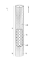
ステントグラフト2は、図1,図3に示したように、その軸方向(Z軸方向)に沿って延在する筒状(円筒状)構造を有しており、ステント21およびグラフト22を含んで構成されている。また、このステントグラフト2は、縮径状態で保持されることが可能な、自己拡張型の構造を有している。なお、ステントグラフト2の軸方向に沿った長さは、例えば150~270mm程度である。また、ステントグラフト2の拡張時の外径は、例えば17~39mm程度である。
(Stent graft 2)
As shown in Figures 1 and 3, the
ステント21は、図1,図3に示したように、1または複数の線材W(素線)を用いて構成されており、この例では筒状(円筒状)構造を有している。具体的には、例えばこの筒状構造が網目状構造により構成されていると共に、このような筒状の網目状構造が、線材Wを所定のパターンで編み組むことにより形成されている。なお、この編み組みのパターンとしては、例えば、平織り、綾織り、メリヤス編み等が挙げられる。また、線材Wをジグザグ状に折り曲げて円筒状に加工したものを1つ以上配置することで、筒状の網目状構造を形成するようにしてもよい。As shown in Figs. 1 and 3, the
なお、線材Wの材料としては、金属線材が好ましく、特に熱処理による形状記憶効果や超弾性が付与される、形状記憶合金が好ましく採用される。ただし、用途によっては、線材Wの材料として、ステンレス、タンタル(Ta)、チタン(Ti)、白金(Pt)、金(Au)、タングステン(W)等を用いてもよい。上記した形状記憶合金としては、例えば、ニッケル(Ni)-Ti合金、銅(Cu)-亜鉛(Zn)-X(X=アルミニウム(Al),鉄(Fe)等)合金、Ni-Ti-X(X=Fe,Cu,バナジウム(V),コバルト(Co)等)合金などが好ましく使用される。なお、このような線材Wとして、例えば合成樹脂などを用いるようにしてもよい。また、金属線材の表面にAu,Ptなどをメッキ等の手段で被覆したもの、あるいは、Au,Ptなどの放射線不透過性の素材からなる芯材を合金で覆った複合的な線材を、線材Wとして用いるようにしてもよい。 As the material for the wire W, a metal wire is preferred, and a shape memory alloy that is particularly given a shape memory effect and superelasticity by heat treatment is preferably used. However, depending on the application, stainless steel, tantalum (Ta), titanium (Ti), platinum (Pt), gold (Au), tungsten (W), etc. may be used as the material for the wire W. As the shape memory alloy, for example, nickel (Ni)-Ti alloy, copper (Cu)-zinc (Zn)-X (X = aluminum (Al), iron (Fe), etc.) alloy, Ni-Ti-X (X = Fe, Cu, vanadium (V), cobalt (Co), etc.) alloy, etc. may be preferably used. As such a wire W, for example, a synthetic resin may be used. In addition, a metal wire having a surface coated with Au, Pt, etc. by plating or other means, or a composite wire having a core material made of a radiopaque material such as Au or Pt covered with an alloy may be used as the wire W.
グラフト22は、図1,図3に示したように筒状(円筒状)の形状を有しており、ステント21の少なくとも一部分を覆う(被覆する)ように配置されている。具体的には、例えば、グラフト22がステント21(線材W)の内周側もしくは外周側を覆うように配置されていたり、あるいは、グラフト22がステント21(線材W)の外周側および内周側の双方を覆うように配置されている。1 and 3, the
図3に示した例では、ステントグラフト2の軸方向(Z軸方向)に沿って、ステント配置領域A1およびステント非配置領域A2が設けられている。ステント配置領域A1は、ステントグラフト2における先端側に位置しており、ステント21がグラフト22に配置されている(ステント21およびグラフト22の双方が存在する)領域である。一方、ステント非配置領域A2は、ステントグラフト2における基端側(ステント配置領域A1の基端側)に位置しており、ステント21がグラフト22に配置されていない(グラフト22のみが存在する)領域である。なお、ステント配置領域A1の軸方向に沿った長さは、例えば130~250mm程度であり、ステント非配置領域A2の軸方向に沿った長さは、例えば20mm程度である。In the example shown in FIG. 3, a stent placement region A1 and a non-stent placement region A2 are provided along the axial direction (Z-axis direction) of the
また、図1,図3に示した例では、ステントグラフト2の一部に、グラフト22およびステント21のうちの少なくともグラフト22が配置されていない、窓部20が設けられている。具体的には、この例では、ステント配置領域A1の一部に、グラフト22が配置されていない(ステント21がグラフト22から外部に露出している)、窓部20が設けられている。図3に示した例では、この窓部20は、ステントグラフト2の軸方向(Z軸方向)に沿った長軸を有する略矩形状となっている。なお、このような窓部20の長軸方向の長さは、例えば50~100mm程度であり、窓部20の短軸方向の長さ(ステントグラフト2の周方向に沿った幅)は、例えば、ステントグラフト2における外周長の30~50%程度の長さである。また、窓部20におけるステント非配置領域A2側の端部から、ステント配置領域A1とステント非配置領域A2との境界位置までの長さは、例えば20mm程度である。一方、窓部20におけるステント非配置領域A2側とは反対側の端部から、ステントグラフト2の端部までの長さは、例えば60~150mm程度である。1 and 3, a
グラフト22は、例えば縫着や接着、溶着等の手段によって、ステント21に連結されている。この場合、グラフト22は、ステント21の伸縮に影響を及ぼさないように、ステント21を被覆および連結するようになっている。なお、このようなグラフト22とステント21との連結部は、例えば、ステント21の両端部や中間部などに適宜設けられている。The
このようなグラフト22としては、例えば、熱可塑性樹脂を押出し成形やブロー成形などの成形方法で筒状に形成したもの、筒状に形成した熱可塑性樹脂の繊維や極細な金属線からなる編織物、筒状に形成した熱可塑性樹脂や極細な金属からなる不織布、筒状に形成した可撓性樹脂のシートや多孔質シート、溶剤に溶解された樹脂をエレクトロスピニング法によって肉薄の筒状に形成した構造体、などを用いることができる。Examples of
ここで、上記した編織物としては、平織、綾織などの公知の編物や織物を用いることができる。また、クリンプ加工などのヒダの付いたものを使用することもできる。なお、これらのうち、特に円筒状に形成した熱可塑性樹脂の繊維の編織物、更には筒状に形成した熱可塑性樹脂の繊維の平織りの織物が、強度や有孔度、生産性が優れるため、好ましいと言える。Here, the above-mentioned knitted or woven fabrics may be any known knitted or woven fabric, such as a plain weave or twill weave. Also, fabrics with pleats, such as crimped fabrics, may be used. Among these, knitted or woven fabrics made of thermoplastic resin fibers formed into a cylindrical shape, and even plain woven fabrics made of thermoplastic resin fibers formed into a cylindrical shape, are particularly preferred because of their excellent strength, porosity, and productivity.
また、上記した熱可塑性樹脂としては、例えばポリエチレン、ポリプロピレン、エチレン-α-オレフィン共重合体などのポリオレフィン、ポリアミド、ポリウレタン、ポリエチレンテレフタレート、ポリブチレンテレフタレート、ポリシクロヘキサンテレフタレート、ポリエチレン-2,6-ナフタレートなどのポリエステル、ポリフッ化エチレンやポリフッ化プロピレンなどのフッ素樹脂等、耐久性および組織反応の少ない樹脂などを用いることができる。なお、これらのうち、特に、化学的に安定で耐久性が大きく、かつ組織反応の少ない、ポリエチレンテレフタレートなどのポリエステル、ポリフッ化エチレンやポリフッ化プロピレンなどのフッ素樹脂を好ましく用いることができる。 As the thermoplastic resin, for example, polyolefins such as polyethylene, polypropylene, and ethylene-α-olefin copolymers, polyamides, polyurethanes, polyesters such as polyethylene terephthalate, polybutylene terephthalate, polycyclohexane terephthalate, and polyethylene-2,6-naphthalate, and fluororesins such as polyethylene fluoride and polypropylene fluoride, and other resins that are durable and cause little tissue reaction can be used. Of these, polyesters such as polyethylene terephthalate, which are chemically stable, highly durable, and cause little tissue reaction, and fluororesins such as polyethylene fluoride and polypropylene fluoride can be preferably used.
(カバー3)
カバー3は、前述したように、デリバリシャフト11の先端領域において、ステントグラフト2を縮径状態で保持するための部材である。具体的には、この例では図1~図3に示したように、前述したステント配置領域A1がデリバリシャフト11の先端側に位置すると共に前述したステント非配置領域A2がデリバリシャフト11の基端側に位置する向きで、ステントグラフト2がカバー3内に保持されるようになっている。なお、このカバー3の外径は、例えば5.0~20.0mm程度であり、好ましくは7.5~18.0mm程度、好適な一例を示せば、13.0mmである。
(Cover 3)
As described above, the
このようなカバー3は、この例では軟質カバーにより構成されている。縮径状態のステントグラフト2を軟質カバーで覆うことにより、このステントグラフト2を確実に保持することができるようになっている。また、カバー3が軟質であることにより、硬質の筒状体(シース)などと比較して、デリバリシャフト11における先端領域の形状変化に、カバー3が容易に追従することが可能となっている。
In this example, such a
ここで、図1,図2に示したように、本実施の形態のカバー3は、デリバリシャフト11の軸方向(Z軸方向)に沿って互いに分離配置された、2種類のカバー(カバー31,32)によって構成されている。カバー31は、軸方向に沿ってカバー32の基端側に配置されており、カバー32は、軸方向に沿ってカバー31の先端側に配置されている。1 and 2, the
なお、カバー31は、本発明における「第1のカバー」の一具体例に対応している。また、カバー32は、本発明における「第2のカバー」の一具体例に対応している。
The
カバー31は、図1,図2に示したように、軸方向に沿って延在する筒状構造となっている。このカバー31の軸方向に沿った長さは、例えば30~150mm程度である。
As shown in Figures 1 and 2, the
カバー32は、図1,図2に示したように、内層部321および外層部322を有する2層構造(2重構造)を有している。つまり、カバー32は、筒状の外層部322と、この外層部322の内周側に位置する内層部321とを有している。図2に示した例では、外層部322は、デリバリシャフト11の外周側に位置しており、内層部321は、デリバリシャフト11の内周側に位置している。また、このカバー32には、これらの外層部322と内層部321とをデリバリシャフト11の先端側にて繋ぐ(連結する)部分である、折り返し部323が設けられている(図1,図2参照)。具体的には、このカバー32は、筒状のチューブ部材を内側に折り返すことによって形成されており、折り返された部分が内層部321に対応している。また、このような内層部321の基端側は、図1,図2に示したように、デリバリシャフト11内を介して、カテーテル1の基端側まで延在している。具体的には図1に示したように、内層部321の基端側は、デリバリシャフト11およびハンドル12の内部をそれぞれ挿通し、ハンドル12の基端側から突出するようになっている。
As shown in Figs. 1 and 2, the
また、図2に示したように、カバー31とデリバリシャフト11との間(層間)、および、カバー32における外層部322とデリバリシャフト11との間にそれぞれ、ステントグラフト2が前述した縮径状態で、保持されるようになっている(矢印P0参照)。そして、図1,図2に示した例では、このような縮径状態のステントグラフト2において、前述した窓部20の先端が、カバー31,32同士の境界Pb付近に位置するようになっている。換言すると、ステントグラフト2における窓部20の先端が、カバー31,32同士の境界Pb付近に位置することとなるように、これらのカバー31,32内において、ステントグラフト2が縮径状態で保持されるようになっている。2, the
なお、このようなカバー31およびカバー32(外層部322、内層部321および折り返し部323など)はそれぞれ、例えば、半透明性または透明性(光透過性)を示す材料を用いて構成されている。そのような半透明性または透明性を示す材料としては、例えば、ポリエチレン、ポリプロピレン、エチレン-α-オレフィン共重合体などのポリオレフィン、ポリアミド、ポリイミド、ポリウレタン、ポリエチレンテレフタレート、ポリブチレンテレフタレート、ポリシクロヘキサンテレフタレート、ポリエチレン-2,6-ナフタレートなどのポリエステル、ポリフッ化エチレンやポリフッ化プロピレンなどのフッ素樹脂等、シリコーン等の樹脂の繊維からなる織物または編み物、もしくはフィルムやシート等の構造体、あるいはそれらを組み合わせたものなどが挙げられる。なお、これらにおける補強等を目的として、金属等の細線や短繊維が含まれていてもよい。ちなみに、前述したカバー3(カバー31,32)を構成する部材としては、上記の材料を用いてあらかじめ筒状として製造されたもの、または平坦状のものを筒状に加工したもの、あるいはそれらの組み合わせからなるもの等が挙げられる。
The
このようなカバー3(カバー31,32)の構成により、後述するカバー31,32に対する引っ張り操作によって、ステントグラフト2を拡張させる際の動作が行われるようになっている。なお、このようなステントグラフト2を拡張させる際の動作(治療の際のステントグラフト2の留置方法)の詳細については、後述する(図6)。
This configuration of the cover 3 (covers 31, 32) allows the operation of expanding the
[動作および作用・効果]
(A.基本動作)
本実施の形態の治療装置4は、例えば動脈解離等の治療の際に用いられる。具体的には、操作者がカテーテル1を操作することで、患者における治療対象の部位(例えば動脈等の血管内)まで縮径された状態のステントグラフト2が運ばれ、拡張された後に留置される。このようにして治療対象の部位にステントグラフト2が留置されることで、血管内壁の裂け目への血流を抑えつつ、血管管腔を拡張および保持することが可能となる。また、特にこのステントグラフト2は、例えば、胸部大動脈における動脈解離等の治療方法の1つである、OSG法を利用した治療の際に用いられる。
[Actions, actions and effects]
(A. Basic Operation)
The
ここで、図4を参照して、このOSG法を利用した動脈解離(動脈瘤)等の治療方法(治療装置4の使用方法)の概要について説明する。 Here, referring to Figure 4, an overview of a treatment method for arterial dissection (aneurysm) etc. using the OSG method (method of using the treatment device 4) will be described.
図4は、そのような治療時における治療装置4の使用方法の一例を、模式図で表したものである。なお、ここでは、治療対象の血管である動脈9(胸部大動脈)が、遠位弓部大動脈(図4中に示した弓部分岐9Bの部分)および近位下行大動脈を含む部分である場合を、例に挙げて説明する。
Figure 4 is a schematic diagram showing an example of how to use the
まず、例えば図4に示したように、このOSG法では、患者の開胸後に、図1~図3に示した構成の治療装置4を使用して、動脈9の一部を切開してなる開口から、縮径された状態のステントグラフト2を挿入させる(矢印P8参照)。具体的には、カテーテル1におけるデリバリシャフト11の先端側(カバー3側)から、ステントグラフト2が挿入される。このとき、例えば図1,図2に示したように、カテーテル1におけるデリバリシャフト11の先端領域には、ステントグラフト2が縮径された状態で、カバー3の内部に保持されている。First, as shown in Figure 4, in the OSG method, after the patient's chest is opened, the
ここで、治療対象の動脈9が例えば動脈解離状態である場合、例えば図4に示したように、その動脈9内には、本来の血流路である動脈内腔(真腔9T)と、血管内壁が裂けることによって生じた新たな内腔(偽腔9F)とが存在することになる。このような場合、カテーテル1が偽腔9F内に誤挿入されるおそれを回避するため、カテーテル1を所定のガイドワイヤに沿わせて挿入する。つまり、カテーテル1における細孔(ルーメン)内に、そのようなガイドワイヤを挿通させながら、カテーテル1を挿入する。Here, if the
具体的には、まず、患者の足の付け根(鼠蹊部)から動脈9内へガイドワイヤを挿入させ、この動脈9内を通って上記した開口から、外部へと引き出すようにする。ここで、このガイドワイヤは末梢側から動脈9内へ挿入されることから、このガイドワイヤは誤って偽腔9F内に挿入されることなく、確実に真腔9T内へと挿入される。なお、このようなガイドワイヤの長さは、例えば約50~450cm程度であり、その外径は、例えば約0.2~1.0mm程度である。Specifically, a guidewire is first inserted into
続いて、上記した開口を入口としてガイドワイヤに沿わせるように、カテーテル1を動脈9内に挿入させる(矢印P8参照)。前述したように、ガイドワイヤは確実に真腔9T内へ挿入されていることから、このガイドワイヤに沿わせるようにしてカテーテル1を動脈9内へ挿入させることで、このカテーテル1もまた、確実に真腔9T内へ挿入されることになる。すなわち、動脈解離状態の場合であっても、カテーテル1が偽腔9Fに挿入されてしまうおそれが回避される。Next, the
次いで、例えば図4に示したように、この治療装置4を使用して、動脈9における治療対象の部位(動脈瘤の形成箇所付近)を超えた部位まで、ステントグラフト2を到達させる(矢印P8参照)。Next, as shown in Figure 4, for example, the
続いて、ステント21の自己拡張力を利用することで、このステントグラフト2を拡径(展開)させる動作がなされる。具体的には、まず、カテーテル1の操作者によって、後述するカバー31,32に対する引っ張り操作(基端側へと引っ張る操作)が、行われる。すると、詳細は後述するが、これらのカバー31,32がそれぞれ、ステントグラフト2から取り去られる。その結果、このステントグラフト2が、ステント21の自己拡張力によって、次第に拡張する。Next, the self-expansion force of the
これにより、例えば図4に示したように、ステントグラフト2が動脈9の内壁に固定される。その結果、動脈瘤の形成箇所付近における動脈9の管腔が、拡張および保持されることになる。その後、このステントグラフト2の基端側(ステント非配置領域A2におけるグラフト22)と動脈9(患者の血管)とを縫合することで、吻合する。なお、例えば図4に示したように、更に必要に応じて、このステントグラフト2とは別の人工血管90を、この吻合部分と吻合するようにしてもよい。
As a result, the
このようにして、動脈瘤の内周がステントグラフト2によって覆われることで、血流はステントグラフト2内を通るようになり(図4中の矢印P91参照)、血管内壁の裂け目(偽腔9F)への血液の流入が遮断される結果、動脈瘤に血圧等が作用しなくなる。したがって、動脈瘤における瘤径の拡大および血管の破裂を、予防することができる。In this way, the inner circumference of the aneurysm is covered by the
また、特にこのOSG法を利用した治療方法では、患者の足の付け根(鼠蹊部)からカテーテルを挿入してステントグラフトを治療対象部位まで運ぶ治療方法(従来の治療方法)と比較して、以下の利点が得られる。すなわち、この従来の治療方法では処置が極めて困難な、重要な分枝が存在する部位(例えば弓部大動脈)の処置ができる、という利点が得られる。また、病変部位を切除して人工血管によって置換すると共にその両端を吻合する方法と比較すると、下行大動脈縫合(末梢側吻合)が、ステントグラフト2による固定によって代用されることになる。つまり、このOSG法では、ステントグラフト2の先端側と下行大動脈との間の吻合が省略されることから、吻合作業が簡略化される。したがって、手術時間(体外循環時間)を短縮化することができると共に、更に下行大動脈の縫合に必要な左開胸または大きな胸部切開が回避されるため、患者への手術侵襲が軽減される(治療の際の患者への負担が軽減される)。更に、このOSG法では、人工血管の移植範囲を広範囲に設定でき、付近の合併症の外科処置も可能となるという利点もある。加えて、OSG法に適用するステントグラフトは、上記した従来の治療方法のように鼠蹊部から導入するわけではないため、細い血管を通過させる必要がなく、縮径させた状態でもある程度なら外径が大きくても(太くても)よいことになる。In addition, the OSG method has the following advantages over the conventional treatment method of inserting a catheter through the base of the patient's leg (groin) to carry a stent graft to the treatment target area. That is, the OSG method has the advantage of being able to treat areas with important branches (e.g., the aortic arch), which are extremely difficult to treat with the conventional treatment method. In addition, compared to the method of resecting the diseased area, replacing it with an artificial blood vessel, and anastomosing both ends, the suturing of the descending aorta (distal anastomosis) is substituted by fixation with the
更に、詳細は後述するが、本実施の形態では例えば図4に示したように、ステントグラフト2が留置される血管(動脈9等)からの分岐部分(弓部分岐9B)に対しても、前述した窓部20内のステント21の隙間から、血液が流れるようになる(矢印P92参照)。したがって、この分岐部分の再建処置(人工血管との吻合処置等)が不要となるため、治療の際の手術時間の短縮化や、侵襲の低減を図ることが可能となる。
Furthermore, as will be described in detail later, in this embodiment, as shown in Figure 4, blood also flows through the gaps in the
(B.カバー3における作用・効果)
続いて、図1~図4に加えて図5,図6を参照して、本実施の形態のカバー3(カバー31,32)における作用および効果について、比較例と比較しつつ詳細に説明する。
(B. Actions and Effects of Cover 3)
Next, with reference to FIGS. 5 and 6 in addition to FIGS. 1 to 4, the operation and effect of the cover 3 (covers 31, 32) of this embodiment will be described in detail in comparison with a comparative example.
図5は、比較例に係る治療装置(治療装置104)を用いた場合における、ステントグラフト2の留置方法の一例を、模式的に表したものである。また、図6は、本実施の形態の治療装置4を用いた場合における、ステントグラフト2の留置方法の一例を、模式的に表したものである。なお、これらの図5,図6中にはそれぞれ、図4を用いて前述した、カテーテル1の動脈9内への挿入方向(矢印P8)を、併せて示している。
Figure 5 is a schematic representation of an example of a method for placing the
(B-1.比較例の留置方法)
最初に、図5に示した比較例の治療装置104では、以下のようにして、治療対象の血管(動脈9)に対する、ステントグラフト2の留置が行われる。なお、この比較例の治療装置104では、実施の形態の治療装置4において、前述した2種類のカバー31,32から構成されるカバー3の代わりに、単一構成のカバー103を設けるようにしたものとなっている。
(B-1. Placement method of comparative example)
First, in the
この比較例では、まず、例えば図5(A)に示したように、カテーテル1の操作者によって、カバー103における基端部が、デリバリシャフト11の基端方向へと引っ張られる(矢印P101参照)。このようなカバー103に対する引っ張り操作が行われることで、例えば図5(B),図5(C)に示したように、縮径状態のステントグラフト2が、ステント21の自己拡張力により、カバー103内から順次展開されて、拡径していく(矢印P102参照)。具体的には、ステントグラフト2は、その先端側から基端側へ向けて徐々に展開され、拡径していく。その結果、例えば図5(C)に示したように、最終的には、ステントグラフト2全体が展開され、拡径することになる。In this comparative example, first, as shown in FIG. 5(A), the operator of the
ところが、このようなカバー103を備えた治療装置104を使用する比較例では、上記した引っ張り操作によって、縮径状態のステントグラフト2がカバー103内から展開されて拡径する際に、以下のような問題が生じ得る。すなわち、ステントグラフト2が拡径する際に、ステントグラフト2がその軸方向(Z軸方向)に沿っても伸びることに起因して、ステントグラフト2の留置位置のずれ(軸方向への位置ずれ)が、生じ得る(図5(C)中に示した矢印m参照)。そして、そのようなステントグラフト2の留置位置のずれが大きくなると、OSG法を利用した動脈解離等の治療の際に、利便性が損なわれてしまうおそれがある。However, in a comparative example using a
(B-2.本実施の形態の留置方法)
これに対して、図6に示した本実施の形態の治療装置4では、前述した2種類のカバー31,32を利用して、以下のようにして、治療対象の血管(動脈9)に対する、ステントグラフト2の留置が行われる。
(B-2. Placement method according to the present embodiment)
In contrast, the
すなわち、まず、例えば図6(A)に示したように、カテーテル1の操作者によって、カバー32の内層部321における基端側を、カテーテル1の基端方向へと引っ張る操作(第2の引っ張り操作)が、行われる(矢印P12参照)。このようなカバー32の内層部321に対する引っ張り操作が行われることで、カバー32の外層部322が、折り返し部323を介してデリバリシャフト11の内部へと引き込まれ(矢印P120参照)、カテーテル1の基端側へと徐々に引っ張られることになる。6A, for example, an operation (second pulling operation) is performed by the operator of the
したがって、例えば図6(B)に示したように、縮径状態のステントグラフト2が、ステント21の自己拡張力により、カバー32内から順次展開されて、拡径していく(矢印P2参照)。具体的には、ステントグラフト2は、その先端側から基端側(この例では、カバー31,32同士の境界Pb付近)へ向けて、徐々に展開され、拡径していく。6B, the
続いて、例えば図6(B)に示したように、カテーテル1の操作者によって、カバー31における基端側を、デリバリシャフト11の基端方向へと引っ張る操作(第1の引っ張り操作)が、行われる(矢印P11参照)。つまり、図6に示した例では、上記したカバー32に対する引っ張り操作(第2の引っ張り操作)が開始された後に、カバー31に対する引っ張り操作(第1の引っ張り操作)が開始されている。6B, the operator of the
このようなカバー31に対する引っ張り操作も行われることで、例えば図6(C),図6(D)に示したように、ステントグラフト2における縮径状態の部分が、ステント21の自己拡張力により、カバー31内からも順次展開されて、拡径していく(矢印P2参照)。具体的には、この例では、ステントグラフト2における基端側(上記した境界Pbよりも基端側)の部分が、その先端側から基端側へ向けて徐々に展開され、拡径していく。
By performing such a pulling operation on the
その結果、例えば図6(D)に示したように、最終的には、ステントグラフト2全体(窓部20を含む全領域)が展開され、拡径することになる。As a result, as shown in Figure 6 (D), for example, the entire stent graft 2 (the entire area including the window portion 20) is eventually deployed and expanded in diameter.
(B-3.作用・効果)
このようにして本実施の形態の治療装置4では、デリバリシャフト11の先端領域においてステントグラフト2を縮径状態にて保持するためのカバー3が、2種類のカバー(基端側のカバー31および先端側のカバー32)に、軸方向に沿って分離配置されている。そして、カバー31とデリバリシャフト11との間、および、カバー32における外層部322とデリバリシャフト11との間にそれぞれ、ステントグラフト2が縮径状態で保持されている。
(B-3. Actions and Effects)
In this manner, in the
これにより本実施の形態では、例えば、動脈9等における患部に対してステントグラフト2を留置する治療の際に、以下のようになる。すなわち、そのような治療の際に、カバー31における基端側をデリバリシャフト11の基端方向へと引っ張ると共に、カバー32の内層部321における基端側をカテーテル1の基端方向へと引っ張る操作(引っ張り操作)によって、縮径状態のステントグラフト2がカバー31,32内から展開されて拡径する際に、以下のようになる。つまり、これらのカバー31,32同士の境界Pb付近(ステントグラフト2における中間位置付近)へ向けて、軸方向に沿ってステントグラフトが引っ張られることになる。その結果、拡径されたステントグラフト2が患者体内に留置される際に、本実施の形態では上記比較例とは異なり、ステントグラフト2の留置位置のずれ(軸方向への位置ずれ)が、抑制される。よって、本実施の形態では、そのような2種類のカバー31,32を備えた治療装置4を用いて治療を行うことで、上記した治療の際の利便性を、向上させることが可能となる。
As a result, in this embodiment, for example, when the
また、本実施の形態では、上記したカバー31に対する引っ張り操作(第1の引っ張り操作)と、上記したカバー32の内層部321に対する引っ張り操作(第2の引っ張り操作)とがそれぞれ行われることで、縮径状態のステントグラフト2が、カバー31,32内からそれぞれ展開されて、拡径するようになっている。このようにして、上記した引っ張り操作としての上記第1および第2の引っ張り操作がそれぞれ行われることで、縮径状態のステントグラフト2がカバー31,32内から展開されて拡径する際に、上記したようにして、ステントグラフト2の留置位置のずれを抑制することが可能となる。In addition, in this embodiment, the above-mentioned pulling operation (first pulling operation) on the
更に、本実施の形態では、上記した第2の引っ張り操作が開始された後に上記した第1の引っ張り操作が開始されることで、縮径状態のステントグラフト2が、カバー31,32内からそれぞれ、この順序にて展開され、拡径されるようになっている。これにより、上記したステントグラフト2の留置位置のずれが、更に抑制され易くなる結果、治療の際の利便性を、更に向上させることが可能となる。Furthermore, in this embodiment, the first pulling operation is started after the second pulling operation is started, so that the
加えて、本実施の形態では、ステントグラフト2の一部に、グラフト22およびステント21のうちの少なくともグラフト22が配置されていない、窓部20を設けるようにしたので、以下のようになる。すなわち、例えば前述した図4のように、ステントグラフト2が留置される血管(動脈9等)からの分岐部分(弓部分岐9B)に対しても、窓部20(図4の例では、窓部20内のステント21の隙間)から、血液が流れるようになる(図4中の矢印P92参照)。つまり、ステントグラフト2が留置される血管(動脈9等)の内部(図4中の矢印P91参照)に加え、そのような弓部分岐9Bに対しても、窓部20を介して血液が流れるようになる。したがって、この分岐部分の再建処置(人工血管との吻合処置等)が不要となるため、治療の際の手術時間の短縮化や、侵襲の低減を図ることが可能となる。In addition, in this embodiment, a
また、本実施の形態では、縮径状態のステントグラフト2において、上記した窓部20の先端が、カバー31,32同士の境界Pb付近に位置しているようにしたので、以下のようになる。すなわち、上記した引っ張り操作(上記した第1および第2の引っ張り操作)によって、縮径状態のステントグラフト2がカバー31,32内から展開されて拡径する際に、上記した境界Pb付近へ向けてステントグラフト2が引っ張られることになる。したがって、このような境界Pb付近に窓部20の先端が位置していることから、拡径されたステントグラフト2が患者体内に留置される際に、窓部20の位置ずれ(軸方向への位置ずれ)が、抑制される。その結果、治療の際の利便性を、更に向上させることが可能となる。In addition, in this embodiment, the tip of the
<2.変形例>
続いて、上記実施の形態の変形例について説明する。なお、実施の形態における構成要素と同一のものには同一の符号を付し、適宜説明を省略する。
2. Modified Examples
Next, a modification of the above embodiment will be described. Note that the same components as those in the embodiment will be given the same reference numerals, and the description will be omitted as appropriate.
[構成]
図7は、変形例に係る治療装置に適用されるステントグラフト(変形例に係るステントグラフト2A)の構成例を、模式的に表したものである。なお、本変形例の治療装置もまた、実施の形態で説明した治療装置4と同様に、例えばOSG法を利用した動脈解離等の治療の際に用いられる装置である。
[composition]
7 is a schematic diagram showing a configuration example of a stent graft (
本変形例の治療装置は、実施の形態の治療装置4において、ステントグラフト2の代わりに、以下説明するステントグラフト2Aを設けるようにしたものであり、他の構成(カテーテル1およびカバー3の各構成)については、同様となっている。
The treatment device of this modified example is a
図7に示したように、本変形例のステントグラフト2Aは、実施の形態のステント(図3等参照)において、ステント配置領域A1に窓部20を設けないようにしたものに対応しており、他の構成は同様となっている。つまり、このステントグラフト2Aでは、ステントグラフト2とは異なり、ステント配置領域A1の全領域において、ステント21がグラフト22から露出しないようになっている。As shown in Figure 7, the
[作用・効果]
このような構成の本変形例においても、基本的には、実施の形態と同様の作用により、同様の効果を得ることが可能となる。すなわち、本変形例においても、前述した2種類のカバー31,32を備えた治療装置を用いて治療を行うことで、前述した治療の際の利便性を、向上させることが可能となる。
[Action and Effects]
In this modified example having such a configuration, it is basically possible to obtain the same effects as those in the embodiment by the same action. That is, in this modified example, by performing treatment using a treatment device equipped with the above-mentioned two types of
<3.その他の変形例>
以上、実施の形態および変形例を挙げて本発明を説明したが、本発明はこれらの実施の形態等に限定されず、種々の変形が可能である。
3. Other Modifications
Although the present invention has been described above by way of the embodiment and modifications, the present invention is not limited to these embodiments and can be modified in various ways.
例えば、上記実施の形態等において説明した各部材の構成(形状や配置位置、サイズ、個数、材料等)は限定されるものではなく、他の形状や配置位置、サイズ、個数、材料等としてもよい。具体的には、上記実施の形態等では、カバー31,32の構成例を具体的に挙げて説明したが、例えば、これらのカバー31,32の構成(形状や配置位置、サイズ、個数、材料等)を、他の形状や配置位置、サイズ、個数、材料等としてもよい。詳細には、例えば、カバー31においてもカバー32と同様に、外層部と内層部と折り返し部とを有する、2層構造としてもよい。また、上記実施の形態等では、カバー31,32における端部同士が、軸方向に沿って重なり合っていない場合を例に挙げて説明したが、この場合の例には限られない。すなわち、カバー31,32が軸方向に沿って互いに分離配置されているのであれば、これらのカバー31,32における端部同士が、軸方向に沿って部分的に重なり合っているようにしてもよい。For example, the configuration (shape, arrangement, size, number, material, etc.) of each member described in the above embodiment is not limited, and other shapes, arrangement, size, number, material, etc. may be used. Specifically, in the above embodiment, the configuration example of the
また、上記実施の形態等では、カバー32における内層部321と外層部322とが、折り返し部323を介して互いに一体化されている場合について説明したが、この場合には限られない。すなわち、例えば、カバーにおける内層部と外層部とが互いに別体になっていると共に、別体である折り返し部(連結部)によって内層部と外層部とが繋がれている(連結されている)ようにしてもよい。In addition, in the above embodiment, the case where the
更に、上記実施の形態等では、縮径状態のステントグラフトにおいて、窓部20の先端が、カバー31,32同士の境界Pb付近に位置している場合を例に挙げて説明したが、この例には限られない。すなわち、例えば、窓部20の先端が、そのような境界Pb付近には位置しないように、縮径状態のステントグラフトを配置するようにしてもよい。また、上記実施の形態等では、ステントグラフト2(ステント配置領域A1)の一部に、グラフト22が配置されていない窓部20を設けるようにした場合の例を挙げて説明したが、この場合の例には限られない。すなわち、例えば、ステント配置領域A1またはステント非配置領域A2の一部に、グラフト22およびステント21の双方が配置されていない、窓部を設けるようにしてもよい。
Furthermore, in the above-mentioned embodiment, the case where the tip of the
加えて、上記実施の形態等では、ステントグラフトにおいて、カバー内で先端側に配置されるステント配置領域と、カバー内で基端側に配置されるステント非配置領域とが、それぞれ1つずつ設けられている場合の例について説明したが、この例には限られない。すなわち、例えば、ステントグラフトにおけるステント配置領域の先端側に、他のステント非配置領域が更に設けられているようにしてもよい。換言すると、ステントグラフトにおいて、2つのステント非配置領域の間に、ステント配置領域が挟まれて配置されているようにしてもよい。In addition, in the above embodiments, an example has been described in which the stent graft has one stent placement region disposed at the distal end within the cover and one non-stent placement region disposed at the proximal end within the cover, but this is not limited to the example. That is, for example, another non-stent placement region may be further provided at the distal end of the stent placement region in the stent graft. In other words, the stent graft may have a stent placement region sandwiched between two non-stent placement regions.
また、上記実施の形態等では、治療装置を用いたステントグラフトの留置方法について、具体的に例を挙げて説明したが、このステントグラフトの留置方法については、上記実施の形態等で説明した例には限られない。具体的には、例えば上記実施の形態等では、カバー32の内層部321の基端側に対する引っ張り操作(第2の引っ張り操作)が開始された後に、カバー31の基端側に対する引っ張り操作(第1の引っ張り操作)が開始される場合の例について説明したが、この例には限られない。すなわち、例えば、上記第1および第2の引っ張り操作をそれぞれ、同時並行的に行うようにしたり、あるいは、場合によっては逆に、上記第1の引っ張り操作が開始された後に、上記第2の引っ張り操作が開始されるようにしてもよい。
In addition, in the above embodiment, a specific example of a method for placing a stent graft using a treatment device has been described, but the method for placing the stent graft is not limited to the example described in the above embodiment. Specifically, for example, in the above embodiment, a pulling operation (second pulling operation) on the base end side of the
更に、上記実施の形態等では、カテーテルとステントグラフトとカバーとによって治療装置を構成する場合を例に挙げて説明したが、これには限られない。すなわち、例えば、カテーテルのみで治療装置を構成したり、カテーテルとステントグラフトとによって治療装置を構成したり、カテーテルとカバーとによって治療装置を構成したりするようにしてもよい。 Furthermore, in the above embodiment, the treatment device is configured with a catheter, a stent graft, and a cover, but this is not limiting. For example, the treatment device may be configured with only a catheter, a catheter and a stent graft, or a catheter and a cover.
加えて、上記実施の形態等では、主に、遠位弓部大動脈および近位下行大動脈を含む胸部大動脈についての治療に適用される、治療装置(カテーテル、ステントグラフトおよびカバー等)を例に挙げて説明したが、この例には限られない。すなわち、本発明の治療装置は、それ以外の他の動脈(例えば、上行大動脈や胸腹部大動脈、腹部大動脈、腸骨動脈、大腿動脈など)等の血管についての治療にも、適用することが可能である。In addition, in the above embodiments, the treatment device (catheter, stent graft, cover, etc.) applied to the treatment of the thoracic aorta including the distal aortic arch and the proximal descending aorta has been described as an example, but is not limited to this example. In other words, the treatment device of the present invention can also be applied to the treatment of blood vessels such as other arteries (e.g., the ascending aorta, thoracic and abdominal aorta, abdominal aorta, iliac artery, femoral artery, etc.).
Claims (3)
筒状のグラフトとステントとを含んで構成されたステントグラフトと、
前記シャフトの先端領域において前記ステントグラフトを縮径状態にて保持するためのものであり、前記軸方向に沿って互いに分離配置されている第1および第2のカバーと
を備え、
前記第1のカバーは、前記軸方向に沿って前記第2のカバーの基端側に配置されており、
前記第2のカバーは、
前記シャフトの外周側に位置する、筒状の外層部と、
前記外層部および前記シャフトの内周側に位置しており、前記シャフト内を介して前記カテーテルの基端側まで延在している内層部と、
前記シャフトの先端側において、前記外層部と前記内層部とを繋ぐ折り返し部と
を有しており、
前記第1のカバーと前記シャフトとの間、および、前記第2のカバーにおける前記外層部と前記シャフトとの間にそれぞれ、前記ステントグラフトが前記縮径状態で保持されるようになっており、
前記ステントグラフトの一部に、前記グラフトおよび前記ステントのうちの少なくとも前記グラフトが配置されていない、窓部が設けられていると共に、
前記縮径状態の前記ステントグラフトにおいて、前記窓部の先端が、前記第1および第2のカバー同士の境界付近に位置している
治療装置。 a catheter having an axially extending shaft;
A stent graft including a tubular graft and a stent;
a first cover and a second cover for holding the stent graft in a reduced diameter state at a distal end region of the shaft, the first cover and the second cover being disposed separately from each other along the axial direction;
the first cover is disposed on a base end side of the second cover along the axial direction,
The second cover includes:
a cylindrical outer layer portion located on an outer circumferential side of the shaft;
an inner layer portion located on the inner circumferential side of the outer layer portion and the shaft and extending through the shaft to the base end side of the catheter;
a folded portion connecting the outer layer portion and the inner layer portion at a tip side of the shaft,
The stent graft is held in the reduced diameter state between the first cover and the shaft, and between the outer layer of the second cover and the shaft ,
A window portion is provided in a portion of the stent graft, in which at least the graft of the graft and the stent is not disposed;
In the stent graft in the reduced diameter state, a tip of the window portion is located near the boundary between the first and second covers.
Treatment device.
前記第2のカバーの前記内層部における基端側を、前記カテーテルの基端方向へと引っ張る操作である、第2の引っ張り操作と、
がそれぞれが行われることにより、
前記縮径状態の前記ステントグラフトが、前記第1および第2のカバー内からそれぞれ展開されて、拡径するようになっている
請求項1に記載の治療装置。 a first pulling operation which is an operation of pulling a base end side of the first cover toward a base end direction of the shaft;
a second pulling operation, which is an operation of pulling a base end side of the inner layer portion of the second cover toward the base end direction of the catheter;
By carrying out each of these steps,
The treatment device of claim 1 , wherein the stent graft in the reduced diameter state is adapted to expand in diameter by being deployed from within the first and second covers, respectively.
前記縮径状態の前記ステントグラフトが、前記第2および第1のカバー内からそれぞれ、この順序にて展開され、拡径されるようになっている
請求項2に記載の治療装置。 The first pulling operation is started after the second pulling operation is started,
The treatment device according to claim 2 , wherein the stent graft in the reduced diameter state is deployed and expanded from within the second and first covers, respectively, in that order.
Applications Claiming Priority (1)
| Application Number | Priority Date | Filing Date | Title |
|---|---|---|---|
| PCT/JP2021/025347 WO2023281598A1 (en) | 2021-07-05 | 2021-07-05 | Therapeutic device |
Publications (2)
| Publication Number | Publication Date |
|---|---|
| JPWO2023281598A1 JPWO2023281598A1 (en) | 2023-01-12 |
| JP7549147B2 true JP7549147B2 (en) | 2024-09-10 |
Family
ID=84801426
Family Applications (1)
| Application Number | Title | Priority Date | Filing Date |
|---|---|---|---|
| JP2023532897A Active JP7549147B2 (en) | 2021-07-05 | 2021-07-05 | Treatment Equipment |
Country Status (2)
| Country | Link |
|---|---|
| JP (1) | JP7549147B2 (en) |
| WO (1) | WO2023281598A1 (en) |
Citations (4)
| Publication number | Priority date | Publication date | Assignee | Title |
|---|---|---|---|---|
| JP2006034972A (en) | 2004-07-28 | 2006-02-09 | Cordis Corp | Low deployment power distribution device |
| JP2011509744A (en) | 2008-01-15 | 2011-03-31 | ゴア エンタープライズ ホールディングス,インコーポレイティド | Pleated deployment sheath |
| US20140277367A1 (en) | 2013-03-15 | 2014-09-18 | Altura Medical, Inc. | Endograft device delivery systems and associated methods |
| JP2019524185A (en) | 2016-06-29 | 2019-09-05 | ボストン サイエンティフィック サイムド,インコーポレイテッドBoston Scientific Scimed,Inc. | Stent delivery system |
-
2021
- 2021-07-05 WO PCT/JP2021/025347 patent/WO2023281598A1/en not_active Ceased
- 2021-07-05 JP JP2023532897A patent/JP7549147B2/en active Active
Patent Citations (4)
| Publication number | Priority date | Publication date | Assignee | Title |
|---|---|---|---|---|
| JP2006034972A (en) | 2004-07-28 | 2006-02-09 | Cordis Corp | Low deployment power distribution device |
| JP2011509744A (en) | 2008-01-15 | 2011-03-31 | ゴア エンタープライズ ホールディングス,インコーポレイティド | Pleated deployment sheath |
| US20140277367A1 (en) | 2013-03-15 | 2014-09-18 | Altura Medical, Inc. | Endograft device delivery systems and associated methods |
| JP2019524185A (en) | 2016-06-29 | 2019-09-05 | ボストン サイエンティフィック サイムド,インコーポレイテッドBoston Scientific Scimed,Inc. | Stent delivery system |
Also Published As
| Publication number | Publication date |
|---|---|
| JPWO2023281598A1 (en) | 2023-01-12 |
| WO2023281598A1 (en) | 2023-01-12 |
Similar Documents
| Publication | Publication Date | Title |
|---|---|---|
| US9402634B2 (en) | Device and method for treating vascular abnormalities | |
| JP6527172B2 (en) | Anastomosis device | |
| US9056001B2 (en) | Method of producing low profile stent and graft combination | |
| WO2000042948A9 (en) | Low profile stent and graft combination | |
| WO2019171694A1 (en) | Aorta treatment device | |
| JP6200465B2 (en) | Stent graft | |
| JP7549147B2 (en) | Treatment Equipment | |
| JP7532001B2 (en) | Treatment Equipment | |
| JP6676424B2 (en) | Treatment equipment | |
| JP6960544B2 (en) | Treatment device | |
| TWI642420B (en) | Treatment device |
Legal Events
| Date | Code | Title | Description |
|---|---|---|---|
| A621 | Written request for application examination |
Free format text: JAPANESE INTERMEDIATE CODE: A621 Effective date: 20230707 |
|
| A131 | Notification of reasons for refusal |
Free format text: JAPANESE INTERMEDIATE CODE: A131 Effective date: 20240402 |
|
| A521 | Request for written amendment filed |
Free format text: JAPANESE INTERMEDIATE CODE: A523 Effective date: 20240507 |
|
| TRDD | Decision of grant or rejection written | ||
| A01 | Written decision to grant a patent or to grant a registration (utility model) |
Free format text: JAPANESE INTERMEDIATE CODE: A01 Effective date: 20240827 |
|
| A61 | First payment of annual fees (during grant procedure) |
Free format text: JAPANESE INTERMEDIATE CODE: A61 Effective date: 20240829 |
|
| R150 | Certificate of patent or registration of utility model |
Ref document number: 7549147 Country of ref document: JP Free format text: JAPANESE INTERMEDIATE CODE: R150 |