JP7547593B2 - Nebulizer and container - Google Patents
Nebulizer and container Download PDFInfo
- Publication number
- JP7547593B2 JP7547593B2 JP2023171164A JP2023171164A JP7547593B2 JP 7547593 B2 JP7547593 B2 JP 7547593B2 JP 2023171164 A JP2023171164 A JP 2023171164A JP 2023171164 A JP2023171164 A JP 2023171164A JP 7547593 B2 JP7547593 B2 JP 7547593B2
- Authority
- JP
- Japan
- Prior art keywords
- fluid
- container
- nebulizer
- pump
- pressure
- Prior art date
- Legal status (The legal status is an assumption and is not a legal conclusion. Google has not performed a legal analysis and makes no representation as to the accuracy of the status listed.)
- Active
Links
Images


Classifications
-
- A—HUMAN NECESSITIES
- A61—MEDICAL OR VETERINARY SCIENCE; HYGIENE
- A61M—DEVICES FOR INTRODUCING MEDIA INTO, OR ONTO, THE BODY; DEVICES FOR TRANSDUCING BODY MEDIA OR FOR TAKING MEDIA FROM THE BODY; DEVICES FOR PRODUCING OR ENDING SLEEP OR STUPOR
- A61M11/00—Sprayers or atomisers specially adapted for therapeutic purposes
- A61M11/006—Sprayers or atomisers specially adapted for therapeutic purposes operated by applying mechanical pressure to the liquid to be sprayed or atomised
- A61M11/007—Syringe-type or piston-type sprayers or atomisers
-
- A—HUMAN NECESSITIES
- A61—MEDICAL OR VETERINARY SCIENCE; HYGIENE
- A61F—FILTERS IMPLANTABLE INTO BLOOD VESSELS; PROSTHESES; DEVICES PROVIDING PATENCY TO, OR PREVENTING COLLAPSING OF, TUBULAR STRUCTURES OF THE BODY, e.g. STENTS; ORTHOPAEDIC, NURSING OR CONTRACEPTIVE DEVICES; FOMENTATION; TREATMENT OR PROTECTION OF EYES OR EARS; BANDAGES, DRESSINGS OR ABSORBENT PADS; FIRST-AID KITS
- A61F9/00—Methods or devices for treatment of the eyes; Devices for putting in contact-lenses; Devices to correct squinting; Apparatus to guide the blind; Protective devices for the eyes, carried on the body or in the hand
- A61F9/0008—Introducing ophthalmic products into the ocular cavity or retaining products therein
-
- A—HUMAN NECESSITIES
- A61—MEDICAL OR VETERINARY SCIENCE; HYGIENE
- A61K—PREPARATIONS FOR MEDICAL, DENTAL OR TOILETRY PURPOSES
- A61K47/00—Medicinal preparations characterised by the non-active ingredients used, e.g. carriers or inert additives; Targeting or modifying agents chemically bound to the active ingredient
- A61K47/06—Organic compounds, e.g. natural or synthetic hydrocarbons, polyolefins, mineral oil, petrolatum or ozokerite
- A61K47/24—Organic compounds, e.g. natural or synthetic hydrocarbons, polyolefins, mineral oil, petrolatum or ozokerite containing atoms other than carbon, hydrogen, oxygen, halogen, nitrogen or sulfur, e.g. cyclomethicone or phospholipids
-
- A—HUMAN NECESSITIES
- A61—MEDICAL OR VETERINARY SCIENCE; HYGIENE
- A61K—PREPARATIONS FOR MEDICAL, DENTAL OR TOILETRY PURPOSES
- A61K47/00—Medicinal preparations characterised by the non-active ingredients used, e.g. carriers or inert additives; Targeting or modifying agents chemically bound to the active ingredient
- A61K47/06—Organic compounds, e.g. natural or synthetic hydrocarbons, polyolefins, mineral oil, petrolatum or ozokerite
- A61K47/28—Steroids, e.g. cholesterol, bile acids or glycyrrhetinic acid
-
- A—HUMAN NECESSITIES
- A61—MEDICAL OR VETERINARY SCIENCE; HYGIENE
- A61K—PREPARATIONS FOR MEDICAL, DENTAL OR TOILETRY PURPOSES
- A61K9/00—Medicinal preparations characterised by special physical form
- A61K9/0012—Galenical forms characterised by the site of application
- A61K9/007—Pulmonary tract; Aromatherapy
- A61K9/0073—Sprays or powders for inhalation; Aerolised or nebulised preparations generated by other means than thermal energy
- A61K9/0078—Sprays or powders for inhalation; Aerolised or nebulised preparations generated by other means than thermal energy for inhalation via a nebulizer such as a jet nebulizer, ultrasonic nebulizer, e.g. in the form of aqueous drug solutions or dispersions
-
- A—HUMAN NECESSITIES
- A61—MEDICAL OR VETERINARY SCIENCE; HYGIENE
- A61K—PREPARATIONS FOR MEDICAL, DENTAL OR TOILETRY PURPOSES
- A61K9/00—Medicinal preparations characterised by special physical form
- A61K9/10—Dispersions; Emulsions
- A61K9/127—Synthetic bilayered vehicles, e.g. liposomes or liposomes with cholesterol as the only non-phosphatidyl surfactant
-
- A—HUMAN NECESSITIES
- A61—MEDICAL OR VETERINARY SCIENCE; HYGIENE
- A61M—DEVICES FOR INTRODUCING MEDIA INTO, OR ONTO, THE BODY; DEVICES FOR TRANSDUCING BODY MEDIA OR FOR TAKING MEDIA FROM THE BODY; DEVICES FOR PRODUCING OR ENDING SLEEP OR STUPOR
- A61M15/00—Inhalators
- A61M15/0065—Inhalators with dosage or measuring devices
-
- B—PERFORMING OPERATIONS; TRANSPORTING
- B05—SPRAYING OR ATOMISING IN GENERAL; APPLYING FLUENT MATERIALS TO SURFACES, IN GENERAL
- B05B—SPRAYING APPARATUS; ATOMISING APPARATUS; NOZZLES
- B05B17/00—Apparatus for spraying or atomising liquids or other fluent materials, not covered by the preceding groups
-
- B—PERFORMING OPERATIONS; TRANSPORTING
- B05—SPRAYING OR ATOMISING IN GENERAL; APPLYING FLUENT MATERIALS TO SURFACES, IN GENERAL
- B05B—SPRAYING APPARATUS; ATOMISING APPARATUS; NOZZLES
- B05B9/00—Spraying apparatus for discharge of liquids or other fluent material, without essentially mixing with gas or vapour
- B05B9/03—Spraying apparatus for discharge of liquids or other fluent material, without essentially mixing with gas or vapour characterised by means for supplying liquid or other fluent material
- B05B9/04—Spraying apparatus for discharge of liquids or other fluent material, without essentially mixing with gas or vapour characterised by means for supplying liquid or other fluent material with pressurised or compressible container; with pump
- B05B9/08—Apparatus to be carried on or by a person, e.g. of knapsack type
- B05B9/0805—Apparatus to be carried on or by a person, e.g. of knapsack type comprising a pressurised or compressible container for liquid or other fluent material
- B05B9/0811—Apparatus to be carried on or by a person, e.g. of knapsack type comprising a pressurised or compressible container for liquid or other fluent material comprising air supplying means actuated by the operator to pressurise or compress the container
- B05B9/0816—Apparatus to be carried on or by a person, e.g. of knapsack type comprising a pressurised or compressible container for liquid or other fluent material comprising air supplying means actuated by the operator to pressurise or compress the container the air supplying means being a manually actuated air pump
- B05B9/0822—Apparatus to be carried on or by a person, e.g. of knapsack type comprising a pressurised or compressible container for liquid or other fluent material comprising air supplying means actuated by the operator to pressurise or compress the container the air supplying means being a manually actuated air pump a discharge device being fixed to the container
-
- A—HUMAN NECESSITIES
- A61—MEDICAL OR VETERINARY SCIENCE; HYGIENE
- A61K—PREPARATIONS FOR MEDICAL, DENTAL OR TOILETRY PURPOSES
- A61K31/00—Medicinal preparations containing organic active ingredients
- A61K31/56—Compounds containing cyclopenta[a]hydrophenanthrene ring systems; Derivatives thereof, e.g. steroids
- A61K31/58—Compounds containing cyclopenta[a]hydrophenanthrene ring systems; Derivatives thereof, e.g. steroids containing heterocyclic rings, e.g. danazol, stanozolol, pancuronium or digitogenin
-
- A—HUMAN NECESSITIES
- A61—MEDICAL OR VETERINARY SCIENCE; HYGIENE
- A61K—PREPARATIONS FOR MEDICAL, DENTAL OR TOILETRY PURPOSES
- A61K9/00—Medicinal preparations characterised by special physical form
- A61K9/0012—Galenical forms characterised by the site of application
- A61K9/0048—Eye, e.g. artificial tears
-
- A—HUMAN NECESSITIES
- A61—MEDICAL OR VETERINARY SCIENCE; HYGIENE
- A61K—PREPARATIONS FOR MEDICAL, DENTAL OR TOILETRY PURPOSES
- A61K9/00—Medicinal preparations characterised by special physical form
- A61K9/10—Dispersions; Emulsions
- A61K9/107—Emulsions ; Emulsion preconcentrates; Micelles
- A61K9/1075—Microemulsions or submicron emulsions; Preconcentrates or solids thereof; Micelles, e.g. made of phospholipids or block copolymers
-
- A—HUMAN NECESSITIES
- A61—MEDICAL OR VETERINARY SCIENCE; HYGIENE
- A61M—DEVICES FOR INTRODUCING MEDIA INTO, OR ONTO, THE BODY; DEVICES FOR TRANSDUCING BODY MEDIA OR FOR TAKING MEDIA FROM THE BODY; DEVICES FOR PRODUCING OR ENDING SLEEP OR STUPOR
- A61M15/00—Inhalators
- A61M15/0028—Inhalators using prepacked dosages, one for each application, e.g. capsules to be perforated or broken-up
- A61M15/003—Inhalators using prepacked dosages, one for each application, e.g. capsules to be perforated or broken-up using capsules, e.g. to be perforated or broken-up
- A61M15/0033—Details of the piercing or cutting means
- A61M15/0035—Piercing means
-
- A—HUMAN NECESSITIES
- A61—MEDICAL OR VETERINARY SCIENCE; HYGIENE
- A61M—DEVICES FOR INTRODUCING MEDIA INTO, OR ONTO, THE BODY; DEVICES FOR TRANSDUCING BODY MEDIA OR FOR TAKING MEDIA FROM THE BODY; DEVICES FOR PRODUCING OR ENDING SLEEP OR STUPOR
- A61M2205/00—General characteristics of the apparatus
- A61M2205/07—General characteristics of the apparatus having air pumping means
- A61M2205/071—General characteristics of the apparatus having air pumping means hand operated
-
- B—PERFORMING OPERATIONS; TRANSPORTING
- B05—SPRAYING OR ATOMISING IN GENERAL; APPLYING FLUENT MATERIALS TO SURFACES, IN GENERAL
- B05B—SPRAYING APPARATUS; ATOMISING APPARATUS; NOZZLES
- B05B1/00—Nozzles, spray heads or other outlets, with or without auxiliary devices such as valves, heating means
- B05B1/26—Nozzles, spray heads or other outlets, with or without auxiliary devices such as valves, heating means with means for mechanically breaking-up or deflecting the jet after discharge, e.g. with fixed deflectors; Breaking-up the discharged liquid or other fluent material by impinging jets
-
- B—PERFORMING OPERATIONS; TRANSPORTING
- B05—SPRAYING OR ATOMISING IN GENERAL; APPLYING FLUENT MATERIALS TO SURFACES, IN GENERAL
- B05B—SPRAYING APPARATUS; ATOMISING APPARATUS; NOZZLES
- B05B11/00—Single-unit hand-held apparatus in which flow of contents is produced by the muscular force of the operator at the moment of use
- B05B11/0005—Components or details
- B05B11/0037—Containers
- B05B11/0054—Cartridges, i.e. containers specially designed for easy attachment to or easy removal from the rest of the sprayer
-
- B—PERFORMING OPERATIONS; TRANSPORTING
- B05—SPRAYING OR ATOMISING IN GENERAL; APPLYING FLUENT MATERIALS TO SURFACES, IN GENERAL
- B05B—SPRAYING APPARATUS; ATOMISING APPARATUS; NOZZLES
- B05B11/00—Single-unit hand-held apparatus in which flow of contents is produced by the muscular force of the operator at the moment of use
- B05B11/01—Single-unit hand-held apparatus in which flow of contents is produced by the muscular force of the operator at the moment of use characterised by the means producing the flow
- B05B11/02—Membranes or pistons acting on the contents inside the container, e.g. follower pistons
- B05B11/026—Membranes separating the content remaining in the container from the atmospheric air to compensate underpressure inside the container
-
- B—PERFORMING OPERATIONS; TRANSPORTING
- B05—SPRAYING OR ATOMISING IN GENERAL; APPLYING FLUENT MATERIALS TO SURFACES, IN GENERAL
- B05B—SPRAYING APPARATUS; ATOMISING APPARATUS; NOZZLES
- B05B11/00—Single-unit hand-held apparatus in which flow of contents is produced by the muscular force of the operator at the moment of use
- B05B11/01—Single-unit hand-held apparatus in which flow of contents is produced by the muscular force of the operator at the moment of use characterised by the means producing the flow
- B05B11/02—Membranes or pistons acting on the contents inside the container, e.g. follower pistons
- B05B11/028—Pistons separating the content remaining in the container from the atmospheric air to compensate underpressure inside the container
-
- B—PERFORMING OPERATIONS; TRANSPORTING
- B05—SPRAYING OR ATOMISING IN GENERAL; APPLYING FLUENT MATERIALS TO SURFACES, IN GENERAL
- B05B—SPRAYING APPARATUS; ATOMISING APPARATUS; NOZZLES
- B05B11/00—Single-unit hand-held apparatus in which flow of contents is produced by the muscular force of the operator at the moment of use
- B05B11/01—Single-unit hand-held apparatus in which flow of contents is produced by the muscular force of the operator at the moment of use characterised by the means producing the flow
- B05B11/10—Pump arrangements for transferring the contents from the container to a pump chamber by a sucking effect and forcing the contents out through the dispensing nozzle
- B05B11/109—Pump arrangements for transferring the contents from the container to a pump chamber by a sucking effect and forcing the contents out through the dispensing nozzle the dispensing stroke being affected by the stored energy of a spring
- B05B11/1091—Pump arrangements for transferring the contents from the container to a pump chamber by a sucking effect and forcing the contents out through the dispensing nozzle the dispensing stroke being affected by the stored energy of a spring being first hold in a loaded state by locking means or the like, then released
-
- B—PERFORMING OPERATIONS; TRANSPORTING
- B05—SPRAYING OR ATOMISING IN GENERAL; APPLYING FLUENT MATERIALS TO SURFACES, IN GENERAL
- B05B—SPRAYING APPARATUS; ATOMISING APPARATUS; NOZZLES
- B05B15/00—Details of spraying plant or spraying apparatus not otherwise provided for; Accessories
- B05B15/40—Filters located upstream of the spraying outlets
Landscapes
- Health & Medical Sciences (AREA)
- Life Sciences & Earth Sciences (AREA)
- Engineering & Computer Science (AREA)
- Chemical & Material Sciences (AREA)
- Public Health (AREA)
- Animal Behavior & Ethology (AREA)
- General Health & Medical Sciences (AREA)
- Veterinary Medicine (AREA)
- Epidemiology (AREA)
- Pharmacology & Pharmacy (AREA)
- Medicinal Chemistry (AREA)
- Bioinformatics & Cheminformatics (AREA)
- Biomedical Technology (AREA)
- Heart & Thoracic Surgery (AREA)
- Dispersion Chemistry (AREA)
- Pulmonology (AREA)
- Hematology (AREA)
- Anesthesiology (AREA)
- Biophysics (AREA)
- Ophthalmology & Optometry (AREA)
- Otolaryngology (AREA)
- Mechanical Engineering (AREA)
- Vascular Medicine (AREA)
- Molecular Biology (AREA)
- Chemical Kinetics & Catalysis (AREA)
- General Chemical & Material Sciences (AREA)
- Oil, Petroleum & Natural Gas (AREA)
- Medicinal Preparation (AREA)
- Pharmaceuticals Containing Other Organic And Inorganic Compounds (AREA)
Description
本発明は、請求項1の前文に記載のネブライザ及び容器を含むシステムと請求項29の前文に記載の方法とに関する。
The present invention relates to a system including a nebulizer and a container as described in the preamble of
ネブライザは、様々な治療分野において、例えば、皮膚上又は眼の中に流体をスプレーするため、又は吸入器の形態で吸入可能なエアロゾルを発生させるために用いられる。スプレーの発生に向けた推進剤を含むネブライザ(例えば吸入器の場合のいわゆるMDI)以外に、スプレーを発生させるための機械的ネブライザが存在する。皮膚上にスプレーするための機械的ネブライザは、流体を収容する容器に取り付けられたいわゆるフィンガーポンプを一般的に含む。 Nebulizers are used in various therapeutic fields, for example to spray fluids on the skin or in the eyes or to generate inhalable aerosols in the form of inhalers. Besides nebulizers that contain a propellant for generating the spray (for example the so-called MDI in the case of inhalers), there are mechanical nebulizers for generating the spray. Mechanical nebulizers for spraying on the skin generally comprise a so-called finger pump attached to a container that contains the fluid.
米国特許第5152435号は、一定量の点眼液を眼の表面上に送達するためのフィンガーポンプシステムを開示している。この分配ポンプは、内部にノズル部材が配置されたプッシュボタンアクチュエータと、プッシュボタンを受け入れ、アクチュエータの下方進行を選択的に制限するための制御リングを有するキャップ部材と、キャップ部材内に係入され、計量点眼液量(提示されている例では0.05ml)を加圧するためのプッシュボタンアクチュエータと連通状態にあるポンプチャンバとを基本的に含む。流体流は、2.75~6.80mmHgの衝撃圧で送出され、それによって流体流が眼の表面と優しく接触するのが確実になる。眼科投与に関してのフィンガーポンプの欠点は、これらのポンプが、完全な一用量に対して、更に設計されたサイズ及び速度の吐出小滴を得るためにユーザが完全に押下し切ることを頼りとしている点である。また、スプレーノズルは押下されると下方に移動し、従ってスプレーの発生中にその方向を定めるのが困難である。 US Patent No. 5,152,435 discloses a finger pump system for delivering a measured amount of eye drops onto the surface of the eye. The dispensing pump basically includes a push button actuator with a nozzle member disposed therein, a cap member having a control ring for receiving the push button and selectively limiting the downward travel of the actuator, and a pump chamber engaged within the cap member and in communication with the push button actuator for pressurizing a metered amount of eye drops (0.05 ml in the example presented). The fluid stream is delivered with an impulse pressure of 2.75-6.80 mmHg, thereby ensuring gentle contact of the fluid stream with the surface of the eye. A drawback of finger pumps for ophthalmic administration is that they rely on the user to fully depress the pump to obtain a complete dose and also a designed size and rate of dispensed droplets. Also, the spray nozzle moves downward when depressed, making it difficult to orient it during spray generation.
国際公開第1998/012511号は、患者の眼の表面に流体を投与するためのデバイスを開示しており、この場合、流体(特に眼を洗浄する又は鎮静させるための液体)は、穴(これは、ネブライザハウジング内で不動である/スプレー発生中に固定される)からミストとして放出される。このデバイスは、第1の弁を介して装薬チャンバに流体接続された貯蔵チャンバと、付勢手段(バネ)に対するピストンのプライミングによって流体用量を装薬チャンバに入れるピストンとを含む。用量を分配する時に、付勢手段は、ピストンをプライミング位置から移動させて流体を装薬チャンバから霧化手段の中に流し込む。示されている例では、霧化手段は、0.1mmの開孔を有する渦流チャンバを含み、デバイスは、10~15μmの直径の小滴で2~3秒以内に250μlの用量容積を送出する(4barの内圧を用いて)。 WO 1998/012511 discloses a device for administering fluids to the surface of a patient's eye, where the fluid (particularly a liquid for irrigating or soothing the eye) is released as a mist from a hole (which is immobile in the nebulizer housing/fixed during spray generation). The device includes a storage chamber fluidly connected to the charge chamber via a first valve, and a piston that places a fluid dose into the charge chamber by priming the piston against a biasing means (spring). When dispensing a dose, the biasing means moves the piston from the priming position to force the fluid from the charge chamber into the atomizing means. In the example shown, the atomizing means includes a vortex chamber with a 0.1 mm aperture, and the device delivers a dose volume of 250 μl within 2-3 seconds in droplets with a diameter of 10-15 μm (using an internal pressure of 4 bar).
国際公開第03/002045号は、特殊接眼部を含む、角膜又は眼の結合組織の上に液体を投与するためのネブライザを開示している。このネブライザは、噴霧過程に必要とされるエネルギを供給するためのエネルギ蓄積器を有し、0.00005ニュートンよりも小さい力に相当する運動量を有するエアロゾル雲であるエアロゾル小滴のソフトミストを発生させる。 WO 03/002045 discloses a nebulizer for administering liquids onto the cornea or connective tissue of the eye, including a special eyepiece. The nebulizer has an energy store for providing the energy required for the nebulization process, generating a soft mist of aerosol droplets, which is an aerosol cloud with momentum corresponding to a force of less than 0.00005 Newtons.
もう1つの治療分野は鼻腔に関係し、すなわち、鼻の中への付着に向けた小滴を発生させるための様々なスプレーデバイス、一般的に、例えば感冒薬の投与に向けたフィンガーポンプシステムが存在する。しかし、鼻への感冒薬又は保湿剤の投与ほどには目立たない幾つかの鼻投与が存在し、すなわち、米国特許出願第2017/0224718号は、患者の体内における嗅覚誘発応答を防止又は治療するための方法を開示しており、この方法によると、水性キャリアを含み、更に粘性剤を含み(組成物中に2.5重量%から約15重量%までの範囲内で)、ある閾値量のせん断応力を受けた時に半固体形態(「粘性ゲル」)から液体形態へと変化し、この量のせん断応力の排除時に半固体状態に戻るように構成されたチキソトロピック組成物が鼻腔に投与される(特に、鼻腔の少なくとも一部分の範囲内に被覆層を形成するために「スプレー」される)。この開示の方法によると、チキソトロピック組成物は、標準の鼻スプレー投与器(特に、容積移送式ポンプピストンを有するもの)又は圧搾式スプレー投与によってスプレーすることができ、この場合、印加力(ポンプ手技によって誘発されるせん断応力又は可撓性容器を圧搾することによって印加される力のどちらか)は、組成物の少なくとも一部分を、投与器の出口を通して放出することができる液体形態へと変化させるのに十分なものである。チキソトロピック組成物のかなりの部分を半固体形態に維持することは、細菌の増殖を抑制することに関して利点を有する。 Another area of treatment concerns the nasal cavity, i.e. there are various spray devices for generating droplets for deposition in the nose, typically finger pump systems for administering cold medicines, for example. However, there are some nasal administrations that are less prominent than administering cold medicines or moisturizers to the nose, i.e. US Patent Application No. 2017/0224718 discloses a method for preventing or treating an olfactory evoked response in a patient, according to which a thixotropic composition comprising an aqueous carrier and further comprising a viscous agent (in the range of 2.5% to about 15% by weight of the composition) configured to change from a semi-solid form ("viscous gel") to a liquid form when subjected to a threshold amount of shear stress and to return to a semi-solid state upon removal of this amount of shear stress is administered to the nasal cavity (in particular "sprayed" to form a coating layer within at least a portion of the nasal cavity). According to the disclosed method, the thixotropic composition can be sprayed by a standard nasal spray applicator (particularly one having a positive displacement pump piston) or squeeze spray application, where the applied force (either the shear stress induced by the pump procedure or the force applied by squeezing a flexible container) is sufficient to change at least a portion of the composition into a liquid form that can be expelled through the outlet of the applicator. Maintaining a significant portion of the thixotropic composition in a semi-solid form has advantages with respect to inhibiting bacterial growth.
国際公開第2009/047173号は、医療エアロゾル療法に向けて薬剤を噴霧するためのネブライザを開示しており、特に、吸入器の中に挿入された容器からチオトロピウム塩の推進剤非含有溶液を投薬するための吸入器を開示している。いわゆるソフトミスト吸入器(SMI)であるネブライザは、バネによって付勢される圧力発生器を含む。ネブライザのノズルは、互いに接合された2つのプレートを含み、そのうちの少なくとも一方が微細構造化され、これらの微細構造は微細濾過フィルタを形成し、2つの出口チャネルが、2つの衝突する溶液噴流を発生させるために2~10ミクロン幅を有する2つのノズル開口部を生じる。ノズル開口部の小ささは、高い流れ抵抗を生じる。 WO 2009/047173 discloses a nebulizer for nebulizing medicines for medical aerosol therapy, in particular for dispensing a propellant-free solution of tiotropium salts from a container inserted into the inhaler. The nebulizer, a so-called soft mist inhaler (SMI), comprises a spring-biased pressure generator. The nozzle of the nebulizer comprises two plates joined together, at least one of which is microstructured, these microstructures forming a fine filtration filter, and two outlet channels resulting in two nozzle openings with a width of 2-10 microns for generating two impinging solution jets. The small size of the nozzle openings results in a high flow resistance.
容器は、剛性外側ケーシングと多様な溶液用量を収容するバッグとを含む。容器又はそのケーシングは、溶液を引き出す時に圧壊することができるように通気される。容器は、国際公開第96/06011号又は国際公開第00/49988号に説明されているように構成することができる。 The container includes a rigid outer casing and a bag containing multiple solution doses. The container or its casing is vented so that it can be crushed when the solution is withdrawn. The container can be constructed as described in WO 96/06011 or WO 00/49988.
国際公開第2010/094305号は、液体(特に水性又はエタノール性の溶液)を噴霧するためのネブライザを開示している。ネブライザの中には容器を挿入することができる。容器は、剛性外側ケーシングと多様な用量の液体を閉じ込める圧壊可能バッグとを含む。バッグから液体を引き出す時のバッグ内の蒸気又はガスバブルのいずれの望ましくない形成も回避するために、容器は、ケーシング内のガス圧によって加圧されてバッグの圧壊及び液体の引き出しを容易にすることができる。しかし、この加圧は、容器とネブライザの圧力発生器又は流体ポンプとの間に追加の弁が設けられる場合であっても非使用時の容器からの望ましくない漏出に至る場合がある。更に、加圧は、液体引き出し中のガス容積の有意な増加に起因して有意に変化し、従って、液体のそれぞれの引き出し用量の有意な変動をもたらす場合がある。 WO 2010/094305 discloses a nebulizer for nebulizing liquids, particularly aqueous or ethanolic solutions. A container can be inserted into the nebulizer. The container comprises a rigid outer casing and a collapsible bag that confines various doses of liquid. To avoid the undesired formation of either steam or gas bubbles in the bag when withdrawing liquid from the bag, the container can be pressurized by gas pressure in the casing to facilitate the collapse of the bag and withdrawal of liquid. However, this pressurization can lead to undesired leakage from the container when not in use, even if additional valves are provided between the container and the pressure generator or fluid pump of the nebulizer. Furthermore, the pressurization can change significantly due to a significant increase in the gas volume during liquid withdrawal, thus resulting in significant variations in the respective withdrawn doses of liquid.
国際公開第2016/012102号は、ネブライザ内に薬物の溶液又は懸濁液を貯蔵するためのカートリッジを開示している。カートリッジは、多様な用量の液体を収容し、かつネブライザの中に挿入することができる。カートリッジは、剛性外側ケーシングと、圧壊可能バッグ又は移動可能ストッパのいずれかとを含む。ネブライザは、バッグを圧壊するか、又はストッパを移動するか、又はカートリッジ内の液体を加圧することを支援する機構を更に含み、液体は、基本的に、空気圧を印加することによる液体の引き出し中にのみ加圧される。一実施形態では、カートリッジは、空気を加圧するためのポンプピストンとポンプピストンを戻すための伸縮バネとを含み、ポンプピストンは、ネブライザのハウジング部分によって形成された作動要素によって作動され、カートリッジの底面内の開口部を通って係合する。別の実施形態では、カートリッジは、ポンプピストンが係入するシリンダを形成するケーシングを含み、ポンプピストンは、ネブライザのハウジング部分と接続される。ネブライザのポンプピストンとカートリッジシリンダとの正確な整合、又は作動要素とカートリッジの底面内の開口部との正確な整合が必要とされ、カートリッジの挿入は問題をはらむ場合がある。更に、空気圧及び従って加圧は、液体容積が低減する時にシリンダ内の空気容積の有意な増加に起因して有意に変化する場合がある。 WO 2016/012102 discloses a cartridge for storing a solution or suspension of a drug in a nebulizer. The cartridge contains various doses of liquid and can be inserted into the nebulizer. The cartridge includes a rigid outer casing and either a crushable bag or a movable stopper. The nebulizer further includes a mechanism to crush the bag or move the stopper or to assist in pressurizing the liquid in the cartridge, the liquid being essentially pressurized only during the withdrawal of the liquid by applying air pressure. In one embodiment, the cartridge includes a pump piston for pressurizing the air and a return spring for returning the pump piston, the pump piston being actuated by an actuating element formed by a housing part of the nebulizer and engaging through an opening in the bottom surface of the cartridge. In another embodiment, the cartridge includes a casing forming a cylinder in which the pump piston engages, the pump piston being connected with the housing part of the nebulizer. Inserting the cartridge can be problematic, requiring precise alignment of the nebulizer pump piston with the cartridge cylinder, or precise alignment of the actuating element with an opening in the bottom of the cartridge. Furthermore, the air pressure, and therefore the pressurization, can change significantly due to the significant increase in air volume in the cylinder as the liquid volume decreases.
容器内の空気容積を増加させることへの加圧のこの依存性も、国際公開第2017/129477号に開示されているネブライザに関する特徴であり、ネブライザは、液体ポンプが液体を圧壊可能バッグから容器の中に引き出すのを支援するために容器内の液体を一時的に加圧するためのベローズによって形成された空気ポンプを含む。 This dependence of pressurization on increasing the air volume in the container is also a feature of the nebulizer disclosed in WO 2017/129477, which includes an air pump formed by a bellows for temporarily pressurizing the liquid in the container to assist the liquid pump in drawing the liquid from the crushable bag into the container.
国際公開第99/007340号及び米国特許出願第2003/0064032号は、国際公開第97/12687号に開示されている推進剤ガスを用いない機械的ネブライザ(国際公開第2009/047173号に開示されているネブライザの先行機)と併用される時に吸入可能エアロゾルを生成するための生物活性高分子(例として特にインスリンが説明されている)を含有する水性エアロゾル調剤を開示している。発生させたスプレーの吸入可能分量が許容範囲内にあるためにはそのようなエアロゾル調剤の動粘性が1600×10-6を超えてはならず、すなわち、そのようなSMIを用いる噴霧に向けた調剤の動粘性は、水の粘性(5℃で1.5センチポアズ又は20℃で1.0センチポアズ)よりもそれ程高くてはならないという指摘がある。溶液の粘性を低減するために薬剤溶液にエタノールを添加することが提案されており、この場合、水性製剤中のエタノールの量は、50%までとすることができる。 WO 99/007340 and US 2003/0064032 disclose aqueous aerosol formulations containing bioactive macromolecules (insulin is specifically described as an example) for generating inhalable aerosols when used in conjunction with a mechanical nebulizer without propellant gas as disclosed in WO 97/12687 (the precursor of the nebulizer disclosed in WO 2009/047173). It is noted that the dynamic viscosity of such aerosol formulations must not exceed 1600×10 −6 in order for the generated spray to have an acceptable inhalable dose, i.e., the dynamic viscosity of a formulation intended for nebulization using such an SMI must not be significantly higher than the viscosity of water (1.5 centipoise at 5° C. or 1.0 centipoise at 20° C.). It has been proposed to add ethanol to the drug solution to reduce the viscosity of the solution, where the amount of ethanol in the aqueous formulation can be up to 50%.
実際に、国際公開第2009/047173号に開示されているものと類似のSMIを用いた簡易試験によって、水の粘性を永続的にかなり上回る動粘性を有する液体をスプレーするのにはこれらのSMIを用いることができないことが明らかになった。これは、マイクロ構造ノズルを通して液体を押圧するのに必要とされる大きいエネルギに起因する。被験SMI(Boehringer Ingelheimによって供給されている「Respimat(登録商標)」型)内のエネルギは、45Nの平均力を有するバネによって供給され(30Nから120Nまでの範囲にわたる平均力を有する他のバネの使用も可能である)、水性薬物溶液、すなわち、室温で1センチポアズに近い動粘性を有する溶液を噴霧することに向けて設計されたデバイスがもたらされる。 Indeed, simplified testing with SMIs similar to those disclosed in WO 2009/047173 revealed that these SMIs cannot be used to spray liquids with dynamic viscosities significantly greater than that of water on a permanent basis. This is due to the large energy required to force the liquid through the microstructured nozzle. The energy in the tested SMI (of the "Respimat" type supplied by Boehringer Ingelheim) is provided by a spring with an average force of 45 N (other springs with average forces ranging from 30 N to 120 N are also possible), resulting in a device designed for spraying aqueous drug solutions, i.e., solutions with dynamic viscosities approaching 1 centipoise at room temperature.
Respimat(登録商標)型のSMI内における霧化の方法は、2つの液体噴流が衝突して液膜を形成し、更にそれが液糸の形成によって小滴へと分裂する二噴流衝突器である。噴流の速度及び直径は、膜厚、従って小滴サイズを決定する。吸入の目的では、これらの小滴は、5ミクロン(μm、マイクロメートル)に近く、かつそれを下回らなければならない。ノズル射出チャネルは、一般的に5ミクロンから15ミクロンまでの水力直径を有する。 The method of atomization in Respimat® type SMIs is a twin-jet impinger where two liquid jets collide to form a film that breaks up into droplets by forming a liquid thread. The jet speed and diameter determine the film thickness and therefore the droplet size. For inhalation purposes, these droplets must be close to and below 5 microns (μm, micrometers). The nozzle exit channel typically has a hydraulic diameter of 5 to 15 microns.
いずれかの所与の流量に必要とされるエネルギ又は圧力は動粘性に比例する。同じ所要スプレー時間において同じ流量又は同じ送出用量に対して薬物の動粘性が2倍になった場合には、システム内の圧力を2倍にする必要がある(特に、圧力は、バネ力を強めることによって高められる)。例えば、油は、10センチポアズ及びそれを上回る動粘性を有する傾向があることから、Respimat(登録商標)を用いては全くスプレーすることができない。SMIを用いて例えばシリコーン油(55センチポアズの粘性を有する)を試験した時に(簡易試験で)、ノズルから小滴が放出されなかった(油はノズル開口部において湧き出るだけである)。 The energy or pressure required for any given flow rate is proportional to the dynamic viscosity. If the dynamic viscosity of the drug is doubled for the same flow rate or the same delivered dose at the same required spray time, the pressure in the system must be doubled (specifically the pressure is increased by increasing the spring force). For example, oils tend to have dynamic viscosities of 10 centipoise and above, and therefore cannot be sprayed at all with Respimat®. When silicone oil (which has a viscosity of 55 centipoise) for example was tested with the SMI (in a simplified test), no droplets were emitted from the nozzle (the oil just wells up at the nozzle opening).
一般的に、薬液、特に水溶液を噴霧することは、特に肺疾患を治療する場合に患者に薬剤を投薬する確立された手順である。しかし、新しい薬物候補の大部分が低い水溶性しか有さず、従ってネブライザを用いる吸入療法に向けた候補として通常は考えられない。 In general, nebulization of medicinal solutions, especially aqueous solutions, is an established procedure for administering drugs to patients, especially when treating pulmonary diseases. However, the majority of new drug candidates have low water solubility and therefore are not typically considered candidates for inhalation therapy using a nebulizer.
低い水溶性(そうでない場合には、例えば幾つかの小さい分子実体の場合のように良好な浸透性によって補償される)は、多くの場合、それぞれの薬物が低い生物学的利用能しか持たないことを意味する。経口投薬又は経静脈投薬では、幾つかの薬物に関して、低い毒性しか伴わずに高い薬物濃度を実現するためにナノ微粒子製剤が開発されてきた(J.Junghanns及びR.Muller著「Nanocrystal technology,drug delivery及びclinical applications(ナノ結晶技術、薬物送達、及び臨床応用)」、International Journal of Nanomedicine、2008年、3(3)、295~309ページ)。生物学的利用能を求めて、水中又は水性溶液中に薬物結晶の懸濁液が形成される。懸濁液を扱う時には、分散粒子の安定化(すなわち、粒子の成長又は凝集の防止、又は沈降の防止など)及び変化する流れ特性(とりわけ粘性の増加)に関する問題が浮上する。これらの問題に起因して、通常、薬物懸濁液は、噴霧に適すると考えられることにはならず、特に、粒子凝塊によって閉塞される恐れがある小さいチャネル構造を用いる場合にそうである。 Low water solubility (otherwise compensated for by good permeability, for example in the case of some small molecular entities) often means that the respective drug has low bioavailability. For oral or intravenous administration, nanoparticulate formulations have been developed for some drugs to achieve high drug concentrations with low toxicity (J. Junghanns and R. Muller, Nanocrystal technology, drug delivery and clinical applications, International Journal of Nanomedicine, 2008, 3(3), pp. 295-309). For bioavailability, suspensions of drug crystals are formed in water or in aqueous solutions. When dealing with suspensions, problems arise with regard to stabilizing the dispersed particles (i.e., preventing particle growth or aggregation, or preventing settling, etc.) and altering flow characteristics (especially increased viscosity). Due to these problems, drug suspensions are not usually considered suitable for nebulization, especially with small channel structures that can become blocked by particle agglomerates.
従って、懸濁液の噴霧に関しては数少ない実験しか公知ではない。1つの研究が、C.Jabobs及びR.Muller著の論文「Production及びCharacterization of a Budesonide Nanosuspension for Pulmonary Adminsitration(経肺投薬に向けたブデソニドのナノ懸濁液の生成及び特性評価)」、Pharmaceutical Research、第19巻、第2号、2002年2月、189~194ページに説明されている。この論文には、市販のネブライザ(液薬を定常流として数分にわたって噴霧するために空気流を発生させるコンプレッサを含む卓上機器であるPari Inhalierboy)によって噴霧された水溶液(界面活性剤を含む)中のわずか1%のブデソニド(喘息療法において使用されるコルチコステロイド)の懸濁液が説明されている。 Therefore, only a few experiments are known regarding the nebulization of suspensions. One study is described in the article by C. Jabobs and R. Muller, "Production and Characterization of a Budesonide Nanosuspension for Pulmonary Administration", Pharmaceutical Research, Vol. 19, No. 2, February 2002, pp. 189-194. The paper describes a suspension of just 1% budesonide (a corticosteroid used in asthma therapy) in an aqueous solution (containing a surfactant) nebulized by a commercially available nebulizer (Pari Inhalierboy, a tabletop device that contains a compressor that generates an air flow to nebulize the liquid medicine in a steady stream over several minutes).
米国特許出願第2012067343号は、いわゆる次世代ネブライザによるグルココルチコステロイドの投薬に向けた薬物製剤を開示しており、この場合、これらの製剤は、約1ミクロンから約3ミクロンまでのサイズ範囲内にある薬物粒子の水性の分散液又は懸濁液である(例証的な製剤は、0.2mg/mlのブデソニド濃度を有するブデソニド製剤である)。これらの次世代ネブライザは、多くの開孔又は細孔を含むメッシュ又は膜を使用し、薬物製剤は、圧電的又は電気機械的なポンピングによってメッシュ又は膜の開孔を通して押圧され、又はこれに代えてメッシュ開孔に近い直径(1ミクロンと8ミクロンの間)を有する複数の液体フィラメントを発生させるためにメッシュが製剤プールを通って往復するように振動される。これらの次世代ネブライザに関する所与の例は、AradigmのAerX及びEssence,PARIのeFlow,Odom、又はTPPのTouchSpray,RespironicsのIneb及びMyneb,エアロゾル発生器であるOmronのMicroAirシリーズ及びAeogenのAeronebシリーズであり、これらの全ては、噴霧時間(最長で数分間続く)中に使用されることになる(これらのエアロゾル発生器は、エアロゾルの定常流を発生させ、特徴的なパフを発生させない)。 US Patent Application 2012067343 discloses drug formulations for the administration of glucocorticosteroids by so-called next generation nebulizers, where the formulations are aqueous dispersions or suspensions of drug particles in the size range of about 1 micron to about 3 microns (an illustrative formulation is a budesonide formulation having a budesonide concentration of 0.2 mg/ml). These next generation nebulizers use a mesh or membrane containing many openings or pores, and the drug formulation is forced through the openings of the mesh or membrane by piezoelectric or electromechanical pumping, or alternatively the mesh is vibrated back and forth through a pool of formulation to generate multiple liquid filaments with diameters close to the mesh openings (between 1 micron and 8 microns). Examples given of these next generation nebulizers are Aradigm's AerX and Essence, PARI's eFlow, Odom, or TPP's TouchSpray, Respironics' Ineb and Myneb, the Omron MicroAir series of aerosol generators and Aeogen's Aeroneb series, all of which will be used during the nebulization period (lasting up to several minutes) (these aerosol generators generate a steady flow of aerosol and do not generate a characteristic puff).
本発明の目的は、水及び水溶液だけではない多種多様な流体を噴霧するのに適する方法及び/又はネブライザ及び容器の好ましくは手持ち式及び/又は可搬のシステムを提供することである。 The object of the present invention is to provide a method and/or a system of nebulizers and containers, preferably handheld and/or portable, suitable for nebulizing a wide variety of fluids beyond just water and aqueous solutions.
特に、本発明の目的は、特に構造化流体及び/又は水よりも高い粘性を有する流体/液体に関して容器からの流体の引き出しを容易にし、引き出し液体用量のサイズ/容積を一定に保つことができ(特に、容器からの用量の連続/反復引き出しに関して)及び/又は正確な計量をサポートし、及び/又は容器内の圧力不足の形成を防止することができるシステムを提供することである。 In particular, it is an object of the present invention to provide a system that facilitates the withdrawal of fluids from a container, particularly for structured fluids and/or fluids/liquids having a higher viscosity than water, that can keep the size/volume of the withdrawn liquid dose constant (particularly for continuous/repeated withdrawal of doses from a container) and/or that can support accurate metering and/or prevent the formation of underpressure in the container.
流体材料は、大まかに単純流体及び構造化流体として分類される。単純流体は、純粋な物質又は溶液のような均一相からなる材料である(単純流体に関して、本発明は、特に、均一な液相からなる材料、すなわち液体を対象とする)。不混和液の乳濁液、発泡体中のガス粒子、液体中に分散した固体粒子、及び多相構造からなり、複雑な流れ挙動を示す半固体のような複数の相からなる材料を構造化流体と呼ぶ。これは、一般的に構造化流体の組成物の相互作用が構造化流体の流動挙動を左右するからである。しかし、本発明は、特に、構造化流体が液相又は液体及び固体相のみを含み、すなわち、気相を含有しない構造化流体のみであるシステムを対象とする。 Fluid materials are broadly classified as simple and structured fluids. Simple fluids are materials that consist of a homogeneous phase, such as a pure substance or a solution (with respect to simple fluids, the present invention is particularly directed to materials that consist of a homogeneous liquid phase, i.e., liquids). Materials that consist of multiple phases, such as emulsions of immiscible liquids, gas particles in foams, solid particles dispersed in liquids, and semi-solids that consist of multiphase structures and exhibit complex flow behavior, are called structured fluids. This is because the interactions of the components of the structured fluid generally govern the flow behavior of the structured fluid. However, the present invention is particularly directed to systems in which the structured fluid contains only a liquid phase or only a liquid and solid phase, i.e., a structured fluid that does not contain a gas phase.
上述の目的は、請求項1に記載のシステム又は請求項29に記載の方法によって達成される。好ましい実施形態は、従属請求項の主題である。
The above-mentioned object is achieved by a system according to
驚くべきことに、SMIを用いて/マイクロ構造化チャネル/マイクロメートル範囲内の直径を有する(好ましくは0.5~15ミクロンの間、最も好ましくは4~12ミクロンの間の水力直径を有する)チャネルを有するノズルを通して製剤を加圧する流体ポンプを含むネブライザを用いて高い動粘性を有する幾つかの製剤(被験製剤のうちの幾つかのものは数万センチポアズまでの粘性を示すことさえもあった)をスプレーすることができること、及び(用いる圧力及びチャネル径に依存して)これらのスプレーが吸入に対して適正な粒子サイズの粒子を十分に含むことが判明した。 Surprisingly, it has been found that some formulations with high dynamic viscosity (some of the tested formulations even exhibited viscosities up to tens of thousands of centipoise) can be sprayed using SMIs/microstructured channels/nebulizers including a fluid pump that pressurizes the formulation through a nozzle having channels with diameters in the micrometer range (preferably with hydraulic diameters between 0.5-15 microns, most preferably between 4-12 microns), and that these sprays (depending on the pressure and channel diameter used) contain sufficient particles of the correct particle size for inhalation.
こうしてスプレー可能であることが判明することになった粘性製剤は、ニュートン流体挙動を持たない流体(すなわち非ニュートン流体)であり、この流体は、せん断速度依存又はせん断応力依存の粘性を有し、粘性は、高いせん断速度、せん断応力それぞれにおいて降下し、すなわち、せん断減粘(擬塑性)挙動を有するか、又は揺変性流体であるか、又はビンガム流体である。擬塑性材料は、応力の印加時に瞬時に流れるが、せん断減粘挙動を見せる。ビンガム流体では、流れを開始するために限界応力レベルに到達しなければならず、材料は、この限界応力の下で固体のように振る舞う。 The viscous formulations thus found to be sprayable are either fluids that do not have Newtonian behavior (i.e., non-Newtonian fluids), that have a shear rate-dependent or shear stress-dependent viscosity, where the viscosity drops at high shear rates or shear stresses, respectively, i.e., they have shear-thinning (pseudoplastic) behavior, or are thixotropic fluids, or are Bingham fluids. Pseudoplastic materials flow instantly upon application of stress, but exhibit shear-thinning behavior. For Bingham fluids, a threshold stress level must be reached to initiate flow, and the material behaves like a solid below this threshold stress.
薬物は、多くの場合に水又はエタノールのようなキャリア中に溶解することができないが、そのような非ニュートン挙動を有する乳濁液又は懸濁液のような構造化流体中で調製することができることから、この振る舞いは、薬物送達において有利である。そのような懸濁液又は乳濁液をネブライザを用いてスプレーすることができる可能性は、肺に送達することができる薬物の種類を広げる。従って、本発明は、特にネブライザが吸入器であるシステムを対象とする。 This behavior is advantageous in drug delivery, since drugs often cannot be dissolved in carriers such as water or ethanol, but can be prepared in structured fluids such as emulsions or suspensions that have such non-Newtonian behavior. The possibility of being able to spray such suspensions or emulsions with a nebulizer expands the variety of drugs that can be delivered to the lungs. Thus, the present invention is particularly directed to systems in which the nebulizer is an inhaler.
これに代えて、本発明は、特に、ネブライザが眼の角膜又は眼の結合組織に流体を投与するためのデバイス、すなわち眼科投薬に向けたネブライザ/アトマイザであるシステムを対象とする。ネブライザを用いて構造化流体をスプレーすることができる可能性は、噴霧によって眼に送達することができる製剤の種類を広げる(それによって小滴又は擦り込み膏薬としての投与よりも良好な眼の中への製剤の分散及び/又は眼の表面に局所圧力が及ぼされるという理由だけでなく、小滴又は擦り込み膏薬としての投与は不快に感じることからより利便性が高く、従って投薬計画を遵守しやすい投与法がもたらされる)。 Instead, the present invention is particularly directed to systems in which the nebulizer is a device for administering fluid to the cornea of the eye or to the connective tissue of the eye, i.e., a nebulizer/atomizer for ophthalmic administration. The possibility of being able to spray structured fluids using a nebulizer expands the variety of formulations that can be delivered to the eye by spraying (not only because it provides better distribution of the formulation in the eye and/or local pressure on the surface of the eye than administration as droplets or rub-on salves, which can be uncomfortable, but also because it provides a more convenient administration method, thus facilitating compliance with the dosing regimen).
眼科では、粘性製剤は、その長めの保持時間に起因してより良好な生物接着性をもたらすことから(水溶液のような流れやすい液体と比較して)、多くの場合に膏薬又はゲルのような粘性製剤を眼に投与することが望ましい(例えば、乾燥症候群を治療する時)。特に有利なのは、擬塑性流体の投与である。すなわち、高い粘性に起因して眼の中における接触時間が長くなるが、この流体は、瞼の移動によって及ぼされる圧力に起因してせん断減粘し、従って眼の中に十分に分散されることから眼の中にほとんど又は全く(機械的)刺激を引き起こさない。擬塑性挙動を有するそのような眼科製剤に関する例は、ヒアルロン酸を含有する製剤である。 In ophthalmology, it is often desirable to administer viscous preparations such as salves or gels to the eye (e.g., when treating sicca syndrome) since viscous preparations provide better bioadhesion due to their longer retention time (compared to runny liquids such as aqueous solutions). Particularly advantageous is the administration of pseudoplastic fluids, i.e., fluids that have a long contact time in the eye due to their high viscosity but cause little or no (mechanical) irritation in the eye because they are shear thinned due to the pressure exerted by the eyelid movement and are therefore well distributed in the eye. An example of such an ophthalmic preparation with pseudoplastic behavior is a preparation containing hyaluronic acid.
これに加えて、o/wの乳濁液又は懸濁液を眼に投薬する可能性は、低い水溶性しか持たない薬物/非水溶性薬物を眼に投薬する可能性を広げる。 In addition, the possibility of administering o/w emulsions or suspensions to the eye opens up the possibility of administering poorly water-soluble/water-insoluble drugs to the eye.
本発明によるネブライザ(特にSMI/「Respimat(登録商標)型」ネブライザ)のノズルチャネル内のせん断力は非常に高い。せん断力は、チャネルの中央を通って進む流体(又は液体)がチャネル壁に対して移動する時に発生する(従って、チャネルのサイズと流体の加圧に依存する流体の速度とによって定義される)。せん断速度は、移動流体の隣接層同士の間の相対運動の程度又は速度の尺度として定義される。 The shear forces in the nozzle channel of the nebulizer according to the invention (especially the SMI/"Respimat" type nebulizer) are very high. The shear forces are generated when the fluid (or liquid) moving through the center of the channel moves against the channel walls (and is therefore defined by the size of the channel and the velocity of the fluid, which depends on the pressurization of the fluid). The shear rate is defined as a measure of the degree or speed of relative motion between adjacent layers of moving fluid.
驚くべきことに、約10000センチポアズの動粘性を有する幾つかの高粘性乳濁液をこのネブライザにおいて使用することができ、このことは、これらのマイクロ構造/ノズルチャネル内で動粘性がほぼ1センチポアズまで低減されることを示唆している。 Surprisingly, several highly viscous emulsions with dynamic viscosities of approximately 10,000 centipoise can be used in this nebulizer, suggesting that the dynamic viscosity is reduced to approximately 1 centipoise within these microstructures/nozzle channels.
乳濁液は、キャリア液体中に懸濁する不混和流体の小滴を含有する流体、すなわち、第1の液体中に第2の液体が小滴として懸濁する流体である。例えば、「水中油」乳濁液(o/w乳濁液)は、水中に懸濁する油小滴を有し、その例は、ハンドクリーム及び牛乳を含む。水中に懸濁する油粒子中に更に水粒子が懸濁する「水中油中水」乳濁液(w/o/w乳濁液)も存在する。安定した乳濁液中に場合によっては数十種の異なる液体が互いに混合されたボディローションのような更に複雑な乳濁液は、あらゆる数の液体種類を用いて作り出すことができる。多くの場合に極性液体及び無極性液体のような2つの不混和液を分散させるには乳化剤(=界面活性剤=表面活性剤)が必要とされることから、ほとんどの合成乳濁液は乳化剤を更に含むことになる。乳濁液中では、界面活性剤は主に不混和液の界面上に見られることになり、界面張力を低下させ、従って界面エネルギを低下させて乳濁液の安定性を高める。 Emulsions are fluids that contain droplets of immiscible fluids suspended in a carrier liquid, i.e., a second liquid suspended as droplets in a first liquid. For example, "oil-in-water" emulsions (o/w emulsions) have oil droplets suspended in water, examples of which include hand cream and milk. There are also "water-in-oil-in-water" emulsions (w/o/w emulsions) in which water particles are suspended in oil particles suspended in water. More complex emulsions, such as body lotions, where potentially dozens of different liquids are mixed together in a stable emulsion, can be created using any number of liquid types. Most synthetic emulsions will also contain emulsifiers (=surfactants = surface active agents), as they are often required to disperse two immiscible liquids, such as polar and non-polar liquids. In emulsions, surfactants will be found primarily at the interface of the immiscible liquids, lowering the interfacial tension and therefore the interfacial energy, increasing the stability of the emulsion.
一般的に、乳濁液は熱力学的に不安定となり(分散小滴は、一緒に流れて表面エネルギ=表面積と表面張力の積を低減しようとする)、表面活性剤の添加によって安定化される。表面活性剤は、イオン性又は非イオン性の安定剤(又はこれら両方の組み合わせ)とすることができる。 In general, emulsions are thermodynamically unstable (the dispersed droplets tend to flow together to reduce the surface energy = the product of surface area and surface tension) and are stabilized by the addition of surfactants. The surfactants can be ionic or non-ionic stabilizers (or a combination of both).
いわゆるマイクロ乳濁液は、表面張力/界面張力を低減する(ほぼゼロに下がるまで)テンシド/界面活性剤を含むことから熱力学的に安定である。それに加えて、乳濁液は、両方の相の密度を一致させること、粘性の増加、又は小滴サイズの低減によって動力学的に安定化させることができる。 So-called microemulsions are thermodynamically stable because they contain tensides/surfactants that reduce the surface/interfacial tension (even down to near zero). In addition, emulsions can be kinetically stabilized by matching the density of both phases, increasing the viscosity, or reducing the droplet size.
多くの乳濁液は、高いせん断力の下で粘性を変化させる。すなわち、一般的に、濃縮乳濁液の粘性はせん断速度の関数であり、せん断速度の増加に伴って減少し、せん断速度が更に増加すると漸近線に近づく。広い範囲にわたって、せん断応力とせん断速度の間の関係は線形である。 Many emulsions change viscosity under high shear forces; that is, the viscosity of concentrated emulsions is generally a function of shear rate, decreasing with increasing shear rate and approaching an asymptote as the shear rate is further increased. Over a wide range, the relationship between shear stress and shear rate is linear.
特に、本発明によるシステムでは、噴霧に向けて低い(すなわち1.6センチポアズを超えない)粘性を有するキャリア液体(水又はエタノールのような)を含む乳濁液が使用される。少なくともそれぞれの油をこのシステムのネブライザを用いてスプレーすることができなかった時には、「油中水」型の被験乳濁液をこのネブライザを用いてスプレーすることができなかった。 In particular, the system of the present invention uses emulsions that include a carrier liquid (such as water or ethanol) with a low viscosity for nebulization (i.e., not exceeding 1.6 centipoise). At least when each oil could not be sprayed with the nebulizer of the system, the "water-in-oil" type emulsions tested could not be sprayed with the nebulizer.
これは、取り得るせん断速度依存性の限界についての以下の考え方によって裏付けられる。すなわち、粘性がせん断速度に依存しないキャリア液体に基づく乳濁液及び懸濁液に関して圧力依存性が存在する時には、キャリア流体の粘性を下回る値まで構造化流体の粘性を低減することができないことが予測されることになる。 This is supported by the following notion of the limits of possible shear rate dependence: when pressure dependence exists for emulsions and suspensions based on a carrier liquid whose viscosity is shear rate independent, it is predicted that the viscosity of the structured fluid cannot be reduced below that of the carrier fluid.
従って、流体/乳濁液は、基準粘性/せん断速度非依存粘性を増加させる成分を好ましくは含まない又は少ない分量しか含まず、すなわち、好ましくは、基準粘性は主にキャリア液体によって決定される。この分量の許容量は、基準粘性に対する当該成分の(個々の)効果/キャリア液体との当該成分の(個々の)相互作用に依存する。(「許容量」は、一般的に、主に典型的な実験室条件、すなわち室温でのデータ粘性を考察する場合に当該異相に関して1.6センチポアズを上回る基準粘性を生じないような量である。) Therefore, the fluid/emulsion preferably contains no or only a small amount of components that increase the reference viscosity/shear rate independent viscosity, i.e., the reference viscosity is preferably determined mainly by the carrier liquid. The allowable amount of this amount depends on the (individual) effect of the component on the reference viscosity/the (individual) interaction of the component with the carrier liquid. (A "allowable amount" is generally an amount that does not result in a reference viscosity of more than 1.6 centipoise for the different phases when considering mainly typical laboratory conditions, i.e. data viscosities at room temperature.)
基準粘性を増加させるそのような成分は、皮膚を保湿するように機能し、更にローションの調製において増粘目的でも使用される湿潤剤(例えばハンドローション中に使用される)であるグリセリンであることが判明した。特に、本発明によるシステムを用いて噴霧されることになる流体は、15%よりも少ないグリセリン(水の基準粘性を1.65センチポアズまで増加させる)、特に10%よりも少ないグリセリン、又は最も好ましくは1%よりも少ないグリセリンしか含まない、又は全くグリセリンを含まない。 It has been found that such an ingredient that increases the base viscosity is glycerin, a humectant that functions to moisturize the skin and is also used for thickening purposes in the preparation of lotions (e.g., as used in hand lotions). In particular, the fluid to be sprayed using the system according to the invention contains less than 15% glycerin (which increases the base viscosity of water to 1.65 centipoise), especially less than 10% glycerin, or most preferably less than 1% glycerin, or no glycerin at all.
グリセリンを含有しない市販で入手可能な様々なボディローションに対する簡易試験が、少なくとも30%から50%までの水及び/又はエタノールで希釈された場合に本発明のシステムのネブライザを用いてスプレー可能であることを証明した。好ましくは、乳濁液は30%よりも多くの油を含有しない。(例えば、典型的なボディローションは5%の油を含有する。) Rapid testing of various commercially available body lotions that do not contain glycerin demonstrated that they are sprayable using the nebulizer of the present system when diluted with at least 30% to 50% water and/or ethanol. Preferably, the emulsion does not contain more than 30% oil. (For example, a typical body lotion contains 5% oil.)
懸濁液は、キャリア液体中に懸濁される不可溶性材料(又は低い可溶性の材料)の粒子を含有し、すなわち、それらは、乳濁液と類似であるが、キャリア流体中に分散された液体小滴の代わりに固体粒子を含有する。複数の実験が、100センチポアズの動粘性の懸濁液を本発明によるシステムにおいてスプレーすることができることを示している。特に、低い粘性(すなわち1.6センチポアズを超えない)を有するキャリア液体(水又はエタノールのような)を含む懸濁液は、本発明によるシステムを用いた噴霧に用いられる。 Suspensions contain particles of insoluble (or poorly soluble) materials suspended in a carrier liquid, i.e., they are similar to emulsions, but contain solid particles instead of liquid droplets dispersed in a carrier fluid. Experiments have shown that suspensions with a kinematic viscosity of 100 centipoise can be sprayed in a system according to the invention. In particular, suspensions comprising carrier liquids (such as water or ethanol) having low viscosities (i.e., not exceeding 1.6 centipoise) can be used for spraying with a system according to the invention.
好ましくは、本発明に従って噴霧されることになる懸濁液は、いわゆるナノ懸濁液であり、すなわち、この流体中に含有される粒子は、少なくとも1つの方向に1ミクロンよりも小さい(少なくともこれらの粒子の大部分に関して)。医療用途では、これらのナノ粒子は、粉砕工程において粗結晶から生成される。粉砕条件と粉砕時間に依存して、粒子サイズの分布に関して様々な範囲(例えば0.1μmから0.5μmまで)を発生させることができる。懸濁液中では、粒子は、通常はコロイド分散で安定化され(これらの粒子は、キャリア液体中で一般的に低い可溶性しか持たない)、粒子懸濁液を安定化するために界面活性助剤を使用することができる(乳濁液における安定化と非常に似ているが、特定の界面活性剤又はポリマー安定剤の使用によって粒子の湿潤性のような表面特質を改変することができ、例えばペプタイザーの添加がコロイド懸濁液の凝固を防止する役割を果たすことができるという追加の態様を有する。) Preferably, the suspension to be sprayed according to the invention is a so-called nanosuspension, i.e. the particles contained in this fluid are smaller than 1 micron in at least one direction (at least for the majority of these particles). In medical applications, these nanoparticles are produced from crude crystals in a grinding process. Depending on the grinding conditions and grinding time, different ranges in terms of particle size distribution can be generated (for example from 0.1 μm to 0.5 μm). In the suspension, the particles are usually stabilized in a colloidal dispersion (these particles generally have low solubility in the carrier liquid) and surfactant assistants can be used to stabilize the particle suspension (very similar to the stabilization in emulsions, but with the additional aspect that the surface properties such as the wettability of the particles can be modified by the use of certain surfactants or polymeric stabilizers, and the addition of peptizers can serve to prevent the coagulation of the colloidal suspension, for example).
従来の懸濁液及び乳濁液とは別に、類似の流動挙動を示すことができる別の流体群、すなわち、特に、リポソームを含有する水性製剤、脂質小滴を含有する水性製剤(脂質の単層が液体脂質核を封入するナノ乳濁液)、又は脂質ナノ粒子を含有する水性製剤(脂質の単層が固体脂質核を封入する)であるリポソーム流体が存在する(すなわち、リポソーム流体は、乳濁液、懸濁液、又は固体脂質と液体脂質とで構成される核の場合にはこれらの両方とすることもできる)。リポソームは、水性核を封入する脂質層によって形成された粒子又は小滴である(そのようなリポソームを含有する製剤は、ある種のw/o/w乳濁液であると言うことができると考えられる)。 Apart from traditional suspensions and emulsions, there exists another group of fluids that can show similar flow behavior, namely liposomal fluids, which are in particular aqueous formulations containing liposomes, aqueous formulations containing lipid droplets (nanoemulsions where a lipid monolayer encapsulates a liquid lipid core) or aqueous formulations containing lipid nanoparticles (where a lipid monolayer encapsulates a solid lipid core) (i.e. liposomal fluids can be emulsions, suspensions or both in the case of a core composed of solid and liquid lipids). Liposomes are particles or droplets formed by lipid layers that encapsulate an aqueous core (it is believed that such liposome-containing formulations can be said to be a kind of w/o/w emulsions).
治療用途では、リポソーム、脂質小滴、又は脂質粒子の核は、溶解(/埋め込み)薬物/(薬理)活性成分を含むことができ、すなわち、ナノ懸濁液の場合と同様に、脂質の小滴又は粒子の核に薬物を充填することができる。リポソーム流体又はナノ懸濁液を使用することは、様々な更に別の治療の道筋、すなわち、蛋白質、高分子のカプセル化、局所薬物吸収/受動的及び能動的な薬物標的化、持続性/被制御薬物送達の可能性などをもたらす。特に、リポソーム流体は、人体内にも例えば肺界面活性剤として同様に見られるリン脂質のような生理的脂質を含む。一般的に、リポソームは、卵又は大豆から取得されるレシチンから生成される。レシチンの代替物は、肺界面活性剤の一部であり、従って人体内に自然に生成される物質であるジパルミトイルホスファチジルコリン(DPPC)である。治療用途に向けた(例えば吸入に向けた)リポソーム流体は、例えば、キャリア液体としての水と、親水性又は親油性の活性成分と、リン脂質と、緩衝液と、防腐剤とを含むことができる。 For therapeutic applications, the liposomes, lipid droplets or lipid particle cores can contain dissolved (/embedded) drugs/(pharmacological) active ingredients, i.e., the lipid droplets or particle cores can be loaded with drugs, as in the case of nanosuspensions. The use of liposomal fluids or nanosuspensions offers various additional therapeutic avenues, i.e., encapsulation of proteins, macromolecules, local drug absorption/passive and active drug targeting, the possibility of sustained/controlled drug delivery, etc. In particular, liposomal fluids contain physiological lipids such as phospholipids, which are also found in the human body, e.g., as pulmonary surfactants. Typically, liposomes are produced from lecithin, which is obtained from eggs or soybeans. An alternative to lecithin is dipalmitoylphosphatidylcholine (DPPC), a substance that is part of the pulmonary surfactant and thus naturally occurs in the human body. Liposomal fluids intended for therapeutic applications (e.g., intended for inhalation) can contain, for example, water as a carrier liquid, a hydrophilic or lipophilic active ingredient, phospholipids, buffers and preservatives.
眼科では、リポソーム流体(添加薬物を伴わない場合であっても)の投与は、(例えば)涙液蒸発亢進型ドライアイ(EDE)症状を治療する時に特に興味深い。EDEは、ドライアイ症例のおよそ80パーセントを占め、その原因は、通常は水層/水性層に対するシールとしての機能を果たし、この層が蒸発するのを防止する涙膜の脂質層の欠乏又は不安定性である(涙膜の第3の層が、水と眼の表面との接触を確実にする)。EDE症状を治療するための例証的な流体は、大豆レシチン(水中に分散された)と、流体中に微小球形のリポソームベシクルを形成するリン脂質とを含有する。大豆レシチンは、その双極性に起因して眼の水層と油層とが協働することを可能にする乳化剤である(リン脂質は、水和及び温度に依存してリポソーム、二層膜、ミセル、又はラメラ構造のいずれかを形成することができる)。リポソーム製剤は二様に機能する。すなわち、含有される水が、眼の水性層に継ぎ足され(すなわち眼を加湿する)、眼へのリン脂質の送達が、脂質層を修復するのを補助し、それによってEDEを引き起こす脂質の不安定性に対処する。 In ophthalmology, administration of liposomal fluids (even without added drugs) is of particular interest when treating (for example) evaporative dry eye (EDE) conditions. EDE accounts for approximately 80 percent of dry eye cases and is caused by a deficiency or instability of the lipid layer of the tear film that normally acts as a seal against the water/aqueous layer and prevents this layer from evaporating (a third layer of the tear film ensures contact between the water and the ocular surface). An illustrative fluid for treating EDE conditions contains soy lecithin (dispersed in water) and phospholipids that form microspherical liposomal vesicles in the fluid. Soy lecithin is an emulsifier that allows the aqueous and oily layers of the eye to work together due to its bipolar nature (phospholipids can form either liposomes, bilayers, micelles, or lamellar structures depending on hydration and temperature). Liposomal formulations work in two ways. That is, the water contained therein replenishes the aqueous layer of the eye (i.e., moistens the eye), and the delivery of phospholipids to the eye helps repair the lipid layer, thereby addressing the lipid instability that causes EDE.
本発明の一態様により、流体を噴霧するためのネブライザと、流体、特に多様な用量の流体を収容する容器とを含むシステムが提供され、ネブライザは、容器から流体の用量を引き出し、3ミクロンから20ミクロンまで、特に4ミクロンから12ミクロンまで、最も好ましくは5ミクロンから8ミクロンまでの範囲内の水力直径を有する少なくとも1つのチャネル、好ましくは少なくとも2つのチャネルを有するノズルを通してそれぞれの用量を5MPaから250MPaまで、特に10MPaから50MPaまでの動作圧で加圧するための流体ポンプを含み、流体は、1.7センチポアズよりも高く(又は2センチポアズよりも高く)、好ましくは10センチポアズよりも高い(及び/又は特に300000センチポアズまでである)静止粘性を有し(室温で)、更にせん断減粘挙動を有する(すなわち、流体の粘性は、高いせん断速度では低下する)。特に、ノズルは、マイクロ構造化構成要素によって形成され、好ましくは、少なくとも2つのノズルチャネルが、衝突する流体噴流を発生させる。好ましくは、せん断減粘挙動は、1000毎秒(1000s-1)までのせん断速度に対して流体の粘性が200センチポアズ又はそれよりも低く低減されるようなものである。好ましくは、η0>160センチポアズの静止粘性を有する流体では、せん断減粘挙動は、せん断速度が1000s-1まで増加した時に粘性が静止粘性値η0から粘性値ηsまで低下するようなものであり、この場合、ηsは、η0×10-xよりも小さい(すなわち、xが少なくとも2という数値又は2よりも大きい数値である時に10-x倍低下する)。 According to one aspect of the invention, a system is provided that includes a nebulizer for spraying a fluid and a container containing a fluid, in particular a fluid in various doses, the nebulizer including a fluid pump for drawing doses of the fluid from the container and pressurizing each dose through a nozzle having at least one channel, preferably at least two channels, with a hydraulic diameter in the range of 3 microns to 20 microns, in particular 4 microns to 12 microns, most preferably 5 microns to 8 microns, at an operating pressure of 5 MPa to 250 MPa, in particular 10 MPa to 50 MPa, the fluid having a rest viscosity (at room temperature) higher than 1.7 centipoise (or higher than 2 centipoise), preferably higher than 10 centipoise (and/or in particular up to 300000 centipoise), and further having a shear thinning behavior (i.e. the viscosity of the fluid decreases at high shear rates). In particular, the nozzle is formed by a microstructured element, preferably at least two nozzle channels generate impinging fluid jets. Preferably, the shear thinning behavior is such that the viscosity of the fluid is reduced to 200 centipoise or less for shear rates up to 1000 seconds per second (1000 s - 1). Preferably, for fluids having a rest viscosity η0 >160 centipoise, the shear thinning behavior is such that the viscosity decreases from a rest viscosity value η0 to a viscosity value ηs as the shear rate is increased to 1000 s -1 , where ηs is less than η0 x 10 - x (i.e., a factor of 10 -x decrease where x is at least 2 or greater).
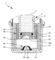
特に、本発明は、流体を噴霧するためのネブライザと、好ましくは、特に、圧壊可能バッグ、移動可能流体ピストン、又は圧縮性内腔又は内腔を形成する内側容器を含むいずれかの他の構成によって形成又は制限された可変、圧壊可能、又は圧縮性の容積の中に流体を収容する薬剤容器とに関する。[1つのタイプの実施形態では、容器は、内側容器(これは、可撓性/圧壊可能であり、好ましくは、圧壊可能バッグ又はホイル構成などの形態にある)と、ケーシングのような周囲のより剛性の構造とを含み、もう1つのタイプの実施形態では、容器は、剛性構造又はケーシングと、液体のための可変又は圧壊可能容積を形成するためにケーシング内で移動可能な流体ピストンとを含む。] In particular, the present invention relates to a nebulizer for nebulizing a fluid and, preferably, a drug container that contains the fluid in a variable, collapsible, or compressible volume, formed or limited by, among other things, a collapsible bag, a movable fluid piston, or any other configuration that includes an inner container forming a compressible lumen or lumen. [In one type of embodiment, the container includes an inner container (which is flexible/collapseable, preferably in the form of a collapsible bag or foil configuration, etc.) and a surrounding more rigid structure, such as a casing, and in another type of embodiment, the container includes a rigid structure or casing and a fluid piston that is movable within the casing to form a variable or collapsible volume for the liquid.]
好ましくは、ネブライザは、容器を挿入するために切り離す又は開口することができるハウジング部分を含む。ネブライザは、容器から流体(特に計量用量の流体)を引き出すための及び/又は流体の用量を特に流体を加圧するための推進剤を使用することなく分配するための流体ポンプ又は圧力発生器を含む。特に、容器は、多様な用量の流体を収容する。 Preferably, the nebulizer includes a housing portion that can be separated or opened for inserting the container. The nebulizer includes a fluid pump or pressure generator for drawing fluid (particularly a metered dose of the fluid) from the container and/or for dispensing a dose of the fluid, particularly without the use of a propellant to pressurize the fluid. In particular, the container contains multiple doses of the fluid.
本発明の追加の態様により、ネブライザ又はその容器は、好ましくは、容器から流体を用量単位で引き出すのを支援するために容器内の流体を加圧するための空気ポンプを含む。好ましくは、特にネブライザ又は空気ポンプが供給する又は発生させる圧力パルスは、ネブライザの引張及び/又は容器からの流体の引き出しの開始時及び/又は最中に可変容積又は容器内の流体に対して作用する。 According to an additional aspect of the invention, the nebulizer or its container preferably includes an air pump for pressurizing the fluid in the container to assist in drawing the fluid from the container in doses. Preferably, the pressure pulses provided or generated by the nebulizer or air pump act on a variable volume or fluid in the container at the initiation and/or during the pulling of the nebulizer and/or the drawing of the fluid from the container.
特に粘性流体では、容器のこの加圧は、せん断力が最終的に流体に影響を与えるノズルに流体が到達するようにネブライザ内に流体を拡散させるのを支援する。 Especially with viscous fluids, this pressurization of the container helps to spread the fluid within the nebulizer so that it reaches the nozzle where shear forces ultimately act on the fluid.
好ましくは、空気ポンプは、容器及び/又は容器内の流体を一時的にのみ、特に、ネブライザがコック、引張、又は装填される(すなわち、液体の用量を噴霧するための準備が行われる)時及び/又は液体が容器から引き出される時にのみ加圧する。すなわち、容器からの流体のいずれの望ましくない漏出も防止される又は少なくとも最小にすることができ、及び/又は容器とネブライザの流体ポンプ又は圧力発生器との間のいずれの(追加の)弁も回避することができる。これは、単純構成を可能にする。 Preferably, the air pump pressurizes the container and/or the fluid therein only temporarily, in particular when the nebulizer is tapped, pulled or loaded (i.e. prepared to spray a dose of liquid) and/or when liquid is drawn from the container. That is, any undesired leakage of fluid from the container can be prevented or at least minimized, and/or any (additional) valve between the container and the fluid pump or pressure generator of the nebulizer can be avoided. This allows for a simple construction.
更に、容器内の流体の一時的加圧は、流体/容器内のいずれのガスバブルの形成又は成長も防止することができる。これは、正確な計量をサポートし、及び/又は容器に最初に与えられる流体の全容積の最小化又は低減を可能にする。 Furthermore, temporary pressurization of the fluid within the container can prevent the formation or growth of any gas bubbles within the fluid/container. This supports accurate metering and/or allows for minimization or reduction of the total volume of fluid initially dispensed into the container.
好ましくは、空気ポンプは、容器から流体を用量単位で引き出すのを支援するために容器内の空気を一時的に加圧するためのピストン/シリンダ配置を含む又は形成する。これは、空気ポンプの非常に単純な構成を可能にする。 Preferably, the air pump includes or forms a piston/cylinder arrangement for temporarily pressurizing the air in the container to assist in drawing the fluid from the container in doses. This allows for a very simple construction of the air pump.
任意的に、ネブライザ又は空気ポンプは、容器内に空気をポンピングするために容器によって駆動されるポンプピストンを含む。これは、非常に単純な構成及び/又は公知の容器の使用を可能にする。 Optionally, the nebulizer or air pump includes a pump piston driven by the container to pump air into the container. This allows for a very simple construction and/or use of known containers.
代替実施形態により、容器は、容器の中に空気をポンピングするための空気ポンプのポンプピストンを形成することができる。これは、非常に単純な構成を可能にする。 According to an alternative embodiment, the container can form the pump piston of an air pump for pumping air into the container. This allows for a very simple construction.
好ましくは、ポンプピストンは、ネブライザのハウジング部分と協働し、又はハウジング部分に結合された又はそれによって保持されたシリンダ又はインサートと協働する。これは、非常に単純な構成を可能にし、かつ公知のネブライザの軽微な改造を必要とするのみである。 Preferably, the pump piston cooperates with a housing part of the nebulizer or with a cylinder or insert connected to or held by the housing part. This allows for a very simple construction and requires only minor adaptations of known nebulizers.
好ましくは、空気ポンプは、容器を挿入する又は置換するために切り離す又は開くことができるネブライザのハウジング部分に配置され、そこに締結され、又はそれによって形成される。 Preferably, the air pump is disposed in, fastened to, or formed by a portion of the housing of the nebulizer that can be disconnected or opened to insert or replace the container.
任意的に、容器は、ネブライザを引張、コック、装填する、又は容器から流体の用量を引き出す最中に及び/又は流体の用量を噴霧又は分配する最中に空気ポンプに対して移動可能である。この相対容器移動は、空気ポンプを作動させるために、及び/又は容器内の流体を一時的にのみ加圧する及び/又は空気ポンプを容器に一時的にのみ接続する(好ましくは、空気ポンプは、ネブライザの非引張又は非装填状態では容器に接続されない)ために好ましくは使用される。これは、非常に単純かつ確実な構成を可能にする。 Optionally, the container is movable relative to the air pump during tensioning, cocking, loading the nebulizer or drawing a dose of fluid from the container and/or during spraying or dispensing a dose of fluid. This relative container movement is preferably used to operate the air pump and/or to only temporarily pressurize the fluid in the container and/or to only temporarily connect the air pump to the container (preferably the air pump is not connected to the container in the untensioned or unloaded state of the nebulizer). This allows for a very simple and reliable construction.
任意的に、空気ポンプは、好ましくは容器の出口の反対側に及び/又は容器の通気孔を通じて容器の底部又は軸線方向端部に流体的に接続可能である。これは、非常に単純な構成又は公知のネブライザへの一体化を可能にする。 Optionally, an air pump can be fluidly connected to the bottom or axial end of the container, preferably opposite the outlet of the container and/or through a vent in the container. This allows for a very simple construction or integration into known nebulizers.
好ましくは、ネブライザ又は空気ポンプは、流体による容器の充填レベルとは関係なく周囲圧を上回る最大値へと容器内の流体に対して作用する空気圧を制限する制御弁を含む。これは、流体の正確な計量をサポート又は可能にし、及び/又は非常に高い圧力が流体に対して作用する場合に発生する可能性がある流体のいずれの望ましくない漏出も防止する。 Preferably, the nebulizer or air pump includes a control valve that limits the air pressure acting on the fluid in the container to a maximum value above ambient pressure regardless of the fill level of the container with fluid. This supports or enables accurate metering of the fluid and/or prevents any undesired leakage of the fluid that may occur if very high pressures act on the fluid.
好ましくは、ネブライザ又は空気ポンプは、空気ポンプ又はそのポンプチャンバ内のいずれの圧力不足も防止する入口弁を含む。これは、正確な計量をサポートし、噴霧中に容器内の流体に対して作用するいずれの負の力も防止することができる。 Preferably, the nebulizer or air pump includes an inlet valve that prevents any underpressure in the air pump or its pump chamber. This can support accurate metering and prevent any negative forces acting on the fluid in the container during nebulization.
好ましくは、制御弁及び入口弁は、同じ弁又は弁要素によって形成される。これは、非常に単純な構成を可能にする。 Preferably, the control valve and the inlet valve are formed by the same valve or valve element. This allows for a very simple construction.
本発明の別の態様(これは、前述の態様とは別個に又はそれらと組み合わせで検討することができる)により、少なくとも2つの成分から作り出された流体、特にリポソーム流体を噴霧するための方法が提供され、流体は、カートリッジとネブライザとのシステムから/を用いて噴霧され、カートリッジは、それ自体をネブライザに流体接続するためのポートを含み、更に少なくとも2つの成分のうちの1つを各々が収容する少なくとも2つのチャンバ/内側容積を含む。貯蔵状況では/カートリッジとの併用に向けてネブライザを準備する前に(特に、カートリッジとネブライザとを流体接続する前に)、少なくとも2つのチャンバは流体分離されている。特に、第1のチャンバは、脂質又は脂質を含む粉末を含有する好ましくはエタノール性の溶液を第1の成分として収容し、第2のチャンバは水性液体を第2の成分として収容し、これら2つの成分を組み合わせる/混合することによってリポソームを含有する生成物が作製/生成される。本発明の更に別の利点、特徴、特性、及び態様は、特許請求の範囲及び図面を参照する好ましい実施形態の以下の説明から明らかになるであろう。 According to another aspect of the invention (which may be considered separately or in combination with the previous aspect), a method is provided for nebulizing a fluid, in particular a liposome fluid, made up of at least two components, the fluid being nebulized from/with a cartridge and nebulizer system, the cartridge including a port for fluidly connecting it to the nebulizer and further including at least two chambers/internal volumes each housing one of the at least two components. In a storage situation/before preparing the nebulizer for use with the cartridge (in particular before fluidly connecting the cartridge and the nebulizer), the at least two chambers are fluidically separated. In particular, the first chamber contains a preferably ethanolic solution containing lipids or lipid-containing powder as a first component, and the second chamber contains an aqueous liquid as a second component, by combining/mixing these two components a product containing liposomes is made/produced. Further advantages, features, properties and aspects of the invention will become apparent from the following description of preferred embodiments with reference to the claims and drawings.
これらの図では、同一又は類似の部分に対して同じ参照番号を使用し、好ましくは、関連の説明を繰り返さない場合であっても対応する又は同等の特質及び利点をもたらす。 In these figures, the same reference numbers are used for identical or similar parts, preferably with corresponding or equivalent features and advantages, even if the relevant description is not repeated.
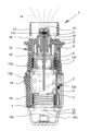
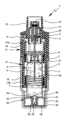
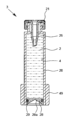
図1及び図2は、特に水性液体、特に高度に有効な医薬組成物又は薬剤などを霧化するための公知のネブライザ1を非引張状態(図1)及び引張状態(図2)で示している。ネブライザ1は、特に可搬吸入器として構成され、かつ好ましくは機械的にのみ及び/又は推進剤を用いずに動作する。
Figures 1 and 2 show a
本発明により、驚くべきことにこのネブライザは、従来の低粘性液体又は特に水溶液を噴霧するためだけではなく、多種多様な流体2、特に、液相(少なくともつの液相)を含み、1.6センチポアズまでの基準粘性又はせん断速度依存性に起因して1.6又はそれを下回るセンチポアズまで低減することができる粘性を有する流体2を噴霧するためにも使用することができる。
The present invention surprisingly allows that the nebulizer can be used not only for nebulizing conventional low-viscosity liquids or especially aqueous solutions, but also for nebulizing a wide variety of
流体2、より具体的には医薬組成物が噴霧されると、エアロゾル14(図1)が形成又は分配され、それをユーザが吸息又は吸入することができる。通常、吸入は、患者が患っている病気又は疾患に依存して1日に少なくとも1回、より具体的には1日に数回、好ましくは、設定された間隔で行われる。
When the
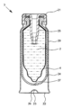
ネブライザ1には、流体2を収容する挿入可能又は交換可能容器3が設けられるか、又はネブライザ1はそれを含む。従って、容器3は、噴霧される流体2に対するリザーバを形成する。
The
図1及び図2には容器3を概略的にしか示しておらず、図4の断面図により詳細に示している。
The
容器3は、好ましくは本質的に円筒形又はカートリッジ形であり、ネブライザ1が開けられると、容器3をその中に好ましくは下方から挿入し、必要に応じて入れ替えることができる。
The
好ましくは、容器3は、特に、例えば少なくとも100又は150、及び/又は200まで又はそれよりも多い投与単位又は用量を提供するのに十分であり、すなわち、少なくとも100回及び/又は200回までのスプレー又は投与を可能にするのに十分な流体2又は多様な用量の活性物質を収容する。容器3は、好ましくは、約0.5mlから30mlまで、好ましくは2mlから20mlまでの容積を保持する。
Preferably, the
更に、容器3に収容される用量及び/又は容器3に収容される流体2の全容積は、流体2又はそれぞれの薬剤に基づいて、容器3に基づいて、及び/又は必要な投薬などに基づいて異なる場合がある。
Furthermore, the dose contained in the
好ましくは、ネブライザ1は、ネブライザ1の1回作動/使用内で/1回スプレー/エアロゾル送出/分配内で1マイクロリットルから80マイクロリットルの流体2の用量、更に好ましくは、5マイクロリットルよりも多く、10マイクロリットル、又は20マイクロリットル、又は約50マイクロリットルの用量を噴霧するようになっている。
Preferably, the
好ましくは、同じネブライザ1で使用することができるネブライザ1の総使用回数は制限される。従って、容器3を交換する又は置き換えることができる場合に(ネブライザ1又は容器3を保持するためにネブライザ1内にあるホルダ6は、容器3を解除する又は置き換えることができるように構成される)、同じネブライザで使用することができる容器3の個数は、例えば、合計で3個、4個、5個、又は6個に制限される。そのような制限についての詳細は、複数の容器を用いる連続使用に向けたネブライザを開示している国際公開第2012/162305号に示されており、このネブライザは、それと併用されることになる容器の総個数を制限するための機構を含む。
Preferably, the total number of uses of the
好ましくは、ネブライザは、ある一定の作動回数又は動作回数又は放出用量に達した又はそれを超えた時に更に別の使用を防ぐようにネブライザをロックするロックデバイス126を含む。特に、比較的大きい容器3と併用される場合には、作動回数又は動作回数は、1つの容器3から分配されることになる用量に対応する。
Preferably, the nebulizer includes a
ネブライザ1は、特に事前設定されて任意的に調節可能な投与量で流体2を搬送又は噴霧するための流体ポンプ5(これは、圧力発生器、すなわちネブライザ1の送出機構の一部である)を含む。特に、流体ポンプ5は、好ましくは、ネブライザ1をコック、引張、又は装填する時に流体2、すなわち、その用量を容器3又はそのバッグ/容積4から引き出す又は吸引する。次いで、好ましくは、引張過程又は装填過程の後の第2の段階では、引き出された液体2又はその用量が分配、特に加圧及び/又は噴霧される。特に、ネブライザ1は、装填過程又は引張過程中に装填される(好ましくは引張される)エネルギストア(好ましくは、駆動バネ7)を含み、このエネルギは、引張過程又は装填過程中にネブライザ1内に引き込まれた流体2又はその用量を噴霧するために解放される。従って、好ましいネブライザ1の通常使用は、装填過程と分配過程を包含する。
The
ネブライザ1又は圧力発生器/流体ポンプ5は、好ましくは、容器3を保持するためのホルダ6、それに結合された部分的にしか示していない駆動バネ7、及び/又は好ましくは手動の作動又は押下に向けてボタン8bの形態にある又はそれを有する阻止要素8を含む。阻止要素8は、ホルダ6を捕捉して阻止し、ホルダ6を解除して駆動バネ7が拡張することを可能にするように手動で動作させることができる。
The
ネブライザ1又は圧力発生器/流体ポンプ5は、好ましくは、搬送チューブ9のような搬送要素、逆止弁10、圧力チャンバ11、及び/又は流体2をマウスピース13内に噴霧するためのノズル12を含む。
The
完全に挿入された容器3は、搬送要素が容器3又はそのバッグ4をネブライザ1又は圧力発生器/流体ポンプ5に流体的に接続するようにホルダ6を通じてネブライザ1内に固定又は保持される。好ましくは、搬送チューブ9は、容器3及び/又はバッグ/容積4の中に貫通する。
The fully inserted
駆動バネ7が引張過程で又はコック中に軸線方向に引張されると、ホルダ6は、容器3及び搬送チューブ9と共に図面内の下方に移動され、流体2は、容器3から流体ポンプ5又はその圧力チャンバ11内に逆止弁10を通して取り込まれる又は吸い込まれる。この状態では、ホルダ6は、駆動バネ7が圧縮状態に保たれるように阻止要素8によって捕捉される。この時に、ネブライザ1はコック状態又は引張状態にある。
When the
阻止要素8の作動又は押下(直接的か又は付属のボタン8bを押下するかのいずれかによる)の後の噴霧過程でのその後の緩和中に、この時点では閉鎖している逆止弁10を有する搬送要素9がこの時点では押圧ラム又はピストンとして作用する駆動バネ7の緩和又は力によって圧力チャンバ11内でこの場合に図面内の上方に後退する時に、圧力チャンバ内11の流体2は、圧力下に置かれる。この圧力は、ノズル12を通して流体2を押圧し、この時に、流体2は、図1に示すようにエアロゾル14に霧化され、従って、分配される。
During the subsequent relaxation in the spraying process after activation or depression of the blocking element 8 (either directly or by pressing the associated
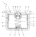
ノズル12は、好ましくはマイクロ構造化構成要素によって形成される。吸入可能エアロゾルを生成するために、ほとんどのネブライザ設計は、多くの場合に半導体作製からのリソグラフィ製造法、放電加工技法、又はレーザ穴あけ技法のようないわゆるマイクロシステム技術によって生成される極小ノズル構造を必要とする。
The
特定の実施形態において挿入に用いることができるマイクロ構造化構成要素又はノズル12を図3に示している。図示のノズル12は、好ましくはシリコンのマイクロ構造化プレート12aと、これらの構造を覆う好ましくはガラスで作られたカバープレート12bとで構成される。図示の実施形態では、ネブライザを用いた流体の噴霧は、好ましくは2つの流体噴流の高速衝突に基づき、すなわち、流体噴流は、好ましくは2つのノズルチャネル12dから又は付属のノズル開口部12eから射出し、所定の角度で出会うように導かれ、衝突中に作用する力によって噴霧される。
A microstructured component or
好ましくは、ネブライザ1は、ノズル開口部12eを閉塞のない状態に保ち、それによってノズル12の動作能力を確実にするためにノズル開口部12eの上流で粒子を濾過して除去するための手段を含む。
Preferably, the
最も好ましくは、マイクロ構造化構成要素又はノズル12は、ノズル開口部12eと微細濾過フィルタ12fとの両方を含む。図示の実施形態では、ノズル12は、(流体の流れ方向に沿って見た場合に)入口開口部12g、それに続く流入領域12c、流れ方向に沿う流れフィルタとして設計された微細濾過フィルタ12f、更にノズルチャネル12d(これはノズル開口部を形成する)を形成するマイクロ構造を含む。フィルタ作用は、固体ストラット及び通路の特殊配置によって達成される。特に好ましいのは、製造された四角形断面を有する微細通路の列のジグザグ配置である。好ましくは、通路の幅は、ノズル開口部12eの幅よりも小さい。
Most preferably, the microstructured component or
図示の実施形態では、好ましいマイクロ構造化構成要素12のノズルチャネル12dの寸法はわずか数ミクロンである。好ましくは、ノズルチャネル12dは、3ミクロンから20ミクロンまで、特に4ミクロンから12ミクロンまで、最も好ましくは5ミクロンから8ミクロンまでの辺長(水力直径に対する類似の値に対応する)を有する四角形断面を有する。ノズルチャネルの寸法決定は、多くの場合に、ある一定の時間枠内で吐出すべき用量容積に依存する。1用量内及び2sよりも短いスプレー時間以内に50μlの容積を噴霧するためには、作動毎の搬送/送出容積をそのように調節する以外に、ノズルチャネル12dの幅及び高さを11~12ミクロンへと拡大するのが適切である。一般的に(図1から図3に記載のネブライザに注目すると)、1つの噴霧容積(例えば15μlの)から別の噴霧容積(例えば50μmの)へとネブライザ1の設定を変更するのは、ノズル出口径の寸法、バネ7の力、及び圧力チャンバ11及びその中を移動するピストン(この実施形態では搬送チューブ9によって形成される)の断面積を調節するだけでよい。
In the illustrated embodiment, the dimensions of the
それに応じて、微細濾過フィルタ12fの通路の幅もわずか数ミクロンであり、好ましくは、サイズが約2ミクロンまでの粒子は、ノズルチャネル12dに進入し、その後、噴霧の後に吸入器のユーザによって吸息される前に流体から取り除かれる。好ましくは、ノズルチャネル12dは、10ミクロンから100ミクロンまで、特に20ミクロンから60ミクロンまで、最も好ましくは30ミクロンから50ミクロンまでの長さを有する。好ましくは、ノズル寸法は、噴霧すべき流体に適合するように選ばれる。すなわち、短めのチャネル長では流速が増大し、小さめの直径では、流体自体に起因するチャネル閉塞のリスクが高まる恐れがある(特に例えば懸濁液では)。
Correspondingly, the width of the passages of the
マイクロ構造化構成要素又はノズル12に対して、又はノズルアセンブリ内に設置された微細濾過フィルタ12fに対して考えられる構造の更に別の詳細は、国際公開第94/07607号、国際公開第99/16530号、国際公開第05/000476号、国際公開第07/101557号、及び国際公開第08/138936号の明細書に開示されている。
Further details of possible structures for the microstructured component or
好ましくは、ネブライザは、ノズル又はそれを形成するマイクロ構造化構成要素に流体2が進入する前にそれを濾過するフィルタシステム又は前置フィルタ11bを含む。好ましくは、フィルタシステム又は前置フィルタ11fは、圧力チャンバ11の流体出口領域内に配置される。好ましくは、前置フィルタ11f又はそのフィルタシステムを形成する個々のフィルタ構成要素のフィルタ閾値は、各フィルタが、サイズ除外原理に従って当該フィルタの前のフィルタよりも小さい粒子を通すようなサイズのものである。
Preferably, the nebulizer comprises a filter system or pre-filter 11b that filters the
図示の実施形態では、前置フィルタは、ノズルチャネル12dの水力直径よりも若干大きいサイズの濾過閾値、例えばノズルチャネル12dに対する6~7ミクロンの水力直径の場合には10ミクロンの閾値を好ましくは有する(すなわち、このフィルタは、10マイクロメートルよりも大きい粒子を食い止める)。好ましくは、フィルタは、流体2又はその含有物と化学反応しない材料からなる。特に、フィルタは、ポリオレフィン、好ましくはポリエチレン(PE)又はポリプロピレン(PP)、最も好ましくはその焼結形態にあるものからなる。
In the illustrated embodiment, the pre-filter preferably has a filtering threshold slightly larger than the hydraulic diameter of the
逐次高まる分離レベル又は逐次小さくなる細孔サイズを有するフィルタ配置により、全体的に高めのフィルタ性能、すなわち、フィルタの完全な目詰まりを伴わないより多量の粒子又はその凝塊の付着、及びより完全な濾過が達成される。チャネル内に設置され、最も大きい細孔径を有する第1のフィルタは、大きい粒子又はその凝塊のみを捕集し、小さめの細孔径を有する次のフィルタは小さめの粒子を捕集し、以降同様に続く(マイクロ構造化構成要素の微細濾過フィルタ12f内の通路は濾過構成要素の配列内で最も小さい細孔径を形成する)。送達される流体又は液体の所要の粒子負荷又は粒子の非含有度に依存して、更に別の濾過構成要素を組み込むこともできる。このようにして、微細孔フィルタは、いずれの流体又は液体が通り抜けることも全く許すことができない点まで大きい粒子を直接目詰まりさせることはない。ネブライザ内で考えられる濾過構成要素配列の更に別の詳細は、国際公開第2012/007315号の明細書に開示されている。
A filter arrangement with successively higher separation levels or successively smaller pore sizes achieves an overall higher filter performance, i.e., a higher amount of particles or agglomerates without complete clogging of the filter, and more complete filtration. The first filter installed in the channel and having the largest pore size will only collect the larger particles or agglomerates, the next filter with a smaller pore size will collect the smaller particles, and so on (the passage in the
流体2が固体粒子の懸濁液、例えばナノ懸濁液である場合には、粒子は、ネブライザの全てのフィルタを通過するように好ましくは設計される、すなわち、粒子は、微細濾過フィルタ12fの通路よりも小さい直径を好ましくは有する。好ましくは、粒子は、5ミクロンよりも小さい水力直径を有する(少なくとも粒子の大部分に関して)。最も好ましくは、粒子は、微細濾過フィルタ12fの通路の幅(例えば2ミクロン又はそれよりも小さい直径)よりも小さい主断面を有し、最も大きい断面直径は、微細濾過フィルタ12fの通路の高さ(例えば8ミクロン又はそれよりも小さい)よりも小さい。更に一層好ましくは、懸濁液中の粒子はナノ粒子である。
If the
好ましくは、粒子は、集合体を形成することへの弱い傾向しか持たない(さもなければ反復作動におけるネブライザの再使用性は、フィルタ性能の急激な消耗に起因して低減されることになる)。一般的に、凝塊形成への傾向は、ナノ粒子の濃度と共に高まる。従って、懸濁粒子の濃度と共にフィルタ段の寸法決定及びフィルタ性能の重要性が高まる。 Preferably, the particles have only a weak tendency to form aggregates (otherwise the reusability of the nebulizer in repeated operations would be reduced due to rapid wear in filter performance). In general, the tendency to agglomerate increases with nanoparticle concentration. Thus, the importance of filter stage sizing and filter performance increases with the concentration of suspended particles.
凝塊を形成することへの傾向を弱める1つの可能性は、流体2への分散助剤/界面活性剤/湿潤剤の添加であり(すなわち、好ましくは、流体2は、ナノ粒子に加えて分散助剤を含む)、特に、分散粒子は、分散助剤によって(高度に)湿潤される。例えば、そのような分散助剤に起因して、分散粒子の周囲に溶媒和殻が形成され、隣接する粒子同士の間の距離が確保される。そのような溶媒和殻内に包まれたイオンは、更に電気斥力を生じる。分散助剤を用いた粒子の湿潤を促進するためにテンシドを使用することができる、すなわち、好ましくは、流体2は、分散助剤に加えて少なくとも1つのテンシドを含有する。 One possibility to reduce the tendency to form agglomerates is the addition of a dispersing agent/surfactant/wetting agent to fluid 2 (i.e. preferably fluid 2 contains a dispersing agent in addition to the nanoparticles), in particular the dispersed particles are (highly) wetted by the dispersing agent. For example, due to such a dispersing agent a solvation shell is formed around the dispersed particles, ensuring the distance between adjacent particles. Ions enclosed within such a solvation shell further create electrical repulsion. Tensides can be used to promote wetting of the particles with the dispersing agent, i.e. preferably fluid 2 contains at least one tenside in addition to the dispersing agent.
多くの場合、粒子の表面は、負の非溶媒和イオンの吸着に起因して負に帯電される。この負の電荷は、隣接する負の荷電粒子を跳ね返す。表面電荷を相殺するために、例えばペプタイザーの形態にあるイオン(例えば、クエン酸塩、酒石酸塩のような多価アニオン)を添加することができる。表面電荷は、ゼータ電位測定によって決定することができる。 In many cases, the surface of the particles is negatively charged due to the adsorption of negative nonsolvated ions. This negative charge repels neighboring negatively charged particles. To counteract the surface charge, ions, for example in the form of peptizers (e.g. multivalent anions such as citrate, tartrate) can be added. The surface charge can be determined by zeta potential measurements.
流体2、特に懸濁液、乳濁液、又はリポソーム流体が低い安定性しか持たない場合に(例えば、凝塊を形成することへの傾向を分散助剤を添加することによって十分に低減することができない時)、流体2が噴霧されることになるわずか前にそれを幾つかの(安定した)成分から混合/生成することができる。そのような比較的不安定な流体2では、(図示していない)カートリッジを使用することができ、カートリッジ内では、ネブライザがこのカートリッジと併用されるわずか前に流体接続される(混合に向けて)カートリッジの様々な区画/内側容積の中に、流体2の様々な成分からなる例えば粉末が貯蔵される。そのようなカートリッジに関する例は、国際公開第97/39831号及び国際公開第00/23037号に開示されている。国際公開第97/39831号は、例えば薬物の貯蔵時間を延長するための活性成分/薬物及び薬物に対する溶媒の別個の貯蔵に向けて2つの区画を有するカートリッジを開示している。カートリッジがネブライザの中に挿入される時に、活性成分/薬物を収容する区画は、活性成分/薬物を溶媒中に溶解することができるようにカニューレ/中空針(例えば、ネブライザ1の搬送チューブ9のような要素によって形成された)によって穿通される。
In cases where the
流体2の様々な成分を別個に貯蔵し、流体2を使用するわずか前にこれらの成分を混合するというこの方式は、流体2が構造化流体である時にも有利とすることができる、すなわち、流体2の安定性は、構造化流体を形成する分散液の安定性によっても影響を受ける。
This approach of storing the various components of
特に、ネブライザとのカートリッジ(容器3、図示していない実施形態)の併用の少し前又は直前/ネブライザ1を用いて流体2をカートリッジから噴霧する前にリポソーム流体の成分同士を混合することが可能である。好ましくは、リポソーム流体又は流体2中のリポソームは、カートリッジ(容器3、図示していない実施形態)内のチャンバの内部で上記のように形成される。
In particular, it is possible to mix the components of the liposome fluid shortly or immediately before use of the cartridge (
本発明の一態様により、カートリッジ/容器3と、そこから流体2を噴霧するためのネブライザ1及びネブライザとのシステムが実現され(好ましくは、流体は、治療/医薬流体又は少なくとも1つの薬物/少なくとも1つの活性成分を含む流体である)、流体2は、少なくとも1つの成分から作られ/生成され、カートリッジは、カートリッジ/容器3をネブライザ1に流体接続するための密封栓25/ポートを含み、カートリッジ/容器3は、少なくとも2つの成分のうちの1つを各々が収容する少なくとも2つのチャンバ/内側容積を含む。貯蔵状況では/カートリッジ/容器3との併用に向けてネブライザ1の準備を整える前に/カートリッジ/容器3とネブライザ1とを流体接続する前に、少なくとも2つのチャンバは流体分離されている。特に、第1のチャンバは、脂質又はそれを含む粉末/粒子を含有する好ましくはエタノール性の溶液を第1の成分として収容し、第2のチャンバは、水性液を第2の成分として収容し、リポソーム薬剤/リポソームを含有する医薬製品が、これら2つの成分を組み合わせる/混合することによって作られる/生成される。
According to one aspect of the present invention, a system of a cartridge/
好ましくは(この混合方式において)、流体2を形成するために混合される少なくとも2つの成分のうちの少なくとも1つは、貯蔵中に好ましくは粉末及び/又は特に好ましくはフリーズドライ又は凍結乾燥の粒子/リポソームの形態にある固体である。好ましくは、活性成分/薬物は、乾燥した粒子/リポソーム及び/又はリポソーム膜の中に埋め込まれる又はカプセル封入される。粉末又は粒子は、ラクトース、マンニトール、レシチン、コレステロール、ポリエチレングリコール、又はグリセリンなどのような1つ又は2つ以上の添加剤を含むことができる。
Preferably (in this mixing method), at least one of the at least two components mixed to form the
例えば、1つ又は2つ以上の親油性/疎水性の活性成分(薬物)は、リポソーム又はリポソーム膜の中に埋め込まれる又はカプセル封入される(例えば、ブデソニド、シクレソニド、フルチカゾン、又はベクロメタゾンのようなグルココルチコイド)。 For example, one or more lipophilic/hydrophobic active ingredients (drugs) are embedded or encapsulated in the liposome or liposomal membrane (e.g., glucocorticoids such as budesonide, ciclesonide, fluticasone, or beclomethasone).
少なくとも2つの別個に貯蔵された成分のうちの第2のものは流体、特に水又はそれを含有する溶媒である。(これに加えて又はこれに代えて)第2の成分は、それぞれの溶媒中への良好な可溶性を有する1つ又は2つ以上の疎油性/親水性活性成分(薬物)(例えば、活性成分は、ベータ-2-交感神経作動薬の群に属する)を含むことができる。 The second of the at least two separately stored components is a fluid, in particular water or a solvent containing it. (Additionally or alternatively) the second component may contain one or more lipophobic/hydrophilic active ingredients (drugs) having good solubility in the respective solvent (e.g., the active ingredient belongs to the group of beta-2-sympathomimetics).
一般的に、ネブライザ1は、水性流体の噴霧に向けて5MPaから250MPaまで、好ましくは10MPaから50MPaまでの圧力で動作し、ネブライザのプライミング中、すなわち、流体ポンプ5の初回の作動時に初めて流体2がネブライザ1の中(すなわち、圧力チャンバ、ノズルチャネルなどの中)で分散される時に100MPa(1000bar)(一般的に通常動作圧のサイズの約2倍)までの圧力ピークを発生させることができる。
Typically, the
非ニュートン流体2の噴霧では、比較的高い圧力範囲での動作が好ましく、すなわち、好ましくは、ネブライザ1は、10MPaから100MPaまで、最も好ましくは20MPaから50MPaまでの圧力で流体2に対して動作する。好ましくは、圧力発生のためのエネルギは、30Nから120Nまでの範囲にわたる平均力、最も好ましくは45Nから90Nまでの範囲にわたる例えば60Nの平均力を有する駆動バネ7によって与えられる。(120Nバネの使用は、1000barまでの圧力を生じることになるが、デバイスの引張のために比較的高い操作力を必要とする。)
For nebulization of
好ましくは、ストローク毎に10μlから50μl、好ましくは10μlから30μlまで、最も好ましくは約15μlの流体2の容積が送出される。
Preferably, a volume of
流体2は、エアロゾル14に変換又はエアロゾル14として噴霧され、その小滴は、20ミクロンまで、好ましくは3ミクロンから10ミクロンまでの空気動力学的直径を有する(ネブライザ1が吸入器である場合に、大部分の粒子が吸入に向けて小さめの5ミクロンである)。好ましくは、発生する噴射スプレーは、20°から160°、好ましくは、80°から100°の角度を有する。これらの値は、本発明の教示によるネブライザ1に特に好ましい値として適用される。
The
ユーザ又は患者(図示せず)は、エアロゾル14を吸入することができ、好ましくは、同時に少なくとも1つの任意的な空気供給開口部15を通して空気をマウスピース13内に吸い込むことができる。
A user or patient (not shown) can inhale the
衝突噴流霧化によって発生するエアロゾルの小滴サイズは、噴流が射出するノズルチャネル12dの直径と、噴流の速度と、表面張力(例えば水では0.072N/m)と、流体2の密度とに依存する。噴流の速度は、チャネル寸法と流体2に対して発揮される圧力とに依存する。(例えば、1.5mmの直径を有するピストン(好ましくは搬送チューブ9によって形成された)を押圧する45Nのバネ力で流体ポンプ5が発生させる圧力は、25MPa(=250bar)程度のものであり、流体2がノズルチャネル12dに到達すると20%だけ低減されて20MPa前後の値になる可能性がある。)
The droplet size of the aerosol generated by impingement jet atomization depends on the diameter of the
流体2がチャネル内を流れる時に、結果として生じる流れは、チャネルの表面上で流速がゼロであり、チャネルの中央で最大速度である流れプロファイルを有する。従って、流体2がノズルチャネル12dを通って進む時にせん断力が発生する。せん断速度は、移動する流体の隣接層同士の間の相対運動の程度又は速度の尺度として定義され、すなわち、せん断速度は、チャネル表面からの距離に関する速度勾配である。
As
最終的に、チャネルの表面から境界層が発達し、流れプロファイルは、中心における比較的平坦なプロファイルと、チャネル表面での流速の急激な減少とによって更に決定される。 Finally, a boundary layer develops from the surface of the channel and the flow profile is further determined by a relatively flat profile in the center and a rapid decrease in flow velocity at the channel surface.
本発明により、ノズルチャネル12d内で発生する速度勾配/せん断力は、非ニュートン流体又は非ニュートン液体の粘性を低減するために用いられる。好ましくは、粘性の低減は(特に1.6センチポアズを下回る粘性に至るまでの)、ノズル12を通しての流体2の分配の開始時に既に発生しており、これは、続いて流体を連続的に/発生したパフの残りの持続時間にわたって実際にスプレーすることができることによる。
According to the present invention, the velocity gradient/shear forces generated within the
粘性の低減は、以下の理論に従って説明することができる。すなわち、流体2に最初に圧力が印加されると、流体は、最初の高い粘性ηを有する。印加圧への最初の反応として単純な粘性流を仮定すると、流れは、ノズルチャネル12dを通って分配を開始する時に最初にハーゲン・ポアズイユの法則に従う挙動を示す。そのような流れは放物状流れプロファイルを有し、チャネル表面において最も高い速度勾配が発生する。この場合、速度勾配は、二噴流衝突原理に必要とされる噴流を発生させるのに適するレベルまで中心速度が急速に高まることができるように粘性を低減するのに十分に高いものとすることができる。
The reduction in viscosity can be explained according to the following theory: when pressure is first applied to the
このモデルによる計算では、(図3に記載の実施形態による四角形)ノズルチャネル12dは、水力直径dh=2db/(d+b)(dは高さであり、bはチャネルの幅であり、計算のための例証的な値は、d=5.6μm=5.6×10-6m及びb=8μm=8×10-6mである)を有する丸形チューブで置き換えられる。流れは、チューブ/ノズルチャネルの内面を力kで押圧し(チューブ内面積は、チューブ長をlとしてF=πldH/2=πrlであり、例えばl=40μmである)、すなわち、次式が成り立つ。
![]()
![]()
この式から、速度勾配を次式として導出することができる。
![]()
![]()
ここで、チューブ全長lに沿う圧力差をΔp(例えば通常動作圧として20MPa)としている。 Here, the pressure difference along the entire tube length l is Δp (for example, 20 MPa as the normal operating pressure).
チューブ内の平均速度は、容積流量V/tと断面積の比、すなわち、次式によって与えられる。
![]()
![]()
一般的に、表面での速度勾配が非ニュートン流体の粘性の適切な低減に対して十分に高くなると、流れ/噴流の速度が高まり、この高まった速度を維持することができる。 In general, once the velocity gradient at the surface becomes high enough for an appropriate reduction in the viscosity of the non-Newtonian fluid, the flow/jet will increase in velocity and be able to sustain this increased velocity.
100cP=0.1kg/(ms)の粘性を有する流体(例えば懸濁液)では、このモデルは、今述べた例証的な値に対して16×106/sの速度勾配を与える(この場合、この粘性は中程度の粘性と見なされ、比較のために、水の(低い)粘性は、この状況では1.6×109/sの勾配を生じることになり、このタイプのデバイスのせん断速度は実際に非常に高い)。スプレーするのに必要な速度増加を達成するためには、粘性のせん断依存性が、上記のような速度勾配が印加される時に大幅に減少するような形態のものでなければならない。 For a fluid (e.g., a suspension) with a viscosity of 100 cP = 0.1 kg/(ms), this model gives a velocity gradient of 16 x 106 /s for the illustrative values just mentioned (this viscosity is considered moderate in this case; for comparison, the (low) viscosity of water would produce a gradient of 1.6 x 10⁹ /s in this situation, a shear rate that is indeed very high for this type of device). In order to achieve the velocity increase required for spraying, the shear dependence of the viscosity must be of a form such that it is significantly reduced when a velocity gradient such as that described above is applied.
104cP=10kg/(ms)の初期粘性を有する乳濁液に対する同じ計算は、1.6×105/sの速度勾配を生じる。懸濁液の例の場合と同様に、この速度勾配は、この場合に必要とされる粘性の低減に十分でなければならない。ここで解説するネブライザのノズルにおいて発生するせん断速度のこの大きさは、粘性のせん断速度依存性が既知である流体に対して粘性の減少を起こすのに十分でなければならない。(ここで示す計算が、ネブライザ内で発生する過程に対して理想化された仮定に基づく場合であっても)そのようなせん断速度依存性に関してたびたび引き合いに出す例は、100cPと107cPの間の粘性で始まり、一般的にせん断速度は、10/s及びそれを下回るせん断速度で粘性に影響を与え始める(強いせん断速度依存性に関する良い例は、10-2/sで始まる線形せん断速度依存性を有する約2×106cPの粘性で始まる0.05%ポリアクリルアミド溶液である)。 The same calculation for an emulsion with an initial viscosity of 104 cP = 10 kg/(ms) would yield a velocity gradient of 1.6 x 10⁵ /s. As with the suspension example, this velocity gradient must be sufficient for the viscosity reduction required in this case. This magnitude of shear rate occurring in the nozzle of the nebulizer described here must be sufficient to cause a reduction in viscosity for a fluid with a known shear rate dependence of viscosity. An example often cited for such a shear rate dependence (even though the calculations presented here are based on idealized assumptions for the processes occurring in the nebulizer) begins with a viscosity between 100 cP and 107 cP, with the shear rate typically starting to affect the viscosity at shear rates of 10/s and below (a good example of a strong shear rate dependence is a 0.05% polyacrylamide solution that begins with a viscosity of about 2 x 10⁶ cP with a linear shear rate dependence beginning at 10-2 /s).
上述の計算は、ネブライザの通常動作圧に基づくことに注意しなければならない。好ましくは、ネブライザが流体で初めて充填される時に発生する強い圧力パルスが、せん断速度を開始するために使用され、すなわち、ネブライザを初めてプライミングする時に圧力ピークが発生する。この圧力パルスは、非ニュートン流体の場合に必要とされる粘性の低減を達成するのに必要なせん断速度の増加と同時発生することから、非ニュートン流体を噴霧することに関するシステムの適性が向上する。 It should be noted that the above calculations are based on the normal operating pressure of the nebulizer. Preferably, a strong pressure pulse that occurs when the nebulizer is initially filled with fluid is used to initiate the shear rate, i.e., a pressure peak occurs when the nebulizer is initially primed. This pressure pulse coincides with the increase in shear rate required to achieve the required reduction in viscosity for non-Newtonian fluids, thus improving the suitability of the system for nebulizing non-Newtonian fluids.
特に、ここで解説する寸法のネブライザに対する圧力パルスは、30MPa~65MPa(又は非常に強いバネでは最大で200MPa)の大きさを有する。上述した100cPの粘性を有する乳濁液の計算例では、この圧力パルスの大きさは、ここで提示する計算による高い初期速度勾配を54×106/s(1.6×108/s)程度の高さのものとすることができることを意味する。 In particular, pressure pulses for a nebulizer of the dimensions described herein have a magnitude of 30 MPa to 65 MPa (or up to 200 MPa for a very strong spring). In the example calculation given above for an emulsion with a viscosity of 100 cP, this pressure pulse magnitude means that the high initial velocity gradients calculated here can be as high as 54 x 106 /s ( 1.6 x 10⁸ /s).
初期粘性が増加すると、このモデルによる速度勾配は減少する(それに加えて、境界層厚が粘性と共に増大する)。従って、非常に高い粘性が、高いせん断速度の形成を阻止することになる、すなわち、高粘性流体は、このようなシステムを用いた噴霧を可能にするために低いせん断速度において粘性の強いせん断依存性を予め有していなければならない。しかし、上述のせん断速度計算が示すように、このポンプ-ノズル構成に対する高さ程度のせん断速度では、最終的にノズルチャネルへと流れ始めるいずれのものもせん断されることになる。 As the initial viscosity increases, the velocity gradient from this model decreases (plus boundary layer thickness increases with viscosity). Thus, very high viscosity would prevent the formation of high shear rates; i.e., highly viscous fluids must already have a strong shear dependence of viscosity at low shear rates to enable spraying with such a system. However, as the shear rate calculations above show, at shear rates of about the height for this pump-nozzle configuration, anything that does eventually begin to flow into the nozzle channel will be sheared.
図1に記載のソフトミスト吸入器/ネブライザを用いた構造化流体の噴霧に関するデータ例は以下の通りである。 Example data for spraying structured fluids using the soft mist inhaler/nebulizer described in Figure 1 is as follows:
1.「7%ブデソニド」-ナノ懸濁液のスプレー:
ブデソニドの水性ナノ懸濁液(71.079mg/mL)は、0.0075%ツイーン80及び0.0075%SDS(これら両方がテンシドであり、すなわち、ツイーン80=ポリソルベート80はo/w乳化剤であり、SDS=ラウリル硫酸ナトリウムは=/W乳化剤である)を含む1%HPC-SL(分散助剤)中で調製した。HPC-SL(ヒドロキシプロピルセルロース)は、ナノ懸濁液を安定化するために使用され、すなわち、分散助剤であり、その添加は、結果として生じる流体の粘性の増加を誘発する。このナノ懸濁液の粘性に対して、106cPという値(せん断速度依存性に関する開始値)を測定した(実験室条件、すなわち室温で)。ブデソニド粒子のサイズ低減に粉砕処理を用いた。
1. "7% Budesonide" - Nanosuspension Spray :
An aqueous nanosuspension of budesonide (71.079 mg/mL) was prepared in 1% HPC-SL (dispersing aid) containing 0.0075% Tween 80 and 0.0075% SDS (both of which are tensides, i.e. Tween 80=Polysorbate 80 is an o/w emulsifier and SDS=Sodium Lauryl Sulfate is an o/w emulsifier). HPC-SL (hydroxypropyl cellulose) is used to stabilize the nanosuspension, i.e. it is a dispersing aid, the addition of which induces an increase in the viscosity of the resulting fluid. A value of 106 cP (onset value for shear rate dependence) was measured for the viscosity of this nanosuspension (at laboratory conditions, i.e. room temperature). A milling process was used for size reduction of the budesonide particles.
懸濁液の固体粒子(噴霧後の)の典型的なゼータサイザ測定のグラフは、約132nmの半径サイズで46nmのピーク幅のピークをなす粒子サイズの安定した単峰性分布を示す(これらの粒子は、噴霧の前にも類似のサイズ分布を示した)。 A typical Zetasizer measurement graph of the solid particles of the suspension (after atomization) shows a stable monomodal distribution of particle sizes peaking at a radial size of approximately 132 nm and a peak width of 46 nm (these particles had a similar size distribution before atomization).
「7%」のブデソニド水中懸濁液を用いた実験は、ネブライザ1/図1~図4に記載のネブライザ1/ソフトミスト吸入器(試験構成:バネ力45N、8μmの幅と5.6μmの高さとを有するノズルチャネル)を用いて懸濁液を再現可能に噴霧することができることを示した。すなわち、実用試験(1日当たりの平均作動回数で2回の作動を行う)は、被験ネブライザが、実験を行った3ヶ月にわたって一定の懸濁液容積を分配することを示した。ネブライザの初期充填は、容器からの流体の引き出し中に流体の補助加圧を行うことなく可能であり(補助加圧の選択は、更に高い粘性の流体の噴霧に特に好ましく、これについては後に解説する)、被験システムのほとんどは、最初の作動時でさえも何らかのエアロゾル発生を示し、7%ブデソニドナノ懸濁液を用いて試験した全てのネブライザに関してプライミングは無難であった(この種のシステムでは、水性液体を噴霧する時であっても、完全な一用量の吐出には、通常は数回の作動が必要である)。
Experiments with a "7%" budesonide suspension in water showed that the suspension could be reproducibly nebulized using the
驚くべきことに、噴霧される懸濁液の微粒子分量は、類似のネブライザ(噴霧は、二噴流衝突原理に従って発生する)を用いて噴霧された従来の水溶液に関する分量さえも上回る。すなわち、カスケード衝突器(次世代型衝突器、略してNGI)を用いたデータ測定は、60%の範囲内の微粒子分量(5ミクロン及びそれよりも小さい直径を有するエアロゾル粒子の分量)を示した。懸濁液中に存在するナノ粒子及び/又は添加剤の種類及び濃度に依存して更に高い微粒子分量が達成可能であるように思われる。 Surprisingly, the fine particle fraction of the nebulized suspension exceeds even that for conventional aqueous solutions nebulized using a similar nebulizer (nebulization occurs according to the two-jet collision principle): data measurements using a cascade impactor (Next Generation Impactor, abbreviated NGI) showed fine particle fractions (fraction of aerosol particles with a diameter of 5 microns and smaller) in the range of 60%. Even higher fine particle fractions appear to be achievable depending on the type and concentration of nanoparticles and/or additives present in the suspension.
これに関して考えられる説明は、スプレーを発生させる噴流が液膜を形成するのに必要とされる流速を獲得すると、流体の表面張力が、この膜を離れるエアロゾル小滴の形成に関する適切なパラメータであることである。おそらく、ナノ懸濁液に対する表面張力は低減され(従来の水溶液(医療製剤)の表面張力と比較して)、すなわち、固体粒子が存在する場合には流体表面がより簡単に崩壊する。 A possible explanation for this is that once the jet generating the spray acquires the flow velocity required to form a liquid film, the surface tension of the fluid is the relevant parameter for the formation of aerosol droplets leaving this film. Presumably, the surface tension for nanosuspensions is reduced (compared to that of conventional aqueous solutions (medical preparations)), i.e. the fluid surface breaks down more easily in the presence of solid particles.
2.水中油乳濁液のスプレー:
水中に0.1%シクロスポリンを含む市販で入手可能な乳濁液(水と、シクロスポリンと、グリセリンと、セタルコニウムクロリドと、中鎖トリグリセリド(MCT)と、水酸化ナトリウムと、ポロクサマー188と、チロキサポールとを含む重度角膜炎の治療に向けた点眼液であるIkervis(登録商標))を図1~図4に記載のソフトミスト吸入器(試験構成:バネ力60N、8μmの幅と5.6μmの高さとを有するノズルチャネル)を用いて成功裏に噴霧した。この場合、驚くべきことに、噴霧される懸濁液の微粒子分量は、類似のネブライザ(噴霧が二噴流衝突原理に従って発生する)を用いて噴霧された従来の水溶液に関する分量さえも上回る。すなわち、レーザ回折技法によるデータ測定は、75%の範囲内の微粒子分量(5ミクロン及びそれよりも小さい直径を有するエアロゾル粒子の分量)と1.6sのスプレー時間とを示した。(眼科投与では、小さい吸入可能分量しか取得しないようにバネ力及びノズル径を寸法変更しなければならず、この構成における測定は、水中油乳濁液を用いてスプレーを発生させるためのシステムの能力を証明するためだけのものであった。)
2. Oil-in-water emulsion spray :
A commercially available emulsion containing 0.1% cyclosporine in water (Ikervis® eye drop for the treatment of severe keratitis containing water, cyclosporine, glycerin, cetalkonium chloride, medium chain triglycerides (MCT), sodium hydroxide, poloxamer 188 and tyloxapol) was successfully nebulized using the soft mist inhaler described in Figures 1 to 4 (test configuration: spring force 60 N, nozzle channel with a width of 8 μm and a height of 5.6 μm). In this case, surprisingly, the fine particle fraction of the nebulized suspension exceeds even that for a conventional aqueous solution nebulized using a similar nebulizer (nebulization occurs according to the two-jet collision principle). Data measurements by laser diffraction technique showed a fine particle fraction (fraction of aerosol particles with a diameter of 5 microns and smaller) in the range of 75% and a spray time of 1.6 s. (For ophthalmic administration, the spring force and nozzle diameter had to be dimensioned to obtain only a small respirable dose, and measurements in this configuration were only to prove the ability of the system to generate a spray with an oil-in-water emulsion.)
粘性のせん断速度依存性測定は、87.7センチポアズの開始粘性(すなわち室温の「静止」粘性)が4s-1のせん断速度でも既に1センチポアズまで急速に低減されてしまうこと、すなわち、小さい印加圧であっても既に製剤の粘性を水の粘性まで成功裏に低減してしまう(いわゆる「サール型」、すなわち、回転する内側シリンダを含む同心シリンダ粘度計を用いて測定して)ことを明らかにした。ネブライザの初期充填は、容器からの流体の引き出し中に流体の補助加圧を行うことなく可能であり、すなわち、最初のコック過程又は最初の引張過程の間に搬送チューブ9(これは、圧力チャンバ11内に更に加圧ラムを形成している)が圧力チャンバ11から部分的に出された時に圧力チャンバ11内に作り出される圧力不足は、容器3から流体ポンプ5又はその圧力チャンバ11の中へのこの流体2(すなわちこの乳濁液)の引き出しに対して十分である。すなわち、被験システムは、最初の作動時に何らかのエアロゾル発生を示し、すなわち、この乳濁液を用いたシステムのプライミングは良好である/わずか数回の作動で完了することができる。
Measurements of the shear rate dependence of the viscosity revealed that the starting viscosity of 87.7 centipoise (i.e. the "rest" viscosity at room temperature) is already rapidly reduced to 1 centipoise even at a shear rate of 4 s -1 , i.e. even a small applied pressure successfully reduces the viscosity of the formulation to that of water (measured using a so-called "Searle type", i.e. a concentric cylinder viscometer with a rotating inner cylinder). The initial filling of the nebulizer is possible without auxiliary pressurization of the fluid during withdrawal of the fluid from the container, i.e. the pressure deficit created in the
3.ゲルのスプレー
水性連続相中にゲル化剤を含有するゲル
水性連続相中にゲル化剤として0.5%アミロペクチン(コーンスターチ由来の)を含有するゲルを、100mlの冷水中に0.5gのスターチを分散させ、それを撹拌しながら60~70℃まで加熱することによって調製した。このゲルを図1~図4に記載のネブライザ1/ソフトミスト吸入器(試験構成:バネ力45N、8μmの幅と5.6μmの高さとを有するノズルチャネル)を用いて成功裏に噴霧した。この場合、レーザ回折技法によるデータ測定は、70%の範囲内の微粒子分量(5ミクロン及びそれよりも小さい直径を有するエアロゾル粒子の分量)と1.25sのスプレー時間とを示した。
3. Gel spray
Gels containing a gelling agent in the aqueous continuous phase
A gel containing 0.5% amylopectin (from corn starch) as gelling agent in the aqueous continuous phase was prepared by dispersing 0.5 g starch in 100 ml cold water and heating it to 60-70° C. under stirring. This gel was successfully nebulized using the
水性連続相中にゲル化剤として1.7%アミロペクチンを含有する同様に調製したゲルでさえも、ゲル化剤の濃度の増加が少なめの微粒子分量と長めのスプレー時間とを生じたものの、図1~図4に記載のネブライザ1(試験構成:バネ力45N、8μmの幅と5.6μmの高さとを有するノズルチャネル)を用いて成功裏に噴霧された。この場合、レーザ回折技法によるデータ測定は、45%の範囲内の微粒子分量と1.4sのスプレー時間とを示した。 Even a similarly prepared gel containing 1.7% amylopectin as gelling agent in the aqueous continuous phase was successfully sprayed using nebulizer 1 (test configuration: spring force 45 N, nozzle channel with width of 8 μm and height of 5.6 μm) as shown in Figures 1 to 4, although increasing the concentration of gelling agent resulted in lower fine particle fractions and longer spray times. In this case, data measurements by laser diffraction techniques showed fine particle fractions in the range of 45% and spray times of 1.4 s.
水性連続相中にゲル化剤として0.3%HEC(ヒドロキシエチルセルロース)を含有するゲルを図1~図4に記載のネブライザ1/ソフトミスト吸入器(試験構成:バネ力45N、8μmの幅と5.6μmの高さとを有するノズルチャネル)を用いて同様に成功裏に噴霧した。この場合、レーザ回折技法によるデータ測定は、50%の範囲内の微粒子分量(5ミクロン及びそれよりも小さい直径を有するエアロゾル粒子の分量)と1.5sのスプレー時間とを示した。ゲル化剤の濃度を0.6%HECまで増加させた時に、同じ構成のネブライザ1を用いたゲルの噴霧がなおも可能であったが、微粒子分量は、約30%まで減少し、スプレー時間は1.9sまで増加した。HEC濃度を1.0%まで増加させると、それ以降ゲルはスプレー不能であった。
A gel containing 0.3% HEC (hydroxyethylcellulose) as gelling agent in the aqueous continuous phase was also successfully sprayed using the
両方のゲル化剤に関して、ゲルの粘性は、ゲル化剤の濃度を増加させるのにつれて増加した。それにも関わらず、プライミング中にネブライザ1を慎重に取り扱わなければならなかったものの、ネブライザ1の初期充填は、容器からの流体の引き出し中に流体の補助加圧を行わずになおも可能であった。すなわち、最初の引張又はコックを比較的ゆっくりと行わなければならなかった(すなわち、ネブライザ1では、それを図1に示す非引張状態から図2に示す引張状態へと移行させるために内側部分17をハウジング部分16と相対的にゆっくりとしか回転させなかった(180°回転))。
For both gelling agents, the viscosity of the gel increased with increasing gelling agent concentration. Nevertheless, although
特に、高濃度のゲル化剤では、容器からの流体の引き出し中に流体の補助加圧を行うネブライザ1の使用(図6~図9に記載の実施形態に関する後の解説を参照されたい)が好ましい。この場合、追加の実験において、水性連続相中に8.5%アミロペクチンを含有するゲルを2.5gのアミロペクチンを29.5gの冷水中に撒布し、それを撹拌しながら(短時間)沸騰させることによって調製した。粘性のせん断速度依存性測定は、2000s-1のせん断速度において17000センチポアズの開始粘性(すなわち「静止」粘性)が100センチポアズまで低減されたことを明らかにした。図4に記載のカートリッジを有する図1に記載のネブライザ1/ソフトミスト吸入器を用いて粘性ゲルを分配する時には、分配されるゲルの量が再現可能値レベルまで増加する(すなわち、ポンプ機構がより再現可能に機能するためにポンプが十分に充填される)前にかなりの回数のネブライザ作動(すなわち、引張段階の回数)を行わなければならなかった(最初の4回の作動では、いずれの量のゲルも又はごくわずかな量のゲルしかネブライザによって分配されなかった)。比較において、流体引き出し中に補助加圧を行う類似のネブライザ1/ソフトミスト吸入器(この場合は図6に記載のカートリッジを有する図9に記載のネブライザ)を用いてこの粘性ゲルを分配した時に、驚くべきことに、ネブライザ1の初回の作動時に90%を超える量の再現可能値レベル(主にポンプ機構の寸法決定によって決定される)を分配することができた(この場合、全く同じネブライザを両方のカートリッジを用いて試験したが、これらの試験の合間に洗浄して空にした)。
Particularly for high concentrations of gelling agent, the use of a nebulizer 1 (see later discussion of the embodiment depicted in Figures 6-9) to provide assisted pressurization of the fluid during withdrawal from the container is preferred. In this case, in a further experiment, a gel containing 8.5% amylopectin in the aqueous continuous phase was prepared by dispersing 2.5 g of amylopectin in 29.5 g of cold water and boiling it (briefly) while stirring. Measurement of the shear rate dependence of the viscosity revealed that the onset viscosity (i.e. "rest" viscosity) of 17000 centipoise was reduced to 100 centipoise at a shear rate of 2000 s -1 . When dispensing a viscous gel using the
医療ゲル製剤
眼科治療に向けて市販で入手可能なゲル「Artelac Nighttime Gel(登録商標)」、すなわち、ドライアイ(慢性涙液機能障害)を有する人々に向けて設計され、涙膜の3つ全ての層を補完し、2mgのカルボマーと、トリグリセリド脂質と、滅菌水とを含有し、それに加えてソルビトール、水酸化ナトリウム、及びセトリミドを防腐剤として含有するアイゲルを図1~図4に記載のネブライザ1/ソフトミスト吸入器(試験構成:バネ力45N、8μmの幅と5.6μmの高さとを有するノズルチャネル)を用いて同様に成功裏に噴霧した。この場合、レーザ回折技法によるデータ測定は、43%の範囲内の微粒子分量と1.8sのスプレー時間とを示した。粘性のせん断速度依存性測定は、300.000センチポアズの開始粘性(すなわち室温での「静止」粘性)は、1000s-1のせん断速度において200センチポアズまで線形に低減され、使用した試験機材(いわゆる「サール型」、すなわち、回転する内側シリンダを含む同心シリンダ粘度計)を用いてそれよりも高いせん断速度を印加することができなかったが、成功裏の噴霧の結果に起因して、ノズルチャネル12d内の高めのせん断速度に起因して粘性が更に一層低減されると仮定しなければならない。
Medicinal gel formulations A commercially available gel for ophthalmic treatment "Artelac Nighttime Gel®", an eye gel designed for people with dry eyes (chronic tear dysfunction), complementing all three layers of the tear film, containing 2 mg of carbomer, triglyceride lipids, sterile water, plus sorbitol, sodium hydroxide, and cetrimide as preservatives, was also successfully sprayed using the
ゲルは、ネブライザ1の初期充填に補助圧力/力が必要である程の高い粘性を有した。この実験では、使用した補助力は、重力と衝撃インパルスとの組み合わせであった。すなわち、ネブライザ1を逆さに位置決めし、すなわち、重力が流体2、すなわちゲルを搬送チューブ9の中に引き込み、システムを叩くことによって流れを起こした。
The gel had such a high viscosity that an auxiliary pressure/force was required for the initial filling of the
強めのバネ(45Nの代わりに90Nのバネ力)を含む類似のネブライザ1を用いてプライミング手技を繰り返す時に、初期充填をより着実に行うことができたが、それにも関わらず、数回の作動(6回)が必要であり、これらの作動中に分配した用量の質量は、このネブライザに特有の再現可能値レベルまでゆっくりと増加した。
When the priming procedure was repeated with a
4.リポソーム流体のスプレー
大豆レシチンをエタノール中に溶かし、PEG400(ポリエチレングリコール)を添加して撹拌する(水中に分散させる)ことによって様々なリポソーム流体を調製した。その後、別個に撹拌したグリセリンと水(高純度)との混合物を添加し、更に別の撹拌を続けた。変形では、大豆レシチンの量(0.625%m/mから25%m/mまで、それぞれ75mg~3000mg)、グリセリンの量(0~16.7容積%、それぞれ0~2ml)、及びPEGの量(0~8.3容積%、それぞれ0~1ml)を一定量の水及びエタノール(6ml及び3ml)中で変化させた。流体の更に別の変形では、流体の安定性を求めて大豆レシチンの一部をコレステロールで置き換えた(0~35モル%のコレステロールを100~65モル%のレシチンと合せて、好ましくは、コレステロール含有量は25モル%であった、すなわち、例えば、いわゆる「1.25%m/mレシチン製剤」において、3mlのエタノール及び6mlの水の中で22.52mgのコレステロールを112mgの大豆レシチンと合せて、場合によってPEG400及びグリセリンを添加した)。
4. Spraying of liposomal fluids Various liposomal fluids were prepared by dissolving soy lecithin in ethanol, adding PEG 400 (polyethylene glycol) and stirring (dispersing in water). A separately stirred mixture of glycerin and water (high purity) was then added and another stirring was continued. In the variations, the amount of soy lecithin (0.625% m/m to 25% m/m, 75 mg to 3000 mg respectively), the amount of glycerin (0 to 16.7% by volume, 0 to 2 ml respectively) and the amount of PEG (0 to 8.3% by volume, 0 to 1 ml respectively) were varied in constant amounts of water and ethanol (6 ml and 3 ml). In yet another variation of the fluid, some of the soy lecithin was replaced with cholesterol for fluid stability (0-35 mol % cholesterol combined with 100-65 mol % lecithin, preferably the cholesterol content was 25 mol %, i.e., 22.52 mg cholesterol combined with 112 mg soy lecithin in 3 ml ethanol and 6 ml water, with optional addition of PEG 400 and glycerin, in the so-called "1.25% m/m lecithin formulation").
粒子の平均サイズ及び多分散指数(PDI)を図1~図4に記載のネブライザ1/ソフトミスト吸入器を用いた噴霧の前後の様々なリポソーム流体のゼータサイザ測定によって決定した(10%を含む、最大でそこまでのレシチン濃度に関する試験構成:バネ力45N、8μmの幅と5.6μmの高さとを有するノズルチャネル、25%レシチンを有する製剤を噴霧するためのバネ力90N)。全ての被験リポソーム流体を図1~図4に記載のネブライザ1/ソフトミスト吸入器によって噴霧することができたものの、比較的高いレシチン含有量では(すなわち、680センチポアズの粘性を有する粘性流体では)、流体を成功裏に噴霧するのに比較的高いバネ力及び/又はより大きいプライミング労力が必要とされた。しかし、この場合であっても、レーザ回折測定により、25%レシチンを含有する流体に関して50%の範囲内の微粒子分量に到達することができた。
The average particle size and polydispersity index (PDI) were determined by Zetasizer measurements of various liposomal fluids before and after nebulization with the
リポソーム/脂質粒子の安定性を向上させるためのコレステロール又はその他の成分を含有しない流体では、ゼータサイザ測定がわずか4日の時間範囲内で流体中における凝塊の形成を示したことから、全ての測定は、流体を調製したその日のうちに行った。この場合、平均粒子サイズとPDIとの両方に関する測定値は、1.25%m/mレシチン製剤(1mlのPEG400、2mlのグリセリン、3mlのエタノール、及び6ml中に150mgの大豆レシチン)ではほぼ2倍になった。しかし、4日経った流体のネブライザ1を用いた噴霧後の測定は、同様に調製した新鮮な流体に対するものと類似の値を見せ、ネブライザ1内での噴霧過程が、貯蔵中に形成する凝塊を破壊することを示した。
For fluids that did not contain cholesterol or other ingredients to improve the stability of the liposome/lipid particles, all measurements were taken on the same day the fluid was prepared, as Zetasizer measurements showed the formation of clots in the fluid within a time range of only 4 days. In this case, measurements for both mean particle size and PDI nearly doubled for the 1.25% m/m lecithin formulation (1
様々なリポソームのうちの幾つかのものに関するゼータサイザ測定は、70%を上回るPDI値、すなわち、流体の著しい多分散性を示す値を示した。特に、比較的多量のグリセリン(16.7容積%)を含有する流体は、その大部分が、特にPEG400も含有する場合に70%を上回るPDI値を示した(そのままの流体の測定と噴霧済み流体の測定との両方に関して)(「1.25%m/mレシチン製剤」に関して測定した。)同じ流体に関して、レーザ回折技法によるデータ測定は、低い含有量のPEG400及びグリセリンを有する流体では高い微粒子分量を示し、被験「1.25%m/mレシチン製剤」では、いずれのPEG400及びグリセリンも含有しない流体に対して最も高い微粒子分量値(5ミクロン及びそれよりも小さい直径を有するエアロゾル粒子の分量に関して約65%)を得た(グリセリンの低減は、PEGの低減よりも噴霧済み流体の微粒子分量に対して一層強い効果を有する)。すなわち、リポソーム流体に関しても、本発明によるシステムを用いて噴霧すべき流体は、15%よりも少ないグリセリンしか含有してはならず(上記で説明したように約17%の濃度のグリセリンを含む試験流体を噴霧することもできたが)、特に10%よりも少ないグリセリン又は最も好ましくは1%よりも少ないグリセリンのみ又はいずれのグリセリンも含有してはならない。 Zetasizer measurements of some of the various liposomes showed PDI values above 70%, i.e. values indicating significant polydispersity of the fluid. In particular, most of the fluids containing a relatively high amount of glycerin (16.7% by volume) showed PDI values above 70% (both for neat and for nebulized fluid measurements), especially when they also contained PEG400 (measured for the "1.25% m/m lecithin formulation"). For the same fluids, data measurements by laser diffraction techniques showed high fine particle fractions for fluids with low contents of PEG400 and glycerin, with the tested "1.25% m/m lecithin formulation" obtaining the highest fine particle fraction value (about 65% for the fraction of aerosol particles with diameters of 5 microns and smaller) for fluids that did not contain any PEG400 or glycerin (reducing glycerin has a stronger effect on the fine particle fraction of the nebulized fluid than reducing PEG). That is, even with respect to liposomal fluids, fluids to be sprayed using the system according to the invention should contain less than 15% glycerin (although test fluids containing a concentration of about 17% glycerin could be sprayed as explained above), and in particular should contain less than 10% glycerin or most preferably less than 1% glycerin or no glycerin at all.
比較的高い含有量のPEG400(8.3容積%)及びグリセリン(16.7容積%)を有する流体では、大豆レシチン含有量の比較的小さい変化であっても、ゼータサイザ測定によって得られた値に対して強い影響、すなわち、0.83%m/mレシチンに対してPDI=32%(噴霧の前後の両方で)、1.25%m/mレシチンに対してPDI=53%(噴霧後には85%)、及び1.67%m/mレシチンに対してPDI=78%(噴霧後には100%)を示した(全体のデータは、高いPEG400含有量(この場合には8.3容積%)を有する流体が噴霧される時にPDI値の増大を示した)。 For fluids with relatively high contents of PEG400 (8.3% by volume) and glycerin (16.7% by volume), even relatively small changes in the soy lecithin content showed a strong effect on the values obtained by Zetasizer measurements, i.e. PDI=32% for 0.83% m/m lecithin (both before and after spraying), PDI=53% for 1.25% m/m lecithin (85% after spraying), and PDI=78% for 1.67% m/m lecithin (100% after spraying) (overall data shows an increase in PDI values when a fluid with a high PEG400 content (8.3% by volume in this case) is sprayed).
いずれのPEG400及びグリセリンも含有しない噴霧済み流体のレーザ回折測定は、大豆レシチン濃度への微粒子分量値(5ミクロン及びそれよりも小さい直径を有するエアロゾル粒子の分量)の依存性を示した。すなわち、微粒子分量は、レシチン濃度が増加した時に減少するが、効果は、5%m/mまでのレシチン濃度ではそれ程顕著ではなく、これらの濃度では70%までの微粒子分量値に到達することができ、10%m/mのレシチン濃度では50%の微粒子分量を得た。それと並行して、対応するスプレー持続時間(同様にレーザ回折測定によって得られた)は、0.625%から10%m/mへのレシチン濃度の増加に対して1.45sから1.71sへと延長した。これは、増加するレシチン濃度に対する流体の静止粘性の増加に対応する。すなわち、0.625%m/mのレシチン濃度を有する流体(PEGなし、グリセリンなし)に対して約1.7cP±0.6cPの粘性、10%m/mのレシチン濃度に対して286センチポアズの粘性、及び25%m/mのレシチン濃度に対して681センチポアズの粘性が決定された。(0.625%m/mのレシチン濃度に対する粘性データは、わずかな不定のデータ変動を除いてはせん断速度への依存性を示さず、この場合、増加するせん断速度に対して取得したデータセットの最初の値(1.24cP)ではなく、0.1/sと1/sとの間のせん断速度に対して取得した値の平均を「静止」粘性に対する値として採用したことに注意されたい。) Laser diffraction measurements of the sprayed fluids, which did not contain any PEG 400 or glycerin, showed a dependence of the fine particle fraction (amount of aerosol particles with a diameter of 5 microns and smaller) on the soy lecithin concentration: the fine particle fraction decreases when the lecithin concentration increases, but the effect is less pronounced for lecithin concentrations up to 5% m/m, at which fine particle fraction values of up to 70% can be reached, and at a lecithin concentration of 10% m/m a fine particle fraction of 50% was obtained. In parallel, the corresponding spray duration (also obtained by laser diffraction measurements) increased from 1.45 s to 1.71 s for an increase in lecithin concentration from 0.625% to 10% m/m. This corresponds to an increase in the static viscosity of the fluid for increasing lecithin concentration. That is, a viscosity of about 1.7 cP±0.6 cP was determined for a fluid having a lecithin concentration of 0.625% m/m (no PEG, no glycerin), a viscosity of 286 centipoise for a lecithin concentration of 10% m/m, and a viscosity of 681 centipoise for a lecithin concentration of 25% m/m. (Note that the viscosity data for the lecithin concentration of 0.625% m/m does not show any dependence on shear rate except for minor and inconsistent data fluctuations, and in this case the average of the values obtained for shear rates between 0.1/s and 1/s was taken as the value for the "rest" viscosity, rather than the first value (1.24 cP) of the data set obtained for the increasing shear rates.)
粘性の測定は、リポソーム流体に関する非ニュートン挙動、特に流体の粘性のせん断速度依存性を明らかにした。図11に記載のグラフは、様々なレシチン濃度を有する流体のせん断速度依存性を示している。0.625%m/mのレシチン濃度を有する流体に関する粘性は、顕著なせん断速度依存性を示さず、流体中のエタノールが著しく蒸発し始める(全ての測定に関して非常に高いせん断速度において)まで大部分において2センチポアズよりも低く留まった。しかし、高めの静止粘性を有する被験リポソーム流体はせん断速度依存の粘性値を示し、これらの値は、10%m/mレシチン濃度を有する被験流体では50s-1のせん断速度において、25%m/mレシチン濃度を有する被験流体では500s-1のせん断速度において10センチポアズ未満まで降下する。 Viscosity measurements revealed non-Newtonian behavior for the liposomal fluids, specifically the shear rate dependence of the viscosity of the fluids. The graph depicted in FIG. 11 shows the shear rate dependence of fluids with various lecithin concentrations. The viscosity for the fluid with a lecithin concentration of 0.625% m/m did not show significant shear rate dependence, remaining mostly below 2 centipoise until the ethanol in the fluid began to evaporate significantly (at very high shear rates for all measurements). However, the liposomal fluids tested with higher resting viscosities showed shear rate dependent viscosity values, which dropped to below 10 centipoise at a shear rate of 50 s for the test fluid with a 10% m/m lecithin concentration and at a shear rate of 500 s for the test fluid with a 25% m/m lecithin concentration.
25%レシチン濃度を有する比較的高い粘性(室温で680センチポアズの静止粘性)の流体を噴霧するために、図4に記載のカートリッジを有する図1に記載のネブライザ1/ソフトミスト吸入器に、例えば10%m/mレシチン濃度を有する流体を噴霧するためのものよりも強いバネ(45Nの代わりに90Nのバネ)を装備した。強めのバネを用いても、ポンピングした流体質量の量が再現可能値レベルまで増加する(すなわち、ポンプ機構がより再現可能に機能するためにポンプが十分に充填される)前にかなりの回数のネブライザ作動(すなわちかなりの回数の引張段階)を行わねばならなかった(この流体に関する再現可能値レベルの75%を超える量を有する質量をポンピングで放出すのにネブライザ1の5回の作動/動作が必要であった)。比較において、流体引き出し中に補助加圧を行う(図6に記載のカートリッジを有する図9に記載のネブライザ1に対する構成を使用して)ネブライザ1を用いてこの粘性リポソーム流体を分配する時に、驚くべきことに、再現可能値レベル(主にポンプ機構の寸法決定によって決定される)の75%を超える量を有する質量をネブライザ1の初回の動作時に分配することができた。
To nebulize a relatively viscous fluid with a 25% lecithin concentration (resting viscosity of 680 centipoise at room temperature), the
図12に記載のグラフは、25%m/mレシチンを含有する流体を有するカートリッジがネブライザ1の中に挿入された/ネブライザ1に流体接続された(すなわち搬送チューブ9に接続された)後に、ネブライザ1からポンピングされる質量(「計量」質量)/ネブライザ1からスプレーとして分配される質量がネブライザ1の作動/動作の回数と共にどのように変化するかを示している。この実験では、全く同じネブライザ1を2つの異なるタイプのカートリッジを用いて試験した後に、すなわち、図4に記載のカートリッジを用いてネブライザ1を試験した(補助加圧を行わずに)後に、洗浄して空にし、図6に示す設計によるカートリッジを取り付けた(この場合には新しいカートリッジに適合するように、すなわち、図9に示すようなシステムを形成するようにハウジング部分18を適応させた/置き換えた)。
The graph in FIG. 12 shows how the mass pumped ("metered" mass)/dispensed as a spray from the
初回の作動中に、流体2がネブライザ1のノズル12を射出することができる前、すなわち、いずれかの流体質量をネブライザ1からポンピングで放出することができる前に、まずネブライザ1のポンプ機構を充填しなければならない。従って、この種のネブライザでは、ネブライザからポンピングで放出される質量が再現可能値レベルに到達するまでいずれかのポンピング作動(連続する作動及び動作の段階)が必要とされるのが一般的である。流体2の質量を解説する時に注目することができる2つの異なる種類の質量、すなわち、実際に発生させるスプレーの質量(本明細書では「分配質量」と呼ぶ)又はネブライザ1の動作時(又は図示の実施形態の場合のようにボタン8bを押下した時)にノズル12においてポンピングで放出され、スプレー形成中にノズル12の表面に形成される小滴を更に含む質量(本明細書では「計量質量」と呼ぶ)がある。必然的に、両方の種類の質量値が同じプライミング依存性を示し、各作動における個々の小滴形成によってしか異ならない。図12では、補助加圧を行ったカートリッジ(図6及び図9に記載の構成)が用いられる時に、ネブライザをプライミングするのに、すなわち、分配質量/計量質量を定常値レベルまで持って行くのに必要とされる作動/動作の回数が少ないことを見ることができる。この場合、ネブライザ1のポンプ機構の初期充填は、補助加圧によって促進される(補助加圧なしではポンプの吸引力が被験粘性流体の流れを強めるのに完全に十分であるとは言えない)。
During the first actuation, the pump mechanism of the
驚くべきことに、図12のグラフに示すデータは、ネブライザ1が補助加圧を行ったカートリッジと併用される時に計量質量と分配質量との両方に関して定常/再現可能値レベルが高めであることを示している。これに関して考えられる説明は、定常質量吐出状態に到達した後であっても、ネブライザポンプへの(粘性)流体の充填は、補助加圧が使用されない時には完璧に完了することはないことである。内部に取り込まれた気泡又は死容積は、計量質量/分配質量の定常値レベルを低下させる可能性がある。
Surprisingly, the data shown in the graph of FIG. 12 indicates that the steady-state/reproducible levels of both metered and dispensed mass are higher when
図示していない代替形態により、ネブライザ1は、流体を角膜又は眼の結合組織の上に投与するための可搬ネブライザとして、すなわち、眼科投与に向けたネブライザとして構成される。眼科投与に向けたそのようなネブライザ1は、マウスピース13の代わりにアイピースを含み、又は国際公開第03/002045号に開示されているようにマウスピース13に固定された接眼部を含む。眼の側では、アイピース又は接眼部は、眼の周囲に密着することができるように構成される。バネ7の力及びチャネルノズル12dは、デバイスを用いて生成されるスプレーが少なくとも10ミクロン、好ましくは約20ミクロン又はそれよりも大きい直径のエアロゾル粒子/小滴からなるように好ましくは寸法決定される(エアロゾル粒子の吸入可能分量は、粒子を不用意に吸入することに起因するいずれの副作用も低減されるように眼科ネブライザでは好ましくは非常に低い)。上記で説明したIkervis(登録商標)及びArtelac Nighttime Gel(登録商標)を用いた実験は、本発明によるネブライザ1を用いたこれらの眼科製剤のスプレー可能性を簡単に証明したが、偶然にも、この実験は、吸入器を用いて行い、すなわち、バネ7の力及びノズル寸法は、眼に対する投与に適する直径のエアロゾル粒子を発生させるようには選ばなかった。しかし、これは、小滴の形成を支配する法則に従う適切な設計を選ぶ専門家の問題である。
According to an alternative not shown, the
後に説明する実施形態のより明快な理解のために、次に、図1~図2に記載のネブライザの実施形態の幾つかの更に別の技術的詳細を説明することにする。 For a clearer understanding of the embodiments described below, we will now describe some further technical details of the nebulizer embodiment shown in Figures 1-2.
ネブライザ1は、好ましくは、ハウジング1b及び/又は(上側)ハウジング部分16を含み、任意的に、好ましくは、それに対して回転可能である(図2)及び/又は上側部分17aと下側部分17bとを有する(図1)付勢又は内側部分17を含む。
The
ネブライザ1又はハウジング1bは、好ましくは、(下側)ハウジング部分18を含む。この部分18は、特に手動で操作可能であり、及び/又は好ましくは保持要素19を用いて内側部分17の上に解除可能に固定され、特に装着又は保持される。
The
好ましくは、ハウジング部分16及び18、及び/又は他の部分は、ネブライザ1のハウジング1bを形成する。
Preferably,
容器3を挿入する及び/又は置換するために、好ましくは、ハウジング1bは、開くことができ、及び/又はハウジング部分18は、ネブライザ1、内側部分17、又はハウジング1bから切り離すことができる。ハウジング部分18は、キャップ状下側ハウジング部分を好ましくは形成し、及び/又は(挿入された)容器3の下側自由端部分の周りに又はそれにわたって適合する又はそれを覆う。
To insert and/or replace the
一般的にかつ好ましくは、容器3は、ハウジング1bが閉じられる前、及び/又はハウジング部分18がハウジング1bに接続される前に挿入することができる。容器3は、ハウジング部分18をハウジング1bに(完全に)接続する時及び/又はハウジング1b/ネブライザ1を(完全に)閉じる時に自動的又は同時に挿入され、開かれ、及び/又は送出機構又は流体ポンプ5に流体的に接続することができる。好ましくは、容器3は、現在の容器3を用いて初めてネブライザ1を引張する時に開かれる又は流体的に接続される。
Typically and preferably, the
好ましくは、ネブライザ1又は駆動バネ7は、特に作動部材の作動又は回転により、ここでは好ましくはハウジング部分18又はいずれかの他の構成要素を回転させることにより、手動で起動、引張、又は装填することができる。
Preferably, the
作動部材、好ましくは、ハウジング部分18は、上側ハウジング部分16に対して作動され、ここでは回転させることができ、内側部分17を帯同する又は駆動する。内側部分17は、ギア又はトランスミッションに対して作用して回転を軸線方向移動に変換する。その結果、駆動バネ7は、内側部分17、特にその上側部分17aとホルダ6との間に形成されてホルダ6に対して作用するギア又はトランスミッション(図示せず)によって軸線方向に引張される。引張中に、容器3及びホルダ6は、容器3が図2に示す端部位置を取るまで軸線方向に下方に移動される。この起動又は引張状態では、駆動バネ7は張力下にあり、阻止要素8によって捕捉又は保持することができる。噴霧過程中に、容器3は、駆動バネ7(の力)によって元の位置(図1に示す非引張位置又は状態)に後退する。従って、容器3は、引張過程及び噴霧過程中に持ち上げ移動又はストローク移動を実行する。
The actuating member, preferably a
駆動バネ7が引張されると、容器3は、その末端部分又はベース22と共にハウジング部分18の中に(より深く)又はその端面に向けて移動する。こうして、容器3又はそのベース22とハウジング部分18又はその中に組み立てられたいずれかのデバイス/機構との間の一時的相互作用を可能にすることができる。
When the
ネブライザ1は、特にネブライザ1の作動回数を好ましくはその引張又は上側部分16又はハウジング24と相対的な内側部分17の回転を検出することによって計数する好ましくはインジケータデバイス125を含む。好ましくは、カウンタデバイス25又は付属のロックデバイス26は、(更に別の)作動又は使用に防ぐためにネブライザ1をロックし、例えば、ハウジング部分18/内側部分17の更に別の回転、従ってネブライザ1又はその駆動バネ7の引張を阻止し、及び/又はある一定回数の作動又は動作又は放出用量に到達した又はそれを超過した時にロック状態にある阻止要素8の作動を阻止する。例えば、この作動回数は、容器から確実に取り出すことができる及び/又は(流体の粒子負荷に依存して)フィルタ段を著しく閉塞することなく確実に通過することができる用量に従って事前設定することができる。
The
適切なロックデバイスの詳細は、国際公開第2004/024340号に開示されている。 Details of a suitable locking device are disclosed in WO 2004/024340.
容器3は、好ましくは剛性構成のものであり、流体2は、特に、容器3内にある可変容積の可撓性又は圧縮性の内側容器のような可変又は圧壊性の容積4の中に保持される。そのような容器3は、特にエタノール系の液体を圧壊可能バッグの中に貯蔵する容器の実施形態を開示している国際公開第2009/115200号に説明されているように構成することができる。
The
図4は、水性製剤を貯蔵するために最初に開発したものであり、内側容器が圧壊可能バッグである容器の実施形態を示している。 Figure 4 shows an embodiment of the container originally developed for storing aqueous formulations, where the inner container is a crushable bag.
図4に示すように、特に、容器3は、剛性ケーシング20、流体出口又はヘッド21、及び/又は出口又はヘッド21の反対側のベース22を含む。好ましくは、容器3、ケーシング20、又はベース22には、初回使用の前又は最中に開通される通気開口部又は通気孔23が設けられる。
As shown in FIG. 4, in particular, the
図1及び図2に記載の実施形態では、穿通要素18bを有する軸線方向に作用するバネのような給気デバイス18a、又は先細で傾斜した及び/又は尖鋭な先端を有する好ましくは中空の針を含むデバイスが、ハウジング部分18の中に配置され、容器がハウジング部分18の中に移動する時に容器3のベース22と接触する。容器3のベース22が初めてこのデバイスと接触する時に、給気デバイス18aは、好ましくは、通気孔23を開口又は穿通することによって空気が入ること又は給気を可能にするために、容器3又はその上にあるシール又はホイル26を開口又は穿通する。通気孔23は、ネブライザ1の引張中に流体2が容器3から引き出される時に容器3の内側の圧力補償を可能にする。
1 and 2, an axially acting spring-like
特に、図4に示す容器3は、外側の好ましくは金属のケーシング20に加えて、内側の好ましくは剛性の容器又はシェル24を含む。シェル24は、バッグ/可変容積4を包囲する又は取り囲む。
In particular, the
シェル24は、プラスチックで好ましくは製造され、及び/又は出口又はヘッド21まで延びる。
The
好ましくは、シェル24は、ケーシング20内に剛的に固定される又は受け入れられる。しかし、他の構成的ソリューションも可能である。
Preferably, the
バッグ/容積4は、好ましくは、流体2が引き出される時にシェル24内で圧壊することができるようにシェル24内に受け入れられる。
The bag/
容器3又はバッグ/容積4は、図4に示すように閉鎖部25によって閉じられる。図4では容器3又は閉鎖部25は閉じられたままであり、特に搬送要素又はチューブ9は依然として挿入されていないことに注意しなければならない。
The
更に、図4は、依然として閉じられた通気部を有する容器3を示している。特に、ホイルなどのようなシール26は、容器3又はそのケーシング20のベース22又は通気孔23を覆う又は密封する。しかし、他の構成的ソリューションも可能である。
Furthermore, FIG. 4 shows the
通気部、特にシール26が開口すると、圧力均等化が可能である又は達成されるように、空気又はいずれかの他のガスが通気孔23を通ってケーシング20内に流れ込み、かつ通気開口部27を通ってシェル24内に流れ込む。特に、流体2を引き出す時に、従って、バッグ/容積4を圧壊する時に、負の空気圧を回避するか又は少なくとも補償することができる。しかし、通気孔23及び通気開口部27の絞り効果は、流体引き出し中に発生する一時的な圧力差に対して異なる影響を有する場合があり、それによって引き出し用量のある程度の容積変化がもたらされる場合がある。
When the vents, particularly the
特に構造化流体の噴霧に主眼を置く本発明の追加の態様により、流体の粘性に起因する効果(特に粘性流体に関するネブライザの緩慢な初期充填)は、後に詳細に説明するように流体引き出し中に容器3内で流体2を加圧することによって最小にすることができる。これに加えて、流体引き出し中に容器3内で発生する負圧に起因する効果は、流体2を好ましくは一時的に加圧すること及び/又は容器3の中に空気を一時的にポンピングすることによって最小にする又は回避することができる。
In accordance with additional aspects of the present invention, particularly focusing on atomization of structured fluids, effects due to fluid viscosity (especially slow initial filling of the nebulizer for viscous fluids) can be minimized by pressurizing
特に、この好ましくは一時的に加圧する段階は、高めの粘性の流体2でネブライザ1をプライミングする時に有効である。高めの粘性の流体2では、ネブライザ1をコックする時(すなわち、搬送チューブ9内に圧力不足を作り出す時)に生成されただけの圧力差は、流体2を搬送チューブ9の上方へと引き上げるのには十分でない可能性があり、搬送チューブ内のせん断力は、(非ニュートン)流体の粘性に十分に影響を与え、それを低減する(コック時に発生する圧力不足の下でこの流体がノズル12に向けて圧力チャンバ内へと進むことができるように)のには十分に高くない可能性がある。容器内の正圧は、初めてネブライザ1をプライミングする/充填する時に高めの粘性の流体2がネブライザ1/搬送チューブ9に流入するのを支援/可能にする。
In particular, this preferably temporary pressurization step is useful when priming the
試験例により、約1000センチポアズの非常に高い静止粘性を有する市販で入手可能な「べたつかない」ボディローションは、図1及び図2に記載のソフトミスト吸入器/ネブライザ1を用いて原理的にはスプレーすることができた。このボディローションのパッケージ説明は、水、流動パラフィン、PEG-150、ミリスチルアルコール、ソルビタンステアラート、セチルパルミタート、ソルビタンオレアート、イソプロピルパルミタート、オクチルドデカノールパルミチン酸、アラキジン酸、オレイン酸、カルボマーナトリウム、フェノキシエタノール、リナロール、リモネン、BHT、ゲラニオール、シトロネロール、シトラル、及び香料という成分を表示していた。使用したネブライザの試験構成は、バネ力60N、8μmの幅と5.6μmの高さとを有するノズルチャネルであった。最終的に、被験ネブライザは、一定容積の乳濁液(66%のボディローション及び33%の水)を水性液体をスプレーするのと類似の様態でスプレーした。しかし、ネブライザの初期充填は、ネブライザのプライミング中に流体の補助加圧を行わずには困難であり、すなわち、図4に記載の容器3(その中の流体のいずれの加圧も行わずに使用した)からの完全な一用量のスプレーを達成するのに約20回のネブライザ作動が必要とされた。従って、高い粘性の流体(すなわち、100センチポアズを明らかに超過する粘性を有する流体)のスプレーには、容器内の流体2に圧力が印加される容器3の使用が好ましい。
Test examples have shown that a commercially available "non-greasy" body lotion with a very high static viscosity of about 1000 centipoise could in principle be sprayed using the soft mist inhaler/
好ましくは、容器3からの流体2の引き出しの(少なくとも)最中には、0.05barから3barまでの圧力が容器3内の流体2に印加される(一般的に1.013barの周囲圧に加えて)。流体2/それを収容する圧縮性容積に対して1~2barの圧力を印加することによって良好な結果が達成された。従って、高めの粘性の流体を流体2の中で推進剤を使用することなくスプレーすることができる。好ましくは、本発明によるシステムは、推進剤を含まないが、機械的又は空圧的に容器内の流体2を加圧する。
Preferably, during (at least) the withdrawal of
ネブライザ1は、好ましくは、バッグ/容積4を圧壊することを支援するために及び/又は容器3からの流体2の引き出し又は吸引を容易にするために容器3、特に容器3内のバッグ/可変容積4内の流体2を特に一時的に加圧するための空気ポンプ30を好ましくは含む。
The
図5a及び図5bは、図1及び図2に示す実施形態と同様であるが、空気ポンプ30を更に含む改造ネブライザ1を示している。改造ネブライザ1は、非引張状態(図5a)及び引張状態(図5b)で示されている。
Figures 5a and 5b show a
空気ポンプ30は、好ましくは、容器3とは別個に形成される。
The
空気ポンプ30は、容器3、又はそのケーシング20又はベース22、又は通気孔23に特に一時的にのみ好ましくは接続可能である。
The
空気ポンプ30は、流体ポンプ5、及び/又は容器3の流体出口又はヘッド21の反対側に好ましくは配置される。
The
空気ポンプ30は、好ましくは、ハウジング部分18に又は内に及び/又は容器3のベース22に隣接して配置又は位置付けられる。
The
好ましくは、空気ポンプ30は、ポンプピストン31及びポンプピストン31と協働するシリンダ32を含む。従って、空気ポンプ30は、容器3内の流体2を加圧するための及び/又は容器3内に空気をポンピングするためのピストン/シリンダ配置を含む又は形成する。
Preferably, the
好ましくは、ポンプピストン31はカップ状である。
Preferably, the
任意的に、ポンプピストン31とシリンダ32の間に密封を設けることができる。例えば、Oリングなどのような密封要素を使用することができる。これに代えて又はこれに加えて、摩擦を低減するために及び/又は密封のためにシリンダ32の内面及び/又はポンプピストン31の外面にシリコーンのような滑走剤を設けることができる。
Optionally, a seal can be provided between the
シリンダ32は、ハウジング部分18により、又はネブライザ1、ハウジング1b、又は最も好ましくはハウジング部分18に取り付けられた又はそこに配置された要素又はインサート33によって形成することができる。
The
図示の実施形態では、インサート33は、圧入又はぴったりと、又は接着又は溶接などによってハウジング部分18内に固定される。
In the illustrated embodiment, the
空気ポンプ30又はポンプピストン31は、好ましくは、空気ポンプ30を容器3又はそのベース22又は通気孔23に空気的に接続するためのポート34及び/又はシール35を含む。
The
好ましくは、シール35は、ポート34の場所又はその周りに配置され、それを形成し、及び/又はポンプピストン31によって保持される。
Preferably, the
好ましくは、シール35は、容器3が空気ポンプ30に接続された又はその逆である時に、容器ベース22との接合部を密封するための及び/又は通気孔23を取り囲むための環状リップ及び/又は円錐接続部分を形成する。この状態では、ポート34又はシール35は、好ましくは容器ベース22に当接する。
Preferably, the
好ましくは、空気ポンプ30、ポンプピストン31、ポート34、及び/又はシール35は、中心に、容器3、ベース22、又は通気孔23の下に、及び/又は容器3又はそのストローク移動との軸線方向位置合わせ状態で配置される。
Preferably, the
空気ポンプ30は、好ましくは、ポンプピストン31を図5aに示すその初期位置に戻す又は付勢するための伸縮バネ36を含む。ポンプピストン31は、特に、ネブライザ1が使用状態にない時又は引張状態にない時にこの初期位置又は上側位置にある。
The
好ましくは、空気ポンプ30又はインサート33は、ポンプピストン31の戻り進行を抑制するための及び/又はポンプピストン31の初期位置又は上側位置を定めるための図5cに示す止め具33aを含む。
Preferably, the
図示の実施形態では、伸縮バネ36は、ポンプピストン31とハウジング部分18又はインサート33との間に作用する。
In the illustrated embodiment, the
好ましくは、伸縮バネ36は、螺旋バネによって形成され、容器3の軸線方向又はストローク移動方向に延び、及び/又はネブライザ1内、容器3の下、及び/又は空気ポンプ30内で中心に配置される。
Preferably, the
好ましくは、ポンプピストン31は、伸縮バネ36の関連の端部を保持するための凹部又は突起のような担持部分37を含む。
Preferably, the
好ましくは、インサート33又はハウジング部分18は、伸縮バネ36の関連の端部を保持するための凹部又は突起のような担持部分38を含む。
Preferably, the
空気ポンプ30は、ポンプピストン31とシリンダ32/インサート33との間に形成されたポンプチャンバ39を含む。特に、ポンプチャンバ39の容積は、ポンプピストン31の位置又は移動によって定められる又は変えられる。
The
図5bは、ポンプピストン31が作動位置又は押下位置にある引張状態にあるネブライザ1を示している。この位置では、ポンプピストンは、シリンダ32、インサート33、又はハウジング部分18の中に(より深く)入り込んでおり、ポンプチャンバ39内に収容された空気が圧縮されている及び/又は容器3内に送出されている。
Figure 5b shows the
空気ポンプ30は、好ましくは、機械的に機能する。
The
好ましくは、空気ポンプ30は、ネブライザ1の中心に、容器3の下に、及び/又はネブライザ1及び/又は容器3との軸線方向位置合わせ状態で配置される。
Preferably, the
空気ポンプ30又はポンプピストン31は、ネブライザ1内の容器3の移動、及び/又は容器3のストローク状移動又は引張移動によって好ましくは作動される。
The
特に、容器3又はそのベース22は、ネブライザ1又は容器3が非引張状態にある時又は用量を噴霧した後に空気ポンプ30、ポンプピストン31、ポート34、又はシール35から離間する。
In particular, the
すなわち、空気ポンプ30は、一時的に開かれ、及び/又は容器3から(空気的に)切り離され、又はその逆である。特に、非引張状態では、容器ケーシング20内の圧力と外側の雰囲気との間で自由補償が可能であるように、給気孔又は通気孔23は開かれる又は露出される。
That is, the
好ましくは、容器3のストローク状移動又は引張移動は、空気ポンプ30の開口又は充填を制御する。
Preferably, the stroke or pulling movement of the
ネブライザ1を引張する時に、容器3は、空気ポンプ30又はそのポンプピストン31に向けて及び/又はそれに対して移動する。引張移動の第1の(短めの)部分の後に、容器3又はそのベース22は、空気ポンプ30又はそのポンプピストン31又はポート34/シール35と(空気的に)接続する。引張移動の更に別の又は第2の(より大きい)部分中に、空気ポンプ30又はポンプピストン31は、ここでは、好ましくは、ポート34/シール35及び通気孔23を通して容器3内の流体2に対して又はより厳密には容器3内のバッグ又は可変容積4に対して直接に作用することができる空気圧が発生するように作動又は押下される。言い換えれば、空気ポンプ30は、バッグ又は可変容積4とケーシング20/シェル24との間の空間内に空気をポンピングする。
When pulling the
好ましくは、空気ポンプ30は、0.1cmよりも大きく、特に0.5cmよりも大きく、より好ましくは、1.0cmよりも大きい全容積及び/又はポンプ容積を含む。特に、ポンプ容積は1cmと4cmの間にある。
Preferably, the
好ましくは、空気ポンプ30のポンプ容積、すなわち、ここでは空気ポンプ30の非圧縮状態と圧縮状態の間の容積差、及び/又は各作動中に空気ポンプ30によって容器3内にポンピングされる空気の最小容積は、最大用量の又は全ての流体2を引き出した後の容器3の空気容積の3%よりも大きく、特に5%よりも大きく、最も好ましくは8%よりも大きく、及び/又は50%よりも小さく、好ましくは、40%よりも小さく、最も好ましくは、30%よりも小さい。
Preferably, the pump volume of the
好ましくは、空気ポンプ30は、特にネブライザ1を引張した直後に容器3内(特に内側容器とケーシング20及び/又はシェル24の間の空間内)に25hPaよりも高く、好ましくは、40hPaよりも高く、最も好ましくは、50hPaよりも高いか又は100hPaの定められた又は限定的な圧力増大を発生させ(空気ポンプ30によって達成される最大空気圧に依存して)、又は流体2/可変容積4に対して作用する。
Preferably, the
上述の圧力増大は、バッグの圧壊又は可変容積4の圧縮の状態に依存する場合がある。上述の値は、特に、バッグが完全に圧壊された(又は可変容積が完全に圧縮された)時及び/又は流体2の最大引き出し用量に到達した時に適用される。
The above-mentioned pressure increase may depend on the state of collapse of the bag or compression of the
容器3内のバッグ/可変容積4に対して作用する圧力は、容器3の引張移動の第2の部分中、すなわち、空気ポンプ30の作動中に引張状態又は端部位置及び最大空気圧に到達するまで増大する。この圧力増大は、容器3又はそのバッグ/可変容積4からの流体2の引き出し又は吸引を支援する又は容易にする。
The pressure acting on the bag/
好ましくは、ネブライザ1又は空気ポンプ30は、(最大)空気圧を制御する又は制限するために、空気ポンプ30又はそのポンプチャンバ39に給気するために、及び/又は空気ポンプ30又はポンプチャンバ39内のいずれの圧力不足(周囲圧力に対して負の圧力)も防止するために、少なくとも1つの空気漏出部又は弁40を含む。しかし、弁40は任意的なものに過ぎず、省くことができる。
Preferably, the
好ましくは、圧力は、噴霧過程中に再度、特に自動的に低下し(好ましくは、作動位置から初期位置へのポンプピストン31の移動に起因して、伸縮バネ36によって引き起こされるポンプチャンバ39の拡大に起因して、又は容器3の噴霧移動中の容器3からの空気ポンプ30又はポート34の切り離しに起因して)、及び/又は好ましくは既に引張状態でさえも低下する(好ましくは、空気漏出部及び/又は弁40に起因して)。
Preferably, the pressure drops again during the spraying process, in particular automatically (preferably due to the movement of the
従って、バッグ/可変容積4又は流体2は、好ましくは、主として引張移動中にのみ、及び/又は好ましくは主として容器3又はそのバッグ/容積4からの流体2の用量の引き出し中にのみ加圧される。
The bag/
容器3又はそのバッグ/容積4から流体2を引き出した又は吸引した後に、ネブライザ1は引張状態又はコック状態にあり、及び/又は分配/噴霧のために待機状態にある。
After drawing or aspirating the
引張状態又はコック状態では、例えば、ポンプピストン31とシリンダ32との間及び/又はポート34/シール35と容器ベース22との間の空気漏出部に起因して、空気圧及び従って流体2の加圧が低下し(ネブライザが引張状態又はコック状態で長めの時間にわたって保持された時)、好ましくは、特に自動的に終了する。望ましい漏出を達成するために、ポンプピストン31とシリンダ32の間に半径方向遊びを設ける及び/又は例えばシール35、弁40、又はポンプピストン31内にそれぞれの漏出チャネル又は漏出通路41を設けることができる。
In the tensioned or cocked state, the air pressure and thus the pressurization of the
図5cは、ネブライザ1/ハウジング部分18の下側部分にある空気ポンプ30を図5aの部分拡大図に示している。図5dは、弁40の区域内の図5cの拡大図を示している。
Figure 5c shows the
図示の実施形態では、空気ポンプ30又はポンプピストン31には、図5cに示すように漏出通路41が好ましくは設けられる。しかし、漏出通路41は任意的である。
In the illustrated embodiment, the
好ましくは、漏出通路41又はポンプピストン31とシリンダ32の間の任意的な/好ましい半径方向遊びのようないずれの他の空気漏出部もスロットルを形成し、これは、その流れ抵抗が、引張ストローク中に十分に高い空気圧を発生させる程十分に高く、かつ解放(噴霧を開始するために阻止要素8を作動させる段階)の前のネブライザ1の引張状態でのいずれの望ましくない流体流れも回避するように引張状態で加圧空気がポンプチャンバ39からハウジング1b及び/又は環境の中に比較的急速に散逸することができ、それによって引張状態で空気圧が急速に低下する程十分に低いように寸法決めされる。
Preferably, the
好ましくは、要素8を作動させるか又はボタン8bを押下することによってネブライザ1を作動又は解放させた後に、圧力発生器又は流体ポンプ5は、先に引き出された流体2の用量を加圧及び分配し、この間に容器3は反対方向に移動し、最終的に空気ポンプ30及び/又はポンプピストン31/ポート34/シール35から後退する。
Preferably, after activating or releasing the
伸縮バネ36及び/又はいずれかの他の戻し手段は、ポンプピストン31を好ましくはその初期位置に付勢するか又は後退させる。これは、空気ポンプ30の定められた動作を保証し、分配ストロークが補助され、及び/又は分配ストローク中、すなわち、図5bに示す位置から始まる上方移動中に容器3に対して作用するあらゆる負の力又は保持効果の発生が防止又は低減される。
The
空気ポンプ30は、弁40を設けること又は弁40に接続することができ、空気ポンプ30の迅速及び/又は容易な再充填を可能にし、及び/又は例えばネブライザ1の分配ストローク又は作動ストローク中の空気ポンプ30内のあらゆる圧力不足が防止され、従って、容器3の分配移動と反対に作用する保持力のような空気ポンプ30のあらゆる悪影響が確実に防止される。
The
図5c及び図5dには弁40を示すが、弁40は任意的なものでしかなく、すなわち、弁40は省くことができる。
Although
好ましい実施形態では、弁40は、特に、単体プラスチック部品として好ましくは形成された弁要素42を含む。
In a preferred embodiment, the
弁40又は弁要素42は、好ましくは、引張ストローク中に、すなわち、ポンプピストン31が図5bに示す作動位置から図5a及び図5cに示す初期位置に後退する時に空気ポンプ30又はポンプチャンバ39内のいずれの不足圧力も回避するか又は少なくとも最小にするために開く入口弁、又は一方向性バルブ/逆止弁43を形成する又は含む。
The
好ましくは、弁40、弁要素42、又は入口弁43は、図5dに示すように特に2つの可撓性部分42aを含む(好ましくは、部分42は、図5dに示す閉鎖位置でダックビル形態を取ることができる2つの平坦区域を有し、部分42aの自由端が互いに接触して弁43を閉鎖する)。
Preferably, the
弁40/43、特に各部分42aは、周囲空気がポンプチャンバ39内に流れ込み、それによってポンプチャンバ39内のいずれの不足圧力も防止するために屈曲して互いに分離することによって好ましくは非常に容易に(すなわち、周囲圧力とポンプチャンバ39内の圧力の間の非常に低い圧力差で)開く。言い換えれば、この実施形態では、弁40、特に各部分42aは、好ましくは、入口弁又は逆止弁43を形成する。
The
好ましくは、弁40/43、特に各部分42aは、好ましくは回復力に起因して、及び/又はポンプチャンバ39内で環境内よりも高い圧力による低い圧力差に起因して閉鎖位置に自動的に戻ることができる。
Preferably, the
噴霧ストローク中に、伸縮バネ36は、ポンプピストン31を作動位置から始めて初期位置に後退させる。この戻り進行中に、空気ポンプ30又はポンプピストン31は、初期位置及び/又は止め具33Aに到達するまでシール35を容器ベース22との接触状態に保つ。この戻り移動中にポンプチャンバ39は拡大し、有意な圧力不足を発生させることになり、従って、給気は有利である。特に、給気弁又は入口弁43は、この戻り進行又は戻り移動中のあらゆる(有意な)圧力不足を防止する。
During the spray stroke, the
弁40又は入口/逆止弁43は、好ましくは、ここでは任意的なインサート33内に形成された開口部45を通じて、及び/又はハウジング部分18内に好ましくは形成されたチャネル46を通じて雰囲気に接続され、底部又は環境に対して開くことができる。
The
これに代えて又はこれに加えて、空気ポンプ30又はそのポンプチャンバ39の通気又は給気を可能にするために、すなわち、ポンプチャンバ39内への空気流入(のみ)を可能にするために、ネブライザ1又はそのハウジング1bの内側を弁40又は入口/逆止弁43と流体的に接続するためのチャネル47を図5cに破線で示すようにハウジング部分18内に及び/又はインサート33内に形成することができる。
Alternatively or additionally, a
弁40、弁要素42、又はネブライザ1又は空気ポンプ30の別の弁は、好ましくは、容器3内の流体に対して作用し、及び/又は空気ポンプ30によって与えられる又は到達される空気圧を制御する又は制限するための制御弁44を含む又は形成する。
The
図示の実施形態では、制御弁44は、好ましくは傘のように形成され、及び/又は図5dに示すように1又は2以上の出口開口部48を覆う。
In the illustrated embodiment, the
制御弁44は、好ましくは、空気ポンプ30又はポンプチャンバ39内で予め決められた又は望ましい空気圧に到達した時に開く。従って、容器3内の流体2を加圧するために定められた又は最大の空気圧が与えられる。
The
制御弁44は、周囲空気(又は周囲圧力を有するネブライザ1の内側からの空気)が、好ましくは、非常に低いか又は無関係な流れ抵抗しか受けずに又はそれを全く受けずにポンプチャンバ39内に流れ込むことができるように、好ましくは、自動的に、特に環境とポンプチャンバ39の間の圧力差に応答して開閉する。反対の流れ方向には、制御弁44は、好ましくは閉じる及び/又はいずれの流れも防止する。しかし、制御弁44は、空気漏出部を形成するために及び/又は例えば漏出通路41を省くことができるようにこの反対方向に定められた漏出流量を許すことができる。
The
ポンプ30によって与えられる空気圧の最大空気圧に対する(すなわち、周囲空気圧よりも大きい最大値に対する)好ましい制御又は制限は、容器3内の流体2が容器3の充填レベルとは独立に、すなわち、容器3の空気容積とは独立に望ましい圧力及び/又は予め決められた圧力で加圧されるという利点をもたらす。
The preferred control or limitation of the air pressure provided by the
図示の実施形態では、弁40、入口/逆止弁43、及び/又は制御弁44は、好ましくは、ポンプチャンバ39又は担持部分38内に又はそこに位置付けられる。しかし、他の構成的ソリューションも可能である。
In the illustrated embodiment, the
好ましくは、弁40又はその弁要素42は、構成を簡素化するために入口/逆止弁43と制御弁44との両方を形成する。
Preferably, the
しかし、シール35が弁40、入口/逆止弁43、及び/又は制御弁44を形成すること又はその逆も可能である。
However, it is also possible for the
図5cに示す実施形態では、任意的な給気デバイス18aは、ポート34及び/又はシール35内に又はこれらに隣接して、及び/又はポンプピストン31及び/又は担持部分37の場所に又はこれらに隣接して好ましくは配置される。特に、給気デバイス18a又はその穿通要素18b(例えば、好ましくは中空の針の形態にある)は、ポンプピストン31又は担持部分37などと協働するか又は接続した半径方向リブ又はインサートなどによって保持される。
In the embodiment shown in FIG. 5c, the optional
図示の実施形態では、給気デバイス18aは、好ましくは、ポート34、シール35、及び/又は担持部分37に又は内に配置されるが、これらを通る十分な又は無制限の空気流量を許す。この目的のために、少数の半径方向リブのみを設けることができ、及び/又は給気デバイス18a又はその針を中空のものとすることができる。
In the illustrated embodiment, the
図6は、容器3の第2の実施形態を略断面図に示している。ここでは、流体2に対する可変又は圧壊可能な容積4は、好ましくは、(外側)ケーシング20と、以下で流体ピストン28と呼ぶ移動可能要素又はピストンとによって形成又は制限される。
Figure 6 shows a second embodiment of a
好ましくは、流体ピストン28は、軸線方向に及び/又は容器3又はケーシング20内で移動可能である。
Preferably, the
好ましくは、容器3には、流体ピストン28とケーシング20との間に作用するシール29が設けられる。特に、シール29は、リング又はリップとして形成され、及び/又は流体ピストン28によって保持される。しかし、他の構成的ソリューションも可能である。
Preferably, the
図6は、流体ピストン28が容器3からいずれかの流体2を引き出す前の初期位置にある完全充填状態にある容器3を示している。特に、初期位置は、出口又はヘッド21の反対側の容器3又はケーシング20のベース22又は軸線方向端部に近いか又はそこにある。従って、容器3の最大充填容積を達成することができる。
Figure 6 shows the
流体2を引き出す時に、ピストン28は、出口又はヘッド21に向けて軸線方向に、ここでは図6に記載の図の上方に移動する。この移動は、粘性流体を容器から引き出す時に特に有利である。すなわち、流体に対する圧力が、容器3の出口に向けて、従ってネブライザ1の初期充填が発生する方向に導かれる。流れ方向と圧力衝撃とのこの整合は、粘性流体をネブライザに沿って押進するのに必要とされる更に別のプライミング作動の回数を低減することができるように流体によるネブライザの初期充填を支援する。
When drawing
図6に示す実施形態による容器3も、好ましくは、図4に記載の実施形態による容器と同様に少なくとも本質的に円筒形の形態、及び/又は類似のケーシング20、ヘッド21、及び/又は閉鎖部25を含む。
The
好ましくは、容器3の両方のタイプ又は実施形態は、図5a及び図5bに示すネブライザ1に使用することができ、特に、容器の両方のタイプ又は実施形態は、空気ポンプ30と併用することができる。ネブライザ1又は空気ポンプは、使用すべき容器の特定の実施形態に依存して若干の改造を必要とする場合がある。例えば、第2の実施形態の容器3とは逆に、図4に示す第1の実施形態の容器3(すなわち、圧壊可能内側容積4としてのバッグと、流体の引き出しに向けて開口されることになる通気孔23とを有する容器)は、給気デバイス18a/穿通要素18bの存在を必要とする。 ...
図6に示す第2の実施形態による容器3が使用される場合に、空気ポンプ30のシール35は、流体ピストン28に対する開口部内ではなく容器3の端部又はベース22に当接するようになっていなければならない。
When the second embodiment of the
特に、容器3は、ここでは図6に示す改造端部49をケーシング20に取り付けられた追加の部分、リング、又はスリーブなどとして含むことができる。この改造端部49は、シール35が協働することができる容器3の環状端面又はベース22を形成することができる。
In particular, the
しかし、他の構成的ソリューションが可能である。例えば、容器3には、空気ポンプ30又はポンプピストン31の代わりにシール35を設けることができる。
However, other constructional solutions are possible. For example, the
これに代えて、ポンプピストン31は、容器3又はそのベース22と直接に接続するか又は接続可能にすることができる。この場合に、下記で説明する第2の実施形態と同様に伸縮バネ34を省くことができる。
Alternatively, the
以下では、更に別の図面を参照してネブライザ1の第3の実施形態を説明することにし、この説明は、相違点及び新しい態様及び特徴に重点を置くことにし、従って、繰り返さない場合であっても前の説明が追加又は類似の方式で適用されるものとする。
In the following, a third embodiment of the
図7は、容器3を有し、非引張状態にあるネブライザ1の第3の実施形態の下側部分、すなわち、図5と類似であるが改造空気ポンプ30を有する拡大図を示している。図8は、第3の実施形態によるものであるが、引張状態にあるネブライザ1及び容器3を類似の断面図に示している。
Figure 7 shows an enlarged view of the lower part of a third embodiment of the
第2の実施形態によるネブライザ1は、図6に示す第2の実施形態による容器3を使用する。
The
第3の実施形態では、容器3は、ポンプピストン31を形成する又はそれとして使用される。容器3は、容器3から流体2を用量単位で引き出すことを支援するために空気を容器3内にポンピングするためのピストン/シリンダ配置が形成されるようにハウジング部分18又はインサート33によって好ましくは形成されたシリンダ32と協働する。
In a third embodiment, the
ここでは、ポンプチャンバ39は、容器3又はそのベース22とシリンダ32/インサート33の間に形成される。
Here, the
容器3又はその改造端部49は、好ましくは、非常に低い摩擦しか受けずにシリンダ32内で移動可能であるか又は誘導され、及び/又は(わずかな)半径方向遊びが望ましい空気漏出部を形成し、任意的な定められた漏出通路41を回避することを可能にする。
The
第3の実施形態では、空気ポンプ30は、容器3の可変容積4内の流体2を加圧するために流体ピストン28に対して直接に作用する。
In a third embodiment, the
第3の実施形態では、弁40は、第2の実施形態の場合と同様に好ましくは構成され、及び/又は同じ機能を提供する。
In the third embodiment, the
第3の実施形態では、給気チャネル47は、好ましくは、インサート33内に形成される。
In the third embodiment, the
容器3又は流体ピストン28は、好ましくは、容器3が完全に充填された時、すなわち、流体ピストン28が容器ベース22の場所にあるか又はそこに近い軸線方向端部位置にある時に、ポンプチャンバ39の底部又はベースに配置された弁40が引張状態で突入することができるような凹部28aを含む。
The
一般的に、大きい圧力増大/増幅、及び/又は大きいポンプ容積を保証するために、ポンプチャンバ39又はシリンダ32/ポンプピストン31の直径は、容器3内のバッグ/容積4の直径よりも好ましくは大きい。
In general, to ensure a large pressure increase/amplification and/or a large pump volume, the diameter of the
本発明又は空気ポンプ30は、流体2の用量が容器3から引き出されるか又は吸引される時に容器3内の流体2内にいずれかの圧力不足又は少なくともいずれかの有意な圧力不足が発生することができる状況を防止する。従って、常に同じ容積が容器3から引き出されることを保証することができる。
The present invention or
特に、図示の又は本提案の容器3は、あらゆる圧力差に応答して、特に容器3又は容積4内の流体2に対して作用するあらゆる圧力不足に応答して流体2に対する可変又は圧壊可能な容積4の適応化を可能にする(ここではバッグを圧壊すること又は流体ピストン28の移動により)。容積4の適応化に関して、特に、バッグを圧壊するか又は流体ピストン28を移動するために、あらゆる慣性及び/又は摩擦又は接着に打ち勝つために予め決められた圧力差を印加しなければならない。好ましくは、空気圧又は空気ポンプ30を用いた可変容積4の好ましくは一時的な又は短期間のみの加圧は、容積4を縮小するために所望/所要の圧力差を達成することを支援する又それをサポートする。従って、容器3からの流体2の用量の引き出し中に容積4内でいずれの不足圧力も回避することができる。
In particular, the depicted or proposed
好ましくは、特にネブライザ1又は空気ポンプ30によって与えられる圧力パルスは、ネブライザ1の引張及び/又は容器3からの流体2の引き出し開始時及び/又はその最中に容器3内の可変容積4又は流体2に対して作用する。これは、液体2/容器3内にいずれのガスバブルの形成又は成長も伴わずに容器から流体2を用量単位で引き出すことを支援する。
Preferably, the pressure pulses provided, in particular by the
図9は、容器3が挿入され、非引張状態にあり、改造弁40を有する第3の実施形態によるネブライザ1を図7と類似の部分断面図に示している。この改造バージョンでは、弁40は、好ましくはドーム状に成形される。
Figure 9 shows a
改造弁40は、好ましくは、これまでに説明したバージョンと同じ機能を提供し、ポンプチャンバ39内の(最大)空気圧を制御又は制限し、及び/又はポンプチャンバ39内のいずれの不足圧力も防止するために周囲空気がポンプチャンバ39内に流れ込むことを許す。
The modified
好ましくは、改造弁40の弁要素42は、スリット及び/又は可撓性部分42aを含む(好ましくは、部分42aは、弁要素42の上面図で円の扇形を形成する)。
Preferably, the
弁40、特に部分42aは、周囲空気がポンプチャンバ39内に流れ込むことを許してポンプチャンバ39内のいずれの不足圧力も防止するために空気ポンプ30又はポンプチャンバ39内に向けて好ましくは非常に容易に(すなわち、周囲圧力とポンプチャンバ39内の圧力の間の非常に低い圧力差で)開く。言い換えれば、弁40、特に部分42aは、好ましくは、上述した入口弁又は逆止弁43を形成する。
The
好ましくは、弁40、特に部分42aは、外側に屈曲するか又は開き、ポンプチャンバ39の内側の圧力が周囲空気圧よりも有意に高い場合にのみ、すなわち、圧力差が、最大空気圧に対応する最大値に到達又は超過した場合にのみ空気がポンプチャンバ39から散逸することを許すことができる。言い換えれば、弁40、特に部分42aは、好ましくは、上述した制御弁44を形成する。
Preferably, the
ネブライザ1、ハウジング部分18、空気ポンプ30、又は弁40には、好ましくは、特に下方から、インサート33内のそれぞれの開口部内で及び/又は流入及び/又は流出の空気通路を絞るために、弁要素42を支持又は固定するための半径方向スリットなどを有するリングのような支持/スロットル要素50が設けられる。しかし、他の構成的ソリューションも可能である。
The
図示の実施形態では、空気通路41は、例えば、図7及び図8に示すインサート33内又は図5cに示すポンプピストン31内の別個又は追加のボア又は孔によっては実現されず、むしろ一方をシリンダ32とし、他方をポンプピストン31/改造端部49とした場合のこれらの間の好ましいかつ定められた半径方向遊びによって実現される。
In the illustrated embodiment, the
前の実施形態でのように、漏出通路41は、ポンプチャンバ39と周囲空気圧の間で比較的緩慢な(空気ポンプ30の引張移動又は作動中の圧力増大と比較して)好ましくは約2から10sの範囲、最も好ましくは約4から6sの範囲の圧力の補償又は均等化を可能にする。
As in the previous embodiment, the
更に、噴霧移動に対して作用する負の力は噴霧過程に悪影響を及ぼす可能性があるので、半径方向遊びは、そのような負の力が回避されるように容器3とシリンダ32の間の摩擦を回避するか又は最小にする。
Furthermore, the radial play avoids or minimizes friction between the
一般的に、空気ポンプ30又はポンプチャンバ39の絶対最大空気圧(この圧力にはネブライザ1が引張状態に到達した瞬間に到達する)は、周囲空気圧まで10s以内、特に約8s、好ましくは約6sで又はそれよりも早く自動的に及び/又は徐々に戻ることが好ましい。この戻り時間は、空気漏出部の寸法及び/又は弁40の構成に依存する。
In general, it is preferred that the absolute maximum air pressure of the
好ましくは、(相対)最大空気圧(すなわち、空気ポンプ30/ポンプチャンバ39内の空気圧と環境の間の圧力差)は、80mbarよりも高く、特に100mbarよりも高く、及び/又は300mbarよりも低く、特に200mbarよりも低い。
Preferably, the (relative) maximum air pressure (i.e. the pressure difference between the air pressure in the
流体ピン28などを含む容器3では、一般的に、流体ピストン28とケーシング20/シリンダ32との間で摩擦が発生する。この摩擦は、「滑走力」として公知である。流体2の用量が容器3から引き出される時には圧力不足が発生する。この圧力不足は、流体ピストン28を内向きに「吸引」する。
In a
容器3が長期にわたって使用されなかった時に、流体ピストン28がシリンダ壁に付着するような「解放力」として公知の追加の摩擦力が発生する可能性がある。
When the
引張中に空気ポンプ30を用いて及び/又は空気圧の印加により、滑走力、特に解放力に打ち勝つことができる。
The sliding forces, particularly the release forces, can be overcome using the
好ましくは、摩擦、特に滑走力及び/又は解放力を低減するために、容器3、そのケーシング20、又はシリンダ32は、ガラスで製造するか又はガラスの内面を設けることができる。
Preferably, in order to reduce friction, in particular sliding and/or release forces, the
これに代えて又はこれに加えて、摩擦、特に滑走力及び/又は解放力を低減するために、シリンダ32の内面にシリコーンのような滑走剤及び/又はシリコーン焼成部などを設けることができる。
Alternatively or additionally, the inner surface of the
特に、焼成によって好ましくはオイルの均一なコーティングを生成することができる。そのようなフィルムは、シリンダ32の内面上でより安定し、容器3が流体2で充填された時でさえも定められた場所に留まる。
In particular, baking can produce a preferably uniform coating of oil. Such a film is more stable on the inner surface of the
好ましくは、容器3又はケーシング2又はシリンダ32の内面は、シリコーンで焼成される又は覆われる。これは、好ましくは、容器3を流体2で充填する直前に行われる。充填の前に、焼成された容器3は好ましくは滅菌される。
Preferably, the inner surface of the
空気ポンプ30(特に空気圧制御手段、すなわち弁40を有する)の使用は、非常に正確な計量を可能にし、サポートし、又は保証し、及び/又は分配用量の容積を高度に一定に保つことを容易にする(流体容量のほとんどの部分が既に引き出されてしまった容器に関しても)。更に、流体2又はバッグ/可変容積4内のいずれのガスバブルの形成又は成長も防止することができる。
The use of the air pump 30 (particularly having an air pressure control means, i.e. valve 40) enables, supports or ensures very accurate metering and/or facilitates keeping the dispensed dose volume highly constant (even for containers from which most of the fluid volume has already been drawn). Furthermore, the formation or growth of any gas bubbles within the
図10は、第1の実施形態による容器3(図4に示す)を有する第2の実施形態によるネブライザ1/空気ポンプ30(図5a、図5b、及び図5cに示す)に関して異なる圧力推移を作動(流体2の分配用量)の関数としてグラフに示している。
Figure 10 shows a graph of different pressure profiles as a function of actuation (dispensed volume of fluid 2) for a second embodiment of a
X軸は、作動回数を表している。この軸は、流体2のいずれの用量も容器3から引き出されていないか又は分配されていないこと、すなわち、この時点では容器3又はその容積4が完全に充填されていることを意味する「0」で始まる。
The X-axis represents the number of actuations. This axis starts at "0", which means that no dose of
Y軸は、barを単位として圧力を表している。1.0barの圧力は、計算において常圧(周囲空気圧)を表す又はそれに対応する。 The Y-axis represents pressure in units of bar. A pressure of 1.0 bar represents or corresponds to normal pressure (ambient air pressure) in the calculations.
上述のように、流体2の用量の引き出し中に可変容積4内のいずれの不足圧力も回避するか又は少なくとも最小にすることができるように、及び/又は非常に正確な/定められた特に一定の容積の流体2が各引張ストローク、又はポンプ過程、又は流体ポンプ5の装填中に引き出されるように、あらゆる慣性及び/又は摩擦又は接着に打ち勝って可変容積4の望ましい圧壊を保証するための予め決められた圧力差を印加しなければならない。この圧力差は、特に40mbarと100mbarの間にあり、図示の図では70mbarであると仮定されたものである。この圧力差は、解説したように正確な計量を確実又は容易にするために到達又は超過しなければならない70mbarの所望又は仮定の圧力差に対応する絶対圧力を示す曲線C4によって反映されている。
As mentioned above, a predetermined pressure difference must be applied to overcome any inertia and/or friction or adhesion and ensure the desired collapse of the
曲線C1からC3は、異なる条件下での圧力推移の異なる計算を示している。曲線C1の推移は、それぞれの実験(弁40/43を用いない)によって確認されたものである。更に、計算に用いた値は、実験に用いたサンプルに対応する。
Curves C1 to C3 show different calculations of the pressure progression under different conditions. The progression of curve C1 was confirmed by the respective experiment (without
曲線C1からC3は、作動又は引張中に到達する最大空気圧を示している。 Curves C1 to C3 show the maximum air pressure reached during actuation or tensioning.
全ての場合に、容器3の空気容積は開始時点で約2mlであり、空気ポンプ30のポンプ容積は約3.5mlである。
In all cases, the air volume in the
曲線C1では、空気ポンプ30の全容積は約5mlであり、引き出し流体2の各用量の容積は15マイクロリットルである。
For curve C1, the total volume of the
曲線C2では、空気ポンプ30の全容積は約10mlであり、各作動中に引き出される流体2の各用量に対する容積は15マイクロリットルである。特に、空気ポンプ30の全容積を2倍にする/変化させるために、シリンダ32/インサート33の有効長が2倍にされている/変えられている。
In curve C2, the total volume of the
曲線C3では、同じ容積、すなわち、約10mlが空気ポンプ30の全容積であり、流体2の各用量の容積は30マイクロリットルである。
For curve C3, the same volume, i.e., approximately 10 ml, is the total volume of the
望ましい最小圧力(差)に到達するか又はそれを超過し、正確な計量を予想するか又はサポートすることができるように、3つ全ての曲線C1からC3が望ましい最小曲線C4を有意に超えることを見ることができる。すなわち、この構成では、最初に0.4barの圧力(周囲圧を上回る)を付加するだけでも正確な計量をサポートするのに十分である(この構成における最小付加圧は0.07barよりも大きい)。好ましくは、付加圧は、0.2bar(最小付加圧の3倍)と1barとの間又はそれよりも高い範囲にわたる。 It can be seen that all three curves C1 to C3 significantly exceed the desired minimum curve C4, so that the desired minimum pressure (difference) is reached or exceeded and accurate metering can be predicted or supported. That is, in this configuration, an initial pressure (above ambient) of 0.4 bar is sufficient to support accurate metering (minimum applied pressure in this configuration is greater than 0.07 bar). Preferably, the applied pressure ranges between 0.2 bar (three times the minimum applied pressure) and 1 bar or higher.
一方を曲線C1とし、他方を曲線C2及びC3とした場合のこれらの間の差は、空気ポンプ30の全容積、空気緩衝部の全容積(全空気容積、すなわち、空気ポンプ30と完全に充填された容器3との和から空気ポンプ30のポンプ容積を差し引いたもの、すなわち、C1では約3.5ml及びC2及びC3では約8.5ml)、及び/又は空気ポンプ30と容器3の両方の全容積が、特に、曲線C2及びC3の勾配が小さめの全容積/空気緩衝部の場合の曲線C1の勾配よりも小さいように作動回数への依存性に影響を及ぼすことを示している。従って、より均一な動作を達成するには、より大きい全空気容積/空気緩衝部を有利とすることができる。
The difference between the curve C1 on the one hand and the curves C2 and C3 on the other hand shows that the total volume of the
更に、上述の比較は、小さめの全空気容積は、望ましくない流体漏出をもたらす可能性がある高めの空気圧レベルをもたらすことを示している。従って、好ましくは、弁40又は43を用いた空気圧の制御は、特にこの場合に有利である場合がある。しかし、曲線C1からC3では、任意的な弁40/43の効果を考慮していない。
Furthermore, the above comparison shows that a smaller total air volume results in higher air pressure levels that may result in undesirable fluid leakage. Therefore, preferably, control of air
曲線C2とC3の比較は、流体2の引き出し用量の容積の影響が全空気容積の影響と比較して相対的に小さいが、各用量の容積が大きい曲線C3の方が各用量の容積が小さい曲線C2よりも早く低下することを示している。
A comparison of curves C2 and C3 shows that the effect of the volume of the withdrawn dose of
説明した実施形態の個々の特徴、態様、及び/又は原理は、必要に応じて互いに組み合わせることができ、特に図示のネブライザ1に対して使用することができるが、類似の又は異なるネブライザ内で使用することもできる。
Individual features, aspects, and/or principles of the described embodiments may be combined with one another as required and may be used in particular with respect to the illustrated
自立式機器などとは異なり、本提案のネブライザ1は、可搬であるように好ましくは設計され、特に移動可能な手動デバイスである。
Unlike freestanding devices and the like, the proposed
しかし、本提案のソリューションは、本明細書で特定的に説明するネブライザ1内でだけではなく、他のネブライザ又は吸入器、又は流体製剤の送出のための他のデバイス内でも使用することができる。
However, the proposed solution can be used not only in the
好ましくは、流体2は、既に述べたように医薬製剤であり、キャリア液体として特に水及び/又はエタノールを含む。好ましくは、流体という表現は、液体、溶液、懸濁液、サスルーション、液化製剤、乳濁液などを包含する(しかし、ガス形態物質又はキャリアとしてガスを有する物質を含まない)と広義に理解されたい。
Preferably, the
好ましくは、流体2は、低い蒸気圧及び/又は特に80℃よりも高い又は90℃の高い沸点を有する。
Preferably,
好ましくは、流体2は推進剤を含まない。
Preferably,
好ましくは、医薬品の流体2の好ましい成分及び/又は製剤は、特に国際公開第2009/115200号の好ましくは25ページから40ページ、又は欧州特許出願公開第2614848号の段落0040から0087に列挙されており、これらの文献は引用によって本明細書に組み込まれている。特に、これらの液体2は、水性又は非水性溶液、混合物、又はエタノールを含有する又はいずれの溶剤も含まない製剤などとすることができる。
Preferably, preferred ingredients and/or formulations of the
好ましくは、流体2は、βアドレナリン作動薬又はグルココルチコステロイドのような活性成分を含む粒子を有する懸濁液である。
Preferably,
本発明によるシステム内で使用すべき流体2の中で採用することができるグルココルチコステロイドは、21‐アセトキシプレグネノロン、アルクロメタゾン、アルゲストン、アムシノニド、ベクロメタゾン、ベタメタゾン、ブデソニド、クロロプレドニゾン、シクレソニド、クロベタゾール、クロベタゾン、クロコルトロン、クロプレドノール、コルチコステロン、コルチゾン、コルチバゾール、デフラザコート、デソニド、デスオキシメタゾン、デキサメタゾン、ジフロラゾン、ジフルコルトロン、ジフルプレドナート、エノキソロン、フルアザコート、フルクロロニド、フルメタゾン、フルニソリド、フルオシノロンアセトニド、フルオシノニド、フルオコルチンブチル、フルオコルトロン、フルオロメトロン、フルペロロンアセタート、フルプレドニデンアセタート、フルプレドニゾロン、フルランドレノロン、フルチカゾン/フルチカゾンプロピオナート、ホルモコータル、ハルシノニド、ハロベタゾールプロピオナート、ハロメタゾン、ハロプレドンアセタート、ヒドロコルタマート、ヒドロコルチゾン、ロテプレドノールエタボナート、マジプレドン、メドリゾン、メプレドニゾン、メチルプレドニゾロン、モメタゾン/モメタゾンフロアート、パラメタゾン、プレドニカルバート、プレドニゾロン、プレドニゾロン25-ジエチルアミノアセタート、プレドニゾロンナトリウムホスファート、プレドニゾン、プレドニバール、プレドニリデン、リメキソロン、チキソコルトール、トリアムシノロン、トリアムシノロンアセトニド、トリアムシノロンベネトニド、トリアムシノロンヘキサアセトニド、(11b,16a)16,17[ブチリデンビス(オキシ)]11,21-ジヒドロキシ-16-メチルプレグナ-1,4-ジエン-3,20-ジオン21-(4’-ニトロオキシメチル)ベンゾアート]、及びこれらの誘導体、類似体、鏡像異性体形態、立体異性体、無水物、酸付加塩、塩基塩、溶媒和化合物、及び化合物を含むがこれらに限定されない。
Glucocorticosteroids that may be employed in the
好ましくは、流体2は、ポリソルベート20、ポリソルベート40、ポリソルベート60、ポリソルベート80、レシチン、ポリエチレングリコール、ポリビニルピロリドン、ポロクサマー、及びナトリウムラウリルスルファートからなる群から選択された少なくとも1つの分散促進剤を含む。
Preferably,
本発明の更に別の態様は以下の通りである。 Further aspects of the present invention are as follows:
1.流体(2)を噴霧するためのネブライザ(1)と、多様な用量の流体(2)を収容する容器(3)とを含むシステムであって、ネブライザ(1)は、容器(3)から流体(2)の用量を引き出し、それぞれの用量を5MPaから250MPaまで、特に10MPaから50MPaまでの動作圧で噴霧に向けて加圧するための流体ポンプ(5)と、3ミクロンから20ミクロンまで、特に4ミクロンから12ミクロンまで、最も好ましくは5ミクロンから8ミクロンまでの範囲内の水力直径を有するノズルチャネル(12d)を有するノズル(12)を形成するマイクロ構造化構成要素とを含み、流体(2)は、構造化流体及び/又は非ニュートン流体であり、特にせん断速度依存又はせん断応力依存の粘性を有することを特徴とするシステム。 1. A system comprising a nebulizer (1) for spraying a fluid (2) and a container (3) containing various doses of the fluid (2), the nebulizer (1) comprising a fluid pump (5) for drawing doses of the fluid (2) from the container (3) and pressurizing each dose for spraying at an operating pressure of 5 MPa to 250 MPa, in particular 10 MPa to 50 MPa, and a microstructured component forming a nozzle (12) having a nozzle channel (12d) with a hydraulic diameter in the range of 3 microns to 20 microns, in particular 4 microns to 12 microns, most preferably 5 microns to 8 microns, characterized in that the fluid (2) is a structured fluid and/or a non-Newtonian fluid, in particular having a shear rate-dependent or shear stress-dependent viscosity.
2.粘性は、高いせん断速度、せん断応力それぞれにおいて降下すること、及び/又はせん断減粘/擬似塑性挙動を有することを特徴とする態様1に記載のシステム。
2. The system of
3.流体(2)は、1.600×10⁻³パスカル秒(1.6センチポアズ)までの粘性又は1.6センチポアズを超過しない粘性を有するキャリア液体を含み、特に、キャリア液体は、水又はエタノール、又は水とエタノールとの混合物であることを特徴とする態様1又は2に記載のシステム。
3. The system according to
4.流体(2)は、ナノ粒子の懸濁液であることを特徴とする態様1から態様3のうちの1つに記載のシステム。
4. The system according to any one of
5.ナノ粒子は、βアドレナリン作動薬又はグルココルチコステロイドのような活性成分を含むことを特徴とする態様4に記載のシステム。
5. The system of
6.ナノ粒子は、流体(2)中で10%まで、好ましくは7%まで、特に1%よりも高い濃度を有することを特徴とする態様4又は5に記載のシステム。
6. The system according to
7.流体(2)は、乳濁液、特に「水中油」乳濁液であることを特徴とする態様1から態様3のうちの1つに記載のシステム。
7. The system according to any one of
8.流体(2)は、リポソーム流体であることを特徴とする態様1から態様7のうちの1つに記載のシステム。
8. The system according to any one of
9.流体(2)は、リポソーム、脂質小滴、又は脂質粒子を含み、リポソーム、脂質小滴、又は脂質粒子は、溶解した又は埋め込まれた活性成分を含むことを特徴とする態様8に記載のシステム。
9. The system of
10.リポソーム流体は、生理的脂質、特にリン脂質、好ましくはレシチン又はレシチンとコレステロールとの混合物を含むことを特徴とする態様8又は9に記載のシステム。
10. The system according to
11.流体(2)は、17%よりも少ないグリセリン、特に10%よりも少ないグリセリン、又は最も好ましくは1%よりも少ないグリセリンを含む、又はグリセリンを含まないことを特徴とする態様1から態様10のうちの1つに記載のシステム。
11. The system according to any one of
12.流体(2)は、ゲルである又はゲル化剤を含み、特に、8.5%又はそれよりも少ないゲル化剤、好ましくは2%よりも少ないゲル化剤を含有することを特徴とする態様1から態様3のうちの1つに記載のシステム。
12. The system according to any one of
13.容器(3)は、流体(2)を閉じ込める可変、圧壊可能、又は圧縮性の容積(4)を含むことを特徴とする態様1から態様12のうちの1つに記載のシステム。
13. The system of any one of
14.容器(3)は、流体(2)を閉じ込める圧壊可能容積(4)としての圧壊可能バッグを含むことを特徴とする態様13に記載のシステム。
14. The system of
15.容器(3)は、流体(2)を直接に受け入れるための空間又は流体(2)を閉じ込める可変又は圧縮性の容積(4)を形成する剛性ケーシング(20)と、その中で移動可能な流体ピストン(28)とを含むことを特徴とする態様13に記載のシステム。
15. The system of
16.システムは、容器(3)内の流体(2)を加圧するための手段又は流体(2)を閉じ込める可変、圧壊可能、又は圧縮性の容積(4)に圧力を印加するための手段を含み、特に、これらの手段は、容器(3)からの流体(2)の引き出し中に流体(2)を(周囲圧に加えて)0.05barから3barまでの圧力で加圧するか又は0.05barから3barまで、好ましくは0.2~1bar又は1~2barの圧力を印加することができることを特徴とする態様13から態様15のうちの1つに記載のシステム。
16. The system according to any one of
17.流体(2)の引き出し中に、可変、圧壊可能、又は圧縮性の容積(4)に対する圧力は、容器(3)の流体出口の方向及び/又は流体入口、特に搬送チューブ(9)の方向にネブライザ(1)の中へと印加されることを特徴とする態様13から態様16のうちの1つに記載のシステム。
17. The system according to any one of
18.手段は、容器(3)内の流体(2)を加圧して容器(3)から流体(2)を用量単位で引き出すのを支援するために容器(3)に結合された空気ポンプ(30)によって形成される又はそれを含むことを特徴とする態様16に記載のシステム。
18. The system of
19.ネブライザ(1)の使用中に、空気ポンプ(30)及び流体ポンプ(5)は交互に加圧し、特に、空気ポンプ(30)は、ネブライザ(1)を引張又は装填する時に空気を加圧し、流体ポンプ(5)は、流体(2)の用量を分配又は噴霧する時に流体(2)の用量を加圧することを特徴とする態様18に記載のシステム。
19. The system according to
20.空気ポンプ(30)は、ネブライザ(1)のハウジング(1b)内における容器(3)の相対移動によって作動され、特に、容器(3)は、流体(2)の用量を引き出す時及び/又は流体(2)の用量を加圧又は分配する時に好ましくはストローク状に移動可能であることを特徴とする態様18又は19に記載のシステム。
20. The system according to
21.空気ポンプ(30)は、容器(3)から流体(2)を用量単位で引き出すのを支援するために空気をポンピングするためのピストン/シリンダ配置を含む又は形成することを特徴とする態様18から態様20のうちのいずれか1つに記載のシステム。
21. The system of any one of
22.容器(3)は、好ましくは切り離し可能なハウジング部分(18)又は関連のシリンダ(32)又はインサート(33)と好ましくは協働する又はその中で移動可能である空気ポンプ(30)のポンプピストン(31)を駆動又は形成することを特徴とする態様18から態様22のうちのいずれか1つに記載のシステム。
22. The system according to any one of
23.ネブライザ(1)又は空気ポンプ(30)は、空気ポンプ(30)又はそのポンプチャンバ(39)内におけるいずれかの圧力不足を防止する入口弁(44)を含むことを特徴とする態様18から態様23のうちの1つに記載のシステム。
23. The system according to any one of
24.ネブライザ(1)は、純粋に機械的に動作することを特徴とする態様1から態様23のうちの1つに記載のシステム。
24. A system according to any one of
25.ネブライザ(1)は、手持ち式デバイス及び/又は可搬デバイスであることを特徴とする態様1から態様24のうちの1つに記載のシステム。
25. The system according to any one of
26.ネブライザ(1)は、吸入器であることを特徴とする態様1から態様25のうちの1つに記載のシステム。
26. The system according to any one of
27.ネブライザ(1)は、流体(2)の眼科投与に向けたデバイスであることを特徴とする態様1から態様25のうちの1つに記載のシステム。
27. The system according to any one of
28.流体(2)は、少なくとも2つの成分から作製/生成され、容器(3)は、少なくとも2つの成分のうちの1つを各々が収容する少なくとも2つのチャンバ/内側容積を含み、流体(2)は、2つの成分を容器(3)内で組み合わせる/混合することによって作製/生成されることを特徴とする態様1から態様27のうちの1つに記載のシステム。
28. The system according to any one of
29.容器(3)から流体(2)の用量を引き出し、それぞれの用量を3ミクロンから20ミクロンまで、特に4ミクロンから12ミクロンまで、最も好ましくは5ミクロンから8ミクロンまでの範囲内の水力直径を有する少なくとも1つのノズルチャネル(12d)、好ましくは少なくとも2つのノズルチャネル(12d)を有するノズル(12)を通して5MPaから250MPaまで、特に10MPaから50MPaまでの動作圧で加圧するための流体ポンプ(5)を含むネブライザ(1)を用いて流体(2)を噴霧するための方法であって、流体(2)は、少なくとも2つの成分から作製/生成され、少なくとも2つの成分は、容器(3)内の(最初に)流体分離されたチャンバ/内側容積内に貯蔵され、各チャンバ/内側容積は、少なくとも2つの成分のうちの1つを収容し、チャンバ/内側容積は、流体(2)を作製する/生成する/発生させるために少なくとも2つの成分が混合される/組み合わされるように成分のうちの少なくとも1つが他のチャンバ/他のチャンバのうちの1つの中に少なくとも部分的に移送されるように流体接続されることを特徴とする方法。 29. A method for nebulizing a fluid (2) using a nebulizer (1) comprising a fluid pump (5) for drawing doses of a fluid (2) from a container (3) and pressurizing each dose through a nozzle (12) having at least one nozzle channel (12d), preferably at least two nozzle channels (12d), with a hydraulic diameter in the range of 3 microns to 20 microns, in particular 4 microns to 12 microns, most preferably 5 microns to 8 microns, at an operating pressure of 5 MPa to 250 MPa, in particular 10 MPa to 50 MPa, characterized in that the fluid (2) is made/produced from at least two components, the at least two components being stored in (initially) fluidly separated chambers/inner volumes in the container (3), each chamber/inner volume containing one of the at least two components, the chambers/inner volumes being fluidly connected such that at least one of the components is at least partially transferred into one of the other chambers/other chambers such that the at least two components are mixed/combined to make/produce/generate the fluid (2).
30.流体は、それを噴霧するために容器(3)がネブライザ(1)に流体接続される前に作製される/発生する/生成されることを特徴とする態様29に記載の方法。
30. The method of
31.流体(2)を噴霧するためのネブライザ(1)と流体(2)を収容する容器(3)とを含むシステムであって、ネブライザ(1)は、容器(3)から流体(2)の用量を引き出し、それぞれの用量を3ミクロンから20ミクロンまで、特に4ミクロンから12ミクロンまで、最も好ましくは5ミクロンから8ミクロンまでの範囲内の水力直径を有する少なくとも1つのノズルチャネル(12d)、好ましくは少なくとも2つのノズルチャネル(12d)を有するノズル(12)を通して5MPaから250MPaまで、特に10MPaから50MPaまでの動作圧で加圧するための流体ポンプ(5)を含み、流体(2)はゲルであることを特徴とするシステム。 31. A system comprising a nebulizer (1) for nebulizing a fluid (2) and a container (3) for containing the fluid (2), the nebulizer (1) comprising a fluid pump (5) for drawing doses of the fluid (2) from the container (3) and pressurizing each dose through a nozzle (12) having at least one nozzle channel (12d), preferably at least two nozzle channels (12d), with a hydraulic diameter in the range of 3 microns to 20 microns, in particular 4 microns to 12 microns, most preferably 5 microns to 8 microns, at an operating pressure of 5 MPa to 250 MPa, in particular 10 MPa to 50 MPa, characterized in that the fluid (2) is a gel.
参照番号のリスト
1 ネブライザ
1b ネブライザハウジング
2 流体
3 容器
4 可変/圧壊可能容積
5 圧力発生器/流体ポンプ
6 ホルダ
7 駆動バネ
8 阻止要素
8b ボタン
9 搬送チューブ
10 逆止弁
11 圧力チャンバ
11b 前置フィルタ
12 ノズル
12a プレート
12b カバープレート
12c 流入領域
12d ノズルチャネル
12e ノズル開口部
12f 微細濾過フィルタ
12g 入口開口部(ノズルの)
13 マウスピース
14 エアロゾル
15 空気供給開口部
16 上側ハウジング部分
17 内側部分
17a 内側部分の上側部分
17b 内側部分の下側部分
18 ハウジング部分(下側部分)
18a 給気デバイス
18b 穿通要素
19 保持要素
20 (外側)ケーシング(容器の)
21 ヘッド(容器の)
22 ベース(容器の)
23 通気孔
24 シェル/内側ハウジング
25 閉鎖部
26 シール
27 通気開口部
28 流体ピストン
28a 凹部
29 シール(流体ピストンの)
30 空気ポンプ
31 ポンプピストン
32 シリンダ
33 インサート
33a 止め具
34 ポート
35 シール(ポートの)
36 伸縮バネ
37 担持部分
38 担持部分
39 ポンプチャンバ
40 弁
41 漏出通路
42 弁要素
42a 可撓性部分
43 入口/逆止弁
44 制御弁
45 開口部
46 チャネル
47 チャネル
48 出口開口部
49 改造端部
50 支持/スロットル要素
125 インジケータデバイス
126 ロックデバイス
C 曲線
X 軸
Y 軸
List of
13
18a
21 Head (of container)
22 Base (of container)
23
30
36
Claims (48)
前記ネブライザ(1)は、前記流体(2)をエアロゾル(14)に変換するための吸入器であり、そのエアロゾル粒子は、3ミクロンから10ミクロンまでの空気動力学的直径を有し、5ミクロンよりも小さいエアロゾル粒子の分量を含み、
前記ネブライザ(1)は、前記容器(3)から流体(2)の用量を引き出し、かつそれぞれの用量を5MPaから250MPaまでの動作圧で噴霧に向けて加圧するための流体ポンプ(5)と、3ミクロンから20ミクロンまでの範囲内の水力直径を有するノズルチャネル(12d)を有するノズル(12)を形成するマイクロ構造化構成要素とを含み、
室温での前記流体(2)は、1.7×10⁻³パスカル秒(1.7センチポアズ)よりも高い静止時の粘性を有し、
前記流体(2)は、せん断減粘挙動を有し、
通常動作時に、前記流体ポンプは、前記流体の用量を20MPaから50MPaまでの圧力で加圧するように構成され、前記システムは、前記ネブライザ(1)のプライミング中、すなわち、前記流体ポンプ(5)の初回の作動時に初めて前記流体(2)が前記ネブライザ(1)の中で分散される時に、100MPa(1000bar)までの圧力ピークが発生するように構成されている、
ことを特徴とするシステム。 A system comprising a nebulizer (1) for nebulizing a fluid (2) and a container (3) containing multiple doses of said fluid (2),
The nebulizer (1) is an inhaler for converting the fluid (2) into an aerosol (14), the aerosol particles having an aerodynamic diameter between 3 and 10 microns, with a proportion of aerosol particles smaller than 5 microns;
The nebulizer (1) comprises a fluid pump (5) for drawing doses of fluid (2) from the container (3) and pressurizing each dose at a working pressure of 5 MPa to 250 MPa for spraying, and a microstructured component forming a nozzle (12) having a nozzle channel (12d) with a hydraulic diameter in the range of 3 microns to 20 microns ,
said fluid (2) at room temperature having a viscosity at rest greater than 1.7×10 −3 Pascal-seconds (1.7 centipoise);
The fluid (2) has shear thinning behavior,
During normal operation, the fluid pump is configured to pressurize the fluid dose at a pressure of 20 MPa to 50 MPa, and the system is configured so that a pressure peak of up to 100 MPa (1000 bar) occurs during priming of the nebulizer (1), i.e. when the fluid (2) is dispersed in the nebulizer (1) for the first time upon first actuation of the fluid pump (5).
A system characterized by:
前記チャンバ/内側容積は、前記成分のうちの少なくとも1つが他方の中に/他のチャンバのうちの1つの中に少なくとも部分的に移送され、それによって該少なくとも2つの成分が前記流体(2)を作製する/生成する/発生させるために混合される/組み合わされるように流体接続可能である、
ことを特徴とする請求項40に記載のシステム。 said at least two components are stored in said at least two chambers/internal volumes in a container (3), each chamber/internal volume confining one of said at least two components, said at least two chambers/internal volumes being (initially) fluidly separated;
said chambers/inner volumes are fluidly connectable such that at least one of said components is at least partially transferred into the other/into one of the other chambers, whereby said at least two components are mixed/combined to create/produce/generate said fluid (2);
41. The system of claim 40 .
Applications Claiming Priority (6)
| Application Number | Priority Date | Filing Date | Title |
|---|---|---|---|
| EP18170839.7 | 2018-05-04 | ||
| EP18170839 | 2018-05-04 | ||
| EP18177939.8A EP3563894B1 (en) | 2018-05-04 | 2018-06-15 | Nebulizer and container |
| EP18177939.8 | 2018-06-15 | ||
| JP2020552863A JP7394779B2 (en) | 2018-05-04 | 2019-05-03 | Nebulizer and container |
| PCT/EP2019/061343 WO2019211424A1 (en) | 2018-05-04 | 2019-05-03 | Nebulizer and container |
Related Parent Applications (1)
| Application Number | Title | Priority Date | Filing Date |
|---|---|---|---|
| JP2020552863A Division JP7394779B2 (en) | 2018-05-04 | 2019-05-03 | Nebulizer and container |
Publications (2)
| Publication Number | Publication Date |
|---|---|
| JP2024001101A JP2024001101A (en) | 2024-01-09 |
| JP7547593B2 true JP7547593B2 (en) | 2024-09-09 |
Family
ID=62116725
Family Applications (2)
| Application Number | Title | Priority Date | Filing Date |
|---|---|---|---|
| JP2020552863A Active JP7394779B2 (en) | 2018-05-04 | 2019-05-03 | Nebulizer and container |
| JP2023171164A Active JP7547593B2 (en) | 2018-05-04 | 2023-10-02 | Nebulizer and container |
Family Applications Before (1)
| Application Number | Title | Priority Date | Filing Date |
|---|---|---|---|
| JP2020552863A Active JP7394779B2 (en) | 2018-05-04 | 2019-05-03 | Nebulizer and container |
Country Status (6)
| Country | Link |
|---|---|
| US (1) | US12036355B2 (en) |
| EP (2) | EP3563894B1 (en) |
| JP (2) | JP7394779B2 (en) |
| KR (1) | KR102755613B1 (en) |
| CN (1) | CN112469393B (en) |
| WO (1) | WO2019211424A1 (en) |
Families Citing this family (12)
| Publication number | Priority date | Publication date | Assignee | Title |
|---|---|---|---|---|
| WO2020069559A1 (en) * | 2018-10-02 | 2020-04-09 | Palmer Raymond Denis | A respiratory passage sprayer and method of use of same |
| US11684947B2 (en) * | 2018-11-09 | 2023-06-27 | Illinois Tool Works Inc. | Modular fluid application device for varying fluid coat weight |
| KR102271373B1 (en) * | 2019-12-19 | 2021-06-30 | (주)연우 | Dual container |
| GB2586301B (en) | 2020-04-07 | 2021-08-25 | Splash Tm Gmbh | Stable-Foam inhalation Device and Cartridge |
| CN115867339B (en) | 2020-05-14 | 2025-11-07 | 伊莱利利公司 | Nasal delivery device |
| LU102197B1 (en) * | 2020-11-12 | 2022-05-12 | Gleixner Holding Gmbh & Co Kg | Dispensing device for dispensing a liquid medium, in particular an eye fluid |
| NL2027229B1 (en) * | 2020-12-24 | 2022-07-20 | Medspray B V | Device and method to aerosolize nanoparticle formulations |
| CN114684367A (en) * | 2021-04-06 | 2022-07-01 | 上海涂固安高科技有限公司 | Unmanned aerial vehicle accurate spraying technology for military special environment |
| US20240252431A1 (en) * | 2021-07-20 | 2024-08-01 | Onconox Inc. | Pulmonary biguanide formulations and delivery devices |
| NL2031214B1 (en) * | 2022-03-09 | 2023-09-19 | Medspray B V | Nasal spray device and method of spraying a liquid formulation |
| JP2025523481A (en) * | 2022-07-01 | 2025-07-23 | レセンスメディカル、インコーポレイテッド | A module into which the composition is to be sprayed together with the refrigerant |
| CN120772040A (en) * | 2025-09-11 | 2025-10-14 | 苏州嘉树医疗科技有限公司 | Transmission assembly and sprayer |
Citations (5)
| Publication number | Priority date | Publication date | Assignee | Title |
|---|---|---|---|---|
| JP2001513492A (en) | 1997-08-04 | 2001-09-04 | ベーリンガー インゲルハイム ファルマ コマンディトゲゼルシャフト | Aqueous aerosol formulation containing bioactive macromolecules and method for producing the aerosol |
| JP2014520124A (en) | 2011-06-17 | 2014-08-21 | バーグ エルエルシー | Inhalable pharmaceutical composition |
| WO2016075433A1 (en) | 2014-11-14 | 2016-05-19 | The Technology Partnership Plc | Low cost impinging jet nozzle |
| JP2017521195A (en) | 2014-07-25 | 2017-08-03 | ベーリンガー インゲルハイム インターナショナル ゲゼルシャフト ミット ベシュレンクテル ハフツング | Drug delivery device |
| US20170224718A1 (en) | 2009-04-06 | 2017-08-10 | Joshua D. Levine | Method of treating and preventing neuro-olfactory triggered or aggravated illnesses or related conditions |
Family Cites Families (36)
| Publication number | Priority date | Publication date | Assignee | Title |
|---|---|---|---|---|
| SG45171A1 (en) | 1990-03-21 | 1998-01-16 | Boehringer Ingelheim Int | Atomising devices and methods |
| US5152435A (en) | 1991-06-13 | 1992-10-06 | Ben Zane Cohen | Ophthalmic dispensing pump |
| IL107120A (en) | 1992-09-29 | 1997-09-30 | Boehringer Ingelheim Int | Atomising nozzle and filter and spray generating device |
| DE4428434A1 (en) | 1994-08-11 | 1996-02-15 | Boehringer Ingelheim Kg | Sealing cap and method for filling gas-free containers |
| US5539021A (en) * | 1995-06-05 | 1996-07-23 | The Dow Chemical Company | Process for preparing high internal phase ratio emulsions and latexes derived thereof |
| DE19536902A1 (en) | 1995-10-04 | 1997-04-10 | Boehringer Ingelheim Int | Miniature fluid pressure generating device |
| GB9606677D0 (en) * | 1996-03-29 | 1996-06-05 | Glaxo Wellcome Inc | Process and device |
| DE19615422A1 (en) | 1996-04-19 | 1997-11-20 | Boehringer Ingelheim Kg | Two-chamber cartridge for propellant-free MDIs |
| GB9619445D0 (en) | 1996-09-18 | 1996-10-30 | Boots Co Plc | Fluid dispenser |
| DE19742439C1 (en) | 1997-09-26 | 1998-10-22 | Boehringer Ingelheim Int | Fluid micro-filter |
| DE19847968A1 (en) | 1998-10-17 | 2000-04-20 | Boehringer Ingelheim Pharma | Separate storage of an active material and a solvent comprises a closure cap and a container, with a chamber attached to the unit. |
| DE19940713A1 (en) | 1999-02-23 | 2001-03-01 | Boehringer Ingelheim Int | Diffusion resistant cartridge for storing and dosing liquids, especially for producing drug-containing inhalable aerosols, has three-shell structure with collapsible bag, container and rigid housing |
| DE10131178A1 (en) | 2001-06-29 | 2003-01-16 | Boehringer Ingelheim Pharma | Nebulizer for applying liquids to the eyes |
| DE10239443A1 (en) | 2002-08-28 | 2004-03-11 | Boehringer Ingelheim International Gmbh | Mechanism comprising a bent leaf spring, is useful for blocking further operation of a device after a specified number of relative rotations of parts of this device |
| MXPA05013878A (en) | 2003-06-30 | 2006-03-13 | Boehringer Ingelheim Int | Microstructured high pressure nozzle with an in-built filter function. |
| DE102004021789A1 (en) | 2004-05-03 | 2006-04-27 | Boehringer Ingelheim International Gmbh | Atomizers for dispensing liquids for medical purposes |
| EP1820493A3 (en) * | 2006-02-10 | 2008-05-07 | PARI Pharma GmbH | Aerosols for sinunasal drug delivery |
| BRPI0708690A2 (en) | 2006-03-07 | 2011-06-07 | Boehringer Ingelheim International Gmbh | whirling nozzle |
| DE102007023012B4 (en) | 2007-05-15 | 2025-04-30 | Boehringer Ingelheim Pharma Gmbh & Co. Kg | atomizer |
| EP2044967A1 (en) | 2007-10-01 | 2009-04-08 | Boehringer Ingelheim Pharma GmbH & Co. KG | Atomiser |
| WO2009115200A1 (en) | 2008-03-17 | 2009-09-24 | Boehringer Ingelheim International Gmbh | Reservoir and nebulizer |
| US20090192443A1 (en) * | 2008-10-06 | 2009-07-30 | Collins Jr James F | Ophthalmic fluid delivery device and method of operation |
| WO2010094305A1 (en) | 2009-02-18 | 2010-08-26 | Boehringer Ingelheim International Gmbh | Device, cartridge and method for dispensing a liquid |
| US9283333B2 (en) * | 2010-07-16 | 2016-03-15 | Boehringer Ingelheim International Gmbh | Filter system for use in medical devices |
| EP2618816A4 (en) | 2010-09-22 | 2014-10-29 | Map Pharmaceuticals Ltd | Aerosol composition for administering drugs |
| WO2012161685A1 (en) | 2011-05-23 | 2012-11-29 | Boehringer Ingelheim International Gmbh | Nebulizer |
| EP2614848B1 (en) | 2012-01-13 | 2020-07-01 | Boehringer Ingelheim International GmbH | Inhaler and capsule for an inhaler |
| SI2852391T1 (en) * | 2012-05-21 | 2022-04-29 | Insmed Incorporated | Lung infection management systems |
| US9982027B2 (en) | 2013-10-22 | 2018-05-29 | Lubris Llc | Control of rheological properties of mixed hyaluronate/lubricin solutions |
| US20160331863A1 (en) | 2013-12-18 | 2016-11-17 | Crawford Wondcare Ltd. | Methods for the prevention and treatment of skin problems exacerbated by moisture and/or friction |
| GB201415869D0 (en) * | 2014-09-08 | 2014-10-22 | Eulysis Uk Ltd | Container And Closure |
| US10729895B2 (en) * | 2014-09-30 | 2020-08-04 | The Regents Of The University Of California | Active agent delivery devices and methods of using the same |
| JP7189766B2 (en) * | 2015-10-09 | 2022-12-14 | ベーリンガー インゲルハイム インターナショナル ゲゼルシャフト ミット ベシュレンクテル ハフツング | Methods of coating microstructured components |
| EP3407944B1 (en) * | 2016-01-25 | 2019-12-11 | Boehringer Ingelheim International GmbH | Nebulizer |
| US12447166B2 (en) * | 2016-02-25 | 2025-10-21 | Applied Biological Laboratories, Inc. | Compositions and methods for protecting against airborne pathogens and irritants |
| US11253395B2 (en) * | 2018-06-01 | 2022-02-22 | Aurora Tears Technology, Inc. | Systems and methods for generating and applying biomimicry tear films |
-
2018
- 2018-06-15 EP EP18177939.8A patent/EP3563894B1/en active Active
-
2019
- 2019-05-03 EP EP19720665.9A patent/EP3787597B1/en active Active
- 2019-05-03 JP JP2020552863A patent/JP7394779B2/en active Active
- 2019-05-03 US US17/051,382 patent/US12036355B2/en active Active
- 2019-05-03 KR KR1020207025907A patent/KR102755613B1/en active Active
- 2019-05-03 CN CN201980029830.8A patent/CN112469393B/en active Active
- 2019-05-03 WO PCT/EP2019/061343 patent/WO2019211424A1/en not_active Ceased
-
2023
- 2023-10-02 JP JP2023171164A patent/JP7547593B2/en active Active
Patent Citations (5)
| Publication number | Priority date | Publication date | Assignee | Title |
|---|---|---|---|---|
| JP2001513492A (en) | 1997-08-04 | 2001-09-04 | ベーリンガー インゲルハイム ファルマ コマンディトゲゼルシャフト | Aqueous aerosol formulation containing bioactive macromolecules and method for producing the aerosol |
| US20170224718A1 (en) | 2009-04-06 | 2017-08-10 | Joshua D. Levine | Method of treating and preventing neuro-olfactory triggered or aggravated illnesses or related conditions |
| JP2014520124A (en) | 2011-06-17 | 2014-08-21 | バーグ エルエルシー | Inhalable pharmaceutical composition |
| JP2017521195A (en) | 2014-07-25 | 2017-08-03 | ベーリンガー インゲルハイム インターナショナル ゲゼルシャフト ミット ベシュレンクテル ハフツング | Drug delivery device |
| WO2016075433A1 (en) | 2014-11-14 | 2016-05-19 | The Technology Partnership Plc | Low cost impinging jet nozzle |
Also Published As
| Publication number | Publication date |
|---|---|
| JP2024001101A (en) | 2024-01-09 |
| CN112469393A (en) | 2021-03-09 |
| KR20210004955A (en) | 2021-01-13 |
| WO2019211424A1 (en) | 2019-11-07 |
| CN112469393B (en) | 2025-07-01 |
| US20210228822A1 (en) | 2021-07-29 |
| EP3563894B1 (en) | 2021-12-22 |
| US12036355B2 (en) | 2024-07-16 |
| EP3787597A1 (en) | 2021-03-10 |
| JP7394779B2 (en) | 2023-12-08 |
| EP3787597B1 (en) | 2024-02-21 |
| EP3563894A1 (en) | 2019-11-06 |
| JP2021520243A (en) | 2021-08-19 |
| KR102755613B1 (en) | 2025-01-20 |
Similar Documents
| Publication | Publication Date | Title |
|---|---|---|
| JP7547593B2 (en) | Nebulizer and container | |
| DE69128419T2 (en) | SPRAYING METHOD AND DEVICE | |
| CN113677386B (en) | Improved valve | |
| US20120179122A1 (en) | Device for applying an ophthalmic medicament mist | |
| JP4295437B2 (en) | Dosing and delivery system | |
| CN117959538A (en) | Inhalation device and method | |
| CZ295103B6 (en) | Device of miniaturized construction for producing high pressure in a fluid, atomizer for spraying pressurized liquid and reciprocating pump device for producing high pressure in a fluid | |
| CA2564431A1 (en) | Atomizer for distributing liquids for medical purposes | |
| JP2019506215A (en) | Nebulizer | |
| CN112292169B (en) | Systems, cartridges and methods | |
| TW202207947A (en) | Methods of treatment of viral diseases | |
| JP7370329B2 (en) | Method and apparatus for delivering atropine to the eye as a microdose stream of droplets | |
| US20150031543A1 (en) | Compositions for aerosolization of highly conductive solutions | |
| CN112533656A (en) | High pressure suction device | |
| CN101007008A (en) | Ciclesonide medicinal spraying agent and its preparation method | |
| HK40110852A (en) | Inhalation device and method | |
| CN115315261A (en) | Methods of treating respiratory diseases, disorders or conditions caused by viral infections |
Legal Events
| Date | Code | Title | Description |
|---|---|---|---|
| A521 | Request for written amendment filed |
Free format text: JAPANESE INTERMEDIATE CODE: A523 Effective date: 20231030 |
|
| A621 | Written request for application examination |
Free format text: JAPANESE INTERMEDIATE CODE: A621 Effective date: 20231030 |
|
| A131 | Notification of reasons for refusal |
Free format text: JAPANESE INTERMEDIATE CODE: A131 Effective date: 20240220 |
|
| A601 | Written request for extension of time |
Free format text: JAPANESE INTERMEDIATE CODE: A601 Effective date: 20240520 |
|
| A521 | Request for written amendment filed |
Free format text: JAPANESE INTERMEDIATE CODE: A523 Effective date: 20240709 |
|
| TRDD | Decision of grant or rejection written | ||
| A01 | Written decision to grant a patent or to grant a registration (utility model) |
Free format text: JAPANESE INTERMEDIATE CODE: A01 Effective date: 20240729 |
|
| A61 | First payment of annual fees (during grant procedure) |
Free format text: JAPANESE INTERMEDIATE CODE: A61 Effective date: 20240828 |
|
| R150 | Certificate of patent or registration of utility model |
Ref document number: 7547593 Country of ref document: JP Free format text: JAPANESE INTERMEDIATE CODE: R150 |