JP7547582B2 - Base station, communication method and integrated circuit - Google Patents
Base station, communication method and integrated circuit Download PDFInfo
- Publication number
- JP7547582B2 JP7547582B2 JP2023131049A JP2023131049A JP7547582B2 JP 7547582 B2 JP7547582 B2 JP 7547582B2 JP 2023131049 A JP2023131049 A JP 2023131049A JP 2023131049 A JP2023131049 A JP 2023131049A JP 7547582 B2 JP7547582 B2 JP 7547582B2
- Authority
- JP
- Japan
- Prior art keywords
- sidelink
- power control
- path loss
- downlink
- channel
- Prior art date
- Legal status (The legal status is an assumption and is not a legal conclusion. Google has not performed a legal analysis and makes no representation as to the accuracy of the status listed.)
- Active
Links
- 238000004891 communication Methods 0.000 title claims description 54
- 238000000034 method Methods 0.000 title claims description 40
- 230000005540 biological transmission Effects 0.000 claims description 89
- 230000008569 process Effects 0.000 claims description 8
- 230000008901 benefit Effects 0.000 description 16
- 238000005516 engineering process Methods 0.000 description 10
- 238000013468 resource allocation Methods 0.000 description 9
- 238000007726 management method Methods 0.000 description 8
- 238000010586 diagram Methods 0.000 description 5
- 238000010408 sweeping Methods 0.000 description 5
- 230000004044 response Effects 0.000 description 3
- 230000001413 cellular effect Effects 0.000 description 2
- 230000004913 activation Effects 0.000 description 1
- 238000004590 computer program Methods 0.000 description 1
- 230000009849 deactivation Effects 0.000 description 1
- 238000009472 formulation Methods 0.000 description 1
- 230000036541 health Effects 0.000 description 1
- 230000010354 integration Effects 0.000 description 1
- 238000013507 mapping Methods 0.000 description 1
- 239000000203 mixture Substances 0.000 description 1
- 238000005457 optimization Methods 0.000 description 1
- 239000004065 semiconductor Substances 0.000 description 1
- 230000008054 signal transmission Effects 0.000 description 1
- 230000011664 signaling Effects 0.000 description 1
Images


Classifications
-
- H—ELECTRICITY
- H04—ELECTRIC COMMUNICATION TECHNIQUE
- H04L—TRANSMISSION OF DIGITAL INFORMATION, e.g. TELEGRAPHIC COMMUNICATION
- H04L5/00—Arrangements affording multiple use of the transmission path
- H04L5/003—Arrangements for allocating sub-channels of the transmission path
- H04L5/0048—Allocation of pilot signals, i.e. of signals known to the receiver
- H04L5/0051—Allocation of pilot signals, i.e. of signals known to the receiver of dedicated pilots, i.e. pilots destined for a single user or terminal
-
- H—ELECTRICITY
- H04—ELECTRIC COMMUNICATION TECHNIQUE
- H04W—WIRELESS COMMUNICATION NETWORKS
- H04W52/00—Power management, e.g. Transmission Power Control [TPC] or power classes
- H04W52/04—Transmission power control [TPC]
- H04W52/18—TPC being performed according to specific parameters
- H04W52/24—TPC being performed according to specific parameters using SIR [Signal to Interference Ratio] or other wireless path parameters
- H04W52/242—TPC being performed according to specific parameters using SIR [Signal to Interference Ratio] or other wireless path parameters taking into account path loss
-
- H—ELECTRICITY
- H04—ELECTRIC COMMUNICATION TECHNIQUE
- H04W—WIRELESS COMMUNICATION NETWORKS
- H04W52/00—Power management, e.g. Transmission Power Control [TPC] or power classes
- H04W52/04—Transmission power control [TPC]
- H04W52/38—TPC being performed in particular situations
- H04W52/383—TPC being performed in particular situations power control in peer-to-peer links
-
- H—ELECTRICITY
- H04—ELECTRIC COMMUNICATION TECHNIQUE
- H04W—WIRELESS COMMUNICATION NETWORKS
- H04W52/00—Power management, e.g. Transmission Power Control [TPC] or power classes
- H04W52/04—Transmission power control [TPC]
- H04W52/54—Signalisation aspects of the TPC commands, e.g. frame structure
-
- H—ELECTRICITY
- H04—ELECTRIC COMMUNICATION TECHNIQUE
- H04W—WIRELESS COMMUNICATION NETWORKS
- H04W92/00—Interfaces specially adapted for wireless communication networks
- H04W92/16—Interfaces between hierarchically similar devices
- H04W92/18—Interfaces between hierarchically similar devices between terminal devices
Landscapes
- Engineering & Computer Science (AREA)
- Signal Processing (AREA)
- Computer Networks & Wireless Communication (AREA)
- Mobile Radio Communication Systems (AREA)
Description
本開示は、ワイヤレス通信の分野に関し、特に、新無線(NR:New Radio)アクセス技術におけるサイドリンクチャネルまたは任意の他のサイドリンク動作の電力制御の決定に関係するユーザ機器(UE:user equipment)および基地局などのワイヤレス通信装置ならびにワイヤレス通信方法に関する。 The present disclosure relates to the field of wireless communications, and in particular to wireless communication devices, such as user equipment (UE) and base stations, and wireless communication methods related to power control decisions for sidelink channels or any other sidelink operation in New Radio (NR) access technologies.
LTE V2Xのモード3(すなわち基地局スケジューリング)では、物理サイドリンク共有チャネル(PSSCH:Physical Sidelink Shared Channel)の電力は、基地局からユーザ機器(UE)へのパスロスならびにP0およびアルファなどの他のパラメータに基づき、物理サイドリンク制御チャネル(PSCCH:Physical Sidelink Control Channel)の電力は、PSSCHの電力と固定された関係にある。 In LTE V2X Mode 3 (i.e. base station scheduling), the power of the Physical Sidelink Shared Channel (PSSCH) is based on the path loss from the base station to the user equipment (UE) and other parameters such as P0 and alpha, and the power of the Physical Sidelink Control Channel (PSCCH) has a fixed relationship to the power of the PSSCH.
これまでのところ、NR V2Xにおけるサイドリンク送信の電力制御はまだ非常に初期段階にあり、ユーザ機器のサイドリンク送信の電力決定をどのように決めるかが議論されている。 So far, power control of sidelink transmissions in NR V2X is still in its very early stages, with discussions ongoing on how to determine the user equipment's sidelink transmission power decision.
一つの非限定的な例示的実施形態は、システム性能を最適化するようにNRにおいてユーザ機器によって送信されるサイドリンクチャネルの電力制御に使用されるパラメータ(特にパスロス)を決定することを容易にする。 One non-limiting exemplary embodiment facilitates determining parameters (particularly path loss) used for power control of a sidelink channel transmitted by a user equipment in NR to optimize system performance.
本開示の一実施形態では、本明細書に開示される技術は、サイドリンク送信の電力決定基準の指示情報を受信する受信機であって、指示情報は、ユーザ機器によって送信されるサイドリンクチャネルの電力制御に使用されるパスロスを決定するためのダウンリンク参照信号のセット、またはサイドリンクチャネルの電力制御のためのパスロスがサイドリンク参照信号に基づいて決定されることを示す、受信機と、指示情報に基づいてサイドリンクチャネルの電力制御に使用されるパスロスを決定する回路とを含むユーザ機器を含む。 In one embodiment of the present disclosure, the technology disclosed herein includes a receiver that receives an indication of a power determination criterion for a sidelink transmission, the indication indicating a set of downlink reference signals for determining a path loss to be used for power control of a sidelink channel transmitted by the user equipment, or a path loss for power control of the sidelink channel to be determined based on the sidelink reference signals, and a user equipment including a circuit that determines a path loss to be used for power control of the sidelink channel based on the indication.
本開示の別の実施形態では、本明細書に開示される技術は、複数のダウンリンクまたはサイドリンクビームを受信する受信機と、複数のダウンリンクまたはサイドリンクビームの中からユーザ機器によって決定された最良のダウンリンクまたはサイドリンクビームに関連する参照信号のセットに基づいてサイドリンクチャネルの電力制御に使用されるパスロスを決定する回路とを含むユーザ機器である。 In another embodiment of the present disclosure, the technology disclosed herein is a user equipment including a receiver for receiving multiple downlink or sidelink beams and circuitry for determining a path loss to be used for power control of a sidelink channel based on a set of reference signals associated with a best downlink or sidelink beam determined by the user equipment from among the multiple downlink or sidelink beams.
本開示の別の実施形態では、本明細書に開示される技術は、ユーザ機器のためのワイヤレス通信方法であって、サイドリンク送信の電力決定基準の指示情報を受信するステップであって、指示情報は、ユーザ機器によって送信されるサイドリンクチャネルの電力制御に使用されるパスロスを決定するためのダウンリンク参照信号のセットまたはサイドリンクチャネルの電力制御のためのパスロスがサイドリンク参照信号に基づいて決定されることを示す、ステップと、指示情報に基づいてサイドリンクチャネルの電力制御に使用されるパスロスを決定するステップとを含むワイヤレス通信方法である。 In another embodiment of the present disclosure, the technology disclosed herein is a wireless communication method for a user equipment, comprising the steps of receiving an indication of a power determination criterion for sidelink transmissions, the indication indicating a set of downlink reference signals for determining a path loss to be used for power control of a sidelink channel transmitted by the user equipment or a path loss for power control of the sidelink channel to be determined based on the sidelink reference signals, and determining a path loss to be used for power control of the sidelink channel based on the indication information.
本開示の別の実施形態では、本明細書に開示される技術は、ユーザ機器のためのワイヤレス通信方法であって、複数のダウンリンクまたはサイドリンクビームを受信するステップと、複数のダウンリンクまたはサイドリンクビームの中からユーザ機器によって決定された最良のダウンリンクまたはサイドリンクビームに関連する参照信号のセットに基づいてサイドリンクチャネルの電力制御に使用されるパスロスを決定するステップとを含むワイヤレス通信方法である。 In another embodiment of the present disclosure, the technology disclosed herein is a wireless communication method for a user equipment, the wireless communication method including the steps of receiving a plurality of downlink or sidelink beams and determining a path loss to be used for power control of a sidelink channel based on a set of reference signals associated with a best downlink or sidelink beam determined by the user equipment from among the plurality of downlink or sidelink beams.
一般的実施形態または特定の実施形態は、システム、方法、集積回路、コンピュータプログラム、記憶媒体、またはそれらの任意の選択的組み合わせとして実装されうることに留意しなければならない。 It should be noted that the general or specific embodiments may be implemented as a system, a method, an integrated circuit, a computer program, a storage medium, or any selective combination thereof.
開示されている実施形態のさらなる恩恵および利点は、本明細書および図面から明らかになるであろう。これらの恩恵および/または利点は、本明細書および図面のさまざまな実施形態および特徴によって個別に得ることができ、ただしこのような恩恵および/または利点の1つまたは複数を得るために、これらの特徴すべてを設ける必要はない。 Further benefits and advantages of the disclosed embodiments will become apparent from the specification and drawings. These benefits and/or advantages may be obtained individually through the various embodiments and features of the specification and drawings, and it is not necessary for all of these features to be present in order to obtain one or more of such benefits and/or advantages.
本開示の以上の特徴および他の特徴は、添付の図面と併せて、以下の説明および添付の特許請求の範囲からより完全に明らかになるであろう。これらの図面は本開示によるいくつかの実施形態のみを示しており、したがってその範囲を限定するものと見なされてはならないことを理解した上で、本開示を添付の図面を使用することによりさらに具体的かつ詳細に説明する。 These and other features of the present disclosure will become more fully apparent from the following description and appended claims, taken in conjunction with the accompanying drawings. The present disclosure will be described with more specificity and detail through the use of the accompanying drawings, with the understanding that these drawings illustrate only some embodiments according to the present disclosure and therefore should not be considered as limiting its scope.
以下の詳細な説明では、その一部をなす添付の図面を参照する。図面においては、文脈上別段の指示がない限り、類似の記号は通常類似のコンポーネントを識別する。本開示の態様は多種多様な設定で配置、置換、組み合わせ、および設計されることができ、それらはすべて明示的に企図され、本開示の一部を構成することが容易に理解されよう。 In the following detailed description, reference is made to the accompanying drawings, which form a part hereof. In the drawings, like symbols generally identify like components unless context dictates otherwise. It will be readily understood that aspects of the present disclosure can be arranged, substituted, combined, and designed in a wide variety of configurations, all of which are expressly contemplated and form a part of this disclosure.
リリース16のNR V2X検討項目では、サイドリンクのリソース割り当てのための2つのモードが議論された。一つのモードは、サイドリンクリソース割当てがgNBスケジューリングに基づく(LTE V2Xのモード3と同様)モード1である。モード1では、典型的なシナリオは、gNBがRRC_CONNECTEDステータスであるべき送信UE(Tx UE)のサイドリンクリソース割当てを制御することである。受信UE(Rx UE)は、任意のRRCステータス(例えばRRC_CONNECTED、RRC_IDLEまたはRRC_INACTIVE)でありうる。もう一つのモードは、サイドリンクリソース割当てが原則としてUEの自律的スケジューリングに基づく(LTE V2Xのモード4と同様)モード2である。ここでモード2には、サブモードが含まれ得、サブモードは、UEが送信のためのサイドリンクリソースを自律的に選択する場合、UEが他のUE(単数または複数)のサイドリンクリソース選択をアシストする場合、UEがサイドリンク送信に関して(タイプ1のような)NR設定グラントで設定される、すなわちサイドリンク送信のRRCに基づく設定および非アクティブ化/アクティブ化の場合、およびUEが他のUEのサイドリンク送信をスケジューリングする場合を含みうる。 In the NR V2X study item in Release 16, two modes for sidelink resource allocation were discussed. One mode is Mode 1, where sidelink resource allocation is based on gNB scheduling (similar to Mode 3 in LTE V2X). In Mode 1, a typical scenario is that the gNB controls the sidelink resource allocation of the transmitting UE (Tx UE), which should be in RRC_CONNECTED status. The receiving UE (Rx UE) can be in any RRC status (e.g. RRC_CONNECTED, RRC_IDLE or RRC_INACTIVE). The other mode is Mode 2, where sidelink resource allocation is based in principle on UE autonomous scheduling (similar to Mode 4 in LTE V2X). Here, mode 2 may include sub-modes where the UE autonomously selects sidelink resources for transmission, where the UE assists other UE(s) in selecting sidelink resources, where the UE is configured with NR configuration grants (such as type 1) for sidelink transmissions, i.e., RRC-based configuration and deactivation/activation of sidelink transmissions, and where the UE schedules sidelink transmissions for other UEs.
LTE V2Xでは、サイドリンク送信モード3の場合、PSSCHの電力は、eNBからUEへのパスロス(例えば次の電力制御の定式化における「PL」)ならびにP0およびアルファのような他のパラメータに基づく。特に、PSSCH送信のためのUE送信電力PPSSCHは、
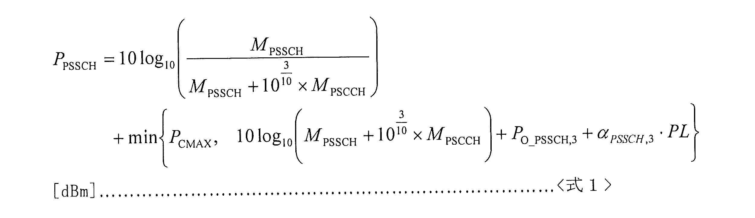
PSCCH送信のためのUE送信電力PPSCCHはPSSCH送信のためのPPSSCHと固定関係にあり、LTE V2Xにおけるサイドリンク送信モード3でのPSCCH送信のためのUE送信電力PPSCCHは、
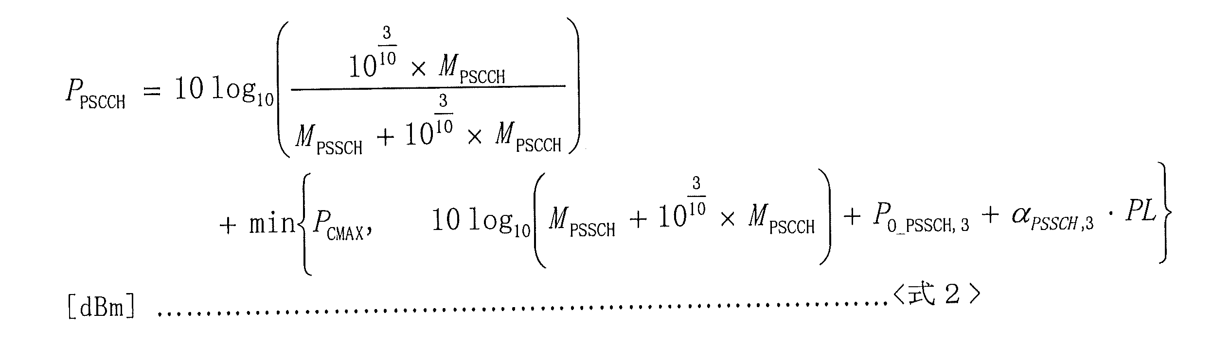
しかし、NRサイドリンクでは、電力制御をどのように決定するかはまだ不明確である。例えば、ダウンリンクでは、異なるビームに関連する複数のダウンリンクRSが存在し得、どのダウンリンクRS(またはビーム)が電力制御の決定に使用されるかが検討されねばならない。さらに、Tx UEとRx UEとの間のサイドリンクパスに基づく電力制御もサポートされる必要がありうる。 However, in the NR sidelink, it is still unclear how to determine power control. For example, in the downlink, there may be multiple downlink RSs associated with different beams, and it must be considered which downlink RS (or beam) is used to determine power control. In addition, power control based on the sidelink path between the Tx UE and the Rx UE may also need to be supported.
本開示は、上記を考慮して提供される。しかし、本開示は、V2Xに加えて他のD2D通信にも適用されうる。加えて、以下の実施形態は、NRサイドリンクモード1またはNRサイドリンクモード2であるものとして説明されうるが、指定されなければNRサイドリンクモード1およびモード2の両方、または将来のリリースで規定される任意の他の適切なモードに当てはまりうることに留意されたい。 The present disclosure is provided with the above in mind. However, the present disclosure may also be applied to other D2D communications in addition to V2X. In addition, it should be noted that although the following embodiments may be described as being NR sidelink mode 1 or NR sidelink mode 2, unless specified, they may apply to both NR sidelink mode 1 and mode 2, or any other suitable mode defined in a future release.
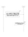
図1は、NRにおけるサイドリンク送信の例示的なシナリオを概略的に示す。図1に示されるように、gNB200はダウンリンク送信を介して車両101にダウンリンク信号を送信することができる。ダウンリンク信号は、例えばRS、DCIなどの制御情報でありうる。gNB200から車両101へのダウンリンク送信のために1つまたは複数のビームが存在し得、各ビームはそれぞれのダウンリンクRSを有しうる。さらに、信号送信は車両101から別の車両102にも、「サイドリンク送信」と記された2つの反対方向の矢印によって示されるサイドリンクを介して送信されうる。ここで、車両101は、適切に選択された任意のユーザ機器とすることができ、「車両」という用語は限定と見なされてはならない。さらに、gNB200から車両101への、または車両101と102との間の複数のビームがサポートされうる。
Figure 1 illustrates an example scenario of sidelink transmission in NR. As shown in Figure 1, gNB200 can transmit downlink signals to
例えば、一実施形態では、gNB200は、ダウンリンク送信としてPDCCHおよびPDSCHを車両101に送信することができ、車両101は、PUCCHおよびPUSCHをgNB200に送信する。車両101および102も、PSSCH、PSCCHおよび/またはPSFCHをサイドリンク送信として互いに送信することができる。
For example, in one embodiment, gNB 200 can transmit PDCCH and PDSCH as downlink transmissions to
車両101の詳細は、図2を参照することができる。図2は、本開示の一実施形態によるサイドリンク送信の電力制御の場合のUE100(例えば車両101および102)の詳細のブロック図を示す。特に、UE100は受信機110および回路120を含みうる。受信機110は、サイドリンク送信の電力決定基準の指示情報を受信するように動作し、指示情報は、ユーザ機器によって送信されるサイドリンクチャネルの電力制御に使用されるパスロスを決定するためのダウンリンクRSのセットを示し、または指示情報は、サイドリンクチャネルの電力制御に使用されるパスロスがサイドリンクRSに基づいて決定されることを示す。回路120は、指示情報に基づいてサイドリンクチャネルの電力制御に使用されるパスロスを決定する。ここで、ダウンリンクRSのセットは、1つまたは複数のダウンリンクRSを含むことができる。
For details of the
例えば、図1のgNB200は、車両101に(例えばダウンリンク制御情報(DCI:Downlink Control Information)または媒体アクセス制御制御要素(MAC‐CE:Medium Access Control‐Control Element)を介して)指示情報を動的に示すことができる。指示情報は、あるサイドリンクチャネルの電力制御に使用されるパスロスの決定が基づく特定のダウンリンクRS(すなわち1つの決定基準)を対象とすることができ、または指示情報は、サイドリンクチャネルの電力制御に使用されるパスロスがサイドリンクRSに基づいて決定されること(すなわち別の決定基準)を示すこともできる。本開示の一実施形態では、gNB200は、(例えば無線リソース制御(RRC:Radio Resource Control)情報を介して)指示情報を半動的に示すこともできる。 For example, gNB200 of FIG. 1 may dynamically indicate to vehicle 101 (e.g., via Downlink Control Information (DCI) or Medium Access Control-Control Element (MAC-CE)). The indication may be directed to a particular downlink RS on which a path loss used for power control of a sidelink channel is determined (i.e., one decision criterion), or the indication may indicate that the path loss used for power control of a sidelink channel is determined based on the sidelink RS (i.e., another decision criterion). In one embodiment of the present disclosure, gNB200 may also semi-dynamically indicate the indication (e.g., via Radio Resource Control (RRC) information).
指示情報がサイドリンクチャネルの電力制御に使用されるパスロスがサイドリンクRSに基づいて決定されることを示す場合には、車両101は、別のUE、例えば車両102からの(すなわちビームスイーピング)または複数のUEからの(すなわちグループキャスト)異なるサイドリンクビームに関連する複数のサイドリンクRSが存在するときには、例えば車両101の実装に基づいてサイドリンクチャネルの電力制御に使用されるパスロスを決定するために使用される特定のサイドリンクRSを決定することができる。ここで、「特定のダウンリンクRS」および「特定のサイドリンクRS」は、複数のダウンリンクRSまたはサイドリンクRSの特定の組み合わせでありうる。
If the indication information indicates that the path loss used for the power control of the sidelink channel is determined based on the sidelink RS, the
上述の実施形態の設定により、本発明は、複数の参照信号(または複数のビーム)が存在する場合に、サイドリンクチャネルの電力制御決定の目的で使用されるパスロスのための参照信号(単数または複数)または電力決定基準を示し、gNBがさまざまな目的に基づいてUEの電力を柔軟に制御する利点を達成する。 By configuring the above-mentioned embodiments, the present invention provides a reference signal(s) or power decision criteria for path loss to be used for power control decision purposes for sidelink channels when multiple reference signals (or multiple beams) exist, achieving the advantage of the gNB flexibly controlling the power of UEs based on various objectives.
一実施形態では、ユーザ機器の電力制御は、異なるリソース割当てモードで異なって行われる。例えば、NRモード1のUEの電力制御は、NRモード2のUEの電力制御とは異なって行われる。上述の実施形態の設定により、本発明は、異なるモードでUEの電力制御を最適化する利点を達成する。 In one embodiment, the power control of the user equipment is performed differently in different resource allocation modes. For example, the power control of a UE in NR mode 1 is performed differently from the power control of a UE in NR mode 2. By configuring the above-mentioned embodiment, the present invention achieves the advantage of optimizing the power control of the UE in different modes.
一実施形態では、ダウンリンクRSのセットは、プライマリ同期信号(PSS:Primary Synchronization Signal)、セカンダリ同期信号(SSS:Secondary Synchronization Signal)、および/またはチャネル状態情報参照信号(CSI‐RS:Channel State Information‐Reference Signal)を含みうる。任意の他のダウンリンクRSも適宜選択されうることに留意されたい。そして一実施形態では、PSS、SSSおよび/またはCSI‐RSは、1つまたは複数のダウンリンクビームを形成しうる。 In one embodiment, the set of downlink RSs may include a Primary Synchronization Signal (PSS), a Secondary Synchronization Signal (SSS), and/or a Channel State Information-Reference Signal (CSI-RS). Note that any other downlink RS may be selected accordingly. And in one embodiment, the PSS, SSS and/or CSI-RS may form one or more downlink beams.
一実施形態では、指示情報は、DCIを介したインデックスによりサイドリンク送信の電力決定基準を示し、サイドリンク送信の電力決定基準とインデックスとの関連付けは、RRC情報を介して設定されるか、予め設定されるかまたは規定される。例えば、指示情報は、以下の表1に示すように、DCIを介して2ビットフィールドによりサイドリンク送信の電力決定基準を示しうる。
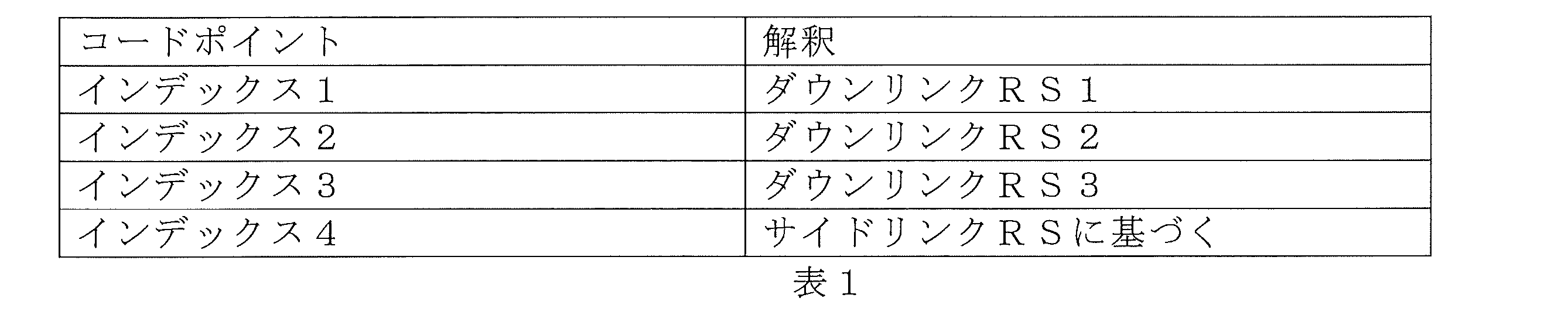
上述の実施形態の設定により、本発明は異なる目的に基づく動的電力制御の利点を達成し、gNBからUEにダウンリンク送信を介して送信される必要のある指示情報がより少なくなり(すなわちインデックスだけ)、それによりダウンリンク送信リソースが節約される。 By configuring the above-mentioned embodiments, the present invention achieves the advantage of dynamic power control based on different objectives, and less indication information (i.e., only an index) needs to be transmitted from the gNB to the UE via downlink transmission, thereby saving downlink transmission resources.
表1の実施形態では、サイドリンクパスのすべてまたは一部が同じ電力決定基準を使用する。しかし、サイドリンク送信の電力決定基準は、指示情報によって個別に決定されることもできる。一実施形態では、指示情報は、表1に示されるようにDCIを介して各2ビットフィールドによって各サイドリンクチャネルそれぞれのサイドリンク送信の電力決定基準を示しうる。例えば、指示情報の最初の2ビットは、表1に示すようにPSSCHの電力決定基準を示すことができ、指示情報の次の2ビットは、PSCCHの電力決定基準を示すことができ、指示情報の3番目の2ビットは、PSFCHの電力決定基準を示すことができる。 In the embodiment of Table 1, all or some of the sidelink paths use the same power decision criterion. However, the power decision criterion of the sidelink transmissions may also be determined individually by the indication information. In one embodiment, the indication information may indicate the power decision criterion of the sidelink transmissions of each sidelink channel by a respective 2-bit field via the DCI as shown in Table 1. For example, the first two bits of the indication information may indicate the power decision criterion of the PSSCH as shown in Table 1, the next two bits of the indication information may indicate the power decision criterion of the PSCCH, and the third two bits of the indication information may indicate the power decision criterion of the PSFCH.
加えて、サイドリンク送信の電力決定基準が個別に決定されうる場合、インデックスはダウンリンクRS/パスロスが単にサイドリンクRSに基づいて決定される場合または各2ビットがサイドリンクチャネルの解釈に使用される場合に対応することに限定されず、異なるサイドリンクチャネルに対するRS割当ての組み合わせに対応することもできる。例えば、指示情報は、以下の表2に示すように、DCIを介して2ビットフィールドによりサイドリンク送信の電力決定基準を示しうる。

上述の例では、電力決定基準に対する各インデックスの間のマッピングは、RRC設定を介して設定されるか、ユーザ機器で予め設定されるかもしくは規格にしたがって規定され、またはそれらの任意の組み合わせとすることができる。 In the above examples, the mapping between each index to the power decision criteria can be configured via RRC configuration, pre-configured in the user equipment, or specified according to a standard, or any combination thereof.
表2に示す例では、指示情報は、PSCCHおよびPSSCHに対して個別にサイドリンク送信の電力決定基準を示す。すなわち、PSCCHおよびPSSCHの電力制御に使用されるパスロスを決定するための参照信号(単数または複数)は、異なる参照信号または異なる組み合わせの参照信号でありうる。さらに別の実施形態では、指示情報は、PSCCHおよびPSSCHのサイドリンク送信の電力決定基準とは別に、物理サイドリンクフィードバックチャネル(PSFCH:Physical Sidelink Feedback Channel)のサイドリンク送信の電力決定基準を示しうる。指示情報がサイドリンクチャネルごとに個別に電力決定を示す場合でも、指示情報はPSCCH、PSSCHおよびPSFCHのうちのいずれか2つまたは3つについて同じ電力決定基準を示しうることに留意されたい。 In the example shown in Table 2, the indication information indicates the power decision criterion of sidelink transmission for PSCCH and PSSCH separately. That is, the reference signal(s) for determining the path loss used for power control of PSCCH and PSSCH may be different reference signals or different combinations of reference signals. In yet another embodiment, the indication information may indicate the power decision criterion of sidelink transmission for the physical sidelink feedback channel (PSFCH) separately from the power decision criterion of sidelink transmission for PSCCH and PSSCH. It should be noted that even if the indication information indicates the power decision separately for each sidelink channel, the indication information may indicate the same power decision criterion for any two or three of PSCCH, PSSCH, and PSFCH.
本発明の実施形態で言及される「2ビットフィールド」という用語は、限定と見なされてはならないことに留意されたい。特に、指示情報は、適切に選択された任意の数のビットのフィールドによってサイドリンク送信の電力決定基準を示しうる。さらに、指示情報は、各Nビットフィールドによって各サイドリンクチャネルそれぞれのサイドリンク送信の電力決定基準を示すことができ、Nも適宜選択されうる。あるいは、指示情報は、最初のN1ビットフィールドによって第一サイドリンクチャネルの電力決定基準を示すことができ、次のN2ビットフィールドによって第二サイドリンクチャネルの電力決定基準を示すことができ、…ここで、N1、N2…は、同じであることも異なることもできる。 It should be noted that the term "2-bit field" referred to in the embodiments of the present invention should not be considered as limiting. In particular, the indication information may indicate a power decision criterion for sidelink transmissions by a field of any appropriately selected number of bits. Furthermore, the indication information may indicate a power decision criterion for sidelink transmissions of each sidelink channel by a respective N-bit field, where N may also be selected appropriately. Alternatively, the indication information may indicate a power decision criterion for a first sidelink channel by a first N1-bit field and a power decision criterion for a second sidelink channel by a next N2- bit field, where N 1 , N 2 ... may be the same or different.
上述の実施形態の設定により、異なるチャネルが互いに異なる電力決定基準を有しうることから、本発明は異なるチャネルの(特にサイドリンクチャネルの)電力制御のより優れた柔軟性の利点を達成し、加えて、表2の例では、インデックスの使用により、gNBからUEにダウンリンク送信を介して送信される必要のある指示情報がより少なくて済む(すなわち複数のサイドリンクチャネルの電力決定基準を示す1つのインデックスだけ)。 By configuring the above-mentioned embodiment, the present invention achieves the advantage of greater flexibility in power control of different channels (especially sidelink channels), since different channels may have different power decision criteria from each other, and in addition, in the example of Table 2, the use of indexes requires less indication information to be transmitted from the gNB to the UE via downlink transmission (i.e. only one index indicating the power decision criteria for multiple sidelink channels).
さらに別の実施形態では、PSCCHの電力制御に使用されるパスロスとPSSCHの電力制御に使用されるパスロスとは、指示情報がPSCCHおよびPSSCHにつき同じ電力決定基準(例えば同じダウンリンクRS)を示す場合でも、固定された関係にある。例えば、PSCCHのパスロス=PSSCHのパスロス+オフセットである。ここで、オフセットは定数とすることができ、gNBによってRRCシグナリングを介して設定されるか、UEで予め設定されるか、または規格にしたがって規定されることができる。 In yet another embodiment, the path loss used for power control of the PSCCH and the path loss used for power control of the PSSCH have a fixed relationship even when the indication information indicates the same power decision criteria (e.g., the same downlink RS) for the PSCCH and the PSSCH. For example, PSCCH path loss = PSSCH path loss + offset, where the offset can be a constant and can be configured by the gNB via RRC signaling, pre-configured in the UE, or specified according to a standard.
上述の実施形態の設定により、本発明は、複数のサイドリンクチャネルの電力制御のためにより少ない参照信号に依存することができ、異なるチャネル間の電力制御のための参照信号の差も反映されることができ、それによって、さまざまなサイドリンクチャネルの電力制御に関してより単純なUE挙動および柔軟性が可能になるだけでなく、指示オーバーヘッドが節約される。 By configuring the above-mentioned embodiments, the present invention can rely on fewer reference signals for power control of multiple sidelink channels and can also reflect the difference in reference signals for power control between different channels, thereby not only enabling simpler UE behavior and flexibility with respect to power control of various sidelink channels, but also saving indication overhead.
上述の実施形態の応用例が、図3を参照して説明される。図3は、本開示の一実施形態によるユーザ機器のサイドリンク送信の例示的なシナリオのオプションを概略的に示す。図3に示すように、PSSCH/PSCCH多重化のオプション1A、オプション1Bおよびオプション3はすべて、PSCCHおよびPSSCHが時分割多重化(TDM:time division multiplexing)する場合に関する。オプション1Bでは、PSCCHおよびPSSCHはTDMであり、異なる帯域幅を有する。この場合、本発明による電力決定基準の別々の決定に基づいて電力制御を決定するPSCCHおよびPSSCHの実施形態が当てはまりうる。 An application example of the above-mentioned embodiment is described with reference to FIG. 3. FIG. 3 shows a schematic diagram of an exemplary scenario option of sidelink transmission of a user equipment according to an embodiment of the present disclosure. As shown in FIG. 3, PSSCH/PSCCH multiplexing option 1A, option 1B and option 3 all relate to the case where PSCCH and PSSCH are time division multiplexed (TDM). In option 1B, PSCCH and PSSCH are TDM and have different bandwidths. In this case, the embodiment of PSCCH and PSSCH determining power control based on separate determination of power decision criteria according to the present invention may apply.
上述の実施形態により、異なるチャネルで異なるカバレッジの場合に、本発明はダウンリンクチャネルの送信リソースを節約しながら各チャネルの電力決定基準を柔軟に示しうる。 By the above-mentioned embodiment, in the case of different coverage for different channels, the present invention can flexibly indicate the power decision criteria for each channel while saving the transmission resources of the downlink channel.
図3に示されるオプション3の場合、本発明による同じRSに基づいて電力制御を決定するPSCCHおよびPSSCHの実施形態が当てはまりうる。本発明による同じ電力決定基準に基づいて電力制御を決定するPSCCHおよびPSSCHの実施形態により、PSCCHを含むまたは含まないシンボルで一定の電力が達成されうる。 For option 3 shown in FIG. 3, the PSCCH and PSSCH embodiments in accordance with the present invention in which power control is determined based on the same RS may apply. With the PSCCH and PSSCH embodiments in accordance with the present invention in which power control is determined based on the same power determination criterion, constant power may be achieved for symbols with or without PSCCH.
上述の実施形態の設定により、本発明は、PSCCHを含むまたは含まないシンボルで一定の電力を保つことができる。 By configuring the above embodiment, the present invention can maintain constant power for symbols that do or do not include PSCCH.
上述の実施形態のさらなる応用例が、図4を参照して説明される。図4は、本開示の一実施形態によるユーザ機器のサイドリンク送信の別の例示的なシナリオを概略的に示す。特に、このシナリオでは2ステージのサイドリンク制御情報(SCI:Sidelink Control information)が示され、第一ステージのSCIはブロードキャストおよびセンシングを示すために使用され、第二ステージのSCIはユニキャスト/グループキャスト固有情報を示すために使用される。このシナリオでは、例えば、第一ステージのSCIを搬送するPSSCHおよびPSCCHは、同じ電力決定基準に基づいて電力制御を決定し、第二ステージのSCIを搬送するPSSCHおよびPSCCHは、異なる電力決定基準に基づいて電力制御を決定する。あるいは、第一ステージおよび第二ステージのSCIを搬送するPSSCHおよびPSCCHは、異なる電力決定基準に基づいて電力制御を決定する。 Further application of the above-mentioned embodiment is described with reference to FIG. 4. FIG. 4 illustrates another exemplary scenario of sidelink transmission of a user equipment according to an embodiment of the present disclosure. In particular, in this scenario, two-stage sidelink control information (SCI) is illustrated, where the first-stage SCI is used to indicate broadcast and sensing, and the second-stage SCI is used to indicate unicast/groupcast specific information. In this scenario, for example, the PSSCH and PSCCH carrying the first-stage SCI determine power control based on the same power decision criterion, and the PSSCH and PSCCH carrying the second-stage SCI determine power control based on different power decision criterion. Alternatively, the PSSCH and PSCCH carrying the first-stage and second-stage SCI determine power control based on different power decision criterion.
上述の実施形態により、本発明は、異なるサイドリンクチャネルで異なるカバレッジを達成することができ、これにより必要に応じた個々のサイドリンクチャネルの柔軟な電力制御が可能になる。 The above-described embodiments allow the present invention to achieve different coverage for different sidelink channels, thereby allowing flexible power control of individual sidelink channels as required.
一実施形態では、パスロスに加えて式1または2に関連して定義されるP0およびアルファなどのパラメータもサイドリンクチャネルの電力制御に使用されることができ、これらは設定されるか、予め設定されるか、またはサイドリンクチャネルの電力制御に使用されるパスロスに関連付けられることができる。P0は受信SINRのターゲット値を表し、アルファはパスロスの係数を表す。例えば、式1および2のおよびのパラメータPO_PSSCH,3およびαPSSCH,3は、gNBによって設定されるか、UEで予め設定されるかまたは規格にしたがって規定されることができる。すなわち、パラメータPO_PSSCH,3およびαPSSCH,3は、パスロスを決定するために使用されるすべてのビームまたはRSに共通である。別の例では、サイドリンクチャネルの電力制御に使用されるP0およびアルファなどのパスロス以外のパラメータが、パスロスの決定に使用されるサイドリンク送信の電力決定基準(例えば特定のダウンリンクRS)に関連付けられる。このようにして、サイドリンク送信の電力決定基準が例えばDCIによって示されると、送信されるサイドリンクチャネルの電力制御に使用されるパスロス、P0およびアルファの組み合わせが選択される。サイドリンク送信の電力制御は、式1または2と同じまたは類似の式を使用することができ、またはパスロスのパラメータならびに任意にP0およびアルファのパラメータを含む異なる式を使用することができることに留意されたい。 In one embodiment, parameters such as P0 and alpha defined in connection with Equation 1 or 2 in addition to path loss may also be used for power control of the sidelink channel, which may be configured, pre-configured, or associated with the path loss used for power control of the sidelink channel. P0 represents a target value of the received SINR, and alpha represents a coefficient of path loss. For example, the parameters P0_PSSCH,3 and αPSSCH,3 in Equations 1 and 2 may be configured by the gNB, pre-configured in the UE, or defined according to a standard. That is, the parameters P0_PSSCH,3 and αPSSCH,3 are common to all beams or RSs used to determine the path loss. In another example, parameters other than path loss such as P0 and alpha used for power control of the sidelink channel are associated with the power decision criterion of the sidelink transmission (e.g., a particular downlink RS) used for determining the path loss. In this way, the combination of path loss, P0, and alpha used for power control of the transmitted sidelink channel is selected when the power decision criterion of the sidelink transmission is indicated, for example, by DCI. It should be noted that the power control of sidelink transmissions can use equations the same as or similar to Equation 1 or 2, or can use different equations including parameters for path loss and optionally the P0 and alpha parameters.
ここで図1を再び参照すると、車両101は、車両102の電力決定基準を示すための指示情報を車両102に送信することもできる。特に図2を参照すると、UE100(例えば車両102)は、受信機110および回路120を含み、受信機110は、サイドリンク送信の電力決定基準の指示情報を受信するように動作し、指示情報は、ユーザ機器によって送信されるサイドリンクチャネルの電力制御に使用されるパスロスを決定するためのサイドリンク参照信号のセットを示し、回路120は、指示情報に基づいてサイドリンクチャネルの電力制御に使用されるパスロスを決定する。
Referring again to FIG. 1, the
一実施形態では、指示情報は、サイドリンク制御情報(SCI)を介して送信される。さらに別の実施形態では、サイドリンクチャネルは、物理サイドリンクフィードバックチャネル(PSFCH)である。上述の実施形態の設定により、両方のUEがRRC_IDLEモードのときでも、送信UEが受信UEにサイドリンクデータを送信するたびに受信UEのあるサイドリンクチャネル(例えばPSFCH)の電力制御がより柔軟なやり方で決定されうる。 In one embodiment, the indication information is transmitted via sidelink control information (SCI). In yet another embodiment, the sidelink channel is a physical sidelink feedback channel (PSFCH). With the configuration of the above embodiment, the power control of a certain sidelink channel (e.g., PSFCH) of the receiving UE can be determined in a more flexible manner every time the transmitting UE transmits sidelink data to the receiving UE, even when both UEs are in RRC_IDLE mode.
別の実施形態では、図1を参照して、例えば車両101はgNBからサイドリンク送信の電力決定基準に関する指示情報を受信しないこともある(例えばUEがRRC_IDLEモードにあるときに)。この場合、車両101は自分でパスロスのためのRSを決定することができる。特に図2を参照すると、一実施形態では、UE100は受信機110および回路120を含み、受信機110は、複数のダウンリンクまたはサイドリンクビームを受信するように動作し、回路120は、複数のダウンリンクまたはサイドリンクビームの中からユーザ機器によって決定された最良のダウンリンクまたはサイドリンクビームに関連する参照信号のセットに基づいてサイドリンクチャネルの電力制御に使用されるパスロスを決定する。
In another embodiment, referring to FIG. 1, for example, the
より具体的には、一実施形態では、UE100の受信機110は、gNBから複数のダウンリンクビームを受信しうる。次に、UE100の回路120は、複数のダウンリンクビームの中からUEによって決定された最良のダウンリンクビームに関連する参照信号のセットに基づいてサイドリンクチャネルの電力制御に使用されるパスロスを決定しうる。
More specifically, in one embodiment, the receiver 110 of the
別の実施形態では、UE100の受信機110は、別のUEから複数のサイドリンクビームを受信しうる。次に、UE100の回路120は、その別のUEから受信された複数のサイドリンクビームの中からUEによって決定された最良のサイドリンクビームに関連する参照信号のセットに基づいてサイドリンクチャネルの電力制御に使用されるパスロスを決定しうる。
In another embodiment, the receiver 110 of the
上述の実施形態の設定により、本発明は、gNBから指示情報が受信されない場合にUEが電力決定基準の選択を達成することを可能にし、ビームについての実際の情報に基づいて最適化も達成されうる。さらに、UEがRRC_IDLEモードにあるときのUEの電力決定基準に関する自律的決定が実現されうる。 By configuring the above-mentioned embodiment, the present invention enables the UE to achieve the selection of the power decision criterion when no indication information is received from the gNB, and optimization can also be achieved based on actual information about the beam. Furthermore, an autonomous decision regarding the power decision criterion of the UE when the UE is in RRC_IDLE mode can be realized.
一実施形態では、最良のダウンリンクビームは、特定の時間ウィンドウでユーザ機器によって測定される同期信号ブロック(SSB:Synchronization Signal Block)を受信するための最良のビームであり、または最良のサイドリンクビームは、UE(例えば車両101)とUE100と通信する別のUE(例えば車両102)との間のビーム管理に応じた最良のビームである。ここで、特定の時間ウィンドウは、gNBによって設定されるか、UEで予め設定されるかまたは規格にしたがって規定されることができる。
In one embodiment, the best downlink beam is the best beam for receiving a synchronization signal block (SSB) measured by the user equipment in a particular time window, or the best sidelink beam is the best beam according to beam management between the UE (e.g., vehicle 101) and another UE (e.g., vehicle 102) communicating with the
本開示における「指示情報」は、必ずしもgNBまたは別のUEから送信される最新の指示情報ではないことに留意されたい。例えば、次のサイドリンク送信のための指示情報がUEによって適切に受信されない場合、UEは例えばgNBからのDCIの最後の送信から受信された指示情報を使用しうる。デフォルト電力決定基準はさまざまな形式(例えば最良のビームに関連するダウンリンクRSまたはRRC設定)とすることができ、上述の例に限定されないことにも留意されたい。 It should be noted that the "indication information" in this disclosure is not necessarily the latest indication information transmitted from a gNB or another UE. For example, if the indication information for the next sidelink transmission is not properly received by the UE, the UE may use the indication information received, for example, from the last transmission of DCI from the gNB. It should also be noted that the default power decision criterion can be in various forms (e.g., downlink RS or RRC settings associated with the best beam) and is not limited to the above examples.
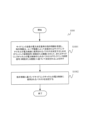
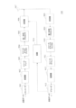
図5Aは、本開示の一実施形態によるユーザ機器によって行われるワイヤレス通信方法のフローチャートを示す。 FIG. 5A illustrates a flowchart of a wireless communication method performed by a user equipment according to one embodiment of the present disclosure.
図5Aに示すように、ユーザ機器によって行われるワイヤレス通信方法は、サイドリンク送信の電力決定基準の指示情報を受信するステップであって、指示情報は、ユーザ機器によって送信されるサイドリンクチャネルの電力制御に使用されるパスロスを決定するためのダウンリンク参照信号のセット、またはサイドリンクチャネルの電力制御のためのパスロスがサイドリンク参照信号に基づいて決定されることを示す、ステップS1001で始まる。 As shown in FIG. 5A, the wireless communication method performed by the user equipment starts with step S1001, which includes receiving an indication of a power determination criterion for sidelink transmissions, the indication indicating a set of downlink reference signals for determining a path loss to be used for power control of a sidelink channel transmitted by the user equipment, or indicating that the path loss for power control of the sidelink channel is determined based on the sidelink reference signals.
次に、ステップS1002で、UEは、指示情報に基づいてサイドリンクチャネルの電力制御に使用されるパスロスを決定する。ここで、UEは、図2に示すUE100または図1に示す車両101でありうる。UE100または車両101の上述の実施形態に関連する同様の利点も達成することができるが、詳細は省略する。
Next, in step S1002, the UE determines a path loss to be used for power control of the sidelink channel based on the indication information. Here, the UE may be the
一実施形態では、UEは、(例えばダウンリンク制御情報(DCI)または媒体アクセス制御制御要素(MAC‐CE)を介して)指示情報を受信しうる。指示情報は、あるサイドリンクチャネルの電力制御に使用されるパスロスの決定が基づく特定のダウンリンクRS(すなわち1つの決定基準)を対象とすることができ、または指示情報は、サイドリンクチャネルの電力制御に使用されるパスロスがサイドリンクRSに基づいて決定されること(すなわち別の決定基準)を示すこともできる。本開示の一実施形態では、無線リソース制御(RRC)情報を介して指示情報がUEに送信されうる。 In one embodiment, the UE may receive the indication (e.g., via a downlink control information (DCI) or a medium access control control element (MAC-CE)). The indication may be directed to a particular downlink RS on which a path loss used for power control of a sidelink channel is determined (i.e., one decision criterion), or the indication may indicate that the path loss used for power control of a sidelink channel is determined based on a sidelink RS (i.e., another decision criterion). In one embodiment of the present disclosure, the indication may be transmitted to the UE via radio resource control (RRC) information.
指示情報がサイドリンクチャネルの電力制御に使用されるパスロスがサイドリンクRSに基づいて決定されることを示す場合には、UEは、別のUEからの(すなわちビームスイーピング)または複数のUEからの(すなわちグループキャスト)異なるサイドリンクビームに関連する複数のサイドリンクRSが存在するときには、例えばUEの実装に基づいてサイドリンクチャネルの電力制御に使用されるパスロスを決定するために使用される特定のサイドリンクRSを決定しうる。ここで、「特定のダウンリンクRS」および「特定のサイドリンクRS」は、複数のダウンリンクRSまたはサイドリンクRSの特定の組み合わせでありうる。 If the indication information indicates that the path loss used for the power control of the sidelink channel is determined based on the sidelink RS, the UE may determine a specific sidelink RS to be used for determining the path loss used for the power control of the sidelink channel based on, for example, the UE implementation when there are multiple sidelink RSs associated with different sidelink beams from another UE (i.e., beam sweeping) or from multiple UEs (i.e., groupcast). Here, the "specific downlink RS" and "specific sidelink RS" may be a specific combination of multiple downlink RSs or sidelink RSs.
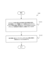
図5Bは、本開示の一実施形態によるユーザ機器によって行われるワイヤレス通信方法のフローチャートを示す。 FIG. 5B illustrates a flowchart of a wireless communication method performed by a user equipment according to one embodiment of the present disclosure.
図5Bに示すように、ユーザ機器によって行われるワイヤレス通信方法は、サイドリンク送信の電力決定基準の指示情報を受信するステップであって、指示情報は、ユーザ機器によって送信されるサイドリンクチャネルの電力制御に使用されるパスロスを決定するためのダウンリンク参照信号のセットを示す、ステップS1101で始まる。 As shown in FIG. 5B, the wireless communication method performed by the user equipment starts with step S1101, which includes receiving an indication of a power determination criterion for sidelink transmissions, the indication indicating a set of downlink reference signals for determining a path loss to be used for power control of a sidelink channel transmitted by the user equipment.
次に、ステップS1102で、UEは、指示情報に基づいてサイドリンクチャネルの電力制御に使用されるパスロスを決定する。ここで、UEは、図2に示すUE100または図1に示す車両102でありうる。UE100または車両102の上述の実施形態に関連する同様の利点も達成することができるが、詳細は省略する。
Next, in step S1102, the UE determines a path loss to be used for power control of the sidelink channel based on the indication information. Here, the UE may be the
一実施形態では、UEは、(例えばSCIを介して)指示情報を受信しうる。指示情報は、あるサイドリンクチャネルの電力制御に使用されるパスロスの決定が基づく特定のサイドリンクRSを対象としうる(すなわち1つの決定基準)。本開示の一実施形態では、電力制御が行われるサイドリンクチャネルはPSFCHである。 In one embodiment, the UE may receive an indication (e.g., via an SCI) that may be directed to a particular sidelink RS on which a path loss determination to be used for power control of a sidelink channel is based (i.e., a decision criterion). In one embodiment of the present disclosure, the sidelink channel on which power control is performed is the PSFCH.
一実施形態では、それからUEは、別のUEからの(すなわちビームスイーピング)または複数のUEからの(すなわちグループキャスト)異なるサイドリンクビームに関連する複数のサイドリンクRSが存在するときには、例えばUEの実装に基づいてサイドリンクチャネルの電力制御に使用されるパスロスを決定するために使用される特定のサイドリンクRSを決定しうる。ここで、「特定のサイドリンクRS」は、複数のサイドリンクRSの特定の組み合わせでありうる。 In one embodiment, the UE may then determine a specific sidelink RS to be used for determining the path loss used for power control of the sidelink channel, e.g., based on the UE implementation, when there are multiple sidelink RSs associated with different sidelink beams from another UE (i.e., beam sweeping) or from multiple UEs (i.e., groupcast). Here, the "specific sidelink RS" may be a specific combination of multiple sidelink RSs.
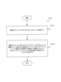
図6は、本開示の別の実施形態によるユーザ機器のためのワイヤレス通信方法2000のフローチャートを示す。
Figure 6 shows a flowchart of a
図6に示すように、UEによって行われるワイヤレス通信方法は、複数のダウンリンクまたはサイドリンクビームを受信するST2001のステップで始まる。ここで、各ダウンリンクまたはサイドリンクビームは、ダウンリンクRSのセットまたはサイドリンクRSのセットに関連しうる。ここで、UEは、図2に示すUE100または図1に示す車両101でありうる。UE100または車両101の上述の実施形態に関連する同様の利点も達成することができるが、詳細は省略する。
As shown in FIG. 6, the wireless communication method performed by the UE starts with step ST2001 of receiving multiple downlink or sidelink beams, where each downlink or sidelink beam may be associated with a set of downlink RSs or a set of sidelink RSs. Here, the UE may be the
次に、S2002のステップで、UEは、複数のダウンリンクビームまたはサイドリンクビームの中からUEによって決定された最良のダウンリンクまたはサイドリンクビームに関連するRSのセットに基づいてサイドリンクチャネルの電力制御に使用されるパスロスを決定する。 Next, in step S2002, the UE determines a path loss to be used for power control of the sidelink channel based on a set of RSs associated with the best downlink or sidelink beam determined by the UE from among multiple downlink or sidelink beams.
一実施形態では、サイドリンクチャネルの電力制御に使用されるパスロスが最良のダウンリンクビームに基づいて決定される場合(例えばモード1)、最良のダウンリンクビームは、特定の時間ウィンドウでUEによって測定される同期信号ブロック(SSB)を受信するための最良のビームであり、サイドリンクチャネルの電力制御に使用される電力が最良のサイドリンクビームに基づいて決定される場合(例えばモード2)、最良のサイドリンクビームは、UEと、UEと通信する別のUEとの間のビーム管理に応じた最良のビームである。 In one embodiment, when the path loss used for power control of the sidelink channel is determined based on the best downlink beam (e.g., mode 1), the best downlink beam is the best beam for receiving a synchronization signal block (SSB) measured by the UE in a particular time window, and when the power used for power control of the sidelink channel is determined based on the best sidelink beam (e.g., mode 2), the best sidelink beam is the best beam according to beam management between the UE and another UE communicating with the UE.
一実施形態では、サイドリンクチャネルの電力制御に使用されるパスロスが最良のサイドリンクに基づいて決定される場合にビーム管理がない場合、別のUEから受信された報告される参照信号受信電力のいずれがパスロスに使用されるかはUEの実装に基づく。 In one embodiment, in the absence of beam management where the path loss used for power control of the sidelink channel is determined based on the best sidelink, it is up to the UE implementation which of the reported reference signal received powers received from another UE is used for the path loss.
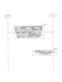
図7Aは、本開示の一実施形態による基地局とユーザ機器との間の通信のフローチャートの例を概略的に示す。特に、本開示の一実施形態によるgNB700とUE710との間の通信方法のフローチャートの例が示される。UE710は、例えば図2に示されるUE100または図1に示される車両101であり得、gNB700は、例えば図1に示されるgNB200でありうる。UE100または車両101の上述の実施形態に関連する同様の利点も達成することができるが、詳細は省略する。
Figure 7A shows an example of a flowchart of communication between a base station and a user equipment according to one embodiment of the present disclosure. In particular, an example of a flowchart of a communication method between a
図7Aに示すように、ステップST1101で、gNB700は、サイドリンク送信の電力決定基準の指示情報をUE710に送信することができ、指示情報は、ユーザ機器によって送信されるサイドリンクチャネルの電力制御に使用されるパスロスを決定するためのダウンリンク参照信号のセット、またはサイドリンクチャネルの電力制御のためのパスロスがサイドリンク参照信号に基づいて決定されることを示す。それに応答して、UE710は、gNB700から指示情報を受信しうる。ここで、ダウンリンクRSのセットは、1つまたは複数のダウンリンクRSを含むことができる。UE710は、図2に示すUE100または図1に示す車両101でありうる。
As shown in FIG. 7A, in step ST1101, gNB700 may transmit to UE710 an indication of a power determination criterion for sidelink transmission, the indication indicating a set of downlink reference signals for determining a path loss to be used for power control of a sidelink channel transmitted by the user equipment, or a path loss for power control of a sidelink channel is determined based on a sidelink reference signal. In response, UE710 may receive the indication information from gNB700. Here, the set of downlink RSs may include one or more downlink RSs. UE710 may be UE100 shown in FIG. 2 or
UE710がgNB700から指示情報を受信すると、UE710はステップST1102で、指示情報に基づいてサイドリンクチャネルの電力制御に使用されるパスロスを決定しうる。特に、UE710は、指示情報によって示される特定のダウンリンクRSのセットまたは使用される特定のサイドリンクRSのセットがさらに決定されるサイドリンクRSに基づいてサイドリンクチャネルの電力制御に使用されるパスロスを決定することもできる。
When
例えば、図7AのgNB700は、UE710に(例えばダウンリンク制御情報(DCI)または媒体アクセス制御制御要素(MAC‐CE)を介して)指示情報を動的に示すことができる。指示情報は、あるサイドリンクチャネルの電力制御に使用されるパスロスの決定が基づく特定のダウンリンクRS(すなわち1つの決定基準)を対象とすることができ、または指示情報は、サイドリンクチャネルの電力制御に使用されるパスロスがサイドリンクRSに基づいて決定されること(すなわち別の決定基準)を示すこともできる。本開示の一実施形態では、gNB700は、(例えば無線リソース制御(RRC:Radio Resource Control)情報を介して)指示情報を半動的に示すこともできる。
For example, the
指示情報がサイドリンクチャネルの電力制御に使用されるパスロスがサイドリンクRSに基づいて決定されることを示す場合、UE700は、別のUE、例えば車両102からの(すなわちビームスイーピング)または複数のUEからの(すなわちグループキャスト)異なるサイドリンクビームに関連する複数のサイドリンクRSが存在するときには、例えばUE700の実装に基づいてサイドリンクチャネルの電力制御に使用されるパスロスを決定するために使用される特定のサイドリンクRSを決定しうる。ここで、「特定のダウンリンクRS」および「特定のサイドリンクRS」は、複数のダウンリンクRSまたはサイドリンクRSの特定の組み合わせでありうる。
If the instruction information indicates that the path loss used for the power control of the sidelink channel is determined based on the sidelink RS, the
図7Bに示すように、ステップST1111で、UE710は、サイドリンク送信の電力決定基準の指示情報をUE720に送信することができ、指示情報は、ユーザ機器によって送信されるサイドリンクチャネルの電力制御に使用されるパスロスを決定するためのサイドリンク参照信号のセットを示す。それに応答して、UE720は、UE710から指示情報を受信しうる。ここで、ダウンリンクRSのセットは、1つまたは複数のダウンリンクRSを含むことができる。UE720は、図2に示すUE100または図1に示す車両102でありうる。
As shown in FIG. 7B, in step ST1111,
UE720がUE710から指示情報を受信すると、UE720はステップST1112で、指示情報に基づいてサイドリンクチャネルの電力制御に使用されるパスロスを決定しうる。特に、UE720は、指示情報によって示される特定のサイドリンクRSのセットに基づいてサイドリンクチャネルの電力制御に使用されるパスロスを決定しうる。
When
例えば、図7BのUE710は、UE720に(例えばSCIを介して)指示情報を動的に示しうる。指示情報は、あるサイドリンクチャネルの電力制御に使用されるパスロスの決定が基づく特定のサイドリンクRSを対象としうる。本開示の一実施形態では、電力制御が行われるサイドリンクチャネルはPSFCHである。
For example,
一実施形態では、それからUEは、別のUEからの(すなわちビームスイーピング)または複数のUEからの(すなわちグループキャスト)異なるサイドリンクビームに関連する複数のサイドリンクRSが存在するときには、例えばUEの実装に基づいてサイドリンクチャネルの電力制御に使用されるパスロスを決定するために使用される特定のサイドリンクRSを決定しうる。ここで、「特定のサイドリンクRS」は、複数のサイドリンクRSの特定の組み合わせでありうる。 In one embodiment, the UE may then determine a specific sidelink RS to be used for determining the path loss used for power control of the sidelink channel, e.g., based on the UE implementation, when there are multiple sidelink RSs associated with different sidelink beams from another UE (i.e., beam sweeping) or from multiple UEs (i.e., groupcast). Here, the "specific sidelink RS" may be a specific combination of multiple sidelink RSs.
図8は、本開示の別の実施形態による基地局/ユーザ機器と別のユーザ機器との間の通信のフローチャートの例を概略的に示す。特に、本開示の一実施形態によるgNB800とUE810との間の通信方法のフローチャートの例が示される。あるいは、図8に示される例は、UE810と別のUE820との間の通信にも当てはまりうる。UE810は、例えば図2に示されるUE100または図1に示される車両101であり得、gNB800は、例えば図1に示されるgNB200であり得、UE820は図1に示される車両102でありうる。UE100または車両101の上述の実施形態に関連する同様の利点も達成することができるが、詳細は省略する。
Figure 8 shows an example of a flowchart of communication between a base station/user equipment and another user equipment according to another embodiment of the present disclosure. In particular, an example of a flowchart of a communication method between a
図8に示すように、gNB800/UE820は、複数のダウンリンクまたはサイドリンクビームをUE810に送信する。これに応答して、UE810は、gNB800からの複数のダウンリンクビームまたは別のUE820からの複数のサイドリンクビームを受信する。ここで、各ダウンリンクまたはサイドリンクビームは、ダウンリンクRSのセットまたはサイドリンクRSのセットに関連しうる。 As shown in FIG. 8, gNB800/UE820 transmits multiple downlink or sidelink beams to UE810. In response, UE810 receives multiple downlink beams from gNB800 or multiple sidelink beams from another UE820. Here, each downlink or sidelink beam may be associated with a set of downlink RSs or a set of sidelink RSs.
複数のダウンリンクまたはサイドリンクビームの受信後に、UE810は、複数のダウンリンクまたはサイドリンクビームの中からUE810によって決定された最良のダウンリンクまたはサイドリンクビームに関連する参照信号のセットに基づいてサイドリンクチャネルの電力制御に使用されるパスロスを決定する。
After receiving multiple downlink or sidelink beams,
一実施形態では、サイドリンクチャネルの電力制御に使用されるパスロスが最良のダウンリンクビームに基づいて決定される場合(例えばモード1)、最良のダウンリンクビームは、特定の時間ウィンドウでユーザ機器によって測定される同期信号ブロック(SSB)を受信するための最良のビームであり、サイドリンクチャネルの電力制御に使用される電力が最良のサイドリンクビームに基づいて決定される場合(例えばモード2)、最良のサイドリンクビームは、ユーザ機器とユーザ機器と通信する別のユーザ機器との間のビーム管理に応じた最良のビームである。 In one embodiment, when the path loss used for power control of a sidelink channel is determined based on the best downlink beam (e.g., mode 1), the best downlink beam is the best beam for receiving a synchronization signal block (SSB) measured by the user equipment in a particular time window, and when the power used for power control of a sidelink channel is determined based on the best sidelink beam (e.g., mode 2), the best sidelink beam is the best beam according to beam management between the user equipment and another user equipment communicating with the user equipment.
一実施形態では、サイドリンクチャネルの電力制御に使用されるパスロスが最良のサイドリンクに基づいて決定される場合にビーム管理がない場合、別のUEから受信された報告される参照信号受信電力のいずれがパスロスに使用されるかはUEの実装に基づく。 In one embodiment, in the absence of beam management where the path loss used for power control of the sidelink channel is determined based on the best sidelink, it is up to the UE implementation which of the reported reference signal received powers received from another UE is used for the path loss.
図9は、本開示の一実施形態によるユーザ機器の例を体系的に示す。図9に示すように、UE100は、エンコーダ901、変調器902、リソースマッパ903、リソースマルチプレクサ904、第一信号プロセッサ905、送信機906、アンテナ907、受信機908、第二信号プロセッサ909、リソースデマルチプレクサ910、リソースデマッパ911、復調器912、デコーダ913、および制御回路914を含む。
9 systematically illustrates an example of a user equipment according to one embodiment of the present disclosure. As shown in FIG. 9, the
例えば、エンコーダ901は、送信データに対して符号化処理を行い、変調器902は、符号化後の送信データに対して変調処理を行ってデータシンボルを生成する。リソースマッパ903は、データシンボルを物理リソースにマッピングする。例えば、送信データがgNBに送信されるアップリンクデータに属するときには、リソースマッパ903は、データシンボルを、アップリンク送信および受信のために割当てられた帯域幅部分(BWP:Bandwidth Part)にマッピングする。リソースマルチプレクサ904は、データシンボルおよび考えられる制御情報および/または同期情報を多重化する。第一信号プロセッサ905は、リソースマルチプレクサ904から出力された多重化信号に対して信号処理を行う。送信機906は、処理されたアップリンク信号を、例えばgNBにアンテナ907を介して送信する。
For example, the
加えて、受信機908は、gNBからアンテナ907を介してダウンリンク送信を受信しうる。ダウンリンク送信は、サイドリンク送信の電力決定基準の指示情報を含むことができ、指示情報は、ユーザ機器によって送信されるサイドリンクチャネルの電力制御に使用されるパスロスを決定するためのダウンリンク参照信号のセット、またはサイドリンクチャネルの電力制御に使用されるパスロスがサイドリンク参照信号に基づいて決定されることを示す。第二信号プロセッサ909は、受信機908によって受信されたダウンリンク信号に対して信号処理を行う。リソースデマルチプレクサ910は、処理されたダウンリンク信号をダウンリンクデータおよび考えられるダウンリンク制御情報および/または同期情報に多重分離する。リソースデマッパ911は、物理リソースからサイドリンクデータシンボルおよび考えられるダウンリンク制御情報および/または同期情報をデマッピングする。復調器912は、ダウンリンクデータシンボルに対して復調処理を行い、デコーダ913は、復調されたダウンリンクデータシンボルに対して復号処理を行って、受信データを得る。加えて、復調器912は、考えられるダウンリンク制御情報および/または同期情報に対して復調処理を行うこともでき、デコーダ913は、復調されたダウンリンク制御情報および/または同期情報に対して復号処理を行って、サイドリンク送信および受信を制御するための指示情報を回路914に出力する。次に、回路914は、指示情報に基づいてサイドリンクチャネルの電力制御に使用されるパスロスを決定し、サイドリンクチャネルの送信のための送信機906の電力をさらに制御しうる。
In addition, the
一実施形態では、エンコーダ901によって行われる送信データが、別のUEに送信されるサイドリンクデータに属するときには、リソースマッパ903は、データシンボルをサイドリンク送信および受信のために割当てられたBWPにマッピングする。リソースマルチプレクサ904は、データシンボルおよび考えられる制御情報および/または同期情報を多重化する。第一信号プロセッサ905は、リソースマルチプレクサ904から出力された多重化信号に対して信号処理を行う。送信機906は、処理されたサイドリンク信号を、例えば別のUEにアンテナ907を介して送信する。
In one embodiment, when the transmission data made by the
一実施形態では、受信機908は、別のUEからアンテナ907を介してサイドリンク送信を受信しうる。サイドリンク送信は、複数のサイドリンクビームを含みうる。この場合、回路914は、複数のサイドリンクビームの中からUE100によって決定された最良のサイドリンクビームに関連する参照信号のセットに基づいてサイドリンクチャネルの電力制御に使用されるパスロスを決定しうる。一実施形態では、最良のサイドリンクビームは、ユーザ機器とUE100と通信する別のUEとの間のビーム管理に応じた最良のビームである。同様に、決定に基づいて、回路914は、サイドリンクチャネルの送信のための送信機906の電力を制御しうる。
In one embodiment, the
さらなる実施形態では、受信機908は、gNBからアンテナ907を介してダウンリンク送信を受信しうる。ダウンリンク送信は、複数のダウンリンクビームを含みうる。この場合、回路914は、複数のダウンリンクビームの中からUE100によって決定された最良のダウンリンクビームに関連する参照信号のセットに基づいてサイドリンクチャネルの電力制御に使用されるパスロスを決定しうる。一実施形態では、最良のダウンリンクビームは、特定の時間ウィンドウでユーザ機器によって測定される同期信号ブロック(SSB)を受信するための最良のビームである。
In a further embodiment, the
図9に示すUE100は、図2に示すUE100または図1に示す車両101として機能しうることに留意されたい。特に、受信機908は受信機120に対応しうる。回路120は、第二信号プロセッサ909、リソースデマルチプレクサ910、リソースデマッパ911、復調器912、デコーダ913、および回路914を含みうる。あるいは、これらのユニットのうちの1つまたは複数は、具体的要件に応じて回路120から分離されてもよい。UE100または車両101の上述の実施形態に関連する同様の利点も達成することができるが、詳細は省略する。
It should be noted that the
本開示は、ソフトウェアによって、ハードウェアによって、またはハードウェアと協働するソフトウェアによって、実施することができる。上述した各実施形態の説明において使用される各機能ブロックは、その一部または全体を、集積回路などのLSIによって実施することができ、各実施形態において説明した各プロセスは、その一部または全体を、同じLSIまたはLSIの組合せによって制御することができる。LSIは、チップとして個別に形成する、または、機能ブロックの一部またはすべてが含まれるように1個のチップを形成することができる。LSIは、自身に結合されたデータ入出力部を含むことができる。LSIは、集積度の違いに応じて、IC、システムLSI、スーパーLSI、またはウルトラLSIとも称される。しかしながら、集積回路を実施する技術は、LSIに限定されず、専用回路、汎用プロセッサ、または専用プロセッサを使用することによって実施することができる。さらには、LSIの製造後にプログラムすることのできるFPGA(フィールドプログラマブルゲートアレイ)や、LSI内部に配置されている回路セルの接続および設定を再設定できるリコンフィギャラブル・プロセッサを使用することもできる。本開示は、デジタル処理またはアナログ処理として実施することができる。半導体技術または別の派生技術が進歩する結果として、LSIが将来の集積回路技術に置き換わる場合、その将来の集積回路技術を使用して機能ブロックを集積化することができる。バイオテクノロジを適用することもできる。 The present disclosure can be implemented by software, hardware, or software working with hardware. Each functional block used in the description of each embodiment above can be implemented in part or in whole by an LSI such as an integrated circuit, and each process described in each embodiment can be controlled in part or in whole by the same LSI or a combination of LSIs. The LSI can be formed as a chip individually, or a single chip can be formed to include some or all of the functional blocks. The LSI can include a data input/output unit coupled to it. Depending on the degree of integration, the LSI can also be called an IC, a system LSI, a super LSI, or an ultra LSI. However, the technology for implementing the integrated circuit is not limited to the LSI, and can be implemented by using a dedicated circuit, a general-purpose processor, or a dedicated processor. Furthermore, an FPGA (field programmable gate array) that can be programmed after the LSI is manufactured, or a reconfigurable processor that can reconfigure the connections and settings of the circuit cells arranged inside the LSI can also be used. The present disclosure can be implemented as digital processing or analog processing. If LSI is replaced by a future integrated circuit technology as a result of advances in semiconductor technology or other derivative technologies, the future integrated circuit technology can be used to integrate the functional blocks. Biotechnology can also be applied.
本開示は、通信装置と呼称される通信の機能を有する任意の種類の装置、デバイスまたはシステムによって実現されうる。 The present disclosure may be realized by any type of apparatus, device or system having communication capabilities, referred to as a communication apparatus.
そのような通信装置のいくつかの非限定的な例には、電話(例えばセルラ(携帯)電話、スマートフォン)、タブレット、パーソナルコンピュータ(PC)(例えばラップトップ、デスククトップ、ネットブック)、カメラ(例えばデジタルスチル/ビデオカメラ)、デジタルプレーヤ(デジタルオーディオ/ビデオプレーヤ)、ウェアラブルデバイス(例えばウェアラブルカメラ、スマートウォッチ、追跡デバイス)、ゲームコンソール、デジタルブックリーダ、テレヘルス/テレ医療(遠隔ヘルスおよび医療)デバイス、および通信機能を提供する車両(例えば自動車、飛行機、船)、ならびにこれらのさまざまな組み合わせが含まれる。 Some non-limiting examples of such communication devices include phones (e.g., cellular phones, smartphones), tablets, personal computers (PCs) (e.g., laptops, desktops, netbooks), cameras (e.g., digital still/video cameras), digital players (digital audio/video players), wearable devices (e.g., wearable cameras, smart watches, tracking devices), game consoles, digital book readers, telehealth/telemedical (remote health and medical) devices, and vehicles (e.g., cars, airplanes, ships) that provide communication capabilities, as well as various combinations thereof.
通信装置は、携帯型または移動式に限定されず、スマートホームデバイス(例えば電化製品、照明、スマートメータ、制御パネル)、自動販売機、および「モノのインターネット(IoT:Internet of Things)」のネットワーク内の任意の他の「モノ」など、非携帯型または固定式の任意の種類の装置、デバイス、またはシステムも含みうる。 The communication devices are not limited to being portable or mobile, but may also include any type of equipment, device, or system that is non-portable or fixed, such as smart home devices (e.g., appliances, lights, smart meters, control panels), vending machines, and any other "things" in the "Internet of Things" (IoT) network.
通信は、例えばセルラシステム、ワイヤレスLANシステム、衛星システムなど、およびそれらのさまざまな組み合わせを介したデータ交換を含みうる。 Communications may include, for example, data exchange via cellular systems, wireless LAN systems, satellite systems, etc., and various combinations thereof.
通信装置は、本開示に記載の通信の機能を行う通信デバイスに連結されたコントローラまたはセンサなどのデバイスを含みうる。例えば、通信装置は、通信装置の通信機能を行う通信デバイスによって使用される制御信号またはデータ信号を生成するコントローラまたはセンサを含みうる。 A communication apparatus may include devices such as a controller or a sensor coupled to a communication device that performs the communication functions described in this disclosure. For example, a communication apparatus may include a controller or a sensor that generates control or data signals used by the communication device to perform the communication functions of the communication apparatus.
通信装置は、基地局、アクセスポイントなどのインフラストラクチャ設備、および上記の非限定的な例などの装置と通信するかまたはそれらを制御する任意の他の装置、デバイスまたはシステムも含みうる。 Communication equipment may also include infrastructure facilities such as base stations, access points, and any other equipment, devices or systems that communicate with or control equipment such as the non-limiting examples above.
本開示の実施形態は、少なくとも以下の主題を提供しうる。
(1)サイドリンク送信の電力決定基準の指示情報を受信する受信機であって、指示情報は、ユーザ機器によって送信されるサイドリンクチャネルの電力制御に使用されるパスロスを決定するためのダウンリンク参照信号のセット、またはサイドリンクチャネルの電力制御のためのパスロスがサイドリンク参照信号に基づいて決定されることを示す、受信機と、
指示情報に基づいてサイドリンクチャネルの電力制御に使用されるパスロスを決定する回路と
を含むユーザ機器。
The embodiments of the present disclosure may provide at least the following subject matter.
(1) A receiver for receiving an indication of a power determination criterion for a sidelink transmission, the indication indicating a set of downlink reference signals for determining a path loss to be used for power control of a sidelink channel transmitted by a user equipment, or a path loss for power control of the sidelink channel being determined based on the sidelink reference signals;
and a circuit for determining a path loss to be used for power control of a sidelink channel based on the indication information.
(2)ユーザ機器の電力制御は、異なるリソース割当てモードで異なって行われる、
(1)に記載のユーザ機器。
(2) User equipment power control is performed differently in different resource allocation modes;
A user equipment as described in (1).
(3)指示情報は、ダウンリンク制御情報(DCI)、無線リソース制御(RRC)情報、媒体アクセス制御(MAC)情報またはそれらの任意の組み合わせのうちの少なくとも1つを介して送信される、
(1)または(2)に記載のユーザ機器。
(3) the indication information is transmitted via at least one of downlink control information (DCI), radio resource control (RRC) information, medium access control (MAC) information, or any combination thereof;
A user equipment according to (1) or (2).
(4)指示情報は、ダウンリンク制御情報(DCI)を介したインデックスによりサイドリンク送信の電力決定基準を示し、
サイドリンク送信の電力決定基準とインデックスとの関連付けは、無線リソース制御(RRC)情報を介して設定されるか、予め設定されるかまたは規定される、
(3)に記載のユーザ機器。
(4) The indication information indicates a power decision criterion for sidelink transmission by an index via downlink control information (DCI);
The association of the power decision criterion for the sidelink transmission with the index is configured, pre-configured or defined via Radio Resource Control (RRC) information.
(3) A user equipment according to the present invention.
(5)ダウンリンク参照信号のセットは、プライマリ同期信号(PSS)、セカンダリ同期信号(SSS)、およびチャネル状態情報参照信号(CSI‐RS)のうちの少なくとも1つを含む、
(1)~(3)のいずれか1つに記載のユーザ機器。
(5) The set of downlink reference signals includes at least one of a primary synchronization signal (PSS), a secondary synchronization signal (SSS), and a channel state information reference signal (CSI-RS).
A user equipment according to any one of (1) to (3).
(6)ダウンリンク参照信号のセットのプライマリ同期信号(PSS)、セカンダリ同期信号(SSS)、および/またはチャネル状態情報参照信号(CSI‐RS)は、1つまたは複数のダウンリンクビームを形成する、
(5)に記載のユーザ機器。
(6) A primary synchronization signal (PSS), a secondary synchronization signal (SSS), and/or a channel state information reference signal (CSI-RS) of a set of downlink reference signals form one or more downlink beams.
(5) A user equipment according to the present invention.
(7)指示情報は、物理サイドリンク制御チャネル(PSCCH)および物理サイドリンク共有チャネル(PSSCH)に対して個別にサイドリンク送信の電力決定基準を示す、
(1)~(6)のいずれか1つに記載のユーザ機器。
(7) The indication information indicates a power decision criterion for sidelink transmissions separately for a physical sidelink control channel (PSCCH) and a physical sidelink shared channel (PSSCH).
A user equipment according to any one of (1) to (6).
(8)指示情報は、物理サイドリンク制御チャネル(PSCCH)および物理サイドリンク共有チャネル(PSSCH)のサイドリンク送信の電力決定基準とは別に、物理サイドリンクフィードバックチャネル(PSFCH)のサイドリンク送信の電力決定基準を示す、
(1)~(7)のいずれか1つに記載のユーザ機器。
(8) The indication information indicates a power decision criterion for a sidelink transmission of a physical sidelink feedback channel (PSFCH) separately from a power decision criterion for sidelink transmission of a physical sidelink control channel (PSCCH) and a physical sidelink shared channel (PSSCH).
A user equipment according to any one of (1) to (7).
(9)指示情報は、物理サイドリンク制御チャネル(PSCCH)、物理サイドリンク共有チャネル(PSSCH)、および物理サイドリンクフィードバックチャネル(PSFCH)のうちのいずれか2つまたは3つについて同じ電力決定基準を示す、
(1)~(8)のいずれか1つに記載のユーザ機器。
(9) The indication information indicates the same power decision criterion for any two or three of the physical sidelink control channel (PSCCH), the physical sidelink shared channel (PSSCH), and the physical sidelink feedback channel (PSFCH).
A user equipment according to any one of (1) to (8).
(10)PSCCHの電力制御に使用されるパスロスとPSSCHの電力制御に使用されるパスロスとは固定された関係にある、
(7)に記載のユーザ機器。
(10) The path loss used for the power control of the PSCCH and the path loss used for the power control of the PSSCH have a fixed relationship.
(7) A user equipment according to the present invention.
(11)サイドリンクチャネルの電力制御に使用されるP(0)およびアルファのパラメータは、設定されるか、予め設定されるか、またはサイドリンクチャネルの電力制御に使用されるパスロスに関連付けられる、
(1)に記載のユーザ機器。
(11) The P(0) and alpha parameters used for power control of the sidelink channel are configured, preconfigured, or associated with a path loss used for power control of the sidelink channel.
A user equipment as described in (1).
(12)サイドリンク送信の電力決定基準の指示情報を受信する受信機であって、指示情報は、ユーザ機器によって送信されるサイドリンクチャネルの電力制御に使用されるパスロスを決定するためのサイドリンク参照信号のセットを示す、受信機と、
指示情報に基づいてサイドリンクチャネルの電力制御に使用されるパスロスを決定する回路と
を含むユーザ機器。
(12) A receiver for receiving an indication of a power decision criterion for a sidelink transmission, the indication indicating a set of sidelink reference signals for determining a path loss to be used for power control of a sidelink channel transmitted by a user equipment; and
and a circuit for determining a path loss to be used for power control of a sidelink channel based on the indication information.
(13)指示情報は、サイドリンク制御情報(SCI)を介して送信される、
(12)に記載のユーザ機器。
(13) The indication information is transmitted via sidelink control information (SCI).
(12) A user equipment according to the present invention.
(14)サイドリンクチャネルは、物理サイドリンクフィードバックチャネル(PSFCH)である、
(12)または(13)に記載のユーザ機器。
(14) The sidelink channel is a physical sidelink feedback channel (PSFCH).
A user equipment according to (12) or (13).
(15)複数のダウンリンクまたはサイドリンクビームを受信する受信機と、
複数のダウンリンクまたはサイドリンクビームの中からユーザ機器によって決定された最良のダウンリンクまたはサイドリンクビームに関連する参照信号のセットに基づいてサイドリンクチャネルの電力制御に使用されるパスロスを決定する回路と
を含むユーザ機器。
(15) A receiver for receiving a plurality of downlink or sidelink beams;
and a circuit for determining a path loss to be used for power control of a sidelink channel based on a set of reference signals associated with a best downlink or sidelink beam determined by the user equipment from among a plurality of downlink or sidelink beams.
(16)最良のダウンリンクビームは、特定の時間ウィンドウでユーザ機器によって測定される同期信号ブロック(SSB)を受信するための最良のビームであり、または
最良のサイドリンクビームは、ユーザ機器とユーザ機器と通信する別のユーザ機器との間のビーム管理に応じた最良のビームである、
(13)に記載のユーザ機器。
(16) The best downlink beam is the best beam for receiving a synchronization signal block (SSB) measured by a user equipment in a particular time window; or the best sidelink beam is the best beam according to beam management between the user equipment and another user equipment communicating with the user equipment.
(13) A user equipment according to the present invention.
(17)ユーザ機器のためのワイヤレス通信方法であって、
サイドリンク送信の電力決定基準の指示情報を受信するステップであって、指示情報は、ユーザ機器によって送信されるサイドリンクチャネルの電力制御に使用されるパスロスを決定するためのダウンリンク参照信号のセット、またはサイドリンクチャネルの電力制御のためのパスロスがサイドリンク参照信号に基づいて決定されることを示す、ステップと、
指示情報に基づいてサイドリンクチャネルの電力制御に使用されるパスロスを決定するステップと
を含むワイヤレス通信方法。
(17) A wireless communication method for a user equipment, comprising:
receiving an indication of a power decision criterion for sidelink transmissions, the indication indicating a set of downlink reference signals for determining a pathloss to be used for power control of a sidelink channel transmitted by the user equipment or that a pathloss for power control of the sidelink channel is determined based on the sidelink reference signals;
determining a path loss to be used for power control of a sidelink channel based on the indication information.
(18)ユーザ機器の電力制御は、異なるリソース割当てモードで異なって行われる、
(17)に記載のワイヤレス通信方法。
(18) Power control of a user equipment is performed differently in different resource allocation modes;
(17) A wireless communication method according to (17).
(19)指示情報は、ダウンリンク制御情報(DCI)、無線リソース制御(RRC)情報、媒体アクセス制御(MAC)情報またはそれらの任意の組み合わせのうちの少なくとも1つを介して送信される、
(17)または(18)に記載のワイヤレス通信方法。
(19) The indication information is transmitted via at least one of downlink control information (DCI), radio resource control (RRC) information, medium access control (MAC) information, or any combination thereof.
A wireless communication method according to (17) or (18).
(20)指示情報は、ダウンリンク制御情報(DCI)を介したインデックスによりサイドリンク送信の電力決定基準を示し、
サイドリンク送信の電力決定基準とインデックスとの関連は、無線リソース制御(RRC)情報を介して設定されるか、予め設定されるかまたは規定される、
(19)に記載のユーザ機器。
(20) The indication information indicates a power decision criterion for sidelink transmission by an index via downlink control information (DCI);
The association between the power decision criterion for the sidelink transmission and the index is configured, pre-configured or defined via Radio Resource Control (RRC) information.
(19) A user equipment according to the present invention.
(21)ダウンリンク参照信号のセットは、プライマリ同期信号(PSS)、セカンダリ同期信号(SSS)、およびチャネル状態情報参照信号(CSI‐RS)のうちの少なくとも1つを含む、
(17)~(19)のいずれか1つに記載のユーザ機器。
(21) The set of downlink reference signals includes at least one of a primary synchronization signal (PSS), a secondary synchronization signal (SSS), and a channel state information reference signal (CSI-RS).
A user equipment according to any one of (17) to (19).
(22)ダウンリンク参照信号のセットのプライマリ同期信号(PSS)、セカンダリ同期信号(SSS)、および/またはチャネル状態情報参照信号(CSI‐RS)は、1つまたは複数のダウンリンクビームを形成する、
(21)に記載のユーザ機器。
(22) A primary synchronization signal (PSS), a secondary synchronization signal (SSS), and/or a channel state information reference signal (CSI-RS) of a set of downlink reference signals form one or more downlink beams.
(21) A user equipment according to the present invention.
(23)指示情報は、物理サイドリンク制御チャネル(PSCCH)および物理サイドリンク共有チャネル(PSSCH)に対して個別にサイドリンク送信の電力決定基準を示す、
(17)~(22)のいずれか1つに記載のユーザ機器。
(23) The indication information indicates a power decision criterion for sidelink transmissions separately for a physical sidelink control channel (PSCCH) and a physical sidelink shared channel (PSSCH).
A user equipment according to any one of (17) to (22).
(24)指示情報は、物理サイドリンク制御チャネル(PSCCH)および物理サイドリンク共有チャネル(PSSCH)のサイドリンク送信の電力決定基準とは別に、物理サイドリンクフィードバックチャネル(PSFCH)のサイドリンク送信の電力決定基準を示す、
(17)~(23)のいずれか1つに記載のユーザ機器。
(24) The indication information indicates a power decision criterion for a sidelink transmission of a physical sidelink feedback channel (PSFCH) separately from a power decision criterion for sidelink transmission of a physical sidelink control channel (PSCCH) and a physical sidelink shared channel (PSSCH).
A user equipment according to any one of (17) to (23).
(25)指示情報は、物理サイドリンク制御チャネル(PSCCH)、物理サイドリンク共有チャネル(PSSCH)、および物理サイドリンクフィードバックチャネル(PSFCH)のうちのいずれか2つまたは3つについて同じ電力決定基準を示す、
(17)~(24)のいずれか1つに記載のユーザ機器。
(25) The indication information indicates the same power decision criterion for any two or three of a physical sidelink control channel (PSCCH), a physical sidelink shared channel (PSSCH), and a physical sidelink feedback channel (PSFCH).
A user equipment according to any one of (17) to (24).
(26)PSCCHの電力制御に使用されるパスロスとPSSCHの電力制御に使用されるパスロスとは固定された関係にある、
(25)に記載のユーザ機器。
(26) A path loss used for power control of the PSCCH and a path loss used for power control of the PSSCH have a fixed relationship.
(25) A user equipment according to the present invention.
(27)サイドリンクチャネルの電力制御に使用されるP(0)およびアルファのパラメータは、設定されるか、予め設定されるか、またはサイドリンクチャネルの電力制御に使用されるパスロスに関連付けられる、
(17)に記載のユーザ機器。
(27) The P(0) and alpha parameters used for power control of a sidelink channel are configured, preconfigured, or associated with a path loss used for power control of the sidelink channel.
(17) A user equipment according to the present invention.
(28)ユーザ機器のためのワイヤレス通信方法であって、
サイドリンク送信の電力決定基準の指示情報を受信するステップであって、指示情報は、ユーザ機器によって送信されるサイドリンクチャネルの電力制御に使用されるパスロスを決定するためのサイドリンク参照信号のセットを示す、ステップと、
指示情報に基づいてサイドリンクチャネルの電力制御に使用されるパスロスを決定するステップと
を含むワイヤレス通信方法。
(28) A wireless communication method for a user equipment, comprising:
receiving an indication of a power decision criterion for sidelink transmissions, the indication indicating a set of sidelink reference signals for determining a path loss to be used for power control of a sidelink channel transmitted by the user equipment;
determining a path loss to be used for power control of a sidelink channel based on the indication information.
(29)指示情報は、サイドリンク制御情報(SCI)を介して送信される、
(28)に記載のワイヤレス通信方法。
(29) The indication information is transmitted via sidelink control information (SCI).
(28) A wireless communication method according to (28).
(30)サイドリンクチャネルは、物理サイドリンクフィードバックチャネル(PSFCH)である、
(28)または(29)に記載のワイヤレス通信方法。
(30) The sidelink channel is a physical sidelink feedback channel (PSFCH).
A wireless communication method according to (28) or (29).
(31)ユーザ機器のためのワイヤレス通信方法であって、
複数のダウンリンクまたはサイドリンクビームを受信するステップと、
複数のダウンリンクまたはサイドリンクビームの中からユーザ機器によって決定された最良のダウンリンクまたはサイドリンクビームに関連する参照信号のセットに基づいてサイドリンクチャネルの電力制御に使用されるパスロスを決定するステップと
を含むワイヤレス通信方法。
(31) A wireless communication method for a user equipment, comprising:
receiving a plurality of downlink or sidelink beams;
determining a path loss to be used for power control of a sidelink channel based on a set of reference signals associated with a best downlink or sidelink beam determined by the user equipment from among a plurality of downlink or sidelink beams.
(32)最良のダウンリンクビームは、特定の時間ウィンドウでユーザ機器によって測定される同期信号ブロック(SSB)を受信するための最良のビームであり、または
最良のサイドリンクビームは、ユーザ機器とユーザ機器と通信する別のユーザ機器との間のビーム管理に応じた最良のビームである、
(31)に記載のワイヤレス通信方法。
(32) The best downlink beam is the best beam for receiving a synchronization signal block (SSB) measured by a user equipment in a particular time window; or the best sidelink beam is the best beam according to beam management between the user equipment and another user equipment communicating with the user equipment.
(31) A wireless communication method according to (31).
Claims (15)
前記指示情報を送信する送信機と、を具備し、
前記指示情報が前記サイドリンクチャネルの前記電力制御におけるパスロスの決定にサイドリンク参照信号又はダウンリンク参照信号が用いられることを示し、前記指示情報に基づいて前記パスロスの決定にダウンリンク参照信号が用いられる場合、複数のダウンリンク参照信号から特定された1つのダウンリンク参照信号に基づいて前記パスロスを決定し、前記複数のダウンリンク参照信号の各々は複数のビームのいずれかに関連し、前記サイドリンクチャネルの前記電力制御に用いられるパラメータP0及びパラメータアルファは前記複数のビームにおいて共通である、
基地局。 a circuit for generating an indication regarding power control for a transmission of a sidelink channel;
A transmitter for transmitting the instruction information,
The instruction information indicates that a sidelink reference signal or a downlink reference signal is used to determine a path loss in the power control of the sidelink channel, and when a downlink reference signal is used to determine the path loss based on the instruction information, the path loss is determined based on one downlink reference signal identified from a plurality of downlink reference signals, each of the plurality of downlink reference signals is associated with one of a plurality of beams, and a parameter P0 and a parameter alpha used in the power control of the sidelink channel are common to the plurality of beams.
Base station.
請求項1に記載の基地局。 The instruction information is transmitted by downlink control information, radio resource control information, MAC information, or a combination thereof.
The base station according to claim 1 .
請求項1に記載の基地局。 The one set of downlink reference signals includes a first synchronization signal or a second synchronization signal;
The base station according to claim 1 .
請求項3に記載の基地局。 The first synchronization signal or the second synchronization signal in the one downlink reference signal set is associated with one or more downlink beams.
The base station according to claim 3.
請求項1に記載の基地局。 the indication information indicates the power control of a physical sidelink shared channel and the power control of a physical sidelink feedback channel.
The base station according to claim 1 .
請求項1に記載の基地局。 The parameter P0 and the parameter alpha used for the power control of the sidelink channel are selected based on the instruction information.
The base station according to claim 1 .
請求項1に記載の基地局。 In a first case where the sidelink reference signal is used for the path loss determination and in a second case where a downlink reference signal is used for the path loss determination, the power control of the sidelink channel uses different equations.
The base station according to claim 1 .
前記指示情報を送信し、
前記指示情報が前記サイドリンクチャネルの前記電力制御におけるパスロスの決定にサイドリンク参照信号又はダウンリンク参照信号が用いられることを示し、前記指示情報に基づいて前記パスロスの決定にダウンリンク参照信号が用いられる場合、複数のダウンリンク参照信号から特定された1つのダウンリンク参照信号に基づいて前記パスロスを決定し、前記複数のダウンリンク参照信号の各々は複数のビームのいずれかに関連し、前記サイドリンクチャネルの前記電力制御に用いられるパラメータP0及びパラメータアルファは前記複数のビームにおいて共通である、
通信方法。 generating power control indications for transmission of the sidelink channel;
Transmitting the instruction information;
The instruction information indicates that a sidelink reference signal or a downlink reference signal is used to determine a path loss in the power control of the sidelink channel, and when a downlink reference signal is used to determine the path loss based on the instruction information, the path loss is determined based on one downlink reference signal identified from a plurality of downlink reference signals, each of the plurality of downlink reference signals is associated with one of a plurality of beams, and a parameter P0 and a parameter alpha used in the power control of the sidelink channel are common to the plurality of beams.
Communication methods.
請求項8に記載の通信方法。 The instruction information is transmitted by downlink control information, radio resource control information, MAC information, or a combination thereof.
The communication method according to claim 8.
請求項8に記載の通信方法。 The one set of downlink reference signals includes a first synchronization signal or a second synchronization signal;
The communication method according to claim 8.
請求項10に記載の通信方法。 The first synchronization signal or the second synchronization signal in the one downlink reference signal set is associated with one or more downlink beams.
The communication method according to claim 10.
請求項8に記載の通信方法。 the indication information indicates the power control of a physical sidelink shared channel and the power control of a physical sidelink feedback channel.
The communication method according to claim 8.
請求項8に記載の通信方法。 The parameter P0 and the parameter alpha used for the power control of the sidelink channel are selected based on the instruction information.
The communication method according to claim 8.
請求項8に記載の通信方法。 In a first case where the sidelink reference signal is used for the path loss determination and in a second case where a downlink reference signal is used for the path loss determination, the power control of the sidelink channel uses different equations.
The communication method according to claim 8.
前記指示情報を送信する処理と、を制御し、
前記指示情報が前記サイドリンクチャネルの前記電力制御におけるパスロスの決定にサイドリンク参照信号又はダウンリンク参照信号が用いられることを示し、前記指示情報に基づいて前記パスロスの決定にダウンリンク参照信号が用いられる場合、複数のダウンリンク参照信号から特定された1つのダウンリンク参照信号に基づいて前記パスロスを決定し、前記複数のダウンリンク参照信号の各々は複数のビームのいずれかに関連し、前記サイドリンクチャネルの前記電力制御に用いられるパラメータP0及びパラメータアルファは前記複数のビームにおいて共通である、
集積回路。 generating a power control indication for a sidelink channel transmission;
A process of transmitting the instruction information;
The instruction information indicates that a sidelink reference signal or a downlink reference signal is used to determine a path loss in the power control of the sidelink channel, and when a downlink reference signal is used to determine the path loss based on the instruction information, the path loss is determined based on one downlink reference signal identified from a plurality of downlink reference signals, each of the plurality of downlink reference signals is associated with one of a plurality of beams, and a parameter P0 and a parameter alpha used in the power control of the sidelink channel are common to the plurality of beams.
Integrated circuits.
Priority Applications (1)
| Application Number | Priority Date | Filing Date | Title |
|---|---|---|---|
| JP2023131049A JP7547582B2 (en) | 2019-03-28 | 2023-08-10 | Base station, communication method and integrated circuit |
Applications Claiming Priority (3)
| Application Number | Priority Date | Filing Date | Title |
|---|---|---|---|
| JP2021551954A JP7333407B2 (en) | 2019-03-28 | 2019-03-28 | Terminal, communication method and integrated circuit |
| PCT/CN2019/080035 WO2020191699A1 (en) | 2019-03-28 | 2019-03-28 | User equipment and wireless communication method |
| JP2023131049A JP7547582B2 (en) | 2019-03-28 | 2023-08-10 | Base station, communication method and integrated circuit |
Related Parent Applications (1)
| Application Number | Title | Priority Date | Filing Date |
|---|---|---|---|
| JP2021551954A Division JP7333407B2 (en) | 2019-03-28 | 2019-03-28 | Terminal, communication method and integrated circuit |
Publications (2)
| Publication Number | Publication Date |
|---|---|
| JP2023156427A JP2023156427A (en) | 2023-10-24 |
| JP7547582B2 true JP7547582B2 (en) | 2024-09-09 |
Family
ID=72608761
Family Applications (2)
| Application Number | Title | Priority Date | Filing Date |
|---|---|---|---|
| JP2021551954A Active JP7333407B2 (en) | 2019-03-28 | 2019-03-28 | Terminal, communication method and integrated circuit |
| JP2023131049A Active JP7547582B2 (en) | 2019-03-28 | 2023-08-10 | Base station, communication method and integrated circuit |
Family Applications Before (1)
| Application Number | Title | Priority Date | Filing Date |
|---|---|---|---|
| JP2021551954A Active JP7333407B2 (en) | 2019-03-28 | 2019-03-28 | Terminal, communication method and integrated circuit |
Country Status (5)
| Country | Link |
|---|---|
| US (2) | US12192915B2 (en) |
| EP (1) | EP3949555A4 (en) |
| JP (2) | JP7333407B2 (en) |
| CN (1) | CN113615267B (en) |
| WO (1) | WO2020191699A1 (en) |
Families Citing this family (24)
| Publication number | Priority date | Publication date | Assignee | Title |
|---|---|---|---|---|
| CN118764146A (en) * | 2019-03-26 | 2024-10-11 | 北京三星通信技术研究有限公司 | Control information transmission method, device, electronic device and storage medium |
| US11595912B2 (en) | 2019-08-13 | 2023-02-28 | Qualcomm Incorporated | Sidelink power control |
| US20210067290A1 (en) * | 2019-08-26 | 2021-03-04 | Mediatek Singapore Pte. Ltd. | Sidelink communications with two-stage sidelink control information |
| EP4498736A3 (en) * | 2019-09-05 | 2025-04-09 | Lenovo (Singapore) Pte. Ltd | Determining an antenna panel for sidelink transmission |
| WO2021087691A1 (en) * | 2019-11-04 | 2021-05-14 | Oppo广东移动通信有限公司 | Power control method, transmission resource determination method, device, terminal, and medium |
| EP4064778B1 (en) * | 2019-12-31 | 2025-07-30 | Huawei Technologies Co., Ltd. | Reference signal transmission method, device and system |
| KR102671043B1 (en) * | 2020-05-15 | 2024-06-03 | 엘지전자 주식회사 | Method and apparatus for determining power associated with sidelink transmission in NR V2X |
| US11683793B2 (en) * | 2020-06-11 | 2023-06-20 | Qualcomm Incorporated | Sidelink power control using shared resources |
| US11916726B2 (en) * | 2020-07-02 | 2024-02-27 | Qualcomm Incorporated | Network assisted sidelink beam failure recovery |
| CN114339978B (en) * | 2020-09-30 | 2025-04-18 | 展讯通信(上海)有限公司 | Side chain power allocation method and device supporting PRS, storage medium, and terminal |
| CN114390484B (en) * | 2020-10-16 | 2025-11-28 | 维沃移动通信有限公司 | Reference signal determining method, reference signal processing method and related equipment |
| US12004174B2 (en) * | 2021-05-28 | 2024-06-04 | Qualcomm Incorporated | Support for an increased quantity of sidelink configured grants |
| US11647500B2 (en) * | 2021-08-02 | 2023-05-09 | Qualcomm Incorporated | Transmitting beam schedules to and receiving beam schedules from sidelink user equipments |
| US20230113942A1 (en) * | 2021-10-07 | 2023-04-13 | Qualcomm Incorporated | Sidelink power control for multiplexed transmissions |
| US12279210B2 (en) * | 2021-11-18 | 2025-04-15 | Qualcomm Incorporated | Roadside unit message transmission management |
| US11968632B2 (en) * | 2021-12-01 | 2024-04-23 | Qualcomm Incorporated | Power control adaptation |
| US12120614B2 (en) * | 2021-12-06 | 2024-10-15 | Qualcomm Incorporated | Beam based power control for sidelink |
| CN116266943A (en) * | 2021-12-14 | 2023-06-20 | 中国移动通信有限公司研究院 | A power determination method, device, system and medium |
| KR20240034673A (en) * | 2022-09-06 | 2024-03-14 | 현대자동차주식회사 | Method and apparatus for beam management in sidelink communication |
| US12439401B2 (en) * | 2022-09-14 | 2025-10-07 | Qualcomm Incorporated | Sidelink unified transmission configuration indicator state |
| US20240276397A1 (en) * | 2023-01-30 | 2024-08-15 | Samsung Electronics Co., Ltd. | Sl positioning power control |
| WO2024159545A1 (en) * | 2023-02-03 | 2024-08-08 | 北京小米移动软件有限公司 | Method and apparatus for transmitting positioning reference signal, and storage medium |
| US12490197B2 (en) * | 2023-03-14 | 2025-12-02 | Qualcomm Incorporated | Sidelink power control with unified transmission configuration indicators |
| GB2637530A (en) * | 2024-01-26 | 2025-07-30 | Nokia Technologies Oy | Sidelink power control for non-omnidirectional sidelink transmission |
Family Cites Families (15)
| Publication number | Priority date | Publication date | Assignee | Title |
|---|---|---|---|---|
| EP3883304B1 (en) | 2013-02-15 | 2022-12-14 | Samsung Electronics Co., Ltd. | Method and apparatus for power control and multiplexing for device to device communication in wireless cellular communication system |
| US9402262B2 (en) | 2013-03-14 | 2016-07-26 | Fujitsu Limited | Wireless resource allocation of device-to-device communication |
| KR101927366B1 (en) | 2014-03-30 | 2018-12-11 | 엘지전자 주식회사 | Method for transmitting/receiving downlink control information in wireless communication system supporting device-to-device communication and apparatus therefor |
| WO2016182293A1 (en) * | 2015-05-08 | 2016-11-17 | 엘지전자 주식회사 | Method for terminal executing v2x communication to determine transmission power in wireless communication system and terminal utilizing the method |
| US10461829B2 (en) * | 2015-06-26 | 2019-10-29 | Telefonaktiebolaget Lm Ericsson (Publ) | Multiple access method in a massive MIMO system |
| JP6750029B2 (en) * | 2016-03-30 | 2020-09-02 | アイディーエーシー ホールディングス インコーポレイテッド | Long Term Evolution Support NR Flexible Radio Access |
| WO2017171895A1 (en) * | 2016-04-01 | 2017-10-05 | Intel Corporation | Link adaptation for low complexity device to device (d2d) communication |
| WO2018008459A1 (en) * | 2016-07-05 | 2018-01-11 | シャープ株式会社 | Base station device, terminal device, and communication method |
| US20190174423A1 (en) * | 2016-08-05 | 2019-06-06 | Intel Corporation | Systems and methods for uplink transmission power control |
| US10321401B2 (en) | 2016-08-12 | 2019-06-11 | Qualcomm Incorporated | Clear-to-send (CTS) power control in sidelink |
| US11172452B2 (en) * | 2017-05-05 | 2021-11-09 | Lg Electronics Inc. | Method for controlling power of sidelink signal by relay UE in wireless communication system and apparatus therefor |
| CN109392069A (en) * | 2017-08-10 | 2019-02-26 | 中兴通讯股份有限公司 | A kind of Poewr control method and device |
| WO2020067682A1 (en) * | 2018-09-27 | 2020-04-02 | 삼성전자 주식회사 | Method and device for estimating inter-terminal path loss in wireless communication system |
| US20210410084A1 (en) * | 2018-11-08 | 2021-12-30 | Convida Wireless, Llc | Sidelink transmit power control for new radio v2x |
| US11057841B2 (en) * | 2019-02-13 | 2021-07-06 | Samsung Electronics Co., Ltd. | Method and apparatus for controlling ue transmission power in wireless communication system |
-
2019
- 2019-03-28 US US17/441,227 patent/US12192915B2/en active Active
- 2019-03-28 JP JP2021551954A patent/JP7333407B2/en active Active
- 2019-03-28 CN CN201980094495.XA patent/CN113615267B/en active Active
- 2019-03-28 EP EP19920721.8A patent/EP3949555A4/en active Pending
- 2019-03-28 WO PCT/CN2019/080035 patent/WO2020191699A1/en not_active Ceased
-
2023
- 2023-08-10 JP JP2023131049A patent/JP7547582B2/en active Active
-
2024
- 2024-11-22 US US18/957,220 patent/US20250088977A1/en active Pending
Non-Patent Citations (4)
| Title |
|---|
| Convida Wireless,Discussion on Sidelink Procedures,3GPP TSG RAN WG1 #96 R1-1903153,2019年02月25日 |
| Huawei, HiSilicon,Power control and power sharing for V2X sidelink,3GPP TSG RAN WG1 #96 R1-1903074,2019年02月25日 |
| Motorola Mobility,Introduction of Enhancements to LTE operation in unlicensed spectrum into 36.213 s14-xx,3GPP TSG RAN WG1 #92b R1-1804492,2018年04月16日,14.1.1.5、14.21.1.3 |
| Samsung,Considerations on Sidelink Power Control,3GPP TSG RAN WG1 #96 R1-1902286,2019年02月25日 |
Also Published As
| Publication number | Publication date |
|---|---|
| EP3949555A1 (en) | 2022-02-09 |
| US12192915B2 (en) | 2025-01-07 |
| WO2020191699A1 (en) | 2020-10-01 |
| JP2022532013A (en) | 2022-07-13 |
| US20250088977A1 (en) | 2025-03-13 |
| US20220159583A1 (en) | 2022-05-19 |
| JP2023156427A (en) | 2023-10-24 |
| CN113615267B (en) | 2025-08-01 |
| JP7333407B2 (en) | 2023-08-24 |
| EP3949555A4 (en) | 2022-04-06 |
| CN113615267A (en) | 2021-11-05 |
Similar Documents
| Publication | Publication Date | Title |
|---|---|---|
| JP7547582B2 (en) | Base station, communication method and integrated circuit | |
| US11825424B2 (en) | Terminal, base station, and communication method | |
| CN113099524B (en) | Channel estimation enhancement | |
| JP2022065107A (en) | Network device, terminal device, and method | |
| JP7342955B2 (en) | Terminal device, network device, and method | |
| JP6494639B2 (en) | Uplink transmission for dual connection | |
| KR102136609B1 (en) | Apparatus and method for signaling power information in wireless communication system | |
| US9419766B2 (en) | Wireless communication terminal device, wireless communication method and integrated circuit for controlling transmission power of sounding reference signal (SRS) | |
| JP7230922B2 (en) | Method for phase tracking reference signal construction | |
| US12245200B2 (en) | Transmitting apparatus, receiving apparatus and wireless communication method | |
| US9844005B2 (en) | Terminal device, communication method, and integrated circuit | |
| CN118216175A (en) | Method, device and medium for communication | |
| US10548137B2 (en) | Terminal device, communication method, and integrated circuit | |
| JP7347543B2 (en) | Terminal devices, network devices and methods | |
| CN104521319A (en) | Terminal, base station, communication method and integrated circuit | |
| WO2022147735A1 (en) | Method and apparatus for determining sending power | |
| WO2021068946A1 (en) | Methods and systems for control resource set and search space set management | |
| JP2025528787A (en) | Terminal device, network device and method | |
| WO2020097866A1 (en) | Method, device and computer readable medium for power allocation for mu-mimo |
Legal Events
| Date | Code | Title | Description |
|---|---|---|---|
| A621 | Written request for application examination |
Free format text: JAPANESE INTERMEDIATE CODE: A621 Effective date: 20230810 |
|
| TRDD | Decision of grant or rejection written | ||
| A01 | Written decision to grant a patent or to grant a registration (utility model) |
Free format text: JAPANESE INTERMEDIATE CODE: A01 Effective date: 20240806 |
|
| A61 | First payment of annual fees (during grant procedure) |
Free format text: JAPANESE INTERMEDIATE CODE: A61 Effective date: 20240828 |
|
| R150 | Certificate of patent or registration of utility model |
Ref document number: 7547582 Country of ref document: JP Free format text: JAPANESE INTERMEDIATE CODE: R150 |