JP7547564B2 - Image forming device - Google Patents
Image forming device Download PDFInfo
- Publication number
- JP7547564B2 JP7547564B2 JP2023103511A JP2023103511A JP7547564B2 JP 7547564 B2 JP7547564 B2 JP 7547564B2 JP 2023103511 A JP2023103511 A JP 2023103511A JP 2023103511 A JP2023103511 A JP 2023103511A JP 7547564 B2 JP7547564 B2 JP 7547564B2
- Authority
- JP
- Japan
- Prior art keywords
- image forming
- state
- unit
- forming apparatus
- control unit
- Prior art date
- Legal status (The legal status is an assumption and is not a legal conclusion. Google has not performed a legal analysis and makes no representation as to the accuracy of the status listed.)
- Active
Links
Images


Classifications
-
- G—PHYSICS
- G03—PHOTOGRAPHY; CINEMATOGRAPHY; ANALOGOUS TECHNIQUES USING WAVES OTHER THAN OPTICAL WAVES; ELECTROGRAPHY; HOLOGRAPHY
- G03G—ELECTROGRAPHY; ELECTROPHOTOGRAPHY; MAGNETOGRAPHY
- G03G21/00—Arrangements not provided for by groups G03G13/00 - G03G19/00, e.g. cleaning, elimination of residual charge
- G03G21/16—Mechanical means for facilitating the maintenance of the apparatus, e.g. modular arrangements
- G03G21/18—Mechanical means for facilitating the maintenance of the apparatus, e.g. modular arrangements using a processing cartridge, whereby the process cartridge comprises at least two image processing means in a single unit
- G03G21/1839—Means for handling the process cartridge in the apparatus body
- G03G21/1842—Means for handling the process cartridge in the apparatus body for guiding and mounting the process cartridge, positioning, alignment, locks
-
- G—PHYSICS
- G03—PHOTOGRAPHY; CINEMATOGRAPHY; ANALOGOUS TECHNIQUES USING WAVES OTHER THAN OPTICAL WAVES; ELECTROGRAPHY; HOLOGRAPHY
- G03G—ELECTROGRAPHY; ELECTROPHOTOGRAPHY; MAGNETOGRAPHY
- G03G15/00—Apparatus for electrographic processes using a charge pattern
- G03G15/50—Machine control of apparatus for electrographic processes using a charge pattern, e.g. regulating differents parts of the machine, multimode copiers, microprocessor control
- G03G15/5004—Power supply control, e.g. power-saving mode, automatic power turn-off
-
- G—PHYSICS
- G03—PHOTOGRAPHY; CINEMATOGRAPHY; ANALOGOUS TECHNIQUES USING WAVES OTHER THAN OPTICAL WAVES; ELECTROGRAPHY; HOLOGRAPHY
- G03G—ELECTROGRAPHY; ELECTROPHOTOGRAPHY; MAGNETOGRAPHY
- G03G15/00—Apparatus for electrographic processes using a charge pattern
- G03G15/50—Machine control of apparatus for electrographic processes using a charge pattern, e.g. regulating differents parts of the machine, multimode copiers, microprocessor control
- G03G15/5016—User-machine interface; Display panels; Control console
-
- G—PHYSICS
- G03—PHOTOGRAPHY; CINEMATOGRAPHY; ANALOGOUS TECHNIQUES USING WAVES OTHER THAN OPTICAL WAVES; ELECTROGRAPHY; HOLOGRAPHY
- G03G—ELECTROGRAPHY; ELECTROPHOTOGRAPHY; MAGNETOGRAPHY
- G03G15/00—Apparatus for electrographic processes using a charge pattern
- G03G15/50—Machine control of apparatus for electrographic processes using a charge pattern, e.g. regulating differents parts of the machine, multimode copiers, microprocessor control
- G03G15/5033—Machine control of apparatus for electrographic processes using a charge pattern, e.g. regulating differents parts of the machine, multimode copiers, microprocessor control by measuring the photoconductor characteristics, e.g. temperature, or the characteristics of an image on the photoconductor
-
- G—PHYSICS
- G03—PHOTOGRAPHY; CINEMATOGRAPHY; ANALOGOUS TECHNIQUES USING WAVES OTHER THAN OPTICAL WAVES; ELECTROGRAPHY; HOLOGRAPHY
- G03G—ELECTROGRAPHY; ELECTROPHOTOGRAPHY; MAGNETOGRAPHY
- G03G15/00—Apparatus for electrographic processes using a charge pattern
- G03G15/55—Self-diagnostics; Malfunction or lifetime display
- G03G15/553—Monitoring or warning means for exhaustion or lifetime end of consumables, e.g. indication of insufficient copy sheet quantity for a job
- G03G15/556—Monitoring or warning means for exhaustion or lifetime end of consumables, e.g. indication of insufficient copy sheet quantity for a job for toner consumption, e.g. pixel counting, toner coverage detection or toner density measurement
-
- G—PHYSICS
- G03—PHOTOGRAPHY; CINEMATOGRAPHY; ANALOGOUS TECHNIQUES USING WAVES OTHER THAN OPTICAL WAVES; ELECTROGRAPHY; HOLOGRAPHY
- G03G—ELECTROGRAPHY; ELECTROPHOTOGRAPHY; MAGNETOGRAPHY
- G03G21/00—Arrangements not provided for by groups G03G13/00 - G03G19/00, e.g. cleaning, elimination of residual charge
- G03G21/16—Mechanical means for facilitating the maintenance of the apparatus, e.g. modular arrangements
- G03G21/1604—Arrangement or disposition of the entire apparatus
- G03G21/1623—Means to access the interior of the apparatus
- G03G21/1633—Means to access the interior of the apparatus using doors or covers
-
- G—PHYSICS
- G03—PHOTOGRAPHY; CINEMATOGRAPHY; ANALOGOUS TECHNIQUES USING WAVES OTHER THAN OPTICAL WAVES; ELECTROGRAPHY; HOLOGRAPHY
- G03G—ELECTROGRAPHY; ELECTROPHOTOGRAPHY; MAGNETOGRAPHY
- G03G21/00—Arrangements not provided for by groups G03G13/00 - G03G19/00, e.g. cleaning, elimination of residual charge
- G03G21/16—Mechanical means for facilitating the maintenance of the apparatus, e.g. modular arrangements
- G03G21/1642—Mechanical means for facilitating the maintenance of the apparatus, e.g. modular arrangements for connecting the different parts of the apparatus
- G03G21/1647—Mechanical connection means
-
- G—PHYSICS
- G03—PHOTOGRAPHY; CINEMATOGRAPHY; ANALOGOUS TECHNIQUES USING WAVES OTHER THAN OPTICAL WAVES; ELECTROGRAPHY; HOLOGRAPHY
- G03G—ELECTROGRAPHY; ELECTROPHOTOGRAPHY; MAGNETOGRAPHY
- G03G21/00—Arrangements not provided for by groups G03G13/00 - G03G19/00, e.g. cleaning, elimination of residual charge
- G03G21/16—Mechanical means for facilitating the maintenance of the apparatus, e.g. modular arrangements
- G03G21/18—Mechanical means for facilitating the maintenance of the apparatus, e.g. modular arrangements using a processing cartridge, whereby the process cartridge comprises at least two image processing means in a single unit
- G03G21/1875—Mechanical means for facilitating the maintenance of the apparatus, e.g. modular arrangements using a processing cartridge, whereby the process cartridge comprises at least two image processing means in a single unit provided with identifying means or means for storing process- or use parameters, e.g. lifetime of the cartridge
- G03G21/1878—Electronically readable memory
-
- G—PHYSICS
- G03—PHOTOGRAPHY; CINEMATOGRAPHY; ANALOGOUS TECHNIQUES USING WAVES OTHER THAN OPTICAL WAVES; ELECTROGRAPHY; HOLOGRAPHY
- G03G—ELECTROGRAPHY; ELECTROPHOTOGRAPHY; MAGNETOGRAPHY
- G03G2221/00—Processes not provided for by group G03G2215/00, e.g. cleaning or residual charge elimination
- G03G2221/16—Mechanical means for facilitating the maintenance of the apparatus, e.g. modular arrangements and complete machine concepts
- G03G2221/1651—Mechanical means for facilitating the maintenance of the apparatus, e.g. modular arrangements and complete machine concepts for connecting the different parts
- G03G2221/1654—Locks and means for positioning or alignment
-
- G—PHYSICS
- G03—PHOTOGRAPHY; CINEMATOGRAPHY; ANALOGOUS TECHNIQUES USING WAVES OTHER THAN OPTICAL WAVES; ELECTROGRAPHY; HOLOGRAPHY
- G03G—ELECTROGRAPHY; ELECTROPHOTOGRAPHY; MAGNETOGRAPHY
- G03G2221/00—Processes not provided for by group G03G2215/00, e.g. cleaning or residual charge elimination
- G03G2221/16—Mechanical means for facilitating the maintenance of the apparatus, e.g. modular arrangements and complete machine concepts
- G03G2221/18—Cartridge systems
- G03G2221/183—Process cartridge
- G03G2221/1853—Process cartridge having a submodular arrangement
- G03G2221/1869—Cartridge holders, e.g. intermediate frames for placing cartridge parts therein
-
- G—PHYSICS
- G03—PHOTOGRAPHY; CINEMATOGRAPHY; ANALOGOUS TECHNIQUES USING WAVES OTHER THAN OPTICAL WAVES; ELECTROGRAPHY; HOLOGRAPHY
- G03G—ELECTROGRAPHY; ELECTROPHOTOGRAPHY; MAGNETOGRAPHY
- G03G2221/00—Processes not provided for by group G03G2215/00, e.g. cleaning or residual charge elimination
- G03G2221/16—Mechanical means for facilitating the maintenance of the apparatus, e.g. modular arrangements and complete machine concepts
- G03G2221/18—Cartridge systems
- G03G2221/183—Process cartridge
- G03G2221/1892—Presence detection
-
- Y—GENERAL TAGGING OF NEW TECHNOLOGICAL DEVELOPMENTS; GENERAL TAGGING OF CROSS-SECTIONAL TECHNOLOGIES SPANNING OVER SEVERAL SECTIONS OF THE IPC; TECHNICAL SUBJECTS COVERED BY FORMER USPC CROSS-REFERENCE ART COLLECTIONS [XRACs] AND DIGESTS
- Y02—TECHNOLOGIES OR APPLICATIONS FOR MITIGATION OR ADAPTATION AGAINST CLIMATE CHANGE
- Y02D—CLIMATE CHANGE MITIGATION TECHNOLOGIES IN INFORMATION AND COMMUNICATION TECHNOLOGIES [ICT], I.E. INFORMATION AND COMMUNICATION TECHNOLOGIES AIMING AT THE REDUCTION OF THEIR OWN ENERGY USE
- Y02D10/00—Energy efficient computing, e.g. low power processors, power management or thermal management
Landscapes
- Physics & Mathematics (AREA)
- General Physics & Mathematics (AREA)
- Engineering & Computer Science (AREA)
- Microelectronics & Electronic Packaging (AREA)
- Computer Vision & Pattern Recognition (AREA)
- Control Or Security For Electrophotography (AREA)
- Accessory Devices And Overall Control Thereof (AREA)
- Electrophotography Configuration And Component (AREA)
- Facsimiles In General (AREA)
Description
本発明は、例えば複写機又はプリンタ等の電子写真方式又は静電記録方式の画像形成装置に関する。 The present invention relates to an image forming apparatus using an electrophotographic method or an electrostatic recording method, such as a copying machine or a printer.
従来のカラー画像形成装置は、複数の感光体に対し複数の光学装置より光ビームをそれぞれ独立に走査し、複数の現像手段により各色のトナー像を形成する。感光体上に形成された各色のトナー像は、中間転写ベルト上で重ね合わせられて、最後に用紙へ転写される、又は各色のトナー像がベルト上の転写材に重ね合わせられて転写される。従来は、このようなタンデム方式が用いられカラー画像が形成されている。タンデム方式のカラー画像形成装置において、各画像形成部における感光体と現像手段等のトナー像形成手段とを一体的にカートリッジ化してプロセスカートリッジとするものがある。カートリッジ化されたプロセスカートリッジは、画像形成装置本体に対して脱着可能に一列に並べられている。このようなプロセスカートリッジを有する画像形成装置においては、例えば現像剤がなくなった際に、サービスマンによらずにユーザ自身がプロセスカートリッジを交換することもある。このようにすることで、再び画像形成が可能となるとともに、感光体等のその他の消耗品をも同時に交換することができるので、メンテナンス性が向上する。 In a conventional color image forming apparatus, a plurality of photoconductors are scanned independently with light beams from a plurality of optical devices, and a plurality of developing means form toner images of each color. The toner images of each color formed on the photoconductors are superimposed on an intermediate transfer belt and finally transferred to paper, or the toner images of each color are superimposed and transferred to a transfer material on the belt. Conventionally, such a tandem method has been used to form color images. In some tandem color image forming apparatuses, the photoconductors and toner image forming means such as developing means in each image forming section are integrated into a cartridge to form a process cartridge. The cartridgeized process cartridges are arranged in a row so as to be detachable from the main body of the image forming apparatus. In an image forming apparatus having such a process cartridge, for example, when the developer runs out, the user may replace the process cartridge himself without relying on a serviceman. In this way, image formation becomes possible again, and other consumables such as the photoconductors can also be replaced at the same time, improving maintainability.
ところで、画像形成装置においては、環境面に配慮して、トナー容器を含むプロセスカートリッジを最後まで使い切らせるための様々な技術が提案されている。例えば、プロセスカートリッジの交換時期を検出した場合にのみ、プロセスカートリッジのストッパーが無効(解除)に設定され、プロセスカートリッジの着脱を可能状態とすることが開示されている(例えば、特許文献1参照)。また、トナー容器のカバーをロックする施錠手段と、トナー容器のトナー無し状態を検出する手段を用いることが開示されている(例えば、特許文献2参照)。この構成では、トナー容器のトナー無し状態が発生したとき、ユーザからの操作によってトナー容器のカバーのロックを解除し、トナー容器を交換可能とする。 Meanwhile, in image forming devices, various technologies have been proposed to use up the toner in a process cartridge, including a toner container, to the very end, with consideration given to the environment. For example, it has been disclosed that the stopper of the process cartridge is disabled (released) only when it is detected that it is time to replace the process cartridge, making it possible to attach and detach the process cartridge (see, for example, Patent Document 1). It has also been disclosed that a locking means for locking the cover of the toner container and a means for detecting an empty toner state in the toner container are used (see, for example, Patent Document 2). In this configuration, when the toner container is empty of toner, the cover of the toner container is unlocked by a user operation, making it possible to replace the toner container.
更に、エラーを検知したときにエラーが発生した箇所にアクセスするためのカバーを自動的に開状態とし、ユーザにエラーが発生した箇所を明示的に告知する構成が開示されている(例えば、特許文献3参照)。このような構成では、エラーからの復帰処理であるエラーリカバリー処理後の処理が完了していないことをユーザに明示的に告知している。 Furthermore, a configuration has been disclosed in which, when an error is detected, a cover for accessing the location where the error occurred is automatically opened, and the user is explicitly notified of the location where the error occurred (see, for example, Patent Document 3). With such a configuration, the user is explicitly notified that the processing following the error recovery processing, which is the processing for recovering from the error, has not been completed.
このように、環境面に配慮してカートリッジのトナーを使い切るまでは、カートリッジの交換を禁止するためのロック機構を設けてロックを実施するようにしており、ユーザが簡単にこのロック機構を解除することができないようになっている。しかしながら、このような構成では次のような課題が発生する。
従来は、ユーザが寿命に到達したカートリッジを新しいカートリッジに交換した際、交換作業の途中で誤ってトナー容器のカバーを閉じた(以下、クローズした、ともいう)場合であっても、ドアをクローズした直後にロック機構のロックが実施される。そうすると、交換作業を継続するためにユーザがトナー容器のカバーをオープンしようとしたときに、ロック機構のロックを解除するための複雑な操作が必要になってしまう。
例えば、ユーザが寿命に到達したカートリッジを取り出し、新しいカートリッジを挿入した後、ユーザがカバーをクローズした際に誤って装置本体とカバーとの間に用紙が挟み込まれてしまった場合、カバーがクローズした直後にロック機構のロックが実施されてしまう。そうすると、挟み込まれた用紙を除去するためにユーザがカバーをオープンする際、ロックを解除するための複雑な操作をしなければならない。例えばユーザがオペレーションパネルを何回も操作する必要があったり、場合によってはサービスマンの出動を要請する必要がある。このように、消耗品を交換する際にロック機構のロックを解除する構成を備えた装置において、同様の課題が発生する。
In this way, in consideration of the environment, a locking mechanism is provided to prohibit cartridge replacement until the toner in the cartridge is used up, and the locking mechanism is designed so that the user cannot easily release it. However, such a configuration gives rise to the following problems.
Conventionally, when a user replaces a cartridge that has reached the end of its life with a new cartridge, even if the user accidentally closes the cover of the toner container during the replacement procedure (hereinafter, also referred to as "closed"), the locking mechanism is locked immediately after the door is closed. This means that when the user tries to open the cover of the toner container to continue the replacement procedure, a complicated operation is required to unlock the locking mechanism.
For example, if a user removes a cartridge that has reached the end of its life and inserts a new cartridge, and then accidentally pinches paper between the device body and the cover when the user closes the cover, the locking mechanism will be locked immediately after the cover is closed. If this happens, when the user opens the cover to remove the pinched paper, they will have to perform complicated operations to release the lock. For example, the user may need to operate the operation panel multiple times, or in some cases, they may need to call for a service technician. In this way, similar problems occur in devices that have a configuration that unlocks the locking mechanism when replacing consumables.
本発明は、このような状況のもとでなされたもので、消耗品の交換の際のユーザビリティを向上させることを目的とする。 The present invention was made under these circumstances, and aims to improve usability when replacing consumables.
上述した課題を解決するために、本発明は、以下の構成を備える。 In order to solve the above problems, the present invention has the following configuration.
(1)記録材に画像を形成する画像形成装置であって、装置本体と、前記装置本体に対して脱着することにより交換可能であるユニットと、回転体と、前記ユニットを前記画像形成装置から取り出せないようにするための規制状態と、前記ユニットを前記画像形成装置から取り出すことができるようにするための解除状態に切り替わる規制手段と、前記規制手段を前記解除状態から前記規制状態に切り替える切り替え手段を制御する制御手段と、を備え、前記ユニットが別のユニットに交換された場合に、前記記録材に対するプリント処理の開始前に、前記回転体を回転する回転動作が実行され、前記回転動作が終了していない場合に前記規制手段が前記解除状態に維持され、前記回転動作が終了した後に前記規制手段が前記規制状態に切り替わるように、前記制御手段は前記切り替え手段を制御することを特徴とする画像形成装置。 (1) An image forming apparatus that forms an image on a recording material, comprising: an apparatus main body; a unit that can be replaced by being detached from the apparatus main body; a rotating body; a regulating means that switches between a regulated state to prevent the unit from being removed from the image forming apparatus and a released state to allow the unit to be removed from the image forming apparatus; and a control means that controls a switching means that switches the regulating means from the released state to the regulated state, wherein, when the unit is replaced with another unit, a rotation operation that rotates the rotating body is performed before the start of a printing process on the recording material, and if the rotation operation has not been completed, the regulating means is maintained in the released state, and the regulating means switches to the regulated state after the rotation operation is completed, the control means controls the switching means.
本発明によれば、消耗品の交換の際のユーザビリティを向上させることができる。 The present invention can improve usability when replacing consumables.
以下、添付図面を参照して本発明の好適な実施の形態を詳しく説明する。 The preferred embodiment of the present invention will be described in detail below with reference to the attached drawings.
[画像形成装置]
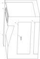
図1は実施例1のタンデム方式のカラー画像形成装置の全体を示す構成図である。タンデム方式のカラー画像形成装置はイエロー(Y)、マゼンタ(M)、シアン(C)、ブラック(K)の4色のトナーを重ねあわせることでフルカラー画像を出力できるように構成されている。符号の添え字Y,M,C,Kは各色を表す。なお、特定の色について説明する場合を除き、添え字Y,M,C,Kを省略する。各色の画像を形成するために、レーザスキャナ11とカートリッジ12が備えられている。カートリッジ12は、図中矢印の方向に回転する感光ドラム13と、感光ドラム13に接するように設けられたドラムクリーナ14、帯電ローラ15、及び現像ローラ16、現像ローラ16に供給するトナーを格納するトナー容器6から構成されている。各色の感光ドラム13には中間転写ベルト17が接して設けられ、この中間転写ベルト17を挟み、対向するように1次転写ローラ18が設置されている。また、記録材である用紙21は、カセット22に格納される。用紙21の搬送路には給紙ローラ25、搬送ローラ26、レジストレーションローラ(以下、レジローラという)27が設けられている。レジローラ27の用紙21の搬送方向の下流側近傍には、レジストレーションセンサ(以下、レジセンサという)28が設けられている。中間転写ベルト17と接するように2次転写ローラ29、そして2次転写ローラ29の搬送方向の下流側に定着器30、排出ローラ59が設置されている。排出ローラ59の近傍には、排出部紙有無センサ53が設けられている。
[Image forming apparatus]
FIG. 1 is a diagram showing the overall configuration of a tandem type color image forming apparatus according to the first embodiment. The tandem type color image forming apparatus is configured to output a full color image by superimposing four color toners, namely, yellow (Y), magenta (M), cyan (C), and black (K). The suffixes Y, M, C, and K of the reference symbols represent the respective colors. The suffixes Y, M, C, and K are omitted except when describing a specific color. A laser scanner 11 and a cartridge 12 are provided to form an image of each color. The cartridge 12 is composed of a photosensitive drum 13 that rotates in the direction of the arrow in the figure, a drum cleaner 14 that is provided in contact with the photosensitive drum 13, a charging roller 15, a developing roller 16, and a toner container 6 that stores the toner to be supplied to the developing roller 16. An
次に電子写真プロセスについて説明する。カートリッジ12内の暗所にて、感光ドラム13表面を帯電ローラ15で均一に帯電させる。次にレーザスキャナ11により画像データに応じて変調したレーザ光を感光ドラム13表面に照射し、レーザ光が照射された部分の帯電電荷が除去される。これにより、感光ドラム13表面に静電潜像が形成される。現像ローラ16では帯電したトナーを静電潜像に付着させることで、各色のトナー画像を感光ドラム13表面に形成する。そして各感光ドラム13表面上に形成されたトナー画像を1次転写ローラ18により中間転写ベルト17に順次重ね合わせるように転写する。
Next, the electrophotographic process will be described. In a dark place inside the cartridge 12, the surface of the photosensitive drum 13 is uniformly charged by the charging roller 15. Next, the laser scanner 11 irradiates the surface of the photosensitive drum 13 with laser light modulated according to image data, and the charged charge is removed from the area irradiated with the laser light. This forms an electrostatic latent image on the surface of the photosensitive drum 13. The developing roller 16 attaches charged toner to the electrostatic latent image, forming a toner image of each color on the surface of the photosensitive drum 13. The toner images formed on the surface of each photosensitive drum 13 are then transferred by the primary transfer roller 18 to the
一方、カセット22内の用紙21は給紙ローラ25により搬送され、搬送ローラ26により、用紙21がレジローラ27へ搬送される。次に中間転写ベルト17上のトナー画像をレジローラ27で搬送された用紙21上に2次転写ローラ29で転写する。最後に用紙21上の未定着のトナー画像は定着器30により定着され、排出ローラ59により、画像形成装置外に排出される。排出ローラ59の近傍には、排出ローラ59から排出された用紙の有無を検知するための排出部紙有無センサ53が設けられている。
Meanwhile, the
また、本体1は、制御基板60、残量検知手段であるトナー残量検知部62、表示部50を有している。制御基板60には、本体1の制御を行うための制御手段である制御部61が搭載されている。制御部61は、用紙21の搬送に関わる駆動源の制御や画像形成に関する制御等、本体1の動作を一括して制御する。制御部61は、記憶部(不図示)を有しており、例えば工場出荷時等に予め機種情報が記憶部に記憶されているものとする。トナー残量検知部62Y、62M、62C、62Kは、トナー容器6Y、6M、6C、6K内のトナー残量を検知するためのユニットである。表示部50は、本体1からの情報をユーザに報知するための表示器である。また、表示部50は、例えばオペレーションパネルであり、情報の表示に加え、情報の入力を行うことも可能である。
The
[カートリッジの装着構成]
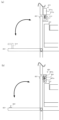
次に図2、図3を用いて実施例1のカートリッジ12の装着構成について説明する。図2、図3は、カートリッジ12を本体1に対し着脱可能な画像形成装置としてのプリンタの模式的斜視図である。カートリッジ12は、画像形成装置の本体1に対して脱着することにより交換可能であるユニットの一例であり、新品のユニットが本体1に装着されて使用が進み、やがて交換の時期(以下、寿命という)になると交換される。交換の時期とは、そのユニットを用いて画像形成を行った場合に、所定の画質等を維持することができなくなった時期等である。図2は、カートリッジ12の交換のために本体1に設けられた開口部を開閉する第1のドア40(以下、ドア40という)が閉塞状態(閉状態)にあるときの図である。ここで、ドア40は、カートリッジ12を本体1内部から取り出すために、カートリッジ12にアクセスするためのドアである。操作部材41は、ユーザがドア40を操作し開閉するための部材である。第2のドア42(以下、ドア42という)は、用紙21の搬送中に用紙21が詰まった場合等に、滞留した用紙21を取り除くジャム処理を行うために、搬送路にアクセスするためのドアである。
[Cartridge installation configuration]
Next, the mounting configuration of the cartridge 12 of the first embodiment will be described with reference to Figs. 2 and 3. Figs. 2 and 3 are schematic perspective views of a printer as an image forming apparatus in which the cartridge 12 can be detachably attached to the
図3(a)は、ドア40が開放状態(開状態)にあるときの図である。図2の状態で操作部材41を操作して図3(a)中矢印方向にドア40を動かすことによりドア40部分が開放される。ここで、ロック部材43Y、43M、43C、43Kは、それぞれカートリッジ12Y、12M、12C、12Kの取り出しをロックするための部材である。規制手段であるロックピン44Y、44M、44C、44Kは、それぞれ規制手段であるロック部材43Y、43M、43C、43Kの位置を規制するためのピンである。ロックピン44は、ソレノイド(不図示)により凸状態、凹状態を切り替えることが可能である。凸状態とは、ロックピン44がロック部材43よりも画像形成装置の手前側に突出した状態、凹状態とは、ロックピン44がロック部材43側に突出していない状態である。ここで、ロックピン44が凸状態になっているときに、カートリッジ12を取り出せないように(取り出し禁止)カートリッジ12のロックが実施されている規制状態(以下、ロック実施状態という)の位置にロック部材43が固定される。これによりユーザがカートリッジ12を取り出すことができない状態となる。
Figure 3(a) is a diagram showing the
図3(b)は、ロックピン44Yが凹状態を示す図であり、この場合、ロック部材43Yはカートリッジ12を取り出すことが可能(取り出し可能)となる位置(以下、取り出し可能位置という)に回転して移動することが可能となる。図3(b)は、イエローのカートリッジ12Yのロックが解除された解除状態(以下、ロック解除状態という)である。ユーザはカートリッジ12Yを図3(b)中濃い矢印方向に引き出すことで、カートリッジ12Yを本体1から取り出すことができる。図3(a)に示すように、この構成では、ドア40が開放状態となっただけではカートリッジ12を本体1から取り出すことはできない。図3(b)に示すように、ドア40が開かれた状態で、かつ、ロックピン44が凹状態の場合に、カートリッジ12は画像形成装置の正面方向(矢印方向)に取り出すことが可能となる。
Figure 3(b) shows the
ロックピン44Yは、後述の制御部61により制御され、制御部61は、カートリッジ12の取り出しを許可する状態(以下、取り出し許可という)と、取り出しを禁止する状態(以下、取り出し禁止という)とを切り替える構成となっている。
The
[制御構成]
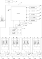
図4は制御構成のブロック図である。制御部61はCPU等で構成され、カートリッジ12の情報管理、カートリッジ12の寿命管理、及び、ロックの実施とロックの解除を切り替える制御を行っている。管理制御部202は、ROM、RAMを内蔵したワンチップマイクロコンピュータ(不図示)を有し、プリンタエンジンの各部の動作を管理する制御を行う。用紙搬送制御部203は、用紙21を給紙するための給紙ローラ25の駆動や、搬送するための搬送ローラ26の回転、停止を管理制御部202の指示に従って行う。高電圧制御部204は、帯電、現像、転写の各高電圧の出力制御を管理制御部202の指示に基づき行う。光学系制御部205は、レーザスキャナ11が有するスキャナモータ(不図示)の駆動/停止、レーザの点滅を管理制御部202の指示に従って行う。センサ入力制御部206は、レジセンサ28や排出部紙有無センサ53により検知した情報(検知結果)を管理制御部202に出力する。定着温度制御部207は、定着器30の温度を管理制御部202の指定した温度に制御する。イニシャル制御部208は、電源オン直後や緊急停止後の復帰処理(後述するイニシャル処理)を行う。イニシャル制御部208は、カートリッジ12の状態を検知する処理、後述する残留紙の検知処理、中間転写ベルト17のクリーニング処理等を行う。電源制御部209は、電源オン時又は電源オフ時、後述する省電力モードへの移行時又は省電力モードからの復帰時に、各制御部で必要な電力を供給したり、電力の供給を停止したりする。ロック制御部210は、カートリッジ12の情報管理、カートリッジ12の寿命管理を行う。ロック制御部210は、更に、ロック条件判断制御部230とロック解除条件判断制御部220とを有する。ロック条件判断制御部230は、ロックを実施する条件を満たしているか否かの判断と消耗品に対するロックの実施とを行う。ロック解除条件判断制御部220は、ロックを解除する条件を満たしているか否かの判断とロックの解除とを行う。ロック条件判断制御部230及びロック解除条件判断制御部220を有するロック制御部210は、ロックを実施するか否か、又はロックを解除するか否かの判断を行う判断手段として機能する。
[Control configuration]
FIG. 4 is a block diagram of the control configuration. The
カートリッジ12は、消耗品従属情報を記憶する従属情報記憶部70、及び消耗品寿命情報を記憶する寿命情報記憶部71を有する。消耗品従属情報は、例えば、カートリッジ12毎に一意に決定されたシリアルナンバー等を示す情報である。消耗品寿命情報は、例えば、カートリッジ12それぞれの寿命を示す情報である。従属情報記憶部70及び寿命情報記憶部71は、それぞれカートリッジ12が本体1に装着されたときに、制御部61のロック制御部210と接続される。
The cartridge 12 has a dependent information storage unit 70 that stores consumable dependent information, and a life information storage unit 71 that stores consumable life information. The consumable dependent information is, for example, information indicating a serial number uniquely determined for each cartridge 12. The consumable life information is, for example, information indicating the life of each cartridge 12. The dependent information storage unit 70 and the life information storage unit 71 are each connected to the
第1の記憶手段である消耗品情報記憶部72は、本体1に配置され、従属情報記憶部70及び寿命情報記憶部71の内容を記憶するための不揮発性の記憶手段である。消耗品情報記憶部72は、カートリッジ12が交換されたことを検知するために使用される。表示部50は、プリンタの状態(例えば、プリント可能状態や、カートリッジ12が寿命に到達したこと等)や、カートリッジ12の交換作業のオペレーションをユーザに報知するために用いられる。また、表示部50は、例えばタッチパネル等の機能も有し、ユーザが表示部50に表示された画面の所定の部分をタッチすることにより、所定の情報を入力したり設定したりすることが可能である。
The consumables
[消耗品従属情報及び消耗品寿命情報]
表1に第2の記憶手段である従属情報記憶部70Yに記憶されている内容を示す。表2に第2の記憶手段である寿命情報記憶部71Yに記憶されている内容を示す。表1、表2は、1列目に各項目、2列目に各項目に対応する値を格納した表である。従属情報記憶部70Yの記憶内容は、カートリッジ12毎に固有のシリアルナンバー(以下、シリアルNoとする)、カートリッジ12が使用される画像形成装置の機種情報、及びカートリッジ12の色を示すカートリッジ色情報である。この記憶内容は、制御部61(詳細には、ロック制御部210)により更新されることはない。例えば、イエローの従属情報記憶部70Yには、シリアルNoは「12345」、機種情報は「LBPXXXX」、カートリッジ色情報は「Y」という情報が記憶されている。
[Consumable Dependent Information and Consumable Life Information]
Table 1 shows the contents stored in the subordinate

寿命情報記憶部71Yには、感光ドラム13Yの寿命判断回転時間、感光ドラム13Yの回転積算時間が保持されている。感光ドラム13Yの回転積算時間は、画像形成装置の動作中の感光ドラム13の回転中に積算され、随時更新される。制御部61は、寿命判断回転時間及び回転積算時間の値を使用して、感光ドラム13Yの回転時間に係る残りの寿命を算出する。例えば、表2には、感光ドラム13Yの寿命判断回転時間は10000sec(秒)、回転積算時間は6000secと記憶されている。このため、使用量を%で表すと6000/10000×100=60%となり、感光ドラム13Yの残りの寿命(以下、残寿命という)は40%(=100%-60%)となる。
The life

寿命情報記憶部71Yには、感光ドラム13Yの寿命判断回転距離、感光ドラム13Yの回転積算距離が保持されている。感光ドラム13Yの回転積算距離は、画像形成装置の動作中の感光ドラム13の回転中に積算され、随時更新される。制御部61は、寿命判断回転距離及び回転積算距離の値を使用して、感光ドラム13Yの回転距離に係る残寿命を算出する。例えば、表2には、感光ドラム13Yの寿命判断回転距離は5000m(メートル)、回転積算距離は3500mと記憶されている。このため、使用量を%で表すと3500/5000×100=70%となり、感光ドラム13Yの残寿命は30%(=100%-70%)となる。
The life
また、表2のトナー容器6Y残量は、トナー残量検知部62Yによって検知されたトナー容器6Y内のトナー残量であり、随時記憶される。一般的な技術として、トナー残量は、レーザスキャナ11Y、11M、11C、11Kにより形成される画像の画素数を積算して計算される。なお、トナー残量は他の方法で求めてもよい。表2の中で、回転積算時間を用いて求められた残寿命、回転積算距離を用いて求められた残寿命、及びトナー残量、の3つの残量(残寿命)のうち、最も小さい値となったものをカートリッジ12Yの残量とする。なお、3つの残寿命の中で最も小さい値となった情報を、以下、最小寿命情報という。
The remaining amount of
表2の例では、回転積算時間からは残寿命が40%、回転積算距離からは残寿命が30%、トナー残量は25%とそれぞれ求められる。このことから、制御部61は、カートリッジ12Yの残寿命(最小寿命情報)を25%とする。このように、制御部61は、カートリッジ12の寿命情報記憶部71に記憶された、異なる手段によって求めた複数の残寿命の中から最小寿命情報を取得し、取得した最小寿命情報をカートリッジ12の寿命と判断する。なお、実施例1では、複数の情報、具体的には回転積算時間、回転積算距離及びトナー残量に基づいてカートリッジ12の寿命を判断した。しかし、例えば1つの情報、具体的には回転積算時間、回転積算距離及びトナー残量のいずれか1つに基づいてカートリッジ12の寿命を判断してもよい。また、カートリッジ12の寿命と相関のある情報であれば他の情報を用いてもよい。
In the example of Table 2, the remaining life is calculated as 40% from the cumulative rotation time, 30% from the cumulative rotation distance, and 25% remaining toner. Based on this, the
表2のカートリッジ12Yロック解除残量(以下、ロック解除残量という)は、カートリッジ12Yの残量がこの値以下となった場合にロック機構を解除するための残量の設定値(以下、残量設定値という)である。カートリッジ12Yの残寿命がロック解除残量以下となった場合に、制御部61はロック機構の解除を行う。表2の例では、制御部61は、最小寿命情報が5%以下となった場合に、ロック機構の解除を行う。なお、他の色についても同様であり、説明を省略する。制御部61が最小寿命情報とロック解除残量とに基づきカートリッジ12の交換時期と判断してロック機構を解除した場合を、以下、ロック機構解除という。
The
[消耗品情報記憶部]
表3に消耗品情報記憶部72に記憶される情報を示す。消耗品情報記憶部72には、各色カートリッジ12の各記憶部(70、71)に記憶された情報から選択した情報が記憶される。ここでは、比較用のシリアルNo、各ロック機構のロック状態、及び最小寿命情報が記憶される。
[Consumables information storage unit]
Table 3 shows information stored in the consumable product

表3は、1列目に各色、2列目に各色に対する各項目、3列目に各項目に対応する値、がそれぞれ格納された表である。例えば、イエロー(Y)に関しては、シリアルNoは、従属情報記憶部70Yから読み出した、例えば「12345」との情報が格納されている。また、ロック状態は、制御部61がロック機構を制御したときの情報(「ロック実施」又は「ロック解除」)が格納され、例えば「ロック実施」との情報が格納されている。更に、最小寿命情報は、寿命情報記憶部71Yから読み出した、例えば「25%」との情報が格納されている。
Table 3 is a table in which the first column stores each color, the second column stores each item for each color, and the third column stores the value corresponding to each item. For example, for yellow (Y), the serial number is stored as "12345" read from the subordinate
[画像形成中のロック機構の実施、解除の制御]
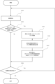
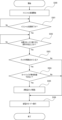
ここで、制御部61によるロック機構の処理方法を、図5及び図6のフローチャートを用いて説明する。図5のフローチャートは、画像形成中に、カートリッジ12の残寿命がロック解除残量以下(所定値以下)になった場合に、ロック機構を解除する、ロック機構解除処理の流れを示したものである。
[Control of activation and deactivation of lock mechanism during image formation]
Here, the method of processing the lock mechanism by the
制御部61は、画像形成の指示を受信すると、ステップ(以下、Sという)101以降の処理を開始する。S101で制御部61は、画像形成を行う。S102で制御部61は、画像形成中又は画像形成後に、ロック制御部210によって、寿命情報記憶部71に格納された表2の情報を参照することにより、少なくとも1つのカートリッジ12の残寿命がロック機構を解除する基準に到達したか否かを判断する。ここで、カートリッジ12の残寿命がロック機構を解除する基準に到達したとは、カートリッジ12が寿命に達したということである。S102で制御部61は、ロック制御部210により残寿命が基準に到達したと判断した場合、処理をS103に進める。S102で制御部61は、ロック制御部210により残寿命が基準に到達していないと判断した場合、処理をS106に進める。例えば、制御部61は、ロック制御部210によって、イエローのカートリッジ12Yに対して、表3の最小寿命情報から残寿命を25%と判断し、表2のロック解除残量から基準が5%と判断する。ロック制御部210は、これらを比較して、イエローのカートリッジ12Yは基準に到達していないと判断する。S103で制御部61は、ロック制御部210により残寿命がロック機構を解除する基準に到達したと判断したカートリッジ12のロックピン44を凹状態とし、ロックを解除する。例えば、イエローのカートリッジ12Yの残寿命がロック解除残量5%以下であった場合には、ロック制御部210はイエローのロックピン44Yを凹状態とする。
When the
S104で制御部61は、ロック制御部210によって、消耗品情報記憶部72の表3において、寿命に到達したと判断したカートリッジ12のロック状態に、ロックが解除された状態である情報(例えば、「ロック解除」等)を記憶する。S105で制御部61は、表示部50に、以下の情報を表示させる。制御部61は、カートリッジ12が寿命に到達したことを報知するとともに、寿命に到達したカートリッジ12を新しいカートリッジ(以下、新品カートリッジという)に交換するように促す表示(交換指示等)を行い、処理をS106に進める。S106で制御部61は、引き続き画像形成指示があるか否かを判断し、画像形成指示があると判断した場合、処理をS101に戻し、画像形成指示がないと判断した場合、処理を終了する。
In S104, the
このように、カートリッジ12が所定の寿命以下になった場合に、カートリッジ12のロックを解除する。カートリッジ12の寿命が残っている場合に誤って別のカートリッジ、例えば新品カートリッジに交換してしまい、不要なコストの発生を防ぐ構成となっている。 In this way, when the cartridge 12 reaches or falls below a predetermined lifespan, the lock on the cartridge 12 is released. This prevents the cartridge 12 from being accidentally replaced with another cartridge, for example a new cartridge, when there is still life left, resulting in unnecessary costs.
[電源オン時又はドアクローズ時のロック機構の実施の判断処理]
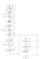
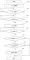
図6の説明を行う。図6は電源がオンされたとき(以下、電源オン時という)又はドア40が閉塞状態となったとき(以下、ドアクローズ時という)に制御部61により開始される処理を示すフローチャートである。図6のフローチャートは、電源オン時又はドアクローズ時にイニシャル処理(初期化処理)を開始し、イニシャル処理が完了したタイミングにおいて、ロック条件判断制御部230によりカートリッジ12のロックを実施する場合も含むフローチャートである。
[Determination process for lock mechanism implementation when power is turned on or door is closed]
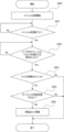
Fig. 6 will be described. Fig. 6 is a flowchart showing the process started by the
S110で制御部61は、イニシャル制御部208によってイニシャル処理を開始する。S111で制御部61は、イニシャル制御部208によってカートリッジ12の状態をチェックする処理(以下、カートリッジ状態チェック処理という)を開始する。イニシャル制御部208によって実施されるカートリッジ状態チェック処理は、従属情報記憶部70又は寿命情報記憶部71に記憶されている情報(表1、表2参照)を読み出し、読み出した情報に基づいてカートリッジ12の状態をチェックする処理である。S112で制御部61は、イニシャル制御部208によるカートリッジ状態チェック処理が終了したか否かを判断し、処理が終了していないと判断した場合、処理をS112に戻し、処理が終了したと判断した場合、処理をS113に進める。S113で制御部61は、S111でチェックしたカートリッジ12の寿命情報(消耗品寿命情報)を表示部50に表示しユーザに報知する。
In S110, the
S114で制御部61は、イニシャル制御部208によって残留紙検知処理を開始する。ここで、残留紙検知処理とは、装置内部に残留している用紙があるかどうかを確認するために、搬送路上に配置されたローラを一定時間回転させる処理である。ローラを回転させている間、イニシャル制御部208は搬送路上に配置された少なくとも1つのセンサ(不図示)によって、搬送路上に残留した用紙21(以下、残留紙という)の有無(有り・無し)を監視する。また、残留紙検知処理とは、センサが残留紙の“有り”を検知した場合に、イニシャル制御部208は搬送路上に配置された用紙Pを搬送するための少なくとも1つのローラを駆動し、残留紙を機外に排出する処理を含む。
At S114, the
S115で制御部61は、イニシャル制御部208による残留紙検知処理が終了したか否かを判断し、処理が終了していないと判断した場合、処理をS115に戻し、処理が終了したと判断した場合、処理をS116に進める。S116で制御部61は、S114で実施した残留紙検知処理によって機内に残留紙がないか否かを判断する。S116で制御部61は、機内に残留紙がないと判断した場合、処理をS117に進め、機内に残留紙があると判断した場合、処理を終了する。なお、制御部61は、機内に残留紙があると判断した場合は、例えば表示部50に機内に残留紙があること(すなわち、ジャムであること)を表示させて、ユーザに報知した後で処理を終了してもよい。
In S115, the
S117で制御部61は、イニシャル制御部208によってクリーニング処理を開始する。ここで、クリーニング処理とは、次のような処理をいう。まず、中間転写ベルト17や感光ドラム13を駆動し、感光ドラム13から中間転写ベルト17にトナー像を転写するときとは逆極性の電圧を印加して、中間転写ベルト17上に残っているトナーを感光ドラム13に転写する(以下、逆転写という)処理を含む。そして、逆転写されて感光ドラム13上に移動したトナーをドラムクリーナ14によって廃トナー容器に格納する処理を含む。S118で制御部61は、イニシャル制御部208によるクリーニング処理が終了したか否かを判断し、クリーニング処理が終了していないと判断した場合、処理をS118に戻し、クリーニング処理が終了したと判断した場合、処理をS119に進める。S119で制御部61は、イニシャル制御部208によるイニシャル処理を終了する。
In S117, the
S120で制御部61は、ロック制御部210によって、消耗品情報記憶部72に記憶されている情報(表3の「ロック状態」)を読み出し、読み出した情報に基づいて消耗品(ここでは、カートリッジ12)のロックが解除されているか否かを判断する。S120で制御部61は、ロックが解除されていない、すなわち、ロックが実施されている状態(施錠状態)であると判断した場合、処理を終了する。S120で制御部61は、ロックが解除されていると判断した場合、処理をS121に進める。S121で制御部61は、ロック制御部210によって、消耗品情報記憶部72に記憶されている情報(表3の「最小寿命情報」)に基づいて、消耗品(カートリッジ12)が寿命に到達していないか否かを判断する。ここで、イニシャル処理が終了したタイミングではカートリッジ状態チェック処理も終了しているため、既に消耗品情報記憶部72に記憶されている情報が更新されている。S121で制御部61は、消耗品(カートリッジ12)が寿命に到達していると判断した場合、カートリッジ12のロックが解除された状態を維持したまま、処理を終了する。S121で制御部61は、消耗品(カートリッジ12)が寿命に到達していないと判断した場合、処理をS122に進める。S122で制御部61は、ロック制御部210によって消耗品(カートリッジ12)のロックを実施する。実施例1では、ドアクローズ時にカートリッジ12のロックが解除されている状態であっても、カートリッジ12が寿命に到達している場合、すなわち、交換作業が完了していない場合には、カートリッジ12のロックは実施されない。
In S120, the
以上説明したように、制御部61は、電源オン時又はドアクローズ時に開始されるイニシャル処理を実行し、イニシャル処理が完了したタイミングで、ロックを実施するか否かの判断を行う。これにより、制御部61は、寿命に到達したカートリッジ12の交換作業が完了したと判断することができる。また、交換作業が完了していないにもかかわらずドア40が閉塞状態となっている場合には、カートリッジ12のロックを解除した状態を維持することができる。
As described above, the
なお、上記の実施例1において、イニシャル処理として、カートリッジ状態チェック処理、残留紙検知処理、クリーニング処理を実行する場合について説明したが、これに限定されない。イニシャル処理として、例えば他にカートリッジシール引き処理を実行してもよい。カートリッジシール引き処理とは、新品カートリッジに交換された場合に、カートリッジに装着されたシール部材を除去する処理のことである。ここで、シール部材とは、カートリッジに格納されているトナーが輸送時にこぼれないようにトナーを密封するための部材である。
In the
また、図6のフローチャートにおいては、複数のイニシャル処理を順番に実行する制御について説明したが、これに限定されない。複数のイニシャル処理を並行して実行してもよい。例えば、カートリッジ状態チェック処理を実行している間に、並行して残留紙検知処理等を実行してもよい。この場合、カートリッジ状態チェック処理よりも早いタイミングで他のイニシャル処理が終了したとしても、全体としてのイニシャル処理が終了するまではカートリッジ12のロックを実施しないように制御する。 In addition, in the flowchart of FIG. 6, the control for executing multiple initial processes in sequence has been described, but this is not limiting. Multiple initial processes may be executed in parallel. For example, a residual paper detection process or the like may be executed in parallel while a cartridge status check process is being executed. In this case, even if another initial process is completed earlier than the cartridge status check process, control is performed so that the cartridge 12 is not locked until the entire initial process is completed.
実施例1では、イニシャル処理が終了した後にロックを実施するが(図6 S119~S122)、この判断のタイミングとしては、次のようなタイミングであってもよい。すなわち、イニシャル処理の途中やイニシャル処理が終了してから所定時間が経過した後(例えば、省電力モード移行前のタイミング等)であってもよい。なお、ここでいうイニシャル処理とは、カートリッジ状態チェック処理以外のイニシャル処理のことであって、少なくともカートリッジ状態チェック処理が終了するまではカートリッジ12のロックを実施しないように制御する。 In the first embodiment, the lock is performed after the initial process is completed (S119 to S122 in FIG. 6), but the timing of this determination may be the following. That is, it may be during the initial process or after a predetermined time has elapsed since the initial process is completed (for example, before switching to power saving mode). Note that the initial process referred to here is an initial process other than the cartridge state check process, and the cartridge 12 is controlled not to be locked at least until the cartridge state check process is completed.
実施例1では、複数のカートリッジを有するカラー画像形成装置のロック機構について説明したが、カートリッジを1つしか有しないモノクロ画像形成装置においても同様の制御が可能である。以上、実施例1によれば、交換可能なユニットのロック機構に関するユーザビリティを向上させることができる。また、実施例1では、図2、図3に示す構成を用いて説明したが、後述する実施例2の図7、図8の構成や実施例3の図11の構成を用いた場合でも同等の制御を実施することが可能である。 In the first embodiment, the locking mechanism of a color image forming apparatus having multiple cartridges is described, but similar control is also possible in a monochrome image forming apparatus having only one cartridge. As described above, according to the first embodiment, it is possible to improve the usability of the locking mechanism of a replaceable unit. In addition, in the first embodiment, the configuration shown in Figs. 2 and 3 is used, but it is possible to implement the same control even when using the configuration shown in Figs. 7 and 8 of the second embodiment, which will be described later, or the configuration shown in Fig. 11 of the third embodiment.
以上、実施例1によれば、消耗品の交換の際のユーザビリティを向上させることができる。 As described above, according to the first embodiment, usability when replacing consumables can be improved.
実施例2では、カートリッジ12Y、12M、12C、12K毎にカートリッジ12にアクセスするためのドアを有する。これらのドアにカートリッジ12の取り出しを制限するドアロック機構を設け、更に各ドアに、ドア開閉を検知するセンサを設ける。なお、実施例1で説明した内容については、同一番号を付して説明を省略する。
In the second embodiment, each of the
[カートリッジとドアの構成]
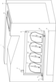
図7、図8を用いて実施例2のカートリッジ12の装着構成及びドア構成について説明する。図7は、カートリッジ12を画像形成装置の本体1に対し着脱可能な画像形成装置としてのプリンタの模式的斜視図である。実施例2では、ドアは、カートリッジ12に対応して複数設けられている。図7は、カートリッジ12毎に設けられたドア45Y、45M、45C、45Kのうち、ドア45Yが開状態、ドア45M、45C、45Kが閉状態にあるときの図である。ここで、規制手段であるロックピン47は、それぞれドア45の開状態への動きを規制する。規制手段であるロック部材51はそれぞれロックピン47と対になり、ドア45を閉状態に固定する部材である。
[Cartridge and door configuration]
The mounting configuration of the cartridge 12 and the door configuration of the second embodiment will be described with reference to Figs. 7 and 8. Fig. 7 is a schematic perspective view of a printer as an image forming apparatus in which the cartridge 12 can be detachably attached to the
図8(a)に示すように、ロックピン47Yが凸状態になっているときに、ロックピン47Yとロック部材51Yとが嵌合し、ドア45Yを閉状態に固定する。ドア45Yを閉状態に固定することにより、ユーザによるカートリッジ12Yの取り出しが禁止される。ロックピン47は、後述の制御部81(具体的には、ロック制御部211)により制御され、各ドア45をそれぞれ開状態(破線)にすることを許可すること(以下、開許可という)と、閉状態(実線)を固定とすること(以下、閉固定という)とを切り替える。
As shown in FIG. 8(a), when the
また、第2の検知手段である開閉センサ48Yは、ドア45Yの開閉状態を検知する。部材49Yはドア45Yの開閉状態を開閉センサ48Yによって検知するための部材である。なお、図7では、ドア45M、45C、45Kが閉状態となっているため、第2の検知手段である開閉センサ48M、48C、48K及び部材49M、49C、49Kは不図示である。また、操作部材46M、46C、46Kは、それぞれドア45M、45C、45Kを操作するための部材である。なお、ドア45Yが開状態となっているため、操作部材46Yは不図示である。
The second detection means, the open/
図8(a)は、カートリッジ12Yと、ドア45Yのドアロック構成を示す、ロックピン47Yの位置における断面図である。ロックピン47Yは、ロックピン本体47Yaと、ロックピン本体47Yaに対して内部に収納された状態又は外部に突出した状態となる部材47Ybとを有する。ドア45Yが閉状態のとき、ロックピン47Yの部材47Ybを下方向に動作させて突出させると、ロックピン47Yの部材47Ybがロック部材51Yに嵌合する。ロックピン47Yの部材47Ybとロック部材51Yとの嵌合により、ドア45Yは、閉状態に固定(閉固定)される。一方、ロックピン47Yの部材47Ybを上方向に動作させてロックピン本体47Ya内に収容すると、ドア45Yのロックが解除されて開許可となり、操作部材46Yを操作してドア45Yを開状態とすることができる。
Figure 8(a) is a cross-sectional view showing the
[ドアの開閉検知]
図8(b)は、カートリッジ12Yとドア45Yの開閉検知構成を示す、開閉センサ48Yの位置における断面図である。開閉センサ48Yは、例えばフォトインタラプタで構成される。例えば、開閉センサ48Yは、光を出射する発光部48Yaと、発光部48Yaから出射された光を受光する受光部48Ybと、を有する。部材49Yが開閉センサ48Yに挿入されると、発光部48Yaから出射された光は部材49Yによって遮光されるため、受光部48Ybによって受光されず、開閉センサ48Yはドア45Yの閉状態を検知する。一方、部材49Yが開閉センサ48Yに挿入されていないときは、発光部48Yaから出射された光は部材49Yによって遮光されることなく受光部48Ybによって受光され、開閉センサ48Yはドア45Yの開状態を検知する。開閉センサ48Yによって検知された情報(検知結果)は、後述の制御部81のロック制御部211に出力される。
[Door opening/closing detection]
8B is a cross-sectional view showing the open/close detection structure of the
[制御構成]
図9は実施例2の制御構成のブロック図である。制御部81はCPU等で構成され、カートリッジ12の情報管理、カートリッジ12の寿命管理、及び、ドアロック機構の出力制御、開閉センサ48の検知を行っている。制御部81は、ロック解除条件判断制御部220及びロック条件判断制御部231を有するロック制御部211を有する。制御部81は、ロック条件判断制御部231及びロック解除条件判断制御部220によるロックピン47Y、47M、47C、47Kの制御(部材47Ybの突出と収納)及び、開閉センサ48Y、48M、48C、48Kによる検知を行っている。他の構成については実施例1と同様であり、同じ構成には同じ符号を付し、説明を省略する。ロック解除条件判断制御部220によるロック解除の処理に関しては実施例1の図5で説明しているので省略する。
[Control configuration]
FIG. 9 is a block diagram of the control configuration of the second embodiment. The
[電源オン時又はドアクローズ時のロック機構の実施の判断処理]
実施例2では、イニシャル処理後に印刷動作(印刷処理)(以下、プリントという)が実行され、プリントが正常に完了した後に、ロック条件判断制御部231によりロックを実施するか否かの判断を行う例について図10のフローチャートを用いて説明する。図10の処理も、制御部81によって、電源オン時又はドアクローズ時に実行される。なお、S210の処理は図6のS110と同じ処理であり説明を省略する。また、S211の処理は、図6のS111からS119までの処理を1つの判断処理として記載したものであるため、説明を省略する。
[Determination process for lock mechanism implementation when power is turned on or door is closed]
In the second embodiment, a printing operation (printing process) (hereinafter referred to as printing) is executed after the initial process, and after the printing is normally completed, the lock condition
S212で制御部81は、プリントが実行されたか否かを判断する。S212で制御部81は、プリントが実行されていないと判断した場合、処理をS212に戻し、プリントが実行されたと判断した場合、処理をS213に進める。S213で制御部81は、プリント処理を開始する。S214で制御部81は、プリント処理が終了したか否かを判断する。S214で制御部81は、プリント処理が終了していないと判断した場合、処理をS214に戻し、プリント処理が終了したと判断した場合、処理をS215に進める。なお、S215~S217の処理は、図6のS120~S122の処理と同様の処理であるため、説明を省略する。実施例2においても、ドアクローズ時にドア45のロックが解除されている状態であっても、カートリッジ12が寿命に到達している場合、すなわち、交換作業が完了していない場合には、ドア45のロックは実施されない。
In S212, the
以上説明したように、実施例2では、イニシャル処理が終了した後にプリントが実行され、プリントが終了した後にドア45のロックを実施するか否かの判断を行う。これにより、制御部81は寿命に到達したカートリッジ12の交換作業が完了したと判断することができる。
As described above, in the second embodiment, printing is performed after the initial process is completed, and after printing is completed, a determination is made as to whether or not to lock the door 45. This allows the
実施例2では、プリント終了後に消耗品のロックを実施するか否かの判断を行っているが、判断のタイミングとしては、次のようなタイミングでもよい。例えば、プリント開始時やプリント中、プリントが終了してから所定時間が経過した後(例えば省電力モード移行前のタイミング等)に判断を行うことも可能である。また、プリントが終了した後、排出部紙有無センサ53により、排出された用紙21が取り除かれたことを検知した場合に、制御部81(具体的にはロック制御部211のロック条件判断制御部231)は判断を行うことも可能である。また、実施例2では、図7、図8の構成で説明したが、実施例1の図2、図3の構成、及び後述する実施例3の図11の構成においても同等の制御が可能である。
In the second embodiment, a determination is made as to whether or not to lock the consumables after printing is completed, but the timing of the determination may be as follows. For example, the determination may be made at the start of printing, during printing, or after a predetermined time has elapsed since printing was completed (for example, before switching to power saving mode). In addition, after printing is completed, if the discharge section
以上、実施例2によれば、消耗品の交換の際のユーザビリティを向上させることができる。 As described above, according to the second embodiment, usability when replacing consumables can be improved.
実施例3では、カートリッジ12Y、12M、12C、12Kに対し、共通の1つのドアで構成され、ドアにカートリッジの取り出しを制限するロック機構を設ける。更にドアに、ドアの開閉を検知するセンサを設けた構成における動作を示す。なお、実施例1、実施例2で説明した内容については、同一番号を付して説明を省略する。
In the third embodiment, a single common door is used for
[ドアの構成]
図11を用いて実施例3のカートリッジ12の装着構成及びドア構成について説明する。図11は、カートリッジ12を画像形成装置の本体1に対し着脱可能な画像形成装置としてのプリンタの模式的斜視図である。図11は、カートリッジ12全てに対して設けられた1つのドア52が開状態にあるときの図である。ここでロックピン47は、ドア52の開状態への動きを規制するピンである。ロック部材51はロックピン47と対になり、ドア52を閉状態に固定する部材である。ここで、ロックピン47が凸状態になっているときに、ロックピン47とロック部材51とが嵌合し、ドア52を閉状態に固定する。ドア52を閉状態に固定することにより、カートリッジ12Y、12M、12C、12Kの取り出しが禁止される。ロックピン47は、後述の制御部91(具体的にはロック制御部212)により制御され、ドア52の開許可、閉固定を切り替える。
[Door configuration]
The mounting configuration and door configuration of the cartridge 12 of the third embodiment will be described with reference to FIG. 11. FIG. 11 is a schematic perspective view of a printer as an image forming apparatus in which the cartridge 12 can be attached to and detached from the
また、第1の検知手段である開閉センサ48は、ドア52の開閉状態を検知するセンサであり、部材49はドア52の開閉状態を開閉センサ48によって検知するための部材である。ドア52が図11に示す状態で、カートリッジ12を取り出すことが可能である。実施例3では、ドア52のロック機構がロック解除状態となったことで、カートリッジ12の交換が可能となる。このため、少なくとも1つのカートリッジ12が寿命に達した場合には、ドア52を開許可とする。なお、ドアロック構成及び開閉センサの構成については、実施例2と同様であり、説明を省略する。
The first detection means, the open/
[制御構成]
図12は実施例2の制御構成のブロック図である。制御部91はCPU等で構成され、カートリッジ12の情報管理、カートリッジ12の寿命管理、及び、ドア52のロック機構の出力制御、開閉センサ48の検知を行っている。制御部91は、ロック解除条件判断制御部222及びロック条件判断制御部232を有するロック制御部212を有する。制御部91のロック制御部212は、ロックピン47の出力制御及び、開閉センサ48によるドア52の検知を行っている。他の構成については実施例1、実施例2と同様であり、同じ構成には同じ符号を付して説明を省略する。
[Control configuration]
12 is a block diagram of the control configuration of the second embodiment. The
[ロック機構]
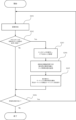
ここで、制御部91による、カートリッジ12のロック機構の解除処理方法を、図13を用いて説明する。図13のフローチャートは、画像形成中に、カートリッジ12の残量が所定値以下になった場合に、ロック解除条件判断制御部222によりドア52のロックを解除するロック機構解除処理を示したものである。
[Lock mechanism]
Here, a method of unlocking the lock mechanism of the cartridge 12 by the
制御部91は、画像形成の指示を受信するとS201以降の処理を実行する。S201で制御部91は、画像形成を行う。S202で制御部91は、画像形成中又は画像形成後に、ロック制御部212によって、少なくとも1つのカートリッジ12の寿命がドア52のロックを解除する基準の値に到達したか否かを判断する。S202で制御部91は、ドア52のロックを解除する基準に到達したと判断した場合、処理をS203に進める。S202で制御部91は、ロックを解除する基準に到達していないと判断した場合、処理をS206に進める。
When the
S203で制御部91は、ロック制御部212によりロックピン47を操作し、ドア52のロックを解除する。S204で制御部91は、ロック制御部212によって、消耗品情報記憶部72の表3において、寿命に到達したと判断した色のカートリッジ12のロック状態に、ロックが解除された状態である情報(例えば、「ロック解除」等)を記憶する。また、実施例3では、カートリッジ12の寿命情報記憶部71はロック情報を記憶する領域を有しており、ロック制御部212は、寿命に到達した色のカートリッジ12の寿命情報記憶部71にロック解除状態を記憶する。S205で制御部91は、表示部50にカートリッジ12の寿命到達を報知するとともに、寿命に到達した色のカートリッジ12を新品カートリッジに交換するように指示し、処理をS206に進める。S206で制御部91は、引き続き画像形成の指示があるか否かを判断する。S206で制御部91は、画像形成の指示があると判断した場合、処理をS201に戻し、画像形成の指示がないと判断した場合、画像形成動作を終了する。
In S203, the
[電源オン時又はドアクローズ時のロック機構の実施の判断処理]
実施例3では、イニシャル処理後に省電力状態である省電力モードに移行する際にロック条件判断制御部232によりロックを実施するか否かの判断を行う例について図14のフローチャートを用いて説明する。省電力モードでは、画像形成時よりも消費される電力が低い状態となる。実施例3の画像形成装置は、画像形成動作を行うために待機した状態であるスタンバイ状態に移行することが可能である。そして、実施例3の画像形成装置は、スタンバイ状態に移行してから所定の時間が経過した場合に省電力モードに移行する。図14の処理も、制御部91によって、電源オン時又はドアクローズ時に実行される。なお、S300の処理は図6のS110と同じ処理であり説明を省略する。また、S301の処理は、図6のS111からS119までの処理を1つの判断処理として記載したものであるため、説明を省略する。
[Determination process for lock mechanism implementation when power is turned on or door is closed]
In the third embodiment, an example of the lock condition
S302で制御部91は、省電力モードに移行する条件が成立したか否かを判断する。実施例3では、例えば省電力モードに移行する条件は、イニシャル処理が終了し、プリント指示を受信したらプリントを開始できる状態であるスタンバイ状態が1分間継続した場合とする。S302で制御部91は、省電力モードに移行する条件が成立していない、例えばスタンバイ状態が開始されてから1分が経過していないと判断した場合、処理をS302に戻す。S302で制御部91は、省電力モードに移行する条件が成立した、例えばスタンバイ状態が開始されてから1分が経過したと判断した場合、処理をS303に進める。なお、S303~S305の処理は、図6のS120~S122の処理と同様の処理であるため、説明を省略する。ただし、S303でロックが実施されている場合(No)、S304でカートリッジ12が寿命に到達している場合(No)、S305の処理の後は、S306の処理に進む。
In S302, the
S306で制御部91は、省電力モードに移行し、処理を終了する。実施例3においても、ドアクローズ時にドア52のロックが解除されている状態であっても、カートリッジ12が寿命に到達している場合、すなわち、交換作業が完了していない場合には、ドア52のロックは実施されない。
In S306, the
以上説明したように、実施例3では、イニシャル処理後に省電力モードに移行するときにロックを実施するか否かの判断を行う。これにより、制御部91は、寿命に到達したカートリッジ12の交換作業が完了したと判断することができる。実施例3では、省電力モードに移行するタイミングで消耗品のロックを実施するか否かの判断を行ったが、判断を行うタイミングとしては、次のようなタイミングであってもよい。例えば、省電力モードへ移行する途中や省電力モードへ移行してから所定時間が経過した後、また、省電力モードから復帰したときに判断を行うことも可能である。実施例3では、図11の構成で説明したが、実施例1の図2、図3の構成、及び実施例2の図7、図8の構成においても同等の制御が可能である。
As described above, in the third embodiment, a determination is made as to whether or not to lock the consumables when the power saving mode is entered after the initial process. This allows the
以上、実施例3によれば、消耗品の交換の際のユーザビリティを向上させることができる。 As described above, according to the third embodiment, usability when replacing consumables can be improved.
実施例4では、イニシャル処理後にオペレーションパネル等の表示部50に、交換作業が完了したかを確認するための確認画面を表示し、ユーザが表示部50に作業完了を設定したことに応じてロックを実施するか否かの判断を行う例について説明する。制御部の一例として図4の制御部61を主体として、以下説明する。表示部50に表示される確認画面は、例えば「交換作業が完了しましたか」等のメッセージが表示され、画面の所定の位置に「完了」を示す仮想のボタン(以下、仮想ボタンという)が表示されたもの等である。ユーザは、交換作業が完了した後に、表示部50に表示された所定の位置、例えば、仮想のボタン「完了」部分をタッチ(押下)する。これにより、制御部61は、交換作業が完了したことが設定されたと判断する。なお、構成に関しては、実施例1の図2、図3の構成、実施例2の図7、図8の構成、及び実施例3の図11の構成のどの構成においても同等の制御が可能である。
In the fourth embodiment, a confirmation screen for confirming whether the replacement work is completed is displayed on the
[電源オン時又はドアクローズ時のロック機構の実施の判断処理]
図15のフローチャートを用いて説明する。なお、S400の処理は図6のS110と同じ処理であり説明を省略する。また、S401の処理は、図6のS111からS119までの処理を1つの判断処理として記載したものであるため、説明を省略する。S402で制御部61は、ユーザが表示部50(オペレーションパネル等)を用いて交換作業が完了したことに応じた操作(例えば、上述した「完了」の仮想ボタンの押下)がなされたか否かを判断する。実施例4においては、制御部61は、イニシャル処理が終了したら、表示部50に上述した確認画面を表示し、ユーザが確認画面の所定の位置を押下すると、作業完了と判断する。
[Determination process for lock mechanism implementation when power is turned on or door is closed]
The flow chart of FIG. 15 will be used for explanation. The process of S400 is the same as S110 in FIG. 6, and explanation will be omitted. The process of S401 is a process in which the processes from S111 to S119 in FIG. 6 are described as one judgment process, and explanation will be omitted. In S402, the
S402で制御部61は、上述した操作がなされていないと判断した場合、処理をS402に戻し、上述した操作がなされたと判断した場合、処理をS403に進める。なお、S403~S405の処理は、図6のS120~S122の処理と同様の処理であるため、説明を省略する。実施例4においても、ドアクローズ時にカートリッジ12のロックが解除されている状態であっても、カートリッジ12が寿命に到達している場合、すなわち、交換作業が完了していない場合には、カートリッジ12のロックは実施されない。
If the
以上説明したように、実施例4では、表示部50に交換作業が完了したかを確認するための確認画面を表示し、ユーザが表示部50において、交換作業が完了したことに応じた操作を実行したときにロックを実施するか否かの判断を行う。これにより、制御部61は、寿命に到達したカートリッジ12の交換作業が完了したと判断することができる。
As described above, in the fourth embodiment, a confirmation screen for confirming whether the replacement work is completed is displayed on the
以上、実施例4によれば、消耗品の交換の際のユーザビリティを向上させることができる。 As described above, according to the fourth embodiment, usability when replacing consumables can be improved.
実施例5では、実施例1で説明した図2、図3の構成を用いて説明する。図2、図3に関しては実施例1で説明済みなので省略する。 In the fifth embodiment, the configurations shown in Figs. 2 and 3 described in the first embodiment will be used. As Figs. 2 and 3 have already been described in the first embodiment, they will not be described here.
[制御構成]
図16は実施例5の制御構成のブロック図である。制御部101はCPU等で構成され、カートリッジ12の情報管理、カートリッジ12の寿命管理、及び、ドア40のロック機構の出力制御、人感センサ54による検知を行っている。制御部101は、ロック解除条件判断制御部220及びロック条件判断制御部233を有するロック制御部213を有する。制御部101のロック制御部213は、ロックピン44の出力制御を行っている。人感センサ54は、例えば画像形成装置の正面に配置されている。画像形成装置の正面とは、例えば、ドア40が設けられている面をいう。人感センサ54は、画像形成装置周辺に人物が存在するか否かを検知し、検知結果を制御部101に出力する。他の構成については実施例1と同様である。ロック解除条件判断制御部220によるロック解除の処理に関しては実施例1の図5で説明しているので省略する。
[Control configuration]
FIG. 16 is a block diagram of the control configuration of the fifth embodiment. The
[電源オン時又はドアクローズ時のロック機構の実施の判断処理]
実施例5では、制御部101は、イニシャル処理後に人感センサ54によって画像形成装置の周辺に人物がいないことを検知した場合に、ロック条件判断制御部233によりロックを実施するか否かの判断を行う例について図17で説明する。図17の処理も、制御部101によって、電源オン時又はドアクローズ時に実行される。なお、S500の処理は図6のS110と同じ処理であり説明を省略する。また、S501の処理は、図6のS111からS119までの処理を1つの判断処理として記載したものであるため、説明を省略する。
[Determination process for lock mechanism implementation when power is turned on or door is closed]
In the fifth embodiment, an example will be described with reference to Fig. 17 in which the
S502で制御部101は、人感センサ54で人物を検知しているか否かを判断する。S502で制御部101は、人感センサ54により人物を検知していると判断した場合、処理をS502に戻し、人物を検知しなくなったと判断した場合、処理をS503に進める。なお、S502の判断処理において、制御部101は、人感センサ54により所定の時間、継続して人物を検知していない場合に、人物を検知しなくなったと判断するようにしてもよい。なお、S503~S505の処理は、図6のS120~S122の処理と同様の処理であるため、説明を省略する。実施例5においても、ドアクローズ時にドア40のロックが解除されている状態であっても、カートリッジ12が寿命に到達している場合、すなわち、交換作業が完了していない場合には、ドア40のロックは実施されない。
In S502, the
以上説明したように、実施例5では、制御部101は、イニシャル処理後に、人感センサ54の検知結果に基づき画像形成装置の周辺に人物がいないと判断した場合に、ロックを実施するか否かの判断を行う。これにより、制御部101は、寿命に到達したカートリッジ12の交換作業が完了したと判断することができる。実施例5では、図2、図3の構成で説明したが、実施例2の図7、図8の構成、及び実施例3の図11の構成においても同等の制御が可能である。
As described above, in the fifth embodiment, the
以上、実施例5によれば、消耗品の交換の際のユーザビリティを向上させることができる。 As described above, according to the fifth embodiment, usability when replacing consumables can be improved.
12 カートリッジ
40 ドア
44 ロックピン
61 制御部
210 ロック制御部
12
Claims (19)
装置本体と、
前記装置本体に対して脱着することにより交換可能であるユニットと、
回転体と、
前記ユニットを前記画像形成装置から取り出せないようにするための規制状態と、前記ユニットを前記画像形成装置から取り出すことができるようにするための解除状態に切り替わる規制手段と、
前記規制手段を前記解除状態から前記規制状態に切り替える切り替え手段を制御する制御手段と、
を備え、
前記ユニットが別のユニットに交換された場合に、前記記録材に対するプリント処理の開始前に、前記回転体を回転する回転動作が実行され、
前記回転動作が終了していない場合に前記規制手段が前記解除状態に維持され、前記回転動作が終了した後に前記規制手段が前記規制状態に切り替わるように、前記制御手段は前記切り替え手段を制御することを特徴とする画像形成装置。 An image forming apparatus for forming an image on a recording material,
A device body,
a unit that is replaceable by being detached from the device body;
A rotating body;
a restricting means for switching between a restricting state for preventing the unit from being removed from the image forming apparatus and a releasing state for allowing the unit to be removed from the image forming apparatus;
a control means for controlling a switching means for switching the restriction means from the release state to the restriction state;
Equipped with
when the unit is replaced with another unit, a rotation operation is performed to rotate the rotating body before a print process is started on the recording material ,
An image forming apparatus characterized in that the control means controls the switching means so that the regulating means is maintained in the released state when the rotation operation has not been completed, and the regulating means switches to the regulating state after the rotation operation has been completed.
前記ユニットに設けられ、前記ユニットに関する情報を記憶する第2の記憶手段と、
を備え、
前記制御手段は、前記第1の記憶手段及び前記第2の記憶手段に記憶された情報に基づいて、前記規制手段の状態を切り替えるように前記切り替え手段を制御することを特徴とする請求項2に記載の画像形成装置。 a first storage means for storing information indicating whether the restricting means is in the restricted state or the released state;
a second storage means provided in the unit for storing information relating to the unit;
Equipped with
3. The image forming apparatus according to claim 2, wherein the control means controls the switching means to switch the state of the regulating means based on the information stored in the first storage means and the second storage means.
前記制御手段は、前記回転動作が終了した後、前記省電力状態に移行する前に前記規制手段を前記規制状態に切り替えることを特徴とする請求項1から8のいずれか1項に記載の画像形成装置。 the image forming apparatus is capable of switching to a power saving state in which power consumption is lower than that during image formation;
9. The image forming apparatus according to claim 1, wherein the control unit switches the regulating unit to the regulating state after the rotation operation is completed and before the image forming apparatus transitions to the power saving state.
前記制御手段は、前記ロックピンを凸状態として前記ロック部材を前記ユニットが引き出せない位置に移動させて前記規制状態とし、前記ロックピンを凹状態として前記ロック部材を前記ユニットが引き出せる位置に移動させて前記解除状態とすることを特徴とする請求項1から9のいずれか1項に記載の画像形成装置。 The restricting means includes a locking member and a locking pin.
The image forming apparatus according to any one of claims 1 to 9, characterized in that the control means sets the lock pin in a convex state and moves the locking member to a position where the unit cannot be pulled out to set the restricted state, and sets the lock pin in a concave state and moves the locking member to a position where the unit can be pulled out to set the released state.
前記ロック部材及び前記ロックピンは、前記複数の前記ユニットの各々に対して設けられていることを特徴とする請求項10に記載の画像形成装置。 A plurality of the units are provided,
11. The image forming apparatus according to claim 10, wherein the locking member and the locking pin are provided for each of the plurality of units.
前記制御手段は、前記ロックピンを前記凸状態として前記ロック部材と嵌合させて前記規制状態とし、前記ロックピンを前記凹状態として前記ロック部材との嵌合を解除させることにより前記解除状態とすることを特徴とする請求項1から9のいずれか1項に記載の画像形成装置。 the restricting means includes a locking member and a locking pin that is engaged with the locking member when in a convex state and is disengaged from the locking member when in a concave state,
10. The image forming apparatus according to claim 1, wherein the control means sets the lock pin in the convex state to engage with the locking member to set the restricted state, and sets the lock pin in the concave state to release the engagement with the locking member to set the released state.
前記複数のドアの各々は、前記複数の前記ユニットの各々に対して設けられており、
前記ロック部材は、複数の前記ドアの各々に設けられていることを特徴とする請求項12に記載の画像形成装置。 A plurality of the units and a plurality of doors,
each of the plurality of doors is provided for each of the plurality of units;
13. The image forming apparatus according to claim 12, wherein the locking member is provided on each of the plurality of doors.
前記ロック部材は、前記ドアに設けられていることを特徴とする請求項12に記載の画像形成装置。 A plurality of the units and a door covering the plurality of the units,
13. The image forming apparatus according to claim 12, wherein the lock member is provided on the door.
Priority Applications (1)
| Application Number | Priority Date | Filing Date | Title |
|---|---|---|---|
| JP2023103511A JP7547564B2 (en) | 2018-10-26 | 2023-06-23 | Image forming device |
Applications Claiming Priority (2)
| Application Number | Priority Date | Filing Date | Title |
|---|---|---|---|
| JP2018202043A JP7309342B2 (en) | 2018-10-26 | 2018-10-26 | image forming device |
| JP2023103511A JP7547564B2 (en) | 2018-10-26 | 2023-06-23 | Image forming device |
Related Parent Applications (1)
| Application Number | Title | Priority Date | Filing Date |
|---|---|---|---|
| JP2018202043A Division JP7309342B2 (en) | 2018-10-26 | 2018-10-26 | image forming device |
Publications (2)
| Publication Number | Publication Date |
|---|---|
| JP2023134506A JP2023134506A (en) | 2023-09-27 |
| JP7547564B2 true JP7547564B2 (en) | 2024-09-09 |
Family
ID=70328306
Family Applications (2)
| Application Number | Title | Priority Date | Filing Date |
|---|---|---|---|
| JP2018202043A Active JP7309342B2 (en) | 2018-10-26 | 2018-10-26 | image forming device |
| JP2023103511A Active JP7547564B2 (en) | 2018-10-26 | 2023-06-23 | Image forming device |
Family Applications Before (1)
| Application Number | Title | Priority Date | Filing Date |
|---|---|---|---|
| JP2018202043A Active JP7309342B2 (en) | 2018-10-26 | 2018-10-26 | image forming device |
Country Status (3)
| Country | Link |
|---|---|
| US (3) | US11016437B2 (en) |
| JP (2) | JP7309342B2 (en) |
| CN (1) | CN111103782B (en) |
Families Citing this family (4)
| Publication number | Priority date | Publication date | Assignee | Title |
|---|---|---|---|---|
| JP7415523B2 (en) * | 2019-12-13 | 2024-01-17 | 京セラドキュメントソリューションズ株式会社 | Image forming device |
| JP2022018016A (en) * | 2020-07-14 | 2022-01-26 | キヤノン株式会社 | Image forming apparatus, and method for controlling image forming apparatus |
| JP7484588B2 (en) * | 2020-08-31 | 2024-05-16 | 京セラドキュメントソリューションズ株式会社 | Image forming apparatus and method for releasing restrictions |
| JP7799425B2 (en) * | 2021-10-22 | 2026-01-15 | キヤノン株式会社 | Image forming device |
Citations (10)
| Publication number | Priority date | Publication date | Assignee | Title |
|---|---|---|---|---|
| JP2005091462A (en) | 2003-09-12 | 2005-04-07 | Ricoh Co Ltd | Image forming apparatus |
| JP2006133733A (en) | 2004-09-17 | 2006-05-25 | Ricoh Co Ltd | Image forming apparatus |
| JP2010002649A (en) | 2008-06-20 | 2010-01-07 | Konica Minolta Business Technologies Inc | Image forming apparatus, method of controlling image forming apparatus, and control program for image forming apparatus |
| JP2010256557A (en) | 2009-04-23 | 2010-11-11 | Canon Inc | Toner supply device |
| JP2011008142A (en) | 2009-06-29 | 2011-01-13 | Canon Inc | Image forming apparatus and method thereof |
| US20110076055A1 (en) | 2009-09-28 | 2011-03-31 | Samsung Electronics Co., Ltd. | Image forming apparatus |
| JP2011232519A (en) | 2010-04-27 | 2011-11-17 | Brother Ind Ltd | Image processing device |
| JP2017038171A (en) | 2015-08-07 | 2017-02-16 | キヤノン株式会社 | Image reading apparatus and image reading apparatus control method |
| JP2017198856A (en) | 2016-04-27 | 2017-11-02 | 京セラドキュメントソリューションズ株式会社 | Image forming apparatus and method for canceling attachment / detachment regulation of developer container |
| JP2018106107A (en) | 2016-12-28 | 2018-07-05 | 京セラドキュメントソリューションズ株式会社 | Image formation apparatus |
Family Cites Families (20)
| Publication number | Priority date | Publication date | Assignee | Title |
|---|---|---|---|---|
| JP2930481B2 (en) * | 1992-08-25 | 1999-08-03 | 三田工業株式会社 | Mounting structure of toner cartridge |
| JPH09171336A (en) * | 1995-12-18 | 1997-06-30 | Ricoh Co Ltd | Image forming device |
| JP4103307B2 (en) * | 2000-06-29 | 2008-06-18 | コニカミノルタホールディングス株式会社 | Image forming apparatus and process cartridge attaching / detaching method |
| JP2002268477A (en) * | 2001-03-09 | 2002-09-18 | Canon Inc | Electrophotographic image forming equipment |
| JP2003005584A (en) * | 2001-06-26 | 2003-01-08 | Canon Inc | Image forming device |
| JP2005043594A (en) * | 2003-07-28 | 2005-02-17 | Canon Inc | Multicolor image forming apparatus |
| DE102004007195B4 (en) * | 2004-02-13 | 2007-12-20 | OCé PRINTING SYSTEMS GMBH | Arrangement and method for determining the position of a structural unit in a printer or copier |
| JP2006044128A (en) * | 2004-08-06 | 2006-02-16 | Ricoh Co Ltd | Image forming apparatus |
| JP4280697B2 (en) * | 2004-09-28 | 2009-06-17 | キヤノン株式会社 | Image forming apparatus |
| JP2006293282A (en) * | 2005-03-14 | 2006-10-26 | Ricoh Co Ltd | Toner density sensor, developing device, process cartridge, and image forming apparatus |
| JP2007022030A (en) | 2005-07-21 | 2007-02-01 | Canon Inc | Printer device |
| KR20090006660A (en) * | 2007-07-12 | 2009-01-15 | 삼성전자주식회사 | Consumables and Image Forming Equipment |
| JP2009042691A (en) | 2007-08-10 | 2009-02-26 | Ricoh Co Ltd | Image forming apparatus and management system |
| JP4737565B2 (en) * | 2008-07-25 | 2011-08-03 | ブラザー工業株式会社 | Image forming apparatus and initialization method of image forming apparatus |
| US8019252B2 (en) * | 2009-02-26 | 2011-09-13 | Fuji Xerox Co., Ltd. | Removable member-holding device and image forming apparatus |
| JP4948582B2 (en) * | 2009-09-09 | 2012-06-06 | キヤノン株式会社 | Image forming apparatus |
| JP5515926B2 (en) * | 2010-03-24 | 2014-06-11 | 富士ゼロックス株式会社 | Image forming apparatus |
| JP6381275B2 (en) * | 2014-05-07 | 2018-08-29 | キヤノン株式会社 | Image forming apparatus, control method thereof, and program |
| JP6362508B2 (en) | 2014-10-30 | 2018-07-25 | キヤノン株式会社 | Image forming apparatus |
| JP2019174689A (en) * | 2018-03-29 | 2019-10-10 | ブラザー工業株式会社 | Image forming apparatus |
-
2018
- 2018-10-26 JP JP2018202043A patent/JP7309342B2/en active Active
-
2019
- 2019-10-10 US US16/598,644 patent/US11016437B2/en not_active Expired - Fee Related
- 2019-10-25 CN CN201911020120.7A patent/CN111103782B/en active Active
-
2021
- 2021-04-22 US US17/237,493 patent/US11520283B2/en active Active
-
2022
- 2022-09-20 US US17/933,751 patent/US11762329B2/en active Active
-
2023
- 2023-06-23 JP JP2023103511A patent/JP7547564B2/en active Active
Patent Citations (10)
| Publication number | Priority date | Publication date | Assignee | Title |
|---|---|---|---|---|
| JP2005091462A (en) | 2003-09-12 | 2005-04-07 | Ricoh Co Ltd | Image forming apparatus |
| JP2006133733A (en) | 2004-09-17 | 2006-05-25 | Ricoh Co Ltd | Image forming apparatus |
| JP2010002649A (en) | 2008-06-20 | 2010-01-07 | Konica Minolta Business Technologies Inc | Image forming apparatus, method of controlling image forming apparatus, and control program for image forming apparatus |
| JP2010256557A (en) | 2009-04-23 | 2010-11-11 | Canon Inc | Toner supply device |
| JP2011008142A (en) | 2009-06-29 | 2011-01-13 | Canon Inc | Image forming apparatus and method thereof |
| US20110076055A1 (en) | 2009-09-28 | 2011-03-31 | Samsung Electronics Co., Ltd. | Image forming apparatus |
| JP2011232519A (en) | 2010-04-27 | 2011-11-17 | Brother Ind Ltd | Image processing device |
| JP2017038171A (en) | 2015-08-07 | 2017-02-16 | キヤノン株式会社 | Image reading apparatus and image reading apparatus control method |
| JP2017198856A (en) | 2016-04-27 | 2017-11-02 | 京セラドキュメントソリューションズ株式会社 | Image forming apparatus and method for canceling attachment / detachment regulation of developer container |
| JP2018106107A (en) | 2016-12-28 | 2018-07-05 | 京セラドキュメントソリューションズ株式会社 | Image formation apparatus |
Also Published As
| Publication number | Publication date |
|---|---|
| JP2023134506A (en) | 2023-09-27 |
| US20210240132A1 (en) | 2021-08-05 |
| CN111103782B (en) | 2023-05-09 |
| US20200133197A1 (en) | 2020-04-30 |
| JP7309342B2 (en) | 2023-07-18 |
| US11762329B2 (en) | 2023-09-19 |
| US11016437B2 (en) | 2021-05-25 |
| US20230015778A1 (en) | 2023-01-19 |
| CN111103782A (en) | 2020-05-05 |
| JP2020067634A (en) | 2020-04-30 |
| US11520283B2 (en) | 2022-12-06 |
Similar Documents
| Publication | Publication Date | Title |
|---|---|---|
| JP7547564B2 (en) | Image forming device | |
| JP5602386B2 (en) | Toner supply device | |
| JP4948582B2 (en) | Image forming apparatus | |
| JP7106295B2 (en) | image forming device | |
| US9996023B2 (en) | Image forming apparatus to which unlocking operation for unlocking toner container locked to apparatus main body is input | |
| US9921542B2 (en) | Image forming apparatus for forming image using developer, method for regulating attachment/detachment of developer storage portion | |
| JP4962038B2 (en) | Toner container and image forming apparatus suitable for the same | |
| JP2021099432A (en) | Image forming apparatus | |
| CN110632835A (en) | Image forming apparatus | |
| JP2005241865A (en) | Toner replenishing apparatus, developing apparatus using same, and image forming apparatus | |
| JP7363262B2 (en) | Image forming device | |
| JP2018045041A (en) | Image forming apparatus | |
| JP7476397B2 (en) | Image forming device | |
| JP7293463B2 (en) | image forming device | |
| JP4802683B2 (en) | Image forming apparatus | |
| JP7771125B2 (en) | Image forming system | |
| JP6171784B2 (en) | Fixing unit lock mechanism of image forming apparatus | |
| JP2021006852A (en) | Image forming device | |
| JP2017198909A (en) | Image forming apparatus, and method for regulating attachment/detachment of developer storage part | |
| JP2025082546A (en) | Image forming apparatus | |
| JP6493278B2 (en) | Image forming apparatus, method for canceling replacement regulation of developer container | |
| JP2021006851A (en) | Image forming apparatus |
Legal Events
| Date | Code | Title | Description |
|---|---|---|---|
| A521 | Request for written amendment filed |
Free format text: JAPANESE INTERMEDIATE CODE: A523 Effective date: 20230720 |
|
| A621 | Written request for application examination |
Free format text: JAPANESE INTERMEDIATE CODE: A621 Effective date: 20230720 |
|
| A131 | Notification of reasons for refusal |
Free format text: JAPANESE INTERMEDIATE CODE: A131 Effective date: 20240423 |
|
| A977 | Report on retrieval |
Free format text: JAPANESE INTERMEDIATE CODE: A971007 Effective date: 20240424 |
|
| A521 | Request for written amendment filed |
Free format text: JAPANESE INTERMEDIATE CODE: A523 Effective date: 20240624 |
|
| TRDD | Decision of grant or rejection written | ||
| A01 | Written decision to grant a patent or to grant a registration (utility model) |
Free format text: JAPANESE INTERMEDIATE CODE: A01 Effective date: 20240730 |
|
| A61 | First payment of annual fees (during grant procedure) |
Free format text: JAPANESE INTERMEDIATE CODE: A61 Effective date: 20240828 |
|
| R150 | Certificate of patent or registration of utility model |
Ref document number: 7547564 Country of ref document: JP Free format text: JAPANESE INTERMEDIATE CODE: R150 |