JP7547546B2 - Stylus pen and its pen tip - Google Patents
Stylus pen and its pen tip Download PDFInfo
- Publication number
- JP7547546B2 JP7547546B2 JP2023066458A JP2023066458A JP7547546B2 JP 7547546 B2 JP7547546 B2 JP 7547546B2 JP 2023066458 A JP2023066458 A JP 2023066458A JP 2023066458 A JP2023066458 A JP 2023066458A JP 7547546 B2 JP7547546 B2 JP 7547546B2
- Authority
- JP
- Japan
- Prior art keywords
- tip
- pen
- present disclosure
- tip portion
- stylus pen
- Prior art date
- Legal status (The legal status is an assumption and is not a legal conclusion. Google has not performed a legal analysis and makes no representation as to the accuracy of the status listed.)
- Active
Links
Images


Classifications
-
- G—PHYSICS
- G06—COMPUTING OR CALCULATING; COUNTING
- G06F—ELECTRIC DIGITAL DATA PROCESSING
- G06F3/00—Input arrangements for transferring data to be processed into a form capable of being handled by the computer; Output arrangements for transferring data from processing unit to output unit, e.g. interface arrangements
- G06F3/01—Input arrangements or combined input and output arrangements for interaction between user and computer
- G06F3/03—Arrangements for converting the position or the displacement of a member into a coded form
- G06F3/033—Pointing devices displaced or positioned by the user, e.g. mice, trackballs, pens or joysticks; Accessories therefor
- G06F3/0354—Pointing devices displaced or positioned by the user, e.g. mice, trackballs, pens or joysticks; Accessories therefor with detection of 2D relative movements between the device, or an operating part thereof, and a plane or surface, e.g. 2D mice, trackballs, pens or pucks
- G06F3/03545—Pens or stylus
Landscapes
- Engineering & Computer Science (AREA)
- General Engineering & Computer Science (AREA)
- Theoretical Computer Science (AREA)
- Human Computer Interaction (AREA)
- Physics & Mathematics (AREA)
- General Physics & Mathematics (AREA)
- Position Input By Displaying (AREA)
- Pens And Brushes (AREA)
- Mechanical Pencils And Projecting And Retracting Systems Therefor, And Multi-System Writing Instruments (AREA)
Description
本開示は、ペン芯およびそれを含むスタイラスペンに関する。 This disclosure relates to a pen tip and a stylus pen including the same.
スタイラス(いわゆる「スタイラスペン」)は、スマートフォン、パーソナルデジタルアシスタント、ゲーム機、グラフィックタブレットなど、タッチスクリーンを有する機器に指示を入力するための筆記用具として使用できる器具である。 A stylus (also known as a "stylus pen") is a device that can be used as a writing instrument to input instructions into devices with a touch screen, such as smartphones, personal digital assistants, game consoles, and graphic tablets.
しかしながら、本物の鉛筆を使って紙に書く感覚とは異なり、一部のユーザは、ガラスのタッチスクリーンに描く感覚に少し不安を感じるかもしれない。このように、従来のスタイラスペンでは、真の「鉛筆で書く」体験を提供することができないため、状況によっては、ガラススクリーンに書くのではなく、本物の鉛筆を見つけて紙に書いたり描いたりしたいと思うユーザもいる。 However, unlike the feeling of writing on paper with a real pencil, some users may feel a little uneasy about the feeling of drawing on a glass touch screen. As such, traditional stylus pens cannot provide a true "writing with a pencil" experience, and in some situations, some users may prefer to find a real pencil and write or draw on paper instead of writing on a glass screen.
したがって、本開示の一態様は、タッチスクリーンおよび紙に書き込みまたは描画するための筆記用具として採用することができるスタイラスペンおよびペン芯を提供することである。 Accordingly, one aspect of the present disclosure is to provide a stylus pen and pen tip that can be employed as a writing instrument for writing or drawing on touch screens and on paper.
本開示の一実施形態は、ロッド本体と、ロッド本体に配置された電極構造体とを備えるペンホルダーと、ロッド本体の一端に配置された先端部と、先端部に接続され、ロッド本体に着脱可能に挿入される挿入部とを備え、先端部は電極構造体から離間しているペン芯と、を備え、挿入部は導電性を有し、先端部は導電性を有し、かつ紙に書き込み可能な材料で形成される、スタイラスペンを提供する。 One embodiment of the present disclosure provides a stylus pen comprising: a pen holder including a rod body and an electrode structure disposed on the rod body; a tip portion disposed at one end of the rod body; an insertion portion connected to the tip portion and removably inserted into the rod body, the tip portion being spaced apart from the electrode structure; and a pen core, the insertion portion being conductive, the tip portion being conductive, and being formed of a material capable of being written on paper.
本開示の一実施形態は、先端部と、先端部に接続された挿入部と、を備え、挿入部は導電性を有し、先端部は導電性を有し、かつ紙に書き込みが可能な材料で形成されるペン芯を提供する。 One embodiment of the present disclosure provides a pen tip that includes a tip portion and an insert portion connected to the tip portion, the insert portion being conductive, the tip portion being conductive, and being formed of a material that allows writing on paper.
本開示の上記実施形態で説明したペン芯を有するスタイラスペンによれば、ペン芯の先端部は導電性を有し、紙に書くことができるため、ペン芯によりスタイラスペンはタッチパネルへの指示入力だけでなく、紙への書き込みや描画も可能となり、ユーザはタッチパネルまたは紙に選択的に書くことができる。 According to the stylus pen having the pen tip described in the above embodiment of the present disclosure, the tip of the pen tip is conductive and can be used to write on paper, so the pen tip allows the stylus pen to not only input instructions to a touch panel, but also to write and draw on paper, allowing the user to selectively write on the touch panel or on paper.
本開示は、本明細書に与えられる詳細な説明、および例示のためにのみ与えられ、したがって本開示を限定することを意図していない添付図面から、よりよく理解されるであろう。 The present disclosure will be better understood from the detailed description provided herein and the accompanying drawings, which are provided for illustrative purposes only and are therefore not intended to limit the present disclosure.
本開示の態様および利点は、添付の図面とともに以下の詳細な説明から明らかになるであろう。このような詳細の記載は、当業者が記載された実施形態を実践することを可能にするのに十分な本開示の徹底的な理解を提供するが、それは例示の目的だけのためであり、本開示を限定するものと理解されるべきではない。それどころか、添付の特許請求の範囲によって定義されるように、記載された実施形態の精神および範囲内に含まれ得るような代替案、修正案、および同等物をカバーすることが意図されている。このため、関連技術の当業者は、本開示の有益な結果を得ながら、本明細書に記載される開示の様々な態様に多くの変更を加えることができることを認識し理解するであろう。また、本開示の所望の利点のいくつかは、他の特徴を利用することなく、本開示の特徴のいくつかを選択することによって得ることができることが明らかであろう。 Aspects and advantages of the present disclosure will become apparent from the following detailed description in conjunction with the accompanying drawings. While such detailed description provides a thorough understanding of the present disclosure sufficient to enable one skilled in the art to practice the described embodiments, it is for illustrative purposes only and should not be understood as limiting the present disclosure. On the contrary, it is intended to cover such alternatives, modifications, and equivalents as may be included within the spirit and scope of the described embodiments, as defined by the appended claims. Thus, those skilled in the relevant art will recognize and appreciate that many changes can be made to the various aspects of the disclosure described herein while still obtaining beneficial results of the present disclosure. It will also be apparent that some of the desired advantages of the present disclosure can be obtained by selecting some of the features of the present disclosure without utilizing other features.
本明細書で使用される言い回しや用語は、説明をより良く理解するためのものであり、限定的なものとみなされるべきではないことを理解されたい。他に指定または限定されない限り、用語「搭載」、「接続」、およびその変形は、広範に使用され、直接および間接の搭載および接続の両方を包含する。本明細書で使用される「少なくとも1つ」という語句は、記載された要素または構成要素の量が1つまたは1つ以上であることを意味する場合があるが、量が1つだけであることを必ずしも意味するものでない。本明細書において「および/または」という用語は、2つの記載された可能性のいずれかまたは両方があることを示すために使用され得る。 It is to be understood that the phrases and terms used herein are for the purpose of better understanding the description and should not be considered limiting. Unless otherwise specified or limited, the terms "mounted," "connected," and variations thereof are used broadly and include both direct and indirect mounting and connection. The phrase "at least one" as used herein may mean that the quantity of a described element or component is one or more than one, but does not necessarily mean that the quantity is only one. The term "and/or" may be used herein to indicate that either or both of two described possibilities are present.
以下、本開示は、様々な例示的なペン芯およびそれを含むスタイラスペンを提供する。本開示のペン芯により、スマートフォン、パーソナルデジタルアシスタント、ゲーム機、グラフィックタブレットなどのデバイスのタッチスクリーン上のスタイラスペンの先端位置を検出することができ、したがって、本開示のペン芯は、スタイラスペンにポインティングデバイスとしてマウスまたはタッチパッドと同じ機能を持たせ、スタイラスペンがより正確かつ制御可能な入力を提供できるようになる。一方、本開示のペン芯は、スタイラスペンに通常の鉛筆と同じ機能を持たせるので、本開示のスタイラスペンは、紙に書いたり描いたりすることができる(言い換えれば、本開示のペン芯は、真の「pencil to paper」経験を提供するために紙に書くことができる)。つまり、本開示のペン芯は、タッチスクリーンや紙に書いたり描いたりするための筆記用具として、同じものを有するスタイラスペンを使用することができるようにする。 Hereinafter, the present disclosure provides various exemplary pen cores and stylus pens including the same. The pen core of the present disclosure allows the tip position of the stylus pen to be detected on the touch screen of a device such as a smartphone, personal digital assistant, game console, or graphic tablet, and thus the pen core of the present disclosure allows the stylus pen to have the same function as a mouse or touch pad as a pointing device, allowing the stylus pen to provide more accurate and controllable input. Meanwhile, the pen core of the present disclosure allows the stylus pen to have the same function as a normal pencil, so that the stylus pen of the present disclosure can write or draw on paper (in other words, the pen core of the present disclosure can write on paper to provide a true "pencil to paper" experience). In other words, the pen core of the present disclosure allows the stylus pen having the same thing to be used as a writing instrument for writing or drawing on a touch screen or paper.
まず、図1を参照すると、本開示の一実施形態は、スタイラスペン(”スタイラス”ともいう)1を提供する。図示のように、スタイラスペン1は、ペン型の器具であってもよい。スタイラスペン1をサポートするデバイスは、MPP(Microsoft Pen Protocol)使用可能であってもよく、言い換えれば、スタイラスペン1をサポートするMPPをサポートしてもよいことに留意する。いくつかの他の実施形態では、本開示のスタイラスペンをサポートするデバイスは、スタイラスペンの構成にしたがって、他の適切なプロトコルをサポートしてもよい。
First, referring to FIG. 1, one embodiment of the present disclosure provides a stylus pen (also referred to as a "stylus") 1. As shown, the
本実施形態では、スタイラスペン1は、ペン芯10およびペンホルダー20を含んでいてもよい。ペン芯10は、ペンホルダー20に着脱可能に取けられる。ペン芯10は、ペンホルダー20に部分的に挿入される。ペン芯10のうち、ペンホルダー20から露出する部分は、テーパー状(先細る形状)であってもよく、したがって、スタイラスペン1が電気信号を発するための先端部として使用することができる。ペンホルダー20は、ペン芯10を除く、残りの部分を意味することがある。ペンホルダー20は、携帯可能な任意の適切な形状および大きさを有することができる。
In this embodiment, the
ペンホルダー20は、ロッド本体21および電極構造体22を含んでいてもよい。ロッド本体21は、ペンホルダー20のつい、手で持つことができる部分を意味する。ロッド本体21は、タッチデバイス上のデジタイザと通信可能なデジタルコンポーネントを内部に有していてもよい。ロッド本体21は、プラスチック、木材、シリコーン、またはそれらの組合せなど、任意の適切な電気絶縁材料で作られた外側シーケンスを有していてもよい。電極構造体22は、ロッド本体21の上にスリーブされ、任意の適切な手段を介してロッド本体21に固定されていてもよい。電極構造体22は、銅、アルミニウム、またはこれらの合金など任意の適切な導電性材料で形成されてもよい。電極構造体22は、電気信号を発するように設けられている。
The
任意に、ペンホルダー20は、電気絶縁材料23をさらに含んでいてもよい。電気絶縁材料23は、プラスチック、木材、ゴム、シリコーン、またはそれらの組合せであってもよい。電気絶縁材料23は、ロッド本体21の上にスリーブされ、任意の適切な手段を介してロッド本体21に固定されていてもよい。ペン芯10は、導電性を有する。ペン芯10と電極構造体22は、電気絶縁材料23によって互いに間隔を空けて配置されていてもよく、ペン芯10と電極構造体22は互いに電気的に切り離される。ペン芯が電極構造体22に直接電気的に接続されない限り、他の実施形態のスタイラスペンは電気絶縁材料23を省略してもよい。
Optionally, the
電極構造体22は、ロッド本体21を取り囲むリング形状を有していてもよい。他のいくつかの実施形態では、電極構造体は、ロッド本体21の周囲に配置された分離した電極のグループであってもよい。ペン芯10および電極構造体22は、センサーがペン芯10の位置および/または傾斜角度を決定できるように、タッチスクリーンの上のセンサーの配列によって検出可能な複数の無線信号を発するように構成される。スタイラスペン1がタッチスクリーンと通信する方法の詳細は、本開示を限定することを意図するものではないことに留意されたい。
The
スタイラスペン1は、紙に書いたり描いたりするために使用してもよい。具体的には、ペン芯10は、先端部11と、先端部11に接続された挿入部12とを含んでいてもよい。具体的には、先端部11は、挿入部12と電気的に接続されている。挿入部12とは、ペンホルダー20のロッド本体21に挿入されるために用いられるペン芯10の一部を意味する。挿入部12は、先端部11とロッド本体21の内部に関連する電気/非電気的要素との間の信号通信および相互作用を可能にするように構成される。挿入部12は、銅、アルミニウム、またはこれらの合金などの任意の適切な導電性材料で一体的に形成することができる。先端部11は、ペン芯10のうち、ロッド本体21の遠位端に配置され、外部に露出する部分を意味する。先端部11は、タッチスクリーンや紙の表面に直接接触するために使用されるスタイラスペン1の一部として採用される。先端部11とロッド本体21の上の電極構造体22とは、互いに間隔を空けて配置され、互いに電気的に結合されていない。
The
先端部11は、電気伝導性を有し、紙への書き込みが可能な材料で形成されてもよい。先端部11は、一体的に形成された単一ピースであってもよい。先端部11は、黒鉛、鉛、銀、またはそれらの組合せで形成されてもよい。したがって、先端部11は、紙または他の表面に付着する固体コア材料の痕跡を残して、物理的な摩耗によってマークを作成することができる固体顔料コアとして機能することができる。このように、先端部11は、タッチスクリーンに指示を入力することができるだけでなく、紙または他の表面に書き込みまたは描画することもできる。
さらに、先端部11および挿入部12は、ともに導電性材料で形成されており、したがって、挿入部12から離れた位置にある先端部11の第1の遠位端101から先端部11から離れた位置にある挿入部12の第2の遠位端102まで、電気絶縁材料が存在しない。言い換えれば、ペン芯10は、電気絶縁材料が存在しない。このように、ペン芯10は、挿入部12のうち先端部11に挿入される部分が短く、第1の遠位端101に近すぎない間は、依然として必要に応じて信号を発することができる。これにより、先端部11のとがった部分(すなわち、第1の遠位端101)は、紙に書くのに十分な体積を有し、より長い寿命を得ることができる。
Furthermore, both the
先端部11および挿入部12は、接着剤などの任意の適切な手段を介して互いに固定することができる。いくつかの他の実施形態では、先端部11および挿入部12は、その嵌合形状の係合によって互いに固定されてもよい。
The
以下、図2~図4を参照して本開示の他の例示的なペン芯を提供するが、簡略化のために、導入された実施形態と以前の実施形態との主な相違点のみを詳細に説明し、同一または類似の部分は対応する段落を参照して理解することができ、したがって以下繰り返し説明することはない。また、同じ参照番号は、同じ構成要素または素子を示すことに留意されたい。 Hereinafter, other exemplary pen cores of the present disclosure will be provided with reference to Figures 2 to 4. For the sake of brevity, only the main differences between the introduced embodiment and the previous embodiment will be described in detail, and the same or similar parts can be understood by referring to the corresponding paragraphs, and therefore will not be described repeatedly below. Also, please note that the same reference numbers indicate the same components or elements.
まず、図2を参照して、本開示の他の実施形態に係るペン芯10aが提供される。本実施形態では、挿入部12は、先端部11aに部分的に挿入され、挿入部12は、その間の密な接触によって先端部11aに固定されている。任意に、先端部11aと挿入部12との間の係合を強化するために、先端部11aと挿入部12との間に適切な接着剤が設けられていてもよい。さらに、先端部11aの挿入部12側に突出部111が一体的に形成されていてもよく、突出部111は台形状の断面を有していてもよく、挿入部12は突出部111を通して配置される。突出部111は、先端部11aと挿入部12との接触面積を増加させるのに役立つので、先端部11aと挿入部12との係合を強化し安定させるのに有利である。
First, referring to FIG. 2, a
図3を参照して、本開示の別の実施形態に係るペン芯10bが提供される。本実施形態では、挿入部12’が先端部11bに部分的に挿入され、挿入部12’は、その間の密な接触によって先端部11bに固定されている。任意に、先端部11bと挿入部12’との間の係合を強化するために、先端部11bと挿入部12’との間に適切な接着剤が設けられていてもよい。さらに、挿入部12’は、ロッド部121と、当接ブロック部122と、埋め込み部123とを含んでいてもよく、当接ブロック部122は、ロッド部121と埋め込み部123との間に接続され、当接ブロック部122は、台形状の断面を有していてもよく、埋め込み部123は、先端部11bに埋め込まれるために用いられる挿入部12’の一部を意味し、埋め込み部123は、当接ブロック部122から離れるようにテーパー状であってよい。このように、ペン芯10bにおける先端部11bの割合が増加する一方で、先端部11bと挿入部12’との係合がさらに強化されて安定化される。
With reference to FIG. 3, a
図4を参照して、本開示の別の実施形態によるペン芯10cが提供される。本実施形態では、挿入部12’’が先端部11cに部分的に挿入され、挿入部12’’は、その間の密な接触によって先端部11cに固定されている。任意に、先端部11cと挿入部12’’との間の係合を強化するために、先端部11cと挿入部12’’との間に適当な接着剤が設けられていてもよい。さらに、挿入部12’’は、ロッド部121と、当接ブロック部122’と、埋め込み部123’とを含んでいてもよく、当接ブロック部122’は、ロッド部121と埋め込み部123’との間に接続され、埋め込み部123’は、先端部11cに埋め込まれ、プリズム形の断面を有していてもよい。このように、先端部11cと挿入部12’’との係合がさらに強化されて安定化される。
Referring to FIG. 4, a
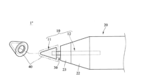
あるいは、図5を参照して、本開示の一実施形態に係るペン芯10を含むスタイラスペン1’が提供され、図示のように、ペン芯10の先端部11とペンホルダー20との間に形成されたスロット110があってもよく、スロット110はリング状であってもよく、スロット110に解放可能に係合する絶縁カバー40が存在してもよい。絶縁カバー40は、プラスチック、ゴム、シリコーン、またはそれらの組合せなど、任意の適切な電気絶縁材料で形成されてもよい。絶縁カバー40がスロット110と係合すると、絶縁カバー40はペン芯10の先端部11を覆い、スタイラスペン1’を静電容量式タッチスクリーンに適用できるようにする。
Alternatively, referring to FIG. 5, a stylus pen 1' including a
あるいは、図6を参照して、本開示の一実施形態に係るペン芯10を含むスタイラスペン1’’が提供され、図示のように、先端部11とペンホルダー20はその間にスロット30を形成し、絶縁カバー40はスロット30に解放可能に係合される。絶縁カバー40がスロット110に係合されると、絶縁カバー40がペン芯10の先端部11を覆い、スタイラスペン1’’を静電容量式タッチパネルに適用できるようにする。
Alternatively, referring to FIG. 6, a stylus pen 1'' including a
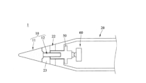
スタイラスペン1の内部は、図7に模式的に示されている。図示のように、スタイラスペン1は、ペンホルダー20にロッド固定シート50と圧力センサー60を含んでいてもよい。ロッド固定シート50は、ペンホルダー20に対するペン芯10の位置を確保するように、ペン芯10の挿入部12を受けるように構成される。ロッド固定シート50は、任意の適切な導電性材料で形成されてもよい。ペンホルダー20の挿入部12は、ロッド固定シート50に圧力センサー60を押し付けることによって、圧力センサー60を作動させることができる。
The inside of the
次に、図8を参照して、別の実施形態係るペン芯10a’が提供され、挿入部12を外部構造(例えば、前述のロッド固定シート50)による損傷または摩耗から保護するように、挿入部12に着脱可能にスリーブされたスリーブ70が存在する。
Next, referring to FIG. 8, a
次に、図9を参照して、他の実施形態に係るペン芯10dが提供され、ペン芯10dは、互いに一体的に形成される先端部11a’と挿入部12’’’を含む。具体的には、先端部11a’と挿入部12’’’は、黒鉛、鉛、または銀などの導電性を有し、紙に書くことができる材料で一体的に形成されてもよい。
Next, referring to FIG. 9, a pen core 10d according to another embodiment is provided, and the pen core 10d includes a
本開示の上記実施形態で説明したスタイラスペンおよびペン芯によれば、ペン芯の先端部は導電性で紙に書くことができるので、ペン芯によってスタイラスペンはタッチスクリーンへの指示入力だけでなく、紙に書くことや描くこともでき、ユーザはタッチスクリーンまたは紙に選択的に書くことが可能になる。 According to the stylus pen and pen core described in the above embodiment of the present disclosure, the tip of the pen core is conductive and can be used to write on paper, so the pen core allows the stylus pen to not only input instructions to the touch screen, but also to write or draw on paper, allowing the user to selectively write on the touch screen or on paper.
本開示に様々な修正および変形を加えることができることは、当業者にとって明らかであろう。本明細書および実施例は、例示的な実施形態としてのみ考慮されることが意図されており、本開示の範囲は、以下の請求項およびその等価物によって示される。
It will be apparent to those skilled in the art that various modifications and variations can be made to the present disclosure. It is intended that the specification and examples be considered as exemplary embodiments only, and the scope of the present disclosure is indicated by the following claims and their equivalents.
Claims (7)
前記ロッド本体の一端に配置された先端部と、前記先端部に接続され、前記ロッド本体に着脱可能に挿入される挿入部とを備え、前記先端部が前記電極構造体から離間しているペン芯と、を備え、
前記挿入部は導電性を有し、前記先端部は導電性を有し、かつ紙に書き込み可能な材料で形成され、
前記挿入部が、前記先端部に部分的に挿入され、
前記挿入部は、ロッド部と、当接ブロック部と、埋め込み部とを含み、前記当接ブロック部は、前記ロッド部と前記埋め込み部との間に接続され、前記当接ブロック部は、台形状の断面を有し、前記埋め込み部は、前記先端部に挿入され、前記当接ブロック部から離れる方向にテーパー状である、スタイラスペン。 A pen holder including a rod body and an electrode structure disposed on the rod body;
a pen core including a tip portion disposed at one end of the rod body, and an insertion portion connected to the tip portion and removably inserted into the rod body, the tip portion being spaced apart from the electrode structure;
the insertion portion is conductive, the tip portion is conductive, and is formed of a material that can be written on paper;
the insertion portion is partially inserted into the tip portion,
A stylus pen, wherein the insertion portion includes a rod portion, an abutment block portion, and an embedded portion, the abutment block portion is connected between the rod portion and the embedded portion, the abutment block portion has a trapezoidal cross-section, and the embedded portion is inserted into the tip portion and is tapered in a direction away from the abutment block portion .
前記先端部に挿入される挿入部と、を備え、
前記挿入部は導電性を有し、前記先端部は導電性を有し、かつ紙に書き込み可能な材料で形成され、
前記挿入部が、前記先端部に部分的に挿入され、
前記挿入部は、ロッド部と、当接ブロック部と、埋め込み部とを含み、前記当接ブロック部は、前記ロッド部と前記埋め込み部との間に接続され、前記当接ブロック部は、台形状の断面を有し、前記埋め込み部は、前記先端部に挿入され、前記当接ブロック部から離れる方向にテーパー状である、ペン芯。 A tip portion,
An insertion portion that is inserted into the tip portion,
the insertion portion is conductive, the tip portion is conductive, and is formed of a material that can be written on paper ;
the insertion portion is partially inserted into the tip portion,
The pen core, wherein the insertion portion includes a rod portion, an abutment block portion, and an embedded portion, the abutment block portion is connected between the rod portion and the embedded portion, the abutment block portion has a trapezoidal cross section, and the embedded portion is inserted into the tip portion and is tapered in a direction away from the abutment block portion .
Applications Claiming Priority (2)
| Application Number | Priority Date | Filing Date | Title |
|---|---|---|---|
| US202263347936P | 2022-06-01 | 2022-06-01 | |
| US63/347,936 | 2022-06-01 |
Publications (2)
| Publication Number | Publication Date |
|---|---|
| JP2023177249A JP2023177249A (en) | 2023-12-13 |
| JP7547546B2 true JP7547546B2 (en) | 2024-09-09 |
Family
ID=88790704
Family Applications (1)
| Application Number | Title | Priority Date | Filing Date |
|---|---|---|---|
| JP2023066458A Active JP7547546B2 (en) | 2022-06-01 | 2023-04-14 | Stylus pen and its pen tip |
Country Status (5)
| Country | Link |
|---|---|
| US (1) | US11966522B2 (en) |
| JP (1) | JP7547546B2 (en) |
| CN (1) | CN117148983A (en) |
| DE (1) | DE102022134938A1 (en) |
| TW (1) | TWI857376B (en) |
Citations (3)
| Publication number | Priority date | Publication date | Assignee | Title |
|---|---|---|---|---|
| JP3214048U (en) | 2017-10-04 | 2017-12-14 | 煥徳科技股▲ふん▼有限公司 | Capacitive stylus pen with magnetic suction assembly |
| US20190384996A1 (en) | 2018-06-19 | 2019-12-19 | Samsung Electronics Co., Ltd. | Stylus pen, electronic device, and digital copy generating method |
| CN113178900A (en) | 2021-03-15 | 2021-07-27 | 荣耀终端有限公司 | Wireless charging system, chip and wireless charging circuit |
Family Cites Families (15)
| Publication number | Priority date | Publication date | Assignee | Title |
|---|---|---|---|---|
| TW201126388A (en) * | 2010-01-29 | 2011-08-01 | Fih Hong Kong Ltd | Stylus |
| TW201241676A (en) * | 2011-04-13 | 2012-10-16 | Elan Microelectronics Corp | Capacitive touch pen |
| TWM431375U (en) * | 2011-08-24 | 2012-06-11 | Dexin Corp | Touch pen with wireless voice capability |
| JP5667708B2 (en) * | 2013-06-20 | 2015-02-12 | 株式会社ワコム | Position indicator and core of position indicator |
| KR102248709B1 (en) * | 2014-07-08 | 2021-05-07 | 가부시키가이샤 와코무 | Position indicator |
| KR102306323B1 (en) * | 2014-07-10 | 2021-09-30 | 가부시키가이샤 와코무 | Position indicator, and production method therefor |
| CN108292174B (en) * | 2015-12-21 | 2021-08-31 | 株式会社和冠 | electronic pen |
| US10549571B1 (en) * | 2017-05-10 | 2020-02-04 | Jeffrey Talley Abel | Tactical pen |
| US20190155408A1 (en) * | 2017-11-20 | 2019-05-23 | Adonit Co., Ltd | Electrical stylus tip and stylus using the same |
| TWI687846B (en) * | 2018-08-03 | 2020-03-11 | 矽統科技股份有限公司 | Two-way active stylus and sensing system |
| CN120653129A (en) * | 2018-11-09 | 2025-09-16 | 株式会社和冠 | Capacitance type electronic pen |
| JP7425043B2 (en) * | 2019-03-22 | 2024-01-30 | 株式会社ワコム | electronic pen |
| TW202202984A (en) * | 2020-07-13 | 2022-01-16 | 瑞納瑟科技股份有限公司 | Stylus |
| CN214011949U (en) * | 2020-08-25 | 2021-08-20 | 广州视源电子科技股份有限公司 | smart pen |
| CN213958026U (en) * | 2021-01-29 | 2021-08-13 | 广州文声电子科技有限公司 | Touch control pen |
-
2022
- 2022-10-26 TW TW111140550A patent/TWI857376B/en active
- 2022-11-21 CN CN202211472834.3A patent/CN117148983A/en active Pending
- 2022-12-27 US US18/089,296 patent/US11966522B2/en active Active
- 2022-12-28 DE DE102022134938.1A patent/DE102022134938A1/en active Pending
-
2023
- 2023-04-14 JP JP2023066458A patent/JP7547546B2/en active Active
Patent Citations (3)
| Publication number | Priority date | Publication date | Assignee | Title |
|---|---|---|---|---|
| JP3214048U (en) | 2017-10-04 | 2017-12-14 | 煥徳科技股▲ふん▼有限公司 | Capacitive stylus pen with magnetic suction assembly |
| US20190384996A1 (en) | 2018-06-19 | 2019-12-19 | Samsung Electronics Co., Ltd. | Stylus pen, electronic device, and digital copy generating method |
| CN113178900A (en) | 2021-03-15 | 2021-07-27 | 荣耀终端有限公司 | Wireless charging system, chip and wireless charging circuit |
Also Published As
| Publication number | Publication date |
|---|---|
| TWI857376B (en) | 2024-10-01 |
| DE102022134938A1 (en) | 2023-12-07 |
| TW202349164A (en) | 2023-12-16 |
| JP2023177249A (en) | 2023-12-13 |
| US20230393671A1 (en) | 2023-12-07 |
| CN117148983A (en) | 2023-12-01 |
| US11966522B2 (en) | 2024-04-23 |
Similar Documents
| Publication | Publication Date | Title |
|---|---|---|
| JP5369122B2 (en) | Stylus for capacitive touch panel | |
| CN106406576B (en) | Method and kit for simultaneously forming entity handwriting and electronic handwriting and touch pen | |
| US9671877B2 (en) | Stylus tool with deformable tip | |
| US20090211821A1 (en) | Capacitive stylus pen | |
| US20150212600A1 (en) | Stylus tool with deformable tip | |
| WO2020054163A1 (en) | Electronic pen and core body for electronic pens | |
| JP2012053681A (en) | Stylus pen for touch panel | |
| TW201241676A (en) | Capacitive touch pen | |
| CN109683730A (en) | Stylus and touch-control system with it | |
| TW202008104A (en) | Side-press type pointer | |
| JP2013137749A (en) | Input stylus pen | |
| JP7547546B2 (en) | Stylus pen and its pen tip | |
| JP5832237B2 (en) | Information input pen | |
| KR101260904B1 (en) | Writing apparatus having the function of stylus pen for touch screen | |
| CN109426370B (en) | Touch pen and display device using same | |
| JP4815145B2 (en) | Pen-type input device, pen, and holding member for holding a pen core | |
| KR101180973B1 (en) | The writing apparatus with the touch pen function | |
| CN111813247A (en) | Mouse pen and electronic equipment | |
| JP3189356U (en) | Electrostatic input pen | |
| JP2011242903A (en) | Capacitive pen | |
| JP6173878B2 (en) | Pencil and pencil cap | |
| JP2014063317A (en) | Stylus pen and touch panel system | |
| JP2023072855A (en) | touch pen | |
| CN215181911U (en) | Handwriting pen for electronic equipment | |
| CN215006584U (en) | Touch control pen |
Legal Events
| Date | Code | Title | Description |
|---|---|---|---|
| A621 | Written request for application examination |
Free format text: JAPANESE INTERMEDIATE CODE: A621 Effective date: 20230414 |
|
| A131 | Notification of reasons for refusal |
Free format text: JAPANESE INTERMEDIATE CODE: A131 Effective date: 20240305 |
|
| A521 | Request for written amendment filed |
Free format text: JAPANESE INTERMEDIATE CODE: A523 Effective date: 20240502 |
|
| TRDD | Decision of grant or rejection written | ||
| A01 | Written decision to grant a patent or to grant a registration (utility model) |
Free format text: JAPANESE INTERMEDIATE CODE: A01 Effective date: 20240806 |
|
| A61 | First payment of annual fees (during grant procedure) |
Free format text: JAPANESE INTERMEDIATE CODE: A61 Effective date: 20240828 |
|
| R150 | Certificate of patent or registration of utility model |
Ref document number: 7547546 Country of ref document: JP Free format text: JAPANESE INTERMEDIATE CODE: R150 |