JP7547520B2 - Light-shielding film, light-shielding member, and optical component - Google Patents
Light-shielding film, light-shielding member, and optical component Download PDFInfo
- Publication number
- JP7547520B2 JP7547520B2 JP2023001951A JP2023001951A JP7547520B2 JP 7547520 B2 JP7547520 B2 JP 7547520B2 JP 2023001951 A JP2023001951 A JP 2023001951A JP 2023001951 A JP2023001951 A JP 2023001951A JP 7547520 B2 JP7547520 B2 JP 7547520B2
- Authority
- JP
- Japan
- Prior art keywords
- light
- shielding
- layer
- substrate
- shielding film
- Prior art date
- Legal status (The legal status is an assumption and is not a legal conclusion. Google has not performed a legal analysis and makes no representation as to the accuracy of the status listed.)
- Active
Links
Classifications
-
- G—PHYSICS
- G02—OPTICS
- G02B—OPTICAL ELEMENTS, SYSTEMS OR APPARATUS
- G02B5/00—Optical elements other than lenses
- G02B5/02—Diffusing elements; Afocal elements
- G02B5/0205—Diffusing elements; Afocal elements characterised by the diffusing properties
- G02B5/021—Diffusing elements; Afocal elements characterised by the diffusing properties the diffusion taking place at the element's surface, e.g. by means of surface roughening or microprismatic structures
- G02B5/0226—Diffusing elements; Afocal elements characterised by the diffusing properties the diffusion taking place at the element's surface, e.g. by means of surface roughening or microprismatic structures having particles on the surface
-
- G—PHYSICS
- G02—OPTICS
- G02B—OPTICAL ELEMENTS, SYSTEMS OR APPARATUS
- G02B5/00—Optical elements other than lenses
- G02B5/20—Filters
- G02B5/22—Absorbing filters
- G02B5/223—Absorbing filters containing organic substances, e.g. dyes, inks or pigments
-
- C—CHEMISTRY; METALLURGY
- C08—ORGANIC MACROMOLECULAR COMPOUNDS; THEIR PREPARATION OR CHEMICAL WORKING-UP; COMPOSITIONS BASED THEREON
- C08J—WORKING-UP; GENERAL PROCESSES OF COMPOUNDING; AFTER-TREATMENT NOT COVERED BY SUBCLASSES C08B, C08C, C08F, C08G or C08H
- C08J5/00—Manufacture of articles or shaped materials containing macromolecular substances
-
- C—CHEMISTRY; METALLURGY
- C08—ORGANIC MACROMOLECULAR COMPOUNDS; THEIR PREPARATION OR CHEMICAL WORKING-UP; COMPOSITIONS BASED THEREON
- C08J—WORKING-UP; GENERAL PROCESSES OF COMPOUNDING; AFTER-TREATMENT NOT COVERED BY SUBCLASSES C08B, C08C, C08F, C08G or C08H
- C08J7/00—Chemical treatment or coating of shaped articles made of macromolecular substances
- C08J7/04—Coating
- C08J7/0427—Coating with only one layer of a composition containing a polymer binder
-
- G—PHYSICS
- G02—OPTICS
- G02B—OPTICAL ELEMENTS, SYSTEMS OR APPARATUS
- G02B1/00—Optical elements characterised by the material of which they are made; Optical coatings for optical elements
- G02B1/10—Optical coatings produced by application to, or surface treatment of, optical elements
- G02B1/11—Anti-reflection coatings
-
- G—PHYSICS
- G02—OPTICS
- G02B—OPTICAL ELEMENTS, SYSTEMS OR APPARATUS
- G02B5/00—Optical elements other than lenses
- G02B5/20—Filters
- G02B5/28—Interference filters
Landscapes
- Physics & Mathematics (AREA)
- Chemical & Material Sciences (AREA)
- General Physics & Mathematics (AREA)
- Optics & Photonics (AREA)
- Organic Chemistry (AREA)
- Chemical Kinetics & Catalysis (AREA)
- Medicinal Chemistry (AREA)
- Polymers & Plastics (AREA)
- Health & Medical Sciences (AREA)
- Engineering & Computer Science (AREA)
- Manufacturing & Machinery (AREA)
- Materials Engineering (AREA)
- Optical Elements Other Than Lenses (AREA)
- Lens Barrels (AREA)
- Laminated Bodies (AREA)
- Vessels, Lead-In Wires, Accessory Apparatuses For Cathode-Ray Tubes (AREA)
- Electrochromic Elements, Electrophoresis, Or Variable Reflection Or Absorption Elements (AREA)
Description
本開示は、遮光フィルム及び遮光部材に関する。 This disclosure relates to light-shielding films and light-shielding members.
スマートフォンやデジタルビデオカメラ等が備える光学部品のシャッター、絞り部材、又は複数のレンズ間に配置されるギャップ調整部材として、例えば特許文献1に開示されるような遮光部材が用いられる。遮光部材は、例えば、シート状の基材と、基材の表面に重ねて配置された遮光層とを備える遮光フィルムを用いて製造される。遮光層の表面には、微細な凹凸が形成される。遮光層は、光学部品に外部から入射した入射光を散乱させて写り込みを防止すると共に、入射光を遮光する。 A light-shielding member such as that disclosed in Patent Document 1 is used as a shutter, an aperture member, or a gap adjustment member arranged between multiple lenses in optical components equipped in smartphones, digital video cameras, etc. The light-shielding member is manufactured, for example, using a light-shielding film that includes a sheet-like substrate and a light-shielding layer arranged over the surface of the substrate. Fine irregularities are formed on the surface of the light-shielding layer. The light-shielding layer scatters incident light that is incident on the optical component from the outside to prevent reflections and also blocks the incident light.
光学部品の小型化に伴い、遮光部材には、例えば、厚みが薄くても優れた遮光性を有することが求められる。また遮光フィルムは、例えば、複数の材料を準備した後、各材料を重ね、表面を硬化して形成される。このため、遮光性に優れる遮光部材を効率よく製造することが望まれている。 As optical components become smaller, light-shielding members are required to have excellent light-shielding properties even when they are thin. Light-shielding films are formed, for example, by preparing multiple materials, layering the materials, and curing the surfaces. For this reason, it is desirable to efficiently manufacture light-shielding members with excellent light-shielding properties.
そこで本開示は、遮光性に優れる遮光部材を効率よく製造可能にすることを目的としている。 Therefore, the purpose of this disclosure is to enable the efficient production of light-shielding members with excellent light-shielding properties.
上記課題を解決するために、本開示の一態様に係る遮光フィルムは、遮光性を有するシート状の基材と、前記基材に重ねて配置され、前記基材とは反対側の表面に凹凸が形成され、前記基材よりも透明な光沢防止層と、を備える。前記光沢防止層は、バインダ樹脂と、前記バインダ樹脂中に分散されたフィラー粒子と、前記バインダ樹脂中に分散された着色成分と、を含む。この遮光フィルムは、JIS Z 8518に規定される明度である黒味(L*)が、15以下の範囲の値に設定されている。 In order to solve the above problems, a light-shielding film according to one aspect of the present disclosure includes a sheet-like substrate having light-shielding properties, and an anti-gloss layer disposed on the substrate, with unevenness formed on the surface opposite to the substrate, and more transparent than the substrate. The anti-gloss layer includes a binder resin, filler particles dispersed in the binder resin, and a coloring component dispersed in the binder resin. The light-shielding film has a blackness (L * ) as defined in JIS Z 8518 set to a value in the range of 15 or less.
上記構成によれば、外部から入射した入射光を光沢防止層の表面の凹凸で散乱させるアンチグレア性を遮光フィルムに付与できる。また、光沢防止層中に入射した入射光が、フィラー粒子の表面で反射して光沢防止層の表面から出射するのを、着色成分により抑制できる。また遮光フィルムは、JIS Z 8518に規定される明度である黒味(L*)が、15以下の範囲の値に設定される。また光沢防止層は、基材よりも透明に構成される。このため、光沢防止層を通じて基材の遮光性を外部に発揮できる。その結果、明度が低く且つ優れた遮光性を有する遮光フィルムを実現できる。 According to the above-mentioned configuration, the light-shielding film can be given anti-glare properties that scatter the light incident from the outside by the unevenness of the surface of the anti-gloss layer. In addition, the coloring component can suppress the light incident into the anti-gloss layer from being reflected by the surface of the filler particles and being emitted from the surface of the anti-gloss layer. In addition, the light-shielding film has a blackness (L * ) that is the brightness defined in JIS Z 8518 set to a value in the range of 15 or less. In addition, the anti-gloss layer is configured to be more transparent than the substrate. Therefore, the light-shielding properties of the substrate can be exhibited to the outside through the anti-gloss layer. As a result, a light-shielding film having low brightness and excellent light-shielding properties can be realized.
また光沢防止層は、例えば、バインダ樹脂前駆体、フィラー粒子、及び着色成分を含む塗工液を基材の表面に塗工して硬化することで形成できる。また、光沢防止層中の着色成分の含有量を上記範囲に設定することで、着色成分によって光沢防止層の遮光性が過度になるのを抑制できる。よって、バインダ樹脂前駆体に例えば紫外線硬化性樹脂等の光硬化性樹脂を用いても、外部からバインダ樹脂前駆体に光照射することで、バインダ樹脂を硬化できる。これにより、光沢防止層を効率よく形成できる。よって、遮光フィルムを用いて遮光部材を効率よく製造できる。 The anti-gloss layer can be formed, for example, by applying a coating liquid containing a binder resin precursor, filler particles, and a coloring component to the surface of the substrate and curing the coating liquid. By setting the content of the coloring component in the anti-gloss layer within the above range, it is possible to prevent the anti-gloss layer from having excessive light-shielding properties due to the coloring component. Therefore, even if a photocurable resin such as an ultraviolet-curable resin is used as the binder resin precursor, the binder resin can be cured by irradiating the binder resin precursor with light from the outside. This allows the anti-gloss layer to be formed efficiently. Therefore, light-shielding members can be efficiently manufactured using the light-shielding film.
前記光沢防止層の前記フィラー粒子の含有量が、10wt%以上25wt%以下の範囲の値であってもよい。これにより、光沢防止層の表面に凹凸を形成し易くできる。また前記光沢防止層の前記着色成分の含有量が、0wt%よりも多く5wt%以下の範囲の値であってもよい。これにより、フィラー粒子の表面で反射した反射光を着色成分により抑制し易くできる。 The content of the filler particles in the anti-gloss layer may be a value in the range of 10 wt% to 25 wt%. This makes it easier to form irregularities on the surface of the anti-gloss layer. The content of the coloring component in the anti-gloss layer may be a value in the range of more than 0 wt% to 5 wt%. This makes it easier to suppress reflected light reflected on the surface of the filler particles by the coloring component.
前記着色成分は、前記フィラー粒子よりも粒径が小さい顔料微粒子を含んでいてもよい。これにより、光沢防止層中においてフィラー粒子の周辺に複数の顔料微粒子を配置することで、光沢防止層中に入射した入射光がフィラー粒子の表面で反射して光沢防止層の表面から出射されるのを顔料微粒子により一層抑制し易くできる。 The coloring component may contain pigment fine particles having a particle size smaller than that of the filler particles. In this way, by disposing a plurality of pigment fine particles around the filler particles in the anti-gloss layer, it becomes easier for the pigment fine particles to suppress incident light that has entered the anti-gloss layer from being reflected by the surfaces of the filler particles and being emitted from the surface of the anti-gloss layer.
波長380nm以上780nm以下の範囲の値におけるOD値が、5以上の範囲の値であってもよい。これにより、より一層良好な遮光フィルムの遮光性が得られる。 The OD value at wavelengths in the range of 380 nm to 780 nm may be a value in the range of 5 or more. This provides even better light-blocking properties for the light-blocking film.
総厚みが、40μm以下の範囲の値であってもよい。このように総厚みを薄くした遮光フィルムを用いれば、例えば光学部品の大型化を抑制しながら、光学部品内に優れた遮光性を有する遮光部材をコンパクトに配置できる。 The total thickness may be in the range of 40 μm or less. By using a light-shielding film with a thin total thickness in this way, it is possible to compactly arrange a light-shielding member with excellent light-shielding properties within an optical component, for example, while preventing the optical component from becoming large.
前記基材は、フィルム部材と、前記フィルム部材よりも高い遮光性を有し、前記フィルム部材に重ねて配置される遮光層とを含み、前記フィルム部材と前記遮光層とのうち、前記遮光層が前記光沢防止層側となるように配置されてもよい。また前記基材は、遮光性を有するフィルム部材を含んでいてもよい。これにより、遮光フィルムの設計自由度を向上できる。 The substrate may include a film member and a light-shielding layer having a higher light-shielding property than the film member and arranged to overlap the film member, and the film member and the light-shielding layer may be arranged so that the light-shielding layer is on the gloss-preventing layer side. The substrate may also include a film member having light-shielding properties. This can improve the design freedom of the light-shielding film.
本開示の一態様に係る遮光部材は、遮光性を有するシート状の基材と、前記基材に重ねて配置され、前記基材とは反対側の表面に凹凸が形成され、前記基材よりも透明な光沢防止層と、を備え、前記光沢防止層は、バインダ樹脂と、前記バインダ樹脂中に分散されたフィラー粒子と、前記バインダ樹脂中に分散された着色成分と、を含み、顕微分光測定により測定した明度である黒味(L*)が、3.1以下の範囲の値に設定されている。 A light-shielding member according to one embodiment of the present disclosure comprises a sheet-like substrate having light-shielding properties, and an anti-gloss layer arranged on top of the substrate, with irregularities formed on the surface opposite the substrate and more transparent than the substrate, wherein the anti-gloss layer contains a binder resin, filler particles dispersed in the binder resin, and a coloring component dispersed in the binder resin, and the blackness (L * ), which is the lightness measured by microspectroscopic measurement, is set to a value in the range of 3.1 or less.
上記構成によれば、外部から入射した入射光を光沢防止層の表面の凹凸で散乱させるアンチグレア性を遮光部材に付与できる。また、光沢防止層中に入射した入射光が、フィラー粒子の表面で反射して光沢防止層の表面から出射するのを、着色成分により抑制できる。これにより、光沢防止層の表面の明度を良好に低減できる。顕微分光測定により測定した明度である黒味(L*)が、3.1以下の範囲の値に設定される。また光沢防止層は、基材よりも透明に構成される。このため、光沢防止層を通じて基材の遮光性を外部に発揮できる。その結果、明度が低く且つ優れた遮光性を有する遮光部材を実現できる。 According to the above configuration, the light-shielding member can be given anti-glare properties that scatter the incident light from the outside by the unevenness of the surface of the anti-gloss layer. In addition, the coloring component can suppress the incident light that enters the anti-gloss layer from being reflected by the surface of the filler particles and exiting from the surface of the anti-gloss layer. This allows the brightness of the surface of the anti-gloss layer to be reduced satisfactorily. The blackness (L * ), which is the brightness measured by microspectroscopic measurement, is set to a value in the range of 3.1 or less. In addition, the anti-gloss layer is configured to be more transparent than the substrate. Therefore, the light-shielding properties of the substrate can be exhibited to the outside through the anti-gloss layer. As a result, a light-shielding member having low brightness and excellent light-shielding properties can be realized.
本開示の各態様によれば、遮光性に優れる遮光フィルムを効率よく製造できる。 According to each aspect of the present disclosure, a light-shielding film with excellent light-shielding properties can be efficiently manufactured.
以下、各実施形態等について、図面を参照して説明する。本開示におけるwt%とは質量パーセントである。質量パーセントは、重量パーセント、略してwt%、又は重量-重量パーセントとして表すこともできる。質量パーセントは質量[g]/質量[g]の濃度の百分率表記であり、質量濃度(kg/m3)とは異なる。
(第1実施形態)
[遮光フィルム]
図1は、第1実施形態に係る遮光フィルム1の断面図である。図2は、図1の遮光フィルム1の部分拡大図である。図1及び2に示される遮光フィルム1は、一例として、光学部品の遮光部材の製造に用いられる。遮光フィルム1は、遮光性を有するシート状の基材2と、基材2に重ねて配置された少なくとも1つ(ここでは一対)の光沢防止層3とを備える。基材2は、一対の光沢防止層3よりも高い遮光性を有する。言い換えると、光沢防止層3は、基材2よりも透明である。即ち光沢防止層3は、全光線透過率が基材2よりも高い。
Hereinafter, each embodiment will be described with reference to the drawings. In this disclosure, wt% means mass percent. Mass percent can also be expressed as weight percent, abbreviated as wt%, or weight-weight percent. Mass percent is a percentage expression of concentration of mass [g]/mass [g], and is different from mass concentration (kg/m 3 ).
First Embodiment
[Light-shielding film]
FIG 1 is a cross-sectional view of a light-shielding film 1 according to a first embodiment. FIG 2 is a partially enlarged view of the light-shielding film 1 of FIG 1. The light-shielding film 1 shown in FIGS. 1 and 2 is used, for example, in the manufacture of a light-shielding member of an optical component. The light-shielding film 1 includes a sheet-like substrate 2 having light-shielding properties, and at least one (here, a pair) of anti-gloss layers 3 arranged on the substrate 2. The substrate 2 has a higher light-shielding property than the pair of anti-gloss layers 3. In other words, the anti-gloss layer 3 is more transparent than the substrate 2. That is, the total light transmittance of the anti-gloss layer 3 is higher than that of the substrate 2.
本書で言う全光線透過率とは、JIS K 7375:2008に準拠する方法で測定された透過率を指す。遮光フィルム1では、光沢防止層3を通じて、基材2の遮光性が発揮される。遮光フィルム1の総厚みは、一例として40μm以下の範囲の値である。別の例では、遮光フィルム1の総厚みは、50μm以下の範囲の値である。また別の例では、遮光フィルム1の総厚みは、25μm以下の範囲の値である。 The total light transmittance referred to in this document refers to the transmittance measured by a method conforming to JIS K 7375:2008. In the light-shielding film 1, the light-shielding properties of the substrate 2 are exhibited through the anti-gloss layer 3. As an example, the total thickness of the light-shielding film 1 is a value in the range of 40 μm or less. In another example, the total thickness of the light-shielding film 1 is a value in the range of 50 μm or less. In yet another example, the total thickness of the light-shielding film 1 is a value in the range of 25 μm or less.
基材2は、光沢防止層3を支持すると共に、遮光フィルム1に遮光性を付与する。本実施形態の基材2は、遮光性を有するフィルム部材を含む。一例として、基材2は、着色成分(ここでは黒色成分)と、樹脂成分とを含む樹脂フィルムである。黒色成分としては、カーボンブラックを例示できるが、これに限定されない。樹脂成分としては、ポリエチレンテレフタレート(PET)、ポリイミド(PI)、ポリ塩化ビニル(PVC)、ポリプロピレン(PP)、ポリスチレン(PS)、ポリカーボネート(PC)、エチレン-メタクリル酸共重合体(EMAA)のうちの1種以上を例示できるが、これに限定されない。基材2の厚みは、遮光フィルム1の総厚みを考慮した上で適宜設定可能である。一例として、基材2の厚みは、4.5μm以上25μm未満の範囲の値である。また別の例では、基材2の厚みは、50μm以下の範囲の値である。基材2の波長380nm以上780nm以下の範囲の値におけるOD(光学濃度)値は、一例として4以上の範囲の値である。 The substrate 2 supports the anti-gloss layer 3 and provides the light-shielding film 1 with light-shielding properties. The substrate 2 of this embodiment includes a film member having light-shielding properties. As an example, the substrate 2 is a resin film containing a coloring component (here, a black component) and a resin component. An example of the black component is carbon black, but is not limited to this. Examples of the resin component include, but are not limited to, one or more of polyethylene terephthalate (PET), polyimide (PI), polyvinyl chloride (PVC), polypropylene (PP), polystyrene (PS), polycarbonate (PC), and ethylene-methacrylic acid copolymer (EMAA). The thickness of the substrate 2 can be appropriately set in consideration of the total thickness of the light-shielding film 1. As an example, the thickness of the substrate 2 is a value in the range of 4.5 μm or more and less than 25 μm. In another example, the thickness of the substrate 2 is a value in the range of 50 μm or less. The OD (optical density) value of the substrate 2 at wavelengths in the range of 380 nm to 780 nm is, for example, a value in the range of 4 or more.
光沢防止層3は、基材2に重ねて配置される。光沢防止層3は、基材2とは反対側の表面に凹凸が形成されている。この凹凸は、光沢防止層3に外部から入射する入射光を散乱する。遮光フィルム1が光沢防止層3を備えることで、遮光フィルム1はアンチグレア性を有する。 The anti-gloss layer 3 is disposed over the substrate 2. The anti-gloss layer 3 has irregularities formed on the surface opposite the substrate 2. These irregularities scatter incident light that is incident on the anti-gloss layer 3 from the outside. The light-shielding film 1 has anti-glare properties because it is provided with the anti-gloss layer 3.
光沢防止層3は、全光線透過率が70%以上100%未満の範囲の値であるバインダ樹脂30と、バインダ樹脂30中に分散されたフィラー粒子31と、バインダ樹脂30中に分散された着色成分32とを含む。光沢防止層3の表面の凹凸は、複数のフィラー粒子31がバインダ樹脂30中に分散されて配置されると共に、フィラー粒子31が光沢防止層3の基材2とは反対側に突出してバインダ樹脂30の表面を隆起させることで形成されている。フィラー粒子31は、一例として無機粒子である。この場合、フィラー粒子31としてはシリカ粒子を例示できる。フィラー粒子31は無機材料を含む構成に限定されず、有機材料を含む構成であってもよい。 The anti-gloss layer 3 includes a binder resin 30 having a total light transmittance in the range of 70% or more and less than 100%, a filler particle 31 dispersed in the binder resin 30, and a coloring component 32 dispersed in the binder resin 30. The unevenness on the surface of the anti-gloss layer 3 is formed by dispersing and arranging a plurality of filler particles 31 in the binder resin 30, and by the filler particles 31 protruding to the opposite side of the anti-gloss layer 3 from the substrate 2 to raise the surface of the binder resin 30. The filler particles 31 are, for example, inorganic particles. In this case, an example of the filler particles 31 is silica particles. The filler particles 31 are not limited to a composition containing an inorganic material, and may be a composition containing an organic material.
フィラー粒子31の平均粒径は、適宜設定可能である。本実施形態のフィラー粒子31の平均粒径は、2.0μm以上5.0μm以下の範囲の値である。フィラー粒子31の平均粒径は、2.5μm以上4.5μm以下の範囲の値であることがより望ましい。またフィラー粒子31の平均粒径は、2.7μm以上3.5μm以下の範囲の値であることが、一層望ましい。 The average particle size of the filler particles 31 can be set as appropriate. In this embodiment, the average particle size of the filler particles 31 is a value in the range of 2.0 μm or more and 5.0 μm or less. It is more preferable that the average particle size of the filler particles 31 is a value in the range of 2.5 μm or more and 4.5 μm or less. It is even more preferable that the average particle size of the filler particles 31 is a value in the range of 2.7 μm or more and 3.5 μm or less.
本実施形態の着色成分32は、フィラー粒子31よりも高い光吸収性を有する。図2に示すように、着色成分32は、一例として顔料微粒子を含む。この顔料微粒子は、フィラー粒子31よりも粒径が小さい。光沢防止層3中では、複数の顔料微粒子がフィラー粒子31の周囲に分散して配置されている。これにより光沢防止層3では、光沢防止層3中に外部から光が入射した場合でも、フィラー粒子31の表面で反射した反射光が、再び光沢防止層3の表面から外部に出射されるのが顔料微粒子により抑制される。複数の顔料微粒子は、各々が分離した一次粒子状に配置されていてもよいし、ある程度の数で凝集した二次粒子状に配置されていてもよい。 The coloring component 32 of this embodiment has higher light absorption than the filler particles 31. As shown in FIG. 2, the coloring component 32 includes pigment fine particles as an example. The pigment fine particles have a smaller particle size than the filler particles 31. In the gloss-preventing layer 3, a plurality of pigment fine particles are dispersed and arranged around the filler particles 31. As a result, even if light is incident on the gloss-preventing layer 3 from the outside, the pigment fine particles suppress the reflected light reflected on the surface of the filler particles 31 from being emitted again to the outside from the surface of the gloss-preventing layer 3. The plurality of pigment fine particles may be arranged in the form of separate primary particles, or may be arranged in the form of secondary particles aggregated in a certain number.
着色成分32としては、例えば顔料や染料を例示できるが、これに限定されない。また着色成分32としては、例えば、カーボンブラック、ランプブラック、バインブラック、ピーチブラック、骨炭、カーボンナノチューブ、酸化銀、酸化亜鉛、マグネタイト型四酸化三鉄、銅とクロムの複合酸化物、銅、クロム、亜鉛の複合酸化物、黒色ガラス等の少なくともいずれかを例示できる。本実施形態の着色成分32は、顔料微粒子としてカーボンブラック(炭素微粒子)を含む。 Examples of the coloring component 32 include, but are not limited to, pigments and dyes. Examples of the coloring component 32 include at least one of carbon black, lamp black, vine black, peach black, bone charcoal, carbon nanotubes, silver oxide, zinc oxide, magnetite-type triiron tetroxide, composite oxides of copper and chromium, composite oxides of copper, chromium, and zinc, and black glass. The coloring component 32 of this embodiment contains carbon black (carbon fine particles) as pigment fine particles.
光沢防止層3のフィラー粒子31の含有量は、10wt%以上25wt%以下の範囲の値である。光沢防止層3のフィラー粒子31の含有量の下限値を10wt%とすることで、光沢防止層3の表面の光沢を抑制して光沢防止層3に黒味を付与し易くできる。光沢防止層3のフィラー粒子31の含有量の上限値を25wt%とすることで、フィラー粒子31により光沢防止層3の明度(L*)が上昇するのを抑制できる。 The content of the filler particles 31 in the anti-gloss layer 3 is a value in the range of 10 wt % or more and 25 wt % or less. By setting the lower limit of the content of the filler particles 31 in the anti-gloss layer 3 to 10 wt %, it is possible to suppress the gloss of the surface of the anti-gloss layer 3 and to easily impart a black hue to the anti-gloss layer 3. By setting the upper limit of the content of the filler particles 31 in the anti-gloss layer 3 to 25 wt %, it is possible to suppress an increase in the lightness (L * ) of the anti-gloss layer 3 due to the filler particles 31.
光沢防止層3の着色成分32の含有量は、0wt%よりも多く5wt%以下の範囲の値である。光沢防止層3の着色成分32の含有量の下限値は、1wt%又は2wt%のいずれかでもよい。光沢防止層3の着色成分32の含有量の下限値を1wt%とすることで、光沢防止層3に適度な黒味を付与し易くできる。また光沢防止層3の着色成分32の含有量の上限値を5wt%とすることで、光沢防止層3の表面粗さ(Ra)を適切に保持し、着色成分32により光沢防止層3の黒味が低下するのを防止し易くできる。 The content of the coloring component 32 in the anti-gloss layer 3 is a value in the range of more than 0 wt% to 5 wt%. The lower limit of the content of the coloring component 32 in the anti-gloss layer 3 may be either 1 wt% or 2 wt%. By setting the lower limit of the content of the coloring component 32 in the anti-gloss layer 3 to 1 wt%, it is easy to impart an appropriate blackness to the anti-gloss layer 3. In addition, by setting the upper limit of the content of the coloring component 32 in the anti-gloss layer 3 to 5 wt%, it is easy to maintain the surface roughness (Ra) of the anti-gloss layer 3 appropriately and to prevent the blackness of the anti-gloss layer 3 from being reduced by the coloring component 32.
本実施形態のバインダ樹脂30は、光沢防止層3への用途を考慮して、一例として、全光線透過率が70%以上100%以下の範囲の値である。また一例として、バインダ樹脂30は、熱可塑性樹脂、熱硬化性樹脂、又は光硬化性樹脂の少なくともいずれかを含む。このため、バインダ樹脂30として幅広い樹脂を選択できる。これにより遮光フィルム1において、バインダ樹脂30に用いた樹脂の各機能を発揮させることができる。 In the present embodiment, the binder resin 30 has, as an example, a total light transmittance in the range of 70% or more and 100% or less, taking into consideration its use in the gloss prevention layer 3. As another example, the binder resin 30 contains at least one of a thermoplastic resin, a thermosetting resin, and a photocurable resin. Therefore, a wide range of resins can be selected as the binder resin 30. This allows the resins used in the binder resin 30 to exert their respective functions in the light-shielding film 1.
熱可塑性樹脂としては、例えば、ポリオレフィン、スチレン系樹脂、アクリル系樹脂、塩化ビニル系樹脂、ポリビニルアルコール系樹脂、ポリアセタール、ポリエステル、ポリカーボネート、ポリアミド、ポリイミド、ポリスルホン系樹脂、ポリフェニレンエーテル系樹脂、ポリフェニレンスルフィド系樹脂、フッ素樹脂、セルロース誘導体、ポリウレタン系樹脂等のうち1種以上を例示できる。このうち強度の観点では、例えば、環状ポリオレフィン、ポリアルキレンアリレート(ポリエチレンテレフタレート(PET)、ポリエチレンナフタレート(PEN)等)、ポリメタクリル酸メチル系樹脂、ビスフェノールA型ポリカーボネート、セルロースエステルが好適である。 Examples of thermoplastic resins include one or more of polyolefins, styrene-based resins, acrylic-based resins, vinyl chloride-based resins, polyvinyl alcohol-based resins, polyacetal, polyesters, polycarbonates, polyamides, polyimides, polysulfone-based resins, polyphenylene ether-based resins, polyphenylene sulfide-based resins, fluororesins, cellulose derivatives, and polyurethane-based resins. Among these, from the viewpoint of strength, for example, cyclic polyolefins, polyalkylene arylates (polyethylene terephthalate (PET), polyethylene naphthalate (PEN), etc.), polymethyl methacrylate-based resins, bisphenol A polycarbonates, and cellulose esters are preferred.
熱硬化性樹脂としては、フェノール樹脂、メラミン樹脂、尿素樹脂、ベンゾグアナミン樹脂、シリコーン樹脂、エポキシ樹脂、不飽和ポリエステル、ビニルエステル樹脂、ポリウレタン等のうち1種以上を例示できる。このうち強度の観点では、エポキシ樹脂、不飽和ポリエステル、シリコーン樹脂、ポリウレタンが好適である。 Examples of thermosetting resins include one or more of phenolic resin, melamine resin, urea resin, benzoguanamine resin, silicone resin, epoxy resin, unsaturated polyester, vinyl ester resin, polyurethane, etc. Among these, epoxy resin, unsaturated polyester, silicone resin, and polyurethane are preferable from the viewpoint of strength.
光硬化性樹脂としては、例えば、光硬化性ポリエステル、光硬化性アクリル系樹脂、光硬化性エポキシ(メタ)アクリレート、光硬化性ウレタン(メタ)アクリレート等のうち1種以上を例示できる。このうち強度の観点では、光硬化性アクリル系樹脂、光硬化性ウレタン(メタ)アクリレートが好適である。なお、ここで言う「光硬化性」は、特定波長の光により重合及び硬化する特性を指す。 Examples of photocurable resins include one or more of photocurable polyesters, photocurable acrylic resins, photocurable epoxy (meth)acrylates, and photocurable urethane (meth)acrylates. From the viewpoint of strength, photocurable acrylic resins and photocurable urethane (meth)acrylates are preferred. Note that "photocurable" here refers to the property of polymerizing and curing when exposed to light of a specific wavelength.
光沢防止層3は、波長380nm以上780nm以下の範囲の値におけるOD値が、2以下の範囲の値である。これにより、光沢防止層3に適度な黒味を付与しつつ、光沢防止層3を通じて基材2の遮光性を外部に発揮し易くできる。 The anti-gloss layer 3 has an OD value of 2 or less in the wavelength range of 380 nm to 780 nm. This gives the anti-gloss layer 3 an appropriate black hue while making it easier for the anti-gloss layer 3 to exhibit the light-blocking properties of the substrate 2 to the outside.
遮光フィルム1は、JIS Z 8518:1998に規定される明度(L*)が、15以下(一例として14以下であり、別の例では13.7以下、又は、13.2以下)の範囲の値である。また遮光フィルム1は、光沢防止層3の基材2とは反対側の表面の算術平均粗さ(Ra)が、0.2以上0.8μm以下の範囲の値である。この表面の算術平均粗さ(Ra)としては、0.4以上0.6μm以下の範囲の値がより好ましい。また遮光フィルム1は、光沢防止層3の基材2とは反対側の表面の入射角60度における光沢度が、0.5以下の範囲の値である。 The lightness (L * ) of the light-shielding film 1 as defined in JIS Z 8518:1998 is in the range of 15 or less (14 or less as an example, 13.7 or less, or 13.2 or less as another example). The arithmetic mean roughness (Ra) of the surface of the antigloss layer 3 opposite the substrate 2 of the light-shielding film 1 is in the range of 0.2 to 0.8 μm. The arithmetic mean roughness (Ra) of this surface is more preferably in the range of 0.4 to 0.6 μm. The gloss of the surface of the antigloss layer 3 opposite the substrate 2 at an incidence angle of 60 degrees of the light-shielding film 1 is in the range of 0.5 or less.
ここで、JIS Z 8518に規定される明度である黒味(L*)を測定する場合、例えば試料に光を照射し、試料からの反射光により測定する反射測定を行う。積分球方式によれば、試料表面から反射された光により積分球の内部を明るくし、検出器にてその光量を測定できる。この場合、測定値は、反射基準(標準白板)の反射率を100%とした場合の反射率(相対反射率)となる。測定方式は、測定する試料の種類や形状、測定する目的や用途に応じて使い分ける必要がある。積分球方式において、試料表面の黒味(L*)を定量化するためには、正反射光と拡散反射光とを全て測るSCI(正反射光含む)方式が適している。本書では、分光光度計((株)日立ハイテクサイエンス製「U-3900H」)を用い、SCI方式に基づき、波長380nm以上780nm以下の範囲での反射率に基づいて黒味(L*)を算出した。 Here, when measuring the blackness (L * ), which is the lightness defined in JIS Z 8518, for example, a reflection measurement is performed in which light is irradiated onto a sample and the light reflected from the sample is measured. According to the integrating sphere method, the inside of the integrating sphere is brightened by the light reflected from the sample surface, and the amount of light can be measured by a detector. In this case, the measured value is the reflectance (relative reflectance ) when the reflectance of the reflection standard (standard white board) is set to 100%. The measurement method needs to be selected according to the type and shape of the sample to be measured, the purpose and application of the measurement. In the integrating sphere method, the SCI (including specular reflection) method, which measures both specular reflection and diffuse reflection, is suitable for quantifying the blackness (L*) of the sample surface. In this document, a spectrophotometer ("U-3900H" manufactured by Hitachi High-Tech Science Co., Ltd.) was used to calculate the blackness (L * ) based on the reflectance in the wavelength range of 380 nm to 780 nm based on the SCI method.
またOD値は、光学濃度計(ビデオジェット・エックスライト(株)製「X-Rite
341C」)を用い、試料に垂直透過光束を照射して、試料が無い状態との比をlog(対数)で表すことで測定できる。この場合の光束幅は、直径2mmの円形として測定できる。また、光沢防止層3のOD値は、例えば、遮光フィルム1の全体のOD値から基材2のOD値を差し引いた値を、光沢防止層3の数で割ることで算出することが可能である。
The OD value was measured using an optical densitometer (X-Rite manufactured by Videojet X-Rite Corporation).
The OD value of the antigloss layer 3 can be calculated by, for example, subtracting the OD value of the substrate 2 from the OD value of the entire light-shielding film 1 and dividing the result by the number of antigloss layers 3.
また平均粒径は、例えば、フィールドエミッション走査電子顕微鏡(日本電子(株)製「JSM-6700F」)により10万倍に拡大した粒子表面の写真を撮影する。その拡大写真を必要に応じて更に拡大し、50個以上の粒子について定規やノギス等を用い、拡大倍率で除して粒子径を算出する。その算出した各値の平均値として、平均粒径を算出できる。 The average particle size is determined, for example, by taking a photograph of the particle surface at 100,000 times magnification using a field emission scanning electron microscope (JEOL Ltd., "JSM-6700F"). The magnified photograph is further enlarged as necessary, and the particle size of 50 or more particles is calculated by dividing the photograph by the magnification using a ruler, calipers, etc. The average particle size can be calculated as the average of the calculated values.
また入射角60度における光沢度(JIS Z 8741:1997に準拠する測定方法に基づく鏡面光沢度)は、グロスメーターを用いて測定できる。また算術平均粗さ(Ra)は、中心線平均表面粗さであり、JIS B 0601:1994の定義により算出される。全光線透過率は、JIS K 7361:1997に準拠する測定方法に基づいて測定できる。 The gloss at an incidence angle of 60 degrees (specular gloss based on a measurement method conforming to JIS Z 8741:1997) can be measured using a gloss meter. The arithmetic mean roughness (Ra) is the centerline average surface roughness, and is calculated according to the definition in JIS B 0601:1994. The total light transmittance can be measured based on a measurement method conforming to JIS K 7361:1997.
次に遮光フィルム1の製造方法について例示する。本実施形態の遮光フィルム1の製造方法は、基材2に重ねて配置される光沢防止層3を形成する形成ステップを有する。この形成ステップでは、バインダ樹脂前駆体、フィラー粒子31、及び着色成分32を含む塗工液を、シート状の基材2の表面に塗布して付着させた状態で、バインダ樹脂前駆体からバインダ樹脂30を生成する。これにより、バインダ樹脂30中にフィラー粒子31及び着色成分32が分散され、基材2に重ねて配置される光沢防止層3を形成する。 Next, an example of a method for manufacturing the light-shielding film 1 will be described. The method for manufacturing the light-shielding film 1 of this embodiment has a formation step of forming an anti-gloss layer 3 that is placed on top of the substrate 2. In this formation step, a coating liquid containing a binder resin precursor, filler particles 31, and coloring components 32 is applied to and adhered to the surface of the sheet-like substrate 2, and a binder resin 30 is generated from the binder resin precursor. As a result, the filler particles 31 and coloring components 32 are dispersed in the binder resin 30, forming the anti-gloss layer 3 that is placed on top of the substrate 2.
形成ステップでは、バインダ樹脂30の全光線透過率が70%以上100%未満の範囲の値であるバインダ樹脂前駆体を用い、光沢防止層3において、光沢防止層3のフィラー粒子31の含有量が、10wt%以上25wt%以下の範囲の値であり、光沢防止層3の着色成分32の含有量が、0wt%よりも多く5wt%以下の範囲の値となるように、溶剤にて希釈調製された前記塗工液を用いる。 In the formation step, a binder resin precursor having a total light transmittance of 70% or more and less than 100% is used, and the coating liquid is diluted with a solvent so that the content of the filler particles 31 in the anti-gloss layer 3 is in the range of 10 wt% to 25 wt%, and the content of the coloring component 32 in the anti-gloss layer 3 is in the range of more than 0 wt% to 5 wt%.
具体例としてオペレータは、光沢防止層3の材料となる前記塗工液を調製する。次にオペレータは、この塗工液を基材2の表面に塗布する。その後オペレータは、塗工液中のバインダ樹脂前駆体を反応させて、バインダ樹脂30を生成させてもよい。ここでバインダ樹脂30が光硬化性樹脂を含む場合、オペレータは、塗工液を光照射して、バインダ樹脂30を生成する。バインダ樹脂30が熱硬化性樹脂を含む場合、オペレータは、塗工液から溶剤を除去した残余の樹脂前駆体を加熱して、バインダ樹脂30を生成する。 As a specific example, the operator prepares the coating liquid that will be the material for the anti-gloss layer 3. Next, the operator applies this coating liquid to the surface of the substrate 2. The operator may then react the binder resin precursor in the coating liquid to generate the binder resin 30. Here, if the binder resin 30 contains a photocurable resin, the operator irradiates the coating liquid with light to generate the binder resin 30. If the binder resin 30 contains a thermosetting resin, the operator heats the remaining resin precursor after removing the solvent from the coating liquid to generate the binder resin 30.
このように本実施形態の製造方法では、光照射又は加熱により、バインダ樹脂30を生成する。光沢防止層3の表面形状は、フィラー粒子31により形成される。これにより、遮光フィルム1が製造される。この方法によれば、塗工液が基材2表面に塗布された状態で光沢防止層3が形成される。このため、遮光フィルム1の製造工程数を低減できる。また、例えば光沢防止層3の表面に凹凸形状を転写する転写部材が不要である。このため、遮光フィルム1を連続的且つ効率よく製造できる。 In this manner, in the manufacturing method of this embodiment, the binder resin 30 is produced by light irradiation or heating. The surface shape of the anti-gloss layer 3 is formed by the filler particles 31. In this way, the light-shielding film 1 is manufactured. According to this method, the anti-gloss layer 3 is formed in a state where the coating liquid is applied to the surface of the substrate 2. This allows the number of manufacturing steps for the light-shielding film 1 to be reduced. In addition, for example, a transfer member for transferring the uneven shape to the surface of the anti-gloss layer 3 is not required. This allows the light-shielding film 1 to be manufactured continuously and efficiently.
以上説明したように、遮光フィルム1によれば、外部から入射した入射光を光沢防止層3の表面の凹凸で散乱させるアンチグレア性を遮光フィルム1に付与できる。また、光沢防止層3中に入射した入射光がフィラー粒子31の表面で反射して光沢防止層3の表面から出射するのを、着色成分32により抑制できる。また遮光フィルム1は、JIS Z 8518に規定される明度である黒味(L*)が、15以下の範囲の値に設定される。また光沢防止層3は、基材2よりも透明に構成される。このため、光沢防止層3を通じて基材2の遮光性を外部に発揮できる。その結果、明度が低く且つ優れた遮光性を有する遮光フィルム1を実現できる。 As described above, the light-shielding film 1 can be provided with anti-glare properties that scatter the light incident from the outside with the unevenness of the surface of the anti-gloss layer 3. In addition, the coloring component 32 can suppress the light incident into the anti-gloss layer 3 from being reflected by the surface of the filler particles 31 and being emitted from the surface of the anti-gloss layer 3. In addition, the light-shielding film 1 has a blackness (L * ) that is the lightness defined in JIS Z 8518 set to a value in the range of 15 or less. In addition, the anti-gloss layer 3 is configured to be more transparent than the substrate 2. Therefore, the light-shielding properties of the substrate 2 can be exhibited to the outside through the anti-gloss layer 3. As a result, a light-shielding film 1 having low lightness and excellent light-shielding properties can be realized.
また、このような光沢防止層3は、例えば、バインダ樹脂30の前駆体、フィラー粒子31、及び着色成分32を含む塗工液を基材2の表面に塗工して硬化することで形成できる。また光沢防止層3中の着色成分32の含有量を上記範囲に設定することで、着色成分32によって光沢防止層3の遮光性が過度になるのを抑制できる。よって、バインダ樹脂前駆体に例えば紫外線硬化性樹脂等の光硬化性樹脂を用いても、外部からバインダ樹脂前駆体に光照射することで、バインダ樹脂30を硬化できる。これにより、光沢防止層3を効率よく形成できる。よって、遮光フィルム1を用いて遮光部材を効率よく製造できる。 Such an anti-gloss layer 3 can be formed, for example, by applying a coating liquid containing a precursor of the binder resin 30, filler particles 31, and a coloring component 32 to the surface of the substrate 2 and curing the coating liquid. By setting the content of the coloring component 32 in the anti-gloss layer 3 within the above range, the coloring component 32 can be prevented from causing excessive light blocking properties of the anti-gloss layer 3. Therefore, even if a photocurable resin such as an ultraviolet-curable resin is used as the binder resin precursor, the binder resin 30 can be cured by irradiating the binder resin precursor with light from the outside. This allows the anti-gloss layer 3 to be formed efficiently. Therefore, the light-blocking member can be efficiently manufactured using the light-blocking film 1.
また、本実施形態の光沢防止層3は、フィラー粒子31の含有量が、10wt%以上25wt%以下の範囲の値である。これにより、光沢防止層3の表面に凹凸を形成し易くできる。また、光沢防止層3の着色成分32の含有量が、0wt%よりも多く5wt%以下の範囲の値である。これにより、フィラー粒子31の表面で反射した反射光を着色成分32により抑制し易くできる。 The content of the filler particles 31 in the anti-gloss layer 3 of this embodiment is in the range of 10 wt% to 25 wt%. This makes it easier to form irregularities on the surface of the anti-gloss layer 3. The content of the coloring component 32 in the anti-gloss layer 3 is in the range of more than 0 wt% to 5 wt%. This makes it easier to suppress the reflected light reflected on the surface of the filler particles 31 by the coloring component 32.
また、光沢防止層3の全光線透過率が、10%以上40%以下の範囲の値である。これにより、光沢防止層3に適度な黒味を付与しつつ、光沢防止層3を通じて基材2の遮光性を外部に発揮し易くできる。また、バインダ樹脂前駆体に例えば紫外線硬化性樹脂等の光硬化性樹脂を用いても、光沢防止層3を一層効率よく形成できる。 The total light transmittance of the anti-gloss layer 3 is in the range of 10% to 40%. This allows the anti-gloss layer 3 to have an appropriate black hue while making it easier for the light-shielding properties of the substrate 2 to be exhibited to the outside through the anti-gloss layer 3. In addition, the anti-gloss layer 3 can be formed more efficiently even if a photocurable resin such as an ultraviolet-curable resin is used as the binder resin precursor.
また遮光フィルム1は、一例として、フィラー粒子31の平均粒径が、2.0μm以上5.0μm以下の範囲の値である。これにより、光沢防止層3の表面の凹凸を適切に形成し、より優れた光分散性を得ることができる。 In addition, as an example, the average particle size of the filler particles 31 in the light-shielding film 1 is in the range of 2.0 μm to 5.0 μm. This allows the surface irregularities of the gloss-preventing layer 3 to be appropriately formed, resulting in better light dispersion.
また、本実施形態の着色成分32は、フィラー粒子31よりも粒径が小さい顔料微粒子を含む。これにより、光沢防止層3中においてフィラー粒子31の周辺に複数の顔料微粒子を配置することで、光沢防止層3中に入射した入射光がフィラー粒子31の表面で反射して光沢防止層3の表面から出射されるのを顔料微粒子より一層抑制し易くできる。 The coloring component 32 of this embodiment also contains pigment fine particles having a smaller particle size than the filler particles 31. As a result, by arranging a plurality of pigment fine particles around the filler particles 31 in the anti-gloss layer 3, it is possible to more easily suppress the light incident on the anti-gloss layer 3 from being reflected on the surface of the filler particles 31 and being emitted from the surface of the anti-gloss layer 3 than with the pigment fine particles.
また遮光フィルム1は、一例として光沢防止層3の波長380nm以上780nm以下の範囲の値におけるOD値が、2以下の範囲の値である。これにより、光沢防止層3を通じて、基材2の遮光性を外部により発揮し易くできる。 In addition, as an example, the OD value of the anti-gloss layer 3 of the light-shielding film 1 in the wavelength range of 380 nm to 780 nm is in the range of 2 or less. This makes it easier for the light-shielding properties of the substrate 2 to be exerted to the outside through the anti-gloss layer 3.
また遮光フィルム1は、一例として、基材2の波長380nm以上780nm以下の範囲の値におけるOD値が、4以上の範囲の値である。これにより、基材2の遮光性をより一層向上させることができる。 In addition, as an example, the OD value of the light-shielding film 1 is in the range of 4 or more at wavelengths of the substrate 2 ranging from 380 nm to 780 nm. This can further improve the light-shielding properties of the substrate 2.
また遮光フィルム1は、一例として、波長380nm以上780nm以下の範囲の値におけるOD値が、5以上の範囲の値である。これにより、より一層良好な遮光フィルム1の遮光性が得られる。 As an example, the OD value of the light-shielding film 1 is in the range of 5 or more at wavelengths between 380 nm and 780 nm. This provides the light-shielding film 1 with even better light-shielding properties.
また本実施形態の遮光フィルム1は、一例として総厚みが40μm以下の範囲の値である。このように遮光フィルム1の総厚みを薄くした遮光フィルム1を用いれば、例えば光学部品の大型化を抑制しながら、光学部品内に優れた遮光性を有する遮光部材をコンパクトに配置できる。 In addition, the light-shielding film 1 of this embodiment has a total thickness of, for example, 40 μm or less. By using a light-shielding film 1 with a reduced total thickness in this way, it is possible to compactly arrange a light-shielding member with excellent light-shielding properties within an optical component, while preventing the optical component from becoming larger, for example.
また遮光フィルム1は、フィラー粒子31が無機粒子である。またバインダ樹脂30は、光硬化性樹脂又は熱硬化性樹脂の少なくともいずれかを含む。また基材2は、遮光性を有するフィルム部材を含む。これにより、遮光フィルム1の設計自由度を向上できる。以下、その他実施形態について、第1実施形態との差異を中心に説明する。 In addition, the light-shielding film 1 has filler particles 31 that are inorganic particles. The binder resin 30 includes at least one of a photocurable resin and a thermosetting resin. The substrate 2 includes a film member that has light-shielding properties. This allows for greater freedom in designing the light-shielding film 1. Below, the other embodiments will be described, focusing on the differences from the first embodiment.
(第2実施形態)
図3は、第2実施形態に係る遮光フィルム101の断面図である。図3に示すように、遮光フィルム101の基材20は、フィルム部材21と、フィルム部材21に重ねて配置された遮光層22、23とを含む。フィルム部材21は、例えば全光線透過率が80%以上100%未満の範囲の値である。フィルム部材21は、一例として、PETやPI等の樹脂成分を含む樹脂フィルムである。遮光層22、23は、バインダ樹脂と、着色成分とを含む。この着色成分は、例えば第1実施形態と同様に顔料微粒子を含む。遮光層22、23は、フィルム部材21よりも高い遮光性を有する。フィルム部材21は、遮光層22、23より薄くてもよいし、厚くてもよい。
Second Embodiment
FIG. 3 is a cross-sectional view of the light-shielding film 101 according to the second embodiment. As shown in FIG. 3, the substrate 20 of the light-shielding film 101 includes a film member 21 and light-shielding layers 22 and 23 arranged on the film member 21. The film member 21 has a total light transmittance of, for example, 80% or more and less than 100%. The film member 21 is, for example, a resin film containing a resin component such as PET or PI. The light-shielding layers 22 and 23 include a binder resin and a coloring component. The coloring component contains, for example, pigment fine particles similar to the first embodiment. The light-shielding layers 22 and 23 have a higher light-shielding property than the film member 21. The film member 21 may be thinner or thicker than the light-shielding layers 22 and 23.
遮光フィルム101では、フィルム部材21と遮光層22、23とのうち、遮光層22、23が光沢防止層3側となるように配置される。遮光フィルム101の基材20は、少なくとも1つの遮光層を有していればよい。具体例として、本実施形態の遮光フィルム101は、一例として、一対の遮光層22、23と、一対の光沢防止層3とを備える。遮光フィルム101は、フィルム部材21の両面側において、フィルム部材21の表面が遮光層22、23により覆われ、遮光層23のフィルム部材21とは反対側の表面が光沢防止層3に覆われている。基材20の全体の遮光性は、基材2と同等に設定されている。 In the light-shielding film 101, the film member 21 and the light-shielding layers 22 and 23 are arranged so that the light-shielding layers 22 and 23 are on the anti-gloss layer 3 side. The substrate 20 of the light-shielding film 101 may have at least one light-shielding layer. As a specific example, the light-shielding film 101 of this embodiment includes a pair of light-shielding layers 22 and 23 and a pair of anti-gloss layers 3. In the light-shielding film 101, on both sides of the film member 21, the surface of the film member 21 is covered with the light-shielding layers 22 and 23, and the surface of the light-shielding layer 23 opposite the film member 21 is covered with the anti-gloss layer 3. The overall light-shielding property of the substrate 20 is set to be equivalent to that of the substrate 2.
上記構成を有する遮光フィルム101でも、遮光フィルム1と同様の効果が得られる。また、フィルム部材21と遮光層22、23とを機能分離できる。これにより、遮光フィルム101の設計自由度を向上できる。 The light-shielding film 101 having the above configuration can achieve the same effect as the light-shielding film 1. In addition, the film member 21 and the light-shielding layers 22 and 23 can be functionally separated. This allows for greater freedom in designing the light-shielding film 101.
図4は、第2実施形態に係る遮光フィルム101のTEM(透過電子顕微鏡)で撮影した断面を示す図である。図4に示すように、TEMを用いることで、遮光フィルム101の基材20におけるフィルム部材21と遮光層23とを明瞭に区別して確認できる。フィルム部材21と遮光層23とは、一例として、遮光層23に含まれるカーボンブラック等の顔料微粒子による比較的濃い着色により、明瞭に確認できる。また遮光層23と光沢防止層3とは、それぞれに含まれるカーボンブラック等の顔料微粒子による着色濃度の違いにより、明瞭に確認できる。なお図示しないが、第1実施形態の基材2と光沢防止層3とについても同様に、それぞれに含まれるカーボンブラック等の顔料微粒子による着色濃度の違いにより、明瞭に確認できる。 Figure 4 is a diagram showing a cross section of the light-shielding film 101 according to the second embodiment photographed by a TEM (transmission electron microscope). As shown in Figure 4, by using a TEM, the film member 21 and the light-shielding layer 23 in the substrate 20 of the light-shielding film 101 can be clearly distinguished and confirmed. The film member 21 and the light-shielding layer 23 can be clearly confirmed by, for example, the relatively dark coloring caused by the pigment fine particles such as carbon black contained in the light-shielding layer 23. The light-shielding layer 23 and the anti-gloss layer 3 can also be clearly confirmed by the difference in coloring density caused by the pigment fine particles such as carbon black contained in each. Although not shown, the substrate 2 and the anti-gloss layer 3 of the first embodiment can also be clearly confirmed by the difference in coloring density caused by the pigment fine particles such as carbon black contained in each.
(第3実施形態)
図5は、第3実施形態に係る光学部品40の分解図である。図5に示すように、光学部品40は、複数の遮光部材F1~F6、複数の光学部材(ここではレンズL1~L6)、及び遮光部材F1~F6と光学部材とを収容する筐体(鏡筒)41を備える。遮光部材F1~F6は、一例として、隣接する光学部材間に、光学部材の光軸Rを囲むように配置される。光学部品40が備える遮光部材の枚数、及び光学部材の個数は限定されない。
Third Embodiment
Fig. 5 is an exploded view of an optical component 40 according to a third embodiment. As shown in Fig. 5, the optical component 40 includes a plurality of light blocking members F1 to F6, a plurality of optical members (lenses L1 to L6 in this example), and a housing (lens barrel) 41 that houses the light blocking members F1 to F6 and the optical members. As an example, the light blocking members F1 to F6 are disposed between adjacent optical members so as to surround the optical axis R of the optical members. The number of light blocking members and the number of optical members included in the optical component 40 are not limited.
遮光部材F1~F6は、第1実施形態の遮光フィルム1と同様の断面構造を有する。即ち遮光部材F1~F6は、遮光性を有するシート状の基材2(又は基材20)と、光沢防止層3とを備える。光沢防止層3は、バインダ樹脂30と、バインダ樹脂30中に分散されたフィラー粒子31と、バインダ樹脂30中に分散された着色成分32とを含む。遮光部材F1~F6は、顕微分光測定により測定した明度である黒味(L*)が、3.1以下の範囲の値に設定されている。 The light-shielding members F1 to F6 have the same cross-sectional structure as the light-shielding film 1 of the first embodiment. That is, the light-shielding members F1 to F6 include a sheet-like substrate 2 (or substrate 20) having light-shielding properties, and an anti-gloss layer 3. The anti-gloss layer 3 includes a binder resin 30, filler particles 31 dispersed in the binder resin 30, and a coloring component 32 dispersed in the binder resin 30. The light-shielding members F1 to F6 have a blackness (L * ) that is a lightness measured by microspectroscopic measurement, set to a value in the range of 3.1 or less.
第3実施形態によれば、外部から入射した入射光を光沢防止層3の表面の凹凸で散乱させるアンチグレア性を遮光部材F1~F6に付与できる。また、光沢防止層3中に入射した入射光が、フィラー粒子31の表面で反射して光沢防止層3の表面から出射するのを、着色成分により抑制できる。これにより、光沢防止層3の表面の明度を良好に低減できる。顕微分光測定により測定した明度である黒味(L*)が、3.1以下の範囲の値に設定される。また光沢防止層3は、基材2(又は基材20)よりも透明に構成される。このため、光沢防止層3を通じて基材2(又は基材20)の遮光性を外部に発揮できる。その結果、明度が低く且つ優れた遮光性を有する遮光部材F1~F6を実現できる。 According to the third embodiment, the light-shielding members F1 to F6 can be given anti-glare properties that scatter the light incident from the outside with the unevenness of the surface of the anti-gloss layer 3. In addition, the coloring component can suppress the light incident into the anti-gloss layer 3 from being reflected by the surface of the filler particles 31 and being emitted from the surface of the anti-gloss layer 3. This allows the lightness of the surface of the anti-gloss layer 3 to be reduced satisfactorily. The blackness (L * ), which is the lightness measured by microspectroscopic measurement, is set to a value in the range of 3.1 or less. In addition, the anti-gloss layer 3 is configured to be more transparent than the substrate 2 (or substrate 20). Therefore, the light-shielding properties of the substrate 2 (or substrate 20) can be exhibited to the outside through the anti-gloss layer 3. As a result, the light-shielding members F1 to F6 having low lightness and excellent light-shielding properties can be realized.
この黒味(L*)の測定方法としては、例えば顕微分光測定機として、オリンパス(株)製 近赤外顕微分光測定機「USPM-RU-W」を用い、対物レンズ倍率40倍、光源D65、測定NA0.24、測定範囲17.5μm、及び、測定波長380nm以上1050nm以下の範囲とする設定条件にて測定できる。 As a method for measuring this blackness (L * ), for example, a near-infrared microspectrometer "USPM-RU-W" manufactured by Olympus Corporation can be used as a microspectrometer, and measurement can be performed under the following set conditions: objective lens magnification 40x, light source D65, measurement NA 0.24, measurement range 17.5 μm, and measurement wavelength range of 380 nm or more and 1050 nm or less.
また、遮光フィルム1及び遮光部材F1~F6が備える光沢防止層3中の着色成分32の含有量は、例えば以下の方法により確認できる。まず、対象とする遮光フィルム1及び遮光部材F1~F6の断面の撮像画像をTEM(透過型電子顕微鏡)を用いて得る。次に、この撮影画像中の各着色成分32の面積を測定する。そして、この面積値に基づいて、着色成分32を球体粒子と見立てた場合の光沢防止層3中の着色成分32の総体積を算出する。この体積値と既知の着色成分32の密度とに基づいて、前記含有量を算出する。 The content of the coloring component 32 in the anti-gloss layer 3 provided in the light-shielding film 1 and the light-shielding members F1 to F6 can be confirmed, for example, by the following method. First, an image of the cross section of the target light-shielding film 1 and the light-shielding members F1 to F6 is obtained using a TEM (transmission electron microscope). Next, the area of each coloring component 32 in the captured image is measured. Then, based on this area value, the total volume of the coloring component 32 in the anti-gloss layer 3 when the coloring component 32 is considered to be a spherical particle is calculated. The content is calculated based on this volume value and the known density of the coloring component 32.
(確認試験)
次に、確認試験について説明するが、本開示は以下に示す実施例に限定されるものではない。遮光フィルム101を実施例1として作製した。厚みが4.5μmで全光線透過率が87.6%のPETフィルム(東レ(株)製PETフィルム)をフィルム部材21として用いた。ウレタン系バインダ樹脂(東洋紡(株)製「バイロン40SS」)、遮光層23に対する重量割合が12wt%のカーボンブラック(御国色素(株)製「MHIブラック#273」)を含む材料をフィルム部材21の両面に塗工し、熱硬化により、乾燥後の厚みが1.5μmの一対の遮光層23を形成した。これにより、波長380nm以上780nm以下の範囲の値におけるOD値が5.3の基材20を形成した。
(Confirmation test)
Next, a confirmation test will be described, but the present disclosure is not limited to the following examples. A light-shielding film 101 was produced as Example 1. A PET film (PET film manufactured by Toray Industries, Inc.) having a thickness of 4.5 μm and a total light transmittance of 87.6% was used as the film member 21. A material containing a urethane binder resin ("Vylon 40SS" manufactured by Toyobo Co., Ltd.) and carbon black ("MHI Black #273" manufactured by Mikuni Shikiso Co., Ltd.) having a weight ratio of 12 wt% to the light-shielding layer 23 was applied to both sides of the film member 21, and a pair of light-shielding layers 23 having a thickness of 1.5 μm after drying was formed by thermal curing. As a result, a substrate 20 having an OD value of 5.3 in a wavelength range of 380 nm to 780 nm was formed.
また、以下の手順で光沢防止層3を形成した。バインダ樹脂30である熱硬化性バインダ樹脂(公進ケミカル(株)製「KDC-03」)、フィラー粒子31である無機(シリカ)粒子(富士シリシア(株)製「サイリシア420」平均粒子径2.9μm)、及び、光沢防止層3に対する重量が9wt%の着色成分32であるカーボンブラック(御国色素(株)製「MHIブラック#273」平均粒子径0.15μm)を含む材料を基材20の両面に塗工し、乾燥及び硬化させた。乾燥後の各厚みが4.0μmの一対の光沢防止層3を形成した。以上により、総厚みが25μm以下(具体的には15μm以上16μm以下)の範囲の値である実施例1の遮光フィルム101を作製した。 The anti-gloss layer 3 was formed by the following procedure. A material containing a thermosetting binder resin (KDC-03 manufactured by Koshin Chemical Co., Ltd.) as the binder resin 30, inorganic (silica) particles (Silisia 420 manufactured by Fuji Silysia Co., Ltd., average particle size 2.9 μm) as the filler particles 31, and carbon black (MHI Black #273 manufactured by Mikuni Shikiso Co., Ltd., average particle size 0.15 μm) as the coloring component 32 with a weight of 9 wt% relative to the anti-gloss layer 3 was applied to both sides of the substrate 20, dried, and cured. A pair of anti-gloss layers 3, each with a thickness of 4.0 μm after drying, was formed. As a result, the light-shielding film 101 of Example 1, whose total thickness is 25 μm or less (specifically, in the range of 15 μm to 16 μm), was produced.
また、光沢防止層3の作製において、熱硬化性バインダ樹脂(公進ケミカル(株)製「KDC-03」)を用いない代わりに紫外線硬化性樹脂(横浜ゴム(株)製「HR-370-192」)を用いたこと以外は実施例1と同様の実施例2の遮光フィルム101を作製した。また、基材2として、厚みが12μmの黒色PETフィルム(南亜(NANYA)(株)製黒遮光PET)を用いた以外は実施例1と同様の実施例3の遮光フィルム1を作製した。また、基材2として、厚みが12μmの遮光耐熱性の練込黒PIフィルム(タイマイド・テクノロジー(株)製PIフィルム)を用いた以外は実施例1と同様の実施例4の遮光フィルム1を作製した。 In addition, a light-shielding film 101 of Example 2 was produced similarly to Example 1, except that in the preparation of the gloss-preventing layer 3, a thermosetting binder resin ("KDC-03" manufactured by Koshin Chemical Co., Ltd.) was not used but an ultraviolet-curable resin ("HR-370-192" manufactured by Yokohama Rubber Co., Ltd.) was used instead. In addition, a light-shielding film 1 of Example 3 was produced similarly to Example 1, except that a black PET film (black light-shielding PET manufactured by NANYA Co., Ltd.) having a thickness of 12 μm was used as the substrate 2. In addition, a light-shielding film 1 of Example 4 was produced similarly to Example 1, except that a light-shielding, heat-resistant kneaded black PI film (PI film manufactured by Taimaido Technology Co., Ltd.) having a thickness of 12 μm was used as the substrate 2.
また、基材として、厚みが4.5μmで全光線透過率が87.6%のPETフィルム(東レ(株)製PETフィルム)の透明基材を用いた以外は実施例3と同様の比較例1の遮光フィルムを作製した。また、光沢防止層3に対応する表面層の作製において、熱硬化性バインダ樹脂(公進ケミカル(株)製「KDC-03」)とカーボンブラック(御国色素(株)製「MHIブラック#273」)との比率を比較例1と異ならせた以外は比較例1と同様の比較例2の遮光フィルムを作製した。 A light-shielding film of Comparative Example 1 was produced similarly to Example 3, except that a transparent substrate of PET film (PET film manufactured by Toray Industries, Inc.) with a thickness of 4.5 μm and a total light transmittance of 87.6% was used as the substrate. A light-shielding film of Comparative Example 2 was produced similarly to Comparative Example 1, except that in the preparation of the surface layer corresponding to the anti-gloss layer 3, the ratio of the thermosetting binder resin ("KDC-03" manufactured by Koshin Chemical Co., Ltd.) to the carbon black ("MHI Black #273" manufactured by Mikuni Shikiso Co., Ltd.) was changed from that of Comparative Example 1.
ここで表面層の作製において、熱硬化性バインダ樹脂(公進ケミカル(株)製「KDC-03」)を用いない代わりに紫外線硬化性樹脂(横浜ゴム(株)製「HR-370-192」)を用いたこと以外は比較例2と同様の比較例3の遮光フィルムを作製しようとしたところ、表面層が形成できないことが確認された。 When attempting to produce a light-shielding film for Comparative Example 3, which was similar to Comparative Example 2, except that in producing the surface layer, a UV-curable resin ("HR-370-192" manufactured by Yokohama Rubber Co., Ltd.) was used instead of a thermosetting binder resin ("KDC-03" manufactured by Koshin Chemical Co., Ltd.), it was confirmed that the surface layer could not be formed.
また、基材として実施例1と同様の基材を用い、表面層の作製において、富士シリシア(株)製「サイリシア420」、熱硬化性バインダ樹脂(公進ケミカル(株)製「KDC-03」)、及びカーボンブラック(御国色素(株)製「MHIブラック#273」)の比率を比較例1と異ならせた比較例4の遮光フィルムを作製した。 In addition, a light-shielding film of Comparative Example 4 was produced using the same substrate as in Example 1, but with a different ratio of Fuji Silysia Ltd.'s "Sylysia 420", thermosetting binder resin (Koshin Chemical Co., Ltd.'s "KDC-03"), and carbon black (Mikoku Shikiso Co., Ltd.'s "MHI Black #273") in the surface layer compared to Comparative Example 1.
また、基材として実施例3と同様の基材を用い、表面層の作製において、富士シリシア(株)製「サイリシア420」、熱硬化性バインダ樹脂(公進ケミカル(株)製「KDC-03」)、及びカーボンブラック(御国色素(株)製「MHIブラック#273」)を所定の比率で含む光沢防止層を有する比較例5の遮光フィルムを作製した。 In addition, a light-shielding film of Comparative Example 5 was produced using the same substrate as in Example 3, and the surface layer was produced using an anti-gloss layer containing a specified ratio of "Sylysia 420" manufactured by Fuji Silysia Co., Ltd., a thermosetting binder resin ("KDC-03" manufactured by Koshin Chemical Co., Ltd.), and carbon black ("MHI Black #273" manufactured by Mikuni Shikiso Co., Ltd.).
また、基材として実施例1と同様の基材を用いた以外は比較例5と同様の比較例6の遮光フィルムを作製した。また、表面層の作製において、富士シリシア(株)製「サイリシア420」、熱硬化性バインダ樹脂(公進ケミカル(株)製「KDC-03」)、及びカーボンブラック(御国色素(株)製「MHIブラック#273」)の比率を比較例6と異ならせた以外は比較例6と同様の比較例7、8の遮光フィルムを作製した。 In addition, a light-shielding film of Comparative Example 6 was prepared similarly to Comparative Example 5, except that the same substrate as in Example 1 was used as the substrate. In addition, light-shielding films of Comparative Examples 7 and 8 were prepared similarly to Comparative Example 6, except that in the preparation of the surface layer, the ratios of "Sylysia 420" manufactured by Fuji Silysia Co., Ltd., thermosetting binder resin ("KDC-03" manufactured by Koshin Chemical Co., Ltd.), and carbon black ("MHI Black #273" manufactured by Mikuni Shikiso Co., Ltd.) were changed from those of Comparative Example 6.
実施例1~4の光沢防止層3の表面、及び、比較例1、2、4~8の表面層について、グロスメーターを用いて、表面の入射角60度における光沢度を測定した。また実施例1~4及び比較例1、2、4~8について、JIS Z 8518に準拠する測定方法、及び、顕微分光測定に基づく測定方法により、遮光フィルムの明度(L*)を測定した。また実施例1~4及び比較例1、2、4~8について、光学濃度計を用いて、遮光フィルムの波長380nm以上780nm以下の範囲の値におけるOD値を測定した。また実施例1~4の光沢防止層3の表面、及び、比較例1、2、4~8の表面層について、表面粗さ計を用いて、表面の表面粗さ(Ra)を測定した。また実施例1~4の光沢防止層3の表面、及び、比較例1、2、4~8の表面層についての鉛筆硬度を、JIS K 5600:1999に準拠した方法で測定した。但し、荷重は500g荷重とした。実施例1~4及び比較例1~8の組成と、測定結果を表1~3に示す。 For the surface of the antigloss layer 3 of Examples 1 to 4 and the surface layer of Comparative Examples 1, 2, and 4 to 8, the gloss of the surface at an incidence angle of 60 degrees was measured using a gloss meter. For Examples 1 to 4 and Comparative Examples 1, 2, and 4 to 8, the lightness (L * ) of the light-shielding film was measured using a measurement method conforming to JIS Z 8518 and a measurement method based on microspectroscopic measurement. For Examples 1 to 4 and Comparative Examples 1, 2, and 4 to 8, the OD value of the light-shielding film was measured at a wavelength of 380 nm or more and 780 nm or less using an optical densitometer. For the surface of the antigloss layer 3 of Examples 1 to 4 and the surface layer of Comparative Examples 1, 2, and 4 to 8, the surface roughness (Ra) of the surface was measured using a surface roughness meter. For the surface of the antigloss layer 3 of Examples 1 to 4 and the surface layer of Comparative Examples 1, 2, and 4 to 8, the pencil hardness was measured using a method conforming to JIS K 5600:1999. The load was 500 g. The compositions of Examples 1 to 4 and Comparative Examples 1 to 8 and the measurement results are shown in Tables 1 to 3.
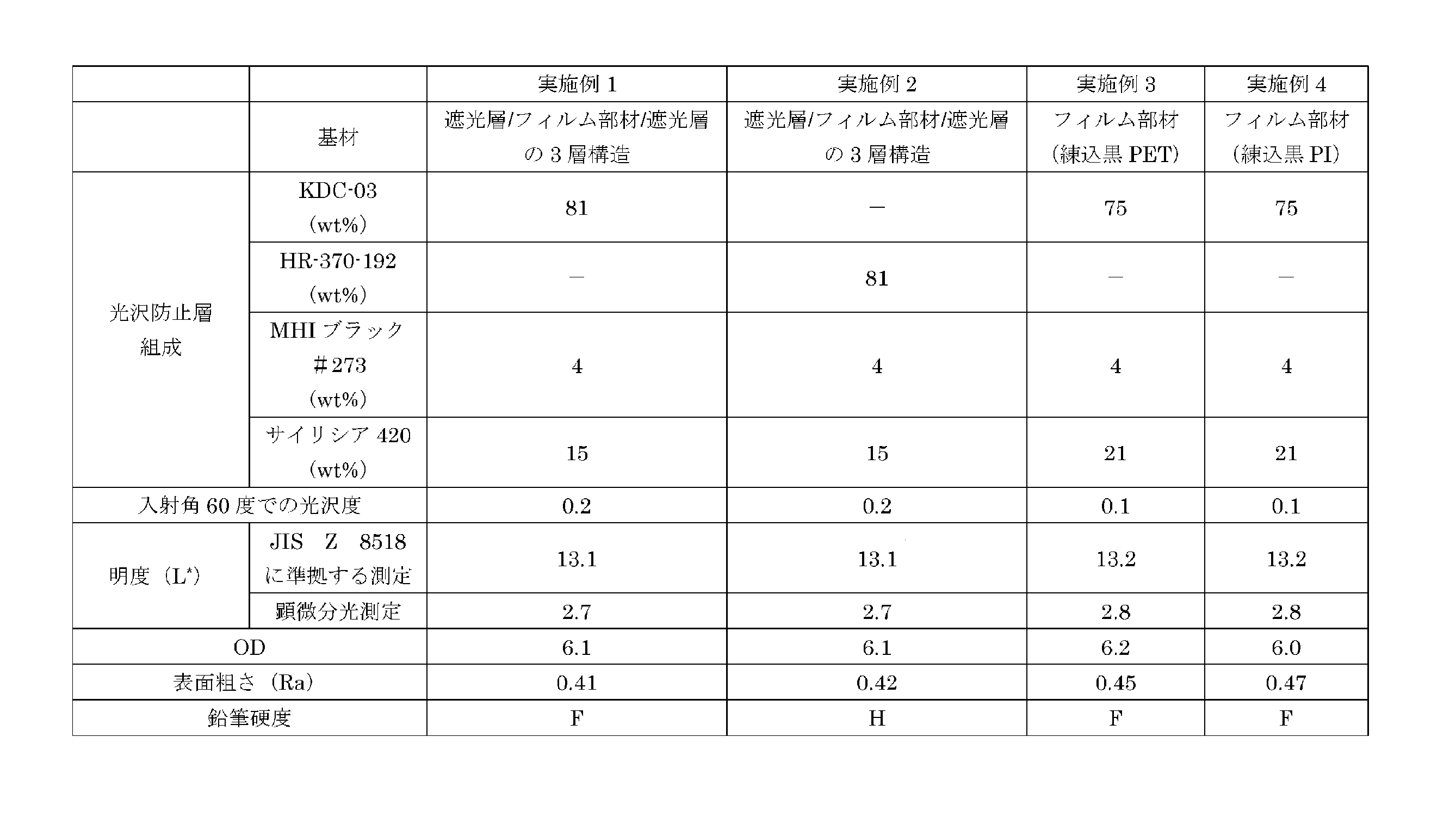


表1~3に示されるように、実施例1~4については、良好な遮光性とOD値とを有する遮光フィルム1、101が得られることが確認された。また、光沢防止層3は光を透過可能に構成されるため、例えば実施例2のように、光沢防止層3の材料として紫外線硬化性樹脂を用いた場合でも、外部から材料中に十分な光量の紫外線を照射でき、優れた硬度を有する光沢防止層3を形成できることが確認された。また実施例1~4は、光沢防止層3の表面が、比較例1~2、4~8の表面層の表面と比べて同等以上の鉛筆硬度(HBよりも高い鉛筆硬度)を有することが確認された。これにより実施例1~4は、光沢防止層3が十分な硬度を有することが確認された。 As shown in Tables 1 to 3, it was confirmed that in Examples 1 to 4, light-shielding films 1 and 101 having good light-shielding properties and OD values were obtained. In addition, since the anti-gloss layer 3 is configured to be light-transmitting, it was confirmed that even when an ultraviolet-curable resin is used as the material for the anti-gloss layer 3, as in Example 2, a sufficient amount of ultraviolet light can be irradiated from the outside into the material, and an anti-gloss layer 3 having excellent hardness can be formed. It was also confirmed that in Examples 1 to 4, the surface of the anti-gloss layer 3 has a pencil hardness equal to or greater than that of the surface layers of Comparative Examples 1 to 2 and 4 to 8 (a pencil hardness higher than HB). This confirmed that the anti-gloss layer 3 in Examples 1 to 4 has sufficient hardness.
これに対して比較例1は、基材に上記透明基材を用いた結果、明度(L*)及びOD値が共に実施例1~4と比較して劣る結果となり、十分な遮光性が得られないことが確認された。また比較例2のように、実施例の光沢防止層に相当する表面層の黒色成分(カーボンブラック)の添加量を比較例1よりも増大させると、遮光性は向上するものの、表面層の表面粗さが低下し、表面層の表面の光沢度が増大することにより、明度(L*)が高くなることが確認された。 In contrast, in Comparative Example 1, the above-mentioned transparent substrate was used as the substrate, and as a result, both the lightness (L * ) and the OD value were inferior to those of Examples 1 to 4, and it was confirmed that sufficient light-shielding properties were not obtained. Also, as in Comparative Example 2, when the amount of the black component (carbon black) added to the surface layer corresponding to the anti-gloss layer of the Examples was increased compared to Comparative Example 1, the light-shielding properties were improved, but the surface roughness of the surface layer was reduced, and the surface gloss of the surface layer was increased, resulting in an increase in lightness (L * ).
また比較例3のように、表面層の黒色成分(カーボンブラック)の添加量が多いと、表面層の材料として紫外線硬化性樹脂を用いた場合、外部から材料中に十分な光量のUVを照射できないために紫外線硬化性樹脂を硬化できず、表面層を形成できないことも判明した。これにより比較例3では、紫外線硬化性樹脂を例えばバインダ樹脂として機能させることは困難であることが確認された。 It was also found that when a large amount of black component (carbon black) is added to the surface layer, as in Comparative Example 3, if ultraviolet-curable resin is used as the material for the surface layer, a sufficient amount of UV light cannot be irradiated from the outside into the material, so the ultraviolet-curable resin cannot be cured and a surface layer cannot be formed. This confirmed that it is difficult to make the ultraviolet-curable resin function as a binder resin, for example, in Comparative Example 3.
また比較例4の結果から、基材に実施例1と同様のものを用いた場合でも、表面層の黒色成分の添加量が少ないと、遮光フィルムの明度(L*)が高くなることが確認された。また比較例5、6の結果から、遮光フィルムの基材に基材2(練込PET)や、基材20(遮光層/フィルム部材/遮光層の3層構造)のいずれを用いても、表面層の黒色成分の添加量が多すぎると、表面層の表面粗さが低下し、表面層の表面の光沢度が増大することにより、明度(L*)が18よりも高くなることが確認された。 Moreover, from the results of Comparative Example 4, it was confirmed that the lightness (L * ) of the light-shielding film increases when the amount of black component added to the surface layer is small, even when the same substrate as in Example 1 is used. Moreover, from the results of Comparative Examples 5 and 6, it was confirmed that whether substrate 2 (kneaded PET) or substrate 20 (three-layer structure of light-shielding layer/film member/light-shielding layer) is used as the substrate of the light-shielding film, when the amount of black component added to the surface layer is too large, the surface roughness of the surface layer decreases and the surface gloss of the surface layer increases, resulting in a lightness (L * ) higher than 18.
また比較例7の結果から、表面層へのフィラー粒子(富士シリシア(株)製「サイリシア420」)の添加量が少なすぎると、表面層の表面のマット性が得られず、当該表面の光沢度が高くなり、遮光フィルムの黒味が低下することが確認された。また比較例8の結果から、表面層へのフィラー粒子(富士シリシア(株)製「サイリシア420」)の添加量が多すぎると、表面層の表面の光沢度は低下するが、粒子の白味が加わることにより、遮光フィルムの黒味が低下することが確認された。以上により、実施例1~4の優位性が確認された。 The results of Comparative Example 7 confirmed that if too little filler particles ("Sylysia 420" manufactured by Fuji Silysia Co., Ltd.) were added to the surface layer, the matte surface of the surface layer was not obtained, the gloss of the surface increased, and the blackness of the light-shielding film decreased. The results of Comparative Example 8 confirmed that if too much filler particles ("Sylysia 420" manufactured by Fuji Silysia Co., Ltd.) were added to the surface layer, the gloss of the surface layer decreased, but the blackness of the light-shielding film decreased due to the whiteness of the particles. From the above, the superiority of Examples 1 to 4 was confirmed.
各実施形態における各構成及びそれらの組み合わせ等は、一例であって、本開示の趣旨から逸脱しない範囲内で、適宜、構成の付加、省略、置換、及びその他の変更が可能である。本開示は、実施形態によって限定されることはなく、特許請求の範囲によってのみ限定される。また、本明細書に開示された各々の態様は、本明細書に開示された他のいかなる特徴とも組み合わせることができる。 The configurations and combinations thereof in each embodiment are merely examples, and additions, omissions, substitutions, and other modifications of the configurations are possible as appropriate without departing from the spirit of this disclosure. This disclosure is not limited to the embodiments, but only by the claims. In addition, each aspect disclosed in this specification may be combined with any other feature disclosed in this specification.
F1~F6 遮光部材
L1~L6 レンズ
1、101 遮光フィルム
2、20 基材
3 光沢防止層
21 フィルム部材
22、23 遮光層
30 バインダ樹脂
31 フィラー粒子
32 着色成分
40 光学部品
41 筐体
F1 to F6 Light-shielding member L1 to L6 Lens 1, 101 Light-shielding film 2, 20 Substrate 3 Anti-gloss layer 21 Film member 22, 23 Light-shielding layer 30 Binder resin 31 Filler particle 32 Coloring component 40 Optical component 41 Housing
Claims (12)
前記基材に重ねて配置され、前記基材とは反対側の表面に凹凸が形成され、前記基材よりも透明な、少なくとも1つの光沢防止層と、を備え、
前記光沢防止層は、バインダ樹脂と、前記バインダ樹脂中に分散されたフィラー粒子と、前記バインダ樹脂中に分散された着色成分と、を含み、
JIS Z 8518に規定される明度である黒味(L*)が、15以下の範囲の値に設定され、又は、顕微分光測定により測定した明度である黒味(L*)が、3.1以下の範囲の値に設定され、
且つ、JIS K 5600:1999に準拠した方法で測定される鉛筆硬度がH又はFに設定され、
光学部品のシャッター間、絞り部材間、及び、複数のレンズ間のうちの少なくともいずれかの間に配置されるギャップ調整部材である、遮光フィルム。 A sheet-like substrate having light-shielding properties and being a resin film;
At least one anti-gloss layer disposed on the substrate, the anti-gloss layer having a textured surface on the surface opposite the substrate and being more transparent than the substrate;
the antigloss layer includes a binder resin, filler particles dispersed in the binder resin, and a coloring component dispersed in the binder resin;
The blackness (L * ) which is the lightness defined in JIS Z 8518 is set to a value in the range of 15 or less, or the blackness (L * ) which is the lightness measured by microspectrophotometric measurement is set to a value in the range of 3.1 or less,
And the pencil hardness measured according to a method in accordance with JIS K 5600:1999 is set to H or F;
A light-shielding film that is a gap adjustment member that is arranged at least between the shutters, the aperture members, and the multiple lenses of optical components.
前記フィルム部材と前記遮光層とのうち、前記遮光層が前記光沢防止層側となるように配置される、請求項1に記載の遮光フィルム。 The substrate includes a film member and at least one light-shielding layer having a higher light-shielding property than the film member and disposed on the film member;
The light-shielding film according to claim 1 , wherein the film member and the light-shielding layer are disposed such that the light-shielding layer is on the antigloss layer side.
前記基材は、前記フィルム部材の両面に重ねて配置された一対の前記遮光層を含む、請求項2に記載の遮光フィルム。 A pair of the antigloss layers is disposed on both sides of the substrate,
The light-shielding film according to claim 2 , wherein the substrate includes a pair of the light-shielding layers disposed in a superimposed manner on both sides of the film member.
前記複数の光学部材と前記遮光部材とを収容する筐体と、を備え、
前記遮光部材が、前記複数の光学部材のうち、隣接する光学部材間に、前記複数の光学部材の光軸を囲むように配置されている、請求項11に記載の光学部品。 A plurality of optical members;
a housing that houses the plurality of optical members and the light blocking member,
The optical component according to claim 11 , wherein the light blocking member is disposed between adjacent optical members among the plurality of optical members so as to surround the optical axes of the plurality of optical members.
Priority Applications (1)
| Application Number | Priority Date | Filing Date | Title |
|---|---|---|---|
| JP2023001951A JP7547520B2 (en) | 2021-03-09 | 2023-01-10 | Light-shielding film, light-shielding member, and optical component |
Applications Claiming Priority (2)
| Application Number | Priority Date | Filing Date | Title |
|---|---|---|---|
| JP2021036983A JP7209758B2 (en) | 2021-03-09 | 2021-03-09 | Light-shielding film and light-shielding member |
| JP2023001951A JP7547520B2 (en) | 2021-03-09 | 2023-01-10 | Light-shielding film, light-shielding member, and optical component |
Related Parent Applications (1)
| Application Number | Title | Priority Date | Filing Date |
|---|---|---|---|
| JP2021036983A Division JP7209758B2 (en) | 2021-03-09 | 2021-03-09 | Light-shielding film and light-shielding member |
Publications (2)
| Publication Number | Publication Date |
|---|---|
| JP2023036980A JP2023036980A (en) | 2023-03-14 |
| JP7547520B2 true JP7547520B2 (en) | 2024-09-09 |
Family
ID=83157563
Family Applications (2)
| Application Number | Title | Priority Date | Filing Date |
|---|---|---|---|
| JP2021036983A Active JP7209758B2 (en) | 2021-03-09 | 2021-03-09 | Light-shielding film and light-shielding member |
| JP2023001951A Active JP7547520B2 (en) | 2021-03-09 | 2023-01-10 | Light-shielding film, light-shielding member, and optical component |
Family Applications Before (1)
| Application Number | Title | Priority Date | Filing Date |
|---|---|---|---|
| JP2021036983A Active JP7209758B2 (en) | 2021-03-09 | 2021-03-09 | Light-shielding film and light-shielding member |
Country Status (3)
| Country | Link |
|---|---|
| JP (2) | JP7209758B2 (en) |
| KR (1) | KR102879161B1 (en) |
| CN (1) | CN115047550B (en) |
Families Citing this family (1)
| Publication number | Priority date | Publication date | Assignee | Title |
|---|---|---|---|---|
| JP2025142506A (en) * | 2024-03-18 | 2025-10-01 | 株式会社ダイセル | Light-shielding film and lens unit |
Citations (2)
| Publication number | Priority date | Publication date | Assignee | Title |
|---|---|---|---|---|
| US20150234098A1 (en) | 2014-02-17 | 2015-08-20 | Kevin D. Lofftus | Light blocking articles having opacifying layers |
| WO2021028974A1 (en) | 2019-08-09 | 2021-02-18 | 株式会社ダイセル | Light-shielding film and method for producing light-shielding film |
Family Cites Families (9)
| Publication number | Priority date | Publication date | Assignee | Title |
|---|---|---|---|---|
| JP2510363B2 (en) * | 1991-06-12 | 1996-06-26 | 新日本製鐵株式会社 | Matte black surface treated steel plate |
| EP2183622A1 (en) | 2007-07-25 | 2010-05-12 | Nippon Shokubai Co., Ltd. | Light-shielding film |
| JP4735672B2 (en) * | 2008-06-27 | 2011-07-27 | 住友金属鉱山株式会社 | Film-shaped shading plate, and aperture, aperture device for adjusting light quantity, or shutter using the same |
| US8591044B2 (en) | 2009-08-21 | 2013-11-26 | 3M Innovative Properties Company | Pavement markings, reflective elements, and methods of making microspheres |
| US20120202081A1 (en) * | 2009-10-29 | 2012-08-09 | Junko Takahashi | Light-blocking member for optical instrument |
| WO2013126361A1 (en) | 2012-02-22 | 2013-08-29 | 3M Innovative Properties Company | Microsphere articles and transfer articles |
| JP6650686B2 (en) * | 2015-05-21 | 2020-02-19 | 株式会社きもと | Light shielding member |
| WO2017217429A1 (en) | 2016-06-14 | 2017-12-21 | 株式会社クラレ | Black film |
| JP6593966B2 (en) * | 2016-06-29 | 2019-10-23 | ソマール株式会社 | Light shielding member for optical device |
-
2021
- 2021-03-09 JP JP2021036983A patent/JP7209758B2/en active Active
-
2022
- 2022-02-16 KR KR1020220020450A patent/KR102879161B1/en active Active
- 2022-02-22 CN CN202210161244.2A patent/CN115047550B/en active Active
-
2023
- 2023-01-10 JP JP2023001951A patent/JP7547520B2/en active Active
Patent Citations (2)
| Publication number | Priority date | Publication date | Assignee | Title |
|---|---|---|---|---|
| US20150234098A1 (en) | 2014-02-17 | 2015-08-20 | Kevin D. Lofftus | Light blocking articles having opacifying layers |
| WO2021028974A1 (en) | 2019-08-09 | 2021-02-18 | 株式会社ダイセル | Light-shielding film and method for producing light-shielding film |
Also Published As
| Publication number | Publication date |
|---|---|
| JP2023036980A (en) | 2023-03-14 |
| JP2022137471A (en) | 2022-09-22 |
| KR102879161B1 (en) | 2025-10-30 |
| JP7209758B2 (en) | 2023-01-20 |
| CN115047550A (en) | 2022-09-13 |
| KR20220126632A (en) | 2022-09-16 |
| CN115047550B (en) | 2024-08-16 |
Similar Documents
| Publication | Publication Date | Title |
|---|---|---|
| JP6525078B2 (en) | Optical filter and imaging device | |
| JP7009677B1 (en) | Optical filter, its manufacturing method and optical module | |
| KR102708161B1 (en) | Light-shielding film for optical devices and laminated light-shielding film for optical devices, and light-shielding ring for optical devices using the same, aperture member for optical devices, shutter member for optical devices, lens unit and camera module | |
| JP7044951B2 (en) | Optical filter, its manufacturing method and optical module | |
| JP7547520B2 (en) | Light-shielding film, light-shielding member, and optical component | |
| KR101530452B1 (en) | Methods for manufacturing light-diffusing element and polarizing plate with light-diffusing element, and light-diffusing element and polarizing plate with light-diffusing element obtained by same methods | |
| JP7009678B1 (en) | Optical filter, its manufacturing method and optical module | |
| JP7044952B2 (en) | Optical filter, its manufacturing method and optical module | |
| JP7493640B2 (en) | Light-shielding film, optical component, and method for manufacturing light-shielding film | |
| KR20190133007A (en) | Laminated shielding film, and shielding ring for optical device, lens unit and camera module using same | |
| US20090086317A1 (en) | Reflective Screen | |
| CN105190368A (en) | Manufacturing method of light diffusing element and light diffusing element | |
| CN120428367A (en) | Display screen film material and manufacturing method thereof, module light board, display module | |
| JP2005275339A (en) | Manufacturing method of lens sheet having light-shielding band, lens sheet and screen |
Legal Events
| Date | Code | Title | Description |
|---|---|---|---|
| A521 | Request for written amendment filed |
Free format text: JAPANESE INTERMEDIATE CODE: A523 Effective date: 20230216 |
|
| A621 | Written request for application examination |
Free format text: JAPANESE INTERMEDIATE CODE: A621 Effective date: 20230216 |
|
| A977 | Report on retrieval |
Free format text: JAPANESE INTERMEDIATE CODE: A971007 Effective date: 20231128 |
|
| A131 | Notification of reasons for refusal |
Free format text: JAPANESE INTERMEDIATE CODE: A131 Effective date: 20231205 |
|
| A521 | Request for written amendment filed |
Free format text: JAPANESE INTERMEDIATE CODE: A523 Effective date: 20240130 |
|
| A131 | Notification of reasons for refusal |
Free format text: JAPANESE INTERMEDIATE CODE: A131 Effective date: 20240507 |
|
| A521 | Request for written amendment filed |
Free format text: JAPANESE INTERMEDIATE CODE: A523 Effective date: 20240528 |
|
| TRDD | Decision of grant or rejection written | ||
| A01 | Written decision to grant a patent or to grant a registration (utility model) |
Free format text: JAPANESE INTERMEDIATE CODE: A01 Effective date: 20240806 |
|
| A61 | First payment of annual fees (during grant procedure) |
Free format text: JAPANESE INTERMEDIATE CODE: A61 Effective date: 20240828 |
|
| R150 | Certificate of patent or registration of utility model |
Ref document number: 7547520 Country of ref document: JP Free format text: JAPANESE INTERMEDIATE CODE: R150 |