JP7539552B2 - Information processing device, control method, program, and storage medium - Google Patents
Information processing device, control method, program, and storage medium Download PDFInfo
- Publication number
- JP7539552B2 JP7539552B2 JP2023506395A JP2023506395A JP7539552B2 JP 7539552 B2 JP7539552 B2 JP 7539552B2 JP 2023506395 A JP2023506395 A JP 2023506395A JP 2023506395 A JP2023506395 A JP 2023506395A JP 7539552 B2 JP7539552 B2 JP 7539552B2
- Authority
- JP
- Japan
- Prior art keywords
- water surface
- data
- ship
- obstacle
- point cloud
- Prior art date
- Legal status (The legal status is an assumption and is not a legal conclusion. Google has not performed a legal analysis and makes no representation as to the accuracy of the status listed.)
- Active
Links
Images


Classifications
-
- G—PHYSICS
- G01—MEASURING; TESTING
- G01S—RADIO DIRECTION-FINDING; RADIO NAVIGATION; DETERMINING DISTANCE OR VELOCITY BY USE OF RADIO WAVES; LOCATING OR PRESENCE-DETECTING BY USE OF THE REFLECTION OR RERADIATION OF RADIO WAVES; ANALOGOUS ARRANGEMENTS USING OTHER WAVES
- G01S17/00—Systems using the reflection or reradiation of electromagnetic waves other than radio waves, e.g. lidar systems
- G01S17/86—Combinations of lidar systems with systems other than lidar, radar or sonar, e.g. with direction finders
-
- G—PHYSICS
- G01—MEASURING; TESTING
- G01S—RADIO DIRECTION-FINDING; RADIO NAVIGATION; DETERMINING DISTANCE OR VELOCITY BY USE OF RADIO WAVES; LOCATING OR PRESENCE-DETECTING BY USE OF THE REFLECTION OR RERADIATION OF RADIO WAVES; ANALOGOUS ARRANGEMENTS USING OTHER WAVES
- G01S7/00—Details of systems according to groups G01S13/00, G01S15/00, G01S17/00
- G01S7/48—Details of systems according to groups G01S13/00, G01S15/00, G01S17/00 of systems according to group G01S17/00
- G01S7/4808—Evaluating distance, position or velocity data
-
- G—PHYSICS
- G01—MEASURING; TESTING
- G01S—RADIO DIRECTION-FINDING; RADIO NAVIGATION; DETERMINING DISTANCE OR VELOCITY BY USE OF RADIO WAVES; LOCATING OR PRESENCE-DETECTING BY USE OF THE REFLECTION OR RERADIATION OF RADIO WAVES; ANALOGOUS ARRANGEMENTS USING OTHER WAVES
- G01S17/00—Systems using the reflection or reradiation of electromagnetic waves other than radio waves, e.g. lidar systems
- G01S17/02—Systems using the reflection of electromagnetic waves other than radio waves
- G01S17/04—Systems determining the presence of a target
-
- G—PHYSICS
- G01—MEASURING; TESTING
- G01S—RADIO DIRECTION-FINDING; RADIO NAVIGATION; DETERMINING DISTANCE OR VELOCITY BY USE OF RADIO WAVES; LOCATING OR PRESENCE-DETECTING BY USE OF THE REFLECTION OR RERADIATION OF RADIO WAVES; ANALOGOUS ARRANGEMENTS USING OTHER WAVES
- G01S17/00—Systems using the reflection or reradiation of electromagnetic waves other than radio waves, e.g. lidar systems
- G01S17/02—Systems using the reflection of electromagnetic waves other than radio waves
- G01S17/06—Systems determining position data of a target
- G01S17/08—Systems determining position data of a target for measuring distance only
-
- G—PHYSICS
- G01—MEASURING; TESTING
- G01S—RADIO DIRECTION-FINDING; RADIO NAVIGATION; DETERMINING DISTANCE OR VELOCITY BY USE OF RADIO WAVES; LOCATING OR PRESENCE-DETECTING BY USE OF THE REFLECTION OR RERADIATION OF RADIO WAVES; ANALOGOUS ARRANGEMENTS USING OTHER WAVES
- G01S17/00—Systems using the reflection or reradiation of electromagnetic waves other than radio waves, e.g. lidar systems
- G01S17/02—Systems using the reflection of electromagnetic waves other than radio waves
- G01S17/06—Systems determining position data of a target
- G01S17/42—Simultaneous measurement of distance and other co-ordinates
-
- G—PHYSICS
- G01—MEASURING; TESTING
- G01S—RADIO DIRECTION-FINDING; RADIO NAVIGATION; DETERMINING DISTANCE OR VELOCITY BY USE OF RADIO WAVES; LOCATING OR PRESENCE-DETECTING BY USE OF THE REFLECTION OR RERADIATION OF RADIO WAVES; ANALOGOUS ARRANGEMENTS USING OTHER WAVES
- G01S17/00—Systems using the reflection or reradiation of electromagnetic waves other than radio waves, e.g. lidar systems
- G01S17/88—Lidar systems specially adapted for specific applications
- G01S17/89—Lidar systems specially adapted for specific applications for mapping or imaging
-
- G—PHYSICS
- G01—MEASURING; TESTING
- G01S—RADIO DIRECTION-FINDING; RADIO NAVIGATION; DETERMINING DISTANCE OR VELOCITY BY USE OF RADIO WAVES; LOCATING OR PRESENCE-DETECTING BY USE OF THE REFLECTION OR RERADIATION OF RADIO WAVES; ANALOGOUS ARRANGEMENTS USING OTHER WAVES
- G01S17/00—Systems using the reflection or reradiation of electromagnetic waves other than radio waves, e.g. lidar systems
- G01S17/88—Lidar systems specially adapted for specific applications
- G01S17/93—Lidar systems specially adapted for specific applications for anti-collision purposes
-
- G—PHYSICS
- G01—MEASURING; TESTING
- G01S—RADIO DIRECTION-FINDING; RADIO NAVIGATION; DETERMINING DISTANCE OR VELOCITY BY USE OF RADIO WAVES; LOCATING OR PRESENCE-DETECTING BY USE OF THE REFLECTION OR RERADIATION OF RADIO WAVES; ANALOGOUS ARRANGEMENTS USING OTHER WAVES
- G01S17/00—Systems using the reflection or reradiation of electromagnetic waves other than radio waves, e.g. lidar systems
- G01S17/88—Lidar systems specially adapted for specific applications
- G01S17/95—Lidar systems specially adapted for specific applications for meteorological use
-
- G—PHYSICS
- G01—MEASURING; TESTING
- G01S—RADIO DIRECTION-FINDING; RADIO NAVIGATION; DETERMINING DISTANCE OR VELOCITY BY USE OF RADIO WAVES; LOCATING OR PRESENCE-DETECTING BY USE OF THE REFLECTION OR RERADIATION OF RADIO WAVES; ANALOGOUS ARRANGEMENTS USING OTHER WAVES
- G01S7/00—Details of systems according to groups G01S13/00, G01S15/00, G01S17/00
- G01S7/48—Details of systems according to groups G01S13/00, G01S15/00, G01S17/00 of systems according to group G01S17/00
- G01S7/4802—Details of systems according to groups G01S13/00, G01S15/00, G01S17/00 of systems according to group G01S17/00 using analysis of echo signal for target characterisation; Target signature; Target cross-section
-
- G—PHYSICS
- G01—MEASURING; TESTING
- G01S—RADIO DIRECTION-FINDING; RADIO NAVIGATION; DETERMINING DISTANCE OR VELOCITY BY USE OF RADIO WAVES; LOCATING OR PRESENCE-DETECTING BY USE OF THE REFLECTION OR RERADIATION OF RADIO WAVES; ANALOGOUS ARRANGEMENTS USING OTHER WAVES
- G01S7/00—Details of systems according to groups G01S13/00, G01S15/00, G01S17/00
- G01S7/48—Details of systems according to groups G01S13/00, G01S15/00, G01S17/00 of systems according to group G01S17/00
- G01S7/497—Means for monitoring or calibrating
-
- Y—GENERAL TAGGING OF NEW TECHNOLOGICAL DEVELOPMENTS; GENERAL TAGGING OF CROSS-SECTIONAL TECHNOLOGIES SPANNING OVER SEVERAL SECTIONS OF THE IPC; TECHNICAL SUBJECTS COVERED BY FORMER USPC CROSS-REFERENCE ART COLLECTIONS [XRACs] AND DIGESTS
- Y02—TECHNOLOGIES OR APPLICATIONS FOR MITIGATION OR ADAPTATION AGAINST CLIMATE CHANGE
- Y02A—TECHNOLOGIES FOR ADAPTATION TO CLIMATE CHANGE
- Y02A90/00—Technologies having an indirect contribution to adaptation to climate change
- Y02A90/30—Assessment of water resources
Landscapes
- Engineering & Computer Science (AREA)
- Physics & Mathematics (AREA)
- Radar, Positioning & Navigation (AREA)
- Remote Sensing (AREA)
- Computer Networks & Wireless Communication (AREA)
- General Physics & Mathematics (AREA)
- Electromagnetism (AREA)
- Optical Radar Systems And Details Thereof (AREA)
Description
本開示は、船舶において計測したデータの処理に関する。 This disclosure relates to processing data measured on ships.
従来から、レーザスキャナなどの計測装置を用いて計測した周辺物体の形状データを、予め周辺物体の形状が記憶された地図情報と照合(マッチング)することで、移動体の自己位置を推定する技術が知られている。例えば、特許文献1には、空間を所定の規則で分割したボクセル中における検出物が静止物か移動物かを判定し、静止物が存在するボクセルを対象として地図情報と計測データとのマッチングを行う自律移動システムが開示されている。また、特許文献2には、ボクセル毎の静止物体の平均ベクトルと共分散行列とを含むボクセルデータとライダが出力する点群データとの照合により自己位置推定を行うスキャンマッチング手法が開示されている。さらに、特許文献3には、船舶の自動着岸を行う自動着岸装置において、ライダから照射される光が着岸位置の周囲の物体に反射してライダにより受光できるように、船舶の姿勢を変化させる制御を行う手法が記載されている。Conventionally, a technique for estimating the self-position of a moving object by collating (matching) shape data of surrounding objects measured using a measuring device such as a laser scanner with map information in which the shapes of surrounding objects are stored in advance has been known. For example,
昨今、自動車分野だけでなく、船舶においても、自動操船システムの検討が進められており、安全な自動操船には精度の良い自己位置推定は同様に重要である。外洋では周辺に構造物が少ないためGNSS(Global Navigation Satellite System)により自己位置を測位可能であるが、都市部の沿岸や河川では高層ビル等が隣接するため、受信衛星数の低下やマルチパスなどによりGNSS電波の受信環境は悪く、精度の良い測位はできないことが多い。よって、船舶の場合においても、上記のスキャンマッチングによる高精度な位置推定が好適に適用される。Recently, automatic ship-steering systems have been studied not only in the automotive field but also in ships, and accurate self-location estimation is equally important for safe automatic ship-steering. In the open sea, there are few structures in the vicinity, so self-location can be determined using the Global Navigation Satellite System (GNSS). However, in urban coasts and rivers, where high-rise buildings are adjacent, the reception environment for GNSS radio waves is poor due to a reduced number of receiving satellites and multipath, and accurate positioning is often not possible. Therefore, in the case of ships, the above-mentioned high-precision position estimation by scan matching is preferably applied.
一方、船舶にライダを搭載すると、下方向に向いたライダのビームの一部が水面で反射し、実際には存在しない場所からの検出データが得られてしまう。そのような水面反射によるデータは誤検出(誤警報)データであり、自己位置推定の精度に影響を与える。検出されたデータが誤検出データであるか否かを判定するためには、水面の高さを高精度で推定することが必要となる。On the other hand, when a lidar is installed on a ship, part of the lidar's beam pointing downward is reflected by the water surface, resulting in detection data from locations that do not actually exist. Such data reflected by the water surface is false detection (false alarm) data, which affects the accuracy of self-location estimation. In order to determine whether the detected data is false detection data or not, it is necessary to estimate the water surface height with high accuracy.
本開示は、上記のような課題を解決するためになされたものであり、水面の高さを高精度に推定することが可能な情報処理装置を提供することを主な目的とする。 This disclosure has been made to solve the problems described above, and its main objective is to provide an information processing device capable of estimating the water surface height with high accuracy.
請求項に記載の発明は、情報処理装置であって、船舶に設けられた計測装置が生成する点群データを取得する点群データ取得手段と、前記点群データに基づいて、前記船舶の自己位置を推定する自己位置推定手段と、岸の位置を取得する岸位置取得手段と、前記船舶の自己位置及び前記岸の位置に基づいて、前記岸から第1の所定距離離れており、かつ、前記船舶の自己位置から第2の所定距離以内の位置の点群データを、水面において反射されることで計測された水面反射データとして抽出する水面反射データ抽出手段と、前記水面反射データに基づき、水面高さを算出する水面高さ算出手段と、を有する。
The invention described in the claims is an information processing device comprising: a point cloud data acquisition means for acquiring point cloud data generated by a measuring device installed on a ship; a self-position estimation means for estimating the ship's own position based on the point cloud data; a shore position acquisition means for acquiring the position of the shore; a water surface reflection data extraction means for extracting point cloud data of a position that is a first predetermined distance from the shore and within a second predetermined distance from the ship's own position based on the ship's own position and the position of the shore as water surface reflection data measured by reflection on the water surface; and a water surface height calculation means for calculating the water surface height based on the water surface reflection data.
また、請求項に記載の発明は、コンピュータが実行する制御方法であって、船舶に設けられた計測装置が生成する点群データを取得し、前記点群データに基づいて、前記船舶の自己位置を推定し、岸の位置を取得し、前記船舶の自己位置及び前記岸の位置に基づいて、前記岸から第1の所定距離離れており、かつ、前記船舶の自己位置から第2の所定距離以内の位置の点群データを、水面において反射されることで計測された水面反射データとして抽出し、前記水面反射データに基づき、水面高さを算出する。
The invention described in the claims is a control method executed by a computer, which acquires point cloud data generated by a measuring device installed on a ship, estimates the ship's own position based on the point cloud data, acquires the position of the shore, and based on the ship's own position and the position of the shore, extracts point cloud data of a position that is a first predetermined distance from the shore and within a second predetermined distance from the ship's own position as water surface reflection data measured by reflection on the water surface, and calculates the water surface height based on the water surface reflection data.
また、請求項に記載の発明は、プログラムであって、船舶に設けられた計測装置が生成する点群データを取得し、前記点群データに基づいて、前記船舶の自己位置を推定し、岸の位置を取得し、前記船舶の自己位置及び前記岸の位置に基づいて、前記岸から第1の所定距離離れており、かつ、前記船舶の自己位置から第2の所定距離以内の位置の点群データを、水面において反射されることで計測された水面反射データとして抽出し、前記水面反射データに基づき、水面高さを算出する処理をコンピュータに実行させる。
The invention described in the claims is also a program that causes a computer to execute a process of acquiring point cloud data generated by a measuring device installed on a ship , estimating the ship's own position based on the point cloud data, acquiring the position of the shore, extracting point cloud data of a position that is a first predetermined distance from the shore and within a second predetermined distance from the ship's own position based on the ship's own position and the position of the shore as water surface reflection data measured by reflection on the water surface, and calculating the water surface height based on the water surface reflection data.
本発明の1つの好適な実施形態では、情報処理装置は、船舶に設けられた計測装置が生成する点群データを取得する点群データ取得手段と、岸から所定距離離れているデータであり、前記計測装置による計測位置から所定距離以内の位置を計測したデータを、水面において反射されることで計測された水面反射データとして抽出する水面反射データ抽出手段と、前記水面反射データに基づき、水面高さを算出する水面高さ算出手段と、を有する。In one preferred embodiment of the present invention, the information processing device has a point cloud data acquisition means for acquiring point cloud data generated by a measuring device installed on the ship, a water surface reflection data extraction means for extracting data measured at a position a predetermined distance away from the shore and within a predetermined distance from the measurement position by the measuring device as water surface reflection data measured by reflection on the water surface, and a water surface height calculation means for calculating the water surface height based on the water surface reflection data.
上記の情報処理装置では、点群データ取得手段は、船舶に設けられた計測装置が生成する点群データを取得する。水面反射データ抽出手段は、岸から所定距離離れているデータであり、計測装置による計測位置から所定距離以内の位置を計測したデータを、水面において反射されることで計測された水面反射データとして抽出する。そして、水面高さ算出手段は、水面反射データに基づき、水面高さを算出する。これにより、水面反射データを用いて、水面高さを高精度で算出することができる。 In the above information processing device, the point cloud data acquisition means acquires point cloud data generated by a measuring device installed on the ship. The water surface reflection data extraction means extracts data that is a predetermined distance away from the shore and that is measured at a position within a predetermined distance from the measurement position by the measuring device as water surface reflection data measured by reflection on the water surface. Then, the water surface height calculation means calculates the water surface height based on the water surface reflection data. In this way, the water surface reflection data can be used to calculate the water surface height with high accuracy.
上記の情報処理装置の一態様では、前記水面高さ算出手段は、前記水面反射データの高さ方向の値の平均を前記水面高さとして算出する。他の一態様では、前記水面高さ算出手段は、前記水面反射データの高さ方向の値の平均及び分散を算出し、前記分散が所定値未満である場合に、前記平均を前記水面高さとして算出する。In one aspect of the information processing device, the water surface height calculation means calculates the average of the height direction values of the water surface reflection data as the water surface height. In another aspect, the water surface height calculation means calculates the average and variance of the height direction values of the water surface reflection data, and if the variance is less than a predetermined value, calculates the average as the water surface height.
上記の情報処理装置の他の一態様は、前記計測位置及び前記水面高さに基づいて探索範囲を設定し、前記探索範囲に属する点群データに基づいて、障害物及び引き波の少なくとも一方を検出する検出手段を備える。この態様では、水面高さを用いて、障害物や引き波を検出することができる。Another aspect of the information processing device described above includes a detection means for setting a search range based on the measurement position and the water surface height, and detecting at least one of an obstacle and an undertow based on point cloud data belonging to the search range. In this aspect, the obstacle or undertow can be detected using the water surface height.
上記の情報処理装置の他の一態様では、前記検出手段は、前記探索範囲に属する点群データが線状か否かを判定し、線状と判定された点群データが所定時間にわたり存在する場合に、当該線状の点群データを引き波として検出し、前記探索範囲に属する点群データがかたまりを形成しているか否かを判定し、かたまりと判定された点群データが所定時間にわたり存在する場合に、当該かたまりを障害物として検出する。In another aspect of the above information processing device, the detection means determines whether the point cloud data belonging to the search range is linear or not, and if the point cloud data determined to be linear exists for a predetermined time, detects the linear point cloud data as an undertow, determines whether the point cloud data belonging to the search range forms a lump, and if the point cloud data determined to be a lump exists for a predetermined time, detects the lump as an obstacle.
上記の情報処理装置の他の一態様では、前記検出手段は、前記水面反射データの高さ方向の値の分散に基づいて、前記探索範囲の高さ範囲を変化させる。これにより、波の高さに応じて、適切な探索範囲を設定することができる。In another aspect of the information processing device, the detection means changes the height range of the search range based on the variance of the height direction values of the water surface reflection data. This makes it possible to set an appropriate search range depending on the wave height.
本発明の他の好適な実施形態では、コンピュータが実行する制御方法は、船舶に設けられた計測装置が生成する点群データを取得し、岸から所定距離離れているデータであり、前記計測装置による計測位置から所定距離以内の位置を計測したデータを、水面において反射されることで計測された水面反射データとして抽出し、前記水面反射データに基づき、水面高さを算出する。これにより、水面反射データを用いて、水面高さを高精度で算出することができる。In another preferred embodiment of the present invention, a control method executed by a computer acquires point cloud data generated by a measuring device installed on a ship, extracts data that is a predetermined distance away from the shore and that measures a position within a predetermined distance from the measurement position of the measuring device as water surface reflection data measured by reflection on the water surface, and calculates the water surface height based on the water surface reflection data. This makes it possible to calculate the water surface height with high accuracy using the water surface reflection data.
本発明の他の好適な実施形態では、プログラムは、船舶に設けられた計測装置が生成する点群データを取得し、岸から所定距離離れているデータであり、前記計測装置による計測位置から所定距離以内の位置を計測したデータを、水面において反射されることで計測された水面反射データとして抽出し、前記水面反射データに基づき、水面高さを算出する処理をコンピュータに実行させる。このプログラムをコンピュータで実行することにより、上記の情報処理装置を実現することができる。このプログラムは記憶媒体に記憶して取り扱うことができる。 In another preferred embodiment of the present invention, the program acquires point cloud data generated by a measuring device installed on a ship, extracts data that is a predetermined distance away from the shore and that measures a position within a predetermined distance from the measurement position of the measuring device as water surface reflection data measured by reflection on the water surface, and has the computer execute a process to calculate the water surface height based on the water surface reflection data. By executing this program on a computer, the above-mentioned information processing device can be realized. This program can be stored in a storage medium and handled.
以下、図面を参照して本発明の好適な実施例について説明する。なお、任意の記号の上に「^」または「-」が付された文字を、本明細書では便宜上、「A^」または「A-」(「A」は任意の文字)と表す。 Hereinafter, preferred embodiments of the present invention will be described with reference to the drawings. For the sake of convenience, any symbol followed by "^" or "-" will be expressed as "A^" or " A- " (where "A" is any character) in this specification.
(1)運転支援システムの概要
図1は、本実施例に係る運転支援システムの概略構成である。運転支援システムは、移動体である船舶と共に移動する情報処理装置1と、当該船舶に搭載されたセンサ群2とを有する。以後では、情報処理装置1と共に移動する船舶を「対象船舶」とも呼ぶ。
(1) Overview of driving assistance system
Fig. 1 shows a schematic configuration of a driving assistance system according to the present embodiment. The driving assistance system includes an
情報処理装置1は、センサ群2と電気的に接続し、センサ群2に含まれる各種センサの出力に基づき、情報処理装置1が設けられた対象船舶の位置(「自己位置」とも呼ぶ。)の推定を行う。そして、情報処理装置1は、自己位置の推定結果に基づき、対象船舶の自動運転制御等の運転支援を行う。運転支援には、自動着岸などの着岸支援も含まれる。ここで、「着岸」とは、岸壁に対象船舶を着ける場合の他、桟橋等の構造体に対象船舶を着ける場合も含まれる。情報処理装置1は、対象船舶に設けられたナビゲーション装置であってもよく、船舶に内蔵された電子制御装置であってもよい。The
また、情報処理装置1は、ボクセルデータ「VD」を含む地図データベース(DB:DataBase)10を記憶する。ボクセルデータVDは、3次元空間の最小単位となる立方体(正規格子)を示すボクセルごとに静止構造物の位置情報等を記録したデータである。ボクセルデータVDは、各ボクセル内の静止構造物の計測された点群データを正規分布により表したデータを含み、後述するように、NDT(Normal Distributions Transform)を用いたスキャンマッチングに用いられる。情報処理装置1は、NDTスキャンマッチングにより、例えば、対象船舶の平面上の位置、高さ位置、ヨー角、ピッチ角及びロール角の推定を行う。なお、特に言及がない限り、自己位置は、対象船舶のヨー角などの姿勢角も含まれるものとする。The
センサ群2は、対象船舶に設けられた種々の外界センサ及び内界センサを含んでいる。本実施例では、センサ群2は、ライダ(Lidar:Light Detection and Ranging、または、Laser Illuminated Detection And Ranging)3と、対象船舶の速度を検出する速度センサ4と、GPS(Global Positioning Satellite)受信機5と、3軸方向における対象船舶の加速度及び角速度を計測する慣性計測装置(IMU:Inertial Measurement Unit)6とを含んでいる。The
ライダ3は、水平方向および垂直方向の所定の角度範囲に対してパルスレーザを出射することで、外界に存在する物体までの距離を離散的に測定し、当該物体の位置を示す3次元の点群データを生成する。この場合、ライダ3は、照射方向を変えながらレーザ光を照射する照射部と、照射したレーザ光の反射光(散乱光)を受光する受光部と、受光部が出力する受光信号に基づくスキャンデータ(点群データを構成する点であり、以後では「計測点」と呼ぶ。)を出力する出力部とを有する。計測点は、受光部が受光したレーザ光に対応する照射方向と、上述の受光信号に基づき特定される当該レーザ光の応答遅延時間とに基づき生成される。なお、一般的に、対象物までの距離が近いほどライダの距離測定値の精度は高く、距離が遠いほど精度は低い。ライダ3は、本発明における「計測装置」の一例である。速度センサ4は、例えば、ドップラーを利用した速度計であってもよく、GNSSを利用した速度計であってもよい。The
なお、センサ群2は、GPS受信機5に代えて、GPS以外のGNSSの測位結果を生成する受信機を有してもよい。
In addition, the
(2)情報処理装置の構成
図2は、情報処理装置1のハードウェア構成の一例を示すブロック図である。情報処理装置1は、主に、インターフェース11と、メモリ12と、コントローラ13と、を有する。これらの各要素は、バスラインを介して相互に接続されている。
(2) Configuration of the information processing device
2 is a block diagram showing an example of a hardware configuration of the
インターフェース11は、情報処理装置1と外部装置とのデータの授受に関するインターフェース動作を行う。本実施例では、インターフェース11は、ライダ3、速度センサ4、GPS受信機5及びIMU6などのセンサ群2の各センサから出力データを取得し、コントローラ13へ供給する。また、インターフェース11は、例えば、コントローラ13が生成した対象船舶の制御に関する信号を、対象船舶の運転を制御する対象船舶の各構成要素に供給する。例えば、対象船舶は、エンジンや電気モータなどの駆動源と、駆動源の駆動力に基づき進行方向の推進力を生成するスクリューと、駆動源の駆動力に基づき横方向の推進力を生成するスラスターと、船舶の進行方向を自在に定めるための機構である舵等とを備える。そして、自動着岸などの自動運転時には、インターフェース11は、コントローラ13が生成した制御信号を、これらの各構成要素に供給する。なお、対象船舶に電子制御装置が設けられている場合には、インターフェース11は、当該電子制御装置に対し、コントローラ13が生成した制御信号を供給する。インターフェース11は、無線通信を行うためのネットワークアダプタなどのワイヤレスインターフェースであってもよく、ケーブル等により外部装置と接続するためのハードウェアインターフェースであってもよい。また、インターフェース11は、入力装置、表示装置、音出力装置等の種々の周辺装置とのインターフェース動作を行ってもよい。The
メモリ12は、RAM(Random Access Memory)、ROM(Read Only Memory)、ハードディスクドライブ、フラッシュメモリなどの各種の揮発性メモリ及び不揮発性メモリにより構成される。メモリ12は、コントローラ13が所定の処理を実行するためのプログラムが記憶される。なお、コントローラ13が実行するプログラムは、メモリ12以外の記憶媒体に記憶されてもよい。The
また、メモリ12は、ボクセルデータVDを含む地図DB10を記憶する。地図DB10には、ボクセルデータVDの他、例えば、着岸場所(岸、桟橋を含む)に関する情報、船舶が移動可能な水路に関する情報などが含まれている。なお、地図DB10は、インターフェース11を介して情報処理装置1と接続されたハードディスクなどの情報処理装置1の外部の記憶装置に記憶されてもよい。上記の記憶装置は、情報処理装置1と通信を行うサーバ装置であってもよい。また、上記の記憶装置は、複数の装置から構成されてもよい。また、地図DB10は、定期的に更新されてもよい。この場合、例えば、コントローラ13は、インターフェース11を介し、地図情報を管理するサーバ装置から、自己位置が属するエリアに関する部分地図情報を受信し、地図DB10に反映させる。
The
また、メモリ12には、地図DB10の他、本実施例において情報処理装置1が実行する処理に必要な情報が記憶される。例えば、メモリ12には、ライダ3が1周期分の走査を行った場合に得られる点群データに対してダウンサンプリングを行う場合のダウンサンプリングのサイズの設定に用いられる情報が記憶される。In addition to the
コントローラ13は、CPU(Central Processing Unit)、GPU(Graphics Processing Unit)、TPU(Tensor Processing Unit)などの1又は複数のプロセッサを含み、情報処理装置1の全体を制御する。この場合、コントローラ13は、メモリ12等に記憶されたプログラムを実行することで、自己位置推定及び運転支援等に関する処理を行う。The
また、コントローラ13は、機能的には、自己位置推定部15と、障害物/引き波検出部16とを有する。そして、コントローラ13は、「点群データ取得手段」、「水面反射データ抽出手段」、「水面高さ算出手段」、「検出手段」及びプログラムを実行するコンピュータ等として機能する。Functionally, the
自己位置推定部15は、ライダ3の出力に基づく点群データと、当該点群データが属するボクセルに対応するボクセルデータVDとに基づき、NDTに基づくスキャンマッチング(NDTスキャンマッチング)を行うことで、自己位置の推定を行う。ここで、自己位置推定部15による処理対象となる点群データは、ライダ3が生成した点群データであってもよく、当該点群データをダウンサンプリング処理した後の点群データであってもよい。The self-
障害物/引き波検出部16は、ライダ3が出力した点群データを用いて、船舶の周辺の障害物や引き波を検出する。The obstacle/
(3)自己位置推定
次に、自己位置推定部15が実行するNDTスキャンマッチングに基づく自己位置推定に関する説明を行う。
(3) Self-location estimation
Next, the self-location estimation based on NDT scan matching executed by the self-
図3は、自己位置推定部15が推定すべき自己位置を3次元直交座標で表した図である。図3に示すように、xyzの3次元直交座標上で定義された平面での自己位置は、座標「(x、y、z)」、対象船舶のロール角「φ」、ピッチ角「θ」、ヨー角(方位)「ψ」により表される。ここでは、ロール角φは、対象船舶の進行方向を軸とした回転角、ピッチ角θは、xy平面に対する対象船舶の進行方向の仰角、ヨー角ψは、対象船舶の進行方向とx軸とのなす角として定義されている。座標(x、y、z)は、例えば緯度、経度、標高の組合せに相当する絶対位置、あるいは所定地点を原点とした位置を示すワールド座標である。そして、自己位置推定部15は、これらのx、y、z、φ、θ、ψを推定パラメータとする自己位置推定を行う。
Figure 3 is a diagram showing the self-position to be estimated by the self-
次に、NDTスキャンマッチングに用いるボクセルデータVDについて説明する。ボクセルデータVDは、各ボクセル内の静止構造物の計測された点群データを正規分布により表したデータを含む。Next, we will explain the voxel data VD used in NDT scan matching. The voxel data VD includes data that represents the measured point cloud data of stationary structures in each voxel using a normal distribution.
図4は、ボクセルデータVDの概略的なデータ構造の一例を示す。ボクセルデータVDは、ボクセル内の点群を正規分布で表現する場合のパラメータの情報を含み、本実施例では、図4に示すように、ボクセルIDと、ボクセル座標と、平均ベクトルと、共分散行列とを含む。 Figure 4 shows an example of a schematic data structure of the voxel data VD. The voxel data VD includes parameter information when expressing a point group within a voxel with a normal distribution, and in this embodiment, as shown in Figure 4, includes a voxel ID, voxel coordinates, a mean vector, and a covariance matrix.
「ボクセル座標」は、各ボクセルの中心位置などの基準となる位置の絶対的な3次元座標を示す。なお、各ボクセルは、空間を格子状に分割した立方体であり、予め形状及び大きさが定められているため、ボクセル座標により各ボクセルの空間を特定することが可能である。ボクセル座標は、ボクセルIDとして用いられてもよい。 "Voxel coordinates" indicate the absolute three-dimensional coordinates of a reference position, such as the center position of each voxel. Each voxel is a cube that divides space into a grid, and since its shape and size are predetermined, it is possible to identify the space of each voxel by its voxel coordinates. Voxel coordinates may also be used as a voxel ID.
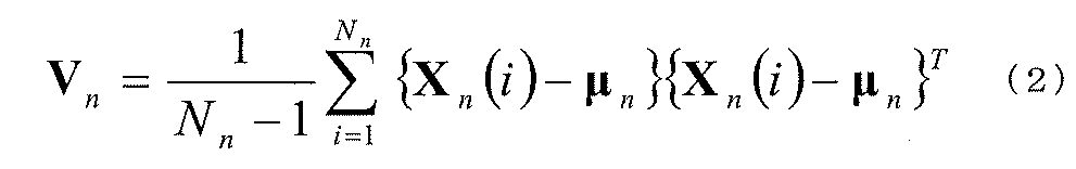
「平均ベクトル」及び「共分散行列」は、対象のボクセル内での点群を正規分布で表現する場合のパラメータに相当する平均ベクトル及び共分散行列を示す。なお、任意のボクセル「n」内の任意の点「i」の座標を
Xn(i)=[xn(i)、yn(i)、zn(i)]T
と定義し、ボクセルn内での点群数を「Nn」とすると、ボクセルnでの平均ベクトル「μn」及び共分散行列「Vn」は、それぞれ以下の式(1)及び式(2)により表される。
The "mean vector" and "covariance matrix" refer to the mean vector and covariance matrix that correspond to the parameters when expressing the point group in the target voxel as a normal distribution. Note that the coordinates of an arbitrary point "i" in an arbitrary voxel "n" are
X n (i) = [x n (i), y n (i), z n (i)] T
and the number of points in voxel n is "N n ", the mean vector "μ n " and the covariance matrix "V n " in voxel n are expressed by the following formulas (1) and (2), respectively.

次に、ボクセルデータVDを用いたNDTスキャンマッチングの概要について説明する。 Next, we will provide an overview of NDT scan matching using voxel data VD.
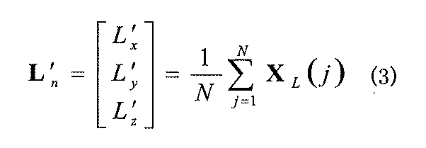
船舶を想定したNDTによるスキャンマッチングは、水平面(ここではxy座標とする)内の移動量及び船舶の向きを要素とした推定パラメータ
P=[tx、ty、tz、tφ、tθ、tψ]T
を推定することとなる。ここで、「tx」はx方向の移動量、「ty」はy方向の移動量、「tz」はz方向の移動量、「tφ」はロール角、「tθ」はピッチ角、「tψ」はヨー角を示す。
The NDT scan matching for ships is based on the estimated parameters, which are the amount of movement in the horizontal plane (here, xy coordinates) and the direction of the ship.
P=[t x , t y , t z , t φ , t θ , t ψ ] T
Here, "t x " represents the amount of movement in the x direction, "t y " represents the amount of movement in the y direction, "t z " represents the amount of movement in the z direction, "t φ " represents the roll angle, "t θ " represents the pitch angle, and "t ψ " represents the yaw angle.
また、ライダ3が出力する点群データの座標を、
XL(j)=[xn(j)、yn(j)、zn(j)]T
とすると、XL(j)の平均値「L´n」は、以下の式(3)により表される。
In addition, the coordinates of the point cloud data output by the
X L (j) = [x n (j), y n (j), z n (j)] T
Then, the average value "L ' n " of X L (j) is expressed by the following formula (3).
そして、自己位置推定部15は、地図DB10と同一の座標系である絶対的な座標系(「ワールド座標系」とも呼ぶ。)に変換した点群データに対応付けられるボクセルデータVDを探索し、そのボクセルデータVDに含まれる平均ベクトルμnと共分散行列Vnとを用い、ボクセルnの評価関数値(「個別評価関数値」とも呼ぶ。)「En」を算出する。この場合、自己位置推定部15は、以下の式(4)に基づき、ボクセルnの個別評価関数値Enを算出する。
Then, the self-
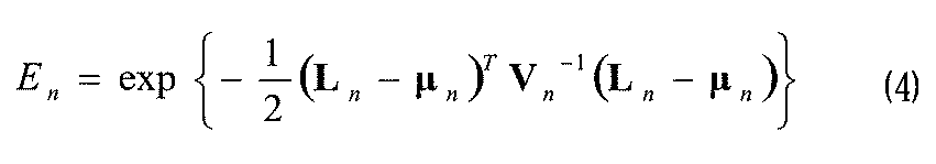
そして、自己位置推定部15は、以下の式(5)により示される、マッチングの対象となる全てのボクセルを対象とした総合的な評価関数値(「スコア値」とも呼ぶ。)「E(k)」を算出する。スコア値Eは、マッチングの適合度を示す指標となる。Then, the self-


(4)障害物/引き波の検出
次に、障害物/引き波検出部16による障害物及び引き波の検出について説明する。障害物/引き波検出部16は、1時刻前までの処理で算出した水面高さを障害物や引き波の検出に使用する。船舶の近くに障害物がある場合、障害物との衝突や接触を避けて航行することが必要となる。障害物とは、例えば、他船、杭、橋脚、ブイ、網、ゴミなどである。また、近くに他船による引き波がある場合、それの影響を受けて揺れが大きくならないように船舶の航行には注意を要する。そこで、障害物/引き波検出部16は、水面高さを用いて、船舶の近くに障害物や引き波があることを検出する。
(4) Obstacle/undertow detection
Next, detection of obstacles and undertow by the obstacle/
(4-1)水面位置の推定
図5は、ライダ3から見た水面高さを説明する図である。船舶は、乗船者数や積荷量に応じて喫水位置が変わる。即ち、ライダ3から見た水面までの高さが変わることになる。図5(A)に示すように、船舶の喫水位置が低い場合、ライダ3から見た水面位置は低めとなる。一方、図5(B)に示すように、船舶の喫水位置が高い場合、ライダ3から見た水面位置は高めとなる。よって、図5(C)に示すように、水面位置を基準として所定の幅を有する探索範囲を設定することにより、障害物や引き波を正しく検出することが可能となる。
(4-1) Estimation of Water Surface Position FIG. 5 is a diagram for explaining the water surface height as seen by the
図6は、ライダ3の出射光の水面反射を説明する図である。下方に向いたライダ3の出射光の一部は、水面で反射してライダ3に戻ってくる場合がある。いま、図6(A)に示すように、船舶上のライダ3がレーザ光を出射しているものとする。図6(B)は、岸壁近くにいる船舶においてライダ3が受光する光を示す。図6(B)において、ビーム101は、水面で反射することなく、直接対象物に照射した光の散乱光の一部がライダ3に戻って受光された光である。ビーム102は、ライダ3から出射され、水面で反射して直接ライダ3に戻って受光された光であり、水面反射光の1つ(以下、「直接水面反射光」とも呼ぶ。)である。ビーム103は、ライダ3から出射され、水面で反射した光が岸壁等に当たり、その錯乱光の一部が再度水面で反射し、それがライダ3に戻って受光された光であり、水面反射光の1つ(以下、「間接水面反射光」とも呼ぶ。)である。ライダ3は水面で反射した光であることを認識できないので、ビーム102を受光した場合、ライダ3はその水面位置に物体があるかのように認識する。また、ビーム103を受光した場合、ライダ3は水面より下方に物体があるかのように認識する。よって、ビーム103を受光したライダは図示のように岸壁内部の位置を示す正しくない点群データを出力することになる。
Figure 6 is a diagram explaining the water surface reflection of light emitted from the
図7は、水面高さ(以下、「水面位置」とも呼ぶ。)の推定に用いる点群データを説明する図である。図7(A)は船舶を後方から見た図であり、図7(B)は船舶を上方から見た図である。船舶の周辺では、水面の揺らぎによって、ライダ3からのビームが水面とほぼ垂直となる場合が時々あり、前述のビーム102のような直接水面反射光が発生する。一方、船舶が岸に近い場合は、ライダ3からのビームが岸などで反射して前述のビーム103のような間接水面反射光が発生する。よって、障害物/引き波検出部16は、船舶の近くにおける直接水面反射光の点群データを複数個取得し、そのz座標値を平均化することにより、水面位置を推定する。船舶は水上に浮いているため、乗船者数や積荷量に応じて水中に沈みこむ量が変わり、ライダ3から水面までの高さが変わる。従って、上記の方法により、常にライダ3から水面までの距離を算出することが可能となる。7 is a diagram explaining the point cloud data used to estimate the water surface height (hereinafter also referred to as the "water surface position"). FIG. 7(A) is a diagram of the ship seen from the rear, and FIG. 7(B) is a diagram of the ship seen from above. Around the ship, the beam from the
具体的に、障害物/引き波検出部16は、ライダ3が出力する点群データから、岸から遠い位置で計測され、かつ、船舶に近い位置で計測された点群データを抽出する。ここで、岸から遠い位置とは、岸から所定距離以上離れた位置をいう。岸の位置は、地図DB10に記憶されている着岸場所(岸、桟橋を含む)などを用いることができる。また、岸とは、着岸場所以外の地上位置や構造物であってもよい。岸から遠い位置で計測された点群データを使用することにより、間接水面反射光の点群データを除外することができる。Specifically, the obstacle/
また、船舶に近い位置とは、船舶の自己位置から所定範囲内の位置をいう。船舶に近い位置で計測された点群データを用いることにより、直接水面反射光を計測した点群データ(以下、「直接水面反射データ」とも呼ぶ。)を使用して、水面位置を高精度に推定することが可能となる。 In addition, a position close to the ship refers to a position within a specified range from the ship's own position. By using point cloud data measured at a position close to the ship, it is possible to estimate the water surface position with high accuracy using point cloud data that measures the light directly reflected from the water surface (hereinafter also referred to as "direct water surface reflection data").
(4-2)障害物の検出
次に、障害物の検出方法を説明する。図8は、障害物の検出方法を説明する図である。上記のようにして水面位置が推定された後、障害物/引き波検出部16は、水面位置付近の高さの点群データに対して、ユークリッドクラスタリング処理を行う。図8(A)に示すように、ユークリッドクラスタリング処理によって、「かたまり」(以下、「クラスタ」とも呼ぶ。)を検出した場合、障害物/引き波検出部16は、そのクラスタを障害物候補として仮判定する。障害物/引き波検出部16は、複数の時刻のフレームで同様にクラスタの検出を行い、各時刻で同様のサイズのクラスタを検出した場合、そのクラスタを何らかの障害物と判定する。
(4-2) Obstacle Detection Next, a method for detecting an obstacle will be described. FIG. 8 is a diagram for explaining the method for detecting an obstacle. After the water surface position is estimated as described above, the obstacle/
なお、ブイなどの水上の小さい障害物などを検出する場合、検出の観点からは水面反射成分も価値ある情報となり得る。図8(B)において、ビーム111は、ライダ3から出射され、ブイで反射してライダ3に戻ったものである。一方、ビーム112は、ライダ3から出射され、水面で反射してブイに当たり、その錯乱光の一部が再度水面で反射し、ライダ3へ戻って受光されたものである。ブイなどの小さい障害物の場合、ビーム111として直接ブイから反射して戻ってくるデータ数は少ないため、ビーム112のように水面で反射した成分のデータも含めることで、解析に用いるデータ数を増やし、クラスタリングに活用する。これにより、クラスタリング処理の対象となるデータ数が増えるため、クラスタリングの性能が向上する。
When detecting small obstacles on the water such as buoys, the water surface reflection component can also be valuable information from the viewpoint of detection. In FIG. 8B,
障害物/引き波検出部16は、検出したクラスタを障害物と判定した場合、その障害物の最も高い位置の点のz座標から、水面位置を減算し、図8(B)に示すように障害物の水面から出ている高さHoを算出する。When the obstacle/
(4-3)引き波の検出方法
次に、引き波の検出方法を説明する。図9は、引き波の検出方法を説明する図である。前述のように水面位置が算出された後、障害物/引き波検出部16は、水面位置付近の高さの点群データに対して、z座標を無視して2次元平面の点群としてハフ変換を行う。図9(A)に示すように、ハフ変換処理によって「直線」を検出した場合、障害物/引き波検出部16は、その直線を引き波候補として仮判定する。障害物/引き波検出部16は、複数の時刻のフレームで同様に直線の検出を行い、各時刻で同様の係数を持つ直線を検出した場合、その直線を引き波と判定する。
(4-3) Method for Detecting Undertow Next, a method for detecting undertow will be described. FIG. 9 is a diagram for explaining a method for detecting undertow. After the water surface position is calculated as described above, the obstacle/
なお、引き波を検出する場合、検出の観点からは水面反射成分も価値ある情報となり得る。図9(B)において、ビーム113は、ライダ3から出射され、引き波で反射してライダ3に戻ったものである。一方、ビーム114は、ライダ3から出射され、水面で反射して引き波に当たり、その錯乱光の一部が再度水面で反射し、ライダ3へ戻って受光されたものである。引き波の場合、ビーム113として直接引き波から反射して戻ってくるデータ数は少ないため、ビーム114のように水面で反射した成分のデータも含めることで、解析に用いるデータ数を増やし、ハフ変換に活用する。これにより、ハフ変換処理の対象となるデータ数が増えるため、ハフ変換の性能が向上する。
When detecting backwash, the water surface reflection component can also be valuable information from the viewpoint of detection. In FIG. 9B,
障害物/引き波検出部16は、上記のように2次元データを用いて引き波の判定を行った後、引き波の一部と判定された点に対して、あらためてz座標を評価する。具体的には、障害物/引き波検出部16は、水面高さよりもz座標値が高い点のみを用いてz座標の平均を求め、その平均値から水面位置を減算して引き波の水面からの高さHwを算出する。After the obstacle/
(4-4)障害物/引き波検出部の実施例
次に、障害物/引き波検出部16の実施例を説明する。以下の実施例では、障害物/引き波検出部16は、引き波検出→障害物検出→水面位置推定の順で処理を行うことにより、後段の処理を行いやすくする。具体的には、水面位置推定ブロック132が推定した水面位置を用いて引き波と障害物の水面からの高さを求めるとともに、次の時刻の点群データに対する探索範囲の設定に使用する。
(4-4) Example of Obstacle/Backwash Detection Unit Next, an example of the obstacle/
図10は、障害物/引き波検出部16の機能構成を示すブロック図である。障害物/引き波検出部16は、ライダ3で計測された点群データを受け取り、引き波情報と障害物情報を出力する。障害物/引き波検出部16は、探索範囲設定ブロック121と、直線抽出ブロック122と、引き波検出ブロック123と、引き波情報算出ブロック124と、引き波データ除去ブロック125と、ユークリッドクラスタリングブロック126と、障害物検出ブロック127と、障害物情報算出ブロック128と、障害物データ除去ブロック129と、平均・分散計算ブロック130と、時間フィルタブロック131と、水面位置推定ブロック132とを備える。
Figure 10 is a block diagram showing the functional configuration of the obstacle/
探索範囲設定ブロック121は、入力された点群データから、直接水面反射光の点群データを抽出し、障害物及び引き波の高さ方向の探索範囲を設定する。障害物/引き波検出部16は、図5(C)に示すように水面位置を中心として設定した探索範囲に属する点群データを抽出し分析することで障害物や引き波を検出するが、船舶の揺れが大きい場合や波が大きい場合、水面に浮遊している障害物や引き波は探索範囲から外れてしまい、検出できなくなる恐れがある。一方、それを回避するために探索範囲を大きくすると、波が小さい場合に無関係なデータが入り込み、検出精度が低下してしまう。The search
そこで、探索範囲設定ブロック121は、前述のように船舶の周辺で得られた直接水面反射データのz座標値の標準偏差を求め、その標準偏差の値を用いて探索範囲を設定する。具体的には、探索範囲設定ブロック121は、直接水面反射データのz座標値の標準偏差を用いて波の高さ(波高)を推定し、波高に応じて探索範囲を設定する。直接水面反射データのz座標値の標準偏差が小さい場合、図11(A)に示すように波高は小さいと推測される。この場合、探索範囲設定ブロック121は探索範囲を狭くする。例えば、探索範囲設定ブロック121は、探索範囲を、直接水面反射データのz座標値の平均値付近に設定する。これにより、ノイズの混入を低減できるため、障害物や引き波の検出精度が向上する。Therefore, the search
一方、直接水面反射のz座標値の標準偏差が大きい場合、図11(B)に示すように波高が大きいと推測される。よって、探索範囲設定ブロック121は探索範囲を広くする。即ち、探索範囲設定ブロック121は、直接水面反射データのz座標値の平均値を中心に、波高が小さいときよりも広い探索範囲を設定する。On the other hand, if the standard deviation of the z-coordinate value of the direct water surface reflection is large, it is estimated that the wave height is large, as shown in Figure 11 (B). Therefore, the search
一例としては、探索範囲設定ブロック121は、図11(C)に示すように、直接水面反射データのz座標値の標準偏差σを用いて、探索範囲を直接水面反射データのz値の平均値を中心として±3σの範囲などと設定してもよい。これにより、波が高い場合でも、探索範囲を広くすることができるため、障害物や引き波の検出漏れを防止することができる。探索範囲設定ブロック121は、設定した探索範囲を直線抽出ブロック122へ出力する。
As an example, as shown in FIG. 11(C), the search
直線抽出ブロック122は、船舶周辺の探索範囲内で計測された直接水面反射データ(以下、「探索データ」とも呼ぶ。)から、ハフ変換を用いて直線を抽出する。直線抽出ブロック122は、抽出した直線を引き波検出ブロック123へ出力する。ハフ変換で直線を検出する際には離散化した2次元配列を用いるため、結果として求まる直線は近似的なものとなる。従って、直線抽出ブロック122と引き波検出ブロック123では、以下の手順により、より正確な直線を求める。
(手順1)ハフ変換で近似直線を算出する。
(手順2)近似直線への距離が所定の閾値(直線距離閾値)以内であるデータを抽出する。
(手順3)抽出した複数のデータを用いて主成分分析を行い、直線をあらためて算出し、引き波の直線とする。
The
(Step 1) Calculate an approximate straight line using the Hough transform.
(Step 2) Extract data whose distance to the approximation line is within a predetermined threshold (straight-line distance threshold).
(Step 3) Principal component analysis is performed using the multiple extracted data, and a straight line is recalculated to represent the backwash line.
上記の手順で直線を検出するシミュレーションを行った結果を図12に示す。図示のように、ハフ変換により求めた直線141は近似直線のため、データに対して少しずれがあることがわかる。直線141から直線距離閾値以内のデータを抽出し(図12では□でマーキング)、抽出されたデータを用いて主成分分析であらためて直線を算出することで、正確な引き波直線142を得ることができる。Figure 12 shows the results of a simulation performed to detect a straight line using the above procedure. As shown, the
引き波検出ブロック123は、あらためて算出した直線を引き波と判定し、引き波を示す引き波データを引き波情報算出ブロック124及び引き波データ除去ブロック125へ出力する。引き波情報算出ブロック124は、引き波を示す直線の式と、船舶の自己位置とに基づいて引き波の位置、距離、角度、及び、高さを算出し、引き波情報として出力する。The
引き波データ除去ブロック125は、船舶周辺の探索範囲内で計測された探索データから引き波データを除去し、ユークリッドクラスタリングブロック126へ出力する。ユークリッドクラスタリングブロック126は、入力された探索データに対してユークリッドクラスタリング処理を行い、探索データのクラスタを検出して障害物検出ブロック127へ出力する。The backwash
ユークリッドクラスタリングでは、まず対象となる全ての点に対し、他の全ての点との間の距離を計算し、得られた点間距離が所定値(以下、「グルーピング閾値」と呼ぶ。)よりも短い点を同じグループに入れる。次に、各グループのうち、所定の点数(以下、「点数閾値」と呼ぶ。)以上の点を含むグループをクラスタと見なす。なお、点数が少ないグループはノイズである可能性が高いため、クラスタとは見なさない。In Euclidean clustering, the distance between every target point and every other point is first calculated, and points whose inter-point distance is shorter than a predetermined value (hereafter referred to as the "grouping threshold") are placed in the same group. Next, of each group, groups that contain points with a predetermined score or more (hereafter referred to as the "score threshold") are considered to be clusters. Note that groups with low scores are not considered to be clusters, as they are likely to be noise.
図13は、ユークリッドクラスタリングの例を示す。図13(A)は、ユークリッドクラスタリングの対象となる複数の点を示す。図13(A)に示す各点の点間距離を計算し、グルーピング閾値と比較することによりグルーピングを行った。図13(B)の各矢印が示す距離がグルーピング閾値より大きいので、図13(B)に破線で示す5つのグループA~Eが得られた。次に、各グループに属する点数を点数閾値(ここでは「6」とする。)と比較し、図13(C)に示すように、点数閾値よりも多数の点を含むグループAとCのみが最終的にクラスタと判定された。 Figure 13 shows an example of Euclidean clustering. Figure 13(A) shows multiple points that are the subject of Euclidean clustering. Grouping was performed by calculating the inter-point distance between each point shown in Figure 13(A) and comparing it with a grouping threshold. Since the distances indicated by the arrows in Figure 13(B) are greater than the grouping threshold, five groups A to E shown by dashed lines in Figure 13(B) were obtained. Next, the scores belonging to each group were compared with the score threshold (set to "6" here), and only groups A and C, which contain more points than the score threshold, were ultimately determined to be clusters, as shown in Figure 13(C).
図14は、ユークリッドクラスタリングのシミュレーション結果を示す。図14(A)は、ユークリッドクラスタリングの際に引き波データが残っている場合のシミュレーション結果を示す。ユークリッドクラスタリングにおいて、グルーピング閾値でグループ判別を行う際、引き波データが残っていると、障害物と引き波を一緒のクラスタと判定してしまう恐れがある。図14(A)の例では、引き波と障害物が近かったために障害物と引き波のデータが同じグループとなり、そのグループの点数が点数閾値よりも高かったため、同じクラスタとして検出されてしまっている。 Figure 14 shows the simulation results of Euclidean clustering. Figure 14 (A) shows the simulation results when backwash data remains during Euclidean clustering. In Euclidean clustering, when performing group discrimination using a grouping threshold, if backwash data remains, there is a risk that the obstacle and backwash will be determined to be in the same cluster. In the example of Figure 14 (A), the backwash and the obstacle are close to each other, so the obstacle and backwash data are in the same group, and because the score of that group is higher than the score threshold, they are detected as being in the same cluster.
図14(B)は、引き波データを除去した後でユークリッドクラスタリングを行った場合のシミュレーション結果を示す。障害物を引き波と区別するため、引き波検出を先に行い、引き波データと判定されたデータを除いた上で、ユークリッドクラスタリングを行っている。この場合、引き波データの影響を受けることなく、障害物が正しくクラスタとして検出されている。 Figure 14 (B) shows the simulation results when Euclidean clustering was performed after removing the backwash data. To distinguish obstacles from backwash, backwash detection was performed first, and data determined to be backwash data was removed before Euclidean clustering was performed. In this case, obstacles were correctly detected as clusters without being affected by the backwash data.
一般的に、ライダの光ビームは放射状に出力されるため、データは遠くなるほど位置の間隔が広がる。よって、図15に示すように、距離の遠いデータほど、隣接するデータとの間隔が離れることになる。また、同じ大きさの物体であっても、近くに存在する場合は検出点数が多くなり、遠くに存在する場合は検出点数が少なくなる。従って、ユークリッドクラスタリング処理において、データの距離値に応じてグルーピング閾値と点数閾値を設定することで、ライダから近い物体でも遠い物体でもできるだけ同様の条件でクラスタリング判定を行うことができる。 In general, because the light beam of a lidar is output radially, the farther away the data is, the greater the distance between the positions. Therefore, as shown in FIG. 15, the farther away the data is, the greater the distance between adjacent data. Also, even for objects of the same size, the number of detection points will be greater if they are close, and fewer if they are far away. Therefore, in Euclidean clustering processing, by setting a grouping threshold and a score threshold according to the distance value of the data, it is possible to perform clustering determination under as similar conditions as possible for objects close to and far from the lidar.
図16は、データの距離が遠いほどグルーピング閾値を大きくし、グループの重心点までの距離が遠いほど点数閾値を小さくしてシミュレーションを行った結果を示す。 Figure 16 shows the results of a simulation in which the grouping threshold was increased as the distance of the data increased, and the score threshold was decreased as the distance to the center of gravity of the group increased.
図16(A)は、
グルーピング閾値=2.0m
点数閾値=6点
とした場合のシミュレーション結果を示す。
FIG. 16A is a diagram showing a
Grouping threshold = 2.0 m
The simulation results when the score threshold is set to 6 points are shown.
図16(B)は、
グルーピング閾値=a×(データ距離)、
点数閾値=b/(グループの重心点までの距離)
としたときのシミュレーション結果を示す。なお、このシミュレーションでは、a=0.2、b=80としたが、実際にはライダ3の特性により好適な値に設定される。
FIG. 16B is a diagram showing
Grouping threshold=a×(data distance),
Score threshold = b / (distance to center of gravity of group)
In this simulation, a=0.2 and b=80, but in practice, these are set to values suitable for the characteristics of the
図16(A)と図16(B)を比較するとわかるように、図16(B)では、船舶の近くに位置するクラスタ1に加えて、船舶の遠くに位置するクラスタ2も検出できている。クラスタ2は、各データ間の距離は3m近辺の値であるが、船舶からデータまでの距離を用いて算出されたグルーピング閾値は約4.5mであるため、その閾値よりも距離が近いため同じグループとなり、またデータ点数は4点であるが、グループの重心点までの距離を用いて算出された点数閾値は約3.2であるため、その閾値よりも点数が多かったため,クラスタと判定された。なお、上記の式を用いると、クラスタ1は、船舶からデータまでの距離を用いて算出されたグルーピング閾値は2.5m近辺の値であり、点数閾値は約7.1となるため、図16(A)の固定値と比べて大きく変わっていないことがわかる。このように適応的な閾値設定により、クラスタの未検出と誤検出を極力防止することができ、障害物検出の性能を向上させることができる。
As can be seen by comparing FIG. 16(A) and FIG. 16(B), in addition to
障害物検出ブロック127は、ユークリッドクラスタリングにより検出された障害物を示す点群データ(以下、「障害物データ」呼ぶ。)を、障害物情報算出ブロック128及び障害物データ除去ブロック129へ出力する。障害物情報算出ブロック128は、障害物データに基づき、船舶の自己位置を基準とした障害物の位置、距離、角度、サイズ及び高さを算出し、障害物情報として出力する。The
障害物データ除去ブロック129は、船舶周辺の探索範囲内で計測された探索データから障害物データを除去し、平均・分散計算ブロック130へ出力する。船舶周辺の直接水面反射データから水面位置を推定する際、引き波や障害物が存在すると、正しく水面位置を推定することができないためである。The obstacle
図17(A)は、船舶の周辺に引き波や障害物がある場合に得られた直接水面反射データを示す。この場合、水面よりも高い位置のデータや、障害物や引き波による間接水面反射光(図8(B)のビーム112、図9(B)のビーム114など)は、水面位置推定における誤差要因となる。よって、引き波データ除去ブロック125及び障害物データ除去ブロック129により、図17(B)に示すように引き波や障害物を除去した後の探索データを用いて水面位置推定が行われる。具体的には、図18に示すように、船舶の周辺に引き波と障害物がある状態1から、状態2に示すように引き波を検出して除去し、状態3とする。次に、状態4に示すように障害物を検出して除去し、状態5に示すように、引き波や障害物を含まない直接水面反射データを得る。
Figure 17 (A) shows direct water surface reflection data obtained when there is a wake or obstacle around the ship. In this case, data above the water surface and indirect water surface reflection light due to obstacles or wake (such as
具体的に、平均・分散計算ブロック130は、船舶周辺で得られた直接水面反射データのz座標値の平均値及び分散値を算出し、時間フィルタブロック131へ出力する。時間フィルタブロック131は、入力された直接水面反射データのz座標値の平均値を、過去の水面位置と平均化処理又はフィルタリング処理する。水面位置推定ブロック132は、平均化処理又はフィルタリング処理後のz座標値の平均値と、探索データのz座標値の分散値とを用いて、水面位置を推定する。Specifically, the average/
水面位置を推定する際、船舶周辺の直接水面反射データの分散値が大きい場合、他船の通過などによって波が高くなっている、あるいは障害物として検出されなかった浮遊物等が存在すると予想することができる。よって、分散値が所定値より小さい場合、水面位置推定ブロック132は、直接水面反射データの平均値を用いて水面位置を推定、更新する。一方、分散値が所定値以上である場合、水面位置推定ブロック132は、水面位置を更新せず、前回の値を維持する。ここで、「所定値」は、固定値でもよく、過去の分散値の平均値を基に設定した値、例えば分散値の平均値の2倍などとしてもよい。そして、水面位置推定ブロック132は、推定した水面位置を探索範囲設定ブロック121、引き波情報算出ブロック124及び障害物情報算出ブロック128へ出力する。こうして、新たに得られた直接水面反射データに基づいて水面位置を更新しつつ、引き波及び障害物が検出される。When estimating the water surface position, if the variance value of the direct water surface reflection data around the ship is large, it can be expected that the waves are high due to the passage of other ships, or that there are floating objects that were not detected as obstacles. Therefore, if the variance value is smaller than a predetermined value, the water surface position estimation block 132 estimates and updates the water surface position using the average value of the direct water surface reflection data. On the other hand, if the variance value is equal to or greater than the predetermined value, the water surface
(4-5)障害物/引き波検出処理
次に、障害物/引き波検出部16により実行される障害物/引き波検出処理について説明する。図19は、障害物/引き波検出処理のフローチャートである。この処理は、図2に示すコントローラが予め用意されたプログラムを実行し、図10に示す各要素として動作することにより実現される。
(4-5) Obstacle/wake detection processing Next, the obstacle/wake detection processing executed by the obstacle/
まず、障害物/引き波検出部16は、ライダ3により計測された点群データを取得する(ステップS11)。次に、探索範囲設定ブロック121は、1時刻前までの推定水面位置と、船舶の周辺で得られた直接水面反射データのz座標値の標準偏差σとから、探索範囲を決定する(ステップS12)。例えば、探索範囲設定ブロック121は、標準偏差σのとき、
探索範囲=推定水面位置±3σ
とする。
そして、探索範囲設定ブロック121は、決定した探索範囲内の点群データを抽出して、引き波検出用の探索データとする(ステップS13)。
First, the obstacle/
Search range = Estimated water surface position ±3σ
Let us assume that.
Then, the search
次に、障害物/引き波検出部16は、引き波検出処理を実行する(ステップS14)。図20は、引き波検出処理のフローチャートである。まず、直線抽出ブロック122は、探索範囲から得られた探索データの各点に対し、一旦z値を無視してxとyの2次元のデータとする(ステップS101)。次に、直線抽出ブロック122は、全ての探索点に対し、以下の式(7)を用いてθを0~180度の範囲で変化させて、(θ,ρ)を算出する(ステップS102)。(θ,ρ)を要素とする離散化した2次元配列を作成するため、「θ」と「ρ」は整数で表現する。Next, the obstacle/

次に、直線抽出ブロック122は、各(θ,ρ)の個数を調べて、所定値よりも大きく極大値となるものを抽出する(ステップS103)。(θ,ρ)をn個抽出した場合、(θ1,ρ1)~(θn,ρn)が得られる。次に、直線抽出ブロック122は、抽出した(θ1,ρ1)~(θn,ρn)を式(7)に代入し、n本の直線L1~Lnを生成する(ステップS104)。
Next, the
次に、引き波検出ブロック123は、あらためて、全ての探索点に対して、生成したn本の直線L1~Lnまでの距離を算出し、所定の距離以下となるものを引き波データとする(ステップS105)。次に、引き波検出ブロック123は、上記の引き波データについて、z値も含めた3次元のデータを引き波データとする(ステップS106)。次に、引き波検出ブロック123は、抽出した引き波データを用いて、最小二乗法あるいは主成分分析にて、n本の直線の式をあらためて算出する(ステップS107)。そして、処理は図19のメインルーチンへ戻る。
Next, the
次に、引き波データ除去ブロック125は、探索データから引き波データを除去して、障害物検出用の探索データとする(ステップS15)。Next, the backwash
次に、障害物/引き波検出部16は、障害物検出処理を実行する(ステップS16)。図22は、障害物検出処理のフローチャートである。まず、ユークリッドクラスタリングブロック126は、全ての探索データに対し、他の全ての探索データとの間の点間距離を算出する(ステップS111)。もし探索データがn個の場合は、n(n-1)個の点間距離が算出されることになる。次に、ユークリッドクラスタリングブロック126は、最初の対象データを選択し(ステップS112)、船舶から対象データまでの距離r1を算出し、所定の係数aを用いてグルーピング閾値T1を算出する(ステップS113)。例えば、T1=a・r1とする。すなわち、グルーピング閾値T1は対象データごとに異なる値となる。Next, the obstacle/
次に、ユークリッドクラスタリングブロック126は、対象データとの点間距離が、グルーピング閾値T1より小さいデータを同じグループとする(ステップS114)。次に、ユークリッドクラスタリングブロック126は、全ての探索データを対象にしたか否かを判定する(ステップS115)。全ての探索データを対象にしていない場合(ステップS115:No)、ユークリッドクラスタリングブロック126は、次の対象データを選択し(ステップS116)、ステップS113へ戻る。Next, the
一方、全ての探索データを対象とした場合(ステップS115:Yes)、ユークリッドクラスタリングブロック126は、抽出したグループに対してそれぞれ重心位置を求め、その重心位置までの距離r2を算出する。そして、所定の係数bを用いて、点数閾値T2を設定する(ステップS117)。例えば、T2=b/r2とする。すなわち、点数閾値T2はグループごとに異なる値となる。On the other hand, if all search data is targeted (step S115: Yes), the
次に、ユークリッドクラスタリングブロック126は、グループごとに、点数閾値T2以上のデータ数が含まれるものをクラスタと判定し、障害物検出ブロック127は、そのクラスタを障害物とする(ステップS118)。そして、処理は図19のメインルーチンへ戻る。Next, the
次に、障害物データ除去ブロック129は、探索データから障害物と判定されたデータを除去して、水面位置推定のためのデータとする(ステップS17)。Next, the obstacle
次に、障害物/引き波検出部16は、水面位置推定処理を実行する(ステップS18)。図23は、水面位置推定処理のフローチャートである。まず、平均・分散計算ブロック130は、岸から遠く、船舶位置に近く、水面位置付近に存在するデータを水面反射データと判定する(ステップS121)。次に、平均・分散計算ブロック130は、複数スキャンフレームの水面反射データを求め、所定のデータ数に達したら、それらのz方向の平均値と分散値を求める(ステップS122)。Next, the obstacle/
次に、平均・分散計算ブロック130は、分散値が所定値未満であるか否かを判定する(ステップS123)。分散値が所定値未満でない場合(ステップS123:No)、処理はステップS125へ進む。一方、分散値が所定値未満である場合(ステップS123:Yes)、時間フィルタブロック131は、求めたz値の平均値と、過去の推定水面位置とのフィルタリング処理を行い、水面位置を更新する(ステップS124)。次に、水面位置推定ブロック132は、算出した水面位置と分散値を出力する(ステップS125)。そして、処理は図19のメインルーチンへ戻る。Next, the average/
次に、障害物/引き波検出部16は、引き波情報算出処理を実行する(ステップS19)。図24(A)は、引き波情報算出処理のフローチャートである。まず、引き波情報算出ブロック124は、船舶の自己位置を基準とし、引き波検出ブロック123が検出した直線までの最短距離を計算し、引き波までの距離とする。また、その距離となる位置を求め、引き波の位置とする。また、その直線の係数から傾きを算出し、引き波の角度とする(ステップS131)。Next, the obstacle/
なお、図24(B)に示すように、船舶の自己位置から直線までの最短距離は、直線に下した垂線の足までの距離となる。しかし、引き波として検出された直線は線分であるため、図24(C)に示すように、引き波として検出されたデータの端点が最短距離となる場合もある。従って、引き波情報算出ブロック124は、垂線の足までの座標が線分内にあるかどうかを確認し、ない場合は線分の端点までの距離を最短距離とする。As shown in Figure 24 (B), the shortest distance from the ship's own position to a straight line is the distance to the foot of a perpendicular line dropped to the straight line. However, because the straight line detected as a backwash is a line segment, the end point of the data detected as a backwash may be the shortest distance, as shown in Figure 24 (C). Therefore, the backwash
次に、引き波情報算出ブロック124は、推定した水面位置よりもz値が高い点のみを用いてz座標値の平均を求め、推定した水面位置を用いて、引き波の水面からの高さを算出する(ステップS132)。なお、z座標値の平均値の代わりに、最大値を用いて引き波の高さとしてもよい。そして、処理は図19のメインルーチンへ戻る。Next, the backwash
次に、障害物/引き波検出部16は、障害物情報算出処理を実行する(ステップS20)。図25は、障害物情報算出処理のフローチャートである。まず、障害物情報算出ブロック128は、船舶の自己位置を基準とし、障害物として検出されたクラスタデータの中で最短距離となるものを抽出し、それを障害物の位置とする。また、そのデータまでの距離を求め、障害物までの距離とする。さらに、そのデータの座標から障害物の角度を求める(ステップS141)。Next, the obstacle/
次に、障害物情報算出ブロック128は、クラスタデータの中で、xとyの2次元平面において最も距離の離れている2点を抽出し、その距離を障害物の横方向のサイズとする。また、クラスタデータの中で、最も高い位置の点のz座標から推定した水面位置を減算し、障害物の水面からの高さとする(ステップS142)。そして、処理は図19のメインルーチンへ戻る。Next, the obstacle
次に、障害物/引き波検出部16は、複数のフレームで同様の引き波を検出したか否かを判定する(ステップS21)。船舶自体や引き波が移動する場合は厳密に一致することはないものの、ステップS19で算出する値が少しの違いしかなければ、同様の引き波と判定する。同様の引き波を検出しない場合(ステップS21:No)、処理はステップS23へ進む。一方、同様の引き波を検出した場合(ステップS21:Yes)、引き波情報算出ブロック124は、そのデータを引き波と断定し、引き波情報を船体システムに出力する(ステップS22)。Next, the obstacle/
次に、障害物/引き波検出部16は、複数のフレームで同様の障害物を検出したか否かを判定する(ステップS23)。船舶自体や障害物が移動する場合は厳密に一致することはないものの、ステップS20で算出する値が少しの違いしかなければ、同様の障害物と判定する。同様の障害物を検出しない場合(ステップS23:No)、処理は終了する。一方、同様の障害物を検出した場合(ステップS23:Yes)、障害物情報算出ブロック128は、そのデータを障害物と断定し、障害物情報を船体システムに出力する(ステップS24)。そして、処理は終了する。Next, the obstacle/
(4-6)変形例
(変形例1)
上記の水面位置推定では水面反射データの分散値を利用しているが、図26に例示するように、積み荷の偏り等で船体がロール方向に静的に傾いていると、水面反射データの分散値も大きくなってしまう。このような状況で水面位置を推定する際には、水面位置推定ブロック132は、右舷側の水面反射データと、左舷側の水面反射データをそれぞれ別々に処理し、右舷側の水面位置と左舷側の水面位置とを別々に求めてもよい。もしくは、水面位置推定ブロック132は、水面反射データの右舷側の平均値と左舷側の平均値との差分が小さくなるように、ロール角を回転させる座標変換を水面反射データに対して施すことにより、右舷と左舷とを分けずに水面位置を推定できるようになる。
(4-6) Modification (Modification 1)
The above water surface position estimation uses the variance value of the water surface reflection data, but as shown in Fig. 26, if the hull is statically tilted in the roll direction due to uneven loading or the like, the variance value of the water surface reflection data also becomes large. When estimating the water surface position in such a situation, the water surface
(変形例2)
上記の実施例では、直線抽出ブロック122は以下の手順1~手順3により引き波の直線を抽出している。
(手順1)ハフ変換で近似直線を算出する。
(手順2)近似直線への距離が所定の閾値(直線距離閾値)以内であるデータを抽出する。
(手順3)抽出した複数のデータを用いて主成分分析を行い、直線をあらためて算出し、引き波の直線とする。
(Variation 2)
In the above embodiment, the straight
(Step 1) Calculate an approximate straight line using the Hough transform.
(Step 2) Extract data whose distance to the approximation line is within a predetermined threshold (straight-line distance threshold).
(Step 3) Principal component analysis is performed using the multiple extracted data, and a straight line is recalculated to represent the backwash line.
これに対し、以下の手順4を追加し、手順4の判定によって手順2と手順3を繰り返し実行してもよい。
(手順4)抽出されるデータが変わり、直線の式が変化した場合は、手順2に戻る。直線の式が変化しなくなったら、それを引き波の直線とする。
Alternatively, the following
(Step 4) If the extracted data changes and the equation of the line changes, return to
図27の左側のグラフは、上記の手順4を実施せずに直線を求めた場合の例を示し、右側のグラフは手順4まで実施して、直線生成を収束させた場合の例を示す。手順4を加えることにより、引き波データの抽出漏れがなくなり、結果として直線の精度を向上させることができる。
The graph on the left side of Figure 27 shows an example of finding a straight line without performing
以上、実施例を参照して本願発明を説明したが、本願発明は上記実施例に限定されるものではない。本願発明の構成や詳細には、本願発明のスコープ内で当業者が理解し得る様々な変更をすることができる。すなわち、本願発明は、請求の範囲を含む全開示、技術的思想にしたがって当業者であればなし得るであろう各種変形、修正を含むことは勿論である。また、引用した上記の特許文献等の各開示は、本書に引用をもって繰り込むものとする。 Although the present invention has been described above with reference to examples, the present invention is not limited to the above examples. Various modifications that a person skilled in the art can make within the scope of the present invention may be made to the configuration and details of the present invention. In other words, the present invention naturally includes various modifications and amendments that a person skilled in the art could make in accordance with the entire disclosure, including the scope of the claims, and the technical ideas. Furthermore, the disclosures of the above cited patent documents, etc. are incorporated herein by reference.
1 情報処理装置
2 センサ群
3 ライダ
4 速度センサ
5 GPS受信機
6 IMU
10 地図DB
13 コントローラ
15 自己位置推定部
16 障害物/引き波検出部
121 探索範囲設定ブロック
122 直線抽出ブロック
123 引き波検出ブロック
124 引き波情報算出ブロック
125 引き波データ除去ブロック
126 ユークリッドクラスタリングブロック
127 障害物検出ブロック
128 障害物情報算出ブロック
129 障害物データ除去ブロック
130 平均・分散計算ブロック
131 時間フィルタブロック
132 水面位置推定ブロック
10 Map DB
13
Claims (12)
前記点群データに基づいて、前記船舶の自己位置を推定する自己位置推定手段と、
岸の位置を取得する岸位置取得手段と、
前記船舶の自己位置及び前記岸の位置に基づいて、前記岸から第1の所定距離離れており、かつ、前記船舶の自己位置から第2の所定距離以内の位置の点群データを、水面において反射されることで計測された水面反射データとして抽出する水面反射データ抽出手段と、
前記水面反射データに基づき、水面高さを算出する水面高さ算出手段と、
を有する情報処理装置。 A point cloud data acquisition means for acquiring point cloud data generated by a measuring device installed on the ship;
a vessel position estimation means for estimating a vessel position based on the point cloud data;
A shore position acquisition means for acquiring the position of a shore;
a water surface reflection data extraction means for extracting point cloud data of a position that is a first predetermined distance away from the shore and within a second predetermined distance from the ship's own position based on the ship's own position and the position of the shore as water surface reflection data measured by reflection on the water surface;
A water surface height calculation means for calculating a water surface height based on the water surface reflection data;
An information processing device having the above configuration.
前記探索範囲に属する水面反射データに基づいて引き波を検出する引き波検出手段と、A backwash detection means for detecting backwash based on the water surface reflection data belonging to the search range;
前記探索範囲に属する水面反射データから前記引き波に対応するデータを除去した引き波除去データに基づいて、障害物を検出する障害物検出手段と、an obstacle detection means for detecting an obstacle based on backwash removed data obtained by removing data corresponding to the backwash from the water surface reflection data belonging to the search range;
を備え、Equipped with
前記水面高さ算出手段は、前記引き波除去データから前記障害物に対応するデータを除去した障害物除去データに基づいて、前記水面高さを算出する請求項1に記載の情報処理装置。2. The information processing apparatus according to claim 1, wherein the water surface height calculation means calculates the water surface height based on obstacle-removed data obtained by removing data corresponding to the obstacles from the undertow-removed data.
船舶に設けられた計測装置が生成する点群データを取得し、
前記点群データに基づいて、前記船舶の自己位置を推定し、
岸の位置を取得し、
前記船舶の自己位置及び前記岸の位置に基づいて、前記岸から第1の所定距離離れており、かつ、前記船舶の自己位置から第2の所定距離以内の位置の点群データを、水面において反射されることで計測された水面反射データとして抽出し、
前記水面反射データに基づき、水面高さを算出する制御方法。 A computer-implemented control method, comprising:
Acquire point cloud data generated by measuring devices installed on the ship,
Estimating a self-position of the vessel based on the point cloud data;
Get the location of the shore,
extracting point cloud data of a position that is a first predetermined distance away from the shore and within a second predetermined distance from the ship's own position based on the ship's own position and the position of the shore as water surface reflection data measured by reflection on the water surface;
A control method for calculating a water surface height based on the water surface reflection data.
前記点群データに基づいて、前記船舶の自己位置を推定し、
岸の位置を取得し、
前記船舶の自己位置及び前記岸の位置に基づいて、前記岸から第1の所定距離離れており、かつ、前記船舶の自己位置から第2の所定距離以内の位置の点群データを、水面において反射されることで計測された水面反射データとして抽出し、
前記水面反射データに基づき、水面高さを算出する処理をコンピュータに実行させるプログラム。 Acquire point cloud data generated by measuring devices installed on the ship,
Estimating a self-position of the vessel based on the point cloud data;
Get the location of the shore,
extracting point cloud data of a position that is a first predetermined distance away from the shore and within a second predetermined distance from the ship's own position based on the ship's own position and the position of the shore as water surface reflection data measured by reflection on the water surface;
A program that causes a computer to execute a process of calculating the water surface height based on the water surface reflection data.
Priority Applications (2)
| Application Number | Priority Date | Filing Date | Title |
|---|---|---|---|
| JP2024134980A JP2024155952A (en) | 2021-03-15 | 2024-08-13 | Information processing device, information processing method, program, and storage medium |
| JP2025280269A JP2026042812A (en) | 2021-03-15 | 2025-12-24 | Information processing device, information processing method, program, and storage medium |
Applications Claiming Priority (1)
| Application Number | Priority Date | Filing Date | Title |
|---|---|---|---|
| PCT/JP2021/010365 WO2022195670A1 (en) | 2021-03-15 | 2021-03-15 | Information processing apparatus, control method, program, and storage medium |
Related Child Applications (1)
| Application Number | Title | Priority Date | Filing Date |
|---|---|---|---|
| JP2024134980A Division JP2024155952A (en) | 2021-03-15 | 2024-08-13 | Information processing device, information processing method, program, and storage medium |
Publications (2)
| Publication Number | Publication Date |
|---|---|
| JPWO2022195670A1 JPWO2022195670A1 (en) | 2022-09-22 |
| JP7539552B2 true JP7539552B2 (en) | 2024-08-23 |
Family
ID=83320012
Family Applications (3)
| Application Number | Title | Priority Date | Filing Date |
|---|---|---|---|
| JP2023506395A Active JP7539552B2 (en) | 2021-03-15 | 2021-03-15 | Information processing device, control method, program, and storage medium |
| JP2024134980A Pending JP2024155952A (en) | 2021-03-15 | 2024-08-13 | Information processing device, information processing method, program, and storage medium |
| JP2025280269A Pending JP2026042812A (en) | 2021-03-15 | 2025-12-24 | Information processing device, information processing method, program, and storage medium |
Family Applications After (2)
| Application Number | Title | Priority Date | Filing Date |
|---|---|---|---|
| JP2024134980A Pending JP2024155952A (en) | 2021-03-15 | 2024-08-13 | Information processing device, information processing method, program, and storage medium |
| JP2025280269A Pending JP2026042812A (en) | 2021-03-15 | 2025-12-24 | Information processing device, information processing method, program, and storage medium |
Country Status (4)
| Country | Link |
|---|---|
| US (1) | US20240175984A1 (en) |
| EP (1) | EP4310550A4 (en) |
| JP (3) | JP7539552B2 (en) |
| WO (1) | WO2022195670A1 (en) |
Families Citing this family (5)
| Publication number | Priority date | Publication date | Assignee | Title |
|---|---|---|---|---|
| US11364328B2 (en) | 2018-02-28 | 2022-06-21 | Nxstage Medical, Inc. | Fluid preparation and treatment devices methods and systems |
| EP4186848B1 (en) * | 2021-11-30 | 2024-05-15 | B&R Industrial Automation GmbH | Trajectory planning with flexible obstacle planning functionality |
| WO2024189755A1 (en) * | 2023-03-14 | 2024-09-19 | 三菱電機株式会社 | Estimation device, estimation system and estimation method |
| CN119429016B (en) * | 2024-11-29 | 2025-11-14 | 沪东中华造船(集团)有限公司 | A method for installing large-diameter segmented outer pipes |
| CN119763055B (en) * | 2024-12-19 | 2025-07-18 | 芜湖太航信息技术有限公司 | A ship load prediction system based on image recognition |
Citations (9)
| Publication number | Priority date | Publication date | Assignee | Title |
|---|---|---|---|---|
| JP2006292429A (en) | 2005-04-06 | 2006-10-26 | Mitsubishi Electric Corp | Target detection device |
| JP2008281380A (en) | 2007-05-09 | 2008-11-20 | Ihi Corp | Data correction device and method of three-dimensional sensor |
| JP2011530712A (en) | 2008-08-12 | 2011-12-22 | ジェイケイ ヴィジョン アーエス | A system for detecting and imaging objects on the ship's route. |
| JP2012237592A (en) | 2011-05-10 | 2012-12-06 | Ihi Corp | Laser radar device and laser radar method |
| WO2014192530A1 (en) | 2013-05-31 | 2014-12-04 | 古野電気株式会社 | Stern-wave detection device, radar device, stern-wave detection method, and stern-wave detection program |
| JP2016206152A (en) | 2015-04-28 | 2016-12-08 | 古野電気株式会社 | Wave radar device |
| JP2017133902A (en) | 2016-01-27 | 2017-08-03 | 国立大学法人 千葉大学 | Wave measurement device and target detection device |
| WO2017204076A1 (en) | 2016-05-26 | 2017-11-30 | 古野電気株式会社 | Signal processing device and radar device |
| CN109917414A (en) | 2019-03-20 | 2019-06-21 | 北京视酷伟业科技股份有限公司 | A kind of ship freeboard measurement method and system based on laser technology |
Family Cites Families (5)
| Publication number | Priority date | Publication date | Assignee | Title |
|---|---|---|---|---|
| WO2013076829A1 (en) | 2011-11-22 | 2013-05-30 | 株式会社日立製作所 | Autonomous mobile system |
| WO2018221453A1 (en) | 2017-05-31 | 2018-12-06 | パイオニア株式会社 | Output device, control method, program, and storage medium |
| JP7083081B2 (en) | 2018-10-10 | 2022-06-10 | ヤンマーパワーテクノロジー株式会社 | Automatic berthing device |
| WO2021084583A1 (en) * | 2019-10-28 | 2021-05-06 | 三菱電機株式会社 | Obstacle detection device, obstacle detection method, and obstacle detection program |
| CN111239766B (en) * | 2019-12-27 | 2021-12-07 | 北京航天控制仪器研究所 | Water surface multi-target rapid identification and tracking method based on laser radar |
-
2021
- 2021-03-15 US US18/282,120 patent/US20240175984A1/en active Pending
- 2021-03-15 JP JP2023506395A patent/JP7539552B2/en active Active
- 2021-03-15 EP EP21931426.7A patent/EP4310550A4/en active Pending
- 2021-03-15 WO PCT/JP2021/010365 patent/WO2022195670A1/en not_active Ceased
-
2024
- 2024-08-13 JP JP2024134980A patent/JP2024155952A/en active Pending
-
2025
- 2025-12-24 JP JP2025280269A patent/JP2026042812A/en active Pending
Patent Citations (9)
| Publication number | Priority date | Publication date | Assignee | Title |
|---|---|---|---|---|
| JP2006292429A (en) | 2005-04-06 | 2006-10-26 | Mitsubishi Electric Corp | Target detection device |
| JP2008281380A (en) | 2007-05-09 | 2008-11-20 | Ihi Corp | Data correction device and method of three-dimensional sensor |
| JP2011530712A (en) | 2008-08-12 | 2011-12-22 | ジェイケイ ヴィジョン アーエス | A system for detecting and imaging objects on the ship's route. |
| JP2012237592A (en) | 2011-05-10 | 2012-12-06 | Ihi Corp | Laser radar device and laser radar method |
| WO2014192530A1 (en) | 2013-05-31 | 2014-12-04 | 古野電気株式会社 | Stern-wave detection device, radar device, stern-wave detection method, and stern-wave detection program |
| JP2016206152A (en) | 2015-04-28 | 2016-12-08 | 古野電気株式会社 | Wave radar device |
| JP2017133902A (en) | 2016-01-27 | 2017-08-03 | 国立大学法人 千葉大学 | Wave measurement device and target detection device |
| WO2017204076A1 (en) | 2016-05-26 | 2017-11-30 | 古野電気株式会社 | Signal processing device and radar device |
| CN109917414A (en) | 2019-03-20 | 2019-06-21 | 北京视酷伟业科技股份有限公司 | A kind of ship freeboard measurement method and system based on laser technology |
Also Published As
| Publication number | Publication date |
|---|---|
| EP4310550A1 (en) | 2024-01-24 |
| EP4310550A4 (en) | 2025-01-08 |
| WO2022195670A1 (en) | 2022-09-22 |
| JPWO2022195670A1 (en) | 2022-09-22 |
| JP2026042812A (en) | 2026-03-11 |
| JP2024155952A (en) | 2024-10-31 |
| US20240175984A1 (en) | 2024-05-30 |
Similar Documents
| Publication | Publication Date | Title |
|---|---|---|
| JP7539552B2 (en) | Information processing device, control method, program, and storage medium | |
| EP2682782A1 (en) | Sensor location method and system | |
| JP2024177452A (en) | Information processing device, control method, program, and storage medium | |
| JP2025039580A (en) | Information processing device, control method, program, and storage medium | |
| JP7748811B2 (en) | Information processing device, control method, program, and storage medium | |
| US12546604B2 (en) | Information processing device, control method, program, and storage medium | |
| JP7613900B2 (en) | Information processing device, control method, program, and storage medium | |
| JP2025129201A (en) | Information processing device, determination method, program, and storage medium | |
| JP7549129B2 (en) | Map data structure, storage device, information processing device, control method, program, and storage medium | |
| JP7843400B2 (en) | Information processing device, control method, program, and storage medium | |
| CN117849777A (en) | Shipborne UAV positioning and navigation method, device, electronic equipment, and storage medium | |
| CN118900804A (en) | Information processing device, control method, program and storage medium | |
| JP7739097B2 (en) | Information processing device, determination method, program, and storage medium | |
| KR102469164B1 (en) | Apparatus and method for geophysical navigation of USV(Unmanned Surface Vehicles) | |
| JP7750661B2 (en) | Information processing device, control method, program, and storage medium | |
| Huang et al. | Seafloor obstacle detection by sidescan sonar scanlines for submarine cable construction | |
| JP7714429B2 (en) | Information processing device, determination method, program, and storage medium | |
| US12574487B1 (en) | Systems and methods for monitoring calibration of a vision system on a marine vessel | |
| US12573051B1 (en) | Systems and methods for monitoring calibration of a vision system on a marine vessel | |
| van Bergen | Drift-free localization of ship hull cleaning robots on flat bottoms | |
| CN119053514A (en) | Information processing device, control method, program, and storage medium | |
| WO2023175714A1 (en) | Information processing device, control method, program, and storage medium | |
| CN119072436A (en) | Information processing device, control method, program and storage medium |
Legal Events
| Date | Code | Title | Description |
|---|---|---|---|
| A621 | Written request for application examination |
Free format text: JAPANESE INTERMEDIATE CODE: A621 Effective date: 20230911 |
|
| A131 | Notification of reasons for refusal |
Free format text: JAPANESE INTERMEDIATE CODE: A131 Effective date: 20240319 |
|
| A521 | Request for written amendment filed |
Free format text: JAPANESE INTERMEDIATE CODE: A523 Effective date: 20240513 |
|
| TRDD | Decision of grant or rejection written | ||
| A01 | Written decision to grant a patent or to grant a registration (utility model) |
Free format text: JAPANESE INTERMEDIATE CODE: A01 Effective date: 20240723 |
|
| A61 | First payment of annual fees (during grant procedure) |
Free format text: JAPANESE INTERMEDIATE CODE: A61 Effective date: 20240813 |
|
| R150 | Certificate of patent or registration of utility model |
Ref document number: 7539552 Country of ref document: JP Free format text: JAPANESE INTERMEDIATE CODE: R150 |