JP7538136B2 - Security Device Expansion - Google Patents
Security Device Expansion Download PDFInfo
- Publication number
- JP7538136B2 JP7538136B2 JP2021552559A JP2021552559A JP7538136B2 JP 7538136 B2 JP7538136 B2 JP 7538136B2 JP 2021552559 A JP2021552559 A JP 2021552559A JP 2021552559 A JP2021552559 A JP 2021552559A JP 7538136 B2 JP7538136 B2 JP 7538136B2
- Authority
- JP
- Japan
- Prior art keywords
- security event
- event messages
- severity
- unique
- security
- Prior art date
- Legal status (The legal status is an assumption and is not a legal conclusion. Google has not performed a legal analysis and makes no representation as to the accuracy of the status listed.)
- Active
Links
Images




Classifications
-
- G—PHYSICS
- G06—COMPUTING OR CALCULATING; COUNTING
- G06F—ELECTRIC DIGITAL DATA PROCESSING
- G06F21/00—Security arrangements for protecting computers, components thereof, programs or data against unauthorised activity
- G06F21/50—Monitoring users, programs or devices to maintain the integrity of platforms, e.g. of processors, firmware or operating systems
- G06F21/55—Detecting local intrusion or implementing counter-measures
- G06F21/552—Detecting local intrusion or implementing counter-measures involving long-term monitoring or reporting
-
- G—PHYSICS
- G06—COMPUTING OR CALCULATING; COUNTING
- G06F—ELECTRIC DIGITAL DATA PROCESSING
- G06F21/00—Security arrangements for protecting computers, components thereof, programs or data against unauthorised activity
- G06F21/50—Monitoring users, programs or devices to maintain the integrity of platforms, e.g. of processors, firmware or operating systems
- G06F21/55—Detecting local intrusion or implementing counter-measures
-
- G—PHYSICS
- G06—COMPUTING OR CALCULATING; COUNTING
- G06F—ELECTRIC DIGITAL DATA PROCESSING
- G06F11/00—Error detection; Error correction; Monitoring
- G06F11/30—Monitoring
- G06F11/3065—Monitoring arrangements determined by the means or processing involved in reporting the monitored data
- G06F11/3072—Monitoring arrangements determined by the means or processing involved in reporting the monitored data where the reporting involves data filtering, e.g. pattern matching, time or event triggered, adaptive or policy-based reporting
-
- G—PHYSICS
- G06—COMPUTING OR CALCULATING; COUNTING
- G06F—ELECTRIC DIGITAL DATA PROCESSING
- G06F11/00—Error detection; Error correction; Monitoring
- G06F11/30—Monitoring
- G06F11/32—Monitoring with visual or acoustical indication of the functioning of the machine
- G06F11/324—Display of status information
- G06F11/325—Display of status information by lamps or LED's
-
- G—PHYSICS
- G06—COMPUTING OR CALCULATING; COUNTING
- G06F—ELECTRIC DIGITAL DATA PROCESSING
- G06F11/00—Error detection; Error correction; Monitoring
- G06F11/30—Monitoring
- G06F11/32—Monitoring with visual or acoustical indication of the functioning of the machine
- G06F11/324—Display of status information
- G06F11/327—Alarm or error message display
-
- G—PHYSICS
- G06—COMPUTING OR CALCULATING; COUNTING
- G06F—ELECTRIC DIGITAL DATA PROCESSING
- G06F21/00—Security arrangements for protecting computers, components thereof, programs or data against unauthorised activity
- G06F21/50—Monitoring users, programs or devices to maintain the integrity of platforms, e.g. of processors, firmware or operating systems
- G06F21/55—Detecting local intrusion or implementing counter-measures
- G06F21/554—Detecting local intrusion or implementing counter-measures involving event detection and direct action
-
- G—PHYSICS
- G06—COMPUTING OR CALCULATING; COUNTING
- G06F—ELECTRIC DIGITAL DATA PROCESSING
- G06F11/00—Error detection; Error correction; Monitoring
- G06F11/07—Responding to the occurrence of a fault, e.g. fault tolerance
- G06F11/0703—Error or fault processing not based on redundancy, i.e. by taking additional measures to deal with the error or fault not making use of redundancy in operation, in hardware, or in data representation
- G06F11/0766—Error or fault reporting or storing
- G06F11/0781—Error filtering or prioritizing based on a policy defined by the user or on a policy defined by a hardware/software module, e.g. according to a severity level
-
- G—PHYSICS
- G06—COMPUTING OR CALCULATING; COUNTING
- G06F—ELECTRIC DIGITAL DATA PROCESSING
- G06F11/00—Error detection; Error correction; Monitoring
- G06F11/07—Responding to the occurrence of a fault, e.g. fault tolerance
- G06F11/0703—Error or fault processing not based on redundancy, i.e. by taking additional measures to deal with the error or fault not making use of redundancy in operation, in hardware, or in data representation
- G06F11/0793—Remedial or corrective actions
-
- G—PHYSICS
- G06—COMPUTING OR CALCULATING; COUNTING
- G06F—ELECTRIC DIGITAL DATA PROCESSING
- G06F11/00—Error detection; Error correction; Monitoring
- G06F11/30—Monitoring
- G06F11/34—Recording or statistical evaluation of computer activity, e.g. of down time, of input/output operation ; Recording or statistical evaluation of user activity, e.g. usability assessment
- G06F11/3466—Performance evaluation by tracing or monitoring
- G06F11/3476—Data logging
-
- G—PHYSICS
- G06—COMPUTING OR CALCULATING; COUNTING
- G06F—ELECTRIC DIGITAL DATA PROCESSING
- G06F2201/00—Indexing scheme relating to error detection, to error correction, and to monitoring
- G06F2201/86—Event-based monitoring
-
- G—PHYSICS
- G06—COMPUTING OR CALCULATING; COUNTING
- G06F—ELECTRIC DIGITAL DATA PROCESSING
- G06F2221/00—Indexing scheme relating to security arrangements for protecting computers, components thereof, programs or data against unauthorised activity
- G06F2221/21—Indexing scheme relating to G06F21/00 and subgroups addressing additional information or applications relating to security arrangements for protecting computers, components thereof, programs or data against unauthorised activity
- G06F2221/2101—Auditing as a secondary aspect
-
- G—PHYSICS
- G06—COMPUTING OR CALCULATING; COUNTING
- G06F—ELECTRIC DIGITAL DATA PROCESSING
- G06F9/00—Arrangements for program control, e.g. control units
- G06F9/06—Arrangements for program control, e.g. control units using stored programs, i.e. using an internal store of processing equipment to receive or retain programs
- G06F9/44—Arrangements for executing specific programs
- G06F9/4401—Bootstrapping
-
- H—ELECTRICITY
- H04—ELECTRIC COMMUNICATION TECHNIQUE
- H04L—TRANSMISSION OF DIGITAL INFORMATION, e.g. TELEGRAPHIC COMMUNICATION
- H04L43/00—Arrangements for monitoring or testing data switching networks
- H04L43/08—Monitoring or testing based on specific metrics, e.g. QoS, energy consumption or environmental parameters
- H04L43/0805—Monitoring or testing based on specific metrics, e.g. QoS, energy consumption or environmental parameters by checking availability
- H04L43/0817—Monitoring or testing based on specific metrics, e.g. QoS, energy consumption or environmental parameters by checking availability by checking functioning
Landscapes
- Engineering & Computer Science (AREA)
- Theoretical Computer Science (AREA)
- General Engineering & Computer Science (AREA)
- Physics & Mathematics (AREA)
- General Physics & Mathematics (AREA)
- Software Systems (AREA)
- Computer Security & Cryptography (AREA)
- Quality & Reliability (AREA)
- Computer Hardware Design (AREA)
- Computer Vision & Pattern Recognition (AREA)
- Environmental & Geological Engineering (AREA)
- Computer Networks & Wireless Communication (AREA)
- Signal Processing (AREA)
- Alarm Systems (AREA)
- Debugging And Monitoring (AREA)
- User Interface Of Digital Computer (AREA)
Description
〔関連出願との相互参照〕
本出願は、2019年3月12日に出願された「セキュリティ機器拡張(SECURITY APPLIANCE EXTENSION)」という名称の米国仮特許出願第62/817,304号の利益を主張するものであり、この文献の開示は全ての目的で引用により本明細書に組み入れられる。
CROSS-REFERENCE TO RELATED APPLICATIONS
This application claims the benefit of U.S. Provisional Patent Application No. 62/817,304, filed March 12, 2019, and entitled “SECURITY APPLIANCE EXTENSION,” the disclosure of which is incorporated herein by reference for all purposes.
本開示は、一般にセキュリティ機器に関する。具体的には、本開示のいくつかの実施形態は、セキュリティログ内に生成されたイベントの特性評価に基づいて特定の動作を実行するユーザインターフェイスに関する。 The present disclosure relates generally to security devices. Specifically, some embodiments of the present disclosure relate to a user interface that performs certain actions based on a characterization of events generated in a security log.
デジタル時代には、デジタルデータの蔓延によって、これらのデジタルデータを保護する任務を負うサイバーセキュリティの必要性が増してきている。通常、セキュリティオペレーションセンター(SOC)又はネットワークオペレーションセンター(NOC)にはサイバーセキュリティ脅威がもたらされ、ここではサイバーセキュリティチームがこれらのサイバーセキュリティ脅威をモニタし、優先順位付けして是正する任務を負う。しかしながら、残念なことに、サイバーセキュリティ脅威の数が増加の一途をたどるにつれ、人間の主観に依拠してこれらの脅威の優先順位付け及び是正を行うことは次第に非効率的になっている。従って、人間の主観という非効率性を抱えない改善されたサイバーセキュリティイベントの優先順位付け、提示及び是正措置を提供することが必要とされている。 In the digital era, the proliferation of digital data has increased the need for cybersecurity, which is tasked with protecting these digital data. Typically, cybersecurity threats are brought to a security operations center (SOC) or network operations center (NOC), where a cybersecurity team is tasked with monitoring, prioritizing, and remediating these cybersecurity threats. Unfortunately, however, as the number of cybersecurity threats continues to increase, relying on human subjectivity to prioritize and remediate these threats becomes increasingly inefficient. Thus, there is a need to provide improved cybersecurity event prioritization, presentation, and remediation that does not suffer from the inefficiencies of human subjectivity.
本節は、以下で説明及び/又は特許請求する本技術の様々な態様に関連し得る技術の様々な態様を読者に紹介するためのものである。本考察は、読者に背景事情を示して本開示の様々な態様のより良い理解を促す上で役立つと考えられる。従って、これらの記載は、先行技術を認めるものとしてではなく、上記の観点から読むべきものであると理解されたい。 This section is intended to introduce the reader to various aspects of the art that may be related to various aspects of the present technology described and/or claimed below. This discussion is believed to be helpful in providing the reader with background to facilitate a better understanding of the various aspects of the present disclosure. As such, it should be understood that these statements are to be read in this light, and not as admissions of prior art.
以下、当初の特許請求の範囲の主題と同一範囲のいくつかの実施形態を要約する。これらの実施形態は、本開示の範囲を限定するものではなく、むしろいくつかの開示する実施形態の概要を示すものにすぎない。実際には、本開示は、以下に示す実施形態と類似し得る又は異なり得る様々な形態を含むことができる。 The following summarizes certain embodiments common in scope to the subject matter of the original claims. These embodiments are not intended to limit the scope of the disclosure, but rather to provide merely a brief summary of some disclosed embodiments. Indeed, the disclosure may include a variety of forms that may be similar to or different from the embodiments set forth below.
本明細書で説明する実施形態は、セキュリティイベントを効率的に受け取って優先順位付けし、これらのセキュリティイベントに基づいてセキュリティイベント動作を実行するセキュリティ機器拡張に関する。具体的には、独自の深刻度特性評価マッピング(customized severity characterization mapping)に基づいてセキュリティイベントを特性評価する。イベントの独自の深刻度特性評価を使用して、動作のために実行すべき特定の動作セットを決定する。 Embodiments described herein relate to a security appliance extension that efficiently receives and prioritizes security events and performs security event actions based on those security events. Specifically, the security events are characterized based on a customized severity characterization mapping. The customized severity characterization of the event is used to determine a specific set of actions to be performed for the action.
一例として、ある実施形態では、電子装置が、1又は2以上のプロセッサを有する組み込み型コンピュータを含む。プロセッサは、セキュリティ機器から、保護コンポーネントに関連するセキュリティイベントをそれぞれが示す1又は2以上のセキュリティイベントメッセージを受け取る。プロセッサは、1又は2以上のセキュリティイベントメッセージの独自の深刻度特性評価を識別し、独自の深刻度特性評価に基づいて実行すべき1又は2以上の提示又は制御動作を決定する。その後、プロセッサによって1又は2以上の提示又は制御動作が実行される。 As an example, in one embodiment, an electronic device includes an embedded computer having one or more processors. The processor receives one or more security event messages from a security device, each of which indicates a security event associated with a protection component. The processor identifies a unique severity characterization of the one or more security event messages and determines one or more indication or control actions to perform based on the unique severity characterization. The one or more indication or control actions are then performed by the processor.
ある実施形態では、有形の非一時的コンピュータ可読媒体がコンピュータ可読命令を含む。コンピュータの1又は2以上のプロセッサによって命令が実行されると、コンピュータは、セキュリティ機器から1又は2以上のセキュリティイベントメッセージを受け取る。1又は2以上のセキュリティイベントメッセージの各々は、保護コンポーネントに関連するセキュリティイベントを示す。さらに、コンピュータの1又は2以上のプロセッサによって命令が実行されると、コンピュータは、1又は2以上のセキュリティイベントメッセージの独自の深刻度特性評価を識別し、独自の深刻度特性評価に基づいて実行すべき1又は2以上の提示又は制御動作を決定し、1又は2以上の提示又は制御動作を実行する。 In one embodiment, a tangible, non-transitory computer-readable medium includes computer-readable instructions. When executed by one or more processors of a computer, the instructions cause the computer to receive one or more security event messages from a security device. Each of the one or more security event messages indicates a security event associated with a protection component. Further, when executed by the one or more processors of the computer, the instructions cause the computer to identify a unique severity characterization of the one or more security event messages, determine one or more indication or control actions to take based on the unique severity characterization, and take the one or more indication or control actions.
ある実施形態では、コンピュータに実装された方法が、セキュリティ機器からコンピュータを介して1又は2以上のセキュリティイベントメッセージを受け取ることを含む。1又は2以上のセキュリティイベントメッセージの各々は、保護コンポーネントに関連するセキュリティイベントを示す。方法は、コンピュータを介して、1又は2以上のセキュリティイベントメッセージの独自の深刻度特性評価を識別することも含む。独自の深刻度特性評価は、少なくとも1又は2以上のセキュリティイベントメッセージに示される深刻度へのマッピングに基づいて識別される、コンピュータによって予想される深刻度を含む。方法は、識別された独自の深刻度特性評価に基づいて実行すべき1又は2以上の提示又は制御動作を決定することと、1又は2以上の提示又は制御動作を実行することと、をさらに含む。 In one embodiment, a computer-implemented method includes receiving one or more security event messages from a security device via the computer. Each of the one or more security event messages indicates a security event associated with a protection component. The method also includes identifying, via the computer, a unique severity characterization of the one or more security event messages. The unique severity characterization includes a computer-predicted severity identified based on a mapping to at least a severity indicated in the one or more security event messages. The method further includes determining one or more indication or control actions to perform based on the identified unique severity characterization and performing the one or more indication or control actions.
全体を通じて同じ部分を同じ符号によって示す添付図面を参照しながら以下の詳細な説明を読めば、本開示のこれらの及びその他の特徴、態様及び利点がより良く理解されるであろう。 These and other features, aspects, and advantages of the present disclosure will be better understood by reading the following detailed description in conjunction with the accompanying drawings, in which like numerals refer to like parts throughout.
以下、本開示の1又は2以上の具体的な実施形態について説明する。これらの説明する実施形態は、開示する技術の一例にすぎない。また、これらの実施形態を簡潔に説明するために、本明細書では実施の特徴を全て説明していない場合もある。あらゆる工学又は設計プロジェクトにおいて見られるようなあらゆるこのような実施の開発においては、実施によって異なり得るシステム関連及びビジネス関連の制約の順守などの開発者の個別の目的を達成するために、数多くの実施固有の決定を行わなければならないと理解されたい。さらに、このような開発努力は複雑で時間が掛かる場合もあるが、本開示の恩恵を受ける当業者にとっては設計、製作及び製造という日常的な取り組みであると理解されたい。 One or more specific embodiments of the present disclosure are described below. These described embodiments are merely examples of the disclosed technology. Also, in order to describe these embodiments concisely, not all features of an implementation may be described herein. It should be understood that in the development of any such implementation, as in any engineering or design project, numerous implementation-specific decisions must be made to achieve the developer's particular objectives, such as compliance with system-related and business-related constraints that may vary from implementation to implementation. Moreover, it should be understood that such development efforts may be complex and time-consuming, but are routine undertakings of design, fabrication and manufacture for those of ordinary skill in the art having the benefit of this disclosure.
本開示の様々な実施形態の要素を紹介する場合、「a」、「an」及び「the」といった冠詞は、これらの要素が1つ又は2つ以上存在することを意味するものとする。「備える(comprising)」、「含む(including)」及び「有する(having)」という用語は、包括的なものとして意図されており、列記する要素以外のさらなる要素が存在し得ることを意味する。また、本開示の「1つの実施形態」又は「ある実施形態」についての言及は、記載する特徴も含むさらなる実施形態の存在を排除するものとして解釈されるように意図するものではないと理解されたい。 When introducing elements of various embodiments of the present disclosure, the articles "a," "an," and "the" are intended to mean that there are one or more of the elements. The terms "comprising," "including," and "having" are intended to be inclusive and mean that there may be additional elements other than the listed elements. It should also be understood that references to "one embodiment" or "an embodiment" of the present disclosure are not intended to be interpreted as excluding the existence of additional embodiments that also contain the described features.
本開示は、一般にサイバーセキュリティイベントの自動的な優先順位付け及び提示を行う検出及び対応セキュリティシステム(DRSS)に関する。DRSSは、ユーザインターフェイスからの制御動作を容易にして、サイバーセキュリティ脅威への高速対応を可能にすることができる。このことを踏まえて、図1は、本開示の実施形態による検出及び対応セキュリティシステム(DRSS)100を示す概略図である。DRSS100は、保護コンポーネント104をモニタしているセキュリティ機器102によって生成されたセキュリティイベントの指示を提供する。いくつかの実施形態では、保護コンポーネント104を遊園地アトラクションとすることができる。セキュリティ機器102は、イベントのメッセージロギングによって示されることがあるサイバーセキュリティイベントについて保護コンポーネント104をモニタする。例えば、本明細書で使用する「Syslog」は、メッセージロギングの標準を意味する。本明細書では「Syslog」という用語を使用するが、本技術は数多くのメッセージロギング標準と共に機能することができ、従って「Syslog」という用語の使用は、本技術をSyslog標準に限定するように意図するものではないと理解されたい。Syslogメッセージロギング標準は、多くのメッセージコンポーネントを含む。例えば、Syslogメッセージは、メッセージをログ記録するプログラムのタイプを指定するために使用される機能コード(facility code)を提供することができる。以下、関連するキーワード及び説明を伴う機能コードのテーブルを示す。


また、Syslogメッセージは、深刻度のリストを含むことができる。以下、Syslogメッセージ内に存在し得る深刻度のテーブルを示す。

DRSS100は、セキュリティ機器102からSyslog出力を受け取ることができるセキュリティ機器拡張(SAE)108を含むことができる。セキュリティ機器拡張108及び/又はセキュリティ機器102は、Syslogメッセージを翻訳することができ、従ってセキュリティ機器拡張108は、Syslogメッセージの指示の容易な解釈をもたらすグラフィカルユーザインターフェイス及び/又はスタックライト(stack light)出力を提供することができる。Syslogメッセージの翻訳は、Syslogメッセージのコンポーネント(例えば、深刻度値及び/又は機能コード)に基づく、コンピュータに実装された独自のSyslogメッセージ深刻度特性評価を伴う。この独自の深刻度特性評価を使用して、セキュリティメッセージのネイティブな深刻度分類とは異なる深刻度特性評価を決定することができる。このことは、特定のタイプの保護コンポーネントなどに特化した独自の深刻度特性評価を構築するのに役立つことができる。例えば、遊園地アトラクションは、セキュリティイベントの深刻度特性評価がオンラインゲームサーバ環境などとは大きく異なることができる。
DRSS 100 may include a security equipment extension (SAE) 108 that may receive Syslog output from
これを行うために、セキュリティ機器102及び/又は組み込み型コンピュータ106においてSyslogマッピングスクリプト110を実行することができる。Syslogマッピングスクリプト110は、Syslogメッセージの特性に従ってSyslogメッセージを特性評価する。SAE108は、この特性評価に基づいてSyslogイベントのグラフィック提示を行い、及び/又はスタックライトの1又は2以上のライトを、特定の特性評価を有するSyslogイベントを示す特定のパターンで作動させることができる。
To do this, a
DRSS100は、SAE108の機能を実行するために内部及び外部ソースと連動することができる。例えば、DRSS100は、DRSS100にSyslogメッセージを送信する外部セキュリティセンサであるセキュリティ機器102(例えば、Syslogサーバ)と連動することができる。DRSS10は、着信メッセージを継続的にリスンし、メッセージの深刻度及び/又は他のメッセージ特性に従ってメッセージを処理(例えば、特性評価)することができる。
The DRSS 100 can interface with internal and external sources to perform the functions of the
また、DRSS100は、ドメインコントローラ112と連動することもできる。ドメインコントローラは、DRSS100及びSAE108のユーザ認証を可能にすることができる。以下でさらに詳細に説明するように、ユーザ認証は、無許可のユーザが利用できないSAE108の機能を有効にすることができる。ドメインコントローラ112と連動する実施形態では、DRSS100がドメインコントローラ112との正常な接続を継続的にチェックし、正常な接続が失われた時にアラームを発することができる。
The DRSS 100 may also interface with a
さらに、DRSS100は、データベース114にデータをログ記録することができる。例えば、データベース114は、Syslogメッセージの様々な特性評価に関連するアラーム色を構成するデータを含むテーブルを含むことができる。さらに、データベース114には、Syslogサーバから受け取られたSyslogメッセージのSyslogテーブルを、Syslogメッセージがいつ誰によってクリアされたかについての指示と共に維持することができる。DRSS100は、データベース114のメンテナンスの一部として、Syslogテーブルをパージするクリーンアップ手順を定期的に実行することができる。
In addition, the DRSS 100 may log data to the
DRSS100は、DRSS100との入力/出力(IO)相互作用を取り扱うプログラマブルロジックコントローラ(PLC)116を含むこともできる。PLC116は、DRSS100上で動作するSAE108アプリケーションからコマンドを受け取り、SAE108のIOに基づいてコマンドを実行する。
The DRSS 100 may also include a programmable logic controller (PLC) 116 that handles input/output (IO) interactions with the DRSS 100. The
DRSS100が必ずSyslogイベント指示を提供していることを確実にするために、DRSS100を継続的にモニタすることが望ましい。従って、いくつかの実施形態では、PLC116の1つのタスクが、DRSS100のSAE108アプリケーション及び/又は組み込み型コンピュータ106のオペレーティングシステムが機能しなくなっていないかどうかを判定するためにDRSS100を継続的にモニタする「ウォッチドッグ」機能を実行することである。これを行うために、PLC116は、PLC116内の変数の状態を継続的に変化させる。閾値期間(例えば、10秒)内に状態変化が発生していない/SAE108アプリケーションによって報告されていないことが検出されるとウォッチドッグ障害が生成され、DRSS100によって対応するアラームが提示される。例えば、ウォッチドッグ障害を表す特別なスタックライト作動を提示することができる。1つの実施形態では、特別なスタックライト作動が、緑色及び青色スタックライトを消灯して黄色及び赤色スタックライトを点灯することができる。これに加えて又はこれに代えて、いくつかの実施形態では、ウォッチドッグ障害を知らせるために可聴アラームが使用される。
It is desirable to continuously monitor the DRSS 100 to ensure that it is providing Syslog event indications. Thus, in some embodiments, one task of the
ウォッチドッグ障害をリセットするには、特別な迂回IOを使用することができる。例えば、1つの実施形態では、実行/迂回キースイッチを「迂回」に切り替えてアラームを無音化することができる。「リセット」キースイッチを回転させて一定期間(例えば、少なくとも10秒)にわたって保持すると、組み込み型コンピュータ106の電源を落とすことができる。「リセット」キーの保持を解除すると、組み込み型コンピュータ106が再起動する。その後に、DRSS100がSAE108アプリケーションを再起動することができ、実行/迂回キースイッチを「実行」に切り替えて、後続のウォッチドッグ障害が迂回されないことを確実にすることができる。
A special bypass IO can be used to reset the watchdog failure. For example, in one embodiment, the run/bypass key switch can be toggled to "bypass" to silence the alarm. The "reset" key switch can be rotated and held for a period of time (e.g., at least 10 seconds) to power down the embedded
次に、Syslogメッセージの特性評価について説明すると、図2は、本開示の実施形態による、セキュリティイベントを特性評価するプロセス200を示すフローチャートである。プロセス200は、保護コンポーネントに関連するイベント(例えば、Syslogメッセージ)をモニタすることによって開始する(ブロック202)。上述したように、Syslogサーバは、セキュリティイベントが発生したことを示すSyslogメッセージをDRSS100に提供することができる。判定ブロック204においてイベントが検出されない場合には、イベントが検出されるまでモニタリングが継続される。
Turning now to characterizing Syslog messages, FIG. 2 is a flow chart illustrating a
イベントが検出されると、DRSS100のSyslogマッピングに基づいてイベント(例えば、Syslogメッセージ)が特性評価される(ブロック206)。上述したように、この特性評価は、セキュリティ機器102/Syslogサーバ、及び/又はDRSS100の組み込み型コンピュータ106のいずれかにおいてSyslogマッピングスクリプト110を実行することによって行うことができる。特性評価は、Syslogメッセージの1又は2以上の特性を、いくつかの実施形態では深刻度4:高/危機的、深刻度3:中、及び深刻度2:低という3つの異なる深刻度レベルを含むことができるDRSS深刻度レベルにマッピングすることができる。例えば、Syslogメッセージに0~2の深刻度を含むSyslogメッセージは、DRSS100の目的では深刻度4の特性評価にマッピングすることができる。さらに、3~4の深刻度を含むSyslogメッセージは、DRSS100の目的では深刻度3の特性評価にマッピングすることができる。5~7の深刻度を含むSyslogメッセージは、DRSS100の目的では深刻度2の特性評価にマッピングすることができる。Syslog深刻度を7から3深刻度の特性評価に低減することにより、優先順位付け効率の向上を認めることができる。さらに、Syslogマッピングスクリプト110は、より少ない又はより多くの深刻度レベルを提供するようにカスタマイズすることができ、Syslogメッセージ内で見出される数多くの項目にマッピングすることができる。例えば、DRSS100では、Syslog深刻度と特定の機能との組み合わせを、同じSyslog深刻度と異なる機能コードとの組み合わせよりも高い深刻度にマッピングすることができる。
When an event is detected, the event (e.g., the Syslog message) is characterized based on the Syslog mapping of the DRSS 100 (block 206). As described above, this characterization can be performed by executing a
特性評価が決定されると、Syslogメッセージ(例えば、セキュリティイベント)が特性評価に関連付けられ、SAE108による使用のために提供される(ブロック208)。この特性評価を使用して、SAE108においてSyslogメッセージの提示及び/又は制御動作を実行することができる。例えば、いくつかの実施形態では、深刻度4のイベントとして特性評価されたSyslogメッセージについて、可聴アラームと共に点滅する赤色ライトを作動させることができる。さらに、SAE108のグラフィカルユーザインターフェイス(GUI)上に赤色のアラームバナーを提示することができる。また、組み込み型コンピュータ106によって維持される状態変数を切り替えることができる。例えば、「アラームが存在しない」ことを示す変数及び「危機的アラームが存在しない」ことを示す変数を、いずれもオフに切り替えることができる。深刻度3として特性評価されたSyslogメッセージについては、異なる動作を行うことができる。1つの実施形態では、点灯した赤色ライトが作動する。さらに、SAE108のGUI上に赤色のアラームバナーを提示することができる。「アラームが存在しない」ことを示す変数をオフに切り替えることができる一方で、「危機的アラームが存在しない」ことを示す変数は、その状態を保持することができる。深刻度2として特性評価されたSyslogメッセージについては、点灯した黄色ライトを作動させることができる。SAE108のGUIに黄色のアラームバナーを提示することができる。「アラームが存在しない」ことを示す変数を切り替えることができる。
Once a characterization is determined, the Syslog message (e.g., security event) is associated with the characterization and provided for use by the SAE 108 (block 208). The characterization can be used to perform Syslog message presentation and/or control actions in the
次に、特性評価ベースの提示及び制御動作のさらに詳細な説明を行うと、図3は、ある実施形態による、セキュリティイベント分類に基づいて提示及び制御動作を実行するプロセス300を示すフローチャートである。上述したように、セキュリティイベント(例えば、Syslogメッセージ)が受け取られる(ブロック302)。セキュリティイベントの特性評価が識別される(ブロック304)。例えば、プロセス200で行われる特性評価は、データベース114に記憶し、セキュリティイベントの特性評価を識別するために検索することができる。
Providing further details on characterization-based presentation and control actions, FIG. 3 is a flow chart illustrating a
特性評価に基づいて、セキュリティイベントの提示及び/又は制御動作を決定することができる(ブロック306)。例えば、特性評価に基づいて、スタックライト/発光ダイオード(LED)及び/又はオーディオの作動を以下のように決定することができる。

以下の診断行列(diagnostic matrix)には、上記のテーブルに示す作動の別の指示を示しており、今回は以下でさらに詳細に説明する実行/迂回キースイッチのIOキー設定も示す。また、複数の特性評価を有する複数のセキュリティイベントが同時に存在することもできる。従って、これらの多様な作動が互いに組み合わさって存在することができる。

B:実行/迂回キースイッチが「迂回モード」
C:高/危機的アラーム
D:中アラーム
E:低アラーム
F:ウォッチドッグ障害
G:試験灯押しボタンの押圧
上記のテーブルでは、最も左側の列にDRSS100のLED及びアラーム出力の指示を示す。最上部の行には、(テーブル下方のキー項目A~Gによって要約する)DRSS100の状態の指示を示す。「×」は、DRSS100のどの状態がDRSS100の特定のLED及びアラーム出力を引き起こすかを示す。いくつかの実施形態では、このLED及びアラーム出力のテーブル及びその対応するDRSS100状態が、回路内に実装されるロジック及び/又はDRSS100によって実装される機械可読命令の表現である。
The diagnostic matrix below shows another indication of the actions shown in the table above, this time also showing the IO key settings of the execute/bypass key switch, which will be explained in more detail below. Also, multiple security events with multiple characterizations can exist simultaneously. Thus, these various actions can exist in combination with each other.
B: Execute/bypass key switch is in "bypass mode"
C: High/Critical Alarm D: Medium Alarm E: Low Alarm F: Watchdog Fault G: Test Light Push Button Pressed In the above table, the left-most column shows an indication of the LEDs and alarm outputs of the DRSS 100. The top row shows an indication of the state of the DRSS 100 (summarized by key items A-G below the table). An "X" indicates which state of the DRSS 100 will cause a particular LED and alarm output of the DRSS 100. In some embodiments, this table of LEDs and alarm outputs and its corresponding DRSS 100 states are a representation of logic implemented in circuitry and/or machine-readable instructions implemented by the DRSS 100.
正しい提示及び/又は制御動作を決定すると、これらの提示及び/又は制御動作がDRSS100によって実行される(ブロック308)。例えば、以下でさらに詳細に説明するように、スタックライトは、ユニットの背面の端子ブロックを介してDRSSに配線することができる。LEDは、共通指示を表示するようにまとめてスタックライトに配線することができる。 Upon determining the correct indications and/or control actions, these indications and/or control actions are executed by the DRSS 100 (block 308). For example, as described in more detail below, stack lights can be wired to the DRSS via a terminal block on the back of the unit. LEDs can be wired together into the stack lights to display a common indication.
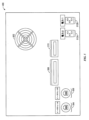
図4は、ある実施形態による、スタックライト402を含むセキュリティ機器拡張(SAE)パネル400の概略図である。SAEパネル400は、外部ソース(例えば、Syslogサーバ)から受け取られたシステムアラームをオペレータに通知し、任意に外部システムと連動して保護コンポーネント104を外部制御することができる。実行すべきアラーム動作が識別されると、DRSS100は、必要なLED404及びスタックライト402モジュールを作動させる。さらに、SAE108/DRSS100アプリケーションを表示して、セキュリティイベント及びその関連する特性評価を示すアラームバナーを含むグラフィカルユーザインターフェイス(GUI)を提供するディスプレイ406上に、アラーム指示を提示することができる。ディスプレイ406は、オペレータがセキュリティイベントをクリアし、以下でさらに詳細に説明するような他の制御動作を実行することを可能にするタッチ画面とすることができる。
4 is a schematic diagram of a security equipment extension (SAE)
SAEパネル400は、キースイッチ403を含むことができる。迂回キースイッチ403Aは、スイッチが2つの位置のどちらに対応しているかに応じてSAE108を実行モード又は迂回モードのいずれかの状態に入れる2位置キースイッチである実行/迂回キースイッチである。迂回モードでは、制御インターフェイス出力が現在のアラームを無視してONに維持される。DRSS100アプリケーションは、アラームを表示してログ記録し続ける。実行モードでは、本明細書で説明したような受け取られたセキュリティイベントに基づいて制御インターフェイス出力が作動する。
The
さらに、リセットスイッチ403Bを設けることもできる。上述したように、リセットスイッチ403Bは、回転させて一定期間(例えば、少なくとも10秒)保持することによって組み込み型コンピュータ106の電源を落とすことができるキースイッチとすることができる。「リセット」キーの保持を解放すると、組み込み型コンピュータ106が再起動する。
Additionally, a
LED404についてさらに詳細に説明すると、LED404Aは、第1の状態(例えば、点滅)の時には危機的セキュリティイベント特性評価を示し、第2の状態(例えば、点灯)の時には中セキュリティイベント特性評価を示す障害LEDである。LED404Bは、低アラーム特性評価を示す警告LEDである。LED404Cは、全てのインターフェイスが接続されており、実行/迂回キーが「迂回位置」ではなく「実行」位置にあることを示す正常LEDである。LED404Dは、PLC116が接続されてIOロジックを実行していることを示すIO接続LEDである。
To further describe LEDs 404,
次に、SAE108の外部インターフェイスを参照すると、図5は、ある実施形態によるSAEパネル400の背面の概略図である。図示のように、SAEパネル400は、SAEパネル400に空気流を提供する冷却ファン502を含む。
Referring now to the external interface of the
SAEパネル400は、組み込み型コンピュータ106をSyslogサーバ(例えば、図1のセキュリティ機器102)に通信可能に結合するために使用される、ここではRJ45イーサネットポートである第1の通信ポート504を含む。上述したように、Syslogサーバは、最終的には本明細書で説明したような提示及び/又は制御動作をトリガする特性評価されたセキュリティイベントになるSyslogメッセージを提供する。
The
SAEパネル400は、組み込み型コンピュータ106を図1のドメインコントローラ112に通信可能に結合するために使用される、ここではRJ45イーサネットポートである第2の通信ポート506も含む。上述したように、ドメインコントローラ112は、ユーザ認証を容易にして、以下でさらに詳細に説明するような保護制御機能を可能にすることができる。
The
SAEパネル400は、スタックライト/試験灯押しボタンインターフェイス508も含む。スタックライト/試験灯押しボタンインターフェイス508は、図4のアラームインジケータスタックライト402と、スタックライト402の診断点灯試験を実行するために押すことができる試験灯押しボタンとを接続する端子である。診断試験では、スタックライト402上の全てのライト及び音が瞬間的に作動する。
The
SAEパネル400は、制御インターフェイス510も含む。制御インターフェイス510は、提示及び/又は制御動作のための可能な限りのトリガを含むようにSAEパネル400を外部インターフェイスに接続する。PLC116は、制御インターフェイス510を介して指定出力を提供して、出力と制御インターフェイス端子ブロック上の共通端子との間の連続性を確立することができる。指定条件が満たされた場合、PLC116は、出力状態を変化させて連続性を遮断する。制御インターフェイス510によってサポートされるリモートインターフェイス出力は、ONに維持されるがいずれかのアラームが存在する場合にOFFに切り替わる「アラームなし」、及びONに維持されるが危機的アラームが存在する時にのみOFFに切り替わる出力のペアである「危機的アラームなし」を含む。上述したように、これらの状態変化は、実行/迂回キースイッチ403Aが「実行」に切り替わった時に作動する。しかしながら、実行/迂回キースイッチ403Aが「迂回」に切り替わった時には、いずれかのアラームの存在にもかかわらず、アラームなし及び危機的アラームなしの出力がONに維持されるようになる。
The
いくつかの実施形態では、制御インターフェイス510が、保護コンポーネントの動作変化を引き起こすことができる。例えば、制御インターフェイス510は、娯楽アトラクションに接続し、特性評価されたセキュリティイベント/生成されたアラームに基づいて娯楽アトラクション動作を制御することができる。例えば、危機的深刻度のセキュリティイベントが提示された時には、娯楽アトラクション(例えば、乗り物)を停止させ、及び/又は他の緩和措置を取ることができる。
In some embodiments, the
いくつかの実施形態では、SAEパネル500が、冗長電源512A及び512Bを含むことができる。二重電源を有することにより、電源512A又は512Bの一方への電力が欠乏した場合でも、代替電源512A又は512Bによって電源を維持することができる。以下でさらに詳細に説明するように、このようなイベント中には、電源512A又は512Bのどちらが機能していないかを示すローカルアラームを提示することができる。
In some embodiments, the SAE panel 500 can include
次に、DRSS100/SAE108アプリケーションGUIについてさらに詳細に説明すると、図6は、ある実施形態による、DRSSによって収集されたセキュリティイベントデータを示すグラフィカルユーザインターフェイス(GUI)起動画面600の概略図である。上述したように、DRSS100アプリケーションは、着信セキュリティイベント(例えば、Syslogメッセージ)をリスンし、スタックライト、LED及びアラームバナーを介してこのようなメッセージをオペレータに通報することに関与する。このアプリケーションは、受信時間、アラームがクリアされた時間及びアラームをクリアしたユーザを含むようにアラーム履歴をログ記録することができる。上述したように、このアプリケーションは、ドメイン認証を使用してセキュリティ保護することができ、オペレーティングシステムレベルでユーザの切り替えを必要とするのではなくアプリケーションレベルで認証を行うネイティブなバリデーションUIを含むことができる。
Now, going into further detail about the DRSS 100/
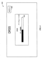
起動画面600に示すように、DRSS100アプリケーションは、最初に起動すると、全てのシステムインターフェイスに接続する起動プロセスを実行する。インターフェイスが通信できない場合には、起動画面600上に通信障害を示すメッセージが表示され、アプリケーションが一定期間(例えば、10秒)後に自動的に再接続しようと試みる。初期データセット(例えば、システムインターフェイスとの通信及び/又はイベントメッセージを示すデータ)が検索されると、進捗バー602が、ローディングプロセスが100%完了して起動画面600がメイン表示画面に移行する旨を示す。ローディングプロセス中、オペレータは、ログインアフォーダンス(login affordance)604を使用してログインすることができる。オペレータは、ログインすることによって、認証ユーザのみが利用できる保護動作を実行することができる。ログインプロセスについては、以下でさらに詳細に説明する。
As shown in the
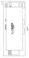
図7は、ある実施形態による、DRSS100アプリケーションGUIのメイン表示画面700の概略図である。メイン表示画面700は、DRSS100によって受け取られたアクティブなアラームを表示するアラームバナー702を提供する。アラームバナーには優先順位が付けられ、最も優先度の高いアラームが最初に提示される。さらに、バナー702を差別化することによってセキュリティイベントの特性評価が提供される。例えば、バナー702Aは赤色バナーであり、バナー702Aに関連するセキュリティアラートが深刻度3のセキュリティイベントとして特性評価されていることを示すテキスト指示を提供する。対照的に、バナー702B~Dは、それぞれ深刻度2のセキュリティイベントとして特性評価されたセキュリティイベントに関連する。
Figure 7 is a schematic diagram of a
メイン表示画面700上には、作動時にあらゆる現在の可聴アラームを設定可能時間(例えば、30秒のデフォルト時間)にわたって無音化する無音化ボタン704が設けられる。いくつかの実施形態では、無音化ボタン704がユーザ確認の作動を必要としない。しかしながら、グレーアウト表示された全クリアボタン706及びクリアボタン708によって示すように、いくつかの実施形態では、これらのオプションを(例えば、ログインボタン604を選択することによってログインプロセスを実行することによって)ログイン時にのみ選択することができる。
Also provided on the
図8は、ある実施形態によるGUIログイン画面800の概略図である。ログイン画面800は、オペレータによるログインクレデンシャル(例えば、ユーザID802及びパスワード804)の入力を可能にする。別の実施形態では、生体認証、物理キーなどの他のログインクレデンシャルを使用してDRSS100アプリケーションにログインすることができる。
FIG. 8 is a schematic diagram of a
オペレータがログインすると、全クリアボタン706及びクリアボタン708が有効になる。図9は、ある実施形態による、ログイン後に特殊機能(例えば、全クリアボタン706及びクリアボタン708)を有効にするGUIメイン画面900の概略図である。全クリアボタン706は、選択されると、いずれかのアラームバナー702の行の一切の選択にかかわらず、アラームバナー702によって表される全てのアラームをクリアする。クリアボタン708は、選択されると、選択されたアラームバナー702に関連するセキュリティイベントをクリアする。オペレータは、アラームバナー702を選択するために単純にアラームバナー702をタップすることができる。選択されたアラームバナー702は、そのアラームバナー702が選択されたことを示すために特性(例えば、色)を変化させる。さらに、アラームバナー702は、アラームバナー702を二度目にタップすることによって未選択にすることができる。
Once the operator logs in, the clear all
図示のように、オペレータがログインした後にはログアウトボタン902も提供される。ログアウトボタン902は、選択されるとオペレータがログアウトされる(そして、グレーアウト表示されたオプションを含むメイン画面700が再び表示される)。
As shown, after an operator has logged in, a
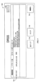
DRSS100は、セキュリティ機器102から生成されたアラームを提供することに加えて、局所的イベントに基づいてアラームを生成することもできる。例えば、図10は、ある実施形態による、エラーを提示するDRSS100のGUI1000の概略図である。図示の実施形態では、DRSS100によってセキュリティイベント(例えば、Syslogメッセージ)が受け取られていないことを示すセンサ通信障害メッセージ1002が提示されている。DRSS100アプリケーションは、セキュリティイベントが提示されない時に偽エラーが提示されないことを確実にするために、セキュリティセンサ(例えば、Syslogサーバ/セキュリティ機器102)から一定間隔でハートビートメッセージ(heartbeat messages)を受け取ることができる。本明細書で使用するハートビートメッセージは、いつDRSS100によってメッセージが受け取られていないかを判定するために使用できる定期的予想メッセージである。ハートビートメッセージが検出されない場合、アプリケーションは、ハートビート障害を示すGUI1000を提示する。ハートビートメッセージが検出されると、GUI1000が消えて、アプリケーションは通常動作を再開する。いくつかの実施形態では、ハートビートメッセージの間隔、及びアラーム生成前の許容可能な紛失ハートビートメッセージ数が設定可能である。
In addition to providing alarms generated from the
DRSS100は、さらなるローカルアラームを含むことができる。以下は、さらなるアラーム、並びに深刻度特性評価及び説明のリストである。

本明細書で述べたように、DRSS100は、複数の用途に適した個別のアラーム提示及び制御体験をもたらす多くの方法で構成することができる。いくつかの実施形態では、DRSS100アプリケーションが、アプリケーションを再インストールする必要なく構成可能パラメータをロードするXML構成可能ファイルを含むことができる。以下は、構成パラメータ、デフォルト値及び各構成パラメータの説明のリストである。理解できるように、このリストは可能な構成パラメータの1つのリストであるが、このような構成パラメータに範囲を限定するように意図するものではない。実際には、別の実施形態におけるオプションとして、より少ない又はより多くの構成パラメータを提示することができる。


本明細書に示して特許請求する技術は、本技術分野を確実に改善する、従って抽象的なもの、無形のもの又は純粋に理論的なものではない実際的性質の有形物及び具体例を参照し、これらに適用される。さらに、本明細書の最後に添付するいずれかの請求項が、「...[機能]を[実行]する手段」又は「...[機能]を[実行]するステップ」として指定されている1又は2以上の要素を含む場合、このような要素は米国特許法112条(f)に従って解釈すべきである。一方で、他のいずれかの形で指定された要素を含むあらゆる請求項については、このような要素を米国特許法112条(f)に従って解釈すべきではない。 The technology presented and claimed herein refers to and applies to tangible objects and specific examples of a practical nature that positively improve the art and are therefore not abstract, intangible, or purely theoretical. Moreover, if any claim appended at the end of this specification contains one or more elements designated as "means for [performing] . . . [function]" or "steps for [performing] . . . [function]," such elements are to be construed pursuant to 35 U.S.C. 112(f); whereas, for any claim containing elements designated in any other manner, such elements are not to be construed pursuant to 35 U.S.C. 112(f).
100 検出及び対応セキュリティシステム(DRSS)
102 セキュリティ機器
104 保護コンポーネント
106 組み込み型コンピュータ
108 セキュリティ機器拡張(SAE)
110 Syslogマッピング
112 ドメインコントローラ
114 ドメインコントローラ
116 PLC
100 Detection and Response Security System (DRSS)
102
110 Syslog mapping 112
Claims (20)
1又は2以上のプロセッサを含む組み込み型コンピュータを備え、前記1又は2以上のプロセッサは、
セキュリティ機器から、保護コンポーネントに関連するセキュリティイベントをそれぞれが示す1又は2以上のセキュリティイベントメッセージを受け取り、
前記1又は2以上のセキュリティイベントメッセージにおける第1のコードから、前記1又は2以上のセキュリティイベントメッセージをログ記録するプログラムの第1のタイプの指示を識別し、前記第1のコードは複数のコードの予め決められたリストのうちの1つであり、前記複数のコードの各々は前記1又は2以上のセキュリティイベントメッセージをログ記録するプログラムのそれぞれのタイプを指定するために使用され、
前記1又は2以上のセキュリティイベントメッセージをログ記録するプログラムの第1のタイプの前記識別に少なくとも部分的に基づいて前記1又は2以上のセキュリティイベントメッセージの第1の独自の深刻度特性評価を識別し、前記第1の独自の深刻度特性評価は、前記複数のコードの前記予め決められたリストの第2のコードによって指定される前記1又は2以上のセキュリティイベントメッセージをログ記録するプログラムの第2のタイプの指示に少なくとも部分的に基づいて識別される第2の独自の深刻度特性評価とは異なり、
前記第1の独自の深刻度特性評価に基づいて実行すべき1又は2以上の提示又は制御動作を決定し、
前記1又は2以上の提示又は制御動作を実行する、
ように構成される、
ことを特徴とする電子装置。 1. An electronic device comprising:
An embedded computer including one or more processors, the one or more processors comprising:
receiving one or more security event messages from the security device, each indicating a security event associated with a protection component;
identifying an indication of a first type of program logging the one or more security event messages from a first code in the one or more security event messages, the first code being one of a predetermined list of a plurality of codes, each of the plurality of codes used to designate a respective type of program logging the one or more security event messages;
identifying a first unique severity characterization of the one or more security event messages based at least in part on the identification of a first type of program that logs the one or more security event messages , the first unique severity characterization being distinct from a second unique severity characterization identified based at least in part on an indication of a second type of program that logs the one or more security event messages specified by a second code of the predetermined list of codes;
determining one or more presentation or control actions to perform based on the first unique severity characterization;
Executing the one or more presentation or control operations;
It is configured as follows:
1. An electronic device comprising:
請求項1に記載の電子装置。 the first unique severity characterization is determined by executing a mapping script that maps one or more characteristics of the one or more security event messages received by the security device to a particular unique severity characterization expected by the embedded computer.
2. The electronic device of claim 1.
請求項2に記載の電子装置。 the one or more characteristics of the one or more security event messages received by the security device include a first severity level, and the particular unique severity characteristic anticipated by the embedded computer is a second severity level.
3. The electronic device of claim 2.
請求項2に記載の電子装置。 the one or more processors of the embedded computer are configured to execute the mapping script.
3. The electronic device of claim 2.
請求項2に記載の電子装置。 the first independent severity characterization is received from the security device;
3. The electronic device of claim 2.
前記ディスプレイ上のグラフィカルユーザインターフェイス(GUI)を介して、前記第1の独自の深刻度特性評価に基づいて、前記1又は2以上のセキュリティイベントメッセージに関連する1又は2以上のアラームバナーを提示すること、又は、
スタックライトを介して、前記第1の独自の深刻度特性評価に基づいて、前記1又は2以上のセキュリティイベントメッセージに関連する1又は2以上の視覚的アラーム指示を提示すること、又は、
これらの両方、
を含む、請求項1に記載の電子装置。 a display, and the one or more presentation or control operations include:
presenting, via a graphical user interface (GUI) on the display, one or more alarm banners associated with the one or more security event messages based on the first unique severity characterization; or
presenting, via a stack light, one or more visual alarm indications associated with the one or more security event messages based on the first unique severity characterization; or
Both of these,
The electronic device of claim 1 .
請求項1に記載の電子装置。 and wherein the one or more indicating or controlling actions include modifying an operational state of the protection component.
2. The electronic device of claim 1.
請求項7に記載の電子装置。 the protective component includes an entertainment attraction;
8. The electronic device of claim 7.
請求項1に記載の電子装置。 the one or more security event messages include messages generated in accordance with the Syslog standard for message logging;
2. The electronic device of claim 1.
前記1又は2以上のI/Oコマンドを示すI/Oデータを受け取って前記1又は2以上のI/Oコマンドを実行し、又は、
前記1又は2以上の出力指示を受け取り、前記1又は2以上のI/O装置を介して前記1又は2以上の出力指示を提示し、又は、
これらの両方を行う、
ように構成されたプログラマブルロジックコントローラ(PLC)と、
を備える、請求項1に記載の電子装置。 one or more input/output (I/O) devices configured to receive one or more I/O commands from an operator of the electronic device, or to provide one or more output instructions to the operator, or both;
receiving I/O data indicative of the one or more I/O commands and executing the one or more I/O commands; or
receiving the one or more output instructions and presenting the one or more output instructions via the one or more I/O devices; or
Do both of these things,
A programmable logic controller (PLC) configured as described above;
The electronic device of claim 1 .
前記1又は2以上のライトの組は、第1の状態の時に危機的深刻度セキュリティイベントを、第2の状態の時に中深刻度セキュリティイベントを選択的に示す障害発光ダイオード(LED)を含み、
前記1又は2以上のライトの組は、全ての予想されるインターフェイスが前記電子装置に通信可能に結合されているかどうかを示す正常発光ダイオード(LED)を含む、
請求項10に記載の電子装置。 the one or more I/O devices include a set of one or more lights that provide an indication of the first unique severity characterization;
the set of one or more lights includes a fault light emitting diode (LED) selectively indicating a critical severity security event under a first condition and a medium severity security event under a second condition;
the set of one or more lights includes a normal light emitting diode (LED) that indicates whether all expected interfaces are communicatively coupled to the electronic device;
11. The electronic device of claim 10.
前記PLCの変数の継続的に変化する状態が前記組み込み型コンピュータにおいて閾値時間内に検出されない時を判定し、
前記継続的に変化する変数の状態を前記閾値時間内に検出しなかったことに応答して、前記組み込み型コンピュータの機能不全を示す障害を提供する、
ように構成される、請求項10に記載の電子装置。 The embedded computer includes:
determining when a continuously changing state of a variable of the PLC is not detected in the embedded computer within a threshold time;
and in response to failing to detect the state of the continuously changing variable within the threshold time, providing a fault indicative of a malfunction of the embedded computer.
The electronic device according to claim 10 , configured to:
実行モードの場合、前記1又は2以上のセキュリティイベントメッセージが受け取られた時に、前記1又は2以上のセキュリティイベントメッセージに関連する1又は2以上のアラームバナーをログ記録させて提示させ、前記1又は2以上のセキュリティイベントメッセージに関連する1又は2以上のアラームを提示させ、
迂回モードの場合、前記1又は2以上のセキュリティイベントメッセージが受け取られた時に、前記1又は2以上のセキュリティイベントメッセージに関連する前記1又は2以上のアラームバナーをログ記録させて提示させ、前記1又は2以上のセキュリティイベントメッセージに関連する前記1又は2以上のアラームの提示を控えさせる、
請求項10に記載の電子装置。 The one or more I/O devices include a execute/bypass switch, the execute/bypass switch comprising:
in an execution mode, when the one or more security event messages are received, logging and presenting one or more alarm banners associated with the one or more security event messages and presenting one or more alarms associated with the one or more security event messages;
in a bypass mode, when the one or more security event messages are received, cause the one or more alarm banners associated with the one or more security event messages to be logged and presented, and cause the one or more alarms associated with the one or more security event messages to be refrained from being presented;
11. The electronic device of claim 10.
請求項10に記載の電子装置。 the one or more I/O devices include a reset switch that, when placed in a reset mode, causes the embedded computer to power down, reboot, or both;
11. The electronic device of claim 10.
セキュリティ機器から、保護コンポーネントに関連するセキュリティイベントをそれぞれが示す1又は2以上のセキュリティイベントメッセージを受け取ることと、
前記1又は2以上のセキュリティイベントメッセージにおける第1のコードから、前記1又は2以上のセキュリティイベントメッセージをログ記録するプログラムの第1のタイプの指示を識別することであって、前記第1のコードは複数のコードの予め決められたリストのうちの1つであり、前記複数のコードの各々は前記1又は2以上のセキュリティイベントメッセージをログ記録するプログラムのそれぞれのタイプを指定するために使用される、ことと、
前記1又は2以上のセキュリティイベントメッセージをログ記録するプログラムの第1のタイプの前記識別に少なくとも部分的に基づいて前記1又は2以上のセキュリティイベントメッセージの第1の独自の深刻度特性評価を識別することと、
前記第1の独自の深刻度特性評価に基づいて実行すべき1又は2以上の提示又は制御動作を決定することであって、前記第1の独自の深刻度特性評価は、前記複数のコードの前記予め決められたリストの第2のコードによって指定される前記1又は2以上のセキュリティイベントメッセージをログ記録するプログラムの第2のタイプの指示に少なくとも部分的に基づいて識別される第2の独自の深刻度特性評価とは異なる、ことと、
前記1又は2以上の提示又は制御動作を実行することと、
を前記コンピュータシステムに行わせるコンピュータ可読命令を含む、ことを特徴とするコンピュータ可読媒体。 A tangible, non-transitory computer-readable medium that, when executed by one or more processors of a computer system ,
receiving one or more security event messages from a security device, each indicating a security event associated with a protection component;
identifying an indication of a first type of program that logs the one or more security event messages from a first code in the one or more security event messages, the first code being one of a predetermined list of a plurality of codes, each of the plurality of codes being used to designate a respective type of program that logs the one or more security event messages;
identifying a first unique severity characterization of the one or more security event messages based at least in part on the identification of a first type of program logging the one or more security event messages ;
determining one or more presentation or control actions to perform based on the first unique severity characterization, the first unique severity characterization being different from a second unique severity characterization identified based at least in part on a second type of instruction of a program to log the one or more security event messages specified by a second code of the predetermined list of codes;
performing the one or more presentation or control actions;
23. A computer-readable medium comprising computer-readable instructions for causing the computer system to:
請求項15に記載のコンピュータ可読媒体。 and computer readable instructions that, when executed by the one or more processors, cause the computer system to identify the first unique severity characterization by executing a mapping script that maps one or more characteristics of the one or more security event messages received by the security device to a particular unique severity characterization expected by the computer system .
16. The computer readable medium of claim 15.
請求項15に記載のコンピュータ可読媒体。 computer readable instructions that, when executed by the one or more processors, cause the computer system to present within a graphical user interface (GUI) of the computer system one or more alarm banners corresponding to the one or more security event messages and an indication of the first unique severity characterization of the one or more security event messages.
16. The computer readable medium of claim 15.
プログラマブルロジックコントローラ(PLC)の変数の継続的に変化する状態が前記コンピュータシステムにおいて閾値時間内に検出されない時を判定することと、
前記継続的に変化する変数の状態を前記閾値時間内に検出しなかったことに応答して、前記コンピュータシステムの機能不全を示す障害を提供することと、
を前記コンピュータシステムに行わせるコンピュータ可読命令を含む、請求項15に記載のコンピュータ可読媒体。 When executed by the one or more processors,
determining when a continuously changing state of a programmable logic controller (PLC) variable is not detected in the computer system within a threshold time;
providing a fault indicative of a malfunction of the computer system in response to not detecting the state of the continuously changing variable within the threshold time;
20. The computer readable medium of claim 15, comprising computer readable instructions for causing the computer system to:
前記1又は2以上のセキュリティイベントメッセージにおける第1のコードから、前記1又は2以上のセキュリティイベントメッセージをログ記録するプログラムの第1のタイプの指示を識別することであって、前記第1のコードは複数のコードの予め決められたリストのうちの1つであり、前記複数のコードの各々は前記1又は2以上のセキュリティイベントメッセージをログ記録するプログラムのそれぞれのタイプを指定するために使用される、ことと、
前記1又は2以上のセキュリティイベントメッセージをログ記録するプログラムの第1のタイプの前記識別に少なくとも部分的に基づいて前記1又は2以上のセキュリティイベントメッセージの第1の独自の深刻度特性評価を、前記コンピュータシステムを介して識別することであって、前記第1の独自の深刻度特性評価は、前記複数のコードの前記予め決められたリストの第2のコードによって指定される前記1又は2以上のセキュリティイベントメッセージをログ記録するプログラムの第2のタイプの指示に少なくとも部分的に基づいて識別される第2の独自の深刻度特性評価とは異なる、ことと、
前記第1の独自の深刻度特性評価に基づいて実行すべき1又は2以上の提示又は制御動作を決定することと、
前記1又は2以上の提示又は制御動作を実行することと、
を含むことを特徴とするコンピュータに実装された方法。 receiving one or more security event messages from the security device via the computer system , each security event message indicating a security event associated with a protection component;
identifying an indication of a first type of program that logs the one or more security event messages from a first code in the one or more security event messages, the first code being one of a predetermined list of a plurality of codes, each of the plurality of codes being used to designate a respective type of program that logs the one or more security event messages;
identifying, via the computer system, a first unique severity characterization of the one or more security event messages based at least in part on the identification of a first type of program that logs the one or more security event messages , the first unique severity characterization being different from a second unique severity characterization identified based at least in part on an indication of a second type of program that logs the one or more security event messages specified by a second code of the predetermined list of codes;
determining one or more presentation or control actions to perform based on the first unique severity characterization;
performing the one or more presentation or control actions;
23. A computer-implemented method comprising:
スタックライトを介して、前記第1の独自の深刻度特性評価に基づいて、前記1又は2以上のセキュリティイベントメッセージに関連する1又は2以上の視覚的アラーム指示を提示すること、又は、
これらの両方、
を含む、請求項19に記載のコンピュータに実装された方法。 presenting, via a graphical user interface (GUI), one or more alarm banners associated with the one or more security event messages based on the first unique severity characterization; or
presenting, via a stack light, one or more visual alarm indications associated with the one or more security event messages based on the first unique severity characterization; or
Both of these,
20. The computer-implemented method of claim 19, comprising:
Applications Claiming Priority (5)
| Application Number | Priority Date | Filing Date | Title |
|---|---|---|---|
| US201962817304P | 2019-03-12 | 2019-03-12 | |
| US62/817,304 | 2019-03-12 | ||
| US16/439,421 | 2019-06-12 | ||
| US16/439,421 US12579257B2 (en) | 2019-03-12 | 2019-06-12 | Security appliance extension |
| PCT/US2020/021901 WO2020185785A1 (en) | 2019-03-12 | 2020-03-10 | Security appliance extension |
Publications (2)
| Publication Number | Publication Date |
|---|---|
| JP2022523965A JP2022523965A (en) | 2022-04-27 |
| JP7538136B2 true JP7538136B2 (en) | 2024-08-21 |
Family
ID=72423243
Family Applications (1)
| Application Number | Title | Priority Date | Filing Date |
|---|---|---|---|
| JP2021552559A Active JP7538136B2 (en) | 2019-03-12 | 2020-03-10 | Security Device Expansion |
Country Status (9)
| Country | Link |
|---|---|
| US (2) | US12579257B2 (en) |
| EP (1) | EP3938938A1 (en) |
| JP (1) | JP7538136B2 (en) |
| KR (1) | KR20210137512A (en) |
| CN (2) | CN119903508A (en) |
| CA (1) | CA3133935A1 (en) |
| MY (1) | MY210155A (en) |
| SG (1) | SG11202108934UA (en) |
| WO (1) | WO2020185785A1 (en) |
Citations (7)
| Publication number | Priority date | Publication date | Assignee | Title |
|---|---|---|---|---|
| US20060129877A1 (en) | 2002-10-07 | 2006-06-15 | Masayuki Yamamoto | Volume and failure management method on a network having a storage device |
| US20070234426A1 (en) | 2000-06-23 | 2007-10-04 | Rajeev Khanolkar | Comprehensive security structure platform for network managers |
| JP2011008495A (en) | 2009-06-25 | 2011-01-13 | Koyo Electronics Ind Co Ltd | Voice guide system for system malfunction |
| JP2013156789A (en) | 2012-01-30 | 2013-08-15 | Hitachi Ltd | Failure monitoring method and failure monitoring program |
| JP2014228932A (en) | 2013-05-20 | 2014-12-08 | 日本電気通信システム株式会社 | Failure notification device, failure notification program, and failure notification method |
| JP2017536861A (en) | 2014-10-02 | 2017-12-14 | マック ライズ ゲーエムベーハー ウント コー カーゲーMack Rides GmbH & Co.KG | In particular, mechatronic safety systems for amusement vehicles such as jet coasters and carousels |
| JP2018049602A (en) | 2016-09-06 | 2018-03-29 | アクセンチュア グローバル ソリューションズ リミテッド | Graph database analysis for network anomaly detection systems |
Family Cites Families (28)
| Publication number | Priority date | Publication date | Assignee | Title |
|---|---|---|---|---|
| JP3467330B2 (en) * | 1994-09-22 | 2003-11-17 | 富士通株式会社 | System abnormality monitoring device |
| US6915457B1 (en) * | 1999-04-23 | 2005-07-05 | Nortel Networks Limited | Apparatus and method for monitoring messages forwarded between applications |
| US20030051026A1 (en) * | 2001-01-19 | 2003-03-13 | Carter Ernst B. | Network surveillance and security system |
| US20040006652A1 (en) * | 2002-06-28 | 2004-01-08 | Prall John M. | System event filtering and notification for OPC clients |
| US7219239B1 (en) * | 2002-12-02 | 2007-05-15 | Arcsight, Inc. | Method for batching events for transmission by software agent |
| US7308689B2 (en) | 2002-12-18 | 2007-12-11 | International Business Machines Corporation | Method, apparatus, and program for associating related heterogeneous events in an event handler |
| US20070288925A1 (en) * | 2006-04-04 | 2007-12-13 | Computer Associates Think, Inc. | Arrangements, Methods, and Software for Managing Objects and Resolving Different Types of Events Associated with Such Objects |
| US7934253B2 (en) * | 2006-07-20 | 2011-04-26 | Trustwave Holdings, Inc. | System and method of securing web applications across an enterprise |
| TWI434190B (en) * | 2006-12-28 | 2014-04-11 | Hewlett Packard Development Co | Storing log data efficiently while supporting querying to assist in computer network security |
| US9378066B2 (en) * | 2008-02-25 | 2016-06-28 | Sap Se | Dynamic resizing of applications running on virtual machines |
| US20100128432A1 (en) * | 2008-06-16 | 2010-05-27 | Miller Matthew P | System and method for virtual computing environment management, network interface manipulation and information indication |
| WO2010028279A1 (en) * | 2008-09-05 | 2010-03-11 | Arcsight, Inc. | Storing log data efficiently while supporting querying |
| US20120296845A1 (en) * | 2009-12-01 | 2012-11-22 | Andrews Sarah L | Methods and systems for generating composite index using social media sourced data and sentiment analysis |
| US20120254607A1 (en) * | 2011-04-01 | 2012-10-04 | International Business Machines Corporation | System And Method For Security Levels With Cluster Communications |
| EP2566102B1 (en) * | 2011-08-31 | 2014-03-26 | ABB Technology AG | Security event logging and conversion of security event messages in process control |
| US10771532B2 (en) | 2011-10-04 | 2020-09-08 | Electro Industries/Gauge Tech | Intelligent electronic devices, systems and methods for communicating messages over a network |
| US8839349B2 (en) * | 2011-10-18 | 2014-09-16 | Mcafee, Inc. | Integrating security policy and event management |
| US8898273B2 (en) * | 2012-10-10 | 2014-11-25 | JFH Technologies Inc. | Electronic adverse event reporting system |
| JP2016534479A (en) * | 2013-09-12 | 2016-11-04 | ヴァーセック・システムズ・インコーポレーテッドVirsec Systems,Inc. | Automatic detection during malware runtime |
| US9396089B2 (en) * | 2014-05-30 | 2016-07-19 | Apple Inc. | Activity tracing diagnostic systems and methods |
| US10250619B1 (en) * | 2015-06-17 | 2019-04-02 | Mission Secure, Inc. | Overlay cyber security networked system and method |
| US9697355B1 (en) | 2015-06-17 | 2017-07-04 | Mission Secure, Inc. | Cyber security for physical systems |
| US10122748B1 (en) * | 2015-08-21 | 2018-11-06 | InsCyt, LLC | Network protection system and threat correlation engine |
| CN108513655B (en) * | 2015-10-13 | 2022-06-03 | 施耐德电器工业公司 | Software defined automation system and architecture thereof |
| KR102098064B1 (en) | 2015-11-16 | 2020-04-07 | 주식회사 마크애니 | Method, Apparatus and System for Security Monitoring Based On Log Analysis |
| CN105530136B (en) | 2016-01-30 | 2018-10-12 | 山东大学 | A kind of electric power dispatching system business monitoring method and system |
| JP7028559B2 (en) | 2017-01-25 | 2022-03-02 | エヌ・ティ・ティ・コミュニケーションズ株式会社 | Attack detection system, attack detection method and attack detection program |
| DK3528462T3 (en) * | 2018-02-20 | 2024-02-26 | Darktrace Holdings Ltd | Approach to share a cybersecurity threat analysis and defensive measures in a community |
-
2019
- 2019-06-12 US US16/439,421 patent/US12579257B2/en active Active
-
2020
- 2020-03-10 MY MYPI2021004649A patent/MY210155A/en unknown
- 2020-03-10 JP JP2021552559A patent/JP7538136B2/en active Active
- 2020-03-10 CN CN202411901290.7A patent/CN119903508A/en active Pending
- 2020-03-10 KR KR1020217032217A patent/KR20210137512A/en not_active Ceased
- 2020-03-10 CA CA3133935A patent/CA3133935A1/en active Pending
- 2020-03-10 CN CN202080020484.XA patent/CN113557510B/en active Active
- 2020-03-10 SG SG11202108934UA patent/SG11202108934UA/en unknown
- 2020-03-10 EP EP20714098.9A patent/EP3938938A1/en active Pending
- 2020-03-10 WO PCT/US2020/021901 patent/WO2020185785A1/en not_active Ceased
-
2023
- 2023-12-07 US US18/532,386 patent/US20240256662A1/en active Pending
Patent Citations (7)
| Publication number | Priority date | Publication date | Assignee | Title |
|---|---|---|---|---|
| US20070234426A1 (en) | 2000-06-23 | 2007-10-04 | Rajeev Khanolkar | Comprehensive security structure platform for network managers |
| US20060129877A1 (en) | 2002-10-07 | 2006-06-15 | Masayuki Yamamoto | Volume and failure management method on a network having a storage device |
| JP2011008495A (en) | 2009-06-25 | 2011-01-13 | Koyo Electronics Ind Co Ltd | Voice guide system for system malfunction |
| JP2013156789A (en) | 2012-01-30 | 2013-08-15 | Hitachi Ltd | Failure monitoring method and failure monitoring program |
| JP2014228932A (en) | 2013-05-20 | 2014-12-08 | 日本電気通信システム株式会社 | Failure notification device, failure notification program, and failure notification method |
| JP2017536861A (en) | 2014-10-02 | 2017-12-14 | マック ライズ ゲーエムベーハー ウント コー カーゲーMack Rides GmbH & Co.KG | In particular, mechatronic safety systems for amusement vehicles such as jet coasters and carousels |
| JP2018049602A (en) | 2016-09-06 | 2018-03-29 | アクセンチュア グローバル ソリューションズ リミテッド | Graph database analysis for network anomaly detection systems |
Also Published As
| Publication number | Publication date |
|---|---|
| US20240256662A1 (en) | 2024-08-01 |
| SG11202108934UA (en) | 2021-09-29 |
| US20200293654A1 (en) | 2020-09-17 |
| CN119903508A (en) | 2025-04-29 |
| CN113557510A (en) | 2021-10-26 |
| CA3133935A1 (en) | 2020-09-17 |
| MY210155A (en) | 2025-08-29 |
| WO2020185785A1 (en) | 2020-09-17 |
| US12579257B2 (en) | 2026-03-17 |
| CN113557510B (en) | 2024-12-31 |
| JP2022523965A (en) | 2022-04-27 |
| KR20210137512A (en) | 2021-11-17 |
| EP3938938A1 (en) | 2022-01-19 |
Similar Documents
| Publication | Publication Date | Title |
|---|---|---|
| US7617086B2 (en) | Monitoring simulating device, method, and program | |
| US20160352770A1 (en) | Software/Hardware Device with Uncertain Service Function and Structural Characterization, and Scheduling Method for Thereof | |
| US9818276B2 (en) | Fire alarm controller configuration apparatus and configuration method thereof | |
| US9164851B2 (en) | Keyboard, video and mouse switch identifying and displaying nodes experiencing a problem | |
| US20210091852A1 (en) | Enhanced led signaling status for network device onboarding | |
| CN106980562A (en) | A kind of hard disk monitoring method and device | |
| US9076316B2 (en) | System and method for verifying associations between intiating devices and notifications applicances in alarm systems | |
| JP4962725B2 (en) | Tool device in multi PLC / distributed control system | |
| US8421644B2 (en) | Light-emitting diode control system and method | |
| JP5054654B2 (en) | Plant operation device | |
| CN110232881A (en) | Front board measuring method | |
| US20240256662A1 (en) | Security appliance extension | |
| HK40126405A (en) | Security appliance extension | |
| HK40063589A (en) | Security appliance extension | |
| HK40063589B (en) | Security appliance extension | |
| CN115231421A (en) | A light curtain control method, device, elevator light curtain and storage medium | |
| JP2017114645A (en) | Elevator maintenance management system | |
| CN106485894B (en) | Safety system, method and apparatus for commissioning a safety system | |
| RU2021129521A (en) | SAFETY DEVICE ATTACHMENT | |
| JP7808228B2 (en) | Smoke Monitoring System | |
| US9218237B1 (en) | Network of interconnected circuit protection devices | |
| KR100809290B1 (en) | Process management device using PDR and its method | |
| CN109255233B (en) | Vulnerability detection method and device | |
| JPH05274317A (en) | Household automation system | |
| JP2019026451A (en) | Elevator monitoring system and testing method thereof |
Legal Events
| Date | Code | Title | Description |
|---|---|---|---|
| A621 | Written request for application examination |
Free format text: JAPANESE INTERMEDIATE CODE: A621 Effective date: 20230221 |
|
| A131 | Notification of reasons for refusal |
Free format text: JAPANESE INTERMEDIATE CODE: A131 Effective date: 20240220 |
|
| A977 | Report on retrieval |
Free format text: JAPANESE INTERMEDIATE CODE: A971007 Effective date: 20240221 |
|
| A521 | Request for written amendment filed |
Free format text: JAPANESE INTERMEDIATE CODE: A523 Effective date: 20240501 |
|
| TRDD | Decision of grant or rejection written | ||
| A01 | Written decision to grant a patent or to grant a registration (utility model) |
Free format text: JAPANESE INTERMEDIATE CODE: A01 Effective date: 20240709 |
|
| A61 | First payment of annual fees (during grant procedure) |
Free format text: JAPANESE INTERMEDIATE CODE: A61 Effective date: 20240808 |
|
| R150 | Certificate of patent or registration of utility model |
Ref document number: 7538136 Country of ref document: JP Free format text: JAPANESE INTERMEDIATE CODE: R150 |